Cargo Container X-ray Inspection Systems - Hitachi
Cargo Container X-ray Inspection Systems - Hitachi
Cargo Container X-ray Inspection Systems - Hitachi

You also want an ePaper? Increase the reach of your titles
YUMPU automatically turns print PDFs into web optimized ePapers that Google loves.
<strong>Cargo</strong> <strong>Container</strong> X-<strong>ray</strong> <strong>Inspection</strong> <strong>Systems</strong><br />
INTRODUCTION<br />
A single container ship carries an average of 3,000–<br />
8,000 containers. To open each container and remove<br />
and inspect its cargo would be both time-consuming<br />
and unrealistic. In order to conduct inspections<br />
effectively and efficiently, large-size X-<strong>ray</strong> DR (digital<br />
radiography) equipment is used to inspect containers<br />
loaded aboard their trailers (see Fig. 1). For X-<strong>ray</strong>s<br />
capable of scanning cargo inside a container —<br />
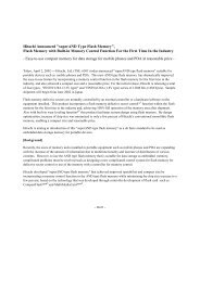
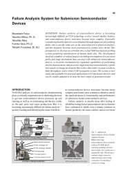
Fig. 1—Overall View of <strong>Container</strong> <strong>Inspection</strong> Center.<br />
A container inspection center is often located near a seaport<br />
container terminal. The center consists of two types of<br />
inspection facilities. One is for inspecting cargo containers<br />
using large-size X-<strong>ray</strong> equipment while loaded on trailers. The<br />
other unit is for individual inspection of all cargo inside a<br />
container when the trailer X-<strong>ray</strong> inspection identifies a<br />
suspicious piece of cargo.<br />
<strong>Hitachi</strong> Review Vol. 53 (2004), No. 2 97<br />
OVERVIEW: <strong>Container</strong> inspection is categorized into three stages. In the<br />
initial stage, large-size X-<strong>ray</strong> DR (digital radiography) is used to inspect<br />
full containers sitting on their trailers. If that inspection identifies suspicious<br />
cargo, the trailer and container are relocated to a nearby inspection position<br />
for opening the container and inspecting all cargo inside. In the second<br />
stage, small-size X-<strong>ray</strong> DR equipment is used to inspect each cargo. If a<br />
suspicious cargo is detected here, it is then opened, the contents are extracted<br />
and checked by manual procedure. For cargoes that cannot be opened, such<br />
as religious statues or works of art such as sculptures, third-stage inspections<br />
are conducted using an X-<strong>ray</strong> (computed tomographic) scanner. <strong>Hitachi</strong>,<br />
Ltd. is the only manufacturer in the world that can provide the equipment<br />
needed in all three cargo-container inspection stages.<br />
actually, a steel-walled box — a linear accelerator<br />
(linac) that generates 9 MeV (9 mega electron-volts)<br />
is used.<br />
If the first inspection stage identifies suspicious<br />
cargo in a container, the trailer is driven to a nearby<br />
station in the inspection center where the container is<br />
opened and each piece of cargo inside is inspected<br />
using X-<strong>ray</strong> DR equipment. Suspicious cargoes<br />
detected in that inspection are then opened, the<br />
contents are extracted and checked manually. The<br />
equipment used in this second-stage inspection<br />
includes an X-<strong>ray</strong> tube that generates several hundred<br />
keV (kilo electron-volts).<br />
For cargo that cannot be opened, such as religious<br />
statues or works of art, including sculptures, an X-<strong>ray</strong><br />
CT (computed tomographic) scanner is used to create<br />
tomographic images for viewing. Since cargo in this<br />
third-stage inspection process is often made of metal<br />
or marble, a linac with energy of about 1 MeV is used.<br />
X-<strong>ray</strong> scanning equipment is convenient to use<br />
because turning off the power source halts its<br />
operation. It is used in a wide range of applications.<br />
The following paper introduces various types of<br />
inspection equipment.<br />
OUTLINE OF X-RAY INSPECTION<br />
EQUIPMENT<br />
X-<strong>ray</strong> Equipment for Inspecting <strong>Container</strong>s<br />
(1) Outline of equipment<br />
The X-<strong>ray</strong> equipment available for inspecting
No. 1<br />
shielding door<br />
No. 2<br />
shielding door<br />
Entrance zone<br />
<strong>Inspection</strong> zone<br />
Exit zone<br />
<strong>Container</strong> trailer<br />
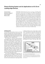
Fig. 2—Schematic of Facility and Equipment for X-Ray<br />
<strong>Inspection</strong> of <strong>Container</strong>s.<br />
In the central inspection zone is X-<strong>ray</strong> inspection equipment for<br />
both horizontal and vertical inspections.<br />
containers includes fixed type for use inside a building<br />
and mobile type used outside in the open. The power<br />
source for X-<strong>ray</strong> equipment used inside is 9 MeV and<br />
for that used outside—because there is no shield and<br />
in order to reduce the space for managing radiation—<br />
is somewhat low energy of 2.5 – 6 MeV.<br />
Fig. 2 shows a typical facility for housing fixedtype<br />
inspection equipment. It has an entrance zone,<br />
an inspection zone, and an exit zone. The inspection<br />
zone is built of concrete, with shielding doors at its<br />
entrance and exit. The concrete structure prevents<br />
radiation leaks to the outside. In fact, the concrete is<br />
thicker in the areas nearest the X-<strong>ray</strong> source and X<strong>ray</strong><br />
detection equipment. The equipment and structures<br />
most closely related to the X-<strong>ray</strong>s are the first shielding<br />
door at the entrance, the second shielding door at the<br />
exit, the X-<strong>ray</strong> source for horizontal inspections, the<br />
X-<strong>ray</strong> detector used for horizontal inspections, the X<strong>ray</strong><br />
source for vertical inspections, and the X-<strong>ray</strong><br />
detector used for vertical inspections. The equipment<br />
used for conveying the trailer inside the structure<br />
includes the No. 1 and No. 2 trailer conveyors.<br />
(2) Flow of inspection procedures<br />
The container trailer driver drives the trailer to a<br />
designated position in the entrance zone, turns off the<br />
ignition, and alights from the vehicle. During the<br />
inspection he/she waits in a special waiting area in the<br />
exit zone. The No. 1 trailer conveyor located in the<br />
inspection structure’s underground area raises the<br />
trailer’s two front wheels in order to pull it forward.<br />
<strong>Cargo</strong> <strong>Container</strong> X-<strong>ray</strong> <strong>Inspection</strong> <strong>Systems</strong> 98<br />
After the first shielding door opens, the trailer is pulled<br />
to the center of the inspection zone and halted. The<br />
No. 1 trailer conveyor is then removed from under the<br />
trailer’s front wheels and returns to its original position<br />
in the entrance zone. At that point, the No. 2 trailer<br />
conveyor takes over by once again raising the trailer’s<br />
two front wheels. After the No. 1 shielding door is<br />
closed the entire container is exposed to X-<strong>ray</strong>s emitted<br />
from two directions relative to the direction the<br />
container is heading, horizontal and vertical. After the<br />
X-<strong>ray</strong> process ends, the No. 2 shielding door opens<br />
and the trailer is pulled into the exit zone. The waiting<br />
driver then boards the trailer and drives it from the<br />
inspection facility.<br />
After the X-<strong>ray</strong>s pass through the container and<br />
are attenuated, a detector detects and measures them.<br />
Depending on how strong the X-<strong>ray</strong>s are the detector<br />
converts them into analog electric signals and transmits<br />
them to an image-processing computer. If the resultant<br />
images show suspicious objects in the container,<br />
additional processing raises the level of contrast<br />
sensitivity and enlarges the objects inside to determine<br />
what they are. The inspection images are transmitted<br />
to an electronic image data server, and the computer<br />
receiving the inspection data transmits the information<br />
to a data server. From there, the horizontal images,<br />
vertical images, and declared information are all<br />
transmitted to an inspector’s computer monitor.<br />
<strong>Container</strong>s are inspected at the rate of 20/h.<br />
(3) Conveying device<br />
The trailer conveyor is fixed to a trailer’s two front<br />
wheels and pulls the trailer forward. As the trailer is<br />
pulled forward at a set speed, the perpendicular X-<strong>ray</strong><br />
beams from the vertical and horizontal X-<strong>ray</strong> sources<br />
pass through the container. The structure of the trailer<br />
conveyor is designed so as not to interfere with the X<strong>ray</strong><br />
inspections. An interlock control prevents the trailer<br />
conveyor from colliding with each other or with the<br />
shielding doors.<br />
(4) Safety equipment<br />
Safety equipment is installed to determine whether<br />
anyone is in the inspection zone, and an interlock<br />
prevents the X-<strong>ray</strong> equipment from operating when<br />
someone is detected. The following safety equipment<br />
is fitted to the facility:<br />
(1) Buzzer for confirming that the driver has alighted<br />
from the trailer<br />
(2) Safety confirmation device (device for confirming<br />
moving objects)<br />
(3) Surveillance camera<br />
(4) Emergency stop switch
X-<strong>ray</strong><br />
sources Trailer conveyor<br />
X-<strong>ray</strong><br />
detectors<br />
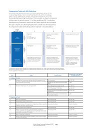
Fig. 3—Schematic of <strong>Container</strong> <strong>Inspection</strong> Equipment Used in<br />
Past.<br />
A trailer conveyor in an underground pit was fixed to a truck’s<br />
front wheels for pulling the truck and trailer forward.<br />
The shielding doors can be opened and closed at<br />
high speeds, but not so fast that they compromise<br />
safety. An interlock prevents X-<strong>ray</strong> exposure when the<br />
shielding doors are open.<br />
(5) Central control equipment<br />
When a container’s cargo is being inspected, the<br />
status of various inspection equipment and devices is<br />
confirmed, such as the opening and closing of the<br />
shielding doors and the starting and stopping of the<br />
conveying device’s operation. Safety is also confirmed<br />
through surveillance cameras, the progress of the<br />
inspection process is monitored, and directions are<br />
issued concerning operation. Central control displays<br />
show the status of inspections and allow the inspectors<br />
to simultaneously check the horizontal and vertical<br />
images and declared data. The image data from<br />
inspections can also be forwarded to other inspection<br />
sections and to the second-stage station where<br />
containers are opened and content of cargo is extracted<br />
and checked individually. Doing so makes it possible<br />
to conduct inspections of individual content of cargo<br />
efficiently. Information related to where suspicious<br />
items might be hidden can also be shared between<br />
inspection stations.<br />
Outline of Latest <strong>Container</strong> <strong>Inspection</strong><br />
Equipment<br />
In the past, as shown in Fig. 3, the front wheels of<br />
a trailer were jacked up and its two front wheels were<br />
fixed to a conveying device in an underground pit. The<br />
trailer conveyor then pulled the trailer forward. Current<br />
equipment, however, as shown in Fig. 4, has the trailer<br />
<strong>Hitachi</strong> Review Vol. 53 (2004), No. 2 99<br />
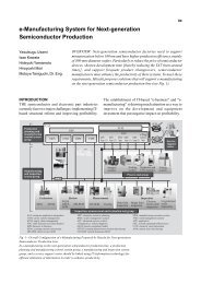
Fig. 4—Latest <strong>Container</strong> Trailer Conveying Device.<br />
This trailer conveyor is aboveground. The trailer driver<br />
positions the two front wheels of the trailer on the dolly and<br />
stops the trailer. After he/she alights, the dolly pulls the trailer<br />
forward.<br />
conveyor moving forward aboveground. The trailer<br />
driver positions the trailer so that its two front wheels<br />
are on a dolly where they are then fixed. After the driver<br />
alights from the trailer the dolly pulls the trailer<br />
forward. The driver boards the trailer again after the<br />
inspection is completed and drives out of the inspection<br />
facility, with the trailer pulling the container across<br />
the dolly.<br />
X-<strong>ray</strong> Equipment for Inspecting <strong>Cargo</strong><br />
(1) X-<strong>ray</strong> DR equipment for inspecting cargo<br />
Compared to X-<strong>ray</strong> DR equipment used for<br />
inspecting containers, X-<strong>ray</strong> DR equipment for<br />
inspecting cargoes is much smaller but can inspect<br />
cargoes 2 m × 2 m in size with about a 2-ton mass. It<br />
uses an X-<strong>ray</strong> tube that emits energy of several hundred<br />
keV. Depending on the type of cargo, the energy can<br />
be adjusted in several steps. There are dual views of<br />
equipment, one for horizontal and the other for vertical<br />
inspections. Brightness can be adjusted, and pseudocolor<br />
and blow-up displays are possible. As shown in<br />
Fig. 5, X-<strong>ray</strong> radiation leaks are prevented through<br />
use of a shielding box and a double-layered lead<br />
curtain.<br />
Because containers hold so much cargo, they are<br />
lifted by forklift, carried to the X-<strong>ray</strong> DR equipment,<br />
and placed on the entrance conveyor. The conveyor<br />
moves at a maximum speed of 18 m/s, allowing clear<br />
X-<strong>ray</strong> DR images even of cargo weighing as much as<br />
2 tons. The equipment couples a small diameter roller<br />
conveyor or a belt conveyor easily penetrated by X<strong>ray</strong>s.
X-<strong>ray</strong> generator<br />
for vertical use<br />
Exit conveyor<br />
Control panel<br />
X-<strong>ray</strong> generator<br />
for horizontal use<br />
<strong>Cargo</strong><br />
X-<strong>ray</strong> detector<br />
for vertical use<br />
X-<strong>ray</strong> detector<br />
for horizontal use<br />
Warning lamp<br />
Lead<br />
curtain<br />
Entrance<br />
conveyor<br />
Fig. 5—X-<strong>ray</strong> DR Equipment for Inspecting <strong>Cargo</strong>.<br />
<strong>Cargo</strong> is inspected vertically and horizontally using X-<strong>ray</strong>s.<br />
(a) Actual component (b) DR image<br />
Fig. 6—Examples of DR Images of Automobile Component.<br />
The DR image shows overlapping, much as X-<strong>ray</strong> images do.<br />
(a) Tomographic image (b) 3D image<br />
Fig. 7—Examples of Tomographic Images of Automobile<br />
Components and 3D Image.<br />
There is no overlapping in the tomographic images; when they<br />
are layered they provide a 3D image.<br />
<strong>Cargo</strong> <strong>Container</strong> X-<strong>ray</strong> <strong>Inspection</strong> <strong>Systems</strong> 100<br />
(a) Actual concrete block (b) 3D image of<br />
steel reinforcements<br />
Fig. 8—Image of Steel Reinforcements Inside Concrete.<br />
Using differences in density, images of the steel reinforcements<br />
inside concrete were extracted and a 3D image was displayed.<br />
(2) X-<strong>ray</strong> CT scanner equipment<br />
Compared to X-<strong>ray</strong> DR inspection equipment, X<strong>ray</strong><br />
CT equipment is superior in one important way.<br />
As shown in Fig. 6, the image of the object being<br />
inspected using X-<strong>ray</strong> DR is overlapped while the<br />
tomographic image, as shown in Fig. 7 (a), displays a<br />
cross-section of the object, thus preventing overlapping<br />
and its accompanying monitoring difficulty. If<br />
tomographic images are layered, as in Fig. 7 (b), the<br />
object can be seen in a 3D image.<br />
Many hospitals today use CT scanners to scan the<br />
human body. The scanners serve a role in early-stage<br />
discovery of disease. At airports, CT equipment is<br />
being used recently in systems for automatically<br />
detecting explosives in checked-in baggage, such as<br />
the EDS (explosive detection system). Relying heavily<br />
on the high-density data characteristic of CT devices,<br />
EDS has the function of identifying explosives. CT<br />
devices are the most effective non-invasive way of<br />
viewing the interior of cargo. Compared to CT devices<br />
used in the medical field or EDS, CT devices used for<br />
scanning cargo require high penetrability and the<br />
source of X-<strong>ray</strong> energy uses a linac of about 1 MeV.<br />
With that amount of energy, as shown in Fig. 8,<br />
even images of the steel reinforcements inside concrete<br />
can be extracted from the dense X-<strong>ray</strong> data and<br />
displayed.<br />
With CT devices, while the object being scanned<br />
is rotated a number of tomographic images are formed<br />
when the X-<strong>ray</strong>s penetrate the object from different<br />
angles. The CT device used with large-size cargo takes<br />
15 seconds to scan and produce one cross-section
image. That is equivalent to the fastest scanning-type<br />
CT device used in industrial field. When using CT<br />
devices already installed, low-speed roller conveyors<br />
are used to prevent cargo 2-meters high or higher from<br />
toppling over. Throughput for those devices is about<br />
10 pieces of large cargo per hour. High-speed<br />
conveyors can be used for normal-size cargo, however,<br />
providing a higher throughput.<br />
<strong>Hitachi</strong>’s CT device for use with cargo has been<br />
rated as providing the world’s fastest performance. It<br />
utilizes industrial-use CT technology. Highly<br />
dependable results can be realized if the technology<br />
in this CT device is used for inspecting containers.<br />
PERFORMANCE OF CONTAINER<br />
INSPECTION EQUIPMENT<br />
The basic performance requirement of equipment<br />
used for inspecting containers is to display a clear<br />
image. Performance concerning three physical criteria<br />
determines the quality of the equipment: penetration,<br />
contrast sensitivity, and resolution. All three criteria<br />
relate closely to the number of photons in an X-<strong>ray</strong>. 1)<br />
Penetration is the most important of the three<br />
physical criteria. In order to increase the number of<br />
photons a source of high-energy X-<strong>ray</strong>s must be<br />
provided.<br />
Contrast sensitivity, the second most important<br />
criterion, plays an especially important role for<br />
differentiating among diverse types of cargo inside a<br />
container. The higher the contrast sensitivity the easier<br />
it is to detect suspicious low-density items. In order to<br />
achieve high contrast sensitivity it is necessary to have<br />
a large number of photons emitted. For that purpose a<br />
wide-area detector is most effective. Another method<br />
used for increasing the number of photons is to<br />
decrease the speed of the object being conveyed —<br />
the container — and to give several pulses of X-<strong>ray</strong>s<br />
per detector.<br />
Resolution, meanwhile, refers to the spatial clarity<br />
of the scanned object. If the object being inspected is<br />
large, for example, it is sufficient to determine only<br />
whether or not it is a suspicious object. For small<br />
objects, however, a high level of resolution is<br />
required 2) . The narrower the pitch of the detector, the<br />
higher the resolution. But that also means fewer<br />
photons, so it becomes a trade-off with the abovementioned<br />
wide-area detector. In that context, <strong>Hitachi</strong><br />
developed two sets of detectors, giving its customers<br />
a choice, depending on use. One set emphasizes<br />
contrast sensitivity, and the other emphasizes<br />
resolution.<br />
<strong>Hitachi</strong> Review Vol. 53 (2004), No. 2 101<br />
SPECIAL CHARACTERISTICS OF<br />
CONTAINER INSPECTION EQUIPMENT<br />
All the components in latest container inspection<br />
equipment are located aboveground, including the<br />
conveying devices. For that reason no underground<br />
digging is needed for installation. That is a particularly<br />
attractive feature since container inspection centers are<br />
located near seaports, often on reclaimed land, so the<br />
less underground digging the better. Also, the dolly<br />
device for pulling the trailer is compact, allowing the<br />
main inspection building also to be compact,<br />
translating into less site area needed. Savings on space<br />
also mean easier expansion of facilities later.<br />
There are two principal types of container<br />
inspections:<br />
(1) One-direction type using horizontal X-<strong>ray</strong>, and<br />
(2) X-<strong>ray</strong>s provide dual views by sending in two<br />
perpendicular beams.<br />
The dual-view method requires underground<br />
digging for the X-<strong>ray</strong> source room. Considering that<br />
cargo is usually stored in containers from the bottom<br />
to the top, a vertical X-<strong>ray</strong> source is set to emit X-<strong>ray</strong>s<br />
from the bottom upward (see Fig. 9).<br />
In order to ensure more throughput, container<br />
inspection equipment in the past used two sets of<br />
conveyance equipment, with one passing off baton<br />
style to the other. More recent equipment, however,<br />
uses a circulatory style so that even during times of<br />
maintenance one set of conveyance equipment enables<br />
inspection of a minimum of 12 containers per hour.<br />
Adding other sets of conveyance equipment will enable<br />
an inspection center to easily reach the world’s highest<br />
level of throughput.<br />
X-<strong>ray</strong>s<br />
Fig. 9—Schematic View of Latest <strong>Container</strong> <strong>Inspection</strong><br />
Equipment.<br />
The trailer carrying the container are pulled forward using an<br />
aboveground conveying device, and the container is inspected<br />
from horizontal and vertical directions.
CONCLUSIONS<br />
As with the inspection of checked-in baggage at<br />
airports, there are several stages in the inspection of<br />
containers at seaports. In the first stage, loaded<br />
containers are inspected as they sit on trailers, with<br />
the emphasis thus on high throughput. In the second<br />
stage, throughout drops as each content of cargo is<br />
inspected to confirm whether or not any suspicious<br />
cargo is in a container. In the final stage, throughput is<br />
low as CT devices are used to detect with high certainty<br />
any suspicious items.<br />
<strong>Cargo</strong> <strong>Container</strong> X-<strong>ray</strong> <strong>Inspection</strong> <strong>Systems</strong> 102<br />
<strong>Hitachi</strong> provides equipment and devices in all three<br />
of the above stages, making it possible to respond fully<br />
with solutions that fit each customer’s objectives.<br />
ACKNOWLEDGMENTS<br />
The authors would like to express their sincere<br />
thanks to the members of Rapiscan Security Products,<br />
Inc. who have produced the most recent container<br />
inspection equipment, and <strong>Hitachi</strong> was able to refer to<br />
Rapiscan’s technology.