Geiger Counter Home-Made
Geiger Counter Home-Made
Geiger Counter Home-Made
Create successful ePaper yourself
Turn your PDF publications into a flip-book with our unique Google optimized e-Paper software.
Clemens Verstappen <strong>Geiger</strong> <strong>Counter</strong> <strong>Home</strong>-<strong>Made</strong><br />
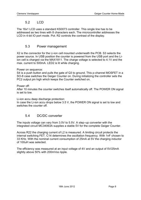
5.2 LCD<br />
The 16x1 LCD uses a standard KS0073 controller. This single line has to be<br />
addressed as two lines with 8 characters each. The microcontroller addresses the<br />
LCD in 4-bit IO port mode. Pot. R2 controls the contrast of the display.<br />
5.3 Power management<br />
X2 is the connector for the Li-ion cell mounted underneath the PCB. S3 selects the<br />
power source. In USB position the counter is powered from the USB port and the Liion<br />
cell is charged via the MAX1811. The charge voltage is selected to 4.1V and the<br />
max. current to 500mA. LED2 is lit while charging.<br />
Power on sequence:<br />
S4 is a push button and pulls the gate of Q3 to ground. This p-channel MOSFET in a<br />
SO-8 case switches the <strong>Geiger</strong> <strong>Counter</strong> on. During initializing the controller sets the<br />
PC2 output pin high which keeps the <strong>Counter</strong> switched on.<br />
Power off:<br />
After 10 minutes the counter switches itself automatically off. The POWER ON signal<br />
is set to low.<br />
Li-ion accu deep discharge protection:<br />
In case the Li-ion accu drops below 3.5 V, the POWER ON signal is set to low and<br />
switches the counter off.<br />
5.4 DC/DC converter<br />
The inputs voltage can vary from 3.5V to 5.5V. A step–up converter with the<br />
integrated circuit MC34063A supplies a stable 5V for the complete <strong>Geiger</strong> <strong>Counter</strong>.<br />
Across R22 the charging current of L2 is measured. A limiting circuit protects the<br />
internal switching FET. C14 determines the oscillation frequency. With 1nF chosen to<br />
33 KHz. With the nominal current consumption of 25mA at 5V the charging inductor<br />
of 100uH was selected.<br />
The efficiency was measured at an input voltage of 4V and an output of 5V/25mA<br />
slightly above 50% with 200mVss ripple.<br />
18th June 2012 Page 8


