Geiger Counter Home-Made
Geiger Counter Home-Made
Geiger Counter Home-Made

You also want an ePaper? Increase the reach of your titles
YUMPU automatically turns print PDFs into web optimized ePapers that Google loves.
Clemens Verstappen <strong>Geiger</strong> <strong>Counter</strong> <strong>Home</strong>-<strong>Made</strong><br />
<strong>Geiger</strong> <strong>Counter</strong> <strong>Home</strong>-<strong>Made</strong><br />
Documentation<br />
Bill of Material<br />
Parts<br />
Keywords: activity, Atmel AVR microcontroller, ATMega, beta gamma<br />
radiation, CTC-5, equivalent dose, geiger tube, GM counter, radiation,<br />
STS-5,<br />
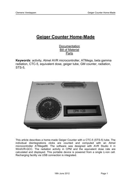
This article describes a home-made <strong>Geiger</strong> <strong>Counter</strong> with a CTC-5 (STS-5) tube. The<br />
individual disintegrations clicks are counted and computed with an Atmel<br />
microcontroller ATMega88. The software was designed with AVR Studio 4 in<br />
WinAVR-GCC. The radiation activity in CPM and the equivalent dose rate are<br />
calculated and displayed. This portable device is powered from a single Li-ion cell.<br />
Recharging facility via USB connection is integrated.<br />
18th June 2012 Page 1
Clemens Verstappen <strong>Geiger</strong> <strong>Counter</strong> <strong>Home</strong>-<strong>Made</strong><br />
Contents<br />
1 Radiation basics<br />
2 Features<br />
3 Block diagram<br />
4 <strong>Geiger</strong> tube CTC-5<br />
4.1 Schematic high voltage generation<br />
5 Schematic microcontroller<br />
5.1 Analog input and output signals<br />
5.2 LCD<br />
5.3 Power management<br />
5.4 DC/DC converter<br />
6 Construction on the perfboard<br />
7 Software<br />
7.1 Interrupts<br />
7.2 Timer<br />
7.3 A/D converters, average and display<br />
7.4 Power related functions<br />
8.0 Calibration with a professional equivalent dose meter<br />
9.0 Parts and distributers<br />
10. Appendix and abbreviations<br />
10.1 References<br />
18th June 2012 Page 2
Clemens Verstappen <strong>Geiger</strong> <strong>Counter</strong> <strong>Home</strong>-<strong>Made</strong><br />
1 Radiation basics<br />
The human being does not have any sense for radiation. To avoid being harmed by<br />
radioactivity, measurement is the only option. The measurement of physical units<br />
allows the possibility to determine the medical or biological effects, the destruction of<br />
human tissue and DNA. The likeliness of suffering from leukaemia can be calculated.<br />
Through the past century plenty of units have been introduced. Confusion exist about<br />
these units. The proper use of conversion tables is difficult.<br />
The SI system (International System of Units [8]) needs only three units for a<br />
comprehensive description:<br />
Quantity name Unit name Quantity symbol Unit<br />
Radioactivity Becquerel Bq s−1<br />
Absorbed dose Gray Gy J/kg<br />
Equivalent dose Sievert Sv J/kg<br />
All other units are related or old and should not be used any more.<br />
Brief explanation:<br />
BECQUEREL: means the number of disintegration per second.<br />
Example: If one million uranium atoms disintegrate in one second<br />
this equals 1,000,000 Becquerel or 1MBq.<br />
GRAY: for the absorbed dose.<br />
The energy (J) which is absorbed by the mass (kg)<br />
SIEVERT: for the equivalent dose.<br />
This is mainly medical related and indicates the hazard the radiation<br />
causes to the human body. If the absorbed dose and the type of<br />
radiation are known, the equivalent dose can be calculated.<br />
For Gray and Sievert the dose rate is mostly used. This is the amount of absorbed<br />
dose or equivalent dose per time interval. Common intervals are hour or year e.g.<br />
uSv/h or mSv/a.<br />
18th June 2012 Page 3
Clemens Verstappen <strong>Geiger</strong> <strong>Counter</strong> <strong>Home</strong>-<strong>Made</strong><br />
2.0 Features<br />
Schematics around counter tubes are mainly related to the high voltage generation.<br />
Examples are widely spread in the net. A special issue of this counter is beside the<br />
generation of the high voltage, the microcontroller computing the clicks and display<br />
the data on an LCD. Here the main features of this design:<br />
� Microcontroller ATMega88, Software in AVR-GCC<br />
� Software controlled speaker pulse width “click”<br />
� Display of CPM and nSv/h<br />
� Display of Li-ion and tube voltage<br />
� Charging facility from a USB port<br />
� Step up converter to a stable 5.0V<br />
� Auto-power-off after 10min<br />
� Li-ion accu deep discharge protection<br />
� PWM-output for an external analog meter<br />
Nevertheless a stable 5V is useful in combination with a controller and an LCD.<br />
Unfortunately the contrast varies with the supplying voltages. The usage of a<br />
standard 3.7 V Li-ion rechargeable battery is a solution to the portability and capacity.<br />
The annoying effect of self-discharging like regular nickel metalhydrid accu is<br />
avoided by usage of li-ion technology. Recharging is supplied with a simple USB<br />
cable from any computer interface.<br />
18th June 2012 Page 4
Clemens Verstappen <strong>Geiger</strong> <strong>Counter</strong> <strong>Home</strong>-<strong>Made</strong><br />
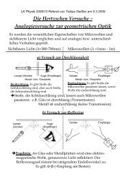
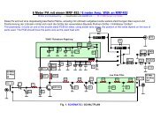
3 Block diagram<br />
The “click” signal of the <strong>Geiger</strong> tube triggers an interrupt input of the controller. An<br />
output of the controller feeds the speaker. The pulse length is fixed by software. Four<br />
modes of display are selectable with the toggle mode switch:<br />
1) CPM radiation activity in counts per minute<br />
2) nSv/h radiation dose equivalent in nano -sievert per hour<br />
3) mV voltage of battery<br />
4) HV voltage of tube high voltage<br />
The “Battery / USB” selects the source of power. The push button “Power ON” turns<br />
the counter on. In case a USB connection is made, the li-ion battery is charged<br />
automatically. Another output pin of the controller drives a PWM signal for an analog<br />
instrument. This may be connected externally. See the simplified block diagram in<br />
figure 1.<br />
1<br />
2<br />
3<br />
4<br />
A B C D E F<br />
<strong>Geiger</strong> Tube<br />
USB<br />
Charge<br />
Li-ion cell<br />
800mAh<br />
Power ON Toggle Mode Speaker<br />
Battery / USB<br />
ATMega 88<br />
Microcontroller<br />
Up Converter<br />
3,7 / 5V<br />
Änderungen: Datum:<br />
Datum: Name: gez.:<br />
gepr.:<br />
16.04.2012<br />
Name:<br />
Verstappen<br />
Block Diagram<br />
Figure 1: Block diagram of the <strong>Geiger</strong> <strong>Counter</strong> <strong>Home</strong>-<strong>Made</strong><br />
1 Line LCD Display<br />
Meter<br />
Bezeichnung:<br />
<strong>Geiger</strong> <strong>Counter</strong> <strong>Home</strong>-<strong>Made</strong><br />
Zeichnungs-Nr.:<br />
uSv/h<br />
Blattzahl:<br />
1<br />
Blatt-NR.:<br />
1<br />
18th June 2012 Page 5
Clemens Verstappen <strong>Geiger</strong> <strong>Counter</strong> <strong>Home</strong>-<strong>Made</strong><br />
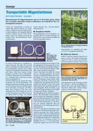
4 Schematic high voltage generation<br />
Figure 2: Schematic of the high voltage generation<br />
The advantage of this high voltage circuit is the very low supply current consumption<br />
and the independence of the supplying voltage. R9 is the anode resistor for the tube.<br />
C2 and C3 are storage capacitors for high voltage. R4 and C1 determine the on-time<br />
(30us), C1 and R3 the off-time (3ms). During the on pulse, the current in the coil<br />
increases with about 1mA / ms. R2 and the Ube limits the current at 25mA and<br />
switches the Q2 off. In this moment the L1 in combination with stray capacitance<br />
creates a 1/2 sine voltage wave about 2us long and >400V high. This is passed by<br />
D2 to the storage capacitors C3 & C4.<br />
This is an unwanted effect when switching a relay coil with a transistor. This spike<br />
destroys the transistor if a freewheeling diode across the coil is not implemented.<br />
For a more detailed description see John Giametti [2] and Tom Napier [1].<br />
In case the <strong>Geiger</strong> Tube detects radiation disintegrations, the current increases for<br />
about 200us. This pulses are amplified an inverted by transistors Q4. These CLICKS<br />
feed the interrupt input of the controller.<br />
18th June 2012 Page 6
Clemens Verstappen <strong>Geiger</strong> <strong>Counter</strong> <strong>Home</strong>-<strong>Made</strong><br />
4.1 <strong>Geiger</strong> tube CTC-5<br />
CTC-5 type is Russian production and sensitive to beta and gamma radiation. For a<br />
proper indication the tube should be operated with 400V. See appendix for detailed<br />
data.<br />
The tube detects about 25 pulses per minute at normal background equivalent to<br />
approximately 0.1 uSv / h.<br />
Verification of CPM was check with square waveform from a signal generator into the<br />
R/C combination of the controller interrupt input. A 50 Hz signal resulted in a display<br />
of 3000 cpm. Total satisfying result.<br />
Check of maximum. A signal of 250Hz resp. 15.000 CPM hits the limit of the counter.<br />
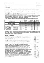
5 Schematic microcontroller<br />
The click signal from the high voltage part is active low. On the way to the controller<br />
interrupt input it passes a low pass filter R10 and C5. R13 and R14 are the voltage<br />
divider for the 400V high voltage. The ratio is 1GΩ by 1MΩ. The high values are<br />
necessary since the high voltage is of very high impedance. Lower values would<br />
affect the measurement accuracy. The HV signal is connected to the A/D converter<br />
ADC1 of the controller. The battery voltage 3.7V is applied to the ADC0 with a divider<br />
of R11 and R12. Since the internal reference voltage for the A/D converter is 1.1 volt,<br />
a reduction is necessary. A software calibration value will compensate for this.<br />
S2 is the pushbutton for the display mode. The interrupt input INT1 is falling edge<br />
sensitive. The RC combination debounces the switch.<br />
The PB2 output drives the SPEAKER signal. T1 decouples and amplifies for the 8Ω<br />
speaker. The timer2 output compare (OC1A) pin is the PWM signal for the analog<br />
meter. R4 limits the maximum current. For other than 100uA full scale meters the<br />
value has to be adjusted. With a current of 100uA full scale the instrument is<br />
calibrated to about 4000 CPM respectively 22000nSv/h. For higher currents an<br />
additional stage is necessary.<br />
LED1 flashes with 0.5 Hz. A compare match of timer1 toggles the LED and the flag<br />
for the main program loop.<br />
S3 selects the power source either from the Li-ion cell or from an USB interface. In<br />
this case the battery charges.<br />
X1 is the ISP (in circuit programming) connector.<br />
CAUTION: When programming, keep power button pressed. During programming the<br />
reset pin is kept low and the controller switches it own power off. See figure 3.<br />
18th June 2012 Page 7
Clemens Verstappen <strong>Geiger</strong> <strong>Counter</strong> <strong>Home</strong>-<strong>Made</strong><br />
5.2 LCD<br />
The 16x1 LCD uses a standard KS0073 controller. This single line has to be<br />
addressed as two lines with 8 characters each. The microcontroller addresses the<br />
LCD in 4-bit IO port mode. Pot. R2 controls the contrast of the display.<br />
5.3 Power management<br />
X2 is the connector for the Li-ion cell mounted underneath the PCB. S3 selects the<br />
power source. In USB position the counter is powered from the USB port and the Liion<br />
cell is charged via the MAX1811. The charge voltage is selected to 4.1V and the<br />
max. current to 500mA. LED2 is lit while charging.<br />
Power on sequence:<br />
S4 is a push button and pulls the gate of Q3 to ground. This p-channel MOSFET in a<br />
SO-8 case switches the <strong>Geiger</strong> <strong>Counter</strong> on. During initializing the controller sets the<br />
PC2 output pin high which keeps the <strong>Counter</strong> switched on.<br />
Power off:<br />
After 10 minutes the counter switches itself automatically off. The POWER ON signal<br />
is set to low.<br />
Li-ion accu deep discharge protection:<br />
In case the Li-ion accu drops below 3.5 V, the POWER ON signal is set to low and<br />
switches the counter off.<br />
5.4 DC/DC converter<br />
The inputs voltage can vary from 3.5V to 5.5V. A step–up converter with the<br />
integrated circuit MC34063A supplies a stable 5V for the complete <strong>Geiger</strong> <strong>Counter</strong>.<br />
Across R22 the charging current of L2 is measured. A limiting circuit protects the<br />
internal switching FET. C14 determines the oscillation frequency. With 1nF chosen to<br />
33 KHz. With the nominal current consumption of 25mA at 5V the charging inductor<br />
of 100uH was selected.<br />
The efficiency was measured at an input voltage of 4V and an output of 5V/25mA<br />
slightly above 50% with 200mVss ripple.<br />
18th June 2012 Page 8
Clemens Verstappen <strong>Geiger</strong> <strong>Counter</strong> <strong>Home</strong>-<strong>Made</strong><br />
Figure 3: Schematic microcontroller<br />
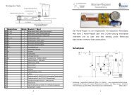
6 Construction on a perfboard<br />
Components are easy to identify, see figure 2. A standard perfboard of 100mm by<br />
160mm (eurocard) was used. All components are fixed onto the PCB, nothing is<br />
attached to the enclosure.<br />
A 6.3 x 32mm fuse holder avoids soldering the contact of the <strong>Geiger</strong> tube. The left 8<br />
pin IC is the dc/dc converter the right one is the timer for high voltage generation.<br />
The red resistor (1GΩ, 5watts) belongs to the high voltage divider. Underneath the<br />
LCD is the ATMega88 microcontroller located.<br />
On the soldering side are integrated circuits for charging the li-ion cell and the FET<br />
as power switch, both SMD devices. See photo#3. Figure 4 shows the socket of the<br />
controller before the LCD was mounted.<br />
18th June 2012 Page 9
Clemens Verstappen <strong>Geiger</strong> <strong>Counter</strong> <strong>Home</strong>-<strong>Made</strong><br />
Figure 4: Photo component side<br />
Figure 5: Photo PCB, SMD components on the solder side<br />
18th June 2012 Page 10
Clemens Verstappen <strong>Geiger</strong> <strong>Counter</strong> <strong>Home</strong>-<strong>Made</strong><br />
Figure 6: Photo PCB, Controller underneath LCD<br />
18th June 2012 Page 11
Clemens Verstappen <strong>Geiger</strong> <strong>Counter</strong> <strong>Home</strong>-<strong>Made</strong><br />
7 Software<br />
The source code was designed with Atmel AVR Studio 4 in WinAVR-GCC. The<br />
software is under GNU license, for details see header of source code. The lcd.h from<br />
Peter Fleury made the control of the LCD easy. The intension was to keep the source<br />
code as simple as possible. Float variables were not used, numbers on the LCD<br />
were kept in integers. Here is plenty of room for modifications and improvements.<br />
Mainly interrupt routines were used to control the program. All three timers of the<br />
ATMega88 are used.<br />
7.1 Interrupts<br />
INT0<br />
In case radiation disintegration is detected by the tube, the falling edge of the signal<br />
“COUNTER_TUBE” generates an interrupt on INT0 (SIGNAL (INT0_vect)). In the<br />
corresponding routine the output signal “SPEAKER” is set to high. Timer0 starts<br />
immediately and this event increases the counter.<br />
INT1<br />
A falling edge on the INT1 inputs toggles between the four display modes. In the<br />
interrupt routine (SIGNAL (INT1_vect)) the display mode is increased.<br />
7.2 Timer<br />
Timer0 determines the length of the dc signal of the “SPEAKER.” A compare match<br />
interrupt on timer0 (SIGNAL (TIMER0_COMPA_vect)) switches the dc off again. The<br />
prescaler of 1024 and 20MHz oscillator frequency, the timer increases in steps of<br />
about 51us. The compare match is programmed in OCR0A to 4 produces a nice click<br />
of 200us.<br />
Timer1 generates a compare match interrupt (SIGNAL(TIMER1_COMPA_vect)).<br />
This generates the flag for the main program loop. Only once per second all<br />
calculations are performed and the LCD is updated.<br />
Timer2 produces the PWM signal for the external connected analog meter.<br />
18th June 2012 Page 12
Clemens Verstappen <strong>Geiger</strong> <strong>Counter</strong> <strong>Home</strong>-<strong>Made</strong><br />
7.3 A/D converters, average and display<br />
In the main loop every second the numbers of clicks are copied into the<br />
average_array[]. Each second this array is shifted by one element. The average of all<br />
elements in a time frame of 15 seconds, multiplied by 4, results into the desired CPM.<br />
The ADC0 is connected to the battery voltage of the Li-ion cell, the ADC1 to the high<br />
voltage of the tube. Each second an A/D conversion for one of these values is<br />
started, the third value is stable and used. A calibration value of 67/13 for battery<br />
A/D gives the voltage in mV. The A/D value of the HV corresponds directly in volts.<br />
7.4 Power related functions<br />
The usage of a Li-ion cell makes the monitoring of the voltage mandatory. A<br />
complete discharge damages the cell. In case a value of less than 3.5V is detected<br />
the <strong>Geiger</strong> counter switches itself off. An auto power off function switches off after 10<br />
minutes as well.<br />
18th June 2012 Page 13
Clemens Verstappen <strong>Geiger</strong> <strong>Counter</strong> <strong>Home</strong>-<strong>Made</strong><br />
8.0 Calibration with a professional equivalent dose meter<br />
A reference measurement with a professional fully calibrated equivalent dose rate<br />
meter (Berthold TOL-F) was made in order to verify the accuracy of activity<br />
measurement. More over an attempt was made to find a calibration value in order to<br />
indicate the equivalent dose in nSv/h. The latter can only be a rough reference since<br />
the type of sensor is different. The accurate value depends on a variety of parameter<br />
e.g. tube high voltage.<br />
For the first test the probe measured the surface activity of a small piece of broken<br />
ceramic plate with uranium glaze [7]. The instrument read 36 IPS (or 2340 CPM) See<br />
figure 7 and 8. The same shard was held at the same distance above the <strong>Geiger</strong><br />
counters tube. The reading was 2196CPM. This was an unexpected good match.<br />
In the second step the dose rate equivalent was selected on the TOL-F. The meter<br />
indicated 13uSv/h. This resulting calibration value of 0.33 uSv/h per one IPS was<br />
taken over from the TOL-F. Refer to chapter 10. Appendix and abbreviations<br />
Figure 7: left, <strong>Geiger</strong> <strong>Counter</strong> <strong>Home</strong>-<strong>Made</strong> and professional equivalent dose meter<br />
Figure 8: right, The probe and a broken piece of ceramic plate<br />
18th June 2012 Page 14
Clemens Verstappen <strong>Geiger</strong> <strong>Counter</strong> <strong>Home</strong>-<strong>Made</strong><br />
9.0 Parts and distributers<br />
Distributor: Reichelt Elektronik [4]<br />
1 ATMEGA 88-20 PU ATMega AVR-RISC-Controller<br />
1 LCD 161A LCD-MODUL 16X1<br />
1 MC 34063 A Schaltregler, DIP-8<br />
1 MAX 1811 ESA MAXIM-IC, SO-8 // Laden von LiIon Akkus S<br />
1 ICM 7555 Timer, DIP-8 = ILC 555 siehe Datenblatt<br />
1 IRF 7220 Leistungs-MOSFET P-Ch SO-8 12V 11A<br />
1 MPSA 44 Transistor NPN TO-92 400V 0,3A 0,625W<br />
1 MR 856 Fast-Recovery-Gleichrichterdiode, DO27,600V,3A<br />
1 MUR 160 Ultrafast Diode, DO-15 / DO-204AC, 600V, 1A<br />
2 2N 2222 Transistor NPN TO-18 60V 0,8A 0,5W<br />
1 1N 4148 Planar Epitaxial Schaltdiode, DO35, 100V, 0,15A<br />
1 VAP VFL002 LiION Camcorder-Akku 3,7V 1050mAh<br />
1 L-07HCP 100µ Stehende-Induktivität, 07HCP, Ferrit, 100µ<br />
1 L-07HCP 10M Stehende-Induktivität, 07HCP, Ferrit, 10m<br />
1 64Y-100 Präzisionspoti. 25 Gänge, stehend, 100 Ohm<br />
1 VIS K 50-8 VISATON Breitbandspeaker, 5cm, IP 65, Metall<br />
1 GEH EFG 1A Euro-ALU-Flachgehäuse 168 x 113,5 x 31 mm<br />
1 LCD FRONT 1 LCD-RAHMEN für 1x 16 Zeichen, schwarz<br />
1 AKL 182-02 Wannenstecker für AKL 169, 2-pol, RM3,5<br />
1 GS 28P-S IC-Sockel, 28-polig, superflach, gedreht, schmal<br />
2 GS 8P IC-Sockel, 8-polig, superflach, gedreht, vergold.<br />
1 TASTER 3305B Kurzhubtaster 6,6x7,4mm,Höhe:8,35mm,12V,horiz<br />
1 USB BW USB-Einbaubuchse, Serie B, gew., Printmontage<br />
1 PICO 1,0A Feinsicherung, Picofuse, flink, 1,0A<br />
1 UP 832EP Lochrasterplatine, Epoxyd, 160x100m<br />
1 PL 137000 Sicherungshalter, 6,3x32mm, max. 6,3A-250V<br />
Distributor: Conrad Elektronik [9]<br />
1 Miniatur-Print-Taster (L x B x H) 20 x 10 x 7 mm Schwarz gerade 24 V 0,01 A<br />
1 Schiebeschalter 2 x Ein/Ein/Ein 50 V 0,3 A<br />
Source for 1GΩ:<br />
1 R14 GΩ Resistor amazon, search:<br />
“1G Ohm 3w 5% Resistance Glaze High Voltage Resistor”<br />
18th June 2012 Page 15
Clemens Verstappen <strong>Geiger</strong> <strong>Counter</strong> <strong>Home</strong>-<strong>Made</strong><br />
10. Appendix and Abbreviation<br />
Technical characteristics of <strong>Geiger</strong>-Mueller <strong>Counter</strong> STS-5 [3]:<br />
Radiation Source - Cs;<br />
Gamma radiation sensitivity: MED - 0.28mkR∙s-1;<br />
Operating voltage - 390V;<br />
Power bills start - 280V-330V;<br />
Length of the counting characteristics - not less than 80 V;<br />
The slope of the counting data - no more than 0.125%/V;<br />
Own background - not more than 0.45 s-1 ;<br />
The maximum operating MED - 2500 s-1, 30mkR∙s-1,k.n.± 20%;<br />
The maximum permissible MED dose - at least 50R∙ h-1 ;<br />
Dimensions - 12x12x110mm;<br />
Weight - 10g.<br />
Berthold TOL-F equivalent dose rate meter:<br />
Measurement Instrument: Dose Rate Power Meter<br />
Type: TOL/F LB1320<br />
Manufacturer: Berthold Technologies GmbH& Co.KG<br />
Detector: LB1321<br />
Measuring Range:<br />
Low dose range: 0.1uSv/h – 10mSv/h<br />
High dose range: 10mSv/h – 100.0Sv/h<br />
Energy range: 10 keV – 7 MeV ±30%<br />
Calibration Factor: 0.33 uSv/h / ips<br />
Abbreviations:<br />
CPM counts per minute<br />
nSv / h equivalent dose rate in nano sievert per hour<br />
IPS Impulse per second<br />
R Roentgen<br />
Gy Gray<br />
eV Electron volt<br />
18th June 2012 Page 16
Clemens Verstappen <strong>Geiger</strong> <strong>Counter</strong> <strong>Home</strong>-<strong>Made</strong><br />
10.1 References<br />
[1] Napier, Tom. Biassing G-M Tubes Isn´t So Hard, Nuts&Volts January 2004, [1]<br />
www.nutsvolts.com<br />
[2] DIY <strong>Geiger</strong> <strong>Counter</strong><br />
http://sites.google.com/site/diygeigercounter/<br />
[3] Giametti, J.: DIY<strong>Geiger</strong><strong>Counter</strong><br />
http://www.gstube.com/data/4540/<br />
[4] Reichelt Elektronik GmbH & Co KG, Tel. +49 44 22 - 9 55-3 33,<br />
http://www.reichelt.de: standard components.<br />
[5] Wagner, D. , DJ7BU: Selbstbau eines <strong>Geiger</strong>zählers. Funkamateur 61 (2012) H. 2, S.<br />
154-157; http://www.funkamateur.de<br />
[6] BERTHOLD TECHNOLOGIES GmbH & Co. KG, Tel. +49 7081 177-0<br />
http://www.berthold.com<br />
[7] Pintschka , F.: Uranglazuren<br />
http://www.frank-pintschka.de/3.html<br />
[8] International System of Units<br />
http://en.wikipedia.org/wiki/International_System_of_Units<br />
http://de.wikipedia.org/wiki/Internationales_Einheitensystem<br />
[9] Conrad Electronic SE, Tel.: 0180 5 312111<br />
http://www.conrad.de/ce/<br />
18th June 2012 Page 17