PET/CT Imaging Artifacts* - Journal of Nuclear Medicine Technology
PET/CT Imaging Artifacts* - Journal of Nuclear Medicine Technology
PET/CT Imaging Artifacts* - Journal of Nuclear Medicine Technology

You also want an ePaper? Increase the reach of your titles
YUMPU automatically turns print PDFs into web optimized ePapers that Google loves.
<strong>PET</strong>/<strong>CT</strong> <strong>Imaging</strong> <strong>Artifacts*</strong><br />
Waheeda Sureshbabu, CNMT, <strong>PET</strong> 1 ; and Osama Mawlawi, PhD 2<br />
1<strong>Nuclear</strong> <strong>Medicine</strong>, M.D. Anderson Cancer Center, Houston, Texas; and 2<strong>Imaging</strong> Physics, M. D. Anderson Cancer Center, Houston,<br />
Texas<br />
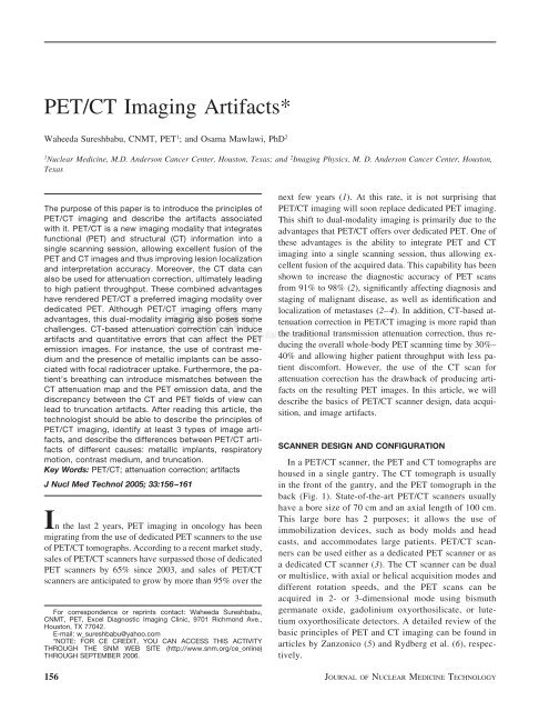
The purpose <strong>of</strong> this paper is to introduce the principles <strong>of</strong><br />
<strong>PET</strong>/<strong>CT</strong> imaging and describe the artifacts associated<br />
with it. <strong>PET</strong>/<strong>CT</strong> is a new imaging modality that integrates<br />
functional (<strong>PET</strong>) and structural (<strong>CT</strong>) information into a<br />
single scanning session, allowing excellent fusion <strong>of</strong> the<br />
<strong>PET</strong> and <strong>CT</strong> images and thus improving lesion localization<br />
and interpretation accuracy. Moreover, the <strong>CT</strong> data can<br />
also be used for attenuation correction, ultimately leading<br />
to high patient throughput. These combined advantages<br />
have rendered <strong>PET</strong>/<strong>CT</strong> a preferred imaging modality over<br />
dedicated <strong>PET</strong>. Although <strong>PET</strong>/<strong>CT</strong> imaging <strong>of</strong>fers many<br />
advantages, this dual-modality imaging also poses some<br />
challenges. <strong>CT</strong>-based attenuation correction can induce<br />
artifacts and quantitative errors that can affect the <strong>PET</strong><br />
emission images. For instance, the use <strong>of</strong> contrast medium<br />
and the presence <strong>of</strong> metallic implants can be associated<br />
with focal radiotracer uptake. Furthermore, the patient’s<br />
breathing can introduce mismatches between the<br />
<strong>CT</strong> attenuation map and the <strong>PET</strong> emission data, and the<br />
discrepancy between the <strong>CT</strong> and <strong>PET</strong> fields <strong>of</strong> view can<br />
lead to truncation artifacts. After reading this article, the<br />
technologist should be able to describe the principles <strong>of</strong><br />
<strong>PET</strong>/<strong>CT</strong> imaging, identify at least 3 types <strong>of</strong> image artifacts,<br />
and describe the differences between <strong>PET</strong>/<strong>CT</strong> artifacts<br />
<strong>of</strong> different causes: metallic implants, respiratory<br />
motion, contrast medium, and truncation.<br />
Key Words: <strong>PET</strong>/<strong>CT</strong>; attenuation correction; artifacts<br />
J Nucl Med Technol 2005; 33:156–161<br />
In the last 2 years, <strong>PET</strong> imaging in oncology has been<br />
migrating from the use <strong>of</strong> dedicated <strong>PET</strong> scanners to the use<br />
<strong>of</strong> <strong>PET</strong>/<strong>CT</strong> tomographs. According to a recent market study,<br />
sales <strong>of</strong> <strong>PET</strong>/<strong>CT</strong> scanners have surpassed those <strong>of</strong> dedicated<br />
<strong>PET</strong> scanners by 65% since 2003, and sales <strong>of</strong> <strong>PET</strong>/<strong>CT</strong><br />
scanners are anticipated to grow by more than 95% over the<br />
For correspondence or reprints contact: Waheeda Sureshbabu,<br />
CNMT, <strong>PET</strong>, Excel Diagnostic <strong>Imaging</strong> Clinic, 9701 Richmond Ave.,<br />
Houston, TX 77042.<br />
E-mail: w_sureshbabu@yahoo.com<br />
*NOTE: FOR CE CREDIT, YOU CAN ACCESS THIS A<strong>CT</strong>IVITY<br />
THROUGH THE SNM WEB SITE (http://www.snm.org/ce_online)<br />
THROUGH SEPTEMBER 2006.<br />
next few years (1). At this rate, it is not surprising that<br />
<strong>PET</strong>/<strong>CT</strong> imaging will soon replace dedicated <strong>PET</strong> imaging.<br />
This shift to dual-modality imaging is primarily due to the<br />
advantages that <strong>PET</strong>/<strong>CT</strong> <strong>of</strong>fers over dedicated <strong>PET</strong>. One <strong>of</strong><br />
these advantages is the ability to integrate <strong>PET</strong> and <strong>CT</strong><br />
imaging into a single scanning session, thus allowing excellent<br />
fusion <strong>of</strong> the acquired data. This capability has been<br />
shown to increase the diagnostic accuracy <strong>of</strong> <strong>PET</strong> scans<br />
from 91% to 98% (2), significantly affecting diagnosis and<br />
staging <strong>of</strong> malignant disease, as well as identification and<br />
localization <strong>of</strong> metastases (2–4). In addition, <strong>CT</strong>-based attenuation<br />
correction in <strong>PET</strong>/<strong>CT</strong> imaging is more rapid than<br />
the traditional transmission attenuation correction, thus reducing<br />
the overall whole-body <strong>PET</strong> scanning time by 30%–<br />
40% and allowing higher patient throughput with less patient<br />
discomfort. However, the use <strong>of</strong> the <strong>CT</strong> scan for<br />
attenuation correction has the drawback <strong>of</strong> producing artifacts<br />
on the resulting <strong>PET</strong> images. In this article, we will<br />
describe the basics <strong>of</strong> <strong>PET</strong>/<strong>CT</strong> scanner design, data acquisition,<br />
and image artifacts.<br />
SCANNER DESIGN AND CONFIGURATION<br />
In a <strong>PET</strong>/<strong>CT</strong> scanner, the <strong>PET</strong> and <strong>CT</strong> tomographs are<br />
housed in a single gantry. The <strong>CT</strong> tomograph is usually<br />
in the front <strong>of</strong> the gantry, and the <strong>PET</strong> tomograph in the<br />
back (Fig. 1). State-<strong>of</strong>-the-art <strong>PET</strong>/<strong>CT</strong> scanners usually<br />
have a bore size <strong>of</strong> 70 cm and an axial length <strong>of</strong> 100 cm.<br />
This large bore has 2 purposes; it allows the use <strong>of</strong><br />
immobilization devices, such as body molds and head<br />
casts, and accommodates large patients. <strong>PET</strong>/<strong>CT</strong> scanners<br />
can be used either as a dedicated <strong>PET</strong> scanner or as<br />
a dedicated <strong>CT</strong> scanner (3). The <strong>CT</strong> scanner can be dual<br />
or multislice, with axial or helical acquisition modes and<br />
different rotation speeds, and the <strong>PET</strong> scans can be<br />
acquired in 2- or 3-dimensional mode using bismuth<br />
germanate oxide, gadolinium oxyorthosilicate, or lutetium<br />
oxyorthosilicate detectors. A detailed review <strong>of</strong> the<br />
basic principles <strong>of</strong> <strong>PET</strong> and <strong>CT</strong> imaging can be found in<br />
articles by Zanzonico (5) and Rydberg et al. (6), respectively.<br />
156 JOURNAL OF NUCLEAR MEDICINE TECHNOLOGY
<strong>CT</strong>-BASED ATTENUATION CORRE<strong>CT</strong>ION<br />
One main advantage <strong>of</strong> a <strong>PET</strong>/<strong>CT</strong> scanner is that it uses<br />
the <strong>CT</strong> image for attenuation correction <strong>of</strong> the <strong>PET</strong> data<br />
rather than relying on a rotating transmission rod source.<br />
Use <strong>of</strong> the <strong>CT</strong> scan reduces the total <strong>PET</strong> acquisition time<br />
and improves the precision <strong>of</strong> the attenuation correction<br />
factors (3). Upon completion <strong>of</strong> the <strong>CT</strong> scan, the <strong>CT</strong> attenuation<br />
coefficients corresponding to the different tissue<br />
types are mapped to their respective <strong>PET</strong> energies (511<br />
keV) to generate a <strong>PET</strong> attenuation correction map. Different<br />
conversion methods are currently used to perform this<br />
task. One method, suggested by Kinahan et al. (7), segments<br />
the <strong>CT</strong> images to different tissue types and then scales each<br />
<strong>of</strong> the tissues to its corresponding <strong>PET</strong> values using predefined<br />
scaling factors (7). Another method, adopted by GE<br />
Healthcare, uses bilinear transformation, which can also be<br />
viewed as a combination <strong>of</strong> segmentation and scaling technique<br />
(8,9). In either method, the mapping is unique for the<br />
average <strong>CT</strong> peak kilovoltage used. Use <strong>of</strong> this mapping<br />
process on <strong>CT</strong> images acquired with different energies<br />
would require different lookup tables. During attenuation<br />
correction, the choice <strong>of</strong> the proper lookup table is vital to<br />
the technologist; the map is directly selected based on the<br />
<strong>CT</strong> peak kilovoltage used during data acquisition.<br />
IMAGE ACQUISITION<br />
A <strong>PET</strong>/<strong>CT</strong> imaging protocol usually calls for acquisition<br />
<strong>of</strong> a <strong>CT</strong> scout scan first, followed by a <strong>CT</strong> scan and a <strong>PET</strong><br />
scan. The <strong>CT</strong> scout scan serves as an anatomic reference for<br />
the <strong>PET</strong>/<strong>CT</strong> scan. The technologist uses the scout scan to<br />
define the starting and ending locations <strong>of</strong> the actual <strong>CT</strong> and<br />
<strong>PET</strong> acquisitions. The <strong>CT</strong> scan is acquired over the range<br />
VOLUME 33, NUMBER 3, SEPTEMBER 2005<br />
defined on the scout scan. <strong>CT</strong> scans are usually obtained<br />
using 100–140 kVp at various amperages, depending on the<br />
imaging protocol. Upon completion <strong>of</strong> the <strong>CT</strong> scan, the bed<br />
is automatically moved to position the patient in the field <strong>of</strong><br />
view <strong>of</strong> the <strong>PET</strong> scanner. The patient is positioned so that<br />
the <strong>PET</strong> scan matches the same anatomic extent imaged<br />
during the <strong>CT</strong> acquisition. <strong>PET</strong> emission data are then<br />
acquired for 3–5 min per bed position covering the area <strong>of</strong><br />
interest. The <strong>PET</strong> raw data are then reconstructed using the<br />
<strong>CT</strong> images for attenuation correction. <strong>CT</strong> scans are usually<br />
reconstructed in a 512 � 512 image matrix, whereas <strong>PET</strong><br />
images are reconstructed in a matrix <strong>of</strong> 128 � 128. Upon<br />
reconstruction, both the <strong>PET</strong> images and the <strong>CT</strong> images are<br />
displayed side by side and overlaid (fused) (Fig. 2). This<br />
process can be done either on the same acquisition computer<br />
or on a different workstation, depending on the manufacturer.<br />
IMAGING ARTIFA<strong>CT</strong>S<br />
FIGURE 1. Current commercial <strong>PET</strong>/<strong>CT</strong><br />
scanners from 3 vendors: Discovery ST (GE<br />
Healthcare) (A), Biograph Sensation 16 (Siemens<br />
Medical Systems) or Reveal XVI (<strong>CT</strong>I, Inc.)<br />
(B), and Gemini (Philips Medical) (C).<br />
The artifacts most commonly seen on <strong>PET</strong>/<strong>CT</strong> images are<br />
due to metallic implants, respiratory motion, contrast medium,<br />
and truncation. These artifacts occur because the <strong>CT</strong><br />
scan is used instead <strong>of</strong> a <strong>PET</strong> transmission scan for attenuation<br />
correction <strong>of</strong> the <strong>PET</strong> data.<br />
Metallic Implants<br />
Metallic implants such as dental fillings, hip prosthetics,<br />
or chemotherapy ports result in high <strong>CT</strong> numbers and generate<br />
streaking artifacts on <strong>CT</strong> images because <strong>of</strong> their high<br />
photon absorption (10,11). This increase in <strong>CT</strong> (or<br />
Hounsfield) numbers results in correspondingly high <strong>PET</strong><br />
attenuation coefficients, which lead to an overestimation <strong>of</strong><br />
FIGURE 2. <strong>PET</strong>/<strong>CT</strong> image consisting <strong>of</strong><br />
coronal whole-body <strong>CT</strong> image (A), <strong>PET</strong> image<br />
with <strong>CT</strong> attenuation correction (B), and fused<br />
image (C).<br />
157
FIGURE 3. (A) High-density metallic implants generate streaking artifacts and high <strong>CT</strong> numbers (arrow) on <strong>CT</strong> image. (B) High <strong>CT</strong> numbers<br />
will then be mapped to high <strong>PET</strong> attenuation coefficients, leading to overestimation <strong>of</strong> activity concentration. (C) <strong>PET</strong> images without<br />
attenuation correction help to rule out metal-induced artifacts.<br />
the <strong>PET</strong> activity in that region and thereby to a falsepositive<br />
<strong>PET</strong> finding (Figs. 3 and 4). Nonattenuated <strong>PET</strong><br />
images, which do not manifest this error, can be used in<br />
these cases to aid the interpretation <strong>of</strong> these metal-induced<br />
artifacts (10–12). Not all metallic implants produce falsepositive<br />
<strong>PET</strong> results. High-density metallic implants such as<br />
hip prosthetics produce high <strong>CT</strong> numbers because <strong>of</strong> their<br />
high photon absorption (13). However, these implants also<br />
attenuate the <strong>PET</strong> 511-keV photons, resulting in no emission<br />
data in the region <strong>of</strong> the implant (cold area). When <strong>CT</strong><br />
attenuation correction factors are applied to this photopenic<br />
emission region, the <strong>PET</strong> images show diminished 18 F-FDG<br />
uptake in that area (Fig. 5). As a result, technologists should<br />
ask patients to remove all metallic objects before imaging<br />
and should document the location <strong>of</strong> nonremovable metallic<br />
objects to minimize or identify such artifacts.<br />
Respiratory Motion<br />
Respiratory motion during scanning causes the most<br />
prevalent artifact in <strong>PET</strong>/<strong>CT</strong> imaging. The artifact is due to<br />
the discrepancy between the chest position on the <strong>CT</strong> image<br />
and the chest position on the <strong>PET</strong> image. Because <strong>of</strong> the<br />
long acquisition time <strong>of</strong> a <strong>PET</strong> scan, it is acquired while the<br />
patient is freely breathing (14). The final image is hence an<br />
average <strong>of</strong> many breathing cycles. On the other hand, a <strong>CT</strong><br />
FIGURE 4. Metal ring on left breast <strong>of</strong> patient<br />
(arrow) produces streaking artifacts and<br />
high <strong>CT</strong> numbers (A), resulting in falsely increased<br />
radiotracer uptake on <strong>PET</strong> images with<br />
<strong>CT</strong> attenuation correction (B), whereas <strong>PET</strong> image<br />
without attenuation correction shows only<br />
background activity at level <strong>of</strong> metal ring (C).<br />
scan is usually acquired during a specific stage <strong>of</strong> the<br />
breathing cycle. This difference in respiratory motion between<br />
<strong>PET</strong> scans and <strong>CT</strong> scans causes breathing artifacts on<br />
<strong>PET</strong>/<strong>CT</strong> images. Several investigations have described this<br />
problem (15–17). To minimize the error, the current clinical<br />
protocol recommends that patients hold their breath at midexpiration<br />
or mid-inspiration. Other protocols recommend<br />
acquiring the <strong>CT</strong> scan during shallow breathing. Both techniques,<br />
however, result in varying amounts <strong>of</strong> breathing<br />
artifacts (15–17). The shallow-breathing method does not<br />
accurately match the average <strong>PET</strong> image and degrades the<br />
<strong>CT</strong> image quality (15–17), whereas the breath-hold protocol<br />
produces artifacts if the patients fail to follow the breathing<br />
instructions correctly.<br />
The most common type <strong>of</strong> breathing artifact results in<br />
curvilinear cold areas. This artifact appears when <strong>CT</strong><br />
scans are acquired at full inspiration, which results in a<br />
downward displacement <strong>of</strong> the diaphragm because <strong>of</strong> the<br />
expansion <strong>of</strong> the lungs. This downward displacement<br />
causes the <strong>CT</strong> attenuation coefficients in the normal<br />
location <strong>of</strong> the diaphragm region to be underestimated<br />
because they represent air rather than s<strong>of</strong>t tissue (17). The<br />
resulting underestimation <strong>of</strong> activity on the <strong>PET</strong> image<br />
thereby produces a curvilinear cold area at the lung–<br />
158 JOURNAL OF NUCLEAR MEDICINE TECHNOLOGY
FIGURE 5. (A) Hip prosthesis produces photopenic area (arrow)<br />
on <strong>PET</strong> image without attenuation correction because <strong>of</strong> photon<br />
absorption. (B) No radiotracer uptake is seen on <strong>PET</strong> image with<br />
attenuation correction.<br />
diaphragm interface (Fig. 6). Additionally, this type <strong>of</strong><br />
artifact can have a pr<strong>of</strong>ound impact on patients with<br />
proven liver lesions. Because <strong>of</strong> the respiratory motion, a<br />
liver lesion can erroneously appear at the base <strong>of</strong> the<br />
lung, mimicking a lung nodule (15). This artifact is<br />
usually referred to as a misregistration <strong>of</strong> lesions (Fig. 7).<br />
Review <strong>of</strong> the <strong>CT</strong> images for an anatomic abnormality in<br />
the lung or liver is usually sufficient to confirm that<br />
respiratory misregistration has occurred. Inaccurate attenuation<br />
correction values for lung lesions are another<br />
consequence <strong>of</strong> mismatches between the <strong>CT</strong> and <strong>PET</strong><br />
images due to respiratory motion. These mismatches, in<br />
turn, result in erroneous standardized uptake values in<br />
<strong>PET</strong> attenuation-corrected images (Fig. 8). Therefore, it<br />
is essential that technologists instruct patients about<br />
breath-hold techniques before the scanning session in<br />
FIGURE 6. Curvilinear cold artifact (arrow) is commonly seen on<br />
dome <strong>of</strong> diaphragm/liver or at lung base because <strong>of</strong> respiration<br />
mismatch on <strong>PET</strong> images with <strong>CT</strong> attenuation correction.<br />
VOLUME 33, NUMBER 3, SEPTEMBER 2005<br />
FIGURE 7. (A) 58-y-old man with colon cancer. Lesion at dome<br />
<strong>of</strong> liver is mislocalized to right lung (arrow) because <strong>of</strong> respiratory<br />
motion. (B) Image without attenuation correction shows that all<br />
lesions are confined to liver.<br />
order to minimize artifacts and produce accurately quantifiable<br />
images.<br />
Contrast Media<br />
Intravenous or oral contrast agents such as iodine and<br />
barium sulfate are administered to patients to enhance <strong>CT</strong><br />
images by delineating vessels and s<strong>of</strong>t tissues (18). Though<br />
improving the quality <strong>of</strong> <strong>CT</strong> images, contrast material affects<br />
the quantitative and qualitative accuracy <strong>of</strong> <strong>PET</strong> images<br />
in a manner similar to that <strong>of</strong> metallic implants (18,19).<br />
High contrast concentrations result in high <strong>CT</strong> numbers and<br />
streaking artifacts on <strong>CT</strong> images because <strong>of</strong> photon absorption<br />
(18,19). This increase in <strong>CT</strong> numbers also results in<br />
high <strong>PET</strong> attenuation coefficients, leading to an overestimation<br />
<strong>of</strong> tracer uptake, thereby producing false-positive <strong>PET</strong><br />
results. The severity <strong>of</strong> the contrast-agent artifact on <strong>PET</strong><br />
images with <strong>CT</strong> attenuation correction depends on the concentration<br />
<strong>of</strong> the administered contrast agent, its distribution<br />
and clearance, and the time between its administration and<br />
the <strong>CT</strong> acquisition (18–20). For example, the concentration<br />
<strong>of</strong> oral contrast agent increases with time because <strong>of</strong> signif-<br />
FIGURE 8. Mismatch <strong>of</strong> lesion localization between <strong>CT</strong> and <strong>PET</strong><br />
scans. Lesion (arrow) seen on upper left lung <strong>of</strong> <strong>CT</strong> transaxial image<br />
(A) is not present on corresponding <strong>PET</strong> image (B), creating inaccurate<br />
attenuation correction values for that lesion.<br />
159
FIGURE 9. (A) 61-y-old patient with lung cancer<br />
who ingested barium for an esophagogram 1 d<br />
before <strong>PET</strong>/<strong>CT</strong> scan. Concentration <strong>of</strong> contrast medium<br />
in colon (arrow) increased because <strong>of</strong> significant<br />
water reabsorption, shown on <strong>CT</strong> image. (B)<br />
High <strong>CT</strong> numbers <strong>of</strong> residual barium overcorrect<br />
attenuation <strong>of</strong> <strong>PET</strong> emission data and mimic increased<br />
18 F-FDG uptake on <strong>PET</strong> image with <strong>CT</strong><br />
attenuation correction. (C) No increased 18 F-FDG<br />
uptake is seen on image without attenuation correction.<br />
icant water reabsorption. As a result, the high <strong>CT</strong> numbers<br />
<strong>of</strong> the residual barium overcorrect the attenuation <strong>of</strong> the<br />
<strong>PET</strong> emission data and mimic an increase in tracer uptake,<br />
affecting the interpretation <strong>of</strong> the <strong>PET</strong> scan (Fig. 9) (18–<br />
20). Non–attenuation-corrected <strong>PET</strong> images are usually<br />
consulted in this case to avoid false-positive <strong>PET</strong> findings<br />
(18–20). Therefore, when scheduling patients for <strong>PET</strong>/<strong>CT</strong><br />
scans, technologists should be cognizant <strong>of</strong> the patient’s<br />
prior <strong>CT</strong> scan appointments. It is not advisable to schedule<br />
<strong>PET</strong>/<strong>CT</strong> scans for patients who have undergone <strong>CT</strong> with<br />
oral contrast agent the previous day.<br />
<strong>CT</strong> with intravenous contrast agent, on the other hand,<br />
has a minimal effect on the <strong>PET</strong> images (21). Because <strong>of</strong> the<br />
faster clearance and dilution <strong>of</strong> intravenous contrast agents,<br />
they have a low concentration at the time <strong>of</strong> the <strong>CT</strong> scan,<br />
thereby minimally affecting the quality <strong>of</strong> the <strong>CT</strong>-attenuation-corrected<br />
<strong>PET</strong> images (Fig. 10).<br />
Truncation<br />
On dedicated <strong>PET</strong> scanners, patients are usually scanned<br />
with their arms at their sides because the scanning sessions<br />
are lengthy. However, in <strong>PET</strong>/<strong>CT</strong> imaging, patients are<br />
usually scanned with their arms above their head to prevent<br />
truncation artifacts (22,23). Truncation artifacts in <strong>PET</strong>/<strong>CT</strong><br />
are due to the difference in size <strong>of</strong> the field <strong>of</strong> view between<br />
the <strong>CT</strong> (50 cm) and <strong>PET</strong> (70 cm) tomographs (22,23). These<br />
artifacts are frequently seen in large patients or patients<br />
scanned with arms down, such as in the case <strong>of</strong> melanoma<br />
and head and neck indications. When a patient extends<br />
beyond the <strong>CT</strong> field <strong>of</strong> view, the extended part <strong>of</strong> the<br />
anatomy is truncated and consequently is not represented in<br />
the reconstructed <strong>CT</strong> image. This, in turn, results in no<br />
attenuation correction values for the corresponding region<br />
FIGURE 10. (A) <strong>CT</strong> scan shows intravenous contrast medium in<br />
right subclavian vein (arrow). (B) Radiotracer uptake is increased in<br />
corresponding region <strong>of</strong> <strong>PET</strong> image but does not change clinical<br />
diagnosis.<br />
in the <strong>PET</strong> emission data, hence introducing a bias on the<br />
<strong>PET</strong> attenuation-corrected images that underestimates the<br />
standardized uptake values in these regions (Fig. 11). Truncation<br />
also produces streaking artifacts at the edge <strong>of</strong> the <strong>CT</strong><br />
image, resulting in an overestimation <strong>of</strong> the attenuation<br />
coefficients used to correct the <strong>PET</strong> data. This increase in<br />
attenuation coefficients creates a rim <strong>of</strong> high activity at the<br />
truncation edge, potentially resulting in misinterpretation <strong>of</strong><br />
the <strong>PET</strong> scan. Therefore, in <strong>PET</strong>/<strong>CT</strong> imaging, it is crucial<br />
that technologists carefully position patients at the center <strong>of</strong><br />
the field <strong>of</strong> view and with arms above head to reduce<br />
truncation artifacts.<br />
CONCLUSION<br />
<strong>PET</strong>/<strong>CT</strong> imaging resolves the limitations <strong>of</strong> dedicated<br />
<strong>PET</strong> by making use <strong>of</strong> a rapid low-noise <strong>CT</strong> scan for<br />
attenuation correction, thereby improving image quality<br />
while decreasing patient discomfort and increasing patient<br />
throughput. In addition, <strong>PET</strong>/<strong>CT</strong> imaging increases the accuracy<br />
<strong>of</strong> diagnosis by combining anatomic information<br />
with functional imaging. <strong>PET</strong>/<strong>CT</strong> imaging is highly dependent<br />
on a host <strong>of</strong> technical considerations. Knowledgeable<br />
technologists can minimize artifacts and other potential<br />
problems with image acquisition and, in that way, produce<br />
better-quality <strong>PET</strong>/<strong>CT</strong> images.<br />
FIGURE 11. 54-y-old man with history <strong>of</strong> metastatic melanoma<br />
(arrow). <strong>CT</strong> image appears truncated at sides (A) and biases <strong>PET</strong><br />
attenuation-corrected image (B).<br />
160 JOURNAL OF NUCLEAR MEDICINE TECHNOLOGY
REFERENCES<br />
1. Czernin J, Schelbert H. <strong>PET</strong>/<strong>CT</strong> imaging: facts, opinions, hopes, and<br />
questions. J Nucl Med. 2004;45(suppl):1S.<br />
2. Hany TF, Steinert HC, Goerres GW, Buck A, von Schulthess GK. <strong>PET</strong><br />
diagnostic accuracy: improvement with in-line <strong>PET</strong>-<strong>CT</strong> system—initial<br />
results. Radiology. 2002;225:575–581.<br />
3. Beyer T, Townsend DW, Brun T, et al. A combined <strong>PET</strong>/<strong>CT</strong> scanner for<br />
clinical oncology. J Nucl Med. 2000;41:1369–1379.<br />
4. Vogel W, Oyen W, Barentsz J, Kaanders J, Corstens F. <strong>PET</strong>/<strong>CT</strong>: panacea,<br />
redundancy, or something in between. J Nucl Med. 2004;45(suppl):15S–<br />
24S.<br />
5. Zanzonico P. Positron emission tomography: a review <strong>of</strong> basic principles,<br />
scanner design and performance, and current systems. Semin Nucl Med.<br />
2004;34:87–111.<br />
6. Rydberg J, Liang Y, Teague SD. Fundamentals <strong>of</strong> multichannel <strong>CT</strong>. Radiol<br />
Clin North Am. 2003;41:465–474.<br />
7. Kinahan PE, Townsend DW, Beyer T, Sashin D. Attenuation correction for<br />
a combined 3D <strong>PET</strong>/<strong>CT</strong> scanner. Med Phys. 1998;25:2046–2053.<br />
8. Burger C, Goerres G, Schoenes S, Buck A, Lonn AH, Von Schulthess GK.<br />
<strong>PET</strong> attenuation coefficients from <strong>CT</strong> images: experimental evaluation <strong>of</strong><br />
the transformation <strong>of</strong> <strong>CT</strong> into <strong>PET</strong> 511-keV attenuation coefficients. Eur<br />
J Nucl Med Mol <strong>Imaging</strong>. 2002;29:922–927.<br />
9. Carney JP, Townsend DW, Kinahan PE. <strong>CT</strong>-based attenuation correction<br />
for <strong>PET</strong>/<strong>CT</strong> scanners. In: von-Schulthess Gk, ed. Clinical Molecular Anatomic<br />
<strong>Imaging</strong>: <strong>PET</strong>, <strong>PET</strong>/<strong>CT</strong> and SPE<strong>CT</strong>/<strong>CT</strong>. Baltimore, MD: Lippincott,<br />
Williams & Wilkins; 2002:46–58.<br />
10. Goerres GW, Hany TF, Kamel E, et al. Head and neck imaging with <strong>PET</strong><br />
and <strong>PET</strong>/<strong>CT</strong>: artefacts from dental metallic implants. Eur J Nucl Med.<br />
2002;29:369–370.<br />
11. Kamel EM, Burger C, Buck A, von Schulthess GK, Goerres GW. Impact <strong>of</strong><br />
metallic dental implants on <strong>CT</strong>-based attenuation correction in a combined<br />
<strong>PET</strong>/<strong>CT</strong> scanner. Eur Radiol. 2003;13:724–728.<br />
12. Beyer T, Antoch G, Muller S, et al. Acquisition protocol considerations for<br />
combined <strong>PET</strong>/<strong>CT</strong> imaging. J Nucl Med. 2004;45(suppl):25S–35S.<br />
VOLUME 33, NUMBER 3, SEPTEMBER 2005<br />
13. Goerres GW, Ziegler SI, Burger C, Berthold T, von Schulthess GK, Buck<br />
A. Artifacts at <strong>PET</strong> and <strong>PET</strong>/<strong>CT</strong> caused by metallic hip prosthetic material.<br />
Radiology. 2003;226:577–584.<br />
14. Beyer T, Antoch G, Blodgett T, Freudenberg LF, Akhurst T, Mueller S.<br />
Dual-modality <strong>PET</strong>/<strong>CT</strong> imaging: the effect <strong>of</strong> respiratory motion on combined<br />
image quality in clinical oncology. Eur J Nucl Med. 2003;30:588–<br />
596.<br />
15. Osman MM, Cohade C, Nakamoto Y, Wahl RL. Respiratory motion<br />
artifacts on <strong>PET</strong> emission images obtained using <strong>CT</strong> attenuation correction<br />
on <strong>PET</strong>-<strong>CT</strong>. Eur J Nucl Med Mol <strong>Imaging</strong>. 2003;30:603–606.<br />
16. Cohade C, Osman M, Marshall LN, Wahl RL. <strong>PET</strong>-<strong>CT</strong>: accuracy <strong>of</strong> <strong>PET</strong><br />
and <strong>CT</strong> spatial registration <strong>of</strong> lung lesions. Eur J Nucl Med Mol <strong>Imaging</strong>.<br />
2003;30:721–726.<br />
17. von Schulthess GK. Normal <strong>PET</strong> and <strong>PET</strong>/<strong>CT</strong> body scans: imaging pitfalls<br />
and artifacts. In: von-Schulthess GK, ed. Clinical Molecular Anatomic<br />
<strong>Imaging</strong>: <strong>PET</strong>, <strong>PET</strong>/<strong>CT</strong> and SPE<strong>CT</strong>/<strong>CT</strong>. Baltimore, MD: Lippincott, Williams<br />
& Wilkins; 2002:252–270.<br />
18. Antoch G, Freudenberg LS, Egelh<strong>of</strong> T, et al. Focal tracer uptake: a potential<br />
artifact in contrast-enhanced dual-modality <strong>PET</strong>/<strong>CT</strong> scans. J Nucl Med.<br />
2002;43:1339–1342.<br />
19. Cohade C, Osman M, Nakamoto Y, et al. Initial experience with oral<br />
contrast in <strong>PET</strong>/<strong>CT</strong>: phantom and clinical studies. J Nucl Med. 2003;44:<br />
412–416.<br />
20. Dizendorf E, Hany TF, Buck A, von Schulthess GK, Burger C. Cause and<br />
magnitude <strong>of</strong> the error induced by oral <strong>CT</strong> contrast in <strong>CT</strong>-based attenuation<br />
correction <strong>of</strong> <strong>PET</strong> emission studies. J Nucl Med. 2003;44:732–738.<br />
21. Mawlawi O, Pan T, Erasmus JJ, et al. Quantifying the effect <strong>of</strong> intravenous<br />
contrast media on <strong>PET</strong>/<strong>CT</strong> imaging: clinical evaluation [abstract]. J Nucl<br />
Med. 2004;45(suppl):161P.<br />
22. Carney J, Townsend DW, Kinahan PE, et al. <strong>CT</strong>-based attenuation correction:<br />
the effects <strong>of</strong> imaging with the arms in the field <strong>of</strong> view [abstract].<br />
J Nucl Med. 2001;42(suppl):56P–57P.<br />
23. Mawlawi O, Pan T, Cody DD, et al. Evaluation <strong>of</strong> a new <strong>CT</strong> truncation<br />
correction algorithm for accurate quantification <strong>of</strong> <strong>PET</strong>/<strong>CT</strong> images [abstract].<br />
J Nucl Med. 2004;45(suppl):413P.<br />
161