PhD Thesis - Automated Recognition of 3D CAD Model Objects in ...
PhD Thesis - Automated Recognition of 3D CAD Model Objects in ...
PhD Thesis - Automated Recognition of 3D CAD Model Objects in ...

You also want an ePaper? Increase the reach of your titles
YUMPU automatically turns print PDFs into web optimized ePapers that Google loves.
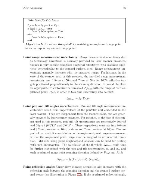
New Approach 36<br />
Data: Scan.(PB,PP ), Δρmax<br />
Δρ ← Scan.PP .ρ − Scan.PB.ρ<br />
if |Δρ| ≤Δρmax then<br />
Scan.PP .IsRecognized ← True<br />
else<br />
Scan.PP .IsRecognized ← False<br />
end<br />
Algorithm 5: Procedure RecognizePo<strong>in</strong>t match<strong>in</strong>g an as-planned range po<strong>in</strong>t<br />
to its correspond<strong>in</strong>g as-built range po<strong>in</strong>t.<br />
Po<strong>in</strong>t range measurement uncerta<strong>in</strong>ty: Range measurement uncerta<strong>in</strong>ty due<br />
to technology limitations is normally provided by laser scanner providers,<br />
though <strong>in</strong> very specific conditions (material reflectivity, with scann<strong>in</strong>g directions<br />
perpendicular to the scanned surface, etc). Range measurement uncerta<strong>in</strong>ty<br />
generally <strong>in</strong>creases with the measured range. For <strong>in</strong>stance, <strong>in</strong> the<br />
case <strong>of</strong> the scanner used <strong>in</strong> this research, the provided range measurement<br />
uncerta<strong>in</strong>ty are: 1.5mm at 50m and 7mm at 50m for 100% reflective targets<br />
positioned perpendicularly to the scann<strong>in</strong>g direction. It would therefore<br />
be appropriate to customize the threshold Δρmax with the range <strong>of</strong> each asplanned<br />
po<strong>in</strong>t, PP .ρ, <strong>in</strong> order to take this uncerta<strong>in</strong>ty <strong>in</strong>to account:<br />
Δρmax = f1 (PP .ρ)<br />
Po<strong>in</strong>t pan and tilt angles uncerta<strong>in</strong>ties: Pan and tilt angle measurement uncerta<strong>in</strong>ties<br />
result from imperfections <strong>of</strong> the pan&tilt unit embedded <strong>in</strong> the<br />
laser scanner. They are <strong>in</strong>dependent from the scanned po<strong>in</strong>t, and are generally<br />
provided by laser scanner providers. For <strong>in</strong>stance, <strong>in</strong> the case <strong>of</strong> the scanner<br />
used <strong>in</strong> this research, pan and tilt uncerta<strong>in</strong>ties are respectively 60μrad<br />
and 70μrad (0 ◦ 0 ′ 12 ′′ and 0 ◦ 0 ′ 14 ′′ ). These respectively translate <strong>in</strong>to 0.6mm<br />
and 0.7mm precision at 10m, or6mm and 7mm precision at 100m. Theimpact<br />
<strong>of</strong> pan and tilt uncerta<strong>in</strong>ties on the as-planned po<strong>in</strong>t range measurement<br />
is that the as-planned po<strong>in</strong>t range may be assigned to an <strong>in</strong>correct direction.<br />
Methods us<strong>in</strong>g po<strong>in</strong>t neighborhood analysis can be used for deal<strong>in</strong>g<br />
with such uncerta<strong>in</strong>ties. The calculation <strong>of</strong> the threshold Δρmax could thus<br />
be further customized with the pan and tilt uncerta<strong>in</strong>ties, uϕ and uθ, and<br />
each as-planned range po<strong>in</strong>t scann<strong>in</strong>g direction def<strong>in</strong>ed by PP .ϕ and PP .θ:<br />
Δρmax = f1 (PP . (ρ, ϕ, θ) , (uϕ,uθ))<br />
Po<strong>in</strong>t reflection angle: Uncerta<strong>in</strong>ty <strong>in</strong> range acquisition also <strong>in</strong>creases with the<br />
reflection angle between the scann<strong>in</strong>g direction and the scanned surface normal<br />
vector (see illustration <strong>in</strong> Figure 3.3). If the as-planned reflection angle,