A Look at the GM 6L80; Part 1 - ATRA
A Look at the GM 6L80; Part 1 - ATRA
A Look at the GM 6L80; Part 1 - ATRA
- TAGS
- part-atra

Create successful ePaper yourself
Turn your PDF publications into a flip-book with our unique Google optimized e-Paper software.
A <strong>Look</strong> <strong>at</strong> <strong>the</strong> <strong>GM</strong> <strong>6L80</strong>; <strong>Part</strong> 1<br />
A <strong>Look</strong> <strong>at</strong> <strong>the</strong><br />
<strong>GM</strong> <strong>6L80</strong>;<br />
<strong>Part</strong> 1<br />
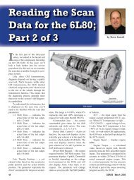
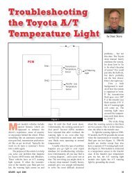
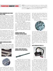
Introduction<br />
The first of ten<br />
new 6-speed autom<strong>at</strong>ics,<br />
<strong>the</strong> <strong>6L80</strong> was introduced<br />
for <strong>the</strong> 2006 model<br />
year (Figure 1). The <strong>6L80</strong><br />
(RPO MYC) is currently<br />
available in <strong>the</strong> Corvette;<br />
Cadillac XLR-V; Cadillac STS-<br />
V; Chevrolet, Cadillac and <strong>GM</strong>C C/K<br />
trucks; and <strong>the</strong> Hummer H2 pl<strong>at</strong>forms.<br />
Fe<strong>at</strong>ures<br />
• Input torque capacity: 430 lb-ft<br />
(583 Nm)<br />
• Output torque capacity: 664 lb-ft<br />
(900 Nm)<br />
• R<strong>at</strong>ios:<br />
1 st — 4.02:1<br />
2 nd — 2.36:1<br />
3 rd — 1.53:1<br />
4 th — 1.15:1<br />
5 th — 0.85:1<br />
6 th — 0.67:1<br />
Figure 1<br />
• M a x i m u m<br />
shift speed: 6500 RPM<br />
• Maximum GVW: 8600 lbs<br />
• Maximum GCVW: 14000 lbs<br />
• PRNDL positions: P, R, N, D, (S or<br />
M)<br />
• 2 shift solenoids (On/Off design):<br />
SS1, SS2<br />
• 6 PWM pressure control solenoids:<br />
PCS1, PCS2, PCS3, PCS4, PCS5,<br />
TCC<br />
Figure 2 Figure 3<br />
Cadillac STS-V<br />
Hydra-M<strong>at</strong>ic<br />
2006 <strong>6L80</strong> (MYC)<br />
Six Speed RWD<br />
Autom<strong>at</strong>ic Transmission<br />
by Steve Garrett<br />
• 32-bit TCM (TEHCM) mounted<br />
inside <strong>the</strong> transmission on <strong>the</strong><br />
valve body (referred to as <strong>the</strong> control<br />
solenoid valve assembly). The<br />
TEHCM incorpor<strong>at</strong>es <strong>the</strong> TCM,<br />
solenoids, pressure switches and<br />
TFT, and is bolted to <strong>the</strong> valve<br />
body.<br />
• EC3 Converter 300mm (Corvette)<br />
258mm twin pl<strong>at</strong>e (XLR-V and<br />
STS-V)<br />
• Fluid required: Dexron VI<br />
• Clutch-to-clutch shifts; 5 clutches,<br />
1 sprag<br />
• Planetary assemblies: Input —<br />
Simpson; Output — Dual Pinion<br />
34 GEARS January/February 2008
Precision m<strong>at</strong>ters.<br />
QUALITY TRANSMISSION SOLENOIDS<br />
FROM THE GLOBAL LEADER IN AUTOMATIC<br />
TRANSMISSION SYSTEMS TECHNOLOGY.<br />
TM<br />
BorgWarner Inc. Transmission Systems<br />
1350 North Greenbriar Drive Unit B Addison, IL 60101 (630) 261-9980<br />
www.borgwarner.com<br />
The BorgWarner Indianapolis 500 Trophy is a registered trademark of BorgWarner Inc.<br />
T<br />
oday's complex electronic transmissions require precise and accur<strong>at</strong>e<br />
control, like <strong>the</strong> control provided by BorgWarner quality transmission<br />
solenoids. Our solenoids are engineered to exacting specific<strong>at</strong>ions,<br />
improving fuel economy and reducing emissions.<br />
Make BorgWarner your one-stop source for autom<strong>at</strong>ic transmission<br />
controls th<strong>at</strong> are competitively priced, readily available and guaranteed<br />
to fit your rebuilds. Call your authorized distributor today and ask<br />
for <strong>the</strong> original parts from <strong>the</strong> leader in autom<strong>at</strong>ic transmission<br />
technology...BorgWarner Inc.
A <strong>Look</strong> <strong>at</strong> <strong>the</strong> <strong>GM</strong> <strong>6L80</strong>; <strong>Part</strong> 1<br />
• Vane-style oil pump<br />
• Internally-mounted input and output shaft, and Hall<br />
Effect speed sensors<br />
• Internal Mode Switch (IMS)<br />
• Performance Algorithm Shifting (PAS) programming<br />
• Performance Algorithm Lift foot (PAL) programming<br />
• Sport mode and TAP shift<br />
• Adaptive str<strong>at</strong>egies with fast learn capabilities<br />
• Up to 75 transmission-only DTCs<br />
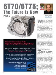
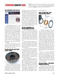
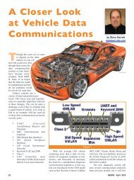
Checking Fluid Level<br />
The <strong>6L80</strong> transmission requires an unusual process<br />
for checking its fluid level. Many <strong>6L80</strong> applic<strong>at</strong>ions don’t<br />
have a dipstick; <strong>the</strong>re’s a plug in <strong>the</strong> dipstick hole. The<br />
plug can be removed and <strong>the</strong> hole used as a fill point for<br />
transmission fluid (Figure 2). Here’s how to check <strong>the</strong><br />
fluid level:<br />
Bring <strong>the</strong> transmission fluid temper<strong>at</strong>ure between 86º–<br />
122ºF (30º–50ºC). You can verify this using a scan tool, <strong>the</strong><br />
driver inform<strong>at</strong>ion center, or <strong>the</strong> transmission gauge.<br />
If <strong>the</strong> transmission has a dipstick, use th<strong>at</strong> to check <strong>the</strong><br />
fluid level; on applic<strong>at</strong>ions without a dipstick:<br />
• Park <strong>the</strong> vehicle on level ground.<br />
• Start <strong>the</strong> engine and let it idle.<br />
• Shift <strong>the</strong> transmission through each range, pausing in each<br />
range for about 3 seconds to give <strong>the</strong> clutches a chance to<br />
fill.<br />
• Place <strong>the</strong> transmission in park.<br />
• Remove <strong>the</strong> level control plug loc<strong>at</strong>ed in <strong>the</strong> transmission<br />
Figure 6<br />
Figure 4<br />
Figure 5<br />
oil pan. The fluid should drip out <strong>the</strong> level control<br />
hole. If so, <strong>the</strong> fluid level is okay.<br />
Ø If fluid doesn’t drip from <strong>the</strong> level control hole,<br />
add Dexron VI until fluid starts to drip from <strong>the</strong><br />
hole.<br />
Ø If fluid runs from <strong>the</strong> hole, wait until <strong>the</strong> fluid<br />
stops running out to lower <strong>the</strong> fluid to <strong>the</strong><br />
proper level.<br />
The level is correct when fluid drips from <strong>the</strong> hole.<br />
If a steady stream is present or no flow is present <strong>the</strong><br />
36 GEARS January/February 2008
������������������������<br />
�����������������������������������������������������������������������������������������������������������������<br />
������������������������������������������������������������������������������������������������<br />
������������������������������������������������������������������������������������������������������������<br />
��������������������������������������������������������������������������������������������������������������<br />
����������������������������������������������������<br />
��������������������������������������������������������������������������������������������������������������<br />
����������������������������������������<br />
��������������<br />
������������� ����������<br />
�������������������������������� ��� ���<br />
���������������� �������������� ������������������<br />
����������<br />
��������������������������������<br />
��������������<br />
�����������������������������<br />
��������������������<br />
������������ �������������������������� ��������������������������<br />
�������������������<br />
�������������������������<br />
������������<br />
������������������<br />
����������������� ������ ������<br />
����������������� ��� ��<br />
��������������� ���������� ����������<br />
���������������������������������������������������������������������������������������������������������<br />
����������������������������������������<br />
GoldStripe is a registered trademark of SPX Filtran, Raybestos and Allom<strong>at</strong>ic are registered trademarks of Raybestos Powertrain Corpor<strong>at</strong>ion.
A <strong>Look</strong> <strong>at</strong> <strong>the</strong> <strong>GM</strong> <strong>6L80</strong>; <strong>Part</strong> 1<br />
fluid level is incorrect. Readjust <strong>the</strong><br />
fluid level, and reinstall <strong>the</strong> fill plug<br />
and <strong>the</strong> level control plug.<br />
You can add fluid through <strong>the</strong> dipstick<br />
hole or through <strong>the</strong> level control<br />
hole.<br />
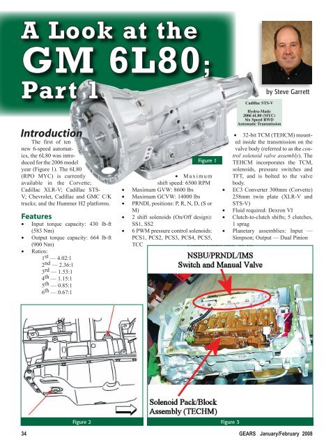
Wh<strong>at</strong>’s Inside?<br />
NSBU/PRNDL/IMS Switch<br />
(Figure 3)— The internal mode switch<br />
(IMS) is mounted to <strong>the</strong> valve body<br />
and is connected mechanically to <strong>the</strong><br />
manual valve. Electrically <strong>the</strong> internal<br />
mode switch oper<strong>at</strong>es much like o<strong>the</strong>r<br />
<strong>GM</strong> applic<strong>at</strong>ions:<br />
The TCM sends an 8.3–9.3 volt<br />
bias to <strong>the</strong> internal mode switch on 4<br />
circuits: A, B, C and P. Pin N, which<br />
is used for neutral starting oper<strong>at</strong>ions,<br />
is fed system voltage from <strong>the</strong> ECM.<br />
As you move <strong>the</strong> range selector, <strong>the</strong><br />
internal mode switch will ground or<br />
open <strong>the</strong> circuits or circuit required to<br />
indic<strong>at</strong>e <strong>the</strong> specific manual valve position.<br />
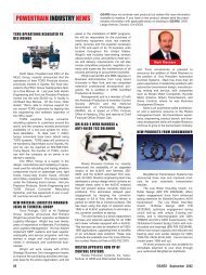
The TCM identifies <strong>the</strong> range by<br />
<strong>the</strong> voltage sequence from <strong>the</strong> switch<br />
(Figure 4).<br />
Low = Grounded (0 Volts)<br />
High = Open (Source Voltage)<br />
Note: Not all applic<strong>at</strong>ions will<br />
include all <strong>the</strong> ranges shown in <strong>the</strong><br />
chart<br />
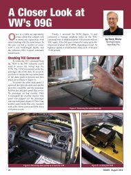
Input and Output Speed Sensors<br />
— The speed sensors are Hall Effect<br />
assemblies and are mounted to <strong>the</strong><br />
control valve assembly (valve body).<br />
The TCM provides a signal voltage of<br />
8.3–9.3 volts for <strong>the</strong> sensor oper<strong>at</strong>ion.<br />
As <strong>the</strong> clutch housings rot<strong>at</strong>e, <strong>the</strong> sensors<br />
produce a square wave signal th<strong>at</strong><br />
varies frequency with <strong>the</strong> speed of <strong>the</strong><br />
clutch housing (Figure 5). The TCM<br />
will monitor <strong>the</strong> frequency of <strong>the</strong> signal<br />
to determine <strong>the</strong> input or output speed<br />
(Figure 6 & 7).<br />
Control Solenoid Body and TCM<br />
Assembly (TEHCM)<br />
— The control solenoid<br />
valve assembly consists<br />
of <strong>the</strong>se components:<br />
• 2 shift solenoids<br />
(On/Off design):<br />
SS1, SS2; 16-20<br />
ohms <strong>at</strong> 70ºF (21ºC)<br />
Figure 7<br />
• 6 controlled pressure control solenoids;<br />
PCS, PCS2, PCS3, PCS4,<br />
PCS5 and TCC; 3.0-5.5 ohms <strong>at</strong><br />
70ºF (21ºC), 0.9-amp current limit,<br />
solenoid oper<strong>at</strong>ional voltage from<br />
TCM 8.3–9.3 volts, cleaning pulse<br />
every 30 seconds during P/N.<br />
• 32-bit TCM (TEHCM); mounted<br />
inside <strong>the</strong> transmission on <strong>the</strong><br />
valve body. Thermal protected<br />
290ºF (144ºC), default 3 rd or 5 th .<br />
• 4 pressure switches th<strong>at</strong> monitor<br />
valve and clutch hydraulic oper<strong>at</strong>ion<br />
and clutch volume index (CVI<br />
— adaptive learn)<br />
• A transmission fluid temper<strong>at</strong>ure<br />
sensor (TFT) NTC <strong>the</strong>rmistor.<br />
• 2 TCM internal temper<strong>at</strong>ure sensors<br />
Figure 8<br />
38 GEARS January/February 2008
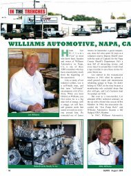
SuperFlow 2008 Buyers Guide for<br />
Quality Transmission Rebuilding Equipment<br />
SuperFlow TransDyno SF-66K<br />
New modular transmission dynamometer.<br />
Offers <strong>the</strong> convenience, reliability, vers<strong>at</strong>ility and ability to test virtually every<br />
transmission on <strong>the</strong> road, including <strong>the</strong> new Allison models. Handles hydraulically<br />
and electrically shifted transmissions, foreign and domestic, in FWD, RWD<br />
and AWD configur<strong>at</strong>ions. Monitors and tests virtually every aspect of transmission<br />
performance, under simul<strong>at</strong>ed road load conditions, before <strong>the</strong> transmission<br />
is installed … supported by <strong>the</strong> accuracy and superior document<strong>at</strong>ion of <strong>the</strong><br />
exclusive TDAC (Transmission D<strong>at</strong>a Acquisition & Control) System.<br />
AXILINe Solenoid Testers,<br />
a must for testing <strong>the</strong> weakest<br />
link, six <strong>at</strong> a time. Easy to use.<br />
AXILINe unit Testers<br />
Simple. Compact. Portable.<br />
Saves valuable time by reducing<br />
unnecessary transmission<br />
install<strong>at</strong>ions and removals.<br />
AXILINe electronic Shifter<br />
This stand-alone or addon<br />
unit shifts electronic<br />
transmissions can control<br />
up to 16 solenoids <strong>at</strong> a time,<br />
including models incorpor<strong>at</strong>ing<br />
l<strong>at</strong>est multiple pulsewidth<br />
modul<strong>at</strong>ed systems.<br />
TCRS Torque Converter<br />
Testing and Rebuilding Systems<br />
Excellent profit center for transmission repair shops or stand-alone<br />
startups … and smartest way to save time and prevent costly comebacks.<br />
TCRS Single Gun<br />
Auto Weld Aligner<br />
Standard of <strong>the</strong> industry.<br />
P<strong>at</strong>ented auto-tack and autoweld.<br />
Do “bowl buildups” and<br />
weld on impeller hubs.<br />
TAC 12+ control panel lets<br />
you autom<strong>at</strong>ically control number<br />
of tacs and dur<strong>at</strong>ion.<br />
u<br />
really need<br />
w…<br />
New! Improved!<br />
TCRS Torque<br />
Converter balancer<br />
now with autom<strong>at</strong>ic<br />
weight indexing,<br />
runout compens<strong>at</strong>ion<br />
mode, push<br />
buttom polishing<br />
and better accuracy<br />
and repe<strong>at</strong>ability<br />
than ever before<br />
SuperShifter<br />
The NEW Durable In-Car Tester<br />
Rugged design, solid st<strong>at</strong>e electronics, impact-resistant<br />
housing. Tests most l<strong>at</strong>e model transmissions. Controls<br />
<strong>the</strong> transmission from inside <strong>the</strong> car. Tests Solenoid<br />
current/resistance. Oper<strong>at</strong>or ID and D<strong>at</strong>e/Time stamp.<br />
External device connectivity.<br />
AXILINe<br />
Transmission Dynamometers<br />
AXILINe Valve body Testers<br />
Test valve bodies, solenoids<br />
and pressure transducers<br />
with actual transmission<br />
pressures and he<strong>at</strong>ed oil<br />
under toughest simul<strong>at</strong>ed<br />
driving conditions.<br />
Test converters BEFORE<br />
you ship or install with<br />
TCRS Hub RuNOuT<br />
INSpeCTION uNITS.<br />
Ensure your converter<br />
quality (after welding) with<br />
TCRS AIR TeST STANDS<br />
for diagnosing leaks.<br />
www.superflow.com ���� ����� ������� ��� ������ �� ����� � ��� ����� �������� �� ����� ��������
A <strong>Look</strong> <strong>at</strong> <strong>the</strong> <strong>GM</strong> <strong>6L80</strong>; <strong>Part</strong> 1<br />
Pressure Switches — The pressure<br />
switches are housed as part of<br />
<strong>the</strong> control solenoid valve assembly. 4<br />
switches are used: 1, 3, 4 and 5. The<br />
switches provide an input to <strong>the</strong> TCM<br />
and have two basic functions:<br />
• To monitor clutch regul<strong>at</strong>or valve<br />
and clutch hydraulic oper<strong>at</strong>ion<br />
(Figure 8).<br />
• To monitor clutch volume index<br />
(CVI — adaptive learning).<br />
Solenoid Oper<strong>at</strong>ion<br />
IMPORTANT: In systems using<br />
<strong>the</strong> Bosch solenoid system, ON/OFF<br />
refers to <strong>the</strong> solenoids’ hydraulic commanded<br />
position, not <strong>the</strong>ir electrical<br />
command as with o<strong>the</strong>r applic<strong>at</strong>ions;<br />
more on this l<strong>at</strong>er.<br />
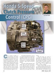
Shift solenoid and PCS oper<strong>at</strong>ion<br />
is controlled by <strong>the</strong> TEHCM (TCM).<br />
The TCM regul<strong>at</strong>es <strong>the</strong> feed voltage<br />
to <strong>the</strong> solenoids between 8.3–9.3 volts<br />
(Figure 9). The TCM <strong>the</strong>n regul<strong>at</strong>es<br />
<strong>the</strong> current flow through <strong>the</strong> solenoids.<br />
The shift solenoids are On/Off design<br />
with <strong>the</strong> TCM controlling <strong>the</strong> power<br />
and ground for <strong>the</strong> solenoids (Figure<br />
10). The pressure control solenoids are<br />
high-side, PWM controlled. The TCM<br />
is overcurrent and overtemper<strong>at</strong>ure protected<br />
(Figure 11, 12, &13).<br />
Bosch refers to <strong>the</strong> solenoids by<br />
<strong>the</strong>ir hydraulic oper<strong>at</strong>ion: Normally<br />
High (NH) or Normally Low (NL).<br />
Normally High means <strong>the</strong> solenoid<br />
allows pressure to travel to <strong>the</strong> clutch<br />
when <strong>the</strong> solenoid is off. Normally<br />
Low means <strong>the</strong> solenoid prevents pressure<br />
from getting to a clutch when <strong>the</strong><br />
solenoid is off.<br />
IMPORTANT: This concept of<br />
Normally High and Normally Low to<br />
describe solenoid oper<strong>at</strong>ion is far more<br />
involved — and confusing — than it<br />
might initially appear. We’ll discuss<br />
<strong>the</strong> oper<strong>at</strong>ion of <strong>the</strong> Bosch solenoids in<br />
detail in an upcoming issue of GEARS.<br />
The solenoids are protected by <strong>the</strong><br />
filter pl<strong>at</strong>e. The filter pl<strong>at</strong>e is housed<br />
between <strong>the</strong> valve body and <strong>the</strong> control<br />
solenoid valve assembly (TEHCM)<br />
and must be replaced any time <strong>the</strong><br />
valve body or control solenoid valve<br />
assembly (TEHCM) is replaced, or are<br />
unbolted from each o<strong>the</strong>r.<br />
Clutches<br />
The <strong>6L80</strong> transmission (Figure 14)<br />
uses three rot<strong>at</strong>ing clutches and two<br />
st<strong>at</strong>ionary clutches.<br />
1-2-3-4/Forward Clutch — This<br />
clutch is applied in 1 st through 4 th<br />
gears. The 1-2-3-4/forward clutch is<br />
loc<strong>at</strong>ed in <strong>the</strong> bottom of <strong>the</strong> reverse<br />
clutch housing. When applied, it locks<br />
<strong>the</strong> reverse drum to <strong>the</strong> 2-6 and 3-5reverse<br />
shell to drive <strong>the</strong> lower sun gear<br />
for <strong>the</strong> output carrier.<br />
2-6 Clutch — This is one of <strong>the</strong><br />
st<strong>at</strong>ionary clutches. It’s loc<strong>at</strong>ed on top<br />
of <strong>the</strong> center support assembly. It prevents<br />
<strong>the</strong> 2-6 and 3-5-reverse shell from<br />
rot<strong>at</strong>ing.<br />
3-5-Reverse Clutch — This clutch<br />
is used in 3 rd , 5 th and reverse. It’s<br />
loc<strong>at</strong>ed in <strong>the</strong> reverse clutch housing.<br />
When applied, it connects <strong>the</strong> reverse<br />
drum to <strong>the</strong> 2-6 and 3-5-reverse shell.<br />
The clutch <strong>the</strong>n drives <strong>the</strong> front output<br />
sun gear in <strong>the</strong> output carrier.<br />
4-5-6/Input Clutch — This clutch<br />
is loc<strong>at</strong>ed in <strong>the</strong> input housing. When<br />
applied, it locks <strong>the</strong> input housing to <strong>the</strong><br />
4-5-6 drive hub, which drives <strong>the</strong> lower<br />
output carrier.<br />
Low/Reverse Clutch — This sta-<br />
Figure 9<br />
Figure 10<br />
Figure 11<br />
tionary clutch is loc<strong>at</strong>ed in <strong>the</strong> lower<br />
section of <strong>the</strong> center support. The Low/<br />
Reverse clutch is used in reverse and<br />
manual low.<br />
40 GEARS January/February 2008
A <strong>Look</strong> <strong>at</strong> <strong>the</strong> <strong>GM</strong> <strong>6L80</strong>; <strong>Part</strong> 1<br />
Powerflow<br />
First Gear: 1-2-3-4/Forward<br />
clutch (rot<strong>at</strong>ing clutch) is applied.<br />
Engine torque is applied to <strong>the</strong><br />
input shaft, which is <strong>the</strong> driving component<br />
for all ranges. When <strong>the</strong> input<br />
shaft rot<strong>at</strong>es, it drives <strong>the</strong> input ring<br />
gear. The clutch drives <strong>the</strong> pinions of<br />
<strong>the</strong> input carrier, which is splined to <strong>the</strong><br />
reverse drum.<br />
When <strong>the</strong> 1-2-3-4/Forward clutch<br />
applies, it transfers engine torque<br />
through <strong>the</strong> input shaft to <strong>the</strong> reverse<br />
drum. The torque <strong>the</strong>n transfers to <strong>the</strong><br />
1-2-3-4/input shell. The input shell is<br />
splined to <strong>the</strong> lower output sun gear.<br />
The sun gear drives <strong>the</strong> output carrier<br />
pinions, rot<strong>at</strong>ing <strong>the</strong> output ring gear <strong>at</strong><br />
a 4.027:1 gear r<strong>at</strong>io.<br />
Second Gear: 1-2-3-4/Forward<br />
clutch (rot<strong>at</strong>ing clutch) and 2-6 (st<strong>at</strong>ionary)<br />
are applied.<br />
With <strong>the</strong> 2-6 clutch applied, <strong>the</strong><br />
2-6 and 3-5-reverse shell can’t rot<strong>at</strong>e.<br />
With <strong>the</strong> shell locked to <strong>the</strong> case, <strong>the</strong><br />
upper output sun gear is held. Engine<br />
torque is still being applied through <strong>the</strong><br />
1-2-3-4/Forward clutch, which drives<br />
<strong>the</strong> lower sun gear. The combin<strong>at</strong>ion<br />
of <strong>the</strong> two gearsets provides a 2.364:1<br />
gear r<strong>at</strong>io.<br />
Third Gear: 1-2-3-4/Forward<br />
clutch (rot<strong>at</strong>ing clutch) and 3-5-Reverse<br />
clutches (rot<strong>at</strong>ing clutch) are applied.<br />
With <strong>the</strong> 3-5-Reverse clutch applied,<br />
<strong>the</strong> reverse drum is locked to <strong>the</strong> 2-6<br />
and 3-5-Reverse shell. Engine torque is<br />
now transferred through both sun shells,<br />
driving <strong>the</strong> output sun gears and output<br />
carrier. The pinions rot<strong>at</strong>e, turning <strong>the</strong><br />
output ring gear <strong>at</strong> a 1.532:1 r<strong>at</strong>io.<br />
4 th Gear: 1-2-3-4/Forward clutch<br />
(rot<strong>at</strong>ing clutch) and 4-5-6/Input clutches<br />
(rot<strong>at</strong>ing clutch) are applied.<br />
With <strong>the</strong> 4-5-6/Input clutch applied,<br />
<strong>the</strong> hub is driven <strong>at</strong> engine speed. The<br />
1-2-3-4/Forward clutch is still applied,<br />
rot<strong>at</strong>ing <strong>the</strong> lower output sun gear,<br />
which rot<strong>at</strong>es <strong>the</strong> ring gear <strong>at</strong> a 1.152:1<br />
r<strong>at</strong>io.<br />
5 th Gear: 4-5-6/Input (rot<strong>at</strong>ing<br />
clutch) and 3-5-Reverse clutches (rot<strong>at</strong>ing<br />
clutch) are applied.<br />
The 1-2-3-4/Forward clutch releases.<br />
The 3-5-Reverse clutch is now<br />
applied, driving <strong>the</strong> upper sun gear in<br />
<strong>the</strong> output gearset. At <strong>the</strong> same time,<br />
engine torque travels through <strong>the</strong> 4-5-<br />
6/Input hub, driving <strong>the</strong> carrier, which<br />
cre<strong>at</strong>es an overdrive r<strong>at</strong>io of 0.852:1.<br />
6 th Gear: 4-5-6/Input (rot<strong>at</strong>ing<br />
clutch) and 2-6 clutches (st<strong>at</strong>ionary)<br />
are applied.<br />
With only <strong>the</strong> 4-5-6/input clutch<br />
applied, all of <strong>the</strong> engine torque travels<br />
through <strong>the</strong> output carrier with an overdrive<br />
r<strong>at</strong>io of 0.667:1.<br />
Reverse: 3-5-Reverse (rot<strong>at</strong>ing<br />
clutch) and Low/Reverse clutches (st<strong>at</strong>ionary)<br />
are applied.<br />
With <strong>the</strong> 3-5-Reverse clutch<br />
applied, engine torque from <strong>the</strong> input<br />
shaft is sent through <strong>the</strong> input gear<br />
set, through <strong>the</strong> reverse drum, to <strong>the</strong><br />
2-6 and 3-5-Reverse sun shell. The<br />
upper sun gear rot<strong>at</strong>es <strong>the</strong> pinions.<br />
The carrier <strong>at</strong>tempts to rot<strong>at</strong>e, but <strong>the</strong><br />
Low/Reverse clutch is also applied,<br />
holding <strong>the</strong> carrier st<strong>at</strong>ionary. This<br />
causes <strong>the</strong> ring gear to rot<strong>at</strong>e backward<br />
<strong>at</strong> a 3.064:1 r<strong>at</strong>io.<br />
Figure 13<br />
Figure 14<br />
Th<strong>at</strong>’s enough for this issue; in<br />
<strong>the</strong> next issue of GEARS, we’ll look <strong>at</strong><br />
some of <strong>the</strong> diagnostic processes for<br />
<strong>the</strong>se units.<br />
Figure 12<br />
42 GEARS January/February 2008
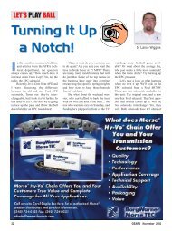
<strong>GM</strong> parts enGines<br />
We’ve thouGht of everythinG.<br />
������������������������������������������<br />
������������������������ *<br />
���������������������������� **��<br />
$100 MaiL-in reb<strong>at</strong>e †<br />
����������������������<br />
��������������<br />
����������������������������������<br />
�����������������������<br />
��������������������������������������������<br />
��������������������������������<br />
�����������������������������������������<br />
���������������������������������������<br />
������������������������������������������������<br />
������������������������������������������<br />
������������������������������������������������<br />
���������������������������������<br />
������������������������������������������������<br />
��������������������������������������������������������������������������������������������<br />
���������������������������������������������������������������������������������������������<br />
�����������������������������������������������������������������������������������������<br />
��������������������������������������������������������������������������������������������<br />
�������������������������������������������������������������������������������������������<br />
���������������������������������������������������������������<br />
Want Genuine enGines?<br />
CaLL <strong>the</strong> <strong>GM</strong> parts<br />
poWertrain ContaCt Center<br />
<strong>at</strong> 1.866.453.4123 today.<br />
����������������������������������������������������������������������������������������������������������<br />
����������������������������������������������������������������������������������������������������<br />
�������������������������������������������������������������������������������������������������<br />
����������������������������������<br />
������������������������������������<br />
� �����������������������������������