TensiNews 18 - April 2010 - TensiNet
TensiNews 18 - April 2010 - TensiNet
TensiNews 18 - April 2010 - TensiNet

You also want an ePaper? Increase the reach of your titles
YUMPU automatically turns print PDFs into web optimized ePapers that Google loves.
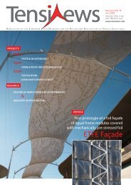
N EWSLETTER OF THE E UROPEAN BASED N ETWORK FOR THE D ESIGN AND R EALISATION OF T ENSILE S TRUCTURES<br />
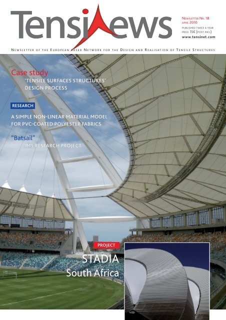
Case study<br />
‘TENSILE SURFACES STRUCTURES’<br />
DESIGN PROCESS<br />
RESEARCH<br />
A SIMPLE NON-LINEAR MATERIAL MODEL<br />
FOR PVC-COATED POLYESTER FABRICS<br />
“Batsail”<br />
IMS RESEARCH PROJECT<br />
PROJECT<br />
STADIA<br />
South Africa<br />
NEWSLETTER NR. <strong>18</strong><br />
APRIL <strong>2010</strong><br />
PUBLISHED TWICE A YEAR<br />
PRICE 15€ (POST INCL)<br />
www.tensinet.com
form TL<br />
partners<br />
2009<br />
Buro Happold<br />
www.burohappold.com<br />
Canobbio S.p.A.<br />
www.canobbio.com<br />
Ceno Tec<br />
www.ceno-tec.de<br />
Dyneon<br />
www.dyneon.com<br />
FabricArt<br />
Membrane Structures<br />
www.fabricart.com.tr/<br />
Ferrari sa<br />
www.ferrari-textiles.com<br />
Form TL<br />
www.Form-tl.de<br />
Hightex GmbH<br />
www.hightexworld.com<br />
Mehler Texnologies<br />
www.mehlertexnologies.com<br />
Messe Frankfurt<br />
Techtextil<br />
www.techtextil.de<br />
Saint-Gobain<br />
www.sheerfill.com<br />
Sioen Industries<br />
www.sioen.com<br />
Taiyo Europe<br />
www.taiyo-europe.com<br />
technet GmbH<br />
www.technet-gmbh.com<br />
Verseidag<br />
www.vsindutex.de<br />
INFO<br />
Editorial Board<br />
John Chilton, Evi Corne,<br />
Peter Gosling, Marijke Mollaert,<br />
Javier Tejera<br />
Coordination<br />
Marijke Mollaert,<br />
phone: +32 2 629 28 45,<br />
marijke.mollaert@vub.ac.be<br />
Address<br />
Vrije Uni ver siteit Brussel (VUB),<br />
Dept. of Architectural Engineering,<br />
Pleinlaan 2, 1050 Brus sels, Belgium<br />
fax: +32 2 629 28 41<br />
ISSN<br />
1784-5688<br />
All copyrights remain by each<br />
author<br />
Price 15€<br />
postage & packing included<br />
2 TENSINEWS NR. <strong>18</strong> – APRIL <strong>2010</strong><br />
PROJECTS<br />
RESEARCH<br />
ARTICLE<br />
MISC<br />
contents<br />
PAGE<br />
4 & 5 Pakistan<br />
TOLL PLAZA CANOPIES<br />
Spain LA FACTORIA<br />
Sun shading of the streets of the shopping mall<br />
PAGE<br />
23 VIENNA UNIVERSITY OF TECHNOLOGY MASTER PROGRAM<br />
MEMBRANE LIGHTWEIGHT STRUCTURES<br />
ANHALT UNIVERSITY OF APPLIED SCIENCES<br />
MASTER COURSE MEMBRANE STRUCTURES<br />
LITERATURE SPANISH EDITION<br />
European Design Guide for Tensile Surface Structures<br />
n°<strong>18</strong><br />
Turkey WEDDING HOUSE CANOPY<br />
A New Interpretation for the Wedding Gown<br />
Turkey SPORT FACILITIES<br />
8 > 13 South Africa 4 STADIUM PROJECTS<br />
Johannesburg Soccer City Stadium<br />
Durban Moses Mabhida Stadium<br />
Port Elizabeth Stadium of the “windy city”<br />
Cape Town The new Cape Town Stadium<br />
16 & 17 USA LONE BUTTE CASINO Lights Up the Desert Sky<br />
Spain ETFE SINGLE SKIN<br />
Aranda de Duero ROOF<br />
22 The Netherlands<br />
JINSO PAVILION Extension to a catering pavilion<br />
PAGE<br />
6 & 7 A SIMPLE NON-LINEAR MATERIAL MODEL<br />
for PVC-coated polyester fabrics<br />
14 & 15 “BATSAIL” IMS Research Project<br />
15 FORMFINDER SOFTWARE<br />
"One Click" Cost Estimation for the architectural design<br />
of membrane structures<br />
<strong>18</strong> CASE STUDY ‘Tensile surfaces structures’ design process<br />
THE TS ARCHI PROFILE PROFIL TENSION SYSTEM INNOVATION<br />
24 SYMPOSIUM TENSILE ARCHITECTURE: Connecting Past & Future
E dito<br />
Symposium <strong>2010</strong><br />
16-<strong>18</strong> th September <strong>2010</strong><br />
UACG, Sofia, Bulgaria<br />
Every third year Tensinet organizes a Symposium. The field of Tensile Surface Structures is evolving: new materials and new realizations prove<br />
that the field of applications is steadily growing. The last two Symposia took place in Brussels (VUB) and in Milan (Politecnico di Milano) with<br />
increasing numbers of participants and speakers. These Symposia provide an opportunity for information transfer on the state of the art and<br />
new technologies, enabling delegates to share knowledge with a wider audience. On the other hand they advertise tensile surface structures and<br />
make them better known to potential clients as well as other professionals in the building industry.<br />
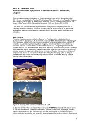
As members of the Scientific Committee, Marijke Mollaert and myself, together with Evi Corne, have visited the UACG in Sofia. We had a warm<br />
welcome from the Principal and the Faculty who had given us the opportunity to visit the university facilities in preparation for the Symposium.<br />
The Organizing Committee in Bulgaria has already prepared the website for registration. You can access all necessary information about our<br />
Symposium on the 16th-<strong>18</strong>th September at http://tensinet<strong>2010</strong>.uacg.bg.<br />
The theme of the symposium “Tensile Architecture: connecting past and future” is well suited for the market situation in Bulgaria, since several<br />
archaeological sites could benefit from translucent, lightweight temporary covers. The Symposium will feature a number of stimulating<br />
(keynote) lectures by prominent experts such as Martin Glass (gmp architecten, DE), Françoise Fournier (FERRARI SA, FR), Jan Laperre<br />
(Centexbel, BE), Peter Gosling (Newcastle University, UK), Bernd Stimpfle and Gerd Schmid (form TL, DE), Markus Balz (schlaich bergermann<br />
und partner, DE) and many others.<br />
A number of <strong>TensiNet</strong> meetings will also take place during the Symposium.<br />
We invite you to attend our Symposium and ask you to inform colleagues about this event.<br />
Currently <strong>TensiNet</strong> has more than 200 members from over 40 countries and 15 partners. We are happy to welcome a new partner within <strong>TensiNet</strong>:<br />
the German engineering and manufacturing company with a long history in the field of tensile fabric architecture: Hightex GmbH, Rimsting.<br />
I hope you enjoy this current issue of <strong>TensiNews</strong> and I’m looking forward to seeing you in Sofia in September,<br />
Forthcoming Meetings<br />
<strong>TensiNet</strong> Meetings<br />
Verseidag, Krefeld, Germany<br />
20/04/<strong>2010</strong><br />
Partner meeting 1 � 11:00 - 12:30<br />
Working Group ETFE � 13:30 - 15:30<br />
Working Group Analysis & Materials � 13:30 - 15:30<br />
Location: VERSEIDAG-INDUTEX GmbH<br />
Industriestraße 56 - D-47803 Krefeld<br />
<strong>TensiNet</strong> Meetings, UACEG, Bulgaria<br />
<strong>TensiNet</strong> Symposium <strong>2010</strong><br />
15/09/<strong>2010</strong><br />
Partner Meeting 2<br />
Annual General Meeting<br />
Working Group ETFE<br />
Working Group Analysis & Materials<br />
Working Group Standardisation & Eurocode<br />
Forthcoming Events<br />
International exhibition ROOF INDIA <strong>2010</strong> Chennai Trade Centre, Chennai,<br />
India 23-25/04/<strong>2010</strong> www.roofindia.com ● Workshop Textile Roofs<br />
<strong>2010</strong> TUB, Berlin, Germany 03-05/06/<strong>2010</strong> www.textile-roofs.com ●<br />
1 st International Conference on Structures and Architecture (ICSA <strong>2010</strong>)<br />
University of Minho, Guimarães, Portugal 21- 23/07/<strong>2010</strong> www.icsa<strong>2010</strong>.com<br />
● Symposium <strong>2010</strong> Tensile Architecture: Connection Past and<br />
Future University of Architecture, Civil Engineering and Geodesy<br />
16 - <strong>18</strong>/09/<strong>2010</strong> http://tensinet<strong>2010</strong>.uacg.bg / ● International Symposium<br />
on Spatial structures - Temporary and Permanent IASS <strong>2010</strong><br />
Shanghai, China 08-12/11/<strong>2010</strong> www.iass<strong>2010</strong>.cn ● International trade Fair<br />
&Symposium Techtextil 2011 Frankfurt, Germany 24 –26/05/2011<br />
http://techtextil.messefrankfurt.com ● International conference on<br />
Structural Membranes 2011 Barcelona, Spain 05 –07/10/2011<br />
http://congress.cimne.com/membranes2011/frontal/Dates.asp<br />
©JÜRGEN LÖSEL<br />
TENSINEWS NR. <strong>18</strong> – APRIL <strong>2010</strong> 3
4 TENSINEWS NR. <strong>18</strong> – APRIL <strong>2010</strong><br />
MEHLER TEXNOLOGIES<br />
Tollink Pakistan, a subsidiary of Tollink South Africa, needed BOT-Toll<br />
(Build, Operate and Transfer) collection facilities in Islamabad and chose<br />
for their project a canopy that stood out different in its form and<br />
architectural apparition. The preliminary design from Isbah Hassan<br />
& Associates was much appreciated. The structural engineering was done<br />
by Amjad Niazi Associates whereas the membrane engineering was done<br />
in China by Covertex. Mehatop FR 1000 was used as membrane: a PVC<br />
coated polyester fabric with a PVDF top coating on both sides.<br />
It has a weight of 1050g/m² and a tensile strength of 120KN/m –<br />
110KN/m in warp and weft direction.<br />
The most challenging part of the project was giving the required shape to<br />
the 200mm diameter pipe, with 6mm wall thickness.<br />
For this project a pipe bending machine and the allied heat process had to<br />
be made. Once the pipes were bent they were welded on the ground and<br />
the whole frame was lifted up to be placed on the vertical structural<br />
elements. The very first project of tensile fabric structure in Pakistan got<br />
instant attention of the architects and was much appreciated.<br />
� Kashif Ahmed,South Asia, Mehler Texnologies GmbH<br />
� www.mehler-texnologies.com<br />
Toll<br />
Plaza<br />
canopies<br />
at Rawat & I.J. Principal Road<br />
Islamabad, Pakistan<br />
Name of the project: Toll Plaza Canopies<br />
Location address: Rawat & I.J. Principal Road, Islamabad, Pakistan<br />
Client (investor): Tollink Pakistan<br />
Function of building: Toll collection facility<br />
Type of application of the membrane: Canopy Cover<br />
Year of construction: 2009<br />
Architects: Isbah Hassan & Associates<br />
Multi disciplinary engineering, Main contractor, manufacture and installation: Ramcon<br />
Structural engineers: Amjad Niazi & Associates<br />
Consulting engineer for the membrane: Jason Wang, Covertex China<br />
Tensile membrane contractor: Covertex China<br />
Supplier of the membrane material: Mehler Texnologies Germany<br />
Material: PVDF, Mehatop FR1000 Type III<br />
Covered surface: 700m²<br />
The first open-air commercial<br />
centre La Factoria is situated in<br />
the region of Huelva, Spain.<br />
During spring and summer<br />
MEHLER TEXNOLOGIES<br />
Sun shading of the streets<br />
of the shopping mall<br />
temperatures exceed 40°C and<br />
solar radiation hits directly and<br />
very intensively. The demand was<br />
to find and realize a possibility of<br />
ARCH-ART<br />
Wedding House<br />
Canopy<br />
The Municipality of Karşıyaka<br />
needed an extension for the<br />
main wedding house. The<br />
ARCH-ART team designed a<br />
conical roof with a hexagonal<br />
plan, supported by six arch<br />
structures which as a whole<br />
represent a wedding gown.<br />
The after wedding cocktail<br />
receptions and the Turkish<br />
traditional jewelry ceremonies<br />
take place at this extended area.<br />
The main function of the roof is<br />
to protect the guests from rain<br />
surprises but mostly from<br />
Izmir’s hot sun. Also, by creating<br />
an optical highlight that can be<br />
seen from a large distance,<br />
especially from the ferries that<br />
constantly carry passengers<br />
between the two main zones of<br />
the bay; the roof creates an<br />
attraction point, enhancing the<br />
wedding house. The roof stands<br />
like a white flower blooming,<br />
representing the purity of the
La Factoria<br />
protecting the 8 streets of the<br />
commercial centre from the sun<br />
and give shadow to its visitors<br />
during their stay.<br />
On demand Carpatec designed,<br />
produced and installed a total of<br />
64 hyperbolic paraboloids of<br />
9.80m x 4.80m between the<br />
buildings of the centre and with a<br />
height of 9m, thus protecting the<br />
8 streets and the façades of more<br />
than 200 shops. For the design<br />
the software programme Rhino<br />
Membrane was used, for the<br />
calculation of loads and form<br />
finding Forten 3000 was applied.<br />
Tensioning ropes and fittings are<br />
of stainless steel 316. The<br />
membrane is Mehler Valmex FR<br />
700 MEHATOP F – Type I. The<br />
welding was made at high<br />
frequency. Production and<br />
installation were made within<br />
only 21 days from receipt of<br />
order, thus assuring that the<br />
project was ready on the<br />
inauguration day of the centre in<br />
summer 2009.<br />
� Dagmar Anne Genten<br />
� D.Genten@mehler -<br />
texnologies.com<br />
� www.mehlertexnologies.com<br />
Name of the project: La Factoria<br />
Location address: Huelva, Andalusia, Spain<br />
Function of building: Shopping Mall<br />
Type of application of the membrane: Sun shading of the streets of the shopping mall<br />
Year of construction: 2009<br />
Consulting engineer for the membrane: Yago Gonzalez<br />
Membrane design: Gustavo Ramirez<br />
Supplier of the membrane material: MEHLER Texnologies Gmbh, Germany<br />
Manufacture and installation: CARPATEC, S.L., Madrid, Spain<br />
Material: VALMEX MEHATOP FR 700gr/m² PVDF lacquered<br />
Covered surface (roofed area): 3.100m² (64 sails)<br />
A New Interpretation for the Wedding Gown<br />
Karşıyaka, Izmir, Turkey<br />
wedding gown, with the back -<br />
ground of blue sea, creates<br />
beautiful scenes at any time of the<br />
day. The main target of the design<br />
is to highlight the membrane with<br />
a simple construction. A frame<br />
structure was chosen as<br />
construction system to avoid<br />
using cables that may limit the<br />
area usage.<br />
� Ozgur Demirbas<br />
� info@arch-art.com.tr<br />
� www.arch-art.com.tr<br />
TENSAFORM MEMBRANE STRUCTURES INC<br />
Sport facilities<br />
Ipek Yolu (Silk Road) Rally, with a total racetrack of 4.500km from Russia<br />
to Turkmenistan, is one of the FIA (International Automotive Federation)<br />
approved activities. The finish line to host the competitors been set in the<br />
territory of Turkmenistan. The Turkmenistan authorities and the<br />
contractor Polimeks Inc. specified a monumental welcoming structure to<br />
honour the competitors. Architect Tolga Cetin and his team designed a<br />
huge covering system of 1.875m 2 remarkable from long distances in the<br />
large steppes of the region. With 10 high points and monumental lines,<br />
the structure appeared as the symbol of this sport event. The designing,<br />
manufacturing and erection phases have be completed in a very short<br />
time of 15 days to reach the activity date. The structure itself was so<br />
impressive that after the completion of the rally, the authorities decided<br />
to move the artefact to different location for prestigious events.<br />
Structured with 10 poles to form conical shapes, the coverings highest point<br />
is 14m and span-width 27m. Due to the stretch forming of the corners by<br />
steel ropes, the total weight of steel has been extremely minimized.<br />
� Mehmet Yilmaz, Tensaform Membrane Structures Inc.<br />
� info@tensaform.com<br />
� www.tensaform.com<br />
Name of the project: TURKMENISTAN IPEKYOLU RALLY<br />
Location: Turkmenbasi, Turkmenistan<br />
Client: Polimeks Inc.<br />
Function of Building: Entertainment & Recreation<br />
Year of Construction: 2009<br />
Architect: Tolga Cetin<br />
Engineering, Manufacturing and Installation: Tensaform Membrane Structures Inc<br />
Material: Mehler Haku Valmex FR 1000<br />
Covered Area: <strong>18</strong>75m 2<br />
Name of the project: Canopy for Karşıyaka Wedding House<br />
Location address: Karşıyaka, İzmir, Turkey<br />
Client (investor): Municipality of Karşıyaka<br />
Function of building: Celebration ceremony and entrance canopy<br />
Year of construction: 2008<br />
Architects and Structural engineers: ARCH-ART<br />
Consulting architect for the membrane: İsmail SARIAY<br />
Manufacture for membrane: ARCH-ART<br />
Manufacture for steel and installation: OBA<br />
Supplier of the membrane material: Mehler Texnologies<br />
Material: Valmex 7211 FR900 Mehatop<br />
Covered surface: <strong>18</strong>0m²<br />
TENSINEWS NR. <strong>18</strong> – APRIL <strong>2010</strong> 5
RESEARCH<br />
Introduction<br />
The design and analysis of tensioned and<br />
inflatable structures made of coated-fabrics<br />
rely on numerical calculations whose accuracy<br />
strongly depends on the accuracy of the<br />
material models. Coated woven fabrics are<br />
non-isotropic materials and have a non-linear<br />
behaviour, mainly due to the strong<br />
interaction between the warp and the fill<br />
yarns. Whereas they consist of orthogonal<br />
fibres, their elastic properties do not comply<br />
with plane stress orthotropic theory, as it has<br />
been emphasized by Gosling [1]. In the last<br />
decade, complex models have been developed<br />
in order to take these effects into account.<br />
Among them are micro-mechanical models [2, 3] ,<br />
where the fabric behaviour is derived from a<br />
model of its microstructure. The other<br />
approach is to describe the fabric behaviour<br />
directly from experimentally determined<br />
stress-strain relationships [4, 5] . However, these<br />
elaborated models are too involved and too<br />
demanding regarding computation times to<br />
be used in engineering. We propose a new<br />
simple and computationally efficient nonlinear<br />
material model based on an extensive<br />
experimental study of PVC-coated polyester<br />
fabric behaviour.<br />
Experiments<br />
Cruciform specimens were loaded on our<br />
biaxial test machine [6] (Fig. 1). The central<br />
square of the specimen was 500mm wide. In<br />
each cruciform arm four slits were made<br />
leading to five strips. Each strip was loaded<br />
independently by an electromechanical drive<br />
mounted on linear bearings allowing free<br />
movement of the drive transverse to the<br />
loading direction. Tests were load-controlled<br />
by the use of 10kN load cells fixed between<br />
every pair of drive and grip. Strains were<br />
measured by the use of two needleextensometers<br />
placed in the warp and fill<br />
direction and bolted on the test specimen<br />
using small diameter screws. Specimens were<br />
first loaded at pre-stress and then from prestress<br />
up to maximum test stress using five<br />
different load ratios (5:1, 2:1, 1:1, 1:2 and 1:5).<br />
For every load ratio, the loading/unloading<br />
cycle was repeated five times in order to<br />
remove the residual strains. Only the last<br />
loading curve was used to determine the<br />
material properties.<br />
6 TENSINEWS NR. <strong>18</strong> – APRIL <strong>2010</strong><br />
A simple non-linear material model<br />
for PVC-coated polyester fabrics<br />
An almost linear relationship was<br />
experimentally found between elastic moduli<br />
E f and E w (subscripts w and f represent the<br />
warp and fill directions) and load ratios in their<br />
normalized form γ w and γ f (Fig. 2), defined as<br />
σ w<br />
γw =<br />
2 2 σ w + σ f<br />
σ f<br />
γw =<br />
2 2 σ w + σ f<br />
The Poisson’s ratio ν wf did not significantly<br />
vary as a function of γ w and γ f .<br />
Proposed model<br />
A simple material model is proposed based on<br />
the experimental results [7] . The material<br />
behaviour is assumed to be linear elastic,<br />
plane stress orthotropic for a given load ratio.<br />
In this case, the yarn-parallel mechanical<br />
behaviour is described by<br />
1 − νwf εw = σw Εw (γw ) Εw (γw )<br />
− νwf 1<br />
εf = σf Εw (γw ) Εf (γf )<br />
where the Young’s moduli can be formulated<br />
as linear functions of the normalized load<br />
ratios (Fig. 2):<br />
1<br />
Εw (γw ) = ΔΕw( γw −<br />
2 )<br />
1<br />
Εf (γf ) = ΔΕf ( γf −<br />
2 )<br />
+ Ε 1:1<br />
w<br />
+ Ε 1:1<br />
f<br />
The material model has five parameters: Ε 1:1<br />
w<br />
and Ε 1:1<br />
f are the reference values of warp and<br />
fill Young’s moduli given for the 1:1 load ratio,<br />
ΔΕw and ΔΕf represent the variation of warp<br />
and fill Young’s moduli on the whole range of<br />
load ratios, and the Poisson’s ratio νwf .<br />
All five parameters are estimated so that the<br />
difference between experimental and<br />
modelled data is minimized.<br />
The corresponding values are given in Table 1<br />
for all tested materials.<br />
The new model is represented by three<br />
dimensional stress-stress-strain surfaces in<br />
Figure 3, where it is superimposed with<br />
experimental data. The model non-linearity is<br />
here clearly visible: curved surfaces enable a<br />
better representation of the material<br />
behaviour.<br />
Finite element analysis<br />
The model is finally included in the<br />
commercial finite element software ANSYS<br />
with a USERMAT routine. Its predictions are<br />
compared to those of a standard plane stress<br />
orthotropic material and to biaxial test<br />
experimental results. The model accuracy was<br />
assessed by estimating the difference between<br />
measured and predicted strains for all data<br />
points. The results are presented in Figure 4<br />
for all tested materials with the root mean<br />
square (RMS) of the strain difference and the<br />
maximum absolute strain difference. The<br />
difference between experiments and the<br />
proposed model was reduced by more than a<br />
factor 2 compared to the standard orthotropic<br />
material model for most fabrics.<br />
Only for the Ferrari membranes no significant<br />
improvement was observed. These materials<br />
have indeed a special manufacturing process<br />
where the fabric is pre-stressed during the<br />
coating. As a result the material is less<br />
Ε 1:1<br />
f ΔΕ w ΔΕ f ν wf<br />
MANUFACTURER & REFERENCE Ε 1:1<br />
w<br />
(polyester type) (kN/m) (kN/m) (kN/m) (kN/m)<br />
MEHLER TEXNOLOGIES VALMEX FR700 (I) 653.2 444.5 521.2 403.7 0.327<br />
MEHLER TEXNOLOGIES VALMEX FR900 (II) 882.0 679.6 803.8 437.6 0.263<br />
MEHLER TEXNOLOGIES VALMEX FR1000 (III) 1200.0 881.7 941.2 782.5 0.3<strong>18</strong><br />
MEHLER TEXNOLOGIES VALMEX FR1400 (IV) 1374.1 1003.4 1204.7 981.7 0.314<br />
FERRARI PRÉCONTRAINT 702 (I) 635.3 661.9 295.0 168.5 0.196<br />
FERRARI PRÉCONTRAINT 1002 (II) 830.2 976.0 766.7 123.9 0.213<br />
VERSEIDAG INDUTEX B1617 (II) 865.8 707.5 662.9 662.5 0.308<br />
Table 1. Estimated parameters for the proposed non-linear material model.
sensitive to crimp interchange and its<br />
behaviour is similar to a standard linear<br />
orthotropic material. The second important<br />
result is that the computation time did not<br />
significantly increase. An average increase of<br />
less than 3% was observed during the<br />
analyses.<br />
Conclusion<br />
A simple non-linear material model to<br />
describe the yarn parallel behaviour of PVCcoated<br />
polyester fabrics under biaxial tension<br />
has been proposed. The model is based on a<br />
1 1<br />
2<br />
3<br />
standard plane stress orthotropic material<br />
model with a constant Poisson’s ratio but with<br />
Young’s moduli that are linear functions of the<br />
normalized load ratios. The material response<br />
can be accurately described with five<br />
parameters, namely the warp and fill Young’s<br />
moduli for a 1:1 load ratio, the change in warp<br />
and fill Young’s moduli and the Poisson’s ratio.<br />
Only five different load ratios have to be<br />
measured in order to obtain reliable<br />
parameters. The new model has been included<br />
in ANSYS with a USERMAT routine. It has<br />
already successfully been applied for the finite<br />
element analysis of Tensairity® inflated<br />
structures developed in our centre [8] .<br />
The model is also suitable for the design of<br />
tensile fabric structures, where it could help<br />
improving the accuracy of numerical<br />
predictions.<br />
� Dr. Cédric Galliot<br />
� Dr. Rolf Luchsinger<br />
� cedric.galliot@empa.ch<br />
� rolf.luchsinger@empa.ch<br />
� www.empa.ch/css<br />
(Center for Synergetic Structures)<br />
4<br />
RESEARCH<br />
Figure 1. Biaxial testing machine.<br />
Figure 2. Linear relationship between Young’s moduli<br />
and normalized load ratios.<br />
Figure 3. Stress-stress-strain representation of<br />
experimental data (red lines) and prediction of the<br />
proposed non-linear model (blue grid).<br />
Figure 4. Comparison between the proposed non-linear<br />
model with a linear elastic orthotropic material model:<br />
difference between FEA predictions and experimental<br />
results.<br />
REFERENCES<br />
[1] Gosling PD. Tensinet analysis & materials working group – Basic philosophy and calling notice. Tensinews Newsletter 2007;13:12-15.<br />
[2] Pargana JB, Lloyd-Smith D, Izzuddin BA. Advanced material model for coated fabrics used in tensioned fabric structures. Engineering Structures 2007;29:1323-1336.<br />
[3] Cavallaro PV, Johnson ME, Sadegh AM. Mechanics of plain-woven fabrics for inflated structures. Composite Structures 2003;61:375-393.<br />
[4] Minami H. A multi-step approximation method for nonlinear analysis of stress and deformation of coated plain-weave fabric. Journal of Textile Engineering<br />
2006;52(5):<strong>18</strong>9-195.<br />
[5] Bridgens BN, Gosling PD. Direct stress-strain representation for coated woven fabrics. Computer & Structures 2004;82:1913-1927.<br />
[6] Blum R, Bögner H. A new class of biaxial machine. Tensinews Newsletter 2001;1:4.<br />
[7] Galliot C, Luchsinger RH. A simple model describing the non-linear biaxial tensile behaviour of PVC-coated polyester fabrics for use in finite element analysis.<br />
Composite Structures 2009;90(4):438-447.<br />
[8] Galliot C, Luchsinger RH. Biaxial tensile testing and non-linear modelling of PVC-coated polyester fabrics for use in Tensairity girders. In: Kröplin B, Oñate E, editors.<br />
International Conference on Textile Composites and Inflatable Structures, Structural Membranes 2009. CIMNE: Barcelona, 2009.<br />
TENSINEWS NR. <strong>18</strong> – APRIL <strong>2010</strong> 7
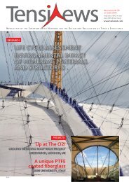
The earth coloured ‘African Pot’, the traditional calabash, as<br />
a melting pot of cultures can be seen as the unique Pan-African<br />
symbol (Fig. 1). This was the main idea of the architects for<br />
the design of the biggest stadium on the African continent.<br />
3<br />
©GRINAKER LTA/INTERBETON JOINT VENTURE<br />
Figure 1:<br />
Arial view of the stadium.<br />
Figure 2.<br />
Plan.<br />
Figure 3.<br />
Construction details.<br />
Figure 4.<br />
Erection of the roof.<br />
Figure 5.<br />
Erection of the facade.<br />
1<br />
© PDNA<br />
8 TENSINEWS NR. <strong>18</strong> – APRIL <strong>2010</strong><br />
Johannesburg<br />
Durban<br />
Port Elizabeth<br />
Cape Town<br />
Johannesburg<br />
South African 4South Africa’s successful application for hosting the World Cup has resulted<br />
in the construction of several new stadia. The construction or modernization<br />
of these new arenas coincides with novel ideas for the design. In all cases the<br />
roofs play the major role when it comes to the question of unique design and<br />
easy recognition. The roof is the most important element to create the<br />
stadium look.<br />
Soccer City Stadium<br />
The stadium can accommodate 94.000 spectators. The three tier levels<br />
can be reached via curved inner and outer ramps. The Stadium is located<br />
in close neighbourhood to Soweto. Historical parts of the upper tier level<br />
of the old stadium (built in 1987), where Nelson Mandela was present<br />
during important events have been retained and conserved, whereas the<br />
whole rest of the stadium has been newly built.<br />
Specially arranged coloured façade-panels with 6 colours and 3 textures<br />
on the surface changing from darker to lighter colours on the top as well as<br />
the light coloured upper membrane blend into the natural surroundings of<br />
the typical local ‘mine-dumps’. Starting from the architects images and<br />
ideas, schlaich bergermann und partner designed and developed the<br />
optimised structure for the huge roof and the façade structure in close<br />
corporation with the structural engineers of the concrete tiers structure,<br />
PDNA of Johannesburg. The overall shell<br />
geometry (roof and façade) derives from a torus<br />
with an outer diameter of 300m which was<br />
defined in section with varying radiuses (Fig. 2).<br />
As the opening of the roof and the surrounding spatial ring truss (the<br />
most important structural element) follow the rectangular shape of the<br />
field and the arrangement of the tiers, both geometries combined create<br />
an impressing 3-dimensional curved structure.<br />
2 3 3<br />
3
schlaich bergermann und partner<br />
Stadium Projects<br />
Since the cable net structures for the Olympic Stadium roof in Munich, we use<br />
all our knowledge and creativity to make the roof of a stadium the star of the<br />
event. This can easily be observed in South Africa. The stadium roofs in Johan -<br />
nesburg (Soccer City), Durban, Port Elizabeth and Cape Town were designed by<br />
structural consulting engineers schlaich bergermann und partner under the<br />
lead of Knut Göppert, already widely known for their special designs.<br />
The 800m long spatial ring truss with its 3 chords (circular sections) is<br />
clad with polycarbonate panels. It is supported by 12 concrete shafts and<br />
16 columns only. The roof cantilever truss (open sections) length over the<br />
tiers is 38m. The cantilevers are clad with arch supported PTFE membrane<br />
on the top side and an open mesh Glass/PTFE membrane on the bottom<br />
side. For the cladding of the inner edge of the roof also polycarbonate<br />
panels were used. Different from many arch supported membrane roofs<br />
for stadia, the soccer city stadium uses a radial arch arrangement. This<br />
considers the comparative small panel size as well as the architectural<br />
idea of the “finger formed clay pot” (Fig. 3 & 4).<br />
The slim shell structure of the façade, designed as curved steel beam is<br />
supported on inclined concrete columns and fixed on the top to the<br />
spatial ring truss. The glass-fibre reinforced 13mm thick concrete façade<br />
panels 1,2m x 3,6m have been fabricated with natural colours and<br />
different textures and arranged exactly according to the architects special<br />
patterning design (Fig. 5).<br />
� Knut Göppert<br />
� k.goeppert@sbp.de<br />
4 5<br />
4 5<br />
� Frank Simon<br />
� f.simon@sbp.de<br />
Roof structures for enormous spans had to be developed, often with a depth<br />
of more than 50 m. Spatial load transfer structures are state of the art when it<br />
comes to efficient and sustainable engineering solutions. Fabrication and<br />
erection aspects influence the early design ideas and lead to unique<br />
installation processes. The authors present the four projects in detail and<br />
provide a view into the future of stadium roof design.<br />
©STEVEN WILBRENNINCK/INTERBETON<br />
Name of the project: Soccer City Stadium Johannesburg<br />
Location address: Johannesburg, South Africa<br />
Client: City of Johannesburg<br />
Function: Multifunctional arena, Stadium<br />
Year of construction: <strong>April</strong> 2006 – February <strong>2010</strong><br />
Structural Engineers Roof and Facade: schlaich bergermann und partner,<br />
Stuttgart<br />
Structural Engineers Concrete Structure: PDNA, Johannesburg<br />
Architects: Boogertman, Urban Edge and Partners<br />
(Bob van Bebber / Piet Boer), Johannesburg<br />
Wind Engineering: Wacker Ingenieure, Birkenfeld<br />
Main contractor: GLTA/Interbeton, South Africa / Netherlands<br />
(Joint Venture)<br />
Main contractor roof: Cimolai, Pordenone / Italy<br />
Fibre concrete subcontractor: Rieder, Austria<br />
Membrane manufacture and installation: Hightex, Rimsting / Germany<br />
Supplier of the membrane material: Verseidag-Indutex, Krefeld, Germany<br />
Capacity: 94.000 seats<br />
Steelwork: 9.000 tonne<br />
Roof area: Upper membrane: 23.000m² PTFE/Glass (glass fiber fabric<br />
coated with Dyneon PTFE and Dyneon Fluorothermoplastics)<br />
Lower mesh membrane: 25.000m² PTFE/Glass(glass fiber fabric<br />
coated with Dyneon PTFE and Dyneon Fluorothermoplastics)<br />
Vertical mesh membrane: 2.000 PES/PVC<br />
Glazing: 12.000m² Polycarbonate, t=12mm<br />
Facade area: 35.000m² fibre reinforced concrete, t=13mm<br />
TENSINEWS NR. <strong>18</strong> – APRIL <strong>2010</strong> 9
As part of the City of Durban´s<br />
redevelopment program the<br />
projected World Cup stadium was<br />
chosen to create an icon for the<br />
KwaZulu Natal region and<br />
Durban, being the 2 nd largest city<br />
in South Africa. The ambitious<br />
plan to gain international<br />
attention enabled the lead<br />
Architects von Gerkan Marg und<br />
Partner, Berlin, the lead structural<br />
engineers schlaich bergermann<br />
und partner, Stuttgart and BKS,<br />
Durban to design an outstanding<br />
stadium of unprecedented scale<br />
and beauty and therefore won<br />
the design competition. The<br />
scope of work for the structural<br />
engineers did also include all<br />
erection engineering, the<br />
checking of all workshop<br />
drawings and surveys, the site<br />
and fabrication supervision as<br />
well as the technical lead for the<br />
tender process and the imple -<br />
mentation phase for the client.<br />
10 TENSINEWS NR. <strong>18</strong> – APRIL <strong>2010</strong><br />
1<br />
Durban<br />
Moses Mabhida Stadium<br />
2 2<br />
3 3<br />
The multipurpose stadium with a<br />
possible capacity of 85.000 seats<br />
features a unique roof structure<br />
of 46.000m² of Glass/PTFE<br />
membrane being prestressed<br />
against a cable net. The cable net<br />
is tensioned against two steel<br />
compression rings along the<br />
perimeter of the stadium and a<br />
mayor arch structure with 103m<br />
height and 360m distance be -<br />
tween its foundations (Fig. 2- 3).<br />
Governed by the high wind loads<br />
in close proximity to Durban´s<br />
coastline the membrane<br />
structure required a rather dense<br />
cable support structure to<br />
minimize the membrane stresses.<br />
To achieve a global safety factor<br />
greater than 5, as stipulated in<br />
the European design guide for<br />
tensile surface structures, the<br />
distance in plan between ridge<br />
and valley cables needed to be<br />
reduced to a maximum distance<br />
of only 8m at the outside<br />
perimeter (compression ring).<br />
Often the installation procedures<br />
reduce the material strength<br />
remarkably, especially when<br />
effective quality control is<br />
missing. To achieve the required<br />
safety factor in reality, a detailed<br />
investigation into the strength<br />
deterioration due to, manu fac tu -<br />
ring, handling, packing and<br />
installation was undertaken, to<br />
overcome the critical strength<br />
reduction due to folding of the<br />
glass/PTFE material. In order to<br />
not accept mishandling of the<br />
material the braking strength of<br />
the virgin material and the<br />
handled material was compared<br />
in several stages, even by taking<br />
out installed sub panels for<br />
testing. The form found and<br />
most effective structural shape of<br />
the stadium roof drains 75% of<br />
the rain water directly towards<br />
the gutter located at the<br />
compression ring.<br />
The remaining water is firstly<br />
running towards the tension ring,<br />
before it can be redirected<br />
naturally towards the com pres -<br />
sion ring in the areas underneath<br />
to the arches. To achieve this the<br />
membrane shape and the gutter<br />
located on the tension ring had to<br />
be form found in a specific<br />
manner. All membrane connec -<br />
tions close to the gutter were<br />
connected using continuous<br />
cables and cable clamps requiring<br />
local membrane cut outs with<br />
unsupported membrane edges.<br />
These locations were designed<br />
and tested using bias cut and<br />
straight cut membranes. The<br />
installation of the membrane<br />
panels was following structural<br />
design criteria that were derived<br />
using the local wind data of<br />
prevailing winds. Due to the open<br />
shape of the partly installed roof<br />
the wind loads during construc -<br />
tion and therefore membrane<br />
stresses were higher than for the<br />
final building, even though<br />
reduced wind pressures for<br />
construction stages were used.<br />
Several construction stages, also<br />
for the membrane installation,<br />
had to be assessed in the wind<br />
tunnel.<br />
� Knut Göppert<br />
� k.goeppert@sbp.de<br />
� Markus Balz<br />
� m.balz@sbp.de<br />
Figure 1. Arial view of the stadium.<br />
Figure 2. Equilibrium of tension and<br />
compression forces.<br />
Figure 3. Erection of the mayor arch structure<br />
and final interior view.<br />
Name of the project: Moses Mabhida Stadium, Durban<br />
Location address: Durban, South Africa<br />
Client: City of Durban - eThekwini Municipality<br />
Function: stadium<br />
Year of construction: March 2006 – November 2009<br />
Structural Engineers Roof: schlaich bergermann und partner, Stuttgart<br />
Structural Engineers Concrete Structure: BKS Durban, South Africa<br />
Architects: gmp Architekten, Berlin<br />
Consulting engineer for the membrane: Birdair, Buffalo<br />
Wind Engineering: Wacker Ingenieure, Birkenfeld<br />
Main contractor: JV WBHO / Group 5<br />
Main contractor Roof: Pfeifer Seil- und Hebetechnik, Memmingen<br />
Membrane subcontractor: Birdair, Buffalo<br />
Supplier of the membrane material: Saint Gobain, Merrimack, NH<br />
Capacity: 70.000 World Cup mode; 54.000 legacy temporary seats will<br />
be substituted by conference facilities; 85.000 Olympic mode<br />
Steel work: 2.860 tonne main arch,<br />
2.700 tonne compression ring and columns<br />
Cable structure: 550 tonne<br />
Membrane surface: 46.000m²<br />
Roof area: 39.000m² (vertical projection)
Port Elizabeth<br />
Stadium of the “windy city”<br />
1<br />
Port Elizabeth, one of the South African cities selected to host the games of<br />
<strong>2010</strong> Fifa World Cup had the special challenge of building a world class<br />
sports arena. A German design team started in 2005 the planning of the<br />
stadium, aiming to design a signature landmark that could be at the same<br />
time a structurally and economically meaningful building.<br />
Contractors from South Africa, USA, Australia, Japan and Kuwait worked<br />
during 42 months in its construction, until its completion in <strong>April</strong> 2009.<br />
Particular boundary conditions, as the frequent wind and an extremely<br />
corrosive environment, due to high temperatures combined with a high<br />
degree of humidity and salt content of the air required individual solutions<br />
from the very initial design of the roof until its final completion.<br />
The architectural planning team was inspired by the privileged site, an<br />
elevated platform next to the North End Lake, to create a building that<br />
could be remarkable and visible from afar.<br />
Roof and facade had a fundamental role in the planning process –<br />
integrated in an interesting interplay of concave and convexes forms,<br />
both created not only the stadium identification, but functionally<br />
they also provided a wind shelter for the internal stands. In addition to the<br />
wind tunnel tests to determine the wind loads acting onto the roof, a wind<br />
comfort study for the stands and the field was performed to provide the<br />
maximal comfort to the spectators as well as the owner’s confidence in the<br />
project. Again, schlaich bergermann und partner’s approach to control all<br />
stages of a project, from first design ideas until the last bolt being placed,<br />
was a fundamental contribution to the success of the project. Thirty-six<br />
triple chord steel girders of spatial tubular framework, cantilevering over<br />
the grandstands, carry the roof and simultaneously articulate the unique<br />
outer appearance of the stadium like petals of a flower growing on top of<br />
monumental facade columns and tapering off towards the centre of the<br />
2 2<br />
3 3 3<br />
stadium, all together forming a calyx in a ridge and valley shape (Fig. 2).<br />
The girders, clad with aluminium standing seam sheeting, form the ridges.<br />
Fabric panels of PTFE coated glass fibre membrane, spanning between the<br />
girders, form the valleys and dewater the roof. The alternation of<br />
translucent and opaque material is visible as a series of illuminated<br />
surfaces: at day from inside - at night from outside. A ring beam connecting<br />
the top points of the girders forms the inner edge of the membrane bays<br />
and carries a circular walkway integrating the flood light system (Fig. 3).<br />
Polysyloxane based corrosion protection with high UV resistance has been<br />
chosen for the structural steelwork; movable and accessible parts are<br />
duplex coated. All relevant details of connections of the membrane and the<br />
aluminium sheeting had to pass a long term salt spray test to demonstrate<br />
their applicability. Port Elizabeth stadium construction performed an<br />
interesting experience in the coordination of international suppliers and<br />
contractors, in a complex but successful example of globalisation. The steel<br />
framework girders were prefabricated in Kuwait and shipped to Port<br />
Elizabeth in parts. Next to the bowl, the girders were assembled on<br />
false-work templates considering tight tolerances. After surveying, the 45m<br />
long 25m wide curved 55 tonne trusses were lifted in position on top of the<br />
R/C structure by a crawler crane. Due to a maximum wind speed for the<br />
crane activity, most lifts had to be done in the early morning hours and had<br />
to be finished before the wind frequently started to increase. The<br />
membrane panels, fabricated in Japan, were unfurled on a temporary net<br />
spanning between the girders and pre-tensioned in steps. A big part of the<br />
aluminium sheeting has been installed by climbers sheet by sheet since<br />
only the area next to the facade was accessible by a movable shoring tower.<br />
Besides accommodating sports events like a <strong>2010</strong> quarter final, the stadium<br />
also houses conference rooms, offices, gastronomy and corporate boxes.<br />
The major legacy of Port Elizabeth stadium is, therefore, its remarkable<br />
contribution to the revitalization of the quarters around North End Lake,<br />
transforming the area with its architectural presence and opening its doors<br />
for the public, even beyond the final whistle of the 3 rd place playoff match<br />
in South Africa this year.<br />
� Knut Göppert<br />
� k.goeppert@sbp.de<br />
� Lorenz Haspel<br />
Figure 1. Arial view of the stadium. © GLTA<br />
Figure 2. Plan.<br />
Figure 3. Erection of the roof.<br />
Name of the project:The roof for the new <strong>2010</strong> WorldCup Stadium, Port Elizabeth<br />
Location address: Port Elizabeth, South Africa<br />
Client: Nelson Mandela Bay Metropolitan Municipality<br />
Function: stadium with conference rooms, offices, etc<br />
Year of construction: November 2005 - <strong>April</strong> 2009<br />
Architects: von Gerkan Marg und Partner, Berlin<br />
Design Team Structural Engineers Roof: schlaich bergermann & partner, Stuttgart<br />
Engineers for local coordination: Iliso Consulting, Port Elizabeth<br />
Design Team Roof wind engineering: Wacker Ingenieure, Birkenfeld<br />
Consulting engineer for the membrane: Birdair, Buffalo<br />
General Contractor: Grinaker-LTA / Interbeton (Joint Venture)<br />
Contractor Steel and Membrane structure: Taiyo Membrane Corporation<br />
Birdair, Australia/USA<br />
Contractor Aluminium Cladding: CC George Roofing, Cape Town, South Africa<br />
Contractor Steel manufacture: ABJ, Kuwait<br />
Steel Structure: 2300 tonne<br />
Aluminium Cladding: 22.500m²<br />
Material: Glass-PTFE membrane<br />
Capacity: 48.600 seats, thereof 45.940 permanent<br />
Membrane surface: 22.000m²<br />
Covered area: 30.000m²<br />
Costs Roof: ca. 22mio €<br />
TENSINEWS NR. <strong>18</strong> – APRIL <strong>2010</strong> 11
©BRUCE SUTHERLAND<br />
1<br />
The new Stadium in Cape Town is set into the spectacular scenery of the<br />
Table Mountain, Lions Head, City Bowl and Atlantic Ocean. Although the<br />
location within the Greenpoint Common Area was controversial at the<br />
beginning – set in-between a golf course, cricket grounds, tennis courts,<br />
etc. – the completed building shows a respectful integration into its<br />
environment and surroundings. The design was driven by two main<br />
criteria: first, the city set forth specific criteria, which limited the<br />
maximum height of the building. The second parameter was the<br />
dominating impression of the horizontal silhouette of the Table<br />
Mountain. A simple spoke-wheel roof, as has been done many times<br />
before for other stadiums, was not possible due to the required height of<br />
the columns, which would have exceeded the limit by far. Even a<br />
cantilevered roof would have required a construction height at the outer<br />
edge that would have exceeded the set limit. Furthermore, to create a<br />
counterpoint to the Table Mountain, the eaves of the building should<br />
have an intentional curvature to their shape.<br />
The final result is a roof design consisting of a strongly undulating<br />
compression ring, a suspended cable net and an elevated truss girder<br />
structure. The latter one stabilizes the "soft" cable net in case of<br />
unbalanced loads and lifts up the actual roof surface to an elevation that<br />
allows for natural dewatering to the outside. Since the suspension roof<br />
requires additional weight to bear uplift forces, the entire cladding<br />
system of the roof was designed as glazing, a first for any stadium roof.<br />
The First National Bank Stadium<br />
(Soccer City Stadium) in<br />
Johannesburg is being completely<br />
renovated. The design of the new<br />
exterior facade is based on a<br />
typical African vessel, the<br />
calabash. It has been possible to<br />
create the new roof shape, which<br />
encircles the stadium, through the<br />
use of PTFE/glass fiber membranes<br />
coated using Dyneon PTFE and<br />
Dyneon Fluorothermo plastic<br />
dispersions. A further highlight for<br />
the <strong>2010</strong> World Cup will be<br />
created directly at the foot of<br />
Table Mountain in Cape Town,<br />
12 TENSINEWS NR. <strong>18</strong> – APRIL <strong>2010</strong><br />
DYNEON<br />
Coated membranes for<br />
the Soccer City Stadium<br />
and the Cape Town Stadium<br />
Fig. 1 Translucent façade of the Cape Town Stadium<br />
where the Green Point Stadium<br />
will be replaced by a new and<br />
larger stadium. A multifunctional<br />
Cape Town<br />
The new<br />
Cape Town<br />
Stadium<br />
A mesh membrane, located underneath the truss girders and spanning<br />
between the radial cables, closes the roof void from below and positively<br />
influences the visual appearance, acoustic behaviour and wind exposure<br />
level. Only the cantilevering part of the structure, from the ring cable to<br />
the inner roof edge remains uncovered from below (Fig. 2). The glazing<br />
above this area is clear, whereas on the rear part of the glazing (with the<br />
membrane underneath) a layer of white print was applied to its lower<br />
surface. Great importance was also attached to the design and<br />
appearance of the roof surface, since it is visible from many highly<br />
frequented observation points as well as from the higher situated<br />
properties of Greenpoint, and therefore acts as a "facade" (Fig. 3).<br />
The lateral facade consists of an off-set steel structure made of vertical<br />
and horizontal beams, which are connected to the concrete structure<br />
behind by diagonal struts. The horizontal beams, curved in plane, are<br />
arranged in front of the facade surface and therefore form a visible<br />
horizontal division of 14 strips. The steel structure is covered with a silver<br />
coloured mesh membrane. Its doubly-curved single panels form an<br />
almost chameleon-like skin, which intriguingly changes the appearance<br />
of the stadium in colour and translucence depending on the exterior<br />
lighting conditions. Due to the seaside location and typically extreme<br />
wind conditions in Cape Town the wind loading was, of course,<br />
the governing aspect of the design of the structure. A particularity for the<br />
design was that not only the pressure values according to the standards<br />
Preparations in South Africa, venue for the <strong>2010</strong> FIFA World Cup,<br />
are in full swing: several stadiums are currently being renovated<br />
and built from scratch. Planners are making ever greater use of<br />
membrane architecture, with all its advantages, enabling<br />
innovative forms of design. Two current examples are the First<br />
National Bank Stadium (Soccer City Stadium) in Johannesburg and<br />
the new Cape Town Stadium in Cape Town.<br />
arena is to take shape here under<br />
the name of "Cape Town<br />
Stadium". The flowing facade of<br />
the stadium consists of an<br />
abstract, light membrane<br />
structure composed of concave<br />
elements having a large surface<br />
area. The translucent surface<br />
absorbs and reflects daylight in a<br />
unique fashion.<br />
At sunset the stadium shimmers<br />
red, blue on a summer's day and<br />
gray if the weather is bad. The<br />
wave-shaped roof will be coated<br />
with laminated safety glass and<br />
covered on the inside with a<br />
translucent membrane. Technical<br />
elements for acoustics and lighting<br />
can be integrated between the
©GMP ATCHITECTS<br />
had to be taken into account, but also the specific topographic conditions<br />
at that particular location between Table Mountain, Signal Hill and the<br />
close sea. The final wind loads acting on the structure had to be<br />
investigated by two different wind tunnel tests. The first one used a<br />
topographic model to determine the specific local wind and gust<br />
conditions, while the second one applied these first results to the model<br />
of the stadium building.<br />
Another challenge specific to this structure was the interaction between<br />
cladding (glazing) and deformation. Despite the stiffening effect of the<br />
truss girders, the resulting deformations of the structure are not<br />
negligible; this means that there is significant amount of warping and<br />
bias/distortion in the substructure of the glazing. To allow for this,<br />
numerous tests had to be conducted to develop the bearing details for<br />
the glazing, which allow for the required relative movement between the<br />
glass panes and sub structure.<br />
A perfect interplay between design architects and the structural<br />
engineers from schlaich bergermann und partner as well as the smooth<br />
cooperation between the engineers of the roof and façade structure with<br />
our colleagues responsible for the reinforced concrete structure formed a<br />
strong base for the successful completion of the project. Again, it has<br />
been proven that it is fundamental for projects of this complexity to have<br />
design, erection engineering, site and fabrication supervision as well as<br />
the checking of all workshop drawings concentrated in the hands of the<br />
lead structural engineers of the roof.<br />
� Thomas Moschner<br />
� t.moschner@ sbp.de<br />
2<br />
glass and the membrane.<br />
The company Verseidag Indutex<br />
GmbH in Krefeld, which<br />
specializes in textile<br />
architecture, is supplying the<br />
textile support structure of<br />
duraskin® membranes. Use of<br />
different coating techniques on<br />
the different support and cover<br />
materials ensures optimum<br />
protection, as in a "second skin".<br />
The duraskin® membranes<br />
consist of coated glass fiber<br />
fabric, which offers tensile<br />
strenghts of more than one<br />
tonne per meter width and only<br />
weighs 0,5 kg per square meter.<br />
The coating with Dyneon PTFE<br />
and Fluorothermoplastic<br />
materials provides the<br />
membrane with the special<br />
characteristics needed for the<br />
tough task within the stadium<br />
construction. The surface of the<br />
coating is very smooth and<br />
� Knut Göppert<br />
� k.goeppert@sbp.de<br />
offers permanent resistance to<br />
the most varied weather<br />
conditions, as demonstrated by<br />
many years experience in<br />
different climatic zones.<br />
Dyneon PTFE features<br />
resistance to almost all<br />
chemicals along with good<br />
mechanical properties.<br />
An important advantage of<br />
PTFE coatings is that they<br />
require neither plasticizers nor<br />
stabilizers, which evaporate<br />
over time, leading to<br />
embrittlement. The<br />
membrane coated<br />
with Dyneon PTFE<br />
and Dyneon<br />
Fluorothermoplastic<br />
remains<br />
smooth and elastic.<br />
After several years<br />
Fig. 2 Detail of waveshaved<br />
roof of the<br />
Cape Town Stadium.<br />
Figure 1. Arial<br />
view of the stadium.<br />
Figure 2. Roof<br />
acting as facade.<br />
Figure 3.<br />
Visualisation.<br />
3<br />
Name of the project: The new Cape Town Stadium<br />
Location address: Green Point Common, Cape Town, South Africa<br />
Client: City of Cape Town<br />
Function: Multifunctional arena, Stadium<br />
Year of construction: 2007-<strong>2010</strong><br />
Structural Engineers Roof and Facade: schlaich bergermann und partner,<br />
Stuttgart<br />
Structural Engineers Concrete Structure: BKS Bellville, South Africa<br />
Architects: Stadiumarchitects<br />
(gmp Berlin, Louis Karol, Point Architects both Cape Town)<br />
Consulting engineer for the membrane: Birdair, Buffalo<br />
Wind Engineering: Wacker Ingenieure, Birkenfeld<br />
Main contractor: Murray & Roberts / WBHO (Joint Venture)<br />
Contractor Roof: Pfeifer / Birdair (Joint Venture)<br />
Contractor Facade: Hightex / Mostostal (Joint Venture)<br />
Start design - Completion <strong>April</strong> 2006 – December 2009<br />
Capacity: 68.000 World Cup mode, 55.000 afterwards<br />
(temporary seats will be substituted by lounges)<br />
Roof area Glazing: ca. 37.000m², ca. 9000 single panes (2x8mm TVG)<br />
Roof area Lower membrane: ca. 35.000m² mesh fabric PES/PVC<br />
Facade area membrane: ca. 27.000m² mesh fabric PTFE/Glass<br />
(glass fiber fabric coated with Dyneon PTFE and Dyneon Fluorothermoplastics)<br />
service there will be no cracks<br />
which could allow bacteria and<br />
mould to become established.<br />
Even under conditions of<br />
limited rainfall a shower is<br />
sufficient in order to clean the<br />
roof. The transparency of the<br />
fabric guarantees optimum<br />
light conditions for fans and<br />
players during daylight.<br />
� Helmut Frisch<br />
� dyneon.europe@<br />
mmm.com<br />
� www.dyneon.com<br />
Images, where not noted different, by schlaich bergermann und partner<br />
schlaich bergermann und partner - Structural Consulting Engineers<br />
STUTTGART . BERLIN . NEW YORK . SAO PAULO - www.sbp.de<br />
Contractor<br />
of the membranes<br />
Birdair, Inc<br />
For the stadia in Cape Town, Durban<br />
and Port Elizabeth Birdair, Inc was<br />
involved as contractor for the<br />
membranes. Birdair, Inc. is a leading<br />
specialty contractor of light weight<br />
long-span roofing systems and tensile<br />
structures throughout the world,<br />
providing design-build solutions for<br />
architects and clients in all aspects of<br />
project design, engineering,<br />
installation and maintenance.<br />
Lightweight long-span roofing<br />
systems and cable struc tures can be<br />
attached to any building envelope and<br />
offer aesthetic and functional options<br />
to complement any exterior design.<br />
Birdair, based in Buffalo, NY, is a<br />
member of the Taiyo Kogyo Group,<br />
with operations serving North and<br />
South America and other inter national<br />
locations. (www.birdair.com)<br />
TENSINEWS NR. <strong>18</strong> – APRIL <strong>2010</strong> 13
RESEARCH<br />
IMS<br />
Research<br />
Project<br />
“Batsail”<br />
Initial Experiment<br />
As a first step a Batsail membrane with 5 fibre<br />
rods under compression was exposed to several<br />
load cases at different positions of the<br />
membrane surface to test the deformation of<br />
the structure compared to a simple 4-point sail.<br />
The results were as expected: the higher the<br />
pre-compression in the glass fibre bats, the<br />
more homogeneous the behaviour with less<br />
deformation over the whole surface of the<br />
membrane could be noticed (Fig. 1).<br />
As the first experimental Batsail was too<br />
complex as a structure with too many possible<br />
influencing factors, it appeared impossible to<br />
simulate the behaviour within a computational<br />
model. Therefor it was decided to initiate a<br />
smaller second advanced experiment with one<br />
single glass fibre bat anchord at the edge cable<br />
without cantilivering effect.<br />
Second Experiment<br />
Within a scaffold cube of 3m edge length a<br />
4-point shallow hypar was erected. At each<br />
corner point spring balances were adjusted to<br />
measure the tension forces of the Batsail.<br />
A single glass fiber bat was fixed below the<br />
membrane by stitching to exclude the influence<br />
of a pocket. The compression was introduced<br />
by a simple screw shortening the space within<br />
the anchoring steel tube. The membrane was<br />
14 TENSINEWS NR. <strong>18</strong> – APRIL <strong>2010</strong><br />
Hyperbolic membrane structures can be a very charming and aesthetic way to cover smaller areas<br />
such as carports or shading sails. Technologies and detail points for this type of membrane<br />
construction are well developed, with one big challenge: the inwards curved edge cables<br />
narrow the spanned-over space, so only a small area can actually be covered.<br />
To address this problem and to generally widen the possibilities of membrane structures one<br />
of the IMS research projects is the ”Batsail” project, a membrane reinforced with flexible<br />
reinforcement fibre rods, able to take compression forces under buckling state secured and<br />
anchored within the membrane surface itself. In addition the compressed rods can extend over the<br />
edge cables like wings of a bat. They stiffen the membrane edges and maximize the covered space.<br />
The structural behaviour and promising possibilities of this hybrid and form-adaptive structure<br />
were content of research at the IMS and University Anhalt, Germany.<br />
made of one piece to also exclude the influence<br />
of seems (Fig. 2). Before starting to<br />
tension the rod and putting loads onto the<br />
membrane, a laser scan was done. Each step of<br />
change that occurred to the membrane by putting<br />
loads onto it or removing it, was laser<br />
scanned - up to the point of failure of the glass<br />
fibre rod (Fig. 3).<br />
The scans of each measurement case were used<br />
to create the membrane´s surface as computer<br />
model. Projecting a system of grid lines (the<br />
same for each case) on each of the membrane<br />
models provided the possibility to compare -<br />
additionally to the comparison of the measured<br />
forces in the rod and spring balances - the different<br />
scans to each other, at defined positions:<br />
5 in the field and 3 on the rod itself (Fig. 4).<br />
Inserting a load at any position to a membrane<br />
without uncompressed flexible fibre rod, the<br />
membrane´s deformation, especially in the<br />
area of the loading´s placement, will be high,<br />
depending on the load value. Even in uncompressed<br />
condition the fibre glas rod´s compression<br />
force was activated by applying a vertical<br />
load on the membrane´s surface. The bat absorbed<br />
a part of the additional stress in the<br />
structure caused by the load.The deformation<br />
of a membrane without anchored bat will be<br />
much higher. For the tensioned membrane with<br />
uncom pressed fibre glass rod and a load of 90N<br />
a downward deformation of 2,6% (over all positions<br />
1-8) of the maximum diagonal length of<br />
the membrane was monitored. After pre-compressing<br />
the bat, the deformation was reduced<br />
to only 0,9%! So with the help of a compressed<br />
flexible fibre glass bat a significant reduction of<br />
1 2 2 2<br />
1<br />
3 3 4 4<br />
5 6<br />
Figure 1. Initial experiment – membrane<br />
with 5 fibre rods.<br />
Figure 2. Second experiment – installation.<br />
Figure 3. Laser scanning.<br />
Figure 4. scanning results inplemeted in<br />
membrane models.<br />
Figure 5. Second experiment - results.<br />
Figure 6. Computer simulation URS programme.
deformation can be achieved. The introduction<br />
of compression force into the rod anchored at<br />
the edge cables automatically increases the<br />
stress over the whole structure including the<br />
corner points. Thus with the help of the rod the<br />
whole structure can be pretensioned. While<br />
introducing single vertical loads on the membrane<br />
(position 7) the precompression and<br />
pretension is reduced at the bat and the corners.<br />
Less force is transferred to the supporting<br />
structure, even applying additional load to the<br />
surface, while at the same time the deflection<br />
with a load of 20N is only 0,3% and with 90N<br />
only 0,9% (% referring to the diagonal length of<br />
flat membrane). Just load case 5 (membrane<br />
under tension, rod compressed, load of 90N) is<br />
applying additional compression on the bat<br />
and additional tension at the highpoints.<br />
So up to the point where the introduced<br />
prestress and precompression is “used up”,<br />
the deflection is within a comparetively small<br />
range compared to the span. Applying more<br />
load, the compression in the rod increases again<br />
as well as the high point´s stress level. This goes<br />
up to 13% of increase of compression in the rod,<br />
then the snap through point is reached. Before<br />
the rod failed, stresses were increasing everywhere.<br />
A big difference between the forces in<br />
the low points (degreased) and the high points<br />
(increased) was to be noticed. After snap through<br />
all load is hanging on the two high points with an<br />
increase of 15% tension force and an average<br />
deflection of 3,8%. The snap through incident is<br />
clearly predictable by these indicators (Fig.5).<br />
Summary<br />
Structures like the Batsail - with flexible fibre<br />
rods anchored to a membrane - allow us to<br />
enlarge the covered area by “pushing the edge<br />
cables” outside. The main unexpected<br />
advantage is the possiblity to significantly<br />
reduce the deflection under load without having<br />
to increase the prestress level of the membrane<br />
by higher anchoring forces. This enables larger<br />
spans with less deflection, smaller mast<br />
dimensions and foundations. The next step of<br />
reliable structural calculation has yet to be<br />
proven in order to introduce the Batsail into<br />
everydays structures. Therefor the results were<br />
sent to Prof. Dr. Kai-Uwe Bletzinger, at the<br />
Technical University Munich to simulate the<br />
experimental Batsail within his URS (Updated<br />
Reference Strategy) programm . A first simulation<br />
already showes that a Batsail structure can<br />
be accurately modelled (Fig. 6).<br />
� Prof. Dr. Robert Off, Director IMS,<br />
Germany, Anhalt University. (article)<br />
� robert.off@ims-institute.org<br />
� Prof. Dr. Heinz Runne,<br />
Anhalt University, Germany (surveying)<br />
� heinz.runne@ ims-institute.org<br />
� www.ims-institute.org<br />
FORMFINDER Software<br />
"One Click" Cost Estimation<br />
for the architectural design<br />
of membrane structures<br />
ARTICLE<br />
Who knows the price? At each step of the design someone might ask<br />
this question. Especially membrane structures are rarely<br />
documented and analyzed with respect to these (cost) factors.<br />
Due to the vast number of different shapes a comparison was<br />
not possible up to now.<br />
2<br />
The solution introduced here is based on the Formfinder software and opens a<br />
completely new way on the evaluation of different cost factors. The first part of the<br />
solution is a new logical database that contains specific expert’s knowledge generously<br />
provided by Mr. Horst Dürr at “Ingenieursgemeinschaft IF”. The second part is an<br />
incorporating self-learning calculation algorithm that connects specific geometric<br />
components of the design with the so called design "values".<br />
Each design "value" represents a specific view on the intended design. It is important that<br />
each value is refined with the number of matchable data available and is not only<br />
measured in Euros. Also values like uniqueness, complexity factors or geographical values<br />
are part of the consideration. A creation of a sample set of these "values" and a closer<br />
investigation how they influence the cost estimation is a subject of the PhD thesis by Mr.<br />
Nikolay Kim who is working in the Formfinder Software Development Team. The intention<br />
of the self-learning calculation process is to support the designer at each step of the design<br />
and to increase the architectural quality of membrane structures. The integrated design<br />
tool also includes "values" like the shaded area, rain-protected area or simple projects that<br />
have been built already. Especially with respect to the project database the intended<br />
cooperation with Tensinet will also provide more information to the designer.<br />
� Robert Wehdorn-Roithmayr, Formfinder Software GmbH Wien<br />
� mail@formfinder.at<br />
� www.formfinder.at<br />
1 1<br />
Figure 1. Display of the sun-shape area (left) and rain-protected area (right).<br />
Figure 2 ( above) The Formfinder ProjectFinder is also available for any mobile device e.g. iPhone<br />
TENSINEWS NR. <strong>18</strong> – APRIL <strong>2010</strong> 15
Lone Butte Casino<br />
Lights Up the Desert Sky<br />
Chandler, Arizona, USA<br />
The newly constructed Lone Butte<br />
Casino is located south of Phoenix<br />
in Chandler, Arizona and is owned<br />
and operated by the Gila River<br />
Indian Community. Visitors to the<br />
casino are greeted by a spectacular<br />
fabric structure at the main<br />
entrance built by FabriTec<br />
Structures. FabriTec, in conjunction<br />
with Group West Architects and<br />
General Contractor JE Dunn, have<br />
created a custom framed tensile<br />
structure made of Teflon-coated<br />
Fiberglass (PTFE) fabric. The<br />
5-tiered, wrapped panels form the<br />
canopy for the main entrance and<br />
peak at a height of 13,7m. The<br />
panels range in sizes from as much<br />
as 21,3m long to widths of up to<br />
9m. The casino also features two<br />
smaller side-entry structures as<br />
well as an interior fabric structure<br />
for the central court of the building.<br />
The 3 entrances to<br />
the building were<br />
given equal<br />
importance and<br />
were designed with<br />
matching features<br />
both outside and<br />
in the immediate<br />
indoor entry areas.<br />
16 TENSINEWS NR. <strong>18</strong> – APRIL <strong>2010</strong><br />
FABRITEC STRUCTURES<br />
The design of the fabric structure is<br />
unique in that the fabric cladding is<br />
on the underside of the structural<br />
steel elements thus concealing the<br />
steel from view below (Fig. 1).<br />
The cumulative effect of this design<br />
is that the structure looks like<br />
layers of clouds floating above the<br />
entryway. To add to the dramatic<br />
appearance, the structure has been<br />
built with colorful custom uplighting<br />
which automatically<br />
changes and can be controlled for<br />
various degrees of evening light<br />
and for time of year. FabriTec<br />
Structures won at the 2009<br />
International Achievement Award<br />
(IAA) with this project the<br />
Outstanding Achievement award.<br />
� Jay Jensen<br />
� jjensen@usa-shade.com<br />
� www.usa-shade.com<br />
Figure 1. Drawing<br />
construction detail.<br />
Location address: Chandler, Arizona, USA<br />
Client: Gila River Indian Community<br />
Function of building: main entrance Casino<br />
Type of application of the membrane: canopy<br />
Year of Construction: 2009<br />
Architects: Paul Hamel (Group West Architects)<br />
Engineering: FabriTec Structures<br />
Contractor: JE Dunn Construction<br />
Supplier of the membrane material: Saint-Gobain & MultiKnit<br />
Manufacture and Installation: FabriTec Structures<br />
ARQUITEXTIL FHECOR<br />
Architectural concept<br />
Aranda de Duero is a town in<br />
Castille (Spain). A new Arena<br />
was constructed in this town.<br />
The building consists of a<br />
circular grandstand and a global<br />
roof. The roof is partially<br />
retractable in order to adapt the<br />
configuration of the building to<br />
different events. The Arena has a<br />
circular shape in plan with a<br />
diameter of 80,14m. The roof<br />
ETFE<br />
single skin<br />
was designed as a shell<br />
structure. Half of the central<br />
part of the roof is retractable<br />
and has a shape of spherical<br />
sector of 32,90m of diameter in<br />
plan. (Fig 1)<br />
Steel structure – fixed roof<br />
The main structure has a<br />
Schwelder configuration.<br />
A spherical shape supported<br />
only in the perimeter by<br />
1 1<br />
Name of the project: ETFE SINGLE SKIN ARANDA DE DUERO ROOF<br />
Location: Aranda de Duero, Spain<br />
Client: Victoriano del Río<br />
Function of the building: Concerts, sports and bullfighting Arena<br />
Type of application of the membrane: Protection against environmental<br />
hazards and light transmission<br />
Year of construction: 2006<br />
Architectural Design: José Romo (FHECOR Ingenieros Consultores)<br />
José María Lastra (Comercial Marítima L&Z)<br />
Structural Engineers: José Romo (FHECOR Ingenieros Consultores)<br />
Consulting engineer for the membrane: José Romo (FHECOR Ingenieros<br />
Consultores) & José María Lastra (Comercial Marítima L&Z)<br />
Tensile membrane contractor: Comercial Marítima L&Z<br />
Supplier: Nowofol GmbH<br />
Manufacture and installation: Comercial Marítima L&Z<br />
Material: Nowoflon ET 6235 300 μm ETFE<br />
Cover surface: 1.400m²
Spain<br />
Aranda de Duero Roof<br />
neoprene bearings of 300x400x<br />
121mm located over 36 concrete<br />
pillars. The maximum relative level<br />
of the fixed roof is 9,64m. This<br />
gives a ratio height/span of 1/8,3.<br />
The structure conformed by<br />
HEB280 profiles as meridian and<br />
parallel beams. The diagonals of<br />
steel bars 32mm give the shell<br />
behavior of the structure.<br />
Diagonals were prestressed to<br />
ensure efficiency of the system.<br />
The structure has an outer beam.<br />
This element of 0,60m depth and<br />
0,90m width was made in<br />
reinforced concrete working in<br />
tension. The central oculus has in<br />
the perimeter a steel hollow beam<br />
of 745mm width, 700mm depth<br />
and 12mm of thickness. This beam<br />
is working mainly in compression.<br />
The structure is considerably light.<br />
Its slenderness ratio (depth/span)<br />
is 1/285 meanwhile the egg shell is<br />
1/100. (Fig 2)<br />
Steel structure –<br />
retractable roof<br />
Half of the oculus follows the<br />
geometry of the main roof and it is<br />
also fixed while the other half is<br />
movable. (Fig 3 - 4)<br />
In order to unify the global design<br />
of the roof, the retractable part has<br />
the same radius of curvature as the<br />
fixed roof. To have a more clean<br />
view, the structure of the oculus<br />
does not follow the structural<br />
system of the fixed roof. The<br />
movable half spins around the<br />
central vertical axis. (Fig 5)<br />
The movable part is supported in<br />
the central axis and in four wheels.<br />
Two of them are in both edges of<br />
the beam, and the other two at<br />
60 and 120 degrees. Two engines<br />
move the central wheels. The<br />
movable structure is composed by<br />
HEB steel profiles. Both circular<br />
beam and the one in the diameter<br />
have steel hollow section. (Fig 6)<br />
Movable upper half bearing on<br />
fixed bottom half.<br />
ETFE membrane<br />
ETFE has been used as the oculus<br />
roof material to obtain maximum<br />
transparency. Even though Aranda<br />
has snow winter conditions,<br />
the membrane was design as a<br />
single layer. ETFE has a thickness of<br />
300μm. The membrane has a<br />
negative Gaussian curvature, to<br />
resist snow loads as well as wind<br />
suction. Steel arches give shape to<br />
the membrane. Twelve radial<br />
sectors configure the ETFE mem -<br />
brane.<br />
Each of them was fixed to the<br />
meridian beams, and stressed by<br />
elevating the steel arches.<br />
Longitudinal inox 8mm cables<br />
were used to help the membrane<br />
resist snow loads. (Fig 7)<br />
3<br />
Conclusions<br />
Light ETFE has allowed to build a<br />
slender movable roof which could<br />
not be possible with heavier<br />
materials such as glass. Single skin<br />
gives a high level of tran sparency<br />
which was one of the client’s<br />
requirements. One of the main<br />
goals of this design was the<br />
successful combination of ETFE<br />
with a movable structure. (Fig 8)<br />
4<br />
7<br />
2<br />
8<br />
Figure 1. Air views of the roof.<br />
Figure 2. Fixed roof during construction.<br />
Figure 3. Model view of the fixed elements.<br />
Figure 4. Retractable roof in opened and<br />
closed positions schemes.<br />
Figure 5. Top view of the closed oculus.<br />
Figure 6. Movable upper half bearing on fixed<br />
bottom half.<br />
Figure 7. Membrane bottom view.<br />
Figure 8. Interior view and light going through<br />
the oculus.<br />
5<br />
� José Romo Martin, FHECOR<br />
Ingenieros Consultores<br />
� jrm@fhecor.es<br />
� www.fhecor.es<br />
� José María Lastra,<br />
Comercial Marítima L&Z<br />
� jmlastra@arrakis.es<br />
� www.arquitextil.net<br />
TENSINEWS NR. <strong>18</strong> – APRIL <strong>2010</strong> 17<br />
6<br />
7<br />
8
ARTICLE<br />
Case study ‘Tensile surfaces<br />
The present case study – a membrane roof model – took form during a Mastering Research at the<br />
University of Ouro Preto, Brazil and aims to explore the characteristics of the roof construction<br />
system when applied to a particular situation and to analyze the joint work of Engineering and<br />
Architecture on the development of tensile surface structures. It was studied through a particular<br />
method of work – which involves flexible, physical and computational models and from which the<br />
qualitative and structural solutions are derived. In 2007, the model built for this study was awarded<br />
the First Prize at Valmex Structure 2007's competition, organized by Mehler Texnologies in Brazil.<br />
1. Introduction<br />
Tensile surface structures are three-dimensional<br />
systems composed by the association of<br />
membranes and a supporting system (cables,<br />
masts, arches, trusses, etc. normally in steel)<br />
under a tensile state. Having minimal weight<br />
when comparing with the supported load, these<br />
structures are very flexible, a result of the<br />
substitution of the material mass by the<br />
appropriate form to achieve stability. They<br />
introduce a unique structural approach, in which<br />
the form derives from the flow of forces in the<br />
structure. Thus, the stability, performance and<br />
efficiency of the system are dependent on the<br />
geometry, the pre-stress state and the<br />
continuous and integrated work of all the<br />
structural components.<br />
This approach represents a major challenge to<br />
architects and engineers: the structural solution<br />
needs an accurate design, the knowledge on the<br />
system’s conditions and parameters and,<br />
besides that, it must incorporate the structural<br />
analysis to the conception of the project.<br />
Therefore, the design process in this case is<br />
different from the traditional one, as it should<br />
concentrate the efforts of a multidisciplinary<br />
team (architects, engineers, manufacturers etc),<br />
becoming the result of this team’s interaction<br />
since the beginning. Consequently, the quality<br />
of the spatial and structural solution and the<br />
production of accurate information for the<br />
partially industrialized building process are a<br />
result of the dialogue among the members of<br />
the team and the integration of their work<br />
actions.<br />
Figure 1. Amphitheatre square of the Federal University of Ouro Preto<br />
<strong>18</strong> TENSINEWS NR. <strong>18</strong> – APRIL <strong>2010</strong><br />
2. Method of work<br />
In this case study, the particular method of work<br />
used comprises the conception of the project as<br />
well as the design process. The conception aims<br />
to set up the project’s guidelines or, in other<br />
words, to understand and define the use,<br />
activities and the identity of the object that will<br />
be built, such as the building site’s qualities and<br />
its characteristics (views, topography, influence<br />
of the wind/sun, neighbourhood, relation with<br />
the landscape and city, and the local laws). The<br />
design process includes physical and<br />
computational modelling and permits the<br />
development of the system’s equilibrium<br />
configuration, gradually exploring the benefits<br />
of having Architecture and Engineering working<br />
together.<br />
The physical modelling can be accurately<br />
carried out and allows the investigation of<br />
the geometry and the behaviour of the<br />
components under a tensile stress field.<br />
However, the method of using flexible physical<br />
models was indirect in this case study. That<br />
means it was based on the identification and<br />
mapping of the most important characteristics<br />
of the constructive system (geometry and<br />
integrated work of the components under a<br />
tensile state) for later observations and<br />
qualitative analysis of the system’s behaviour.<br />
The dimensions and parameters involved on the<br />
physical model and the ones of the real<br />
structure are the same, but there is no<br />
geometric factor to establish a relation between<br />
the material’s properties (unit weight and load),<br />
a fact that could turn evaluation into a<br />
simplified representation of the reality.<br />
The computational models comprise the<br />
engineering of the structure, including the<br />
selection of the materials and the analysis and<br />
design of the system. The Density Force Method<br />
and the Finite Element Method were used when<br />
studying this roof. They made possible the<br />
modelling of the initial surfaces (form finding)<br />
and the preliminary non-linear analysis of all the<br />
structure, refining the research on the<br />
equilibrium configuration of the proposed<br />
model.<br />
2.1 Conception of the design<br />
or guidelines of the project<br />
The site chosen to reveal the proposed covering<br />
model is the amphitheatre square of the Federal<br />
University of Ouro Preto, which is a large<br />
strategic area, situated in the centre of the main<br />
campus (Figure 1). Within this academic<br />
context, the proposed project intends to give<br />
visibility and a purpose to the place, stimulating<br />
the local use under different weather conditions<br />
– a cultural, academic or ephemeral use.<br />
The proposed configuration occupies an area<br />
of 2212m² and is composed by two surfaces:<br />
a permanent one (external) and a retractable<br />
one (internal). This creates an appropriate<br />
solution: it protects from rain or sun, provides<br />
the experience of open and close spaces,<br />
permits occasional changes and offers flexibility<br />
towards the most different uses. It also explores<br />
the possibilities for natural lighting and<br />
ventilation of the large free space as well as the<br />
openings to the nice views and relation with the<br />
landscape. A frequent use will improve the<br />
safety of the place.<br />
2.2 Design process<br />
The first stage of the design process comprised<br />
the insertion of the structural project on the<br />
local physical context using physical models.<br />
The initial models, with scale of 1:500 (Figures 2,<br />
3), explores different structural configurations<br />
and allows the intuitive understanding of the<br />
global system. The models on scales 1:200<br />
(Figure 4) and 1:100 (Figures 12, 13) provide a<br />
more detailed comprehension. The 1:500 and<br />
1:200 models were built with nails, fishhooks,<br />
cotton thread, nylon fabric from woman’s<br />
stocking and cardboard for their bases. For the<br />
1:100 model, paper, cotton, steel thread and<br />
hardboard for the base were employed.<br />
The first proposed configuration - Study 1<br />
(a 17x<strong>18</strong>x5cm flexible model built on a 1:500<br />
scale) presents the system’s support and the
structures’ design process<br />
permanent external roof (Figure 2). A threedimensional<br />
system supports the top of this<br />
roof. It is supported by four tall rigid masts and<br />
rigid bar elements, with no continuity, inserted<br />
in a continuous net of tensile cables and<br />
defining a stable and articulated spatial system<br />
(Tensegrity’s Principle). The system is associated<br />
to two rigid rings: the inner ring, connected to<br />
cables, and the outer ring, connected to the rigid<br />
bars. This association brings more stability and<br />
stiffness to the system.<br />
On the second proposal - Study 2<br />
(a 17x<strong>18</strong>x5cm flexible model built on a 1/500<br />
scale) the top of the roof is also supported by<br />
the three-dimensional system and the basis is<br />
still sustained by the same tall masts (Figure 3).<br />
The main difference is that the basis is now at a<br />
higher position in reference to the ground due<br />
to shorter masts added to the model. Another<br />
difference resides in the fact that the spatial<br />
system is supported by three tall independent<br />
masts that are no longer rigid but present a<br />
hinge and tensile cables. The three-dimensional<br />
pin-ended mast’s configuration is a stable shape<br />
in space that avoids the flexural moment. The<br />
compressed mast and the two tensile cables<br />
also enable the reduction of the structure’s<br />
weight, increasing its efficiency.<br />
The Study 2 was chosen to give continuity to<br />
the research on the geometry and behavior of<br />
the roof due to the simplicity and the<br />
challenging balance situation of the supporting<br />
system in addition to the search for the<br />
integration of the proposed tensile membrane<br />
structure with the landscape.<br />
Hence, a new flexible model was created (scale<br />
1/200, 50x50x10cm) in order to study the<br />
complete roof. This Study 2 (1 st adjustment)<br />
revealed the necessity of some modifications on<br />
the supporting system (Figure 4). Thus, the<br />
spatial system received a central flying mast<br />
and the rigid bar elements were connected to<br />
two rigid rings. The central flying mast’s role is<br />
to support the high points of the convertible<br />
surface and by doing so it becomes the central<br />
element of the spatial supporting system. The<br />
two rigid rings have different diameters and are<br />
set on different planes in order to permit the<br />
overlapping and the support of the roofs. The<br />
complete roof also has different arrangement<br />
and behaviour, being now composed by two<br />
anticlastic surfaces (double curvature in<br />
opposite directions). The external permanent<br />
surface is a cone shape, with its top supported<br />
by the internal ring and its basis by the small<br />
Figure 2. View flexible model : three-dimensional of flexible<br />
model – Study 1, scale 1/500 - 1. Permanent covering: Support<br />
system: 2. cables- 3. rigid rings - 4. bars - 5. tall masts<br />
and tall masts. The internal convertible roof<br />
presents a radial array of nine modules of<br />
saddle-shaped form. The top of the flying mast<br />
supports the roof’s centre and cables anchored<br />
to nine points of both external rings supporting<br />
the roof’s basis. When closed, the centrally<br />
retractable surface is protected by a glass roof.<br />
The mechanisms responsible for the movement<br />
of the internal roof are activated by sliding<br />
engines (tractors) that connect the membrane’s<br />
edges to the cables. These tractors, driven by<br />
synchronized electric engines, move freely along<br />
the cables (which are supported by the top<br />
floating mast and the rings) opening and<br />
tensioning or closing the membrane roof.<br />
However, to make the opening and tensioning<br />
of this surface possible, the flying mast may<br />
have a retractile mechanism that allows the<br />
height adjustment of the system.<br />
ARTICLE<br />
Figure 3. View flexible model : three-dimensional of flexible model<br />
– Study 2, scale 1/500 - 1. Permanent covering: Support system: 2.<br />
cables- 3. rigid rings - 4. bars - 5. tall masts - 6. small masts<br />
The second stage of this process included the<br />
registration and the computational modelling of<br />
the developed proposed system: Study 2<br />
(1 st adjustment). It involves the initial surfaces’<br />
modelling (form finding) and the system’s<br />
preliminary analysis.<br />
Initially, the surfaces were modelled through<br />
the Force Density Method using Densalfa,<br />
software developed by Vinícius de Oliveira<br />
(OLIVEIRA, 2003). The force density is an initial<br />
tensile force based in a constant relation<br />
between force and the length of each bar<br />
element, allowing an internal equilibrium of prestress<br />
forces. In this mathematical<br />
approximation, the equilibrium form of the<br />
surface relates the geometry and an internal<br />
tensile stress field. Thus, the membrane surface<br />
was discretised as a cable net by the definition of<br />
a net mesh composed by radial and circum -<br />
Figure 4. Views flexible model: Study 2 (1 st adjustment), scale 1/200; Mechanisms responsible for the movement of the internal roof<br />
1. Permanent covering - 2. Convertible covering; Support system: 3. tall masts - 4. small masts - 5. cables - 6.rigid rings - 7. rigid bars - 8. flying mast -<br />
8. cables that support sliding tractors - 9. cables that support sliding tractors – 10. tractors<br />
TENSINEWS NR. <strong>18</strong> – APRIL <strong>2010</strong> 19
ARTICLE<br />
ferential cable elements and the spatial coor -<br />
dinates of the anchoring points. Then, the force<br />
density was applied to the cable elements in<br />
both directions. In this method, the simplified<br />
equations do not have parameters that refer to<br />
the net material. However, it describes the<br />
spatial form and allows the understanding of its<br />
behaviour and the parameters that govern the<br />
surface’s equilibrium shape: the double cur va -<br />
ture, the curved edge and the pre-stress forces.<br />
Since the form follows the stress flow, on Figure<br />
5, it is possible to observe the series of adjustments<br />
made on the curvatures of the permanent<br />
surface that resulted from changes in the applied<br />
pre-stress present in the net’s internal field and<br />
edge cables. If the tensile force applied to the<br />
edge cable is higher than the one on the net’s<br />
inner tensile field, the inner surface will present a<br />
smoother curvature, becoming less warped.<br />
However, if the level of this tensile force decreases,<br />
the inner surface will suffer a contraction<br />
modifying its form and increasing the<br />
warping of the surface and the edge cable’s sag.<br />
The final configuration and the surfaces’ tensile<br />
stress field were defined by the comparison and<br />
overlapping of the surfaces developed through<br />
the Force Density Method and the images of the<br />
physical model (Study 2 - 1 st adjustment)<br />
(Figure 6). The final three-dimensional surfaces<br />
were exported to another software, which<br />
permitted their association to the system’s<br />
support axis, and then exported to Ansys®<br />
for the preliminary analysis (Figure 7).<br />
The supporting system received more<br />
adjustments to improve the efficiency of the<br />
structural complex. In Study 2 (2 nd adjustment),<br />
the two rigid rings became a trussed ring (a<br />
truss is a binary of tensile and compression in<br />
equilibrium that does not develop flexible<br />
stresses and allows the use of slender<br />
elements). The tall masts and flying masts’<br />
heights were also changed, increasing the slope<br />
and reducing the tensile force’s horizontal<br />
component of the cables that support the<br />
spatial system (Figure 8).<br />
After that, a non-linear computational<br />
modelling was carried out by using the Finite<br />
Element Method and the Ansys software for<br />
structural simulation, and that modeling<br />
permitted a preliminary three-dimensional<br />
analysis of the whole structure considering the<br />
properties of the materials used. This model was<br />
developed at the State University of São Paulo/<br />
USP during Lightweight Systems lectures,<br />
taught by Professor Ruy Marcelo Pauletti in a<br />
joint work with Engineer Elivaldo Silva, as a way<br />
of connecting the aspects of the Architecture<br />
and Engineering for the development of the<br />
tensile structures.<br />
The preliminary analysis of Study 2<br />
(2 nd adjustment) was defined in small and<br />
consecutive load steps guaranteeing a gradual<br />
20 TENSINEWS NR. <strong>18</strong> – APRIL <strong>2010</strong><br />
change in stress in a search for the equilibrium<br />
shape of the structure under pre-stress<br />
combined with others loads. In the 4th loading<br />
step (Figure 9), considering the structure’s self<br />
weight, it is possible to observe that the highest<br />
stresses are concentrated on the connections of<br />
the external surface to the trussed ring and on<br />
the top of the internal surface, near the<br />
connections to the flying mast. These points<br />
coincide with the areas of maximum<br />
displacements of the initial form (Figure 10).<br />
Although these displacements may be<br />
considered small, they show evidence that<br />
these surfaces are subjected to big movements<br />
due to loading actions. As deformations and<br />
flexibility are part of this structure’s behaviour, it<br />
is necessary to adjust the curvatures and the<br />
pre-tension level in order to equilibrate these<br />
displacements. For further analysis, it is<br />
important to consider the wind load, as it is the<br />
most important load on the system at the site<br />
where the roof is placed, due to the system’s<br />
minimal structural mass.<br />
To investigate the adjustments that had been<br />
done on the supporting system and the<br />
patterning of the spatial surfaces another<br />
flexible model on a 1/100 scale and<br />
80x90x19cm wide was built: Study 2 –<br />
2 nd adjustment (Figure 13). Initially, the threedimensional<br />
surfaces, composed by radial and<br />
circumferential cable elements and generated<br />
by the Force Density Method, were converted<br />
into a triangular mesh using a graphic software.<br />
Then, this mesh was patterned into strips,<br />
following the geodesic lines or, in this case, the<br />
radial lines. Then, the spatial strips were<br />
flattened through mesh’s triangulation<br />
(determining the relative positions of the mesh’s<br />
points in space by measuring of each element’s<br />
length distances and its angles), forming twodimensional<br />
panels (Figure 11). Later, the two<br />
dimensional panels were printed, cut out and<br />
received extra border-sides to allow the lateral<br />
overlapping and fixing of the panels and to form<br />
the loose edge pockets through which the<br />
cables (cotton threads) passed.<br />
By doing so, it was possible to produce the three<br />
dimensional geometry, pre-stress the surface<br />
and connect it to the supporting system. For<br />
this procedure, it was very important to align<br />
the panel patterning to the fabric’s directions<br />
(warp and weft) and to the main curvatures of<br />
the surface in order to minimize the strains and<br />
distribute the stress in the surface uniformly.<br />
This flexible model was built on a flat surface to<br />
facilitate its mobility and considered the top<br />
level of the amphitheatre as reference. All<br />
components (masts, trussed ring and surfaces)<br />
were produced at once. Their assembly was<br />
done in consecutive stages. First, the supporting<br />
system was installed: placement of the<br />
Figure 5. Changes in the pre-stress on the external surface.<br />
Figure 6. Comparison and overlapping of the surfaces developed through<br />
the Force Density Method and the images of the physical model (Study 2<br />
- 1 st adjustment).<br />
Figure 7. Final three-dimensional<br />
surfaces associated to the system’s<br />
support axis.<br />
Figure 8. Supporting system adjustments: the two rigid rings<br />
became a trussed ring; tall masts and flying masts’ heights changes.<br />
Figure 9.<br />
4th loading step: stress<br />
on the structure’s self<br />
weight. .<br />
Figure 10.<br />
4 th loading step:<br />
displacements on the<br />
structure’s self weight.
Figure 11. Directions aligned:<br />
panel patterning to the fabric’s<br />
directions and to the main<br />
curvatures of the surface;<br />
external surface assembly.<br />
structural axis,<br />
anchoring of the<br />
masts with cables under<br />
temporary support and lifting of the trussed<br />
ring. Then, an initial pre-tension was applied to<br />
guarantee a partial three-dimensional stability<br />
(Figure 12). In this stage, it was observed that<br />
the supporting system separately suffers large<br />
displacements. The surfaces were hoisted and<br />
connected to the supporting system and, later<br />
on, the pre-tension was applied to all the<br />
components (Figure 13). As a result, a significant<br />
increase in the stiffness and stability of the<br />
whole system was observed. The development<br />
of this model gave possibility to verify that not<br />
only the supporting system sustains the<br />
membrane’s surface, but also the membrane<br />
brings stability and stiffness to the supporting<br />
system. These observations provide evidence<br />
and demonstrate the continual, integrated and<br />
global work of all components.<br />
When working with tensile surface structures,<br />
there is a particular vocabulary related to the<br />
elements (membranes, supporting system and<br />
connections). Because of that, in the final stage<br />
of this research, a study on the geometry of the<br />
supporting system’s components was done<br />
using a three-dimensional modelling of the<br />
structure (Figures 14, 15, 16). It was noticed that<br />
the form and performance of each element are<br />
closely linked to its structural behaviour and to<br />
the system’s pre-tension state, making clear<br />
why both of them have to be analyzed and<br />
developed together with all systems aspects. An<br />
example of this necessity is the choice of the<br />
Figure 14. Masts details. a. tall mast: 1. section; connections - 2. top: cable - 3. basis/ball hinge - 4. basis: cable<br />
- 5. membrane-cable-bar - b. small mast: 6. section: connections - 7. mast basis/ball hinge<br />
Figure 12. Supporting system’s assembly, details Study 2 –<br />
2 nd adjustment, scale 1/100.<br />
1. Permanent covering: Support system: 3. tall masts - 4. small masts - 5. cables -<br />
6. truss rings - 7. flying mast - 8. bar.<br />
geometry of the masts under compression in<br />
the three-dimensional configuration: a tubular<br />
shape was chosen for the lower masts because<br />
this section presents complete symmetry in<br />
both axis, good stability and resistance to<br />
buckling for the higher masts, the chosen<br />
section was an open one, composed by an<br />
arrangement of three tubes connected with<br />
rigid bars (Figure 14) that decrease the buckling<br />
length, increase their stability and optimize the<br />
use of material as well.<br />
Another point to emphasize is how these<br />
structures were pre-tensioned. It was observed<br />
that the connections have a significant<br />
performance and represent the articulation<br />
between components. As the membrane<br />
structures do not support compressive and<br />
flexural stresses, they may be subjected to large<br />
movements when under loading actions. As a<br />
result, the connections become essential to the<br />
system, for they should allow rotations and<br />
displacements and provide the means of<br />
reaching the structure’s taut state.<br />
The mast-cable proposed connections (Figure<br />
14) were done by flat steel plates, eyed or not,<br />
allowing the insertion of steel cable terminals<br />
(shackles, swages, spelters) that permit length<br />
adjustments and the articulation and angular<br />
changes of the cable in different directions as<br />
well. The masts and cables basis, with ball<br />
hinges, were articulated and permitted rotation<br />
and their adjustment. For the trussed ring, the<br />
connections between the truss tubular bars and<br />
the ring were done by flat steel plates, allowing<br />
the connection of other eyed plates. These neweyed<br />
plates allowed the anchoring of the<br />
ARTICLE<br />
Figure 13. View flexible model: Study 2 -<br />
2 nd adjustment, scale 1/100.<br />
Coverings: 1. Permanent - 2. convertible Support<br />
system: 3. tall masts - 4. small masts - 5. cables -<br />
6. truss ring.<br />
support cables. The flying mast (Figure 15) was<br />
supported by tubular rings located on its base<br />
and top. The top rings received the cables of the<br />
supporting system, the convertible roof and its<br />
transparent protection.<br />
Figure 16. Three-dimensional modelling of the structure.<br />
3. Conclusion<br />
The proposed model made possible the<br />
investigation and experimentation of the<br />
system’s form and behaviour in a particular<br />
situation, and provided understanding on what<br />
makes tensile surface structures unique: the<br />
search for the minimal quantity of energy<br />
focusing quality when designing and<br />
constructing. In other words, the system’s basic<br />
development principle resides on how the<br />
system organizes itself to support and<br />
equilibrate the load, in an attempt to optimize<br />
the form of all the components (weight, size,<br />
etc), their material (cost), the stress distribution<br />
and the man-work (designing, manufacturing<br />
and assembly).<br />
As an integrated system, it introduces a<br />
complete interrelation between form and<br />
forces, which means between the constructed<br />
form and the spatial proposal. It can be affirmed<br />
that during the design the search for the<br />
membrane’s equilibrium shape is quite<br />
associated to the choice of the supporting<br />
Figure 15. Supporting system details. - Spatial supporting system: 1. cables - 2. truss ring - 3. flying mast - 4.<br />
slinding tractors’s supporting cables. Connections: 5. 6. truss ring - 7. 8. top and basis of the flying mast<br />
TENSINEWS NR. <strong>18</strong> – APRIL <strong>2010</strong> 21
ARTICLE<br />
system, consequently they need to be elaborated together for simplicity,<br />
quality and efficiency. In this context, the development of the global and<br />
the three-dimensional view of the whole system are essential, as well as<br />
the knowledge on the design and building processes, as all the decisions<br />
affect the system’s form, behaviour and building process.<br />
This particular process of work also permitted verifying that each stage of<br />
the designing process generates different types of additive information<br />
and integrates Architecture and Engineering to the constructive process.<br />
The physical models permitted the qualitative exploration, investigation<br />
and analysis of the behaviour (flexible and non-linear) of the system, the<br />
boundary conditions, the form and geometry of the components in a<br />
tensile equilibrium state, which would not be possible to be experienced<br />
in a two-dimensional field. They also made possible the understanding of<br />
the manufacturing of the components and their assembling process, just<br />
as a global view of the system, bringing the study closer to reality.<br />
The computational modelling of the surfaces by the Force Density<br />
Method allowed the comparison between the physical model and the<br />
preliminary analysis. It also permitted the representation of the proposed<br />
shape in the first stages of the designing through the control of the<br />
geometry and pre-stress, the so-called Form Finding Procedure.<br />
In others words, the computational modelling considered only the parameters<br />
that control the equilibrium shape of the surface and left out the<br />
material stiffness. The preliminary analysis carried out through the Finite<br />
Element Method allowed checking the viability of the equilibrium configuration<br />
of the whole structure considering its self weight as well as experiencing<br />
the complexity and efficiency of numerical analysis. Besides, the<br />
brief research on the structural components confirms the importance of<br />
the study of the form of each element associated to its behaviour, seeking<br />
the simplicity of the system and of the building process. It points out new<br />
possibilities of study like patterning of components and connections, focusing<br />
on interchangeable connections to simplify and ease the adjustment<br />
among components, reducing the time of assembly and the cost.<br />
The initial designing procedure also stimulates the spontaneous<br />
development of the structural complex and the elaboration of viable<br />
configurations to be studied. The research added accuracy and efficiency.<br />
Therefore, it is interesting to emphasize that all actions taken by<br />
architects and engineers converged to the improvement, refinement and<br />
synthesis of the initial proposal. This dialogue, besides adding quality,<br />
amplifies the chances of a complete understanding of the structural<br />
problem and reveals expressive structural solutions.<br />
Acknowledgments<br />
To Vinícius Maia Barreto de Oliveira, for the cession of DENSALFA program<br />
developed during his PhD at COPPE/ UFRJ, 2003, and to Elivaldo Silva (Doctorate<br />
Student at State University of São Paulo/ USP) for the computational modelling<br />
and the helpful suggestions.<br />
References<br />
NUNES, E. F. 2008. Tensoestruturas – Elementos e Cabos metálicos associados a<br />
membranas. 169p. - MSc Dissertation (in Portuguese). Programa de Pós-graduação<br />
em Engenharia Civil, Universidade Federal de Ouro Preto, Ouro Preto.<br />
OLIVEIRA, V. 2003. Análise e projeto de tenso-estruturas têxteis para coberturas.<br />
139p. PhD Thesis (in Portuguese) Universidade Federal do Rio de Janeiro, COPPE/<br />
UFRJ. Rio de Janeiro. - OTTO, F. et al. 1972. Convertible Roofs. - Stuttgart:<br />
Information of the Institute for Lightweight Structures – IL5.<br />
References of figures<br />
NUNES, E. F. 2008.Tensoestruturas – Elementos e Cabos metálicos associados a<br />
membranas. 169p. MSc Dissertation (in Portuguese). Programa de Pós-graduação<br />
em Engenharia Civil, Universidade Federal de Ouro Preto, Ouro Preto.<br />
� Eliana Ferreira Nunes, Architect, Msc – PhD Candidate at<br />
Federal University of Ouro Pretot, MG, Brazil<br />
� eliananunes.br@gmail.com<br />
� João Batista Marques de Sousa Junior<br />
Professor at Federal University of Ouro Preto UFOP, MG, Brasil<br />
� joao@em.ufop.br<br />
22 TENSINEWS NR. <strong>18</strong> – APRIL <strong>2010</strong><br />
Jinso Pavilion<br />
1<br />
BUITINK-TECHNOLOGY<br />
The pavilion was designed by cepezed in the 1990s. Due to the scale<br />
enlargement of the entire area during the last decade, the Municipality of<br />
Amsterdam requested the owner and operator to invest in high-quality<br />
expansion. The original building consists of an elongated, two-storey box<br />
measuring 20x10m. In the initial designs, the extension involved a skin of<br />
ETFE cushions that constituted a roofed-over winter garden, stretching<br />
over the pavilion as a kind of rotation figure. As a result of various<br />
regulations and a refinement of the programme by the client, the concept<br />
eventually evolved into a transparent glass oval, more than 12m high and<br />
measuring 43 by 30m in length and width, accommodating wholly<br />
climatized bar and restaurant functions. On the ground floor, the main<br />
volume has a 2m constriction, while the first floor has a gallery more than<br />
4m wide. The façade and the roof are particularly striking. The façade<br />
consists of cold-bent insulation glass, which was bent and placed by<br />
means of suckers on the site itself. On the ground floor, the façade can be<br />
opened over more than three quarters of its length by means of a facetted<br />
folding wall in which every separate part has a different radius (Fig 1-2).<br />
The façade accommodates three stability crosses, of which two are<br />
situated at the heads of the oval. These locations are also used for the<br />
organization of the stairs. The roof is more than 2.5m high and comprises<br />
eight large pneumatic cushions mounted on a refined detailed steel<br />
construction of facetted delta-beams. Each of the cushions consists of four<br />
layers of EFTE with three air chambers in each cushion. The EFTE bears a<br />
pattern through which the sun and light transmittance can be regulated<br />
by a change in pressure in the innermost chamber (Fig 3).<br />
The air supply for the cushions is integrated in the construction.<br />
A cooling “patio” has been integrated in the roof for the buildingrelated<br />
installations that must have contact with the outside air.<br />
The paving of the boulevard continues on into the pavilion. Embedded<br />
in large plant pots that were cast in the floor at the time of construction,<br />
the greenery appears natural and self-evident.<br />
� Rienk de Vries<br />
� info@buitink-technology.com<br />
� www.buitink-technology.com<br />
2 3<br />
Extension<br />
to a catering<br />
pavilion<br />
on the Arena<br />
Boulevard<br />
Amsterdam,<br />
The<br />
Netherlands<br />
Figure 1. Internal view.<br />
Figure 2. External view.<br />
Figure 3. Pattern regulating<br />
light transmittance.<br />
OPEN<br />
CLOSED<br />
Name of the project: JinSo Pavillion<br />
Location address: Arena Boulevard, Amsterdam, The Netherlands<br />
Client (investor): SoJin Holding BV<br />
Function of building: Restaurant<br />
Type of application of the membrane: Roof<br />
Year of construction: 2008/ 2009<br />
Architects: Cepezed, Delft, The Netherlands<br />
Consulting engineer for the membrane: Tentech BV, Utrecht<br />
Engineering of the controlling mechanism: Buitink Technology<br />
Contractor for the membrane (Tensile membrane contractor): Buitink Technolgy,<br />
Supplier of the membrane material: Nowofol, Germany<br />
Manufacture and installation: Buitink Technology<br />
Material: ETFE Film<br />
Covered surface (roofed area): 600m²
MASTER PROGRAM MEMBRANE LIGHTWEIGHT STRUCTURES<br />
VIENNA UNIVERSITY OF TECHNOLOGY<br />
In November <strong>2010</strong> the first<br />
University Master Program<br />
in "Membrane Lightweight<br />
Structures" will start at the<br />
Vienna University of Technology.<br />
The world´s leading<br />
experts will share the latest<br />
technologies and tools in<br />
textile architecture.<br />
The 4 semester part-time<br />
Program contains modules<br />
from "Fundamentals in<br />
membrane architecture and engineering" up to<br />
state of the art "Detailing / Workshop drawings"<br />
and "Software tools". The major target group is the<br />
individuals working in architects and engineers<br />
offices in the private or the public sector, who aim<br />
MASTER COURSE MEMBRANE STRUCTURES<br />
ANHALT UNIVERSITY OF APPLIED SCIENCES<br />
This March, it was the 5 th time that the Institute for Membrane and Shell<br />
Technologies started with its Master Course in Membrane Structures at<br />
the Anhalt University of Applied Sciences. The course is accredited as an<br />
international master course by the accreditation board AQAS. Over the<br />
past 5 years there were 111 students from 37 countries. About one third of<br />
the students are architects, one third of the students are civil engineers<br />
while the others have another background like tensile surface structures<br />
fabricator or university professor. 27 students had already successfully<br />
finished the course, with 14 extra graduating this year.<br />
The Grand Opening event with the handover of the Master Degree<br />
Certificates to the alumni and the exhibition of master-theses took place<br />
on Sunday 7 th March. For further information look at<br />
�www.membranestructures.de<br />
LITERATURE<br />
to enhance their professional career<br />
and prepare themselves for an exciting,<br />
interdisciplinary, and innovative<br />
professional future. Graduate<br />
students in related disciplines are<br />
also of great value to this program.<br />
Visionary concepts and top class<br />
lectures are designed to accentuate<br />
the entire creative process from the<br />
first sketch up to the realization.<br />
Application latest: June 12 th <strong>2010</strong><br />
For further information look at<br />
� Robert Wehdorn-Roithmayr<br />
� mail@formfinder.at<br />
� www.formfinder.at<br />
� http://mls.tuwien.ac.at<br />
� mls@tuwien.ac.at<br />
Spanish edition European Design Guide<br />
for Tensile Surface Structures<br />
ARQUITECTURA TEXTIL Guía Europea de Diseño<br />
de las Estructuras Superficiales Tensadas<br />
Brian Forster, Marijke Mollaert<br />
In 2004 TENSINET (initially the European Network of Tensile Structures,<br />
later re-named the Tensinet Association) completed a project in which its members had<br />
engaged for over two years: the formulation of the first design guide for this type of structures,<br />
published that same year. The guide immediately became an international reference for the<br />
design and engineering of tensioned membrane structures, particularly any involving woven<br />
fabric. It contains a full description of the options available in this type of structures, as well as<br />
the aspects relevant to both architectural design and structural and service engineering. It is, in short,<br />
a complete guide for designers involved in this type of construction.<br />
Shortly after the international association was founded, the establishment of regional chapters was seen<br />
to be a desirable corollary. That idea materialized with the creation of the Iberian Section (Tensinet<br />
Ibérica), which groups the Tensinet members headquartered in Spain or Portugal, and possibly in the<br />
future, in Latin America. The Iberian Section was instituted at a meeting of its members held at<br />
Guimarães, Portugal, in October 2006.<br />
One of the Section’s first tasks was to translate the Tensinet design guide, both as an aid for its present<br />
and future members and as a contribution to the construction industry’s expertise. The aim was to<br />
furnish more complete information on tensioned membrane technology and tensile architecture in<br />
general, making such formally and operationally attractive solutions more readily accessible to<br />
designers. The contributions of many Tensinet Ibérica members were instrumental to its publication.<br />
■ MUNILLA-LERIA ■ CARMEN O. MENÉNDEZ ■<br />
JUAN MONJO CARRIÓ ■ ■ 326, SOFT COVER ■ 2009 ■<br />
Fig1. Las Rozas Business Center,<br />
BAT - Buro Arquitectura Textil<br />
PROFIL TENSION<br />
SYSTEM<br />
INNOVATION:<br />
THE TS ARCHI<br />
PROFILE<br />
PROFIL TS has recently registered a new<br />
patent: the TS ARCHI profile. PROFIL TS is<br />
specialised in tensioning system solutions<br />
for all kind of PVC and textile materials.<br />
Used with the TS range, TS ARCHI system<br />
perfectly completes PROFIL TS existing<br />
tensioning solution and offers a tension<br />
recovery of the fabric and prevents from<br />
slackening.<br />
In <strong>2010</strong>, a new TS Range aluminium<br />
profiles was introduced onto the façade<br />
textile market in combination with<br />
PROFIL TS traditionnal system<br />
+ TS ARCHI system.<br />
Additionally to its effects on materials<br />
expansion, the new European patent<br />
allows to offer wider and bigger textile<br />
tiles and is able to face climatic changes,<br />
giving guarantee on the whole mesh life.<br />
� contact@profil-ts.com<br />
� www.profil-ts.com<br />
� www.facade-textile.com<br />
Fig 2. Traditionnal Tension with TS RANGE profiles +<br />
Gripp + TS KEY (top) and Mesh Expansion Recovery with<br />
TS ARCHI TENSION OPTIMIZATION With TS RANGE<br />
PROFILES <strong>2010</strong> + TS ARCHI system (middle & under)<br />
TENSINEWS NR. <strong>18</strong> – APRIL <strong>2010</strong> 23
TENSINET SYMPOSIUM <strong>2010</strong><br />
TENSILE ARCHITECTURE: CONNECTING PAST AND FUTURE<br />
16-17-<strong>18</strong> SEPTEMBER <strong>2010</strong>- SOFIA, UNIVERSITY OF ARCHITECTURE, CIVIL ENGINEERING AND GEODESY<br />
Introduction<br />
The focus of the <strong>TensiNet</strong> Symposium <strong>2010</strong> will be the adaptability of<br />
structural systems with tensioned surfaces for various service conditions and<br />
their ability to impart a new appearance to existing buildings or to enclose<br />
them in a common volume. Within the main topics key themes will be<br />
modular assembled and disassembled tension structures with textile<br />
membranes (or foils) for emergency shelter, protection of architectural<br />
monuments, as well as those reconciling different functions by incorporating<br />
sound and thermal insulation systems, photovoltaic components etc.<br />
The aim of the symposium will be to integrate the efforts of architects,<br />
designers, researchers, manufacturers and builders for the further<br />
development of tensile surface architectural-structural systems meeting new<br />
challenges and striving for the preservation of ecological balance.<br />
Textile design systems with membranes and foils will promote the search for<br />
appropriate architectural forms, new organisation of interior spaces, smooth<br />
connections to existing volumes and modernisation of historic complexes.<br />
THURSDAY 16TH AND FRIDAY 17TH SEPTEMBER <strong>2010</strong><br />
A two-day symposium organised around the topics:<br />
- SUSTAINABLE DESIGN<br />
- ANALYSIS AND NEW MATERIAL TECHNOLOGIES<br />
- ETFE APPLICATIONS<br />
- TECHNOLOGY, FABRICATION, ERECTION AND MAINTENANCE<br />
- REALIZATION, RECENT PROJECTS<br />
This event will be attended by leading figures from organisations working<br />
worldwide in the field of architecture and engineering of textile structures,<br />
including those innovating in the field of membrane architecture design and<br />
textile suppliers and manufacturers engaged in the development of the newest<br />
textile and foil materials applicable to the construction sector.<br />
CALL FOR ABSTRACTS ANNOUNCEMENT<br />
V CONFERENCE<br />
ON TEXTILE COMPOSITES<br />
AND INFLATABLE STRUCTURES<br />
STRUCTURAL MEMBRANES 2011<br />
BARCELONA, SPAIN, 5 – 7 TH OCTOBER 2011<br />
The previous conferences of these series were held in Barcelona<br />
(Spain) in 2003, in Stuttgart (Germany) in 2005, in Barcelona in<br />
2007 and in Stuttgart in 2009.<br />
The objectives of Structural Membranes 2011 are to collect and<br />
disseminate state-of-the-art research and technology for design,<br />
analysis, construction and maintenance of textile and inflatable<br />
structures. The conference will address both the theoretical bases<br />
for structural analysis and the numerical algorithms necessary<br />
for efficient and robust computer implementation. A significant<br />
part of the conference will be devoted to discuss advances in new<br />
textile composites for applications in membrane and inflatable<br />
structures, as well as in innovative design, construction and<br />
maintenance procedures.<br />
In summary, Structural Membranes 2011 aims to be a forum for<br />
discussing recent progress and identifying future research<br />
directions in the field of textile composites and inflatable<br />
structures.<br />
Deadline for presenting a one page abstract:<br />
13th February 2011<br />
Further information is available at http://congress. cimne.com/<br />
membranes2011/frontal/Dates.asp<br />
Representatives from Architecture and Engineering offices such as form TL and<br />
Buro Happold fabric suppliers and manufacturers such as Ceno-Tec, Canobbio<br />
and Dyneon, as well as Universities and Research Centres working in the field<br />
have already confirmed their presence at the <strong>TensiNet</strong> Symposium <strong>2010</strong>.<br />
The Scientific Committee has invited prominent experts in the membrane<br />
architecture and engineering world to introduce each topic with a stimulating<br />
keynote lecture to be followed by presentation of the related papers.<br />
SATURDAY <strong>18</strong> SEPTEMBER <strong>2010</strong><br />
A one-day trip will be organised to the city of Plovdiv, including a visit to the<br />
Bachkovo monastery.<br />
WEDNESDAY 15 TH SEPTEMBER<br />
The <strong>TensiNet</strong> Association organises several meetings such as the Partner<br />
Meeting, the Annual General Meeting and different Working Group Meetings.<br />
CALL POSTER EXHIBITION<br />
An accompanying event will be an exhibition of posters, in the foyer,<br />
showing work by PhD and graduated students.<br />
Deadline poster submission is Monday 31 th May <strong>2010</strong>.<br />
Registration fee<br />
Member <strong>TensiNet</strong> 200€ - Non member 250€ - PhD students 30€<br />
The book of proceedings, containing all presented papers, is included in the<br />
<strong>TensiNet</strong> member and non-member registration fees. PhD students<br />
registering at the reduced fee will have to pay 25 € extra to receive a copy<br />
of the proceedings.<br />
Further information is available at http://tensinet<strong>2010</strong>.uacg.bg/<br />
CALL MILANO CAMPING<br />
DESIGN COMPETITION<br />
The Milano Camping Design Competition is organised by the<br />
Milan city council, Department of production, labour policy and<br />
employment, by the INDACO department of Politecnico di<br />
Milano and by Triennale di Milano, with the patronage of the ADI, the Italian industrial<br />
design association, and the European Association <strong>TensiNet</strong>, in collaboration with<br />
Material Connexion Milano and with support from Ferrino.<br />
The Competition, focused on the theme of innovative low-cost accommodation, is<br />
aimed at young designers, project architects and visitors who are to come to Milan<br />
in future years for the occasion of the many events organised throughout the year,<br />
culminating in Expo 2015, an event of international magnitude.<br />
The Competition calls for the design of a new concept of city campsite, understood<br />
to be the place where various accommodation facilities for visitors are grouped<br />
together and equipped with all amenities, which can in part be adapted by the users<br />
themselves. These new forms of housing add to the value of flexibility of use and<br />
promote temporary forms of housing which can easily be prepared on the occasion<br />
of a specific event and dismantled and repositioned on the basis of needs that change<br />
in time. These new models of housing cannot however escape the idea of<br />
environmental sustainability, forcing the project architects to choose materials and<br />
technologies with low environmental impact and high efficiency.<br />
The Competition is structured in different phases whose overall objective is to<br />
promote a new concept in low-cost city accommodation and produce the actual<br />
campsite in stages, by selecting the best ideas and the best construction solutions.<br />
First phase - concept design: deadline 17 th May <strong>2010</strong><br />
Second phase - feasible design: deadline 21 st June <strong>2010</strong><br />
Further information is available at www.designcamping.it/<br />
©JÜRGEN LÖSEL