DKG-553 MANUAL AND REMOTE START UNIT - Datakom
DKG-553 MANUAL AND REMOTE START UNIT - Datakom
DKG-553 MANUAL AND REMOTE START UNIT - Datakom

You also want an ePaper? Increase the reach of your titles
YUMPU automatically turns print PDFs into web optimized ePapers that Google loves.
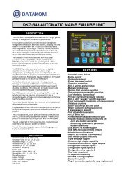
<strong>DKG</strong>-<strong>553</strong> <strong>MANUAL</strong> <strong>AND</strong> <strong>REMOTE</strong> <strong>START</strong> <strong>UNIT</strong><br />
DESCRIPTION<br />
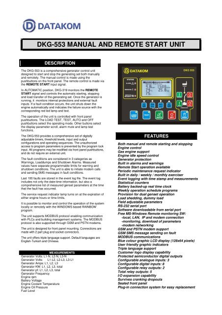
The <strong>DKG</strong>-<strong>553</strong> is a comprehensive generator control unit<br />
designed to start and stop the generating set both manually<br />
and remotely. The manual control is made using the<br />
pushbuttons on the front panel. The remote control is made via<br />
the <strong>REMOTE</strong> <strong>START</strong> input signal.<br />
In AUTOMATIC position, <strong>DKG</strong>-319 monitors the <strong>REMOTE</strong><br />
<strong>START</strong> signal and controls the automatic starting, stopping<br />
and load transfer of the generating set. Once the generator is<br />
running, it monitors internal protections and external fault<br />
inputs. If a fault condition occurs, the unit shuts down the<br />
engine automatically and indicates the failure source with the<br />
corresponding red led lamp and text.<br />
The operation of the unit is controlled with front panel<br />
pushbuttons. The LOAD TEST, TEST, AUTO and OFF<br />
pushbuttons select the operating mode. Other buttons select<br />
the display parameter scroll, alarm mute and lamp test<br />
functions.<br />
The <strong>DKG</strong>-<strong>553</strong> provides a comprehensive set of digitally<br />
adjustable timers, threshold levels, input and output<br />
configurations and operating sequences. The unauthorized<br />
access to program parameters is prevented by the program lock<br />
input. All programs may be modified via front panel pushbuttons,<br />
and do not require an external unit.<br />
The fault conditions are considered in 3 categories as<br />
Warnings, Loaddumps and Shutdown Alarms. Measured<br />
values have separate programmable limits for warning and<br />
shutdown conditions. The unit is able to initiate modem calls<br />
and sending SMS messages in fault conditions.<br />
Last 100 faults are stored in the event log file. The event log<br />
includes not only the date-time information, but also a<br />
comprehensive list of measured genset parameters at the time<br />
that the fault has occurred.<br />
The service request indicator lamp turns on at the expiration of<br />
either engine hours or time limits.<br />
It is possible to monitor and control the operation of the system<br />
locally or remotely with the WINDOWS based RAINBOW<br />
program.<br />
The unit supports MODBUS protocol enabling communication<br />
with PLCs and building management systems. The MODBUS<br />
protocol is also supported through GSM and PSTN modems.<br />
The unit is designed for front panel mounting. Connections are<br />
made with 2 part plug and socket connectors.<br />
The unit offers triple language support. Default languages are<br />
English-Turkish and Chinese.<br />
MEASUREMENTS<br />
Generator Volts: L1-N, L2-N, L3-N<br />
Generator Volts: L1-L2, L2-L3, L3-L1<br />
Generator Amps: L1, L2, L3<br />
Generator KW: L1, L2, L3, total<br />
Generator pf: L1, L2, L3, total<br />
Generator Frequency<br />
Engine rpm<br />
Battery Voltage<br />
Engine Coolant Temperature<br />
Engine Oil Pressure<br />
Fuel Level<br />
FEATURES<br />
Both manual and remote starting and stopping<br />
Engine control<br />
Gas engine support<br />
Engine idle speed control<br />
Generator protection<br />
Built in alarms and warnings<br />
Remote Start operation available<br />
Periodic maintenance request indicator<br />
Built in daily / weekly / monthly exerciser<br />
Event logging with time stamp and measurements<br />
Statistical counters<br />
Battery backed-up real time clock<br />
Weekly operation schedule programs<br />
Provision for dual genset operation<br />
Load shedding, dummy load<br />
Field adjustable parameters<br />
RS-232 serial port<br />
Software downloadable from serial port<br />
Free MS-Windows Remote monitoring SW:<br />
-local, LAN, IP and modem connection<br />
-monitoring, download of parameters<br />
-modem networking<br />
GSM and PSTN modem support<br />
GSM SMS message sending on fault<br />
MODBUS communications<br />
Blue colour graphic LCD display (128x64 pixels)<br />
User friendly graphic indicators<br />
Triple language support<br />
Customer logo display capability<br />
Protected semiconductor digital outputs<br />
Configurable analogue inputs: 3<br />
Configurable digital inputs: 8<br />
Configurable relay outputs: 2<br />
Total relay outputs: 5<br />
I/O expansion capability<br />
Survives cranking dropouts<br />
Sealed front panel<br />
Plug-in connection system for easy replacement
STATISTICS<br />
Following incremental counters provide statistics about past<br />
performance of the generating set:<br />
Engine Hours Run<br />
Total KW-h<br />
Engine Hours to Service<br />
Time to Service<br />
Number of Engine Cranks<br />
Number of Genset Runs<br />
EVENT LOGGING<br />
The <strong>DKG</strong>-<strong>553</strong> records last 100 events with date-time stamp<br />
and a total of 18 measured parameters. Recorded events are:<br />
-shutdown alarms, loaddumps and warnings<br />
-periodic records<br />
-generator status change<br />
WEEKLY OPERATION SCHEDULE<br />
In AUTO mode only, the unit offers the capability of defining a<br />
weekly operation schedule. Programmable parameters allow<br />
the genset to operate automatically only in defined time limits<br />
of each weekday.<br />
The internal battery backed-up real time clock allows precise<br />
switching times.<br />
DIGITAL INPUTS<br />
The unit has 8 configurable digital inputs. Each input has<br />
following programmable parameters:<br />
-alarm type: shutdown / warning / no alarm<br />
-alarm polling: on engine running / always / on mains OK<br />
-latching / non-latching operation,<br />
-contact type: NO / NC<br />
-switching: BAT+ / BAT-<br />
ANALOG INPUTS<br />
Engine analog inputs are provided for coolant temperature, oil<br />
pressure and fuel level. Analog inputs connect to resistive<br />
sender units to provide precise and adjustable protection. The<br />
inputs have programmable sensor characteristics so that they<br />
are suitable for any type and any brand of sensors.<br />
RELAY OUTPUTS<br />
The unit provides 5 relay outputs and 2 of them have<br />
programmable functions, selectable from a list. Any function or<br />
alarm condition may be output as a relay output.<br />
Using two Relay Expansion Modules, the number of relays<br />
may be increased to 21, 16 of them being volt-free contacts.<br />
TELEMETRY <strong>AND</strong> <strong>REMOTE</strong> PROGRAMMING<br />
The unit provides the user with large telemetry facilities via its<br />
standard RS-232 serial port, connecting either to a PC, PLC or<br />
a GSM or PSTN modem. It supports both RAINBOW and<br />
MODBUS communication protocols. The standard PC software<br />
offers local, Local Area Network (LAN), internet and modem<br />
operation capabilities as well as modem networking feature.<br />
The PC program is used for below purposes:<br />
-parameter upload/download<br />
-remote monitoring and control<br />
-diagnostics and analysis<br />
The MODBUS interface allows the unit to be integrated in<br />
building management systems.<br />
TECHNICAL SPECIFICATIONS<br />
Alternator voltage: 0 to 300 V-AC (Ph-N)<br />
Alternator frequency: 0-100 Hz.<br />
DC Supply Range: 9.0 to 30.0 V-DC<br />
Cranking dropouts: survives 0 V for 100ms.<br />
Typical Operating Current: 130 mA-DC<br />
DC Outputs: 1A @ 28V<br />
Charge excitation current: min 150mA @ 10 to 30 V-DC<br />
Current inputs: from CTs, .../5A. Max load 0.7VA per phase.<br />
Magnetic pickup input:: 1 – 30 Vac.<br />
Magnetic pickup frequency: 8KHz max.<br />
Analog input range: 0-5000 ohms.<br />
Serial port: RS-232, 2400 bauds, no parity, 1 bit stop<br />
Operating temp.: -20°C (-4°F) to 70 °C (158°F).<br />
Storage temp.: -30°C (-22°F) to 80 °C (176°F).<br />
Maximum humidity: 95% non-condensing.<br />
Dimensions: 202x148 x 48 mm (WxHxD)<br />
Panel Cut-out Dimensions: 183x134 mm minimum.<br />
Weight: 350 g (approx.)<br />
Case Material: High Temperature ABS/PC (UL94-V0)<br />
IP Protection: IP65 from front panel, IP30 from the rear<br />
Conformity (EU directives)<br />
-2006/95/EC (low voltage)<br />
-2004/108/EC (electro-magnetic compatibility)<br />
Norms of reference:<br />
EN 61010 (safety requirements)<br />
EN 61326 (EMC requirements)<br />
DATAKOM Electronics Ltd. http: www.datakom.com.tr<br />
Tel : +90-216-466 84 60 Fax : +90-216-364 65 65 e-mail : datakom@datakom.com.tr