

DKG-114-J - Piese schimb & Consumabile generatoare
DKG-114-J - Piese schimb & Consumabile generatoare
DKG-114-J - Piese schimb & Consumabile generatoare

Create successful ePaper yourself
Turn your PDF publications into a flip-book with our unique Google optimized e-Paper software.
<strong>DKG</strong>-<strong>114</strong>-J User Manual V-01 (15.04.2008)<br />
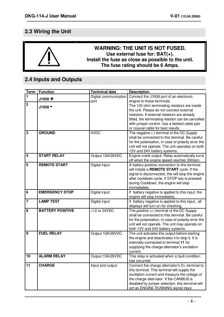
2.3 Wiring the Unit<br />
2.4 Inputs and Outputs<br />
WARNING: THE UNIT IS NOT FUSED.<br />
Use external fuse for: BAT(+).<br />
Install the fuse as close as possible to the unit.<br />
The fuse rating should be 6 Amps.<br />
Term Function Technical data Description<br />
1<br />
2<br />
J1939 +<br />
J1939 -<br />
Digital communication Connect the J1939 port of an electronic<br />
port<br />
engine to these terminals.<br />
The 120 ohm terminating resistors are inside<br />
the unit. Please do not connect external<br />
resistors. If external resistors are already<br />
fitted, the terminating resistor can be cancelled<br />
with jumper control. Use a twisted cable pair<br />
or coaxial cable for best results.<br />
3 GROUND 0VDC The negative (-) terminal of the DC Supply<br />
shall be connected to this terminal. Be careful<br />
for the polarization, in case of polarity error the<br />
unit will not operate. The unit operates on both<br />
12V and 24V battery systems.<br />
4 START RELAY Output 10A/28VDC Engine crank output. Relay automatically turns<br />
off when the engine speed reaches 300rpm.<br />
5 REMOTE START<br />
Digital input A battery positive connection to this terminal<br />
will initiate a REMOTE START cycle. If the<br />
signal is disconnected, this will stop the engine<br />
after cooldown cycle. If STOP key is pressed<br />
during Cooldown, the engine will stop<br />
immediately.<br />
6 EMERGENCY STOP Digital input If battery negative is applied to this input, the<br />
engine will stop immediately.<br />
7 LAMP TEST Digital input If battery negative is applied to this input, all<br />
displays will turn on for checking.<br />
8 BATTERY POSITIVE +12 or 24VDC The positive (+) terminal of the DC Supply<br />
shall be connected to this terminal. Be careful<br />
for the polarization, in case of polarity error the<br />
unit will not operate. The unit may operate on<br />
both 12V and 24V battery systems.<br />
9 FUEL RELAY Output 10A/28VDC The unit activates this output before starting<br />
the engine and deactivates it to stop it. It is<br />
internally connected to terminal 11 for<br />
supplying the charge alternator’s excitation<br />
current.<br />
10 ALARM RELAY Output 10A/28VDC This relay is activated when a fault condition<br />
has occurred.<br />
11 CHARGE Input and output Connect the charge alternator’s D+ terminal to<br />
this terminal. This terminal will supply the<br />
excitation current and measure the voltage of<br />
the charge alternator. If the CANBUS is<br />
disabled by jumper selection, this terminal will<br />
act as ENGINE RUNNING signal input.<br />
- 4 -