

DKG-114-J - Piese schimb & Consumabile generatoare
DKG-114-J - Piese schimb & Consumabile generatoare
DKG-114-J - Piese schimb & Consumabile generatoare

Create successful ePaper yourself
Turn your PDF publications into a flip-book with our unique Google optimized e-Paper software.
<strong>DKG</strong>-<strong>114</strong>-J User Manual V-01 (15.04.2008)<br />
Tel: +90-216-466 84 60<br />
Fax: +90-216 364 65 65<br />
datakom@datakom.com.tr<br />
http://www.datakom.com.tr<br />
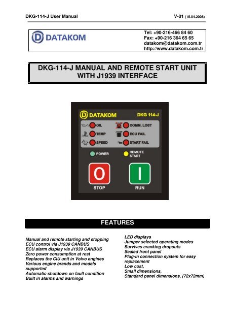
<strong>DKG</strong>-<strong>114</strong>-J MANUAL AND REMOTE START UNIT<br />
WITH J1939 INTERFACE<br />
Manual and remote starting and stopping<br />
ECU control via J1939 CANBUS<br />
ECU alarm display via J1939 CANBUS<br />
Zero power consumption at rest<br />
Replaces the CIU unit in Volvo engines<br />
Various engine brands and models<br />
supported<br />
Automatic shutdown on fault condition<br />
Built in alarms and warnings<br />
FEATURES<br />
LED displays<br />
Jumper selected operating modes<br />
Survives cranking dropouts<br />
Sealed front panel<br />
Plug-in connection system for easy<br />
replacement<br />
Low cost,<br />
Small dimensions,<br />
Standard panel dimensions, (72x72mm)
<strong>DKG</strong>-<strong>114</strong>-J User Manual V-01 (15.04.2008)<br />
TABLE OF CONTENTS<br />
Section<br />
1. DESCRIPTION<br />
2. INSTALLATION<br />
2.1. Introduction to the Control Panel<br />
2.2. Mounting the Unit<br />
2.3. Wiring the Unit<br />
2.4. Inputs and outputs<br />
3. DISPLAYS<br />
4. ALARMS<br />
5. MODES OF OPERATION<br />
6. J1939 ENGINE MONITORING AND CONTROL PORT<br />
7. JUMPER SELECTOR SWITCHES<br />
8. MAINTENANCE<br />
9. TROUBLESHOOTING<br />
10. DECLARATION OF CONFORMITY<br />
11. TECHNICAL SPECIFICATIONS<br />
12. CONNECTION DIAGRAM<br />
- 2 -
<strong>DKG</strong>-<strong>114</strong>-J User Manual V-01 (15.04.2008)<br />
1. DESCRIPTION<br />
The <strong>DKG</strong>-<strong>114</strong>-J is a low cost engine control unit designed to start and stop electronic engines both<br />
manually and remotely. The manual control is made using the pushbuttons on the front panel. The remote<br />
control is made via the REMOTE START input signal.<br />
The unit connects to ECU controlled electronic engines through its standard J1939 CANBUS port<br />
providing engine control and protection without extra senders. It has the ability of engine starting and<br />
stopping with J1939 messages. The ECU alarms are displayed with appropriate leds.<br />
The message starting feature allows removal of the CIU unit in message started engines.<br />
In the STOP position, the DC supply is removed from the module, thus zero power consumption<br />
is achieved.<br />
The unit powers up when the RUN button is pressed or BAT + is applied to the REMOTE START<br />
input. This will also energize the fuel solenoid relay. The engine is automatically started 3 times until<br />
operation.<br />
Once the engine is running, it monitors the ECU alarms. If a fault condition occurs, the unit shuts down<br />
the engine automatically and indicates the failure source with the corresponding red led lamp.<br />
If the STOP button is pressed or the REMOTE START signal removed, the engine will be stopped.<br />
The unit offers jumper selectable operating parameters, which lets it to be used with various engine brands<br />
and models.<br />
The unit fits into a standard 72x72mm panel meter opening and offers a very cost effective and space<br />
saving solution for the electronic engine control. Thanks to the completely sealed structure, IP65 protection<br />
degree is achieved from the front panel.<br />
The unit works on both 12 Volt and 24 Volt gensets.<br />
2. INSTALLATION<br />
2.1 Introduction to the Control Panel<br />
The control panel is designed to provide user friendliness for both the installer and the user.<br />
Jumper selectors allow the complete control over the generating set or engine.<br />
2.2 Mounting the Unit<br />
The unit is designed for panel mounting. The user should not be able to access parts of the unit other than<br />
the front panel.<br />
Mount the unit on a flat, vertical surface. The unit fits into a standard panel meter opening of 68x68 millimeters.<br />
Before mounting, remove the mounting brackets and connectors from the unit, then pass the unit through the<br />
mounting opening. The unit will be maintained in its position by the mounting brackets.<br />
Please use a twisted pair of cable or a dedicated 120 ohms coaxial cable for the CANBUS connection. The<br />
shield of the cable should be grounded at one end only.<br />
The charge alternator connection terminal provides also the excitation current, thus it is not necessary<br />
to use an external charge lamp.<br />
- 3 -
<strong>DKG</strong>-<strong>114</strong>-J User Manual V-01 (15.04.2008)<br />
2.3 Wiring the Unit<br />
2.4 Inputs and Outputs<br />
WARNING: THE UNIT IS NOT FUSED.<br />
Use external fuse for: BAT(+).<br />
Install the fuse as close as possible to the unit.<br />
The fuse rating should be 6 Amps.<br />
Term Function Technical data Description<br />
1<br />
2<br />
J1939 +<br />
J1939 -<br />
Digital communication Connect the J1939 port of an electronic<br />
port<br />
engine to these terminals.<br />
The 120 ohm terminating resistors are inside<br />
the unit. Please do not connect external<br />
resistors. If external resistors are already<br />
fitted, the terminating resistor can be cancelled<br />
with jumper control. Use a twisted cable pair<br />
or coaxial cable for best results.<br />
3 GROUND 0VDC The negative (-) terminal of the DC Supply<br />
shall be connected to this terminal. Be careful<br />
for the polarization, in case of polarity error the<br />
unit will not operate. The unit operates on both<br />
12V and 24V battery systems.<br />
4 START RELAY Output 10A/28VDC Engine crank output. Relay automatically turns<br />
off when the engine speed reaches 300rpm.<br />
5 REMOTE START<br />
Digital input A battery positive connection to this terminal<br />
will initiate a REMOTE START cycle. If the<br />
signal is disconnected, this will stop the engine<br />
after cooldown cycle. If STOP key is pressed<br />
during Cooldown, the engine will stop<br />
immediately.<br />
6 EMERGENCY STOP Digital input If battery negative is applied to this input, the<br />
engine will stop immediately.<br />
7 LAMP TEST Digital input If battery negative is applied to this input, all<br />
displays will turn on for checking.<br />
8 BATTERY POSITIVE +12 or 24VDC The positive (+) terminal of the DC Supply<br />
shall be connected to this terminal. Be careful<br />
for the polarization, in case of polarity error the<br />
unit will not operate. The unit may operate on<br />
both 12V and 24V battery systems.<br />
9 FUEL RELAY Output 10A/28VDC The unit activates this output before starting<br />
the engine and deactivates it to stop it. It is<br />
internally connected to terminal 11 for<br />
supplying the charge alternator’s excitation<br />
current.<br />
10 ALARM RELAY Output 10A/28VDC This relay is activated when a fault condition<br />
has occurred.<br />
11 CHARGE Input and output Connect the charge alternator’s D+ terminal to<br />
this terminal. This terminal will supply the<br />
excitation current and measure the voltage of<br />
the charge alternator. If the CANBUS is<br />
disabled by jumper selection, this terminal will<br />
act as ENGINE RUNNING signal input.<br />
- 4 -
<strong>DKG</strong>-<strong>114</strong>-J User Manual V-01 (15.04.2008)<br />
3. DISPLAYS<br />
POWER: (green) it flashes when the unit is powered on. It turns steadily on when the engine is running.<br />
REMOTE START: (yellow) it turns on when the remote start signal is present.<br />
4. ALARMS<br />
Alarms indicate an abnormal situation in the engine and cause:<br />
- The related alarm led to turn on steadily,<br />
- The engine to stop immediately,<br />
- The Alarm relay output to operate,<br />
- The related alarm source led to flash.<br />
Alarm LEDs will stay on and disable the operation of the engine even if the alarm source is removed. In<br />
order to reset the alarm conditions press the STOP button.<br />
COMMUNICATION LOST: Set if no information has been received during 3 seconds from the ECU of the<br />
electronic engine. This fault condition is only controlled when the fuel is on.<br />
ECU FAIL: Set when an engine fault code is received from the ECU of the electronic engine. The alarm<br />
source will also be indicated by flashing OIL, TEMP and SPEED leds wherever applicable.<br />
OIL: Flashes if a fault code concerning the oil pressure is received from the ECU of the electronic engine.<br />
TEMP: Flashes if a fault code concerning the coolant temperature is received from the ECU of the electronic<br />
engine.<br />
SPEED: Flashes if a fault code concerning the engine rpm is received from the ECU of the electronic engine.<br />
5. MODES OF OPERATION<br />
The modes of operation are selected by pressing the front panel keys.<br />
MANUAL START / REMOTE START: Manual start mode is entered by pressing the front panel RUN key,<br />
remote start mode is entered by applying the battery positive voltage to the REMOTE START terminal.<br />
In both modes, the engine will be started 3 times. When the engine runs, the crank relay will be immediately<br />
deactivated.<br />
MANUAL STOP / REMOTE STOP: Manual stop mode is entered by pressing the front panel STOP key,<br />
remote stop mode is entered by disconnecting the battery positive voltage from the REMOTE START terminal.<br />
When engine stop is requested, a cooldown cycle of 30 seconds will be entered. At the end of the cooldown<br />
cycle the engine will stop. If immediate stop is requested, the STOP key should be pressed again.<br />
If no alarm exists, the unit disconnects from the power source in order to reach zero power consumption. If<br />
alarm exists, the unit will not power off until the front panel STOP key is pressed.<br />
- 5 -
<strong>DKG</strong>-<strong>114</strong>-J User Manual V-01 (15.04.2008)<br />
6. J1939 ENGINE MONITORING AND CONTROL PORT<br />
The unit offers a special J1939 port in order to communicate with electronic engines controlled by<br />
an ECU (electronic control unit).<br />
The J1939 port consists of 2 terminals which are J1939+ and J1939-. The connection between the<br />
unit and the engine should be made with either a twisted cable pair or a coaxial cable. If a coaxial cable is<br />
used, the external conductor should be grounded at one end only.<br />
The 120 ohms termination resistor is included inside the unit with jumper control. Please do not<br />
connect external resistor. If the terminating resistor is already installed, the internal 120 ohms resistor may<br />
be cancelled by removing JP1.<br />
The J1939 port is activated by inserting the jumper JP2.<br />
If the engine is a message started type like Volvo models insert also jumper JP3.<br />
Please contact DATAKOM for the current list of supported engines.<br />
When the fuel output is active, if no information is received from the ECU during last 3 seconds,<br />
then the unit will give a COMMUNICATION LOST alarm and stop the engine. This feature prevents<br />
uncontrolled engine operation.<br />
Any fault condition received from the ECU of the electronic engine will also cause the engine to be<br />
stopped. If the fault condition is caused by the oil pressure sensor, coolant temperature sensor or engine<br />
speed sensor the related alarm led will also flash.<br />
7. JUMPER SELECTOR SWITCHES<br />
FUNCTION JUMPERS SETTINGS<br />
Terminating resistor JP1<br />
CANBUS enable JP2<br />
Message start JP3<br />
8. MAINTENANCE<br />
ON: 120 ohms Terminating resistor is inserted<br />
OFF: No terminating resistor<br />
ON: CANBUS communication enabled<br />
OFF: CANBUS communication disabled<br />
ON: Message started engine (some Volvo types)<br />
OFF: Crank relay started engine (most common engine type)<br />
DO NOT OPEN THE UNIT<br />
There are NO serviceable parts inside the unit.<br />
Wipe the unit, if necessary with a soft damp cloth. Do not use chemical agents<br />
- 6 -
<strong>DKG</strong>-<strong>114</strong>-J User Manual V-01 (15.04.2008)<br />
9. TROUBLESHOOTING<br />
When the RUN key is pressed the unit gives COMMUNICATION LOST alarm:<br />
- Check that CANBUS J1939 cables are connected properly to the ECU.<br />
- Check the terminating resistor necessity and set jumper JP1 accordingly.<br />
- Check polarity reversal of the cables.<br />
- Connect the ground terminal of the unit to the ground terminal of the ECU.<br />
- Use coaxial cable, ground at one end.<br />
- Check sanity of the ECU.<br />
When the engine is running the unit gives COMMUNICATION LOST alarm:<br />
- Excessive EMI noise:<br />
- Connect the ground terminal of the unit to the ground terminal of the ECU.<br />
- Use coaxial cable, ground at one end.<br />
- Check the terminating resistor necessity and set jumper JP1 accordingly.<br />
10. DECLARATION OF CONFORMITY<br />
The unit conforms to the EU directives<br />
-2006/95/EC (low voltage)<br />
-2004/108/EC (electro-magnetic compatibility)<br />
Norms of reference:<br />
EN 61010 (safety requirements)<br />
EN 61326 (EMC requirements)<br />
The CE mark indicates that this product complies with the European requirements for safety, health<br />
environmental and customer protection.<br />
- 7 -
<strong>DKG</strong>-<strong>114</strong>-J User Manual V-01 (15.04.2008)<br />
11. TECHNICAL SPECIFICATIONS<br />
DC Supply Range: 9.0 to 30.0 V-DC<br />
Cranking dropouts: survives 0 V for 100ms.<br />
Typical Standby Current: 0 mA-DC in OFF mode.<br />
Maximum Operating Current: 250 mA-DC (Relay outputs open)<br />
DC Relay Outputs: 10 A / 28V-DC<br />
Charge excitation current: 150mA-min @ 10 to 30V-DC<br />
Digital inputs: input voltage 0 - 30 VDC. Internally connected to battery positive via 4700 ohm resistor.<br />
Number of starts: 3<br />
Start duration: 8 sec.<br />
Wait between starts: 10 sec.<br />
Cooldown: 30 sec.<br />
Alarm duration: 1 minute.<br />
Protection delay: 8 sec.<br />
Operating temp.: -20°C (-4°F) to 70 °C (158°F).<br />
Storage temp.: -40°C (-40°F) to 80 °C (176°F).<br />
Humidity: max 95% (non-condensing)<br />
Dimensions: 72 x 72 x 43 mm (WxHxD)<br />
Panel Cut-out Dimensions: 69 x 69 mm minimum.<br />
Measurement category: CAT II<br />
Air category: Pollution degree II<br />
Weight: 180 g (approx.)<br />
Case Material: High Temp. ABS (UL94-V0, 100°C)<br />
IP Protection: front panel:IP65, rear: IP30<br />
Case material: High temperature, self extinguishing ABS (UL94-V0, 100 °C)<br />
12. CONNECTION DIAGRAM<br />
- 8 -