LABTOOL-848XP - Advantech Equipment Corp.
LABTOOL-848XP - Advantech Equipment Corp.
LABTOOL-848XP - Advantech Equipment Corp.

Create successful ePaper yourself
Turn your PDF publications into a flip-book with our unique Google optimized e-Paper software.
<strong>LABTOOL</strong>-<strong>848XP</strong><br />
Turbo Gang Programmer<br />
User's Manual<br />
2006/11/02 Revision A0.4
Copyright Notice<br />
This document is copyrighted, 1998-2006 by <strong>Advantech</strong> <strong>Equipment</strong> <strong>Corp</strong>.. All rights are reserved.<br />
<strong>Advantech</strong> <strong>Equipment</strong> <strong>Corp</strong>., reserves the right to make improvements to the products described in<br />
this manual at any time without notice.<br />
No part of this manual may be reproduced, copied, translated or transmitted in any form or by any<br />
means without the prior written permission of <strong>Advantech</strong> <strong>Equipment</strong> <strong>Corp</strong>. Information provided in<br />
this manual is intended to be accurate and reliable. However, <strong>Advantech</strong> <strong>Equipment</strong> <strong>Corp</strong>. assumes<br />
no responsibility for its use nor for any infringements upon the rights of third parties which may<br />
result from its use.<br />
Acknowledgments<br />
IBM, PC AT and VGA are trademarks of International Business Machines <strong>Corp</strong>oration.<br />
MS-Windows are trademarks of Microsoft <strong>Corp</strong>oration.<br />
2
How to use this manual<br />
Thank you for purchasing the <strong>LABTOOL</strong>-<strong>848XP</strong> Turbo Gang Programmer. We designed this<br />
manual to help you quickly and easily set up and use your <strong>LABTOOL</strong>-<strong>848XP</strong>. You can use the<br />
manual in two ways:<br />
Step by step:<br />
The manual should be used in conjunction with the On-line help contained in the <strong>LABTOOL</strong>-<br />
<strong>848XP</strong> software. Once you've installed the <strong>LABTOOL</strong>-<strong>848XP</strong> and the software, you shouldn't need<br />
this manual again. You can just press 'F1' in the program and context sensitive help will guide you<br />
through the processes.<br />
Quick Start:<br />
Our special Quick Start section gives experienced users the information they need to setup the<br />
<strong>LABTOOL</strong>-<strong>848XP</strong> and software, and basic guidelines on using the <strong>LABTOOL</strong>-<strong>848XP</strong>. If you need<br />
more information, you can refer to the rest of the manual. If you have any problems, you can work<br />
through the manual step by step for easy troubleshooting.<br />
If you have any questions, feel free to call your local distributor or sales representative.<br />
Software update:<br />
Please visit our website at www.aec.com.tw to update the software.<br />
3
Packing list<br />
Before you begin installing your <strong>LABTOOL</strong>-<strong>848XP</strong>, please make sure that the following materials<br />
have been shipped:<br />
• 1 <strong>LABTOOL</strong>-<strong>848XP</strong> turbo gang programmer<br />
• 1 Power cord<br />
• 1 parallel cable<br />
• 1 USB cable<br />
• 1 CD-ROM containing the Windows software<br />
4
Contents<br />
Chapter 0 Quick Start...................................................................7<br />
Quick Start ................................................................................8<br />
Chapter 1 General Information....................................................9<br />
Introduction.............................................................................10<br />
Features...................................................................................10<br />
Using the <strong>LABTOOL</strong>-<strong>848XP</strong> Software..................................12<br />
Chapter 2 Installation .................................................................14<br />
Minimum PC System Requirements.......................................15<br />
Installing the <strong>LABTOOL</strong>-<strong>848XP</strong> Software ............................15<br />
Installing the <strong>LABTOOL</strong>-<strong>848XP</strong> ..........................................15<br />
Upgrading the <strong>LABTOOL</strong>-<strong>848XP</strong> Software ..........................15<br />
Chapter 3 Command Hierarchy.................................................16<br />
<strong>LABTOOL</strong>-<strong>848XP</strong> Command Hierarchy...............................17<br />
Chapter 4 Operation ...................................................................18<br />
LED Display on Each Socket ...............................................19<br />
LED color key.........................................................................19<br />
File Commands .....................................................................19<br />
Save Buffer .............................................................................19<br />
Load File.................................................................................20<br />
Exit to Window.......................................................................21<br />
Project Commands ...............................................................21<br />
Save Project ........................................................................21<br />
Load Project ........................................................................21<br />
Device Commands.................................................................22<br />
Change Device ....................................................................22<br />
Mass-production Mode ……………………………………...23<br />
Editing the Buffer ..................................................................24<br />
Blank Checking a device .......................................................25<br />
Reading a device ....................................................................25<br />
Programming a device ............................................................25<br />
Verifying a device...................................................................26<br />
Memory Protect ......................................................................27<br />
Erasing a device ......................................................................27<br />
Configuration..........................................................................27<br />
Options...................................................................................28<br />
Modify Algorithm Parameters ................................................28<br />
Device operation options ........................................................29<br />
Module options .......................................................................31<br />
Parallel Port.............................................................................32<br />
Statistic Option .......................................................................33<br />
Diagnostics.............................................................................34<br />
Self Test ..................................................................................35<br />
Chapter 5 Using Adapters .........................................................36<br />
Adapter requirements..............................................................37<br />
5
Appendix A Error Messages......................................................40<br />
Error Messages .......................................................................41<br />
Appendix B USB Software General Information .....................43<br />
Feature ....................................................................................44<br />
Installing <strong>LABTOOL</strong>-<strong>848XP</strong> USB software..........................44<br />
Multiple Programmers Operation ...........................................45<br />
6
CHAPTER<br />
Quick Start<br />
0<br />
7
Quick Start<br />
0-1) This CD-ROM only has <strong>LABTOOL</strong>-<strong>848XP</strong>‘s parallel port software.<br />
0-2) The parallel port must be EPP mode or ECP mode or BPP mode, the EPP mode is<br />
recommended.<br />
0-3) You could download the USB software “β version” from our website: www.aec.com.tw<br />
1) The <strong>LABTOOL</strong>-<strong>848XP</strong> must be turned off before you install its software.<br />
2) Install <strong>LABTOOL</strong>-<strong>848XP</strong>’s software then restart your PC or notebook.<br />
3) Turn on your <strong>LABTOOL</strong>-<strong>848XP</strong> and run its software.<br />
4) Select the chip type to be programmed first.<br />
Use the Hot key “ALT-C”, then type the complete part number of the chips to be programmed;<br />
or use the mouse to select the correct part number.<br />
5) Load the design file into the buffer.<br />
Use the Hot key “ALT-L”, then specify the origin of the file and load.<br />
6) Alternatively, you can read a master chip into the buffer instead of a design file.<br />
The default master socket is socket 0. By putting a chip into socket 0 and performing the Read<br />
operation (Hot key ALT-R), you can transfer the chip’s contents into the buffer.<br />
You can also select any socket as the master socket. Go to the main menu, select the module<br />
options (Hot key F5), then set the master socket, insert a master chip into the master socket, and<br />
perform Read.<br />
7) Insert 8 chips of the same type into the 8 ZIF sockets, set the device operation option (Hot key<br />
F4), then perform Program (Hot key ALT-P). You can now program the 8 chips simultaneously.<br />
8) To speed up throughput, a user can change the mode to Mass production mode (Hot Key Alt-M).<br />
After entering this mode, the <strong>LABTOOL</strong>-<strong>848XP</strong> will program chips automatically after they are<br />
properly inserted into the socket. <strong>LABTOOL</strong>-<strong>848XP</strong> has both a standard mass production mode<br />
and a concurrent mass production mode. Standard mode allows the <strong>LABTOOL</strong>-<strong>848XP</strong> to<br />
program 8 devices at the same time. Concurrent mode divides the 8 sockets into two groups,<br />
group 1 comprised of sockets 0-3 and group 2 comprised of sockets 4-7. Chips in group 1 can be<br />
programmed while chips are inserted or unloaded in group2. After the programming of chips in<br />
group1 is finished, <strong>LABTOOL</strong>-<strong>848XP</strong> automatically programs the chips in group2.<br />
A user can enable the insertion timer and adjust the timer. Enabling the timer will allow<br />
<strong>LABTOOL</strong>-<strong>848XP</strong> to automatically shutdown a poor contact socket upon timeout of a user-set<br />
timer period. <strong>LABTOOL</strong>-<strong>848XP</strong> then automatically programs the chips in the remaining good<br />
sockets. The insertion timer default setting is 5 seconds. When the insertion timer is disabled,<br />
the user will have to either correct the insertion error or press the ignore key to continue<br />
programming after a poor contact socket is discovered.<br />
9) <strong>LABTOOL</strong>-<strong>848XP</strong> also automatically keeps a running total of all chips that have been through<br />
programming and all chips encountering programming failures. A user can input a target<br />
quantity of chips to be programmed and an allowable number of programming failures. An<br />
alarm message option provides a message to the screen alerting the user to either the target<br />
quantity of chips being reached, or the allowable number of failures being reached.<br />
10) For a detailed explanation of the device operation options, please refer to Chapters 3 and 4.<br />
8
CHAPTER<br />
General Information<br />
1<br />
9
Introduction<br />
The <strong>LABTOOL</strong>-<strong>848XP</strong> is a PC-based gang programmer that works through your PC's parallel port.<br />
It features eight fully isolated 48-pin ZIF sockets, extremely high throughput, standard 5 V and 3 V<br />
chip support, production piece counts, and device insertion and continuity checks, all within a<br />
PC-based design. Device updates are disseminated through software, giving our customers quicker<br />
and more flexible access to new chip support. <strong>LABTOOL</strong>-<strong>848XP</strong> future software updates in<br />
EPROM, EEPROM, and FLASH technology will include 87C5x, 89C5x, and PIC16Cxx<br />
microprocessor support. The <strong>LABTOOL</strong>-<strong>848XP</strong> was designed with flexibility in mind. If a<br />
customer has special chips that are not in our standard support list, we can provide special programs<br />
which will allow the <strong>LABTOOL</strong>-<strong>848XP</strong> to perform as a customized special production gang<br />
programmer.<br />
Features<br />
Universal adapter for Flash chips<br />
The <strong>LABTOOL</strong>-<strong>848XP</strong> is designed to meet your future needs in high density Flash chips. Using the<br />
resources of your PC, it supports 32 K bit up to 256 M bit memory chips without upgrading its<br />
hardware. The <strong>LABTOOL</strong>-<strong>848XP</strong> also has a universal adaptor which accommodates 48-pin TSOP,<br />
44-pin PSOP, 40-pin TSOP, and 32-pin TSOP Flash chips, which eliminates the need to buy<br />
multiple adapters and saves you money.<br />
Unbeatable speed through semi-concurrent programming technology<br />
The <strong>LABTOOL</strong>-<strong>848XP</strong>'s on-board intelligence reduces system overhead to a minimum. It can<br />
program eight Flash chips of 8 MB capacity (such as Intel 28F800B3, for example) within 45<br />
seconds. An experienced programmer can program thousands of high-density chips per day.<br />
Furthermore, the <strong>LABTOOL</strong>-<strong>848XP</strong> supports two programming modes. In standard programming<br />
mode, the <strong>LABTOOL</strong>-<strong>848XP</strong> automatically programs all eight chips after all eight pieces have been<br />
inserted into the sockets. In semi-concurrent programming mode, a user can divide the 8 sockets into<br />
two groups (of 4 sockets each). By using the technique of programming 4 chips while<br />
simultaneously removing and inserting the other 4 chips, a customer can increase throughput. This<br />
also allows interface with the fine pitch pick and place handler for high-density fine pitch chips.<br />
Statistic Functions<br />
The <strong>LABTOOL</strong>-<strong>848XP</strong> automatically keeps a running total of all production pieces attempted and<br />
all production pieces failed. Users can input a target quantity of chips to be programmed and an<br />
allowable number of failures. An alarm function can be enabled to send a message to the screen<br />
alerting the user to either the target quantity of chips being reached, or the allowable number of<br />
failures being reached.<br />
Fully isolated ZIF sockets<br />
The <strong>LABTOOL</strong>-<strong>848XP</strong> has fully isolated (> 1 M ohms) circuits for each socket's address/data<br />
bus/control lines. Each socket has its own built-in Vcc and Vpp current-limiting circuitry. A<br />
defective device in one socket will not affect the devices in or programming integrity of the<br />
remaining sockets.<br />
Device-insertion and continuity checks - No mistakes!<br />
The <strong>LABTOOL</strong>-<strong>848XP</strong> performs device-insertion and continuity checks before programming each<br />
device. It can detect poor pin contact, upside-down device insertion, incorrect position, and pin<br />
number mismatch. This function protects your pocketbook by preventing expensive chip damage<br />
caused by operator error.<br />
Auto-sensing and self-programming<br />
The <strong>LABTOOL</strong>-<strong>848XP</strong> has implemented patented technology to meet mass-production<br />
requirements. When a chip fails the device insertion check, the <strong>LABTOOL</strong>-<strong>848XP</strong> waits for an<br />
10
operator adjustable time. If the operator fails to correct the improper insertion within the selected<br />
time period, the socket with the improper insertion is shutdown and the other chips are automatically<br />
programmed.<br />
Independent module design<br />
The <strong>LABTOOL</strong>-<strong>848XP</strong> is designed to achieve a minimum of down time. Its 8 sockets are divided<br />
into 4 identical modules having two sockets each. Each module is independent of the other three<br />
modules. If one module fails, the customer can continue to operate the other three modules without<br />
sacrificing the turnaround time to repair. Extra modules are available to customers in spare kits.<br />
Project file "Save and Load"<br />
You can save the program configuration project file which contains the device selection, the buffer<br />
data and all of the program setup options. This file can be recalled at any time for future use without<br />
having to go through the setup procedure again. This allows you to pass your design file to the<br />
production department without mistakes. You can also read the data from a device into the buffer<br />
from any of the 8 sockets, according to your specification.<br />
Variable V CC with one or two-pass verification<br />
The <strong>LABTOOL</strong>-<strong>848XP</strong> allows users to select the verification voltage after chip programming is<br />
completed, e.g., V CC +/- 5%, V CC +/- 10%. V CC can range from 2 V to 7.5 V. Verification<br />
ensures that the chips have been properly programmed, with no data retention problems.<br />
<strong>LABTOOL</strong>-<strong>848XP</strong> Diagram<br />
11
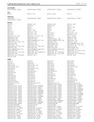
Device support summary<br />
General EPROM: 27xxx series 32 K to 32 Mb with 8/16 bit data width.<br />
Flash EPROM: supports NOR, NAND, AND, DI-NOR, and EEPROM technology<br />
29xxx, 5 V / 3 V Flash, 28Fxxx 12 V / 5 V / 3 V Flash from all major chip vendors.<br />
Microprocessor: (Future release through software update)<br />
Intel 87C5x compatible, ATMEL 89C5x compatible, Micro chip PIC16Cxx.<br />
Specification:<br />
Socket and pin driver:<br />
8 fully isolated 48 pin ZIF sockets with receptacle, over 1 M ohm resistance between each socket.<br />
Four DACs for VCC , VPP1 , VPP2 and VPP3 with 8 bit resolution.<br />
V CC range 2 V to 7.5 V, resolution 50 mV<br />
V PP1, 2 & 3 range 5 V to 16 V, resolution 100 mV<br />
Overcurrent protection on all voltage sources<br />
Logic level 5 V to 2.7 V programmable by software<br />
Device Operation: Read, blank check, insertion/contact check, verify, check sum, erase chip,<br />
program, memory protect, edit buffer, configuration, load file, save file, project file load/save<br />
File format: Binary, Intel HEX, Intel extend HEX, Motorola S, HP64000ABS, TEK HEX, straight<br />
Hex<br />
General<br />
Power: 100 V AC to 240 V AC , 47-63 Hz auto switch<br />
Power consumption: 65 W<br />
Operation temperature: 5 to 45 °C (41 to 113 °F)<br />
Safety: CE & LVD certified<br />
Weight: 8.5 kg net, 10 kg shipping weight<br />
Using the <strong>LABTOOL</strong>-<strong>848XP</strong> Software<br />
Menus<br />
Accessing the menus can be done in two ways:<br />
Use the mouse and click on the menu option displayed at the top of the screen. A pull-down menu<br />
will appear, and you can select the option you desire by clicking on that option.<br />
If you do not have a mouse available, you can also use the keyboard to access the menus. Press<br />
[F10] to activate the main menu bar.<br />
Select the sub-menu that you want to use with the left and right arrow keys, and press to<br />
activate the sub-menu. Use the up and down arrows to select an option to execute. Press <br />
to execute the command.<br />
Hot-keys<br />
Most of the options available on the menus can also be executed by pressing the hot-key associated<br />
with that option. To see what the hot-key is for a certain option, look on the menu where the option<br />
is located. If a hot-key is available, it will be displayed next to the option name.<br />
12
Hot Keys<br />
Main Menu<br />
Sub Menu<br />
Device Information<br />
Information Line<br />
Statistics<br />
13
CHAPTER<br />
Installation<br />
2<br />
14
Minimum PC System Requirements<br />
O.S.: (1) Parallel port: Win 95/98/ME, Win 2000, Win XP, Win NT 4.0 or latest<br />
(NT OS system, need NT System ADM).<br />
(2) USB port: Win 98/ME, Win 2000 SP4, Win XP SP1/SP2 or latest.<br />
CPU: PII 750 and above<br />
RAM: 64 MB minimum, 128 MB recommended<br />
HD: 16 MB of free hard disk space.<br />
Interfaces: (1) D-25 connector with parallel port EPP or ECP or BPP mode, EPP mode is<br />
recommended<br />
(2) USB 1.1/2.0, USB2.0 is recommended<br />
Installing the <strong>LABTOOL</strong>-<strong>848XP</strong> Software<br />
Insert the CD into the PC's CD-ROM E: Drive.<br />
In the file manager, you can select the E:\Setup and hit Enter; it will create a directory called<br />
WLT<strong>848XP</strong> on your computer's C:\Programm Files\AEC\WL<strong>848XP</strong> path and will install the<br />
<strong>LABTOOL</strong>-<strong>848XP</strong> software in this directory.<br />
Following successful installation, restart your PC then run the software.<br />
Installing the <strong>LABTOOL</strong>-<strong>848XP</strong><br />
1. Switch the PC and the <strong>LABTOOL</strong>-<strong>848XP</strong> off.<br />
2. Connect the <strong>LABTOOL</strong>-<strong>848XP</strong> to a parallel port using the cable supplied.<br />
3. Switch the PC on.<br />
4. Switch the <strong>LABTOOL</strong>-<strong>848XP</strong> on.<br />
Upgrading the <strong>LABTOOL</strong>-<strong>848XP</strong> Software<br />
We provide quarterly formal releases of the <strong>LABTOOL</strong>-<strong>848XP</strong> software on our website. Monthly<br />
temporary releases are also available on our website. Please download releases from our website at:<br />
www.aec.com.tw<br />
15
CHAPTER<br />
Command Hierarchy<br />
3<br />
16
<strong>LABTOOL</strong>-<strong>848XP</strong> Command Hierarchy<br />
File (Alt+F) Save Buffer Alt+S<br />
Load File Alt+L<br />
Exit Alt+X<br />
Project (Alt+J) Save Project Alt+F1<br />
Load Project Alt+F2<br />
Device (Alt+D) Change Alt+C<br />
Mass Production Mode Alt+M<br />
Edit Alt+E<br />
Read Alt+R<br />
Blank Check Alt+B<br />
Program Alt+P<br />
Verify Alt+V<br />
Memory Prot/Prog Config Alt+Y<br />
Erase Alt+K<br />
Configuration Alt+U<br />
Options (Alt+O) Parameters F3<br />
Operation F4<br />
Module Options F5<br />
Parallel Port F6<br />
Statistic F7<br />
Diagnostics (Alt+I) Self Test F8<br />
17
CHAPTER<br />
Operation<br />
4<br />
18
LED Display on Each Socket<br />
Each of the 8 sockets in the <strong>LABTOOL</strong>-<strong>848XP</strong> has a three-color LED display to indicate the status<br />
of the socket. Read this section carefully to avoid damage to chips.<br />
Warning: Do not insert or remove a chip from a socket while the socket LED is<br />
yellow!<br />
LED color key<br />
Blank the socket is not active.<br />
Green the socket is active or the last operation result passed<br />
Yellow the socket is busy; don’t do anything until the LED turns Green or Red.<br />
Red the last operation resulted in failure; the socket is active and awaiting another operation.<br />
Flashing LED, 5 Hz frequency. This mode only applies to insertion and contact checks of the<br />
chips in the socket.<br />
Flashing Green the chip passed the continuity check.<br />
Flashing Yellow the socket is active and waiting for a chip to be inserted.<br />
Flashing Red the chip failed the insertion/continuity check, due to poor contact, incorrect chip<br />
positioning, pin count mismatch, chip upside-down, pin short-circuit, or chip<br />
damage.<br />
File Commands<br />
Save Buffer<br />
Menu File | Save Buffer<br />
Hot-key Alt+S<br />
This option is used to save the memory buffer to a file on the hard disk.<br />
Select a file (to overwrite!) using the mouse, or type the file name in the box provided. You can also<br />
type in a file spec. (e.g. *.hex) at the Name prompt. This will display all the files of the specified<br />
type, and you can then select the required file to overwrite.<br />
ViewText<br />
Certain file types contain header information. Click on this box to see this information. This will<br />
display information similar to the following:<br />
ABEL(tm) 3.00a FutureNet Div, Data I/O <strong>Corp</strong>. JEDEC file for: P16V8R<br />
Created on: 15-Sep-04 04:17 PM<br />
PROM8908 pin configuration Ver 3.0<br />
AEC Programmers 4 NOV 2004*<br />
QP20* QF2194*<br />
L0000<br />
01101111111111111111111111111111<br />
00000000000000000000000000000000<br />
Output File Format<br />
Select the file format of the output file.<br />
19
From Buffer Mode<br />
This mode functions as follows:<br />
Normal<br />
Every byte is written to the output file.<br />
File shuffling<br />
Odd<br />
Every Odd byte is written to the output file.<br />
Even<br />
Every Even byte is written to the output file.<br />
The following four options are used to write the buffer into four different files:<br />
1st byte of 4<br />
This writes the bytes 1, 5, 9, 13, ... into the output file.<br />
2nd byte of 4<br />
This writes the bytes 2, 6, 10, 14, ... into the output file.<br />
3rd byte of 4<br />
This writes the bytes 3, 7, 11, 15, ... into the output file.<br />
4th byte of 4<br />
This writes the bytes 4, 8, 12, 16, ... into the output file.<br />
Load File<br />
Menu File | Load File<br />
Hot-key Alt+L<br />
This option loads a file from disk into the memory buffer. The type of files that can be loaded for a<br />
device depends on the device type.<br />
Select a file to load using the mouse, or type the filename in the box provided. You can also type in<br />
a file spec. (e.g. *.hex) at the Name prompt. This will display all the files of the specified type, and<br />
you can then select the required file to load.<br />
ViewText<br />
Certain file types contain header information. Click on this box to see this information. This will<br />
display information similar to the following:<br />
ABEL(tm) 3.00a FutureNet Div, Data I/O <strong>Corp</strong>. JEDEC file for: P16V8R<br />
Created on: 15-Sep-04 04:17 PM<br />
PROM8908 pin configuration Ver 3.0<br />
AEC Programmers 4 NOV 2004*<br />
QP20* QF2194*<br />
L0000<br />
01101111111111111111111111111111<br />
00000000000000000000000000000000<br />
Auto Format Detected<br />
The software automatically detects the format of the file that is to be loaded. If the desired format of<br />
the file differs from the format detected, select the correct file format.<br />
From File Mode<br />
This option indicates which bytes must be read in the input file. Select the required format.<br />
To Buffer Mode<br />
This option indicates where the byte previously read is to be written. This enables you to 'build' the<br />
memory buffer from several files.<br />
20
From File Address<br />
If only a selected range is to be read from the input file, fill in the address that will contain the first<br />
byte into this box, and the size of the buffer to be read in Size.<br />
To Buffer Address<br />
If the data read is to be copied into a specific area of the buffer, fill in the starting address here.<br />
Size<br />
This box contains the buffer size. By default it is the same size as the device size. If you want to<br />
download a file into memory that is bigger than the active device, insert the size here (or in Options |<br />
Operation Options).<br />
Clear Buffer Options<br />
Four options are available during memory buffer data loading. The default option is to clear the<br />
buffer to its blank state prior to data loading.<br />
Disable<br />
This option leaves the original buffer data unchanged, but then overwrites it with the contents of the<br />
newly loaded file.<br />
Blank state<br />
This option clears the buffer to the device blank state (using command 00 or FF, depending on<br />
device selection), then overwrites the buffer during file loading.<br />
0x00<br />
First clears the buffer of its contents using command 00, then overwrites the buffer with the new file<br />
contents<br />
0xFF<br />
First clears the buffer of its contents using command FF, then overwrites the buffer with the new file<br />
contents.<br />
Exit to Window<br />
Menu File | Exit to Window<br />
Hot-key Alt+X<br />
Quit the <strong>LABTOOL</strong>-<strong>848XP</strong> program and exit.<br />
Project Commands<br />
Save Project<br />
Menu Project | Save Project<br />
Hot-key Alt+F1<br />
This option saves the current setup of the <strong>LABTOOL</strong>-<strong>848XP</strong> software into a project file. The file<br />
includes devices selected, buffer data, operation options setup and device configuration setup. You<br />
can also attach a footnote to this project file. The project file acts as a macro, eliminating the need to<br />
go through each procedure during future programming sessions.<br />
Load Project<br />
Menu Project | Load Project File<br />
Hot-key Alt+F2<br />
This option loads the desired project file. After the project file has been loaded, you can<br />
immediately program the chip using the data and setup functions selected.<br />
21
Device Commands<br />
Change Device<br />
Menu Device | Change Device<br />
Hot-key Alt+C<br />
This option is used to select a new device as the active device. It is important to select the correct<br />
device, as the algorithms used to program devices are device-specific. The following screen will<br />
appear:<br />
Figure 4.1 Screen for selecting Change Device<br />
1. Select the type of device that will be the active device.<br />
Mouse<br />
Click on 'All', 'EPROM' or 'Flash' or ‘ MCU’.<br />
Keyboard<br />
Press TAB until the cursor is flashing in the 'Type' box. Use the up and down arrows to go to the<br />
appropriate type. Press the space bar to select the type.<br />
2. Enter the part number, the manufacturer number, or parts of both in the 'Search' box.<br />
Mouse<br />
Click on 'Search'. Type in the characters.<br />
22
Keyboard<br />
Press TAB until the cursor flashes in the 'Search' box. Type in the known characters.<br />
All the devices that satisfy this partial information will be displayed.<br />
Use the mouse to select a device, and click 'Ok'. If you are not using a mouse, use the TAB key to<br />
skip between the various screens, and use the arrow keys to move around in each screen.<br />
Mass production Mode<br />
Menu Device | Mass Produce<br />
Hot-key Alt+M<br />
The <strong>LABTOOL</strong>-<strong>848XP</strong> is a mass-production programmer for manufacturing. When placed in mass<br />
production mode, all keyboard and mouse functions are disabled and the operator needs only to<br />
insert the chips into the ZIF sockets, wait until the green LED next to each socket lights up, remove<br />
the programmed chips and insert new chips. Anyone can do the job well without special training or<br />
skills. Since all keyboard and mouse functions are disabled, the possibility of errors being caused by<br />
pressing the wrong keys or changing the buffer's contents are eliminated.<br />
In mass production mode, the <strong>LABTOOL</strong>-<strong>848XP</strong> first performs an insertion test and an ID check on<br />
newly inserted chips. It then automatically programs the chip. In mass production, the <strong>LABTOOL</strong>-<br />
<strong>848XP</strong> can be set to either of two modes: standard mode or concurrent mode. In standard mode,<br />
<strong>LABTOOL</strong>-<strong>848XP</strong> programs the devices in all 8 ZIF sockets at one time. In concurrent mode, on<br />
the other hand, the sockets are divided into two groups. Sockets 0-3 comprise group1 and sockets 4-<br />
7 comprise group 2. During operation under concurrent mode, group 1 devices are being<br />
programmed while the operator unloads and inserts chips in the group 2 sockets.<br />
Note: The insertion test must be enabled to use mass-production mode!<br />
23
Figure 4.2 Standard mass production mode screen<br />
Figure 4.3 Concurrent mass production mode screen<br />
An insertion timer is included for use with the insertion test. When a chip fails an insertion test and<br />
the insertion timer is disabled, the <strong>LABTOOL</strong>-<strong>848XP</strong> will alert the operator to the failure and<br />
require either that the problem be corrected or that the operator acknowledge the failure before<br />
continuing with programming. When a chip fails and the insertion timer is enabled, the <strong>LABTOOL</strong>-<br />
<strong>848XP</strong> waits the amount of time set into the insertion timer. This is to give the operator time to<br />
correct the error. If the error is not corrected in time, the error socket shuts down and all the devices<br />
in good sockets are programmed. The insertion timer default time is 5 seconds.<br />
Editing the Buffer<br />
Menu Device | Edit<br />
Hot-key Alt+E<br />
This function is used to edit the memory buffer. The memory buffer contains the last file<br />
downloaded from disk into memory. If no file has been downloaded from disk into memory since<br />
the <strong>LABTOOL</strong>-<strong>848XP</strong> was switched on, the memory buffer will contain "garbage".<br />
The screen that is displayed is dependent on the type of device that is currently active.<br />
The purposes of the buttons displayed are as follows:<br />
Radix<br />
24
This button controls the display of the memory address in Hex/decimal format. If the address is<br />
currently displayed in decimal format, clicking this button will convert and display the address in<br />
Hex.<br />
Fill<br />
This option is used to fill a block of memory with a specified value. It needs the starting address, the<br />
ending address and the value to be copied into this block of memory.<br />
Copy<br />
This function copies a block in memory to a new address. It requires the starting address, the ending<br />
address and the address the block must be copied to.<br />
Search<br />
This function searches for a specified "search-string". It requires input of the search-string to search<br />
for.<br />
Undo<br />
As you make changes to the memory buffer, the changes on the current page are highlighted. If you<br />
choose this option, it will reverse all changes made to the highlighted areas.<br />
As soon as the changed memory positions move off the screen, or get deselected by another<br />
command, the Undo command will not undo the changes.<br />
Blank checking a device<br />
Menu Device | Blank Check<br />
Hot-key Alt+B<br />
This option checks if the active device is in its erased state. It will return a message stating "Device<br />
not blank!" at the first occurrence of data in the device. The address where the data is found will also<br />
be displayed.<br />
Reading a device<br />
Menu Device | Read<br />
Hot-key Alt+R<br />
This option reads a master chip into the memory buffer for duplication of the master chip. Prior to<br />
executing this command, a master socket must be designated and the master chip inserted into the<br />
master socket. The default master socket is socket 0.<br />
Programming a device<br />
Menu Device | Program<br />
Hot-key Alt+P<br />
This option programs the active device with the contents of the memory buffer. When the<br />
programming is complete, verification will take place. The type of verification depends on the<br />
'verification options' set in the Options|Operation options menu.<br />
25
Verifying a device<br />
Menu Device | Verify<br />
Hot-key Alt+V<br />
Figure 4-4 Programming progress screen<br />
This function compares the contents of the active device with the contents of the memory buffer. It<br />
will display an error message and the address if it finds an address where the data differs. It will also<br />
abort the process when this happens.<br />
26
Memory Protect<br />
Figure 4-5 Device verification screen<br />
Menu Device | Memory Prot/Prog Config<br />
Hot-key Alt+Y<br />
This function is a device-specific command; it appears on the main menu only after chips having<br />
this capability are selected. The function must be configured before use. When properly configured,<br />
it can be selected and will automatically set memory protection on the chips immediately after they<br />
have been programmed.<br />
Erasing a device<br />
Menu Device | Erase<br />
Hot-key Alt+K<br />
This function is a device-specific command; it appears on the main menu only after electronically<br />
erasable chips have been selected. The function can be used to erase a desired memory range from a<br />
chip.<br />
Configuration<br />
Menu Device | Configuration<br />
Hot-key Alt+U<br />
This function is a device-specific command for a single Flash chip with a software protect block, an<br />
option register, configure word and lock bit. The function must be configured before use. When used,<br />
27
the memory protect configuration data will be burned into the chip's memory and will protect<br />
specified memory blocks.<br />
Options<br />
Figure 4-6 Example of device-specific configuration screen<br />
Modify Algorithm Parameters<br />
Menu Options | Parameters<br />
Hot-key F3<br />
This function allows a user to modify the programming parameters of the chips being programmed.<br />
With the programming parameters for the selected chip appearing on screen, the user activates the<br />
"modify algorithm screen" and changes the parameters by moving the cursor to the corresponding<br />
field and changing the value to the desired value. If a value entered exceeds the allowable limits for<br />
a given parameter, a warning will be flashed, together with allowable limits, after the user attempts<br />
to confirm the setting by pressing "OK".<br />
Warning: Only experienced users should use this option, as it can damage<br />
the device if it is used incorrectly.<br />
28
Figure 4-7 Example screen: Modify algorithm parameters<br />
If you want to program a device that is not supported by the <strong>LABTOOL</strong>-<strong>848XP</strong>, do the following:<br />
1. Select a device that uses the same programming algorithm as the device in question.<br />
2. Modify the device programming parameters.<br />
3. Program the device.<br />
As the programming parameters are for temporary use only, they cannot be saved. After you select a<br />
new device or exit the <strong>LABTOOL</strong>-<strong>848XP</strong> software the original parameters will automatically be<br />
restored.<br />
Device operation options<br />
Menu Options | Operation<br />
Hot-key F4<br />
29
Figure 4-8 Example screen: Device-specific operation options<br />
The following options can be set:<br />
Start address, End address<br />
This is the start and the end address of the edit buffer. If you want to program a certain area of a<br />
device, you can change the start and end addresses accordingly.<br />
This option is only displayed when the device can be programmed in this way.<br />
When the end address is calculated, it divides the buffer size by (device-bits/8-bits). A 16 bit device,<br />
of which the buffer size is 80 (Hex), will therefore have an end address of 3F.<br />
When selecting a start or an end-address, you should align the buffer on the right boundary: singleword<br />
for 8-bit devices, double-word for 16-bit devices, etc.<br />
Erase start/end address<br />
This option is for electronically erasable Flash chips only. The default setting of this option will<br />
erase the entire chip. However, a user can specify ranges of blocks to be erased; data in the<br />
remaining blocks will be unchanged. A user should reference the chip data book or configuration<br />
menu when setting the ranges of blocks to be erased.<br />
Insertion Timer Enable/Disable<br />
When the insertion timer is disabled and an error is detected during insertion testing, the<br />
<strong>LABTOOL</strong>-<strong>848XP</strong> waits for the operator to either correct the error condition or to acknowledge and<br />
bypass the error.<br />
30
When the insertion timer is enabled, the <strong>LABTOOL</strong>-<strong>848XP</strong> waits a specified period for the operator<br />
to correct the condition, and if no correction is made, shuts down the socket(s) reporting the error<br />
and completes programming of the remaining sockets.<br />
Insertion Timer<br />
This option sets the time-out interval for the insertion test. When the insertion timer is enabled and<br />
an insertion error is detected, if the operator fails to correct the problem within the interval set, the<br />
<strong>LABTOOL</strong>-<strong>848XP</strong> will automatically shutdown the error socket and complete programming of the<br />
remaining sockets. If multiple errors exist in different sockets and the operator corrects one of the<br />
sockets, the timer resets and waits the specified time for each succeeding error. Time-out intervals<br />
can be set from 1 to 999 seconds. The default value is 5 seconds.<br />
Insertion Test<br />
This option performs the device-insertion check of the chips in the sockets. The insertion check<br />
includes poor pin contact, pin count mismatch (the pin count of the chip designated in the software<br />
does not match the pin count of the actual chip in the socket), device in wrong position, device<br />
upside-down, short-circuit between pins, and chip damage. Results are displayed at each socket's<br />
LED.<br />
Device ID Check<br />
This option performs a device signature and manufacturer match test. With the chip selected and<br />
plugged into a socket, <strong>LABTOOL</strong>-<strong>848XP</strong> checks the device ID and displays the results of each<br />
check on the LED display.<br />
Verify Passes<br />
Checking this option will instruct the <strong>LABTOOL</strong>-<strong>848XP</strong> to perform device verification with the<br />
buffer data when programming is complete. When verify passes is enabled, one of the three verify<br />
options (as described below) must be set.<br />
Verifying Options<br />
The following three options are available for verification of data retention following programming:<br />
verify twice with 5% V , verify twice with 10% V , and verify once with V . These options will<br />
CC CC CC<br />
only be enabled if the 'Verify passes' option (see above) is enabled.<br />
(•) Twice V CC ± 5 %<br />
When this option is selected, the <strong>LABTOOL</strong>-<strong>848XP</strong> will do two verify passes on the device: one<br />
using V CC + 5%, the other V CC - 5%.<br />
Example:<br />
IF V is 5.0 V, the <strong>LABTOOL</strong>-<strong>848XP</strong> will do one verify pass using a V of 4.75 V, and one using<br />
CC CC<br />
a V of 5.25 V.<br />
CC<br />
(•) Twice V CC ± 10 %<br />
When this option is selected, the <strong>LABTOOL</strong>-<strong>848XP</strong> will do two verify passes on the device: one<br />
using V CC + 10%, the other V CC - 10%.<br />
Module options<br />
Menu Options | Module options<br />
Hot-key F5<br />
31
This option is used to select the master socket location (default slot0), and enable/disable the socket.<br />
Parallel Port options<br />
Menu Options | Parallel Port<br />
Hot-key F6<br />
Figure 4-9 Master socket selection, active socket selection<br />
This option is used to select parallel port location (default Auto Search). When a parallel port is a<br />
specified I/O address, you could key in the address in hexadecimal code.<br />
32
Statistic Commands<br />
Figure 4-10 Parallel Port selection<br />
<strong>LABTOOL</strong>-<strong>848XP</strong> can keep track of chip programming failures. The lower right-hand corner of the<br />
Run Time Viewer screen contains two entries: Current Quantity and Total Fail. These quantities<br />
automatically increment for every chip <strong>LABTOOL</strong>-<strong>848XP</strong> attempts to program, and for every<br />
programming failure. Failures counted include chips that fail device ID check, blank check, verify<br />
pass, protect, and unprotect. The user can input a target quantity of chips to be programmed in a<br />
production run, and an allowable number of failures. An alarm feature can be set so that when the<br />
target quantity or the allowable failures is reached, an alarm message is displayed on the screen to<br />
alert the operator.<br />
Statistic Option<br />
Menu Options | Statistic<br />
Hot-key F7<br />
This command controls the setting of the Statistic Option. Select the command using the mouse or<br />
tab key, or the hot-key Alt-T. The screen shown below will appear. Use the mouse or tab between<br />
screen entries. Fill in the desired quantities for Target Quantity and Maximum Fail, and indicate<br />
your choice for alarm enabling or disablement. Select the OK button and press enter to confirm your<br />
selections.<br />
33
Reset<br />
Figure 4-11 Statistic option selection screen<br />
This command clears the statistic report in the lower right corner of the screen.<br />
Diagnostic Commands<br />
<strong>LABTOOL</strong>-<strong>848XP</strong> can keep track of chip programming failures. The lower right-hand corner of<br />
Manufacture recommends the user can run self-test of <strong>LABTOOL</strong>-<strong>848XP</strong> prior to each day’s<br />
operation and remove all devices from the modules before starting.<br />
Figure 4-12 Remove all the devices screen<br />
34
Self Test<br />
Menu Diagnostics | Self Test<br />
Hot-key F8<br />
The self-test routine including testing the parallel port, RAM, ROM and EEPROM of system, and<br />
Pin driver, TTL driver, relay, D/A converter’s voltage drop and other parameter of all modules,<br />
following is the example test result screen.<br />
Figure 4-13 System and all modules self test screen<br />
We wrote a file with serial number for the <strong>LABTOOL</strong>-<strong>848XP</strong> (ex: AE0509900001.rep), the user<br />
could find out from C:\Program Files\AEC\WLT<strong>848XP</strong> (for Parallel port) or C:\Program<br />
Files\AEC\WLT848UXP (for USB port). If you have any issues, you can send us the rep file<br />
(AE0509900001.rep) for a rapid service from our website www.aec.com.tw<br />
Figure 4-14 The Report file screen<br />
35
CHAPTER<br />
Using Adapters<br />
5<br />
36
Adapter requirements<br />
The <strong>LABTOOL</strong>-<strong>848XP</strong> supports all 48-pin TSOP, 44-pin PSOP, 40-pin TSOP, and 32-pin TSOP<br />
pin packages. You will need to order an adapter for non-DIL chip packages. You can order the<br />
following available adapters to fit your needs. Other adapters will become available after release of<br />
new chips.<br />
Adapter Types<br />
Adapter Adapter Decsription<br />
GDP-1305-48TSS 48 pin TSSOP adapter for Sharp LRS1305<br />
GDP-130X-48TSS 48 pin TSSOP adapter for Sharp LRS1306 / 8<br />
GDP-1611-48TS 48 pin TSOP adapter for MX29L1611<br />
GDP-DIP-001 48 pin DIP adapter for Motorola HC705P6 / A, HC705P9, Atmel 90S44xx / 85xx<br />
GDP-DIP-002 DIP adapter for Altera EPC1/2 and Atmel 17Cxxx, 17LVxxx PROM<br />
GDP-DIP-003 DIP to DIP adapter for PIC 16C64 / 5A / 5B / 7 , 16C74A , 16C77 / 774 , 17LVxxx PROM<br />
GDP-F016-56TS 56 pin TSOP adapter for intel 28F016/032S3/S5<br />
GDP-F320-56SS 56 pin SSOP adapter for intel 28F320 / 640 / 128J5 / J3<br />
GDP-F640-56TS 56 pin TSOP adapter for Intel 28F320 / 640J5 / J3<br />
GDP-PLCC-4401 PLCC to DIP adapter for Motorola 44 pin PLCC 68HC705C8 / A<br />
GDP-PLCC-4402 44 pin PLCC adapter for Motorola 68HC705C9 / A<br />
GDP-SOIC-1601 16 pin SOIC Adapter for PIC12F629/675.<br />
GDP-SOIC-1602 16 pin SOIC Adapter for ST M25P10/20/40 .<br />
GDP-ST064-48TS 48 pin TSOP adapter for STM 29KW016/032/064.<br />
GDP-TQFP-4401 TQFP to DIP adapter for Motorola 44 TQFP 68HC705C8 / A44<br />
GDP-TSOP-2801 28 pin TSOP ( 8 * 14 mm ) adapter for Atmel 45DB161/081<br />
LVT - NEC6411-85F low voltage adapter for NEC uPD29F064115F9.<br />
LVT-128K18-56U 56 pin VFBGA adapter for Intel GE28F128K18.<br />
LVT-128K18-64E 64 ball EBGA adapter for Intel RC28F128K18<br />
LVT-128K3-56U 56 ball VFBGA adapter for Intel GE28F128K3<br />
LVT-128K3-64E 64 ball EBGA adapter for Intel RC28F128K/640K3<br />
LVT-128W18-56U 56 ball VFBGA adapter for Intel GE28F128W18<br />
LVT-128W30-56U 56 ball VFBGA adapter for Intel GE28F128W30<br />
LVT-2240WY-80F 80 pin FBGA adapter for Intel RD38Fxxx WY MCP .<br />
LVT-2240WZ-80F 80 pin FBGA adapter for Intel RD38FxxxxWZ MCP.<br />
LVT-256K18-63VF 63 pin VFBGA adapter for Intel GE28F256K18C.<br />
LVT-256K18-64E 64 pin EGBA adapter for Intel RC28F256K18C.<br />
LVT-256K3-63VF 63 pin VFBGA adapter for Intel GE28F256K3C.<br />
LVT-256K3-64E 64 pin EBGA adapter for Intel RC28F256K3C.<br />
LVT-320D18-56U uBGA adapter for Intel 28F320D18 ( 1.8Vcc, I/O )<br />
LVT-6408W18-80F 80 pin uBGA adapter for Intel 28F6408W18 CSP Flash.<br />
LVT-6408W30-80F 80 pin uBGA adapter for Intel 28F6408W30 CSP Flash.<br />
LVT-640K18-56U 56 pin VFBGA adapter for Intel GE28F640K18C.<br />
LVT-640K3-56U 56 pin VFBGA adapter for Intel GE28F640K3C.<br />
LVT-640W18-56U uBGA adapter for Intel 28F320 / 640 / 128W18 ( 1.8Vcc, I/O ) [ 7*8 ball , 0.75 mm ]<br />
LVT-640W30-56U uBGA adapter for Intel 28F320 / 640W30 ( 1.8Vcc, 3V I/O )<br />
37
Adapter Types<br />
Adapter Adapter Decsription<br />
LVT-ADS323-48TS 1.8V low voltage adapter for AMD 29DS32X ( 48TSOP )<br />
LVT-MT6428-64F 64 pin FBGA adapter for Micron MT28C6428P20/P18 .<br />
LVT-ST432-64F 64 pin FBGA adapter for ST M36DR342A/B.<br />
PLCC-3228-11 32 pin PLCC to 28 pin DIP adapter ( NC=1,12,17,26 ) for E/EEPROM below 512k ><br />
PLCC-3232-11 32 pin PLCC to 32 pin DIP adapter for E / EEPROM with 1 M and up<br />
PLCC-4440-01 44 pin PLCC adapter ( NC= 1,13,23,33 ) for 44 pin PLCC package 16 bit EPROM<br />
PLCC-4440-02 44 pin PLCC adapter ( NC= 1,12,23,34 ) for 44 pin PLCC package 875X processor<br />
QFN-2828-01 28 pin MLF adapter for PIC 16F87X family<br />
SDP - ST320 - 48U 48 pin BGA ( 0.75 mm pitch ) adapter for ST28W320CT<br />
SDP-1329-64F 72 pin CSP ( 8mm * 11mm ) adapter for SHARP LRS1329 / 1340/1349/1356<br />
SDP-1331-64F 72 pin CSP ( 8mm * 11mm ) adapter for SHARP LRS1331 / 37 / 41 / 42, LRS1357 / 58 ,<br />
LRS1362 / 63 / 64 / 65<br />
SDP-1826-64F 64 ball FBGA adapter for SHARP LRS1826 and ATMEL AT52BR3244/3248<br />
SDP-3204-64F 72 pin CSP adapter for Intel RD28F1602 / RD28F3204<br />
SDP-3224-100Q 100 pin QFP adapter for STV0680<br />
SDP-41DL16-69F 69 ball FBGA adapter for AMD 41DL16xx MCP<br />
SDP-42DL32-73F 73 ball FBGA adapter for AMD 41DL32xx MCP<br />
SDP-49PDL64-73F 73 pin FBGA Adapter for AMD Am49PDL640AG.<br />
SDP-6408-64F uBGA adapter for Intel RD28F3208C3B/T, 6408J3A<br />
SDP-A128M-64E 64 pin EBGA adapter for AMD 29LV640MH/L, 29LV128MH/L.<br />
SDP-A160-48F FBGA adapter for AMD 29LV160 ( 0.8mm pitch ) Flash chips<br />
SDP-A256M-56TS 56 TSOP adapter for AMD 29LV256MH/L.<br />
SDP-A320-48F 48 pin uBGA adapter for AMD29DL32X ( 6 * 12mm size )<br />
SDP-A320-63F 63 pin uBGA adapter for AMD29DL32X ( 8 * 14mm size )<br />
SDP-A640-48F FBGA adapter ( 0.8mm pitch ) for AMD 29DL640D<br />
SDP-A642-64E 64 pin EBGA adapter for AMD29LV642D<br />
SDP-A800-48F FBGA adapter for AMD 29LV800 ( 0.8mm pitch ) Flash chips<br />
SDP-AT128-64TQ 64 pin TQFP adapter for Atmel Atmega64/128.<br />
SDP-C923-68 68 pin PLCC adapter for Microchip PIC 16C923/924<br />
SDP-D554-96F 96 pin FBGA adapter for Fujitsu MB84VF5F 5F4J2<br />
SDP-D641-52TS/W 52 pin TSOP adapter for MitsuBishi M6MG321S4TP M6MGT641S8TP<br />
SDP-EBGA-001 64 pin EBGA ( 1.0mm pitch ) adapter for Intel 28F800 / 160 / 320F3 / C3<br />
SDP-EBGA-002 64 pin EBGA ( 1.0mm pitch ) adapter for Intel 28F320 / 640 / 128J3A<br />
SDP-EBGA-003 64 pin EGBA adapter for Intel 28F128J3C.<br />
SDP-F016-56TS 56 pin TSOP adapter for intel 28F016 / 032S3 / S5 Flash memory<br />
SDP-F1316-64F 72 pin FBGA ( 0.8mm pitch ) adapter for SHARP LRS1306 / 1316A<br />
SDP-F2108-56F 56 pin FBGA adapter for Fujitsu 84VD2108X MCP.<br />
SDP-F2228-56F 56 pin FBGA Adapter for Fujitsu MB84VD22280/90FE. [ 7*9 ball ]<br />
SDP-F2238-56F 56 Pin FBGA Adapter for Fujitsu MB84VD2238X/39X EF/J. [ 7*11 ball ]<br />
SDP-F256-80F 80 ball VFBGA adapter for Intel RD28F256SJ3AM, RD28F192SJ3AM, RD28F128SJ3AM<br />
SDP-F320-56SS 56 pin SSOP adapter for intel 28F160/320S3/S5<br />
38
Adapter Types<br />
Adapter Adapter Decsription<br />
SDP-i320-48U 48 pin u BGA adapter for Intel 28F320B3 / C3 , 28F160B3/C3 ( 0.75 mm pitch )<br />
SDP-i320-48VF 48 pin VFBGA adapter for Intel 28F320B3C, 28F320C3C, 28F160C3C<br />
SDP-i640-48VF 48 ball VFBGA adapter for Intel GE28F640C3<br />
SDP-M157-52TS/W 52 pin TSOP adapter for Mitsubishi M5M29KE-157MT<br />
SDP-M160-48U 48 pin uBGA adapter for Micron 28F160C3 ( 0.75 mm pitch )<br />
SDP-MT322-48U uBGA Adapter for Micron MT28F322P3FJ stack flash.<br />
SDP-S160-48U 48 pin UBGA adapter for SHARP 28F160BJE<br />
SDP-SDA555-52SD 52 pin SDIP Adapter for Micronas SDA555XFL<br />
SDP-SST1621-56F 56 pin FBGA adapter for SST34HF1621/1601<br />
SDP-SST800-48F 48 pin FBGA adapter SST 39VF800/160<br />
SDP-ST064-56TS 56 pin TSOP adapter for ST 58LW064A<br />
SDP-TH1282-48F 48 pin FBGA Adapter for Toshiba TC581282AXB, 58FYM6<br />
SDP-TH2580-56F 56 pin FBGA Adapter for TOSHIBA TH50VSF2580/1AASB.<br />
SDP-TH5782-60F 60 pin FBGA Adapter for TOSHIBA TH50VPF5782/83AASB<br />
SDP-UNIV-20SO 20 pin SOIC ( 300mil ) universal adapter to support 16 - 20 pin SOIC package devices ><br />
SDP-UNIV-20SO/200 20 pin SOIC ( 207mil ) universal adapter for 8 - 20 pin chips ><br />
SDP-UNIV-28SO/300 28 pin SOIC ( 300mil ) universal adapter to support 20 - 28 pin SOIC package devices ><br />
SDP-UNIV-28SS/200 28 pin universal SSOP adapters for 200mil x 0.65mm pitch ><br />
SDP-UNIV-28TS 28 pin TSOP universal ( 8mm x 14mm ) adapter<br />
SDP-UNIV-32TS 32 pin TSOP ( 8mm x 20mm ) universal universal adapter for 32 pin TSOP Flash memory<br />
SDP-UNIV-32TS/W 32 pin TSOP ( 8mm x 14mm ) universal adapter for 32 pin TSOP Flash memory<br />
SDP-UNIV-40TS 40 pin TSOP ( 10mm x 20mm ) universal adapter for 40 pin TSOP Flash memory<br />
SDP-UNIV-40TS/W 40 pin TSOP ( 10mm x 14mm ) universal adapter for 40 TSOP Flash memory<br />
SDP-UNIV-40TSS 40 pin universal TSSOP adapter<br />
SDP-UNIV-44 44 pin PLCC universal adapter<br />
SDP-UNIV-44C 44 pin PLCC ( clamshell socket ) universal adapter<br />
SDP-UNIV-44PSO 44 pin PSOP universal adapter for 44 pin PSOP Flash memory<br />
SDP-UNIV-44Q 44 pin PQFP universal adapter<br />
SDP-UNIV-44TQ 44 pin TQFP universal adapter<br />
SDP-UNIV-44TS 44 pin TSOP universal adapter for Samsung / Toshiba 44 pin TSOP NAND Flash memory<br />
SDP-UNIV-48TS 48 pin TSOP ( 12mm x 20mm ) universal adapter to support 48 pin TSOP Flash memory<br />
SDP-UNIV-48TS/W 48 pin TSOP ( 12mm x 14mm ) universal adapter to support 48 pin TSOP Flash memory<br />
SDP-UNIV-48TSS 48 pin universal TSSOP universal adapters for Flash ( 0.4mm pitch, 10 x 14mm )<br />
39
APPENDIX<br />
Error Messages<br />
A<br />
40
Error Messages<br />
This function is not supported in demo mode !<br />
When the <strong>LABTOOL</strong>-<strong>848XP</strong> is not activated, some functions may be inhibited.<br />
Illegal range of erase address setting ! Retry again !<br />
The address range for an erase command must match the sector edge.<br />
Time-Out error !<br />
The <strong>LABTOOL</strong>-<strong>848XP</strong> does not respond when the system times out.<br />
Cannot open file : XXXXXXXX !<br />
The file was not found or a disk error occurred.<br />
Device ID Code unmatched !<br />
The current chip's ID will be displayed.<br />
File write error !<br />
Illegal file name or disk error.<br />
The <strong>LABTOOL</strong>-<strong>848XP</strong> detected an error when writing a file to disk.<br />
Check that there is enough space on the disk to hold the file. Also check that the disk is not writeprotected.<br />
This might happen on a network if you are a user that does not have rights to the directory<br />
you want to save the file to. Use another directory or disk.<br />
File read incomplete !<br />
The user break .file format was unmatched or a disk error occurred during file reading.<br />
<strong>LABTOOL</strong>-<strong>848XP</strong> not found, Do you want to retry ?<br />
41
The <strong>LABTOOL</strong>-<strong>848XP</strong> software does not detect the <strong>LABTOOL</strong>-<strong>848XP</strong> on one of the parallel ports.<br />
Press enter to retry. Press Esc to enter demo mode.<br />
Make sure the power on the <strong>LABTOOL</strong>-<strong>848XP</strong> is on. Also check the parallel connection between<br />
the PC and the <strong>LABTOOL</strong>-<strong>848XP</strong>. If the <strong>LABTOOL</strong>-<strong>848XP</strong> shares the parallel port with another<br />
device, remove the other device or move the <strong>LABTOOL</strong>-<strong>848XP</strong> to its own port.<br />
<strong>LABTOOL</strong>-<strong>848XP</strong> power off or disconnected from PC !<br />
The <strong>LABTOOL</strong>-<strong>848XP</strong> software does not detect the <strong>LABTOOL</strong>-<strong>848XP</strong> on one of the parallel ports.<br />
Make sure the power on the <strong>LABTOOL</strong>-<strong>848XP</strong> is on. Also check the parallel connection between<br />
the PC and the <strong>LABTOOL</strong>-<strong>848XP</strong> and between the PC and the printer. If the <strong>LABTOOL</strong>-<strong>848XP</strong><br />
shares the parallel port with another device, remove the other device or move the <strong>LABTOOL</strong>-<br />
<strong>848XP</strong> to its own port.<br />
Other Error Messages<br />
The following list of error messages uses the code XXXX, where XXXX can be Read; Verify/ Blank<br />
Check; Program; Erase; or Memory Protect. Aborted has the same meaning as user break.<br />
XXXX Aborted !<br />
XXXXX error found !<br />
XXXX error on Module X Address XXXXh !<br />
42
APPENDIX<br />
USB Software General Information<br />
B<br />
43
Feature<br />
Multiple programmers Operation<br />
The <strong>LABTOOL</strong>-<strong>848XP</strong> programmer is capable of multiple programmers support. A single PC, via<br />
the USB bus, is capable of controlling several programmers. This combination provides the user<br />
with an extremely powerful and versatile multiprogramming system<br />
Installing <strong>LABTOOL</strong>-<strong>848XP</strong> USB Software<br />
Recommended O.S. and USB specifications for <strong>LABTOOL</strong>-<strong>848XP</strong> with USB port<br />
The <strong>LABTOOL</strong>-<strong>848XP</strong> programmer is workable on the Win98SE/ME, Win2000+SP4,<br />
WinXP+SP1, WinXP+SP2. We recommend the Win2000+SP4 or WinXP+SP2 for <strong>LABTOOL</strong>-<br />
<strong>848XP</strong> with USB interface, because you do not install 3 rd party USB hub or host device drivers on<br />
these operating systems. The DATAMA-<strong>848XP</strong> is operated on USB1.1 and USB 2.0 specifications.<br />
We recommended USB2.0 to operate the <strong>LABTOOL</strong>-<strong>848XP</strong> with USB port.<br />
Installing <strong>LABTOOL</strong>-<strong>848XP</strong> USB software<br />
(1) Download the <strong>LABTOOL</strong>-<strong>848XP</strong> USB software β version from www.aec.com.tw.<br />
(2) Turn the <strong>LABTOOL</strong>-<strong>848XP</strong> programmer power off.<br />
(3) Install the <strong>LABTOOL</strong>-<strong>848XP</strong>’s USB software, the software will be installed into the path<br />
C:\Program Files\AEC\WLT848UXP<br />
(4) Plug the USB cable into the PC and <strong>LABTOOL</strong>-<strong>848XP</strong> USB ports.<br />
(5) Turn on the <strong>LABTOOL</strong>-<strong>848XP</strong> programmer power on.<br />
(6) The operating system automatically detected a corresponding USB driver for <strong>LABTOOL</strong>-<br />
<strong>848XP</strong>. When you see a message of digital signature of the operating system, please press<br />
“Continue Anyway”.<br />
,<br />
(7) Run the <strong>LABTOOL</strong>-<strong>848XP</strong> USB software. The software selecting path is Start� All<br />
Programs� <strong>Advantech</strong> LabTool� LabTool-<strong>848XP</strong> (USB port)<br />
Note: If the <strong>LABTOOL</strong>-<strong>848XP</strong> has hardware issues, please run the “Self Test ” (F8) function. The<br />
software will generate a serial number file(ex: AE0509900001.rep) in the C:\Program<br />
Files\AEC\WLT848UXP path, you can this file to us for a rapid service.<br />
44
Multiple Programmers Operation<br />
The <strong>LABTOOL</strong>-<strong>848XP</strong> programmer is capable of multiple programmers support. A single PC, via<br />
the USB bus, is capable of controlling several programmers. This combination provides the user<br />
with an extremely powerful and versatile multiprogramming system<br />
(Following example is based on two <strong>LABTOOL</strong>-<strong>848XP</strong> programmers with software installed)<br />
1. Install two programmers via the USB bus.<br />
2. Start one instance of the <strong>LABTOOL</strong>-<strong>848XP</strong> - USB software.<br />
3. Select the programmer.<br />
4. Start a second instance of the <strong>LABTOOL</strong>-<strong>848XP</strong> - USB software.<br />
Both instances of the program will behave the same, as if you were only using one program. You<br />
can, for example:<br />
1. Load two separate project files.<br />
2. Load two different data files.<br />
3. Load two separate masters.<br />
4. Program two different chips in groups of eight.<br />
5. Program sixteen of the same chip.<br />
There are several options available to display the application windows:<br />
45
1. Cascade<br />
2. Tile window Horizontally<br />
3. Tile window Vertically<br />
To set these display options:<br />
1. Right click the Task Bar<br />
2. Click the display option: Cascade, Tile window Horizontally or Vertically<br />
Setting up the mass production mode:<br />
1. Click “Device” on the Tool Bar. (Note: can also press “Alt+M”)<br />
2. Click “Mass Production Mode”<br />
3. Select either standard or concurrent mode.<br />
4. Click OK.<br />
5. Reset or set the counter, if necessary.<br />
6. Click OK.<br />
It is best to program a full complement of chips at one time. For example, if you are programming<br />
n concurrent mode, you need to install four chips at a time. If you are programming in standard<br />
mode, install eight chips. The programmer is designed to automatically detect a full complement<br />
of chips and then start the programming operation. Without a full complement of chips, the<br />
operator will have to click the “Continue” button.<br />
46