Emotron M20 Shaft Power Monitor
Emotron M20 Shaft Power Monitor
Emotron M20 Shaft Power Monitor

Create successful ePaper yourself
Turn your PDF publications into a flip-book with our unique Google optimized e-Paper software.
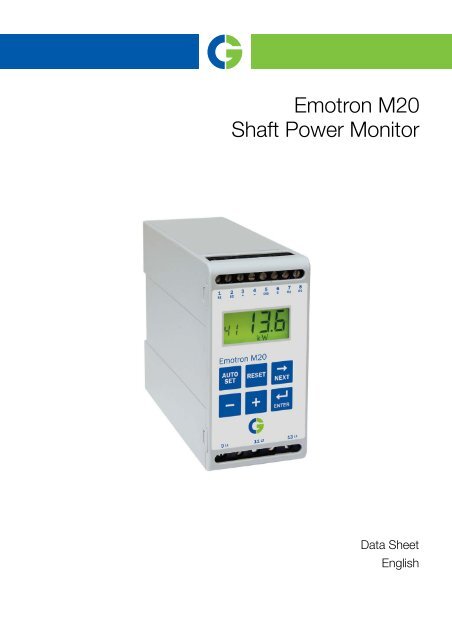
<strong>Emotron</strong> <strong>M20</strong><br />
<strong>Shaft</strong> <strong>Power</strong> <strong>Monitor</strong><br />
Data Sheet<br />
English
The <strong>M20</strong> provides complete flexibility in terms of the type<br />
of protection required for your application. You may select<br />
either overload and underload protection or simply overload<br />
with pre-alarm or underload with pre-alarm. Independent<br />
response delays are selectable for both overload and underload<br />
protection. Additional flexibility is provided in the<br />
form of programmable output relays, number of start<br />
attempts, number of reversing attempts etc.<br />
*)<br />
Fig. 1 <strong>Emotron</strong> <strong>M20</strong> and current transformer (CT), both for mounting on standard DIN rail 35mm.<br />
L1<br />
L2<br />
L3<br />
CTMxxx<br />
Fig. 2 Connection example<br />
K1<br />
U<br />
V<br />
W<br />
M<br />
9 L1<br />
11<br />
L2<br />
13<br />
L3<br />
3<br />
A+ A-<br />
<strong>M20</strong><br />
S1 S2<br />
1<br />
4<br />
2<br />
Please see<br />
CTM info<br />
NOTE: <strong>Monitor</strong><br />
voltage see<br />
Note below<br />
NOTE: Make sure that the monitor voltage range e.g.<br />
3x380-500 VAC matches the connected motor/line<br />
voltage, e.g. 3x 400 V.<br />
C<br />
R1<br />
R2<br />
<strong>Emotron</strong> <strong>M20</strong><br />
<strong>Shaft</strong> power monitor<br />
1 CG Drives & Automation 01-5959-01r0<br />
6<br />
7<br />
8<br />
DIG 5<br />
-Reset<br />
-Auto set<br />
- Block<br />
{<br />
Instruction manual<br />
English<br />
*)Terminal covers optional.<br />
NOTE: In power<br />
down, both relays<br />
are always N.O.<br />
K1<br />
PRE-<br />
ALARM<br />
Max. 240 VAC (alt. 0 VDC-)<br />
K1<br />
Stop<br />
Start<br />
N (alt. 48 VDC+)
Table 1 Motor and CT less than 100 A<br />
RATED MOTOR CURRENT [A]<br />
In order to ensure an accurate calibration of the <strong>M20</strong>, it is<br />
essential that you use the correct CTM and apply the exact<br />
number of windings in accordance with the tables.<br />
CURRENT TRANSFORMER TYPE and NUMBER OF WINDINGS<br />
CTM 010 CTM 025 CTM 050 CTM 100<br />
0.4 – 1.0 10<br />
1.01 – 2.0 5<br />
2.01 – 3.0 3<br />
3.1 – 5.0 2<br />
5.1 – 10.0 1<br />
10.1 – 12.5 2<br />
12.6 –25.0 1<br />
26.0 – 50.0 1<br />
51.0 – 100.0 1<br />
Table 2 CT greater than 100A<br />
RATED MOTOR CURRENT [A]<br />
101 – 150<br />
151 – 250<br />
251 – 500<br />
501 – 999<br />
NOTE: The current transformer (CTMxxx) must be placed in<br />
the same phase that is connected to terminal 9, phase L1,<br />
see Fig. 2.<br />
CURRENT TRANSFORMER TYPE and<br />
NUMBER OF PRIMARY WINDINGS<br />
150:5 + CTM 010<br />
1 + 2<br />
250:5 + CTM 010<br />
1 + 2<br />
500:5 + CTM 010<br />
1 + 2<br />
1000:5 + CTM 010<br />
1 + 2<br />
CG Drives & Automation 01-5959-01r0 2
Technical Data<br />
Dimensions (WxHxD)<br />
Article numbers<br />
45x90x115 mm (1.77" x 3.54" x 4.53")<br />
45mm (1.77’‘)<br />
115mm(4.53) ’‘<br />
Mounting 35 mm DIN rail 46277<br />
Weight 0.30 kg (10.5 oz)<br />
Supply voltage (±10%) 1x100-240 VAC, 3x100-240 VAC, 3x380-500 VAC 3x525-690 VAC<br />
Frequency 50 or 60 Hz<br />
Current input<br />
Current transformer; CTM 010, 025, 050 and 100. Input 0-55 mA. (>100 A extra transformer<br />
needed)<br />
<strong>Power</strong> consumption Max. 6 VA<br />
Start-up delay 1-999 s<br />
Hysteresis 0-50% of rated motor power<br />
Response delay max 0.1-500 s<br />
Response delay min 0.1-500 s<br />
Relay output 5 A/240 VAC Resistive, 1.5 A/240 VAC Pilot duty/AC12<br />
Analogue output Max. load 500 ohm<br />
Digital input<br />
Max. 240 VAC or 48 VDC. High: �24 VAC/DC,<br />
Low: 50 ms<br />
Fuse Max. 10 A<br />
Terminal wire size<br />
Use 75°C copper (CU) wire only. 0.2-4.0 mm 2 single core (AWG12). 0.2-2.5 mm 2 flexible core<br />
(AWG14), stripped length 8 mm (0.32")<br />
Terminal tightening torque 0.56-0.79 Nm (5-7 lb-in)<br />
Accuracy ±2%, ±1 unit cos phi>0.5; excl. current transformer; +20°C (+68°F)<br />
Repeatability ±1 unit 24h; +20°C (+68°F)<br />
Temperature tolerance Max. 0.1%/°C<br />
Operating temperature -20 to +50°C (-4°F to +122°F)<br />
Storage temperature -30 to +80°C (-22°F to +176°F)<br />
Protection class IP20<br />
RoHS directive 2002/95/EC<br />
Approved to CE (up to 690VAC), UL and cUL (up to 600 VAC)<br />
Article number Designation<br />
01-2520-20 <strong>Emotron</strong> <strong>M20</strong> 1x100-240/3x100-240 VAC<br />
01-2520-40 <strong>Emotron</strong> <strong>M20</strong> 3x380-500 VAC<br />
01-2520-50 <strong>Emotron</strong> <strong>M20</strong> 3x525-690 VAC<br />
35mm<br />
(1.38)’‘<br />
26mm<br />
(1.02)’‘<br />
3 CG Drives & Automation 01-5959-01r0<br />
90mm(3.54) ’‘
Technical Data for Current Transformer (CT)<br />
Type Dimension (WxQ) Weight* Mounting<br />
CTM 010 27 (35) xØ48mm 0.20 kg 35mm DIN rail 46277<br />
CTM 025 27 (35) xØ48mm 0.20 kg 35mm DIN rail 46277<br />
CTM 050 27 (35) xØ48mm 0.20 kg 35mm DIN rail 46277<br />
CTM 100 45 (58) xØ78mm 0.50 kg 35mm DIN rail 46277<br />
*)Weight including 1m (39 inch) cable. Please note that<br />
max. length of the CTM cable is 1 m and this cable cannot<br />
be extended.<br />
4.3<br />
35<br />
27<br />
Fig. 3 Current transformer, CTM xxx.<br />
Accessories and documentation<br />
EU (European Union) specifications<br />
EMC EN 50081-1, EN 50081-2,<br />
EN 50082-1, EN 61000-6-2<br />
Electrical safety IEC 947-5-1<br />
Rated insulated voltage 690 V<br />
Rated impulse<br />
withstand voltage 4000 V<br />
17<br />
48<br />
Article number Designation<br />
01-2471-10 Current Transformer (CT) CTM010, max. 10 A<br />
01-2471-20 Current Transformer (CT) CTM025, max. 25 A<br />
01-2471-30 Current Transformer (CT) CTM050, max. 50 A<br />
01-2471-40 Current Transformer (CT) CTM100, max. 100 A<br />
01-2368-00 Front Panel Kit 1 (2xterminal covers included)<br />
01-4136-01 2xTerminal covers<br />
01-5958-00 Instruction manual (Swedish)<br />
01-5958-01 Instruction manual (English)<br />
01-5958-02 Instruction manual (German)<br />
01-5958-03 Instruction manual (Dutch)<br />
01-5958-04 Instruction manual (Spanish)<br />
01-5958-08 Instruction manual (French)<br />
01-5958-09 Instruction manual (Russian)<br />
35<br />
45<br />
10.3<br />
Pollution degree 2<br />
Terminals 3, 4, 5, 6, 7 and 8 are basic insulated from the<br />
line.<br />
Terminals 3 and 4 are basic insulated from terminals 5, 6, 7<br />
and 8.<br />
CG Drives & Automation 01-5959-01r0 4<br />
42<br />
78
Parameter List<br />
Window Function Range Default Custom Symbol<br />
00 Alarm indication<br />
Measured shaft power in % of rated power 0-125 %<br />
01<br />
Measured shaft power in kW<br />
Measured shaft power in % of rated power<br />
0-745<br />
0-125<br />
kW<br />
%<br />
Measured shaft power in HP 0-999<br />
02 Measured line voltage 90-760 V V<br />
03 Measured current 0.00-999 A A<br />
04 Parameter lock 0-999<br />
�<br />
05 <strong>Monitor</strong> function<br />
OVER- and UNDERLOAD,<br />
OVERLOAD, UNDERLOAD<br />
OVERLOAD and<br />
UNDERLOAD<br />
11<br />
12<br />
13<br />
MAX Main Alarm<br />
(relay R1)<br />
MAX Pre-Alarm<br />
(relay R2)<br />
MIN Pre-Alarm<br />
(relay R2)<br />
0-125 100 %<br />
0-745 2.2 kW<br />
0-125 100 %<br />
0-999 3<br />
0-125 100 %<br />
0-745 2.2 kW<br />
0-125 100 %<br />
0-999 3<br />
0-125 0 %<br />
0-745 0 kW<br />
0-125 0 %<br />
0-999 0<br />
0-125 0 %<br />
14<br />
MIN Main Alarm<br />
(relay R1)<br />
0-745<br />
0-125<br />
0<br />
0<br />
kW<br />
%<br />
0-999 0<br />
21 MAX Main Alarm margin 0-100 16 %<br />
22 MAX Pre-Alarm margin 0-100 8 %<br />
23 MIN Pre-Alarm margin 0-100 8 %<br />
24 MIN Main Alarm margin 0-100 16 %<br />
31 Start delay 1-999 2 s<br />
32 Response delay, overload 0.1-500 s 0.5 s<br />
33 Hysteresis 0-50 0 %<br />
34 Response delay, underload 0.1-500s 0.5 s<br />
35* Pause/Reverse time 3-90 5 s<br />
36* Autoreset (start attempts) 0-5 0<br />
41 Rated motor power<br />
0.10-745 2.2 kW<br />
0.13-999 3<br />
42 Rated current 0.01-999 5.6 A<br />
43 Number of phases 1PH/3PH 3PH<br />
61 Main alarm latch on/OFF OFF<br />
62<br />
Alarm at no motor<br />
current<br />
on/OFF OFF<br />
5 CG Drives & Automation 01-5959-01r0
Window Function Range Default Custom Symbol<br />
63 Main Alarm relay R1 nc/no nc<br />
64 Pre-Alarm relay R2 nc/no no<br />
65* Relay function<br />
* See Special functions in chapter 9, <strong>Emotron</strong> <strong>M20</strong><br />
Instruction manual.<br />
** See Setting analogue output range in chapter 9,<br />
<strong>Emotron</strong> <strong>M20</strong> Instruction manual.<br />
0 = <strong>M20</strong><br />
1 = DLM<br />
2 = Reverse<br />
81 Digital input rES/AU/bLo rES<br />
82 Block timer 0.0-90 0.0 s<br />
91 Analogue output 0.20/4.20/20.0/20.4 0.20<br />
92** Analogue Out low value 0-100<br />
93** Analogue Out high value 0-125<br />
99 Factory defaults dEF/USr dEF<br />
CG Drives & Automation 01-5959-01r0 6<br />
0
CG Drives & Automation Sweden AB<br />
Mörsaregatan 12<br />
Box 222 25<br />
SE-250 24 Helsingborg<br />
Sweden<br />
T +46 42 16 99 00<br />
F +46 42 16 99 49<br />
www.emotron.com / www.cgglobal.com<br />
CG Drives & Automation, 01-5959-01r0 2012-04-02