
Create successful ePaper yourself
Turn your PDF publications into a flip-book with our unique Google optimized e-Paper software.
61200305L2-1B<br />
August 2004<br />
<strong>ATLAS</strong> <strong>550</strong><br />
<strong>System</strong> <strong>Manual</strong><br />
1200305L2 <strong>ATLAS</strong> <strong>550</strong> Chassis - AC Power (Domestic Version)<br />
1200306L2 <strong>ATLAS</strong> <strong>550</strong> Chassis - AC Power (International Version)<br />
1200<strong>550</strong>L2 <strong>ATLAS</strong> <strong>550</strong> Chassis - DC Power (Domestic Version)
Trademarks <strong>ATLAS</strong> <strong>550</strong> <strong>System</strong> <strong>Manual</strong><br />
Trademarks<br />
Any brand names and product names included in this manual are trademarks, registered trademarks, or<br />
trade names of their respective holders.<br />
To the Holder of the <strong>Manual</strong><br />
The contents of this manual are current as of the date of publication. ADTRAN reserves the right to change<br />
the contents without prior notice.<br />
In no event will ADTRAN be liable for any special, incidental, or consequential damages or for<br />
commercial losses even if ADTRAN has been advised thereof as a result of issue of this publication.<br />
About this <strong>Manual</strong><br />
This manual provides a complete description of the <strong>ATLAS</strong> <strong>550</strong> <strong>System</strong> and system software. The purpose<br />
of this manual is to provide the technician, system administrator, and manager with general and specific<br />
information related to the planning, installation, operation, and maintenance of the <strong>ATLAS</strong> <strong>550</strong>. This<br />
manual is arranged so that needed information can be quickly and easily found.<br />
901 Explorer Boulevard<br />
P.O. Box 140000<br />
Huntsville, AL 35814-4000<br />
Phone: (256) 963-8000<br />
© 2004 ADTRAN, Inc.<br />
All Rights Reserved.<br />
Printed in U.S.A.<br />
2 © 2004 ADTRAN, Inc. 61200305L2-1B
<strong>ATLAS</strong> <strong>550</strong> <strong>System</strong> <strong>Manual</strong> Revision History<br />
Revision History<br />
Document<br />
Revision<br />
Conventions<br />
Date Description of Changes<br />
A June 2003 Initial release of document. Previous version information found under<br />
document 61200305L1-1F. New version created to include updated<br />
form factor and hardware information.<br />
B August 2004 Revised to include more detailed mounting information and update<br />
compliance requirements.<br />
Notes provide additional useful information.<br />
Cautions signify information that could prevent service interruption.<br />
Warnings provide information that could prevent damage to the equipment or<br />
endangerment to human life.<br />
61200305L2-1B © 2004 ADTRAN, Inc. 3
Safety Instructions <strong>ATLAS</strong> <strong>550</strong> <strong>System</strong> <strong>Manual</strong><br />
Safety Instructions<br />
When using your telephone equipment, please follow these basic safety precautions to reduce the risk of<br />
fire, electrical shock, or personal injury:<br />
1. Do not use this product near water, such as a bathtub, wash bowl, kitchen sink, or laundry tub; in a<br />
wet basement; or near a swimming pool.<br />
2. Avoid using a telephone (other than a cordless-type) during an electrical storm. There is a remote<br />
risk of shock from lightning.<br />
3. Do not use the telephone to report a gas leak in the vicinity of the leak.<br />
4. Use only the power cord, power supply, and/or batteries indicated in the manual.<br />
5. Do not dispose of batteries in a fire. They may explode. Check with local codes for special<br />
disposal instructions.<br />
Save These Important Safety Instructions<br />
4 © 2004 ADTRAN, Inc. 61200305L2-1B
<strong>ATLAS</strong> <strong>550</strong> <strong>System</strong> <strong>Manual</strong> Compliance Information<br />
Compliance Information<br />
FCC regulations require that the following information be provided to the customer:<br />
1. This equipment complies with Part 68 of the FCC rules and requirements adopted by ACTA. On<br />
the equipment housing is a label showing the FCC registration number and ringer equivalence<br />
number (REN). If requested, provide this information to the telephone company.<br />
2. If this equipment causes harm to the telephone network, the telephone company may temporarily<br />
discontinue your service. If possible, advance notification is given; otherwise, notification is given<br />
as soon as possible. The telephone company will advise the customer of the right to file a<br />
complaint with the FCC.<br />
3. The telephone company may make changes in its facilities, equipment, operations, or procedures<br />
that could affect the proper operation of this equipment. Advance notification and the opportunity<br />
to maintain uninterrupted service are given.<br />
4. If experiencing trouble with this equipment, please contact ADTRAN for repair and warranty<br />
information. The telephone company may require this equipment to be disconnected from the<br />
network until the problem is been corrected or it is certain the equipment is not malfunctioning.<br />
5. This unit contains no user-serviceable parts.<br />
6. An FCC compliant telephone cord with a modular plug is provided with this equipment. This<br />
equipment is designed to be connected to the telephone network or premises wiring using an FCC<br />
compatible modular jack, which is complaint with Part 68 and requirements adopted by ACTA.<br />
7. The following information may be required when applying to your local telephone company for<br />
leased line facilities.<br />
Part # FCC Reg. Number Service Type REN/SOC FIC USOC<br />
1200307L1 HDCUSA-34602-DE-N<br />
04DU9-BN<br />
1200307L2 US:HDCDENAN1200307L2 04DU9-BN<br />
1200314L1 HDCUSA-34601-DE-N 04DU9-BN<br />
1.544 Mbps - SF<br />
1200314L2<br />
1200346L1<br />
US:HDCDENAN1200314L2<br />
US:HDCDENAN1200346L1<br />
1.544 Mbps - SF and B8ZS<br />
1.544 Mbps - ESF<br />
6.0 N<br />
04DU9-DN<br />
04DU9-1KN<br />
1200346L2 US:HDCDENAN1200346L2<br />
1.544 Mbps - ESF and B8ZS<br />
04DU9-1KN<br />
1200755L1 HDCUSA-34601-DE-N 04DU9-1SN<br />
RJ-48C<br />
1200755L2 US:HDCDENAN1200755L2 04DU9-1SN<br />
1200310L1 HDCUSA-34761-KX-N Analog Loop Start 0.1B/9.0F 02LS2 RJ-11C<br />
1200329L1 HDCUSA-34761-KX-N Analog Loop Start 0.1B/9.0F 02LS2 RJ-11C<br />
1200341L1 HDCUSA-44569-MD-E Analog Loop Start 0.8 B N/A RJ-11C<br />
1200315L1 HDCUSA-34956-DE-N Basic Rate ISDN 6.0 N 02IS5 RJ-49C<br />
1200327L1 US:HDCDENAN1200327L1 Basic Rate ISDN 6.0 N 02IS5 RJ-49C<br />
1200764L1 US:HDCXDNAN1200764L1 Basic Rate ISDN 6.0 N 02IS5 RJ-49C<br />
8. The REN is used to determine the quantity of devices which may be connected to the telephone<br />
line and still have all of those devices ring when the number is called. Excessive RENs on the<br />
telephone line may result in the devices not ringing in response to an incoming call. In most, but<br />
not all areas, the sum of RENs should not exceed five (5.0). To be certain of the number of devices<br />
that may be connected to a line, as determined by the total RENs, contact the local telephone<br />
company.<br />
9. This equipment may not be used on coin service provided by the telephone company. Connection<br />
to party lines is subject to state tariffs. Contact your state public utility commission or corporation<br />
commission for information.<br />
61200305L2-1B © 2004 ADTRAN, Inc. 5
FCC Radio Frequency Interference Statement <strong>ATLAS</strong> <strong>550</strong> <strong>System</strong> <strong>Manual</strong><br />
FCC Radio Frequency Interference Statement<br />
This equipment has been tested and found to comply with the limits for a Class A digital device, pursuant<br />
to Part 15 of the FCC Rules. These limits are designed to provide reasonable protection against harmful<br />
interference when the equipment is operated in a commercial environment. This equipment generates,<br />
uses, and can radiate radio frequency energy and, if not installed and used in accordance with the<br />
instruction manual, may cause harmful interference to radio frequencies. Operation of this equipment in a<br />
residential area is likely to cause harmful interference in which case the user will be required to correct the<br />
interference at his own expense.<br />
Shielded cables must be used with this unit to ensure compliance with Class A FCC limits.<br />
Changes or modifications to this unit not expressly approved by the party responsible<br />
for compliance could void the user’s authority to operate the equipment.<br />
6 © 2004 ADTRAN, Inc. 61200305L2-1B
<strong>ATLAS</strong> <strong>550</strong> <strong>System</strong> <strong>Manual</strong> Industry Canada Compliance Information<br />
Industry Canada Compliance Information<br />
Notice: The Industry Canada label applied to the product (identified by the Industry Canada logo or the<br />
“IC:” in front of the certification/registration number) signifies that the Industry Canada technical<br />
specifications were met.<br />
Notice: The Ringer Equivalence Number (REN) for this terminal equipment is supplied in the<br />
documentation or on the product labeling/markings. The REN assigned to each terminal device indicates<br />
the maximum number of terminals that can be connected to a telephone interface. The termination on an<br />
interface may consist of any combination of devices subject only to the requirement that the sum of the<br />
RENs of all the devices should not exceed five (5).<br />
Canadian Emissions Requirements<br />
This digital apparatus does not exceed the Class A limits for radio noise emissions from digital apparatus<br />
as set out in the interference-causing equipment standard entitled “Digital Apparatus,” ICES-003 of the<br />
Department of Communications.<br />
Cet appareil numérique respecte les limites de bruits radioelectriques applicables aux appareils numériques<br />
de Class A prescrites dans la norme sur le materiel brouilleur: “Appareils Numériques,” NMB-003 edictee<br />
par le ministre des Communications.<br />
61200305L2-1B © 2004 ADTRAN, Inc. 7
Affidavit Requirements for Connection to Digital Services <strong>ATLAS</strong> <strong>550</strong> <strong>System</strong> <strong>Manual</strong><br />
Affidavit Requirements for Connection to Digital Services<br />
• An affidavit is required to be given to the telephone company whenever digital terminal equipment<br />
without encoded analog content and billing protection is used to transmit digital signals containing<br />
encoded analog content which are intended for eventual conversion into voiceband analog signal and<br />
transmitted on the network.<br />
• The affidavit shall affirm that either no encoded analog content or billing information is being<br />
transmitted or that the output of the device meets Part 68 encoded analog content or billing protection<br />
specifications.<br />
• End user/customer will be responsible to file an affidavit with the local exchange carrier when<br />
connecting unprotected CPE to a 1.544 Mbps or subrate digital service.<br />
• Until such time as subrate digital terminal equipment is registered for voice applications, the affidavit<br />
requirements for subrate services are waived.<br />
8 © 2004 ADTRAN, Inc. 61200305L2-1B
<strong>ATLAS</strong> <strong>550</strong> <strong>System</strong> <strong>Manual</strong> Affidavit for Connection Of Customer Premises Equipment<br />
Affidavit for Connection Of Customer Premises Equipment<br />
to 1.544 Mbps And/or Subrate Digital Services<br />
For the work to be performed in the certified territory of ___________________(telco name)<br />
State of ________________<br />
County of ________________<br />
I, _______________________ (name), _____________________________(business address),<br />
____________________ (telephone number) being duly sworn, state:<br />
I have responsibility for the operation and maintenance of the terminal equipment to be connected<br />
to 1.544 Mbps and/or ________ subrate digital services. The terminal equipment to be connected<br />
complies with Part 68 of the FCC rules except for the encoded analog content and billing protection<br />
specifications. With respect to encoded analog content and billing protection:<br />
( ) I attest that all operations associated with the establishment, maintenance, and adjustment of the<br />
digital CPE with respect to analog content and encoded billing protection information continuously<br />
complies with Part 68 of the FCC Rules and Regulations.<br />
( ) The digital CPE does not transmit digital signals containing encoded analog content or billing<br />
information which is intended to be decoded within the telecommunications network.<br />
( ) The encoded analog content and billing protection is factory set and is not under the control of the<br />
customer.<br />
I attest that the operator(s)/maintainer(s) of the digital CPE responsible for the establishment,<br />
maintenance, and adjustment of the encoded analog content and billing information has (have) been<br />
trained to perform these functions by successfully having completed one of the following (check<br />
appropriate blocks):<br />
( ) A. A training course provided by the manufacturer/grantee of the equipment used to encode analog<br />
signals; or<br />
( ) B. A training course provided by the customer or authorized representative, using training materials<br />
and instructions provided by the manufacturer/grantee of the equipment used to encode analog<br />
signals; or<br />
( ) C. An independent training course (e.g., trade school or technical institution) recognized by the<br />
manufacturer/grantee of the equipment used to encode analog signals; or<br />
( ) D. In lieu of the preceding training requirements, the operator(s)/maintainer(s) is (are) under the<br />
control of a supervisor trained in accordance with _________ (circle one) above.<br />
61200305L2-1B © 2004 ADTRAN, Inc. 9
Affidavit for Connection Of Customer Premises Equipment <strong>ATLAS</strong> <strong>550</strong> <strong>System</strong> <strong>Manual</strong><br />
I agree to provide ______________________ (telco’s name) with proper documentation to<br />
demonstrate compliance with the information as provided in the preceding paragraph, if so<br />
requested.<br />
_________________________________Signature<br />
_________________________________Title<br />
_________________________________ Date<br />
Transcribed and sworn to before me<br />
This ________ day of _______________, _______<br />
_________________________________<br />
Notary Public<br />
My commission expires:<br />
_________________________________<br />
10 © 2004 ADTRAN, Inc. 61200305L2-1B
<strong>ATLAS</strong> <strong>550</strong> <strong>System</strong> <strong>Manual</strong> Warranty and Customer Service<br />
Warranty and Customer Service<br />
ADTRAN will replace or repair this product within the warranty period if it does not meet its published<br />
specifications or fails while in service. Warranty information can be found at: http://support.adtran.com<br />
(Click on Warranty and Repair Information, under Support.)<br />
Product Registration<br />
Registering your product helps ensure complete customer satisfaction. Please take time to register your<br />
products on line at http://support.adtran.com. Click on Product Registration under Support.<br />
Customer Service, Product Support Information, and Training<br />
A return material authorization (RMA) is required prior to returning equipment to ADTRAN. For service,<br />
RMA requests, training, or more information, use the following contact information:.<br />
Repair and Return<br />
If you determine that a repair is needed, please contact our Customer and Product Service (CaPS)<br />
department to have an RMA number issued. CaPS should also be contacted to obtain information<br />
regarding equipment currently in house or possible fees associated with repair.<br />
CaPS Department (256) 963-8722<br />
Identify the RMA number clearly on the package (below address), and return to the following address:<br />
ADTRAN Customer and Product Service<br />
901 Explorer Blvd. (East Tower)<br />
Huntsville, Alabama 35806<br />
RMA # _____________<br />
61200305L2-1B © 2004 ADTRAN, Inc. 11
Customer Service, Product Support Information, and Training <strong>ATLAS</strong> <strong>550</strong> <strong>System</strong> <strong>Manual</strong><br />
Pre-Sales Inquiries and Applications Support<br />
Your reseller should serve as the first point of contact for support. If additional pre-sales support is needed,<br />
the ADTRAN Support web site provides a variety of support services such as a searchable knowledge<br />
base, latest product documentation, application briefs, case studies, and a link to submit a question to an<br />
Applications Engineer. All of this, and more, is available at:<br />
http://support.adtran.com<br />
When needed, further pre-sales assistance is available by calling our Applications Engineering<br />
Department.<br />
Post-Sale Support<br />
Your reseller should serve as the first point of contact for support. If additional support is needed, the<br />
ADTRAN Support web site provides a variety of support services such as a searchable knowledge base,<br />
updated firmware releases, latest product documentation, service request ticket generation and<br />
trouble-shooting tools. All of this, and more, is available at:<br />
When needed, further post-sales assistance is available by calling our Technical Support Center. Please<br />
have your unit serial number available when you call.<br />
Installation and Maintenance Support<br />
The ADTRAN Custom Extended Services (ACES) program offers multiple types and levels of installation<br />
and maintenance services which allow you to choose the kind of assistance you need. This support is<br />
available at:<br />
For questions, call the ACES Help Desk.<br />
Applications Engineering (800) 615-1176<br />
http://support.adtran.com<br />
Technical Support (888) 4ADTRAN<br />
http://www.adtran.com/aces<br />
ACES Help Desk (888) 874-ACES (2237)<br />
12 © 2004 ADTRAN, Inc. 61200305L2-1B
<strong>ATLAS</strong> <strong>550</strong> <strong>System</strong> <strong>Manual</strong> Customer Service, Product Support Information, and Training<br />
Training<br />
The Enterprise Network (EN) Technical Training Department offers training on our most popular products.<br />
These courses include overviews on product features and functions while covering applications of<br />
ADTRAN's product lines. ADTRAN provides a variety of training options, including customized training<br />
and courses taught at our facilities or at your site. For more information about training, please contact your<br />
Territory Manager or the Enterprise Training Coordinator.<br />
Training Phone (800) 615-1176, ext. 7500<br />
Training Fax (256) 963-6700<br />
Training Email training@adtran.com<br />
61200305L2-1B © 2004 ADTRAN, Inc. 13
Customer Service, Product Support Information, and Training <strong>ATLAS</strong> <strong>550</strong> <strong>System</strong> <strong>Manual</strong><br />
14 © 2004 ADTRAN, Inc. 61200305L2-1B
Table of Contents<br />
Section 1 <strong>System</strong> Description . . . . . . . . . . . . . . . . . . . . . . . . . . . . . . . . . . . . . . . . 17<br />
Provides an overview of the <strong>ATLAS</strong> <strong>550</strong> <strong>System</strong>.<br />
Section 2 Engineering Guidelines . . . . . . . . . . . . . . . . . . . . . . . . . . . . . . . . . . . . . 25<br />
Provides equipment dimensions, power requirements, front panel design, back panel design,<br />
LEDs, and at-a-glance specifications.<br />
Section 3 Network Turnup Procedure. . . . . . . . . . . . . . . . . . . . . . . . . . . . . . . . . . 51<br />
Provides shipment contents list, grounding instructions, mounting options, and specifics of supplying<br />
power to the unit.<br />
Section 4 User Interface Guide . . . . . . . . . . . . . . . . . . . . . . . . . . . . . . . . . . . . . . . 63<br />
Provides detailed descriptions of all menu options and configuration parameters available for<br />
the <strong>ATLAS</strong> <strong>550</strong>.<br />
Section 5 Detail Level Procedures. . . . . . . . . . . . . . . . . . . . . . . . . . . . . . . . . . . . 309<br />
DLP-1 Connecting a VT100 Terminal or PC to the ADMIN or CRAFT Port. . . . . . . . . . . . . . 311<br />
DLP-2 Logging in to the <strong>ATLAS</strong> <strong>550</strong> . . . . . . . . . . . . . . . . . . . . . . . . . . . . . . . . . . . . . . . . . . . . 313<br />
DLP-3 Setting IP Parameters for the <strong>ATLAS</strong> <strong>550</strong> . . . . . . . . . . . . . . . . . . . . . . . . . . . . . . . . . . . 315<br />
DLP-4 Verifying Communications Over an IP LAN . . . . . . . . . . . . . . . . . . . . . . . . . . . . . . . . . 317<br />
DLP-5 Adding and Removing Users and Changing Password Security Levels . . . . . . . . . . . . 321<br />
DLP-6 Updating the Firmware Using TFTP . . . . . . . . . . . . . . . . . . . . . . . . . . . . . . . . . . . . . . . 323<br />
DLP-7 Updating the Firmware Using XMODEM . . . . . . . . . . . . . . . . . . . . . . . . . . . . . . . . . . . 327<br />
DLP-8 Saving the Current Configuration Using TFTP . . . . . . . . . . . . . . . . . . . . . . . . . . . . . . . 331<br />
DLP-9 Loading a Configuration Using TFTP . . . . . . . . . . . . . . . . . . . . . . . . . . . . . . . . . . . . . . 333<br />
DLP-10 Saving and Transferring a Current Configuration Using XMODEM . . . . . . . . . . . . . . 335<br />
DLP-11 Loading a Configuration Using XMODEM . . . . . . . . . . . . . . . . . . . . . . . . . . . . . . . . . . 337<br />
DLP-12 Connecting the <strong>ATLAS</strong> <strong>550</strong> to an External Modem . . . . . . . . . . . . . . . . . . . . . . . . . . . 339<br />
DLP-13 Using the ADTRAN Utility Syslog (Event Log) . . . . . . . . . . . . . . . . . . . . . . . . . . . . . . 341<br />
DLP-14 Connecting the Alarm Contacts . . . . . . . . . . . . . . . . . . . . . . . . . . . . . . . . . . . . . . . . . . . 345<br />
DLP-15 Using the Alarm Connections and the ACO Button. . . . . . . . . . . . . . . . . . . . . . . . . . . . 349<br />
Section 6 Configuration Guides. . . . . . . . . . . . . . . . . . . . . . . . . . . . . . . . . . . . . . 351<br />
CFG-1 Dial Backup for Dedicated T1 Circuits . . . . . . . . . . . . . . . . . . . . . . . . . . . . . . . . . . . . . 353<br />
Section 7 <strong>System</strong> Event Logging. . . . . . . . . . . . . . . . . . . . . . . . . . . . . . . . . . . . . 365<br />
Explains the <strong>System</strong> Event Logging messages for the <strong>ATLAS</strong> <strong>550</strong> and provides instructions for<br />
configuring the Event Log.<br />
Section 8 ADTRAN Utilities . . . . . . . . . . . . . . . . . . . . . . . . . . . . . . . . . . . . . . . . . 379<br />
Provides instructions for configuring and using the ADTRAN Utilities software programs including<br />
Telnet, VT100, Syslog, and TFTP.<br />
Section 9 MIBs. . . . . . . . . . . . . . . . . . . . . . . . . . . . . . . . . . . . . . . . . . . . . . . . . . . . 389<br />
Provides a listing of SNMP Management Information Bases (MIBs) supported by the<br />
<strong>ATLAS</strong> <strong>550</strong>. Traps supported for each MIB are also listed.<br />
61200305L2-1B © 2004 ADTRAN, Inc. 15
Table of Contents <strong>ATLAS</strong> <strong>550</strong> <strong>System</strong> <strong>Manual</strong><br />
16 © 2004 ADTRAN, Inc. 61200305L2-1B
SYSTEM DESCRIPTION<br />
Provides an overview of the <strong>ATLAS</strong> <strong>550</strong> <strong>System</strong>.<br />
CONTENTS<br />
<strong>System</strong> Overview. . . . . . . . . . . . . . . . . . . . . . . . . . . . . . . . . . . . . . . . . . . . . . . . . . . . . . . . . . . . . . . . 16<br />
Features and Benefits . . . . . . . . . . . . . . . . . . . . . . . . . . . . . . . . . . . . . . . . . . . . . . . . . . . . . . . . . . . 16<br />
Configuration and Management . . . . . . . . . . . . . . . . . . . . . . . . . . . . . . . . . . . . . . . . . . . . . . . . . 16<br />
Software Upgradeable . . . . . . . . . . . . . . . . . . . . . . . . . . . . . . . . . . . . . . . . . . . . . . . . . . . . . . . . 16<br />
Signaling Support . . . . . . . . . . . . . . . . . . . . . . . . . . . . . . . . . . . . . . . . . . . . . . . . . . . . . . . . . . . . 16<br />
ISDN Switch Types . . . . . . . . . . . . . . . . . . . . . . . . . . . . . . . . . . . . . . . . . . . . . . . . . . . . . . . . . . . 16<br />
Dedicated Connection Maps. . . . . . . . . . . . . . . . . . . . . . . . . . . . . . . . . . . . . . . . . . . . . . . . . . . . 17<br />
Switched Connection Maps. . . . . . . . . . . . . . . . . . . . . . . . . . . . . . . . . . . . . . . . . . . . . . . . . . . . . 17<br />
Testing . . . . . . . . . . . . . . . . . . . . . . . . . . . . . . . . . . . . . . . . . . . . . . . . . . . . . . . . . . . . . . . . . . . . 17<br />
Performance Monitoring . . . . . . . . . . . . . . . . . . . . . . . . . . . . . . . . . . . . . . . . . . . . . . . . . . . . . . . 17<br />
Frame Relay . . . . . . . . . . . . . . . . . . . . . . . . . . . . . . . . . . . . . . . . . . . . . . . . . . . . . . . . . . . . . . . . 17<br />
PPP Switching. . . . . . . . . . . . . . . . . . . . . . . . . . . . . . . . . . . . . . . . . . . . . . . . . . . . . . . . . . . . . . . 17<br />
Option Modules . . . . . . . . . . . . . . . . . . . . . . . . . . . . . . . . . . . . . . . . . . . . . . . . . . . . . . . . . . . . . . . . 18<br />
T1/PRI Network Interface Module (P/N 1200307L1/L2) . . . . . . . . . . . . . . . . . . . . . . . . . . . . . . . 18<br />
E1/PRA Network Interface Module (P/N 1200308L1). . . . . . . . . . . . . . . . . . . . . . . . . . . . . . . . . 18<br />
Modem Management Network Module (P/N 1200341L1). . . . . . . . . . . . . . . . . . . . . . . . . . . . . . 19<br />
BRI DBU Network Interface Module (P/N 1200327L1) . . . . . . . . . . . . . . . . . . . . . . . . . . . . . . . . 19<br />
Dual Nx 56/64 Option Module (P/N 1200311L1). . . . . . . . . . . . . . . . . . . . . . . . . . . . . . . . . . . . . 19<br />
Dual USSI Option Module (P/N 1200754L1). . . . . . . . . . . . . . . . . . . . . . . . . . . . . . . . . . . . . . . . 19<br />
Dual/Quad T1/PRI Option Module (P/N 1200314L1/L2 and 1200755L1/L2) . . . . . . . . . . . . . . . 19<br />
Quad Basic Rate ISDN (U-Interface) Option Module (P/N1200315L1) . . . . . . . . . . . . . . . . . . . 19<br />
Quad Basic Rate ISDN (S/T-Interface) Option Module (P/N 1200764L1) . . . . . . . . . . . . . . . . . 19<br />
Octal/Quad FXS Option Module (P/N 1200309L1/1200328L1) . . . . . . . . . . . . . . . . . . . . . . . . . 19<br />
Octal/Quad FXO Option Module (P/N 1200310L1/1200329L1) . . . . . . . . . . . . . . . . . . . . . . . . . 20<br />
Octal E&M Option Module (P/N 1200313L1) . . . . . . . . . . . . . . . . . . . . . . . . . . . . . . . . . . . . . . . 20<br />
Legacy Data Option Module (P/N 1200342L1) . . . . . . . . . . . . . . . . . . . . . . . . . . . . . . . . . . . . . . 20<br />
NxT1 HSSI/V.35 Option Module (P/N 1200346L2). . . . . . . . . . . . . . . . . . . . . . . . . . . . . . . . . . . 20<br />
Octal Ethernet Switch Option Module (P/N 1200766L1). . . . . . . . . . . . . . . . . . . . . . . . . . . . . . . 20<br />
Resource Host Module (P/N 1200324L1) . . . . . . . . . . . . . . . . . . . . . . . . . . . . . . . . . . . . . . . . . . 20<br />
4, 8, 16, 24 Channel Voice Compression Resource Modules (P/N 1200312Lx) . . . . . . . . . . . . 20<br />
32 Channel ADPCM Resource Module (P/N 1200752L1) . . . . . . . . . . . . . . . . . . . . . . . . . . . . . 20<br />
Nx 56/64 BONDing Resource Module (P/N 1200326L1) . . . . . . . . . . . . . . . . . . . . . . . . . . . . . . 21<br />
61200305L2-1B © 2004 ADTRAN, Inc. 17
Section 1 <strong>System</strong> Description <strong>ATLAS</strong> <strong>550</strong> <strong>System</strong> <strong>Manual</strong><br />
1. SYSTEM OVERVIEW<br />
The <strong>ATLAS</strong> <strong>550</strong> is a modular, highly scalable platform that provides robust solutions for the wide-area<br />
communication needs of small-to-medium corporations and network access providers. The <strong>ATLAS</strong> <strong>550</strong> is<br />
an Integrated Access <strong>System</strong> with extensive support of dedicated bandwidth management and access<br />
switching. It contains a high-performance CPU and powerful communications drivers which support<br />
applications such as frame relay, dial-backup, and PPP (point-to-point protocol).<br />
The <strong>ATLAS</strong> <strong>550</strong> architecture also includes a packet and circuit switching bussing scheme. The result is a<br />
system capable of supporting bandwidth requirements of up to nine T1 circuits or five Primary Rate ISDN<br />
(PRI) circuits. Designed for standalone, rackmount, or wallmount installations, the <strong>ATLAS</strong> <strong>550</strong> base unit<br />
provides two hot-swappable network interfaces and four expansion slots that accommodate hot-swappable<br />
option modules for a variety of applications. A 10/100BaseT Ethernet connection for IP routing and<br />
network management is standard with the <strong>ATLAS</strong> <strong>550</strong> base unit.<br />
With the <strong>ATLAS</strong> <strong>550</strong>, you can consolidate voice, data, and video applications into a single platform while<br />
optimizing wide area bandwidth and reducing equipment costs. The <strong>ATLAS</strong> <strong>550</strong> architecture and the four<br />
expansion slots accept a variety of modules, making it one of the most versatile access systems on the<br />
market.<br />
2. FEATURES AND BENEFITS<br />
The following is a brief list of <strong>ATLAS</strong> <strong>550</strong> features and benefits:<br />
Configuration and Management<br />
• VT100 emulation<br />
• SNMP, per MIB II (RFC1213), DS1/E1 MIB (RFC1406), Frame Relay MIB (RFC1315), and<br />
ADTRAN private MIBs<br />
• Telnet<br />
• Dial-up remote management via optional Modem Management Network Module (P/N 1200341L1)<br />
• Six levels of password protection and privileges<br />
Software Upgradeable<br />
• Flash memory<br />
• TFTP download<br />
• XMODEM via CRAFT or ADMIN ports<br />
Signaling Support<br />
• ISDN D Channel<br />
• Robbed bit, E&M, Ground Start, Loop Start<br />
• Convert between Robbed Bit Signaling and ISDN D Channel<br />
• Direct Inward Dialing<br />
ISDN Switch Types<br />
• 5ESS, DMS-100, National ISDN, 4ESS, EuroISDN<br />
18 © 2004 ADTRAN, Inc. 61200305L2-1B
<strong>ATLAS</strong> <strong>550</strong> <strong>System</strong> <strong>Manual</strong> Section 1 <strong>System</strong> Description<br />
Dedicated Connection Maps<br />
• Up to five connection maps<br />
• Time of day and day of week configurable<br />
• Preserves signaling through cross-connect<br />
• No effect on nonconfigured channels<br />
Switched Connection Maps<br />
• Inbound and outbound call filtering and blocking<br />
Testing<br />
• Local and remote: payload/line, V.54 (depending on installed modules)<br />
• Patterns: 511, QRSS, all ones, all zeros (depending on installed modules)<br />
Performance Monitoring<br />
• Reports: Information stored for last 24 hours in 15-minute increments<br />
• Performance statistics per TR54016, T1.403, RFC1406<br />
• Alarm reporting per TR54016, T1.403<br />
Frame Relay<br />
• Routes Internet Protocol (IP) traffic between the Ethernet port and a public frame relay network, a<br />
private frame relay network, or a point-to-point network<br />
• Concentrates IP traffic from a public or private frame relay network and passes frame relay data with<br />
RFC 1490 encapsulation to one or more serial ports (V.35)<br />
• Passes <strong>System</strong>s Network Architecture (SNA), Bisync, and other legacy protocols between a public or<br />
private frame relay network and an external DTE running Frame Relay to the <strong>ATLAS</strong> <strong>550</strong><br />
• Performs voice compression/decompression (G.723.1) and interfaces to either a Private Branch<br />
Exchange (PBX) or the Public Switched Telephone Network (PSTN) (requires an additional option<br />
module, the VCOM Module—P/N 1200312Lx)<br />
• Performs voice packetization (G.711 or Transparent) or voice compression/decompression (G.726) and<br />
interfaces to either a PBX or the PSTN (requires an additional option module, the 32-Channel ADPCM<br />
Resource Module—P/N 1200752L1)<br />
• Supports LMI, Annex D, or Annex A signaling on frame relay connections<br />
PPP Switching<br />
• Supports up to 100 simultaneous PPP connections<br />
• Performs PAP, CHAP, or EAP authentication methods on a per-connection basis<br />
• Includes keepalive functionality for PPP connections<br />
• Provides capability for numbered or unnumbered PPP interfaces<br />
61200305L2-1B © 2004 ADTRAN, Inc. 19
Section 1 <strong>System</strong> Description <strong>ATLAS</strong> <strong>550</strong> <strong>System</strong> <strong>Manual</strong><br />
3. OPTION MODULES<br />
Each of the following <strong>ATLAS</strong> <strong>550</strong> option modules is hot-swappable:<br />
• T1/PRI Network Interface Module (P/N 1200307L1/L2)<br />
• E1/PRA Network Interface Module (P/N 1200308L1)<br />
• Modem Management Network Module (P/N 1200341L1)<br />
• BRI DBU Network Interface Module (P/N 1200327L1)<br />
• Dual Nx 56/64 Option Module (P/N 1200311L1)<br />
• Dual USSI Option Module (P/N 1200754L1)<br />
• Dual/Quad T1/PRI Option Module (P/N 1200314L1/L2 and 1200755L1/L2)<br />
• Quad Basic Rate ISDN (U-Interface) Option Module (P/N1200315L1)<br />
• Quad Basic Rate ISDN (S/T-Interface) Option Module (P/N1200764L1)<br />
• Octal/Quad FXS Option Module (P/N 1200309L1/1200328L1)<br />
• Octal/Quad FXO Option Module (P/N 1200310L1/1200329L1)<br />
• Octal E&M Option Module (P/N 1200313L1)<br />
• Octal Ethernet Switch Option Module (P/N 1200766L1)<br />
• Resource Host Module (P/N 1200324L1)<br />
• 4, 8, 16, 24 Channel Voice Compression Resource Modules (P/N 1200312Lx)<br />
• 32 Channel ADPCM Resource Module (P/N 1200752L1)<br />
• Nx 56/64 BONDing Resource Module (P/N 1200326L1)<br />
• Legacy Data Option Module (P/N 1200342L1)<br />
• NxT1 HSSI/V.35 Option Module (P/N 1200346L2)<br />
Replacing an option module with a different module type will result in configuration loss.<br />
Each option module contains a variety of performance and alarm status information. Although default<br />
values reflect the most common configurations, several features of each module are user-configurable. All<br />
option modules contain an extensive self-test as well as tests designed for the technology they incorporate.<br />
T1/PRI Network Interface Module (P/N 1200307L1/L2)<br />
The T1/PRI Network Interface Module provides one channelized T1 or PRI interface. This interface<br />
operates in DS-1 or DSX-1 mode and can deliver timing for the system. The <strong>ATLAS</strong> <strong>550</strong> domestic system<br />
(P/N 1200305L2) ships with one installed T1/PRI Network Interface Module.<br />
E1/PRA Network Interface Module (P/N 1200308L1)<br />
The E1/PRA Network Interface Module provides one channelized E1 or PRA interface using either a<br />
standard DB-15 or BNC connector. This interface operates in CCS or CAS signaling mode and can deliver<br />
timing for the system. The <strong>ATLAS</strong> <strong>550</strong> international system (P/N 1200306L2) ships with one installed<br />
E1/PRA Network Interface Module.<br />
20 © 2004 ADTRAN, Inc. 61200305L2-1B
<strong>ATLAS</strong> <strong>550</strong> <strong>System</strong> <strong>Manual</strong> Section 1 <strong>System</strong> Description<br />
Modem Management Network Module (P/N 1200341L1)<br />
The Modem Management Network Module provides a single analog interface (RJ-11) for dial-up remote<br />
management of the <strong>ATLAS</strong> <strong>550</strong> <strong>System</strong>. The internal modem supports connection rates from 2400 bps to<br />
33.6 kbps and performs standard data modulation, error correction, and data compression.<br />
BRI DBU Network Interface Module (P/N 1200327L1)<br />
The BRI DBU Network Interface Module provides a single Basic Rate ISDN (BRI) U interface capable of<br />
operating in either NT or LT mode and delivering timing for the system. The BRI DBU Network Interface<br />
Module supports two independent calls or one BONDed call. All BONDing functionality is provided on<br />
the module, so the BONDing resource module (1200326L1) is not required.<br />
Dual Nx 56/64 Option Module (P/N 1200311L1)<br />
The Dual Nx 56/64 Module provides two synchronous V.35 DTE ports that can operate from 56 kbps to<br />
2.048 Mbps in steps of 56 or 64 kbps. Either port can deliver timing for the system.<br />
Dual USSI Option Module (P/N 1200754L1)<br />
The Dual USSI Option Module provides two synchronous DTE ports that can operate from 56 kbps to<br />
2.048 Mbps in steps of 56 or 64 kbps. Either port can deliver timing for the system. Using the appropriate<br />
adapter cables, the Dual USSI Option Module can provide the following interface types: EIA-530,<br />
EIA-530A, RS-449, RS-232, and CCITT X.21.<br />
Dual/Quad T1/PRI Option Module (P/N 1200314L1/L2 and 1200755L1/L2)<br />
The Dual/Quad T1/PRI Module provides two or four channelized T1 or PRI interfaces. Each interface can<br />
operate independently in DS-1 or DSX-1 mode, and any port can deliver timing for the system.<br />
Quad Basic Rate ISDN (U-Interface) Option Module (P/N1200315L1)<br />
The Quad Basic Rate ISDN (U) Module provides four BRI U interfaces, each capable of operating in<br />
either NT or LT mode. When operating in NT mode, any port can deliver timing for the system.<br />
Quad Basic Rate ISDN (S/T-Interface) Option Module (P/N 1200764L1)<br />
The Quad Basic Rate ISDN (S/T) Module provides four BRI S/T interfaces, each capable of operating in<br />
LT mode.<br />
Octal/Quad FXS Option Module (P/N 1200309L1/1200328L1)<br />
The Octal/Quad FXS Option Modules provide eight or four analog voice-grade interfaces. Each interface<br />
provides talk battery, off-hook supervision, E&M signaling conversion, and ringing in loop-start or<br />
ground-start operation. Call progress tones, where necessary, are provided to the modules by the<br />
<strong>ATLAS</strong> <strong>550</strong> base unit.<br />
61200305L2-1B © 2004 ADTRAN, Inc. 21
Section 1 <strong>System</strong> Description <strong>ATLAS</strong> <strong>550</strong> <strong>System</strong> <strong>Manual</strong><br />
Octal/Quad FXO Option Module (P/N 1200310L1/1200329L1)<br />
The Octal/Quad FXO Option Modules provide eight or four analog voice-grade interfaces. Each interface<br />
supports loop-start and ground-start operation. Applications include termination of analog PSTN trunks<br />
and connections to PBX station-side interfaces (Off Premise Extension – OPX).<br />
Octal E&M Option Module (P/N 1200313L1)<br />
The Octal E&M Option Module provides eight analog voice-grade interfaces (2-wire or 4-wire) for use as<br />
tie-trunks (using E&M signaling) or dedicated transmission only (TO) interfaces (for additional data<br />
services). The module supports E&M signaling types 1-5.<br />
Legacy Data Option Module (P/N 1200342L1)<br />
The Legacy Data Option Module provides four EIA-232 or V.35 interfaces (or any combination up to four)<br />
for synchronous or asynchronous packet data applications. Protocols supported include SNA/SDLC,<br />
Frame Relay, PPP, Transparent Bit-oriented (TBOP), and Transparent Async. The Legacy Data Option<br />
Module includes an adapter cable to provide four EIA-232 (DB-25) interfaces. (An optional V.35 adapter<br />
cable (P/N 1200348L1) is also available.)<br />
NxT1 HSSI/V.35 Option Module (P/N 1200346L2)<br />
The NxT1 HSSI/V.35 Option Module aggregates bandwidth of up to eight T1s (four T1s from the built-in<br />
module interfaces and four from other installed T1 interfaces) into a single logical channel on the HSSI<br />
interface or the V.35 interface (using an optional adapter cable). The NxT1 HSSI/V.35 Option Module<br />
supports point-to-point T1 applications only. Any of the four built-in T1 ports of the NxT1 HSSI/V.35<br />
Option Module can provide timing for the <strong>ATLAS</strong> <strong>550</strong> system.<br />
Octal Ethernet Switch Option Module (P/N 1200766L1)<br />
The Octal Ethernet Switch Option Module provides eight interfaces that can operate as 10BaseT or<br />
100BaseTX. Each interface uses auto-negotiation to support Ethernet traffic at 10 Mbps or 100 Mbps,<br />
half-duplex or full-duplex. Automatic MDI/MDIX crossover is provided to simplify LAN connections.<br />
Resource Host Module (P/N 1200324L1)<br />
The Resource Host Module provides an inexpensive way to use a desired plug-on resource module, such as<br />
the Voice Compression Module. This module has no other functionality except to act as the base for the<br />
plug-on resource modules.<br />
4, 8, 16, 24 Channel Voice Compression Resource Modules (P/N 1200312Lx)<br />
The Voice Compression Module (VCOM Module) combines with other <strong>ATLAS</strong> <strong>550</strong> components to<br />
implement Voice over Frame Relay (VoFR). The Voice Compression Resource Modules support 4, 8, 16,<br />
or 24 simultaneous compressed calls using G.723.1 or Netcoder compression algorithms.<br />
32 Channel ADPCM Resource Module (P/N 1200752L1)<br />
The 32 Channel ADPCM Resource Module (ADPCM-32) combines with other <strong>ATLAS</strong> <strong>550</strong> components<br />
to implement packet voice capability over frame relay. The 32 Channel ADPCM Resource Module<br />
supports up to 32 simultaneously compressed or packetized calls using G.726, G.711, or Transparent<br />
algorithms.<br />
22 © 2004 ADTRAN, Inc. 61200305L2-1B
<strong>ATLAS</strong> <strong>550</strong> <strong>System</strong> <strong>Manual</strong> Section 1 <strong>System</strong> Description<br />
Nx 56/64 BONDing Resource Module (P/N 1200326L1)<br />
The Nx 56/64 BONDing Resource Option Module supports multiple, independent BONDing sessions with<br />
each session capable of using from two to thirty-two channels of 56K or 64K data. The Nx 56/64<br />
BONDing Resource Module combines with other <strong>ATLAS</strong> <strong>550</strong> components to provide a flexible disaster<br />
recovery system.<br />
61200305L2-1B © 2004 ADTRAN, Inc. 23
Section 1 <strong>System</strong> Description <strong>ATLAS</strong> <strong>550</strong> <strong>System</strong> <strong>Manual</strong><br />
24 © 2004 ADTRAN, Inc. 61200305L2-1B
ENGINEERING GUIDELINES<br />
Provides equipment dimensions, power requirements, front panel design, back panel design, LEDs, and<br />
at-a-glance specifications.<br />
CONTENTS<br />
Equipment Dimensions. . . . . . . . . . . . . . . . . . . . . . . . . . . . . . . . . . . . . . . . . . . . . . . . . . . . . . . . . . . 25<br />
Power Requirements . . . . . . . . . . . . . . . . . . . . . . . . . . . . . . . . . . . . . . . . . . . . . . . . . . . . . . . . . . . . 25<br />
Reviewing the Front Panel Design . . . . . . . . . . . . . . . . . . . . . . . . . . . . . . . . . . . . . . . . . . . . . . . . . 25<br />
ACO Switch. . . . . . . . . . . . . . . . . . . . . . . . . . . . . . . . . . . . . . . . . . . . . . . . . . . . . . . . . . . . . . . . . 25<br />
CRAFT Port (DB-9, female) . . . . . . . . . . . . . . . . . . . . . . . . . . . . . . . . . . . . . . . . . . . . . . . . . . . . 25<br />
Front Panel LEDs . . . . . . . . . . . . . . . . . . . . . . . . . . . . . . . . . . . . . . . . . . . . . . . . . . . . . . . . . . . . 26<br />
Reviewing the Back Panel Design . . . . . . . . . . . . . . . . . . . . . . . . . . . . . . . . . . . . . . . . . . . . . . . . . 29<br />
AC <strong>System</strong> . . . . . . . . . . . . . . . . . . . . . . . . . . . . . . . . . . . . . . . . . . . . . . . . . . . . . . . . . . . . . . . . . 29<br />
DC <strong>System</strong> . . . . . . . . . . . . . . . . . . . . . . . . . . . . . . . . . . . . . . . . . . . . . . . . . . . . . . . . . . . . . . . . . 29<br />
ADMIN Port (USOC RJ-48C) . . . . . . . . . . . . . . . . . . . . . . . . . . . . . . . . . . . . . . . . . . . . . . . . . . . 30<br />
Ethernet Connection (USOC RJ-48C) . . . . . . . . . . . . . . . . . . . . . . . . . . . . . . . . . . . . . . . . . . . . 30<br />
External Alarm Relay Monitor Connection . . . . . . . . . . . . . . . . . . . . . . . . . . . . . . . . . . . . . . . . . 31<br />
Alarm Relay Connection . . . . . . . . . . . . . . . . . . . . . . . . . . . . . . . . . . . . . . . . . . . . . . . . . . . . . . . 31<br />
Network Interface Modules . . . . . . . . . . . . . . . . . . . . . . . . . . . . . . . . . . . . . . . . . . . . . . . . . . . . . . . 31<br />
T1/PRI Network Interface Module (P/N 1200307L1/L2), USOC RJ-48C . . . . . . . . . . . . . . . . . . 32<br />
E1/PRA Network Interface Module (P/N 1200308L1), 15-pin female D-connector. . . . . . . . . . . 32<br />
Modem Management Network Module (P/N 1200341L1), USOC RJ-11C . . . . . . . . . . . . . . . . . 33<br />
BRI DBU Network Module (P/N 1200327L1), USOC RJ-49C. . . . . . . . . . . . . . . . . . . . . . . . . . . 34<br />
Option Module Interfaces . . . . . . . . . . . . . . . . . . . . . . . . . . . . . . . . . . . . . . . . . . . . . . . . . . . . . . . . 34<br />
Octal/Quad FXS Option Module (P/N 1200309L1/1200328L1), 8-Pin Modular Jack . . . . . . . . . 34<br />
Octal/Quad FXO Option Module (P/N 1200310L1/1200329L1), 8-Pin Modular Jack . . . . . . . . . 35<br />
Dual Nx 56/64 Option Module (P/N 1200311L1), V.35 Winchester . . . . . . . . . . . . . . . . . . . . . . 35<br />
Dual USSI Option Module (P/N 1200754L1), DB-78 . . . . . . . . . . . . . . . . . . . . . . . . . . . . . . . . . 36<br />
Octal E&M Option Module (P/N 1200313L1), 8-Pin Modular Jack . . . . . . . . . . . . . . . . . . . . . . . 40<br />
Dual/Quad T1/PRI Option Module (P/N 1200314L1/L2 and 1200755L1/L2), USOC RJ-48C . . 41<br />
Quad BRI (U-Interface) Option Module (P/N 1200315L1), USOC RJ-48C. . . . . . . . . . . . . . . . . 41<br />
Quad BRI ISDN (S/T Interface) Option Module (P/N 1200764L1), USOC RJ-45 . . . . . . . . . . . . 41<br />
NxT1 HSSI Option Module (P/N 1200346L1), 50-Pin SCSI-II . . . . . . . . . . . . . . . . . . . . . . . . . . 42<br />
NxT1 HSSI/V.35 Option Module (P/N 1200346L2). . . . . . . . . . . . . . . . . . . . . . . . . . . . . . . . . . . 42<br />
Legacy Data Option Module (P/N 1200342L1), EIA-232 and V.35. . . . . . . . . . . . . . . . . . . . . . . 44<br />
Octal Ethernet Switch Option Module (P/N 1200766L1), USOC RJ-48C . . . . . . . . . . . . . . . . . . 45<br />
At-A-Glance Specifications . . . . . . . . . . . . . . . . . . . . . . . . . . . . . . . . . . . . . . . . . . . . . . . . . . . . . . . 46<br />
FIGURES<br />
Figure 1. <strong>ATLAS</strong> <strong>550</strong> Front Panel Layout . . . . . . . . . . . . . . . . . . . . . . . . . . . . . . . . . . . . . . . . . . . 25<br />
Figure 2. <strong>ATLAS</strong> <strong>550</strong> (AC <strong>System</strong>) Back Panel . . . . . . . . . . . . . . . . . . . . . . . . . . . . . . . . . . . . . . 29<br />
Figure 3. <strong>ATLAS</strong> <strong>550</strong> (DC <strong>System</strong>) Back Panel . . . . . . . . . . . . . . . . . . . . . . . . . . . . . . . . . . . . . . 29<br />
61200305L2-1B © 2004 ADTRAN, Inc. 25
Section 2 Engineering Guidelines <strong>ATLAS</strong> <strong>550</strong> <strong>System</strong> <strong>Manual</strong><br />
TABLES<br />
Table 1. CRAFT Port Pinout . . . . . . . . . . . . . . . . . . . . . . . . . . . . . . . . . . . . . . . . . . . . . . . . . . . . . 26<br />
Table 2. <strong>ATLAS</strong> <strong>550</strong> Front Panel Description . . . . . . . . . . . . . . . . . . . . . . . . . . . . . . . . . . . . . . . . 26<br />
Table 3. Description of <strong>ATLAS</strong> <strong>550</strong> LEDs . . . . . . . . . . . . . . . . . . . . . . . . . . . . . . . . . . . . . . . . . . . 27<br />
Table 4. ADMIN Port Pinout . . . . . . . . . . . . . . . . . . . . . . . . . . . . . . . . . . . . . . . . . . . . . . . . . . . . . 30<br />
Table 5. Ethernet Pinout . . . . . . . . . . . . . . . . . . . . . . . . . . . . . . . . . . . . . . . . . . . . . . . . . . . . . . . . 30<br />
Table 6. External Relay Monitor Connector Pinout . . . . . . . . . . . . . . . . . . . . . . . . . . . . . . . . . . . . 31<br />
Table 7. Alarm Relay Connector Pinout . . . . . . . . . . . . . . . . . . . . . . . . . . . . . . . . . . . . . . . . . . . . 31<br />
Table 8. T1/PRI Network Interface Module RJ-48C Pinout . . . . . . . . . . . . . . . . . . . . . . . . . . . . . . 32<br />
Table 9. E1/PRA Network Interface 15-pin Female D-connector Pinout . . . . . . . . . . . . . . . . . . . 33<br />
Table 10. Modem Management Network Module RJ-11C Pinout . . . . . . . . . . . . . . . . . . . . . . . . . . 33<br />
Table 11. BRI DBU Network Module RJ-49C Pinout . . . . . . . . . . . . . . . . . . . . . . . . . . . . . . . . . . . 34<br />
Table 12. FXS 8-Pin Modular Jack Pinout . . . . . . . . . . . . . . . . . . . . . . . . . . . . . . . . . . . . . . . . . . . 34<br />
Table 13. FXO 8-Pin Modular Jack Pinout . . . . . . . . . . . . . . . . . . . . . . . . . . . . . . . . . . . . . . . . . . . 35<br />
Table 14. V.35 Winchester Pinout . . . . . . . . . . . . . . . . . . . . . . . . . . . . . . . . . . . . . . . . . . . . . . . . . . 35<br />
Table 15. DB-78 Connector Pinout . . . . . . . . . . . . . . . . . . . . . . . . . . . . . . . . . . . . . . . . . . . . . . . . .36<br />
Table 16. EIA-530 Connector Pinout (<strong>System</strong> P/N 4200754L2) . . . . . . . . . . . . . . . . . . . . . . . . . . . 37<br />
Table 17. EIA-530A Connector Pinout (<strong>System</strong> P/N 4200754L2) . . . . . . . . . . . . . . . . . . . . . . . . . 37<br />
Table 18. RS-449/V.36 Connector Pinout (P/N 4200754L1) . . . . . . . . . . . . . . . . . . . . . . . . . . . . . 38<br />
Table 19. RS-232 Connector Pinout (P/N 4200754L4) . . . . . . . . . . . . . . . . . . . . . . . . . . . . . . . . . . 39<br />
Table 20. CCITT X.21/V.11 Connector Pinout (P/N 4200754L3) . . . . . . . . . . . . . . . . . . . . . . . . . . 39<br />
Table 21. E&M 8-Pin Modular Jack Pinout . . . . . . . . . . . . . . . . . . . . . . . . . . . . . . . . . . . . . . . . . . . 40<br />
Table 22. Trunk Circuit Connections for Various E&M Signaling Types . . . . . . . . . . . . . . . . . . . . . 40<br />
Table 23. T1/PRI RJ-48C Pinout . . . . . . . . . . . . . . . . . . . . . . . . . . . . . . . . . . . . . . . . . . . . . . . . . . . 41<br />
Table 24. BRI RJ-48C Pinout (U-Interface) . . . . . . . . . . . . . . . . . . . . . . . . . . . . . . . . . . . . . . . . . . . 41<br />
Table 25. BRI RJ-48C Pinout (S/T Interface) . . . . . . . . . . . . . . . . . . . . . . . . . . . . . . . . . . . . . . . . . 41<br />
Table 26. HSSI (SCSI-II, 50-Pin) Connection Pinout . . . . . . . . . . . . . . . . . . . . . . . . . . . . . . . . . . . 42<br />
Table 27. HSSI/V.35 Connection Pinout . . . . . . . . . . . . . . . . . . . . . . . . . . . . . . . . . . . . . . . . . . . . . 42<br />
Table 28. T1 Network Connection Pinout . . . . . . . . . . . . . . . . . . . . . . . . . . . . . . . . . . . . . . . . . . . . 43<br />
Table 29. EIA-232 and V.35 Connection Pinouts . . . . . . . . . . . . . . . . . . . . . . . . . . . . . . . . . . . . . . 44<br />
Table 30. Ethernet RJ-48C Pinout . . . . . . . . . . . . . . . . . . . . . . . . . . . . . . . . . . . . . . . . . . . . . . . . . 45<br />
Table 31. <strong>ATLAS</strong> <strong>550</strong> <strong>System</strong> Specifications . . . . . . . . . . . . . . . . . . . . . . . . . . . . . . . . . . . . . . . . . 46<br />
26 © 2004 ADTRAN, Inc. 61200305L2-1B
<strong>ATLAS</strong> <strong>550</strong> <strong>System</strong> <strong>Manual</strong> Section 2 Engineering Guidelines<br />
1. EQUIPMENT DIMENSIONS<br />
The <strong>ATLAS</strong> <strong>550</strong> base unit dimensions are 17.08” W x 11.67” D x 3.47” H. The option modules fit inside<br />
the base unit.<br />
2. POWER REQUIREMENTS<br />
The <strong>ATLAS</strong> <strong>550</strong> has a maximum power consumption of 60 W and a maximum current draw of 2 A<br />
(AC <strong>System</strong>) or 5 A (DC <strong>System</strong>) regardless of the configuration of option modules installed in the base<br />
unit.<br />
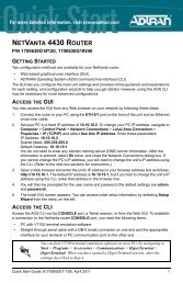
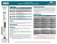
3. REVIEWING THE FRONT PANEL DESIGN<br />
The front panel contains the Alarm Cut-off switch (ACO), the CRAFT port, and the status LEDs for the<br />
system controller, the network modules, and the option modules. Figure 1 identifies the ACO switch, the<br />
CRAFT port, and the LEDs.<br />
Craft<br />
Port<br />
ACO Switch<br />
<strong>System</strong> Status ACO<br />
LEDs<br />
Switch<br />
Network<br />
Module LEDs<br />
Option Module LEDs<br />
Figure 1. <strong>ATLAS</strong> <strong>550</strong> Front Panel Layout<br />
Pressing the ACO switch deactivates (clears) the Alarm Relay, located on the back panel of the<br />
<strong>ATLAS</strong> <strong>550</strong>, after an alarm condition has occurred. If an alarm condition is corrected and then reoccurs,<br />
the Alarm Relay re-energizes.<br />
CRAFT Port (DB-9, female)<br />
Use the CRAFT port to configure the system via an EIA-232 connection. Table 1 on page 28 gives the<br />
CRAFT port pinout.<br />
61200305L2-1B © 2004 ADTRAN, Inc. 27
Section 2 Engineering Guidelines <strong>ATLAS</strong> <strong>550</strong> <strong>System</strong> <strong>Manual</strong><br />
Front Panel LEDs<br />
Table 1. CRAFT Port Pinout<br />
Pin Name Description<br />
1, 4, 6-9 —– Unused<br />
2 RD Receive Data (output)<br />
3 TD Transmit Data (input)<br />
5 SG Signal Ground<br />
With the <strong>ATLAS</strong> <strong>550</strong> powered-up, the front panel LEDs provide visual information about the status of the<br />
<strong>ATLAS</strong> <strong>550</strong> and any option modules that may be installed. Table 2 provides a brief description of the front<br />
panel features, and Table 3 on page 29 provides detailed information about the LEDs.<br />
Table 2. <strong>ATLAS</strong> <strong>550</strong> Front Panel Description<br />
Feature Description<br />
<strong>System</strong> Status LEDs Display the general status of the entire <strong>ATLAS</strong> <strong>550</strong> (see Table 3 on page 29).<br />
Power Indicates the unit is on or off.<br />
<strong>System</strong> Indicates the status of the system controller and other system conditions.<br />
Ethernet Indicates the status of the Ethernet port.<br />
Remote Indicates whether a user is logged into the unit.<br />
Network Module LEDs Display the status of the two network interfaces (see Table 3 on page 29). All<br />
LEDs are off if no network module is installed.<br />
OK Indicates that the network interface is operating correctly.<br />
Test Indicates that the network interface is in test mode.<br />
Error Blinks to indicate the occurrence of error events.<br />
Alarm Indicates an alarm condition on the network interface.<br />
Option Module LEDs Display (by row) the operational condition of each module installed in the<br />
option slots (see Table 3 on page 29). All LEDs will be off if no option module<br />
is installed.<br />
Status Indicates the operational condition of each of the modules installed in the four<br />
option slots.<br />
Online Indicates whether the module is available for use or is currently in use. If the<br />
module is manually taken offline, this LED is turned off.<br />
Test Indicates that one or more module ports are in test.<br />
ACO Switch When pressed, clears the Alarm Relay connection located on the back panel<br />
of the <strong>ATLAS</strong> <strong>550</strong>.<br />
CRAFT Port Connects the <strong>ATLAS</strong> <strong>550</strong> to a computer or modem.<br />
28 © 2004 ADTRAN, Inc. 61200305L2-1B
<strong>ATLAS</strong> <strong>550</strong> <strong>System</strong> <strong>Manual</strong> Section 2 Engineering Guidelines<br />
Table 3. Description of <strong>ATLAS</strong> <strong>550</strong> LEDs<br />
For these LEDs... This color light... Indicates that...<br />
<strong>System</strong> Status<br />
Power<br />
<strong>System</strong><br />
Ethernet<br />
Remote<br />
Network Modules Status<br />
Green the unit is on.<br />
Off the unit is off.<br />
Green (solid) no diagnosed system faults were found.<br />
Green (fast blink) a flash download is in progress.<br />
Yellow (solid)<br />
Red (solid)<br />
a fault was diagnosed, but the condition no longer exists.<br />
The condition will be recorded in the system log.<br />
an error condition with either the power supply or the<br />
system temperature is present.<br />
Red (fast blink) a fatal error occurred during flash download.<br />
Off power is not currently supplied to the system.<br />
Green (solid) the physical link is up.<br />
Green (flashing) there is activity on the LAN.<br />
Off the physical link is down - no Ethernet connection.<br />
Yellow<br />
OK Green (solid)<br />
Test Yellow (solid)<br />
Error Red (blink)<br />
Alarm Red (solid)<br />
a user is logged into the system via the ADMIN/CRAFT<br />
port or via the ETHERNET port.<br />
Off there are no users logged into the system.<br />
the network interface is operating normally with error-free<br />
operation. If the interface experiences alarms, the OK<br />
LED remains off.<br />
the interface is operating in a test mode. This includes a<br />
self-test, a test pattern, or a test loopback. When<br />
illuminated, this LED also indicates that normal data flow<br />
is not occurring on the module ports.<br />
an error such as BPV (bipolar violation), OOF (out of<br />
frame), or CRC (cyclic redundancy check) has occurred.<br />
an alarm condition has been detected. When the alarm<br />
condition is no longer valid, the OK LED illuminates. To<br />
view an alarm condition, select the active alarm menu<br />
item. If the alarm conditions have been corrected, you<br />
can view the alarm which caused the activation of the<br />
ALARM LED in the system log.<br />
61200305L2-1B © 2004 ADTRAN, Inc. 29
Section 2 Engineering Guidelines <strong>ATLAS</strong> <strong>550</strong> <strong>System</strong> <strong>Manual</strong><br />
Option Modules Status<br />
Status<br />
Online<br />
Table 3. Description of <strong>ATLAS</strong> <strong>550</strong> LEDs (Continued)<br />
For these LEDs... This color light... Indicates that...<br />
Green (solid)<br />
Green (fast blink)<br />
one or both modules (in the case of a Resource Module)<br />
are OK.<br />
one or both modules (in the case of a Resource Module)<br />
have been set offline by the user,<br />
OR<br />
one or both modules (in the case of a Resource Module)<br />
have invalid flash memory.<br />
Red (solid) a port on the installed module is currently in alarm.<br />
Red (fast blink)<br />
one module has no response, has been removed, or is<br />
not supported.<br />
Red (slow blink) one module is not ready.<br />
Off no module occupies the slot.<br />
Green (solid)<br />
Green (fast blink)<br />
one or both modules (in the case of a Resource Module)<br />
have an active connection.<br />
one module has invalid flash memory or is downloading<br />
firmware.<br />
Green (slow blink) one module has an active connection.<br />
Test Yellow (solid) one module is in a test mode.<br />
30 © 2004 ADTRAN, Inc. 61200305L2-1B
<strong>ATLAS</strong> <strong>550</strong> <strong>System</strong> <strong>Manual</strong> Section 2 Engineering Guidelines<br />
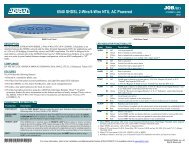
4. REVIEWING THE BACK PANEL DESIGN<br />
AC <strong>System</strong><br />
The <strong>ATLAS</strong> <strong>550</strong> (AC <strong>System</strong>) back panel contains four slots for housing option modules which provide a<br />
variety of additional resources and data ports. All slots are functionally identical. The <strong>ATLAS</strong> <strong>550</strong> also<br />
contains two slots for housing network modules (see Figure 2).<br />
ALL EMPTY SLOTS MUST BE<br />
COVERED WITH BLANK PANELS<br />
500 Series<br />
500 Series<br />
Figure 2. <strong>ATLAS</strong> <strong>550</strong> (AC <strong>System</strong>) Back Panel<br />
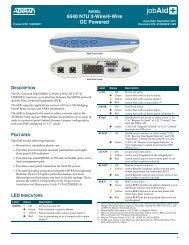
DC <strong>System</strong><br />
The <strong>ATLAS</strong> <strong>550</strong> (DC <strong>System</strong>) back panel contains four slots for housing option modules which provide a<br />
variety of additional resources and data ports. All slots are functionally identical. The <strong>ATLAS</strong> <strong>550</strong> also<br />
contains two slots for housing network modules (see Figure 3).<br />
ALL EMPTY SLOTS MUST BE<br />
COVERED WITH BLANK PANELS<br />
1<br />
2<br />
1<br />
2<br />
NETWORK 1<br />
NETWORK 1<br />
Option<br />
Module Slots<br />
500 Series<br />
3<br />
4<br />
NETWORK 2<br />
Figure 3. <strong>ATLAS</strong> <strong>550</strong> (DC <strong>System</strong>) Back Panel<br />
O I<br />
61200305L2-1B © 2004 ADTRAN, Inc. 31<br />
500 Series<br />
500 Series<br />
500 Series<br />
ADMIN<br />
Power<br />
Switch<br />
90-240VAC, 2A 50/60Hz<br />
FUSE RATING: 2A/250V SLO-BLO<br />
ETHERNET<br />
RELAY ALARM<br />
Network Module Slots ADMIN 10/100BaseT<br />
Port Ethernet<br />
Option<br />
Module Slots<br />
500 Series<br />
500 Series<br />
500 Series<br />
3<br />
4<br />
NETWORK 2<br />
500 Series<br />
Network Module Slots ADMIN<br />
Port<br />
500 Series<br />
500 Series<br />
ADMIN<br />
Power<br />
Switch<br />
MON NC NO COM<br />
O I<br />
+ Ð<br />
INPUT:<br />
FUSE:<br />
24Ð48V ,4A<br />
5A/48VDC<br />
USE COPPER CONDUCTORS ONLY<br />
ETHERNET<br />
RELAY ALARM<br />
10/100BaseT<br />
Ethernet<br />
MON NC NO COM<br />
CAUTION: FOR CONTINUED PROTECTION<br />
AGAINST RISK OF FIRE, REPLACE ONLY<br />
WITH SAME TYPE AND RATING OF FUSE.<br />
AC Power<br />
Connection<br />
Alarm<br />
Relay<br />
Connection<br />
External Alarm<br />
Relay Connection<br />
CAUTION: FOR CONTINUED PROTECTION<br />
AGAINST RISK OF FIRE, REPLACE ONLY<br />
WITH SAME TYPE AND RATING OF FUSE.<br />
DC Power<br />
Connection<br />
Alarm<br />
Relay<br />
Connection<br />
External Alarm<br />
Relay Connection
Section 2 Engineering Guidelines <strong>ATLAS</strong> <strong>550</strong> <strong>System</strong> <strong>Manual</strong><br />
ADMIN Port (USOC RJ-48C)<br />
The ADMIN port (EIA-232) connects to a computer or modem (see Table 4 for the pinout) and provides the<br />
following functions:<br />
• Accepts EIA-232 input from a PC or a modem for controlling the <strong>ATLAS</strong> <strong>550</strong>.<br />
• Operates at 2400, 9600, 19200, or 38400 bps.<br />
• Acts as input for either VT100 or PC control.<br />
• Acts as an interface for flash memory software downloads using XMODEM.<br />
Ethernet Connection (USOC RJ-48C)<br />
Table 4. ADMIN Port Pinout<br />
Pin Name Description<br />
1 SG Signal Ground<br />
2 RTS Request to Send (output), follows CTS<br />
3 TD Transmit Data (input)<br />
4 DTR Data Terminal Ready (output), +12 V<br />
5 RD Receive Data (output)<br />
6 DCD Data Carrier Detect (input)<br />
7 —– Not Connected<br />
8 CTS Clear to Send (input)<br />
The ETHERNET port (RJ-48C) provides a 10/100BaseT ETHERNET LAN connection, which is used for<br />
IP routing, TFTP, SNMP, and Telnet connections. Table 5 shows the pinout.<br />
Table 5. Ethernet Pinout<br />
Pin Name Description<br />
1 TX1 Transmit Positive<br />
2 TX2 Transmit Negative<br />
3 RX1 Receive Positive<br />
4, 5 —– Unused<br />
6 RX2 Receive Negative<br />
7, 8 —– Unused<br />
32 © 2004 ADTRAN, Inc. 61200305L2-1B
<strong>ATLAS</strong> <strong>550</strong> <strong>System</strong> <strong>Manual</strong> Section 2 Engineering Guidelines<br />
External Alarm Relay Monitor Connection<br />
This connection alerts the user when a selected external alarm condition exists. This connection could be<br />
used to monitor a UPS with dry contacts or another <strong>ATLAS</strong> <strong>550</strong>. The 2-pin, removable terminal block<br />
connects with external wiring. Refer to DLP-14, Connecting the Alarm Contacts, for detailed instructions.<br />
Clear the alarm condition by pressing the ACO switch located on the front panel of the <strong>ATLAS</strong> <strong>550</strong>.<br />
Table 6 shows the pinout for the External Alarm Relay connector.<br />
Alarm Relay Connection<br />
Table 6. External Relay Monitor Connector Pinout<br />
Pin Name Description<br />
1 ALARM OUT Outputs EIA-232 level signal for connection to external alarm contacts.<br />
2 ALARM IN Monitors signal coming from external alarm contacts.<br />
This connection alerts the user when a selected alarm condition exists. The 4-pin, removable terminal<br />
block connects with external wiring. Refer to DLP-14, Connecting the Alarm Contacts, for detailed<br />
instructions. Clear the alarm condition by pressing the ACO switch located on the front panel of the<br />
<strong>ATLAS</strong> <strong>550</strong>. Table 7 shows the pinout for the Alarm Relay connector.<br />
Table 7. Alarm Relay Connector Pinout<br />
Pin Name Description<br />
1 NORMALLY CLOSED (NC) Opens when a selected alarm condition is present.<br />
2 NORMALLY OPEN (NO) Closes when a selected alarm condition is present.<br />
3 COMMON (COM)<br />
4 CHASSIS GROUND (GND) Ground connection.<br />
Common connection between external circuitry and NC or NO<br />
terminal.<br />
5. NETWORK INTERFACE MODULES<br />
The <strong>ATLAS</strong> <strong>550</strong> provides two Network Interface Slots that allow different types of interfaces to be used.<br />
Available Network Interface Modules include the following:<br />
• T1/PRI Network Interface Module (P/N 1200307L1/L2), USOC RJ-48C. (See page 34.)<br />
• E1/PRA Network Interface Module (P/N 1200308L1), 15-pin female D-connector. (See page 34.)<br />
• Modem Management Network Module (P/N 1200341L1), USOC RJ-11C. (See page 35.)<br />
• BRI DBU Network Module (P/N 1200327L1), USOC RJ-49C. (See page 36.)<br />
61200305L2-1B © 2004 ADTRAN, Inc. 33
Section 2 Engineering Guidelines <strong>ATLAS</strong> <strong>550</strong> <strong>System</strong> <strong>Manual</strong><br />
T1/PRI Network Interface Module (P/N 1200307L1/L2), USOC RJ-48C<br />
The T1/PRI Network Interface Module provides a single T1/PRI port (see Table 8 for the pinout) and<br />
complies with the applicable ANSI and AT&T ® standards. The T1/PRI Network Interface Module<br />
provides the following functions:<br />
• AMI or B8ZS coding<br />
• <strong>Manual</strong> line build-out<br />
• D4 or ESF framing<br />
• Network performance monitoring and reporting<br />
• Test loopbacks with QRSS generation and checking<br />
• Extensive self-testing<br />
Test Interface<br />
The MON IN and OUT Bantam test jacks provide a bridged access jack for nonintrusive monitoring of the<br />
incoming T1. When connected to this jack, configure the test equipment for bridged termination.<br />
E1/PRA Network Interface Module (P/N 1200308L1), 15-pin female D-connector<br />
The E1/PRA Network Interface Module provides a single E1/PRA port (see Table 9 on page 35) that provide<br />
the following functions:<br />
• AMI or HDB3 coding<br />
• <strong>Manual</strong> line build-out<br />
• NFAS, FAS, TS16 MF and CRC-4 framing<br />
• Supports CCS or CAS signaling<br />
• Network performance monitoring and reporting<br />
• Test loopbacks with QRSS generation and checking<br />
• Extensive self-testing<br />
Table 8. T1/PRI Network Interface Module RJ-48C Pinout<br />
Pin Name Description<br />
1 RXDATA-RING (R1) Receive data from the network<br />
2 RXDATA-TIP (T1) Receive data from the network<br />
3 ––––– Unused<br />
4 TXDATA-RING (R) Transmit data toward the network<br />
5 TXDATA-TIP (T) Transmit data toward the network<br />
6, 7, 8 ––––– Unused<br />
34 © 2004 ADTRAN, Inc. 61200305L2-1B
<strong>ATLAS</strong> <strong>550</strong> <strong>System</strong> <strong>Manual</strong> Section 2 Engineering Guidelines<br />
Table 9. E1/PRA Network Interface 15-pin Female D-connector Pinout<br />
Pin Name Description<br />
1 TXDATA-RING (R) Transmit data toward the network<br />
2,4,5,7 FRAME GROUND (FG) Grounded to chassis<br />
3 RXDATA-RING (R1) Receive data from the network<br />
6,8,10,12-15 –––––– Unused<br />
9 TXDATA-TIP (T) Transmit data toward the network<br />
11 RXDATA-TIP (T1) Receive data from the network<br />
Test Interface<br />
This module contains two test interfaces: NETWORK and MON. The NETWORK IN and OUT Bantam test<br />
jacks provide intrusive test capability for the incoming E1. By connecting test equipment to these jacks, the<br />
E1 connection breaks and the test equipment terminates the incoming E1. The MON IN and OUT Bantam<br />
test jacks provide a bridged access jack for nonintrusive monitoring of the incoming E1. When connected<br />
to this jack, configure the test equipment for bridged termination.<br />
Modem Management Network Module (P/N 1200341L1), USOC RJ-11C<br />
The Modem Management Network Module provides a single 6-pin modular jack (RJ-11C) (see Table 10<br />
for the pinout). The Modem Management Network Module provides the following functions:<br />
• V.34, V.32bis, V.32, V.22, V.23, and V.21 data modulation schemes<br />
• Connection rates from 2400 to 33.6K baud<br />
• V.42 LAPM, MNP 2-4, and MNP 10 error correction methods<br />
• V.42bis and MNP 5 data compression algorithms<br />
Table 10. Modem Management Network Module RJ-11C Pinout<br />
Pin Name Description<br />
1, 2, 5, 6 ––– Unused<br />
3 TIP Tip to and from the analog interface<br />
4 RING Ring to and from the analog interface<br />
61200305L2-1B © 2004 ADTRAN, Inc. 35
Section 2 Engineering Guidelines <strong>ATLAS</strong> <strong>550</strong> <strong>System</strong> <strong>Manual</strong><br />
BRI DBU Network Module (P/N 1200327L1), USOC RJ-49C<br />
The BRI DBU Network Module provides a single 8-pin jack (RJ-49C) for connection to a standard BRI U interface<br />
circuit. All BONDing functionality for 2B+D operation is provided on the module. Table 11 shows the<br />
pinout for this connection.<br />
6. OPTION MODULE INTERFACES<br />
Table 11. BRI DBU Network Module RJ-49C Pinout<br />
Pin Name Description<br />
1, 2, 3, 6, 7, 8 –––– Unused<br />
4 RING Ring to and from the network interface<br />
5 TIP Tip to and from the network interface<br />
The <strong>ATLAS</strong> <strong>550</strong> contains four option slots that hold a variety of modules. This sections provides a brief<br />
description of these modules and their pinouts, as follows:<br />
• Octal/Quad FXS Option Module (P/N 1200309L1/1200328L1), 8-Pin Modular Jack. (See page 36.)<br />
• Octal/Quad FXO Option Module (P/N 1200310L1/1200329L1), 8-Pin Modular Jack. (See page 37.)<br />
• Dual Nx 56/64 Option Module (P/N 1200311L1), V.35 Winchester. (See page 37.)<br />
• Dual USSI Option Module (P/N 1200754L1), DB-78. (See page 38.)<br />
• Octal E&M Option Module (P/N 1200313L1), 8-Pin Modular Jack. (See page 42.)<br />
• Dual/Quad T1/PRI Option Module (P/N 1200314L1/L2 and 1200755L1/L2), USOC RJ-48C. (See page 43.)<br />
• Quad BRI (U-Interface) Option Module (P/N 1200315L1), USOC RJ-48C. (See page 43.)<br />
• Quad BRI ISDN (S/T Interface) Option Module (P/N 1200764L1), USOC RJ-45. (See page 43.)<br />
• NxT1 HSSI Option Module (P/N 1200346L1), 50-Pin SCSI-II. (See page 44.)<br />
• NxT1 HSSI/V.35 Option Module (P/N 1200346L2). (See page 44.)<br />
• Legacy Data Option Module (P/N 1200342L1), EIA-232 and V.35. (See page 46.)<br />
• Octal Ethernet Switch Option Module (P/N 1200766L1), USOC RJ-48C. (See page 47.)<br />
Octal/Quad FXS Option Module (P/N 1200309L1/1200328L1), 8-Pin Modular Jack<br />
Each port of the Octal/Quad FXS Option Module has a single 8-pin modular jack. Table 12 shows the pinout.<br />
Table 12. FXS 8-Pin Modular Jack Pinout<br />
Pin Name Description<br />
1, 2, 3, 6, 7, 8 –––– Unused<br />
4 RING Ring to and from the analog phone interface<br />
5 TIP Tip to and from the analog phone interface<br />
36 © 2004 ADTRAN, Inc. 61200305L2-1B
<strong>ATLAS</strong> <strong>550</strong> <strong>System</strong> <strong>Manual</strong> Section 2 Engineering Guidelines<br />
Octal/Quad FXO Option Module (P/N 1200310L1/1200329L1), 8-Pin Modular Jack<br />
Each port of the Octal/Quad FXO Option Module has a single 8-pin modular jack. Table 13 shows the<br />
pinout.<br />
Table 13. FXO 8-Pin Modular Jack Pinout<br />
Pin Name Description<br />
1, 2, 3, 6, 7, 8 –––– Unused<br />
4 RING Ring to and from the analog phone interface<br />
5 TIP Tip to and from the analog phone interface<br />
Dual Nx 56/64 Option Module (P/N 1200311L1), V.35 Winchester<br />
Each port of the Dual Nx 56/64 Option Module has a V.35 Winchester-style connection as defined in<br />
Table 14.<br />
Table 14. V.35 Winchester Pinout<br />
Pin CCITT Description<br />
A 101 Protective ground (PG)<br />
B 102 Signal ground (SG)<br />
C 105 Request to send (RTS) from DTE<br />
D 106 Clear to send (CTS) to DTE<br />
E 107 Data set ready (DSR) to DTE<br />
F 109 Received line signal detector (DCD) to DTE<br />
H — Data terminal ready (DTR) from DTE<br />
J — Ring indicator (RI)<br />
R 104 Received data (RD-A) to DTE<br />
T 104 Received data (RD-B) to DTE<br />
V 115 RX clock (RC-A) to DTE<br />
X 115 RX clock (RC-B) to DTE<br />
P 103 Transmitted data (TD-A) from DTE<br />
S 103 Transmitted data (TD-B) from DTE<br />
Y 114 TX clock (TC-A) to DTE<br />
AA 114 TX clock (TC-B) to DTE<br />
U 113 External TX clock (ETC-A) from DTE<br />
W 113 External TX clock (ETC-B) from DTE<br />
NN — Test mode (TM) to DTE<br />
61200305L2-1B © 2004 ADTRAN, Inc. 37
Section 2 Engineering Guidelines <strong>ATLAS</strong> <strong>550</strong> <strong>System</strong> <strong>Manual</strong><br />
Dual USSI Option Module (P/N 1200754L1), DB-78<br />
Tables 15 through 20 show pinouts for the available interfaces of the Dual USSI Option Module and the<br />
system part numbers required for ordering.<br />
Table 15. DB-78 Connector Pinout<br />
Pin Signal Description Pin Signal Description<br />
1 RXD-A 2 42 GND<br />
2 RXD-B 2 43—48 UNUSED<br />
3 RXC-A 2 49 MOD2<br />
4 RXC-B 2 50 MOD0<br />
5 TXD-A 2 51 EXT-TXC-A 1<br />
6 TXD-B 2 52 DTR-B 1<br />
7 TXC-A 2 53 DTR-A 1<br />
8 TXC-B 2 54 DCD-B 1<br />
9 EXT-TXC-A 2 55 DCD-A 1<br />
10 EXT-TXC-B 2 56 DSR-B/RI 1<br />
11—17 UNUSED 57 DSR-A 1<br />
18 GND 58 CTS-B 1<br />
19 GND 59 CTS-A 1<br />
20 CHASIS GND 60 CHASIS GND<br />
21 CTS-A 2 61 GND<br />
22 CST-B 2 62—68 UNUSED<br />
23 DSR-A 2 69 MOD1<br />
24 DSR-B/RI 2 70 EXT-TXC-B 1<br />
25 DCD-A 2 71 TXC-B 1<br />
26 DCD-B 2 72 TXC-A 1<br />
27 DTR-A 2 73 TXD-B 1<br />
28 DTR-B 2 74 TXD-A 1<br />
29—37 UNUSED 75 RXC-B 1<br />
38 RTS-A 1 76 RXC-A 1<br />
39 RTS-B 1 77 RXD-B 1<br />
40 RTS-A 2 78 RXD-A 1<br />
41 RTS-B 2<br />
Note: A signal description followed by a 1 or a 2 indicates the port on the USSI<br />
Module.<br />
38 © 2004 ADTRAN, Inc. 61200305L2-1B
<strong>ATLAS</strong> <strong>550</strong> <strong>System</strong> <strong>Manual</strong> Section 2 Engineering Guidelines<br />
Table 16. EIA-530 Connector Pinout (<strong>System</strong> P/N 4200754L2)<br />
Pin Signal Description Pin Signal Description<br />
1 Shield (Ground) 14 Transmit Data (B)<br />
2 Transmit Data (A) 15 Transmit Clock (A)<br />
3 Received Data (A) 16 Received Data (B)<br />
4 Request to Send (A) 17 Receive Clock (A)<br />
5 Clear to Send (A) 18 Local Loopback *<br />
6 DCE Ready (A) 19 Request to Send (B)<br />
7 Signal Ground 20 DTE Ready (A)<br />
8 Carrier Detect (A) 21 Remote Loopback *<br />
9 Received Clock (B) 22 DCE Ready (B)<br />
10 Carrier Detect (B) 23 DTE Ready (B)<br />
11 Ext. Transmit Clock (B) 24 Ext. Transmit Clock (A)<br />
12 Transmit Clock (B) 25 Test Mode *<br />
13 Clear to Send (B)<br />
Asterisk (*) indicates that this pin is ignored by Dual USSI Module.<br />
Table 17. EIA-530A Connector Pinout (<strong>System</strong> P/N 4200754L2)<br />
Pin Signal Description Pin Signal Description<br />
1 Shield (Ground) 14 Transmit Data (B)<br />
2 Transmit Data (A) 15 Transmit Clock (A)<br />
3 Received Data (A) 16 Received Data (B)<br />
4 Request to Send (A) 17 Receive Clock (A)<br />
5 Clear to Send (A) 18 Local Loopback *<br />
6 DCE Ready (A) 19 Request to Send (B)<br />
7 Signal Ground 20 DTE Ready (A)<br />
8 Carrier Detect (A) 21 Remote Loopback *<br />
9 Received Clock (B) 22 Ring Indicator<br />
10 Carrier Detect (B) 23 Signal Ground<br />
11 Ext. Transmit Clock (B) 24 Ext. Transmit Clock (A)<br />
12 Transmit Clock (B) 25 Test Mode *<br />
13 Clear to Send (B)<br />
Asterisk (*) indicates that this pin is ignored by Dual USSI Module.<br />
61200305L2-1B © 2004 ADTRAN, Inc. 39
Section 2 Engineering Guidelines <strong>ATLAS</strong> <strong>550</strong> <strong>System</strong> <strong>Manual</strong><br />
Table 18. RS-449/V.36 Connector Pinout (P/N 4200754L1)<br />
Pin Signal Description Pin Signal Description<br />
1 Shield (Ground) 20 Receive Common *<br />
2 Signaling Rate Indicator * 21 Unused<br />
3 Unused 22 Transmit Data (B)<br />
4 Transmit Data (A) 23 Transmit Clock (B)<br />
5 Transmit Clock (A) 24 Receive Data (B)<br />
6 Received Data (A) 25 Request to Send (B)<br />
7 Request to Send (A) 26 Receive Clock (B)<br />
8 Receive Clock (A) 27 Clear to Send (B)<br />
9 Clear to Send (A) 28 Terminal in Service *<br />
10 Local Loopback * 29 DCE Ready (B)<br />
11 DCE Ready (A) 30 DTE Ready (B)<br />
12 DTE Ready (A) 31 Carrier Detect (B)<br />
13 Carrier Detect (A) 32 Select Standby *<br />
14 Remote Loopback * 33 Signal Quality *<br />
15 Ring Indicator 34 New Signal *<br />
16 Select Frequency * 35 Ext. Transmit Clock (B)<br />
17 Ext. Transmit Clock (A) 36 Standby/Indicator *<br />
18 Test Mode * 37 Send Common *<br />
19 Signal Ground<br />
Asterisk (*) indicates that this pin is ignored by Dual USSI Module.<br />
40 © 2004 ADTRAN, Inc. 61200305L2-1B
<strong>ATLAS</strong> <strong>550</strong> <strong>System</strong> <strong>Manual</strong> Section 2 Engineering Guidelines<br />
Table 19. RS-232 Connector Pinout (P/N 4200754L4)<br />
Pin Signal Description Pin Signal Description<br />
1 Shield (Ground) 14 Sec. Transmit Data<br />
2 Transmit Data 15 DCE Transmit Clock<br />
3 Received Data 16 Sec. Received Data<br />
4 Request to Send 17 Receive Signal Element Timing<br />
5 Clear to Send 18 Unused<br />
6 Data Set Ready 19 Sec. Request to Send<br />
7 Signal Ground 20 Data Terminal Ready<br />
8 Received Line Signal Detector 21 Signal Quality Detector *<br />
9 + Voltage * 22 Ring Indicator<br />
10 - Voltage * 23 Data Signal Rate Selector *<br />
11 Unused 24 DTE Transmit Clock<br />
12 Sec. Received LIne Signal Indicator 25 Unused<br />
13 Sec. Clear to Send<br />
Asterisk (*) indicates that this pin is ignored by Dual USSI Module.<br />
Table 20. CCITT X.21/V.11 Connector Pinout (P/N 4200754L3)<br />
Pin Signal Description Pin Signal Description<br />
1 Shield (Ground) 9 Transmit Data (B)<br />
2 Transmit Data (A) 10 Request to Send (B)<br />
3 Request to Send (A) 11 Received Data (B)<br />
4 Received Data (A) 12 Carrier Detect (B)<br />
5 Carrier Detect (A) 13 Transmit/Received Clock (B)<br />
6 Transmit/Receive Clock (A) 14 Ext. Transmit Clock (B)<br />
7 Ext. Transmit Clock (A) 15 Unused<br />
8 Signal Ground<br />
61200305L2-1B © 2004 ADTRAN, Inc. 41
Section 2 Engineering Guidelines <strong>ATLAS</strong> <strong>550</strong> <strong>System</strong> <strong>Manual</strong><br />
Octal E&M Option Module (P/N 1200313L1), 8-Pin Modular Jack<br />
Each port of the Octal E&M Option Module has a single 8-pin modular jack. The Octal E&M module is an<br />
E-lead originate signaling circuit suitable for connection to an M-lead originate trunk circuit. Table 21<br />
shows the pinout, and Table 22 shows the E&M signaling types.<br />
Table 21. E&M 8-Pin Modular Jack Pinout<br />
PIN Name Description<br />
1 Ring VF input (4W mode, 600 Ω nominal)<br />
2 Tip<br />
3 E Customer Originate<br />
4 SG Signal Ground<br />
5 SB Signal Battery<br />
6 M Network Originate<br />
7 Tip 1<br />
8 Ring 1<br />
Tip/Ring (2W mode, 600 Ω + 2.16 µF nominal)<br />
VF output (4W mode, 600 Ω nominal)<br />
Table 22. Trunk Circuit Connections for Various E&M Signaling Types<br />
Signaling<br />
Type<br />
Trunk Circuit Connections<br />
E M SG SB<br />
Type I Pin 3 Pin 6 NC NC<br />
Type II Pin 3 Pin 6 Pin 4 Pin 5<br />
Type III Pin 3 Pin 6 Pin 4 Pin 5<br />
Type IV Pin 3 Pin 6 Pin 4 Use Frame Ground<br />
Type V Pin 3 Pin 6 NC NC<br />
42 © 2004 ADTRAN, Inc. 61200305L2-1B
<strong>ATLAS</strong> <strong>550</strong> <strong>System</strong> <strong>Manual</strong> Section 2 Engineering Guidelines<br />
Dual/Quad T1/PRI Option Module (P/N 1200314L1/L2 and 1200755L1/L2),<br />
USOC RJ-48C<br />
Each port of the Dual/Quad T1/PRI Option Module uses a single, 8-position modular jack for connection<br />
to the T1 or PRI circuit. Table 23 gives the pinout for this jack.<br />
Table 23. T1/PRI RJ-48C Pinout<br />
Pin Name Description<br />
1 RXDATA-RING (R) Receive data from the network<br />
2 RXDATA-TIP (T1) Receive data from the network<br />
3 ––––– Unused<br />
4 TXDATA-RING (R) Send data towards the network<br />
5 TXDATA-TIP (T) Send data towards the network<br />
6,7,8 ––––– Unused<br />
Quad BRI (U-Interface) Option Module (P/N 1200315L1), USOC RJ-48C<br />
Each port of the Quad BRI (U-Interface) Option Module uses a single RJ-48C jack for connection to a<br />
standard BRI U-interface circuit. Table 24 shows the network pinout connection.<br />
Table 24. BRI RJ-48C Pinout (U-Interface)<br />
Pin Name Description<br />
1, 2, 3, 6, 7, 8 ––– Unused<br />
4 RING Ring to and from the network interface<br />
5 TIP Tip to and from the network interface<br />
Quad BRI ISDN (S/T Interface) Option Module (P/N 1200764L1), USOC RJ-45<br />
Each port of the Quad BRI ISDN (S/T Interface) Option Module uses a single RJ-45 jack for connection to<br />
a standard BRI S/T interface circuit. The Quad BRI ISDN (S/T Interface) Option Module is only available<br />
for use in NT mode (User Term) applications. Table 25 shows the network pinout connection.<br />
Table 25. BRI RJ-48C Pinout (S/T Interface)<br />
Pin Name Description<br />
1, 2, 7, 8 ––– Unused<br />
3, 6 RECEIVE Receive for User Term (NT Mode)<br />
4, 5 TRANSMIT Transmit for User Term (NT Mode)<br />
61200305L2-1B © 2004 ADTRAN, Inc. 43
Section 2 Engineering Guidelines <strong>ATLAS</strong> <strong>550</strong> <strong>System</strong> <strong>Manual</strong><br />
NxT1 HSSI Option Module (P/N 1200346L1), 50-Pin SCSI-II<br />
The NxT1 HSSI Option Module uses a single 50-pin SCSI-II interface to combine up to eight T1s of data<br />
(four from the NxT1 HSSI Module T1 ports and four from other T1 ports installed in the system). Table 26<br />
gives the pinouts for the SCSI-II connector, and Table 28 on page 45 gives the pinouts for the RJ-48C (T1)<br />
connector.<br />
Pin #<br />
(+ side)<br />
Pin #<br />
(- side)<br />
Table 26. HSSI (SCSI-II, 50-Pin) Connection Pinout<br />
Description<br />
Pin #<br />
(+ side)<br />
NxT1 HSSI/V.35 Option Module (P/N 1200346L2)<br />
Pin #<br />
(- side)<br />
Description<br />
1 26 SG - Signal Ground 10 35 LA - Loopback Circuit A<br />
2 27 RT - Receive Timing 11 36 SD - Send Data<br />
3 28 CA - DCE Available 12 37 LB - Loopback Circuit B<br />
4 29 RD - Receive Data 13 38 SG - Signal Ground<br />
5 30 LC - Loopback Circuit C 14-18 39-43 Ancillary to DCE (Reserved)<br />
6 31 ST - Send Timing 19 44 SG - Signal Ground<br />
7 32 SG - Signal Ground 20-23 45-48 Ancillary to DTE (Reserved)<br />
8 33 TA - DTE Available 24 49 TM - Test Mode<br />
9 34 TT - Terminal Timing 25 50 SG - Signal Ground<br />
V.35 is possible with the NxT1 HSSI Option Module with an appropriate adapter cable (ADTRAN<br />
P/N 3125I081@A); however, some HSSI menu options will be unavailable in this mode (for details, see<br />
the User Interface Guide section). Table 27 and Table 28 on page 45 give the pinouts for the V.35 and<br />
RJ-48C (T1) connectors, respectively.<br />
Pin#<br />
(+ side)<br />
Table 27. HSSI/V.35 Connection Pinout<br />
Pin#<br />
(- side)<br />
Direction Description<br />
1 26 — HSSI SG - Signal Ground<br />
2 27 O HSSI RT - Receive Timing<br />
3 28 O HSSI CA - DCE Available<br />
4 29 O HSSI RD - Receive Data<br />
5 30 O HSSI LC - Loopback Circuit C<br />
6 31 O HSSI ST - Send Timing<br />
7 32 — HSSI SG - Signal Ground<br />
8 33 I HSSI TA - DTE Available<br />
9 34 I HSSI TT - Terminal Timing<br />
10 35 I HSSI LA - Loopback Circuit A<br />
44 © 2004 ADTRAN, Inc. 61200305L2-1B
<strong>ATLAS</strong> <strong>550</strong> <strong>System</strong> <strong>Manual</strong> Section 2 Engineering Guidelines<br />
Pin#<br />
(+ side)<br />
Table 27. HSSI/V.35 Connection Pinout (Continued)<br />
Pin#<br />
(- side)<br />
Direction Description<br />
11 36 I HSSI SD - Send Data<br />
12 37 I HSSI LB - Loopback Circuit B<br />
13 38 — HSSI SG - Signal Ground<br />
— 39 — Ancillary to DCE (Reserved)<br />
14 — I V.35 RTS - Request to Send<br />
15 40 I V.35 TT Terminal Timing<br />
16 41 I V.35 SD Send Data<br />
— 42 O V.35 DCD - Data Carrier Detect<br />
17-18 43 — Ancillary to DCE (Reserved)<br />
19 44 — HSSI SG - Signal Ground<br />
20 45 O V.35 ST - Send Timing<br />
21 46 O V.35 - Receive Timing<br />
22 47 O V.35 RD - Receive Data<br />
23 — O V.35 CTS - Clear to Send<br />
— 48 I V.35 Ground/Present<br />
24 49 O TM - Test Mode<br />
25 50 — SG - Signal Ground<br />
Table 28. T1 Network Connection Pinout<br />
Pin Name Description<br />
1 RXDATA-RING (R1) Receive data from the network<br />
2 RXDATA-TIP (T1) Receive data from the network<br />
4 TXDATA-RING (R) Send data towards the network<br />
5 TXDATA-TIP (T) Send data towards the network<br />
3,6,7,8 ––––– Unused<br />
61200305L2-1B © 2004 ADTRAN, Inc. 45
Section 2 Engineering Guidelines <strong>ATLAS</strong> <strong>550</strong> <strong>System</strong> <strong>Manual</strong><br />
Legacy Data Option Module (P/N 1200342L1), EIA-232 and V.35<br />
The Legacy Data Option Module provides four EIA-232 or V.35 interfaces (or any combination up to four)<br />
for synchronous or asynchronous packet data applications. Table 29 gives the pinouts for both the EIA-232<br />
and V.35 connections.<br />
Table 29. EIA-232 and V.35 Connection Pinouts<br />
EIA-232 Pin V.35 Pin CCITT/V.24 Pin Description<br />
–– A 101 Protective ground (PG)<br />
7 B 102 Signal ground (SG)<br />
4 C 105 Request to send (RTS) from DTE<br />
5 D 106 Clear to send (CTS) to DTE<br />
6 E 107 Data set ready (DSR) to DTE<br />
8 F 109 Received line signal detector (DCD) to DTE<br />
20 H 108/2 Data terminal ready (DTR) from DTE<br />
22 J 125 Ring indicator (RI) to DTE<br />
3 R 104 Received data (RD-A) to DTE<br />
3 T 104 Received data (RD-B) to DTE<br />
17 V 115 RX clock (RC-A) to DTE<br />
17 X 115 RX clock (RC-B) to DTE<br />
2 P 103 Transmitted data (TD-A) from DTE<br />
2 S 103 Transmitted data (TD-B) from DTE<br />
15 Y 114 TX clock (TC-A) to DTE<br />
15 AA 114 TX clock (TC-B) to DTE<br />
24 U 113 External TX clock (ETC-A) from DTE<br />
24 W 113 External TX clock (ETC-B) from DTE<br />
–– NN 142 Test mode (TM) to DTE<br />
46 © 2004 ADTRAN, Inc. 61200305L2-1B
<strong>ATLAS</strong> <strong>550</strong> <strong>System</strong> <strong>Manual</strong> Section 2 Engineering Guidelines<br />
Octal Ethernet Switch Option Module (P/N 1200766L1), USOC RJ-48C<br />
The Octal Ethernet Switch Option Module provides eight RJ-48C interfaces that can operate as 10BaseT or<br />
100BaseTX. Table 30 gives the pinout for the Ethernet connection.<br />
Table 30. Ethernet RJ-48C Pinout<br />
Pin Name Description<br />
1 TX1 Transmit Positive<br />
2 TX2 Transmit Negative<br />
3 RX1 Receive Positive<br />
4, 5 –––– Unused<br />
6 RX2 Receive Negative<br />
7, 8 –––– Unused<br />
61200305L2-1B © 2004 ADTRAN, Inc. 47
Section 2 Engineering Guidelines <strong>ATLAS</strong> <strong>550</strong> <strong>System</strong> <strong>Manual</strong><br />
7. AT-A-GLANCE SPECIFICATIONS<br />
Table 31 lists the specifications for the <strong>ATLAS</strong> <strong>550</strong> system.<br />
Table 31. <strong>ATLAS</strong> <strong>550</strong> <strong>System</strong> Specifications<br />
Application Feature Specification<br />
TDM Applications<br />
Switching Applications<br />
TDM bandwidth 14 Mbps, Full duplex<br />
Dedicated map connections 160 Dedicated map connections in each of the<br />
five maps; one active map at a time<br />
ISDN signaling types National ISDN<br />
Lucent 5E<br />
AT&T 4ESS (PRI Only)<br />
Northern DMS-100 (Nortel Custom)<br />
EuroISDN<br />
T1 signaling types Loop-Start<br />
Ground-Start<br />
E&M Wink<br />
E&M Immediate<br />
Feature Group D<br />
DSP Features DTMF tones support<br />
FSK Caller ID support<br />
Progress tone generation<br />
32 available DSP channels<br />
BRI Connections 17 BRI connections<br />
PRI Connections 10 PRI connections<br />
RBS T1 Connections 10 RBS T1 connections<br />
48 © 2004 ADTRAN, Inc. 61200305L2-1B
<strong>ATLAS</strong> <strong>550</strong> <strong>System</strong> <strong>Manual</strong> Section 2 Engineering Guidelines<br />
Frame Relay<br />
PPP<br />
IP Routing<br />
Table 31. <strong>ATLAS</strong> <strong>550</strong> <strong>System</strong> Specifications (Continued)<br />
Application Feature Specification<br />
Packet throughput 4000 pkts/sec (minimum)<br />
Management signaling<br />
interfaces<br />
UNI (user and network)<br />
NNI<br />
Management signaling types ANSI T1.617-D (Annex D)<br />
ITU-T Q.933-A (Annex A)<br />
LMI (Group of four)<br />
Auto<br />
Encapsulation RFC 1490<br />
PVC support 300 PVCs<br />
Congestion control FECN / BECN<br />
Discard eligible (DE)<br />
Quality of service (QOS) Prioritization on a per-PVC basis<br />
Testing (ADTRAN proprietary) PVC loopback<br />
Round trip delay measurement<br />
SNMP support RFC 1315<br />
Connection support 100 connections<br />
Authentication support PAP<br />
CHAP<br />
EAP<br />
Keepalive support On/Off<br />
Interface support Numbered interfaces<br />
Unnumbered interfaces<br />
Route discovery RIP V1<br />
RIP V2<br />
ICMP<br />
ARP<br />
IARP<br />
UDP Relay<br />
SNMP support RFCs 1155-SMI, 1158-MIB, 1212, 1213, 1215,<br />
1315, 1406<br />
ADTRAN Enterprise MIBs<br />
61200305L2-1B © 2004 ADTRAN, Inc. 49
Section 2 Engineering Guidelines <strong>ATLAS</strong> <strong>550</strong> <strong>System</strong> <strong>Manual</strong><br />
Voice Compression<br />
Table 31. <strong>ATLAS</strong> <strong>550</strong> <strong>System</strong> Specifications (Continued)<br />
Application Feature Specification<br />
Algorithm Voice Compression Module G.723.1 or<br />
Netcoder (proprietary)<br />
ADPCM-32 Module: G.711, G.726 (16K/32K),<br />
Transparent (proprietary)<br />
Number of channels Up to 32 compression channels<br />
PCM coding µ-Law<br />
Fax support 9600 bps<br />
Modem Support<br />
(ADPCM-32 Module only)<br />
The rates shown at the right are<br />
maximum rates. Under certain<br />
conditions, these rates may not<br />
be realized.<br />
DTMF generation and<br />
detection<br />
G.711, Transparent ADPCM 32<br />
V.34 @ 28.8 bps V.32 @ 14.4 bps<br />
FAX @ 14.4 bps FAX @ 14.4 bps<br />
ADPCM 16<br />
V.21 @ 300 bps<br />
V.22 @ 1200 bps<br />
FAX NOT RECOMMENDED<br />
TIA 464A<br />
50 © 2004 ADTRAN, Inc. 61200305L2-1B
NETWORK TURNUP PROCEDURE<br />
Provides shipment contents list, grounding instructions, mounting options, and specifics of supplying<br />
power to the unit.<br />
CONTENTS<br />
Introduction . . . . . . . . . . . . . . . . . . . . . . . . . . . . . . . . . . . . . . . . . . . . . . . . . . . . . . . . . . . . . . . . . . . .50<br />
Tools Required . . . . . . . . . . . . . . . . . . . . . . . . . . . . . . . . . . . . . . . . . . . . . . . . . . . . . . . . . . . . . . . . . 50<br />
Unpack and Inspect the <strong>System</strong> . . . . . . . . . . . . . . . . . . . . . . . . . . . . . . . . . . . . . . . . . . . . . . . . . . . 50<br />
Contents of ADTRAN Shipments . . . . . . . . . . . . . . . . . . . . . . . . . . . . . . . . . . . . . . . . . . . . . . . . 50<br />
Grounding Instructions . . . . . . . . . . . . . . . . . . . . . . . . . . . . . . . . . . . . . . . . . . . . . . . . . . . . . . . . . . 51<br />
Supplying Power to the Unit . . . . . . . . . . . . . . . . . . . . . . . . . . . . . . . . . . . . . . . . . . . . . . . . . . . . . . 51<br />
AC-Powered <strong>System</strong>s. . . . . . . . . . . . . . . . . . . . . . . . . . . . . . . . . . . . . . . . . . . . . . . . . . . . . . . . . 51<br />
DC-Powered <strong>System</strong>s. . . . . . . . . . . . . . . . . . . . . . . . . . . . . . . . . . . . . . . . . . . . . . . . . . . . . . . . . 52<br />
Mounting Options . . . . . . . . . . . . . . . . . . . . . . . . . . . . . . . . . . . . . . . . . . . . . . . . . . . . . . . . . . . . . . . 52<br />
Rackmounting the <strong>ATLAS</strong> <strong>550</strong> . . . . . . . . . . . . . . . . . . . . . . . . . . . . . . . . . . . . . . . . . . . . . . . . . . 52<br />
Wallmounting <strong>ATLAS</strong> <strong>550</strong>. . . . . . . . . . . . . . . . . . . . . . . . . . . . . . . . . . . . . . . . . . . . . . . . . . . . . . 53<br />
Installing Network and Option Modules . . . . . . . . . . . . . . . . . . . . . . . . . . . . . . . . . . . . . . . . . . . . . 55<br />
Instructions for Installing the <strong>ATLAS</strong> <strong>550</strong> Network and Option Modules. . . . . . . . . . . . . . . . . . . 55<br />
Module Shipping Contents . . . . . . . . . . . . . . . . . . . . . . . . . . . . . . . . . . . . . . . . . . . . . . . . . . . . . . . 55<br />
T1/PRI Network Interface Module (P/N 1200307L1/L2) . . . . . . . . . . . . . . . . . . . . . . . . . . . . . . . 55<br />
E1/PRA Network Interface Module (P/N 1200308L1). . . . . . . . . . . . . . . . . . . . . . . . . . . . . . . . . 56<br />
Modem Management Network Module (P/N 1200341L1). . . . . . . . . . . . . . . . . . . . . . . . . . . . . . 56<br />
BRI DBU Network Module (P/N 1200327L1) . . . . . . . . . . . . . . . . . . . . . . . . . . . . . . . . . . . . . . . 56<br />
Dual/Quad T1/PRI Option Module (P/N 1200314L1/L2 and 1200755L1/L2) . . . . . . . . . . . . . . . 56<br />
Dual Nx 56/64 Option Module (P/N 1200311L1). . . . . . . . . . . . . . . . . . . . . . . . . . . . . . . . . . . . . 56<br />
Dual USSI Option Module <strong>System</strong> (P/N 4200754Lx) . . . . . . . . . . . . . . . . . . . . . . . . . . . . . . . . . 57<br />
Quad Basic Rate ISDN (U-Interface) Option Module (P/N 1200315L1) . . . . . . . . . . . . . . . . . . . 57<br />
Quad Basic Rate ISDN (S/T Interface) Option Module (P/N 1200764L1). . . . . . . . . . . . . . . . . . 57<br />
Octal/Quad FXS Option Module (P/N 1200309L1/1200328L1) . . . . . . . . . . . . . . . . . . . . . . . . . 57<br />
Octal/Quad FXO Option Module (P/N 1200310L1/1200329L1) . . . . . . . . . . . . . . . . . . . . . . . . . 58<br />
Octal E&M Option Module (P/N 1200313L1) . . . . . . . . . . . . . . . . . . . . . . . . . . . . . . . . . . . . . . . 58<br />
Legacy Data Option Module (P/N 1200342L1) . . . . . . . . . . . . . . . . . . . . . . . . . . . . . . . . . . . . . . 58<br />
NxT1 HSSI Option Module (P/N 1200346L1) with V.35 Support (P/N 1200346L2) . . . . . . . . . . 58<br />
Ethernet Switch Option Module (P/N 1200766L1) . . . . . . . . . . . . . . . . . . . . . . . . . . . . . . . . . . . 58<br />
Resource Host Module (P/N 1200324L1) . . . . . . . . . . . . . . . . . . . . . . . . . . . . . . . . . . . . . . . . . . 59<br />
4,8,16,24 Channel Voice Compression Resource Modules (P/N 1200312Lx) . . . . . . . . . . . . . . 59<br />
32 Channel ADPCM Resource Module (P/N 1200752L1) . . . . . . . . . . . . . . . . . . . . . . . . . . . . . 59<br />
Nx 56/64 BONDing Resource Module (P/N 1200326L1) . . . . . . . . . . . . . . . . . . . . . . . . . . . . . . 59<br />
FIGURES<br />
Figure 1. <strong>ATLAS</strong> <strong>550</strong> Slot Designation (Rear Panel) . . . . . . . . . . . . . . . . . . . . . . . . . . . . . . . . . . 54<br />
61200305L2-1B © 2004 ADTRAN, Inc. 51
Section 3 Network Turnup Procedure <strong>ATLAS</strong> <strong>550</strong> <strong>System</strong> <strong>Manual</strong><br />
1. INTRODUCTION<br />
This section discusses the <strong>ATLAS</strong> <strong>550</strong> <strong>System</strong> installation.<br />
2. TOOLS REQUIRED<br />
The tools required for installation of the <strong>ATLAS</strong> <strong>550</strong> unit are:<br />
• #2 Phillips-head screwdriver<br />
• Flat-head screwdriver (for installing modules)<br />
3. UNPACK AND INSPECT THE SYSTEM<br />
The <strong>ATLAS</strong> <strong>550</strong> is shipped in its own cardboard shipping carton. Open the carton carefully and avoid deep<br />
penetration into the carton with sharp objects.<br />
After unpacking the unit, inspect it for possible shipping damage. If the equipment has been damaged in<br />
transit, immediately file a claim with the carrier, and then contact ADTRAN Customer Service (see the<br />
contact information in the front of this manual).<br />
Contents of ADTRAN Shipments<br />
Your ADTRAN shipment includes the following items. (Shipping contents for the modules begin on<br />
page 57.)<br />
• The <strong>ATLAS</strong> <strong>550</strong> unit<br />
• The <strong>ATLAS</strong> <strong>550</strong> Product CD<br />
To prevent electrical shock, do not install equipment in a wet location or during a<br />
lightning storm.<br />
Electronic modules can be damaged by static electrical discharge. Before handling<br />
modules, put on an antistatic discharge wrist strap to prevent damage to electronic<br />
components. Place modules in antistatic packing material when transporting or storing.<br />
When working on modules, always place them on an approved antistatic mat that is<br />
electrically grounded.<br />
• AC power cord - ADTRAN P/N 3127031 (with AC systems)<br />
• 19” rackmount brackets and screws<br />
• RJ-45 to DB-25 adapter - ADTRAN P/N 3196ADPT006<br />
Customers must supply the Ethernet cable.<br />
52 © 2004 ADTRAN, Inc. 61200305L2-1B
<strong>ATLAS</strong> <strong>550</strong> <strong>System</strong> <strong>Manual</strong> Section 3 Network Turnup Procedure<br />
4. GROUNDING INSTRUCTIONS<br />
The following provides grounding instruction information from the Underwriters’ Laboratory UL60950<br />
Standard for Safety of Information Technology Equipment Including Electrical Business Equipment, Third<br />
Edition, of December 1, 2000.<br />
An equipment grounding conductor that is not smaller in size than the ungrounded branch-circuit supply<br />
conductors is to be installed as part of the circuit that supplies the product or system. Bare, covered, or<br />
insulated grounding conductors are acceptable. Individually covered or insulated equipment grounding<br />
conductors shall have a continuous outer finish that is either green, or green with one or more yellow<br />
stripes. The equipment grounding conductor is to be connected to ground at the service equipment.<br />
The attachment-plug receptacles in the vicinity of the product or system are all to be of a grounding type,<br />
and the equipment grounding conductors serving these receptacles are to be connected to earth ground at<br />
the service equipment.<br />
A supplementary equipment grounding conductor shall be installed between the product or system and<br />
ground that is in addition to the equipment grounding conductor in the power supply cord.<br />
The supplementary equipment grounding conductor shall not be smaller in size than the ungrounded<br />
branch-circuit supply conductors. The supplementary equipment grounding conductor shall be connected<br />
to the product at the terminal provided, and shall be connected to ground in a manner that will retain the<br />
ground connection when the product is unplugged from the receptacle. The connection to ground of the<br />
supplementary equipment grounding conductor shall be in compliance with the rules for terminating<br />
bonding jumpers at Part K or Article 250 of the National Electrical Code, ANSI/NFPA 70. Termination of<br />
the supplementary equipment grounding conductor is permitted to be made to building steel, to a metal<br />
electrical raceway system, or to any grounded item that is permanently and reliably connected to the<br />
electrical service equipment ground.<br />
The supplemental grounding conductor shall be connected to the equipment using a number 8 ring terminal<br />
and should be fastened to the grounding lug provided on the back panel of the equipment. The ring<br />
terminal should be installed using the appropriate crimping tool (AMP P/N 59250 T-EAD Crimping Tool<br />
or equivalent).<br />
5. MOUNTING OPTIONS<br />
The <strong>ATLAS</strong> <strong>550</strong> unit may be used on a tabletop or installed in a 19-inch or 23-inch rackmount or<br />
wallmount configuration. ADTRAN includes 19-inch rackmount ears with the <strong>ATLAS</strong> <strong>550</strong> shipment<br />
(23-inch rackmount ears are sold separately). For a rackmount installation, the <strong>ATLAS</strong> <strong>550</strong> allows<br />
flush-face mount, face-forward mount, center mount, and rear mount. The rackmount ears may also be<br />
turned face down for wall mounting. When wall-mounted, the <strong>ATLAS</strong> <strong>550</strong> unit may be installed with<br />
either side up and the front and back panels facing sideways.<br />
Rackmounting the <strong>ATLAS</strong> <strong>550</strong><br />
The <strong>ATLAS</strong> <strong>550</strong> is a rackmountable unit which can be installed into 19- or 23-inch equipment racks. (The<br />
<strong>ATLAS</strong> <strong>550</strong> ships with 19-inch rackmount ears installed; 23-inch rackmount ears can be ordered from<br />
ADTRAN - P/N 3265379-2@C). Follow these steps to mount the <strong>ATLAS</strong> <strong>550</strong> into a rack:<br />
61200305L2-1B © 2004 ADTRAN, Inc. 53
Section 3 Network Turnup Procedure <strong>ATLAS</strong> <strong>550</strong> <strong>System</strong> <strong>Manual</strong><br />
Be careful not to upset the stability of the equipment mounting rack when installing this<br />
product.<br />
Wallmounting <strong>ATLAS</strong> <strong>550</strong><br />
Follow these steps to wallmount the <strong>ATLAS</strong> <strong>550</strong>:<br />
19/23-inch Rackmount Installation<br />
Step Action<br />
1. Attach the mounting brackets to the sides of the chassis. (19-inch rackmount brackets<br />
and screws are included in the shipment; 23-inch brackets are available from ADTRAN -<br />
P/N 3265379-2@C).<br />
To avoid damaging the unit, use only the screws included in the shipment when attaching<br />
mounting ears to the chassis.<br />
2. Position the <strong>ATLAS</strong> <strong>550</strong> in a stationary equipment rack. To allow proper grounding, scrape<br />
the paint from the rack around the mounting holes where the <strong>ATLAS</strong> <strong>550</strong> will be positioned.<br />
3. Have someone else hold the unit in position as you install two mounting bolts through the<br />
unit’s brackets and into the equipment rack using a #2 Phillips-head screwdriver.<br />
4. Proceed to the steps given in Supplying Power to the Unit on page 56.<br />
Wallmount Installation<br />
Step Action<br />
1. Attach the wallmount brackets to the sides of the chassis. (Wallmount brackets are<br />
the same as 19-inch rackmount brackets and are included in the shipment.)<br />
To avoid damaging the unit, use only the screws included in the shipment when<br />
attaching mounting ears to the chassis.<br />
2. Disconnect all four rubber feet from the bottom of the chassis. (Remove screws using<br />
a Phillips-head screwdriver.)<br />
3. Decide on a location for the <strong>ATLAS</strong> <strong>550</strong>. Keep in mind that the unit needs to be<br />
mounted at or below eye-level so that the LEDs are viewable.<br />
IMPORTANT! Mount the chassis with LEDs facing to the side as shown in Figure 1 on<br />
page 55 (not facing up or down).<br />
4. Prepare the mounting surface by attaching a board (typically plywood, 3/4” to 1” thick)<br />
to a wall stud.<br />
IMPORTANT! Mounting to a stud ensures stability. Using sheetrock anchors may not<br />
provide sufficient long-term stability.<br />
54 © 2004 ADTRAN, Inc. 61200305L2-1B
<strong>ATLAS</strong> <strong>550</strong> <strong>System</strong> <strong>Manual</strong> Section 3 Network Turnup Procedure<br />
Wallmount Installation (Continued)<br />
Step Action<br />
5. Have someone else hold the unit in position as you install four #6 to #10 (1 1/2” or<br />
greater in length) wood screws through the unit’s brackets and into the mounted<br />
board.<br />
6. Proceed to the steps given in Supplying Power to the Unit on page 56.<br />
Step 1: Attach both wall mount<br />
brackets (supplied in shipment) to<br />
chassis using four #6-32 (5/16" in<br />
length) screws (supplied in shipment).<br />
Step 3: Prepare the<br />
mounting surface by<br />
attaching a board<br />
(typically plywood, 3/4"<br />
to 1" thick) to the wall.<br />
(The board must be<br />
attached to a stud in<br />
the wall for stability.)<br />
Step 2: Remove screws (using a<br />
Phillips-head screwdriver) and<br />
disconnect all four rubber feet on<br />
the bottom of the chassis.<br />
Figure 1. Wallmounting the <strong>ATLAS</strong> <strong>550</strong><br />
Step 4: Wall mount the <strong>ATLAS</strong> <strong>550</strong><br />
chassis using four #6 to #10 (1 1/2"<br />
or greater in length) wood screws.<br />
61200305L2-1B © 2004 ADTRAN, Inc. 55
Section 3 Network Turnup Procedure <strong>ATLAS</strong> <strong>550</strong> <strong>System</strong> <strong>Manual</strong><br />
6. SUPPLYING POWER TO THE UNIT<br />
AC-Powered <strong>System</strong>s<br />
The AC-powered <strong>ATLAS</strong> <strong>550</strong> comes equipped with a detachable 6-foot power cord with a 3-prong plug<br />
for connecting to a grounded power receptacle. As shipped, the <strong>ATLAS</strong> <strong>550</strong> is set to factory default<br />
conditions. To power-up the unit, ensure that the unit is properly connected to an appropriate power source<br />
and turn on the unit using the on/off switch on the back panel.<br />
DC-Powered <strong>System</strong>s<br />
• Power to the <strong>ATLAS</strong> <strong>550</strong> AC system must be from a grounded 90-130/190-240 VAC,<br />
50/60 Hz source.<br />
• The power receptacle uses double-pole, neutral fusing.<br />
• Maximum recommended ambient operating temperature is 45 oC.<br />
The DC-powered <strong>ATLAS</strong> <strong>550</strong> comes equipped with a DC power supply to furnish the voltages necessary<br />
for proper backplane operation. As shipped, the <strong>ATLAS</strong> <strong>550</strong> is set to factory default conditions. After<br />
installing the unit and any option modules, the <strong>ATLAS</strong> <strong>550</strong> is ready for power-up.<br />
• Power to the <strong>ATLAS</strong> <strong>550</strong> DC system must be from a reliably grounded -48 VDC or<br />
+24 VDC source which is electrically isolated from the AC source.<br />
• Install this unit in accordance with Article 400 and 364.8 of the NEC NFPA 70.<br />
• The branch circuit overcurrent protection shall be a fuse or circuit breaker rated<br />
minimum 60 VDC, maximum 10A.<br />
• A readily accessible disconnect device that is suitably approved and rated shall be<br />
incorporated in the field wiring.<br />
• Maximum recommended ambient operating temperature is 45ºC.<br />
7. INSTALLING NETWORK AND OPTION MODULES<br />
Figure 2 shows the option slot numbering designation as viewed from the back of the <strong>ATLAS</strong> <strong>550</strong>.<br />
ALL EMPTY SLOTS MUST BE<br />
COVERED WITH BLANK PANELS<br />
1<br />
2<br />
NETWORK 1<br />
500 Series<br />
1 3<br />
500 Series<br />
2 4<br />
Figure 2. <strong>ATLAS</strong> <strong>550</strong> Slot Designation (Back Panel)<br />
O I<br />
56 © 2004 ADTRAN, Inc. 61200305L2-1B<br />
NETWORK 2<br />
Ntwk 1 Ntwk 2<br />
500 Series<br />
3<br />
4<br />
500 Series<br />
500 Series<br />
500 Series<br />
ADMIN<br />
90-240VAC, 2A 50/60Hz<br />
FUSE RATING: 2A/250V SLO-BLO<br />
ETHERNET<br />
RELAY ALARM<br />
MON NC NO COM<br />
CAUTION: FOR CONTINUED PROTECTION<br />
AGAINST RISK OF FIRE, REPLACE ONLY<br />
WITH SAME TYPE AND RATING OF FUSE.
<strong>ATLAS</strong> <strong>550</strong> <strong>System</strong> <strong>Manual</strong> Section 3 Network Turnup Procedure<br />
Instructions for Installing the <strong>ATLAS</strong> <strong>550</strong> Network and Option Modules<br />
1. Remove the cover plate from the appropriate slot of the <strong>ATLAS</strong> <strong>550</strong> back panel.<br />
2. Slide the module into the slot until the module is firmly seated against the front of the chassis.<br />
3. Secure the thumbscrews at both edges of the module. Tighten with a screwdriver.<br />
4. Connect the cables to the associated device(s).<br />
8. MODULE SHIPPING CONTENTS<br />
This section provides shipping content information for all available <strong>ATLAS</strong> <strong>550</strong> option, network, and<br />
resource modules.<br />
T1/PRI Network Interface Module (P/N 1200307L1/L2)<br />
Shipping Contents<br />
The ADTRAN shipment of the T1/PRI Network Interface Module includes the following items:<br />
• T1/PRI Network Interface Module<br />
• T1/PRI Network Interface Module Quick Start Guide<br />
• One T1 cable (RJ-48C to RJ-48C), ADTRAN P/N 3125M008<br />
• One T1 crossover cable (RJ-48C to RJ-48C), ADTRAN P/N 3125M010<br />
E1/PRA Network Interface Module (P/N 1200308L1)<br />
Shipping Contents<br />
The ADTRAN shipment of the E1/PRA Network Interface Module includes the following items:<br />
• E1/PRA Network Interface Module<br />
Only qualified personnel should service the option modules.<br />
• E1/PRA Network Interface Module Quick Start Guide<br />
• RJ-45 to DB-15 adapter, ADTRAN P/N 3196028<br />
Modem Management Network Module (P/N 1200341L1)<br />
Shipping Contents<br />
The ADTRAN shipment of the Modem Management Network Module includes the following items:<br />
• Modem Management Network Module<br />
• Modem Management Network Module Quick Start Guide<br />
• One 7-foot cable (RJ-11 to RJ-11), ADTRAN P/N 3127014<br />
61200305L2-1B © 2004 ADTRAN, Inc. 57
Section 3 Network Turnup Procedure <strong>ATLAS</strong> <strong>550</strong> <strong>System</strong> <strong>Manual</strong><br />
BRI DBU Network Module (P/N 1200327L1)<br />
Shipping Contents<br />
The ADTRAN shipment of the BRI DBU Network Module includes the following items:<br />
• BRI DBU Network Module<br />
• BRI DBU Network Module Quick Start Guide<br />
• One 7-foot cable (RJ-45 to RJ-11), ADTRAN P/N 3125M007<br />
Dual/Quad T1/PRI Option Module (P/N 1200314L1/L2 and 1200755L1/L2)<br />
Shipping Contents<br />
The ADTRAN shipment of the Dual/Quad T1/PRI Option Module includes the following items:<br />
• Dual/Quad T1/PRI Option Module<br />
• Dual/Quad T1/PRI Option Module Quick Start Guide<br />
• Two/Four T1 cables (RJ-48C to RJ-48C), ADTRAN P/N 3125M008<br />
• Two T1 crossover cables (RJ-48C to RJ-48C), ADTRAN P/N 3125M010<br />
Dual Nx 56/64 Option Module (P/N 1200311L1)<br />
Shipping Contents<br />
The ADTRAN shipment of the Dual Nx 56/64 Option Module includes the following items:<br />
• Dual Nx 56/64 Option Module<br />
• Dual Nx 56/64 Option Module Quick Start Guide<br />
Customer Provides<br />
• DTE cables<br />
Dual USSI Option Module <strong>System</strong> (P/N 4200754Lx)<br />
Shipping Contents<br />
The ADTRAN shipment of the Dual USSI Option Module <strong>System</strong> includes the following items:<br />
• Dual USSI Option Module <strong>System</strong><br />
• Dual USSI Option Module <strong>System</strong> Quick Start Guide<br />
And one of the following:<br />
• RS-449/V.36 (<strong>System</strong> P/N 4200754L1)<br />
• EIA-530/530A to DB-78 Cable (<strong>System</strong> P/N 4200754L2)<br />
• CCITT X.21/V.11 (<strong>System</strong> P/N 4200754L3)<br />
• RS-232 (<strong>System</strong> P/N 4200754L4)<br />
58 © 2004 ADTRAN, Inc. 61200305L2-1B
<strong>ATLAS</strong> <strong>550</strong> <strong>System</strong> <strong>Manual</strong> Section 3 Network Turnup Procedure<br />
Quad Basic Rate ISDN (U-Interface) Option Module (P/N 1200315L1)<br />
Shipping Contents<br />
The ADTRAN shipment of the Quad Basic Rate ISDN (U-Interface) Option Module includes the<br />
following items:<br />
• Quad Basic Rate ISDN (U-Interface) Option Module<br />
• Quad Basic Rate ISDN (U-Interface) Option Module Quick Start Guide<br />
• Four RJ-45-to-RJ-11 cables, ADTRAN P/N 3125M007<br />
Quad Basic Rate ISDN (S/T Interface) Option Module (P/N 1200764L1)<br />
Shipping Contents<br />
The ADTRAN shipment of the Quad Basic Rate ISDN (S/T Interface) Option Module includes the<br />
following items:<br />
• Quad Basic Rate ISDN (S/T Interface) Option Module<br />
• Quad Basic Rate ISDN (S/T Interface) Option Module Quick Start Guide<br />
• Four RJ-45-to-RJ-11 cables, ADTRAN P/N 3125M007<br />
Octal/Quad FXS Option Module (P/N 1200309L1/1200328L1)<br />
Shipping Contents<br />
The ADTRAN shipment of the Octal/Quad FXS Option Module includes the following items:<br />
• Octal/Quad FXS Option Module<br />
• Octal/Quad FXS Option Module Quick Start Guide<br />
Octal/Quad FXO Option Module (P/N 1200310L1/1200329L1)<br />
Shipping Contents<br />
The ADTRAN shipment of the Octal/Quad FXO Option Module includes the following items:<br />
• Octal/Quad FXO Option Module<br />
• Octal/Quad FXO Option Module Quick Start Guide<br />
Octal E&M Option Module (P/N 1200313L1)<br />
Shipping Contents<br />
The ADTRAN shipment of the Octal E&M Option Module includes the following items:<br />
• Octal E&M Option Module<br />
• Octal E&M Option Module Quick Start Guide<br />
61200305L2-1B © 2004 ADTRAN, Inc. 59
Section 3 Network Turnup Procedure <strong>ATLAS</strong> <strong>550</strong> <strong>System</strong> <strong>Manual</strong><br />
Legacy Data Option Module (P/N 1200342L1)<br />
Shipping Contents<br />
The ADTRAN shipment of the Legacy Data Option Module includes the following items:<br />
• Legacy Data Option Module<br />
• Legacy Data Option Module Quick Start Guide<br />
• One DB-78 to DB-25 (four interfaces) cable, ADTRAN P/N 3125I051<br />
Optional Accessories include the following:<br />
• DB-78 to V.35 (four interfaces) cable, ADTRAN P/N 1200348L1<br />
NxT1 HSSI Option Module (P/N 1200346L1) with V.35 Support (P/N 1200346L2)<br />
Shipping Contents<br />
The ADTRAN shipment of the NxT1 HSSI Option Module includes the following items:<br />
• NxT1 HSSI Option Module<br />
• NxT1 HSSI Option Module Quick Start Guide<br />
• Four T1 cables (RJ-45 to RJ-45), ADTRAN P/N 3125M008<br />
Optional accessories include the following:<br />
• SCSI-II (50 pin) to V.35 cable, ADTRAN P/N 1200763L1<br />
Octal Ethernet Switch Option Module (P/N 1200766L1)<br />
Shipping Contents<br />
The ADTRAN shipment of the Ethernet Switch Option Module includes the following items:<br />
• Ethernet Switch Option Module<br />
• Ethernet Switch Option Module Quick Start Guide<br />
• One RJ-45 to RJ-45 (8 pin) Ethernet cable, ADTRAN P/N 3127017<br />
Resource Host Module (P/N 1200324L1)<br />
Shipping Contents<br />
The ADTRAN shipment of the Resource Host Module includes the following items:<br />
• Resource Host Module<br />
• Resource Host Module Quick Start Guide<br />
60 © 2004 ADTRAN, Inc. 61200305L2-1B
<strong>ATLAS</strong> <strong>550</strong> <strong>System</strong> <strong>Manual</strong> Section 3 Network Turnup Procedure<br />
4,8,16,24 Channel Voice Compression Resource Modules (P/N 1200312Lx)<br />
Shipping Contents<br />
The ADTRAN shipment of the 4,8,16,24 Channel Voice Compression Resource Modules includes the<br />
following items:<br />
• 4,8,16,24 Channel Voice Compression Resource Modules<br />
• 4,8,16,24 Channel Voice Compression Resource Modules Quick Start Guide<br />
32 Channel ADPCM Resource Module (P/N 1200752L1)<br />
Shipping Contents<br />
The ADTRAN shipment of the 32 Channel ADPCM Resource Module includes the following items:<br />
• 32 Channel ADPCM Resource Module<br />
• 32 Channel ADPCM Resource Module Quick Start Guide<br />
Nx 56/64 BONDing Resource Module (P/N 1200326L1)<br />
Shipping Contents<br />
The ADTRAN shipment of the Nx 56/64 BONDing Resource Module includes the following items:<br />
• Nx 56/64 BONDing Resource Module<br />
• Nx 56/64 BONDing Resource Module Quick Start Guide<br />
61200305L2-1B © 2004 ADTRAN, Inc. 61
Section 3 Network Turnup Procedure <strong>ATLAS</strong> <strong>550</strong> <strong>System</strong> <strong>Manual</strong><br />
62 © 2004 ADTRAN, Inc. 61200305L2-1B
USER INTERFACE GUIDE<br />
Provides detailed descriptions of all menu options and configuration parameters available for the<br />
<strong>ATLAS</strong> <strong>550</strong>.<br />
This section of ADTRAN’s <strong>ATLAS</strong> <strong>550</strong> <strong>System</strong> <strong>Manual</strong> is designed for use by network administrators and<br />
others who will configure and provision the system. It contains information about navigating the VT100<br />
user interface, configuration information, and menu descriptions.<br />
CONTENTS<br />
Navigating the Terminal Menu . . . . . . . . . . . . . . . . . . . . . . . . . . . . . . . . . . . . . . . . . . . . . . . . . . . . 63<br />
Terminal Menu Window . . . . . . . . . . . . . . . . . . . . . . . . . . . . . . . . . . . . . . . . . . . . . . . . . . . . . . . 63<br />
Navigating using the Keyboard Keys . . . . . . . . . . . . . . . . . . . . . . . . . . . . . . . . . . . . . . . . . . . . . 65<br />
Terminal Menu and <strong>System</strong> Control . . . . . . . . . . . . . . . . . . . . . . . . . . . . . . . . . . . . . . . . . . . . . . . 67<br />
Selecting the Appropriate Menu . . . . . . . . . . . . . . . . . . . . . . . . . . . . . . . . . . . . . . . . . . . . . . . . . 67<br />
Security Levels . . . . . . . . . . . . . . . . . . . . . . . . . . . . . . . . . . . . . . . . . . . . . . . . . . . . . . . . . . . . . . 68<br />
Menu Descriptions . . . . . . . . . . . . . . . . . . . . . . . . . . . . . . . . . . . . . . . . . . . . . . . . . . . . . . . . . . . . . 68<br />
<strong>System</strong> Info . . . . . . . . . . . . . . . . . . . . . . . . . . . . . . . . . . . . . . . . . . . . . . . . . . . . . . . . . . . . . . . . . 69<br />
<strong>System</strong> Status. . . . . . . . . . . . . . . . . . . . . . . . . . . . . . . . . . . . . . . . . . . . . . . . . . . . . . . . . . . . . . . 71<br />
<strong>System</strong> Config. . . . . . . . . . . . . . . . . . . . . . . . . . . . . . . . . . . . . . . . . . . . . . . . . . . . . . . . . . . . . . . 78<br />
<strong>System</strong> Utility . . . . . . . . . . . . . . . . . . . . . . . . . . . . . . . . . . . . . . . . . . . . . . . . . . . . . . . . . . . . . . . 90<br />
Modules. . . . . . . . . . . . . . . . . . . . . . . . . . . . . . . . . . . . . . . . . . . . . . . . . . . . . . . . . . . . . . . . . . . . 99<br />
Modules Menu (T1/PRI Network Interface Module) . . . . . . . . . . . . . . . . . . . . . . . . . . . . . . . . . 101<br />
Modules Menu (E1/PRA Network Interface Module) . . . . . . . . . . . . . . . . . . . . . . . . . . . . . . . . 108<br />
Modules Menu (Modem Management Network Module) . . . . . . . . . . . . . . . . . . . . . . . . . . . . . 113<br />
Modules Menu (BRI DBU Network Interface Module). . . . . . . . . . . . . . . . . . . . . . . . . . . . . . . . 115<br />
Modules Menu (Dual/Quad T1/PRI Option Modules) . . . . . . . . . . . . . . . . . . . . . . . . . . . . . . . . 120<br />
Modules Menu (Dual Nx56/64 Option Module). . . . . . . . . . . . . . . . . . . . . . . . . . . . . . . . . . . . . 126<br />
Modules Menu (Dual USSI Option Module) . . . . . . . . . . . . . . . . . . . . . . . . . . . . . . . . . . . . . . . 133<br />
Modules Menu (Quad Basic Rate ISDN (U Interface) Option Module) . . . . . . . . . . . . . . . . . . . 140<br />
Modules Menu (Quad Basic Rate ISDN (S/T Interface) Option Module) . . . . . . . . . . . . . . . . . 143<br />
Modules Menu (Quad/Octal FXS Option Module). . . . . . . . . . . . . . . . . . . . . . . . . . . . . . . . . . . 146<br />
Modules Menu (Quad/Octal FXO Option Module) . . . . . . . . . . . . . . . . . . . . . . . . . . . . . . . . . . 150<br />
Modules Menu (Octal E&M Option Module) . . . . . . . . . . . . . . . . . . . . . . . . . . . . . . . . . . . . . . . 154<br />
Modules Menu (Legacy Data Option Module). . . . . . . . . . . . . . . . . . . . . . . . . . . . . . . . . . . . . . 158<br />
Modules Menu (NxT1 HSSI and NxT1 HSSI/V.35 Option Modules). . . . . . . . . . . . . . . . . . . . . 160<br />
Modules Menu (Ethernet Switch Module) . . . . . . . . . . . . . . . . . . . . . . . . . . . . . . . . . . . . . . . . . 170<br />
Modules Menu (Resource Host Module). . . . . . . . . . . . . . . . . . . . . . . . . . . . . . . . . . . . . . . . . . 171<br />
Modules Menu (VCOM Option Module) . . . . . . . . . . . . . . . . . . . . . . . . . . . . . . . . . . . . . . . . . . 172<br />
Modules Menu (32 Channel ADPCM Resource Module) . . . . . . . . . . . . . . . . . . . . . . . . . . . . . 178<br />
Modules Menu (Nx 56/64 BONDing Resource Module) . . . . . . . . . . . . . . . . . . . . . . . . . . . . . . 182<br />
Packet Manager . . . . . . . . . . . . . . . . . . . . . . . . . . . . . . . . . . . . . . . . . . . . . . . . . . . . . . . . . . . . 185<br />
Router . . . . . . . . . . . . . . . . . . . . . . . . . . . . . . . . . . . . . . . . . . . . . . . . . . . . . . . . . . . . . . . . . . . . 214<br />
Dedicated Maps . . . . . . . . . . . . . . . . . . . . . . . . . . . . . . . . . . . . . . . . . . . . . . . . . . . . . . . . . . . . 229<br />
Dedicated Maps (T1/PRI Network or Dual/Quad T1/PRI Modules) . . . . . . . . . . . . . . . . . . . . . 232<br />
Dedicated Maps (E1/PRA Network Interface). . . . . . . . . . . . . . . . . . . . . . . . . . . . . . . . . . . . . . 233<br />
Dedicated Maps (Quad/Octal FXS Module) . . . . . . . . . . . . . . . . . . . . . . . . . . . . . . . . . . . . . . . 235<br />
Dedicated Maps (Quad/Octal FXO Module) . . . . . . . . . . . . . . . . . . . . . . . . . . . . . . . . . . . . . . . 237<br />
Dedicated Maps (Dual Nx 56/64 Module) . . . . . . . . . . . . . . . . . . . . . . . . . . . . . . . . . . . . . . . . . 238<br />
Dedicated Maps (Dual USSI Module) . . . . . . . . . . . . . . . . . . . . . . . . . . . . . . . . . . . . . . . . . . . . 239<br />
Dedicated Maps (Octal E&M Module). . . . . . . . . . . . . . . . . . . . . . . . . . . . . . . . . . . . . . . . . . . . 239<br />
61200305L2-1B © 2004 ADTRAN, Inc. 63
Section 4 User Interface Guide <strong>ATLAS</strong> <strong>550</strong> <strong>System</strong> <strong>Manual</strong><br />
Dedicated Maps (NxT1 HSSI and NxT1 HSSI/V.35 Modules) . . . . . . . . . . . . . . . . . . . . . . . . . 240<br />
Dedicated Maps (Legacy Data Module) . . . . . . . . . . . . . . . . . . . . . . . . . . . . . . . . . . . . . . . . . . 241<br />
Dedicated Maps (Pkt Endpt - Packet Endpoint) . . . . . . . . . . . . . . . . . . . . . . . . . . . . . . . . . . . . 243<br />
Dedicated Maps (Pkt Voice - Packet Voice Endpoint) . . . . . . . . . . . . . . . . . . . . . . . . . . . . . . . 243<br />
Circuit Status. . . . . . . . . . . . . . . . . . . . . . . . . . . . . . . . . . . . . . . . . . . . . . . . . . . . . . . . . . . . . . . 245<br />
Dial Plan . . . . . . . . . . . . . . . . . . . . . . . . . . . . . . . . . . . . . . . . . . . . . . . . . . . . . . . . . . . . . . . . . . 248<br />
Dial Plan (T1 Network and Dual/Quad T1/PRI Modules) . . . . . . . . . . . . . . . . . . . . . . . . . . . . . 258<br />
Dial Plan (E1/PRA Network Module). . . . . . . . . . . . . . . . . . . . . . . . . . . . . . . . . . . . . . . . . . . . . 271<br />
Dial Plan (BRI DBU Network Interface and Quad BRI/U Modules). . . . . . . . . . . . . . . . . . . . . . 276<br />
Dial Plan (Quad/Octal FXS Module) . . . . . . . . . . . . . . . . . . . . . . . . . . . . . . . . . . . . . . . . . . . . . 280<br />
Dial Plan (Quad/Octal FXO Module). . . . . . . . . . . . . . . . . . . . . . . . . . . . . . . . . . . . . . . . . . . . . 283<br />
Dial Plan (Octal E&M Module) . . . . . . . . . . . . . . . . . . . . . . . . . . . . . . . . . . . . . . . . . . . . . . . . . 288<br />
Dial Plan (Dual Nx56/64 Module) . . . . . . . . . . . . . . . . . . . . . . . . . . . . . . . . . . . . . . . . . . . . . . . 290<br />
Dial Plan (Dual USSI Module). . . . . . . . . . . . . . . . . . . . . . . . . . . . . . . . . . . . . . . . . . . . . . . . . . 292<br />
Dial Plan (Quad BRI S/T Module) . . . . . . . . . . . . . . . . . . . . . . . . . . . . . . . . . . . . . . . . . . . . . . . 294<br />
Dial Plan (Pkt Endpt - Packet Endpoints) . . . . . . . . . . . . . . . . . . . . . . . . . . . . . . . . . . . . . . . . . 295<br />
Dial Plan (Ckt Backup - Circuit Backup Endpoints). . . . . . . . . . . . . . . . . . . . . . . . . . . . . . . . . . 298<br />
Dial Plan (Pkt Voice - Packet Voice Endpoint) . . . . . . . . . . . . . . . . . . . . . . . . . . . . . . . . . . . . . 301<br />
FIGURES<br />
Figure 1. Top-Level Terminal Menu Window . . . . . . . . . . . . . . . . . . . . . . . . . . . . . . . . . . . . . . . . 63<br />
Figure 2. Alternate Menu View . . . . . . . . . . . . . . . . . . . . . . . . . . . . . . . . . . . . . . . . . . . . . . . . . . . 64<br />
Figure 3. <strong>System</strong> Info Menu . . . . . . . . . . . . . . . . . . . . . . . . . . . . . . . . . . . . . . . . . . . . . . . . . . . . . 69<br />
Figure 4. <strong>System</strong> Status Menu . . . . . . . . . . . . . . . . . . . . . . . . . . . . . . . . . . . . . . . . . . . . . . . . . . . 71<br />
Figure 5. <strong>System</strong> Config Menu . . . . . . . . . . . . . . . . . . . . . . . . . . . . . . . . . . . . . . . . . . . . . . . . . . . 78<br />
Figure 6. <strong>System</strong> Utility Menu . . . . . . . . . . . . . . . . . . . . . . . . . . . . . . . . . . . . . . . . . . . . . . . . . . . . 90<br />
Figure 7. View Selftest Log . . . . . . . . . . . . . . . . . . . . . . . . . . . . . . . . . . . . . . . . . . . . . . . . . . . . . . 95<br />
Figure 8. Modules Menu . . . . . . . . . . . . . . . . . . . . . . . . . . . . . . . . . . . . . . . . . . . . . . . . . . . . . . . . 99<br />
Figure 9. T1/PRI Loopback Test Diagram. . . . . . . . . . . . . . . . . . . . . . . . . . . . . . . . . . . . . . . . . . 106<br />
Figure 10. E1/PRA Network Loopback Test Diagram . . . . . . . . . . . . . . . . . . . . . . . . . . . . . . . . . . 112<br />
Figure 11. T1/PRI Loopback Test Diagram. . . . . . . . . . . . . . . . . . . . . . . . . . . . . . . . . . . . . . . . . . 125<br />
Figure 12. T1/PRI Loopback Test Diagram. . . . . . . . . . . . . . . . . . . . . . . . . . . . . . . . . . . . . . . . . . 164<br />
Figure 13. HSSI Interface Loopback Test Diagram. . . . . . . . . . . . . . . . . . . . . . . . . . . . . . . . . . . . 166<br />
Figure 14. Packet Manager Menu . . . . . . . . . . . . . . . . . . . . . . . . . . . . . . . . . . . . . . . . . . . . . . . . . 185<br />
Figure 15. Router Menu (IP Selected). . . . . . . . . . . . . . . . . . . . . . . . . . . . . . . . . . . . . . . . . . . . . . 214<br />
Figure 16. Dedicated Maps Menu . . . . . . . . . . . . . . . . . . . . . . . . . . . . . . . . . . . . . . . . . . . . . . . . . 229<br />
Figure 17. Circuit Status Menu . . . . . . . . . . . . . . . . . . . . . . . . . . . . . . . . . . . . . . . . . . . . . . . . . . . 245<br />
Figure 18. Dial Plan Menu. . . . . . . . . . . . . . . . . . . . . . . . . . . . . . . . . . . . . . . . . . . . . . . . . . . . . . . 248<br />
TABLES<br />
Table 1. Password Security Levels . . . . . . . . . . . . . . . . . . . . . . . . . . . . . . . . . . . . . . . . . . . . . . . .68<br />
Table 2. <strong>ATLAS</strong> <strong>550</strong> <strong>System</strong> Controller Self-Test Log . . . . . . . . . . . . . . . . . . . . . . . . . . . . . . . . . 95<br />
Table 3. FXS 2W State Table . . . . . . . . . . . . . . . . . . . . . . . . . . . . . . . . . . . . . . . . . . . . . . . . . . .148<br />
Table 4. FXO 2W State Table . . . . . . . . . . . . . . . . . . . . . . . . . . . . . . . . . . . . . . . . . . . . . . . . . . .152<br />
Table 5. E&M 2W State Table . . . . . . . . . . . . . . . . . . . . . . . . . . . . . . . . . . . . . . . . . . . . . . . . . . .156<br />
Table 6. IP Statistics . . . . . . . . . . . . . . . . . . . . . . . . . . . . . . . . . . . . . . . . . . . . . . . . . . . . . . . . . . 223<br />
Table 7. ICMP Statistics . . . . . . . . . . . . . . . . . . . . . . . . . . . . . . . . . . . . . . . . . . . . . . . . . . . . . . . 225<br />
Table 8. TCP Statistics . . . . . . . . . . . . . . . . . . . . . . . . . . . . . . . . . . . . . . . . . . . . . . . . . . . . . . . . 226<br />
Table 9. UDP Statistics . . . . . . . . . . . . . . . . . . . . . . . . . . . . . . . . . . . . . . . . . . . . . . . . . . . . . . . . 227<br />
Table 10. IP Fast Cache Statistics . . . . . . . . . . . . . . . . . . . . . . . . . . . . . . . . . . . . . . . . . . . . . . . . 227<br />
64 © 2004 ADTRAN, Inc. 61200305L2-1B
<strong>ATLAS</strong> <strong>550</strong> <strong>System</strong> <strong>Manual</strong> Section 4 User Interface Guide<br />
1. NAVIGATING THE TERMINAL MENU<br />
To access the terminal menus and management features of the <strong>ATLAS</strong> <strong>550</strong>, connect the unit to a VT100<br />
terminal (or VT100 terminal emulator) via the CRAFT interface on the front panel or the ADMIN interface<br />
on the back panel. Configure the terminal settings for 9600 data rate, no parity, 8 data bits, 1 stop bit, and<br />
no flow control.<br />
After connecting to the unit and beginning a terminal session, a login screen appears. The default password<br />
for the <strong>ATLAS</strong> <strong>550</strong> is (all lowercase) password. (Refer to DLP-2, Logging in to the <strong>ATLAS</strong> <strong>550</strong> for<br />
detailed instructions.)<br />
Terminal Menu Window<br />
After logging in, all menu items and data fields are displayed in the terminal menu window (see Figure 1),<br />
through which you have complete control of the <strong>ATLAS</strong> <strong>550</strong>.<br />
Menu Path<br />
SYS<br />
Left Pane<br />
Tool Tip<br />
Network Status<br />
Slot Status<br />
Figure 1. Top-Level Terminal Menu Window<br />
^A=more<br />
Extended Help<br />
Navigation Help<br />
Right Pane<br />
<strong>System</strong> Time<br />
Menu Path<br />
The first line of the terminal menu window (the menu path) shows the session’s current position (path) in<br />
the menu structure. For example, Figure 1 shows the top-level menu with the cursor on the SYSTEM INFO<br />
submenu; therefore, the menu path reads <strong>ATLAS</strong> <strong>550</strong>/SYSTEM INFO.<br />
Window Panes<br />
When you first start a terminal menu session, the terminal menu window is divided into left and right<br />
panes. The left pane shows the list of available submenus, while the right pane shows the contents of the<br />
currently selected submenu.<br />
61200305L2-1B © 2004 ADTRAN, Inc. 65
Section 4 User Interface Guide <strong>ATLAS</strong> <strong>550</strong> <strong>System</strong> <strong>Manual</strong><br />
You can view the terminal windows in two ways: with fields and submenus displaying horizontally across<br />
the right pane, or with fields and submenus displaying vertically down the right pane. Viewing submenus<br />
vertically rather than horizontally allows you to see information at a glance rather than scrolling<br />
horizontally across the window. To change the view, move your cursor to an index number and press<br />
. Figure 2 shows this alternate view. Fields and submenu names may vary slightly in this view.<br />
Figure 2. Alternate Menu View<br />
Window Pane Navigation<br />
Use the following chart to assist you in moving between and within the two window panes.<br />
To do this... Press this key...<br />
Move from left pane to right pane Tab, Enter, or Right arrow<br />
Move from right pane to left pane Tab, Escape, Left arrow, or Backspace<br />
Move within each pane Up arrow, Down arrow, Left arrow, or Right arrow<br />
Right Window Pane Notation<br />
The right window pane shows the contents of the currently selected menu. These contents include both<br />
submenu items and data fields. Some submenus contain additional submenus and some data fields<br />
contain additional data fields. The following chart explains the notation used to identify these<br />
additional items.<br />
This notation... Means that...<br />
[+] More items are available when selected<br />
[DATA] More items are available when selected<br />
An action is to be taken, such as activating a test<br />
Highlighted menu item You can enter data in this field<br />
Underlined field The field contains read-only information<br />
66 © 2004 ADTRAN, Inc. 61200305L2-1B
<strong>ATLAS</strong> <strong>550</strong> <strong>System</strong> <strong>Manual</strong> Section 4 User Interface Guide<br />
Additional Terminal Menu Window Features<br />
• SYS - displays status information about the system controller<br />
• Tool Tip - provides a brief description of the currently selected (highlighted) command<br />
• Network Status - displays status information, such as OK, WARN, or ALRM about network slots 1-2<br />
• Slot Status - displays status information, such as OK, WARN, or ALRM about option slots 1-4<br />
• Extended Help - displays information (when available) about selected commands (CTRL+A)<br />
• Navigation Help - lists characters used for navigating the terminal menu and session management<br />
(CTRL+Z)<br />
• <strong>System</strong> Time - displays current time<br />
Navigating using the Keyboard Keys<br />
You can use various keystrokes to move through the terminal menu, to manage a terminal menu session,<br />
and to configure the system. Press to activate a pop-up screen listing the navigation<br />
keystrokes.<br />
Moving through the Menus<br />
To do this... Press this key...<br />
Return to the home screen H<br />
Jump between two menu items<br />
Press < J > while the cursor is located on a menu item, and you jump back to the<br />
main screen.<br />
Go to another menu item, press < J >, and you jump back to the screen that was<br />
displayed the first time you pressed < J >.<br />
Press < J > anytime you want to jump between these items.<br />
Select items Arrows<br />
Edit a selected menu item Enter<br />
Cancel an edit Escape<br />
Close pop-up help screen Escape<br />
Move between the left and right panes<br />
Move to the top of a screen A<br />
Move to the bottom of a screen Z<br />
61200305L2-1B © 2004 ADTRAN, Inc. 67<br />
J<br />
Tab<br />
Arrows<br />
Ascend one menu level Backspace
Section 4 User Interface Guide <strong>ATLAS</strong> <strong>550</strong> <strong>System</strong> <strong>Manual</strong><br />
Session Management Keystrokes<br />
To do this... Press this key...<br />
Log out of a session CTRL+L<br />
Invalidate the password entry and return to the login screen CTRL+S<br />
Refresh the screen<br />
To save time, only the portion of the screen that has changed is refreshed. This<br />
option should only be necessary if the display picks up incorrect characters caused<br />
by disconnecting and reconnecting the terminal session.<br />
View Extended Data<br />
Displays data fields too large for display window.<br />
Configuration Keystrokes<br />
CTRL+R<br />
CTRL+V<br />
To do this... Press this key...<br />
Restore factory default settings<br />
This setting restores the factory defaults based on the location of the cursor. If the<br />
cursor is on a module line (in the MODULES menu), then only the selected module is<br />
updated to factory defaults.<br />
Copy selected items to the clipboard<br />
The amount of information you can copy depends on the cursor location when you<br />
press :<br />
If the cursor is over an editable field, only that item is copied.<br />
If the cursor is over the index number of a list, then all of the items in the row of<br />
the list are copied. For example, if the cursor is over the SLOT # field in the<br />
MODULES screen, all of the information associated with the slot is copied.<br />
Paste the item stored in the clipboard, if the information is compatible<br />
You must confirm all pastes - except those to a single editable field.<br />
Increment the value of certain types of fields by one when you paste information<br />
into those fields<br />
Decrement the value of certain types of fields by one when you paste information<br />
into those fields<br />
Insert a new list item<br />
For example, add a new item to the DEDICATED MAP connection list by pressing <br />
while the cursor is over the index number.<br />
Delete a list item<br />
For example, delete an item from the DEDICATED MAP connection list by pressing<br />
while the index number is active.<br />
68 © 2004 ADTRAN, Inc. 61200305L2-1B<br />
F<br />
C<br />
P<br />
><br />
<<br />
I<br />
D
<strong>ATLAS</strong> <strong>550</strong> <strong>System</strong> <strong>Manual</strong> Section 4 User Interface Guide<br />
Getting Help<br />
The bottom line of the terminal menu window contains context-sensitive help information. When the<br />
cursor is positioned over a set of configuration items, a help message displays (when available) providing a<br />
description of the item. When more detailed help is available for a particular item, ^A displays at the<br />
bottom of the window. At this point, pressing displays a pop-up help screen with information<br />
about the item.<br />
Press to activate a help screen that displays the available keystrokes you can use to navigate<br />
the terminal menu.<br />
2. TERMINAL MENU AND SYSTEM CONTROL<br />
Selecting the Appropriate Menu<br />
The terminal menu is the access point to all other operations. Each terminal menu item has several<br />
functions and submenus that identify and provide access to specific operations and parameters. Use the<br />
chart below to help select the appropriate terminal menu.<br />
To do this... Go to this menu...<br />
Review and monitor general system information for the <strong>ATLAS</strong> <strong>550</strong> SYSTEM INFO<br />
Review and monitor system status for the <strong>ATLAS</strong> <strong>550</strong> SYSTEM STATUS<br />
Set up the operational configuration for the <strong>ATLAS</strong> <strong>550</strong> SYSTEM CONFIG<br />
Update settings, transfer files, perform system diagnostics, and reboot<br />
the <strong>ATLAS</strong> <strong>550</strong><br />
Review and configure settings for each installed module, including the<br />
<strong>ATLAS</strong> <strong>550</strong> built-in network ports<br />
Define and configure all layer 2 connections including Frame Relay and<br />
PPP endpoints<br />
SYSTEM UTILITY<br />
MODULES<br />
Define, configure, and monitor all <strong>ATLAS</strong> <strong>550</strong> Router functions ROUTER<br />
PACKET MANAGER<br />
Assign dedicated connections between any two ports in the <strong>ATLAS</strong> <strong>550</strong> DEDICATED MAPS<br />
Access Dial Backup functions including monitoring the status of backup<br />
links, manually forcing a backup switch, and restoring a primary<br />
connection<br />
Set global <strong>ATLAS</strong> <strong>550</strong> switch parameters or set individual parameters<br />
for each port in the <strong>ATLAS</strong> <strong>550</strong> that handles a switched call<br />
CIRCUIT STATUS<br />
DIAL PLAN<br />
61200305L2-1B © 2004 ADTRAN, Inc. 69
Section 4 User Interface Guide <strong>ATLAS</strong> <strong>550</strong> <strong>System</strong> <strong>Manual</strong><br />
Security Levels<br />
To edit terminal menu items, you must have a password and the appropriate security level. Table 1<br />
describes the six security levels.<br />
3. MENU DESCRIPTIONS<br />
Table 1. Password Security Levels<br />
Allowable Actions Password Levels<br />
5 4 3 2 1 0<br />
read menus only � � � � � �<br />
use only test commands � � � � �<br />
use other commands � � � �<br />
set interface configuration � � �<br />
flash download � �<br />
authentication methods � �<br />
set password �<br />
The remainder of this section describes <strong>ATLAS</strong> <strong>550</strong> menu and submenu options.<br />
To help you follow the terminal menu hierarchy, the following notations are used:<br />
MENUS > SUBMENUS > SUB-SUBMENUS<br />
70 © 2004 ADTRAN, Inc. 61200305L2-1B
<strong>ATLAS</strong> <strong>550</strong> <strong>System</strong> <strong>Manual</strong> Section 4 User Interface Guide<br />
SYSTEM INFO<br />
The SYSTEM INFO menu provides basic information about the unit as well as data fields for editing<br />
information. Figure 3 displays the submenus and data fields that are available when you select this menu<br />
item.<br />
SYSTEM INFO > SYSTEM NAME<br />
Figure 3. <strong>System</strong> Info Menu<br />
Write security: 3; Read security: 5<br />
Provides a user-configurable text string for the name of the <strong>ATLAS</strong> <strong>550</strong>. This name can help you<br />
distinguish between different installations. You can enter up to 40 alphanumeric characters in this field,<br />
including spaces and special characters (such as an underbar).<br />
SYSTEM INFO > SYSTEM LOCATION<br />
Write security: 3; Read security: 5<br />
Provides a user-configurable text string for the location of the <strong>ATLAS</strong> <strong>550</strong>. This field is to help you keep<br />
track of the physical location of the unit. You can enter up to 40 alphanumeric characters in this field,<br />
including spaces and special characters (such as an underbar).<br />
SYSTEM INFO > SYSTEM CONTACT<br />
Write security: 3; Read security: 5<br />
Provides a user-configurable text string for a contact name. You can use this field to enter the name, phone<br />
number, or e-mail address of a person responsible for the <strong>ATLAS</strong> <strong>550</strong> system. You can enter up to 40<br />
alphanumeric characters in this field, including spaces and special characters (such as an underbar).<br />
61200305L2-1B © 2004 ADTRAN, Inc. 71
Section 4 User Interface Guide <strong>ATLAS</strong> <strong>550</strong> <strong>System</strong> <strong>Manual</strong><br />
SYSTEM INFO > FIRMWARE REVISION<br />
Read security: 5<br />
Displays the current firmware revision level of the controller.<br />
SYSTEM INFO > SYSTEM UPTIME<br />
Read security: 5<br />
Displays the length of time the <strong>ATLAS</strong> <strong>550</strong> system has been running. Each time you reset the system, this<br />
value resets to 0 days, 0 hours, 0 min and 0 secs.<br />
SYSTEM INFO > STARTUP MODE<br />
Read security: 5<br />
Displays details about the last system startup. For example, rebooting the <strong>ATLAS</strong> <strong>550</strong> from the SYSTEM<br />
UTILITY menu will cause this field to read WARM REBOOT.<br />
SYSTEM INFO > CURRENT TIME/DATE (24HR)<br />
Write security: 3; Read security: 5<br />
Displays the current date and time, including seconds. To edit this field, place the cursor on the field and<br />
press . Then, enter the time in a 24-hour format (such as 23:00:00 for 11:00 pm), and the date in<br />
mm-dd-yyyy format (for example, 10-30-1998). Press when you are finished to accept the change.<br />
SYSTEM INFO > INSTALLED MEMORY<br />
Read security: 5<br />
Displays the type and amount of memory in use (including Flash memory and DRAM).<br />
SYSTEM INFO > SERIAL NUMBER<br />
Read security: 5<br />
Displays the serial number for the unit. The serial number of the <strong>ATLAS</strong> <strong>550</strong> will automatically display in<br />
this field.<br />
SYSTEM INFO > BOOT ROM REV<br />
Read security: 5<br />
Displays the boot ROM revision.<br />
72 © 2004 ADTRAN, Inc. 61200305L2-1B
<strong>ATLAS</strong> <strong>550</strong> <strong>System</strong> <strong>Manual</strong> Section 4 User Interface Guide<br />
SYSTEM STATUS<br />
The SYSTEM STATUS menu provides the user with status information about the <strong>ATLAS</strong> <strong>550</strong> operational<br />
parameters including logged system events and timing. Figure 4 displays the submenus and data fields that<br />
are available when you select this menu item.<br />
SYSTEM STATUS > EVENT LOG<br />
Figure 4. <strong>System</strong> Status Menu<br />
Read security: 5<br />
Displays the last 349 warning or failure messages sent, including the day, date, and priority of the message.<br />
The most recent messages display at the top of the list. The following read-only fields are available to<br />
review:<br />
SYSTEM STATUS > EVENT LOG > TIME<br />
Read security: 5<br />
Displays the date (mm/dd) and the time (hh:mm:ss) that the event occurred.<br />
SYSTEM STATUS > EVENT LOG > CAT<br />
Read security: 5<br />
Displays the severity of the event. The possible categories are CRITICAL, MAJOR, MINOR, WARNING,<br />
NORMAL, and INFO. You can specify which types of errors you want the system to log with the <strong>System</strong><br />
Event Logging option. See Section 7, <strong>System</strong> Event Logging, for details.<br />
61200305L2-1B © 2004 ADTRAN, Inc. 73
Section 4 User Interface Guide <strong>ATLAS</strong> <strong>550</strong> <strong>System</strong> <strong>Manual</strong><br />
SYSTEM STATUS > EVENT LOG > SRC<br />
Read security: 5<br />
Displays the source of the event.<br />
SYSTEM STATUS > EVENT LOG > SLOT<br />
Read security: 5<br />
Displays the slot number in which the event occurred. If this field displays (0), the event that occurred was<br />
on one of the two built-in network ports.<br />
SYSTEM STATUS > EVENT LOG > PORT<br />
Read security: 5<br />
Displays the port in which the event occurred.<br />
SYSTEM STATUS > EVENT LOG > EVENT DESCRIPTION<br />
Read security: 5<br />
Displays a description of the event.<br />
SYSTEM STATUS > CLEAR SYSTEM EVENT LOG<br />
Write security: 3; Read security: 3<br />
Clears the event log. When you select this command, the following prompt displays:<br />
Select Y to clear the log or N to exit the command.<br />
SYSTEM STATUS > CLEAR SYSTEM LED<br />
Write security: 3; Read security: 3<br />
Changes the color of the SYSTEM LED on the front panel from yellow (indicating a previous error) to<br />
green (OK). The SYSTEM LED turns red if the <strong>ATLAS</strong> <strong>550</strong> detects a major system failure. If the failure<br />
condition clears, the LED turns yellow to warn of the past failure.<br />
SYSTEM STATUS > ETHERNET PORT<br />
Confirm (y/n)<br />
This will clear the entire event log.<br />
If you clear the event log, you cannot retrieve the data.<br />
Read security: 5<br />
Displays status information about the ETHERNET port. An asterisk (*) indicates activity for the item. The<br />
following read-only fields are available to review:<br />
74 © 2004 ADTRAN, Inc. 61200305L2-1B
<strong>ATLAS</strong> <strong>550</strong> <strong>System</strong> <strong>Manual</strong> Section 4 User Interface Guide<br />
SYSTEM STATUS > ETHERNET PORT > I/F STATUS<br />
Read security: 5<br />
Indicates the current status of the ETHERNET port.<br />
SYSTEM STATUS > ETHERNET PORT > TX FRAMES<br />
Read security: 5<br />
Indicates the number of frames transmitted from the ETHERNET port since system startup.<br />
SYSTEM STATUS > ETHERNET PORT > RX FRAMES<br />
Read security: 5<br />
Indicates the number of frames received on the ETHERNET port since system startup.<br />
SYSTEM STATUS > ETHERNET PORT > ETHERNET RATE<br />
Read security: 5<br />
Indicates whether the Ethernet network is 10 or 100BaseT.<br />
SYSTEM STATUS > CHAIN PORT<br />
Write security: 2; Read security: 5<br />
Displays the status of the RJ-45 (female) ADMIN or CRAFT port.<br />
SYSTEM STATUS > CHAIN PORT > SIGNAL LEADS<br />
Read security: 5<br />
Displays the state of the ADMIN or CRAFT port signals (RTS, CTS, DTR, and DCD).<br />
SYSTEM STATUS > CHAIN PORT > TX BYTES<br />
Read security: 5<br />
Displays the number of bytes transmitted from the ADMIN or CRAFT port.<br />
SYSTEM STATUS > CHAIN PORT > RX BYTES<br />
Read security: 5<br />
Displays the number of bytes received by the ADMIN or CRAFT port.<br />
SYSTEM STATUS > CHAIN PORT > OVERRUN ERRS<br />
Read security: 5<br />
Displays the number of overrun errors received by the ADMIN or CRAFT port.<br />
SYSTEM STATUS > CHAIN PORT > FRAMING ERRS<br />
Read security: 5<br />
Displays the number of framing errors received by the ADMIN or CRAFT port.<br />
61200305L2-1B © 2004 ADTRAN, Inc. 75
Section 4 User Interface Guide <strong>ATLAS</strong> <strong>550</strong> <strong>System</strong> <strong>Manual</strong><br />
SYSTEM STATUS > CHAIN PORT > CLEAR COUNTERS<br />
Write security: 5; Read security: 5<br />
Clears the ADMIN or CRAFT port statistics. Press Y to activate this command.<br />
SYSTEM STATUS > SYSTEM TEMPERATURE ALARMS<br />
Read security: 5<br />
Indicates that the internal temperature of the unit has exceeded normal operating limits. The two thresholds<br />
indicate that the internal temperature is greater than 70ºC and greater than 85ºC. If one of these thresholds<br />
is exceeded, a warning will be placed in the EVENT LOG (see Section 7, <strong>System</strong> Event Logging for more<br />
details) but no other action will be taken. The following status symbols are used:<br />
[–] Normal condition<br />
[*] Failure condition<br />
[!] No Information Available<br />
SYSTEM STATUS > SYSTEM POWER ALARMS<br />
Read security: 5<br />
Indicates that the -58V and/or -24V power supplies are not functional. These power supplies are<br />
continuously monitored to determine failures. If one of these supplies fails, a message will be placed in the<br />
EVENT LOG (see Section 7, <strong>System</strong> Event Logging for more details). The following status symbols are<br />
used:<br />
[–] Normal condition<br />
[*] Failure condition<br />
[!] No Information Available<br />
SYSTEM STATUS > SYSTEM TIMING SOURCE<br />
Read security: 5<br />
Indicates which timing source (primary or backup) is currently being used by <strong>ATLAS</strong> <strong>550</strong> and whether the<br />
system is locked onto this source. If the display does not indicate locked, the <strong>ATLAS</strong> <strong>550</strong> does not have a<br />
valid source of timing and cannot reliably transfer data. Review the current setting for system timing<br />
source in the SYSTEM CONFIG menu. See <strong>System</strong> Config > Primary Timing Source on page 80 and <strong>System</strong><br />
Config > Backup Timing Source on page 80 for details.<br />
SYSTEM STATUS > RESOURCE USAGE<br />
Write security: 5; Read security: 5<br />
Provides resource usage tracking for dynamic resources throughout the system. This includes current,<br />
average, and minimum availability for both analog and digital resources.<br />
SYSTEM STATUS > RESOURCE USAGE > DATA TABLES<br />
Read security: 5<br />
Displays resource usage for dynamic resources throughout the system in a table format.<br />
76 © 2004 ADTRAN, Inc. 61200305L2-1B
<strong>ATLAS</strong> <strong>550</strong> <strong>System</strong> <strong>Manual</strong> Section 4 User Interface Guide<br />
SYSTEM STATUS > RESOURCE USAGE > DATA TABLES > RESOURCE TYPE<br />
Read security: 5<br />
Displays types of dynamically allocated resources being tracked throughout the system. Examples are<br />
ANALOG (analog modem resource), DIGITAL (digital call resource), and PKT VOICE (packet voice<br />
compression resource).<br />
SYSTEM STATUS > RESOURCE USAGE > DATA TABLES > CURRENT<br />
Read security: 5<br />
Shows the number of resources available (not in use) and the total number of resources. If a resource is<br />
taken offline, it is not included in the total.<br />
SYSTEM STATUS > RESOURCE USAGE > DATA TABLES > AVERAGE<br />
Read security: 5<br />
Shows the average number of resources available since the statistics were last reset.<br />
SYSTEM STATUS > RESOURCE USAGE > DATA TABLES > MIN<br />
Read security: 5<br />
Shows the fewest number of resources available since the last reset.<br />
SYSTEM STATUS > RESOURCE USAGE > DATA TABLES > 0 (ZERO) AVAIL<br />
Read security: 5<br />
Provides a count of the number of times the quantity of available resources reached 0.<br />
SYSTEM STATUS > RESOURCE USAGE > DATA TABLES > HR DATA<br />
Read security: 5<br />
Displays the AVERAGE, MINIMUM, and 0 AVAILABLE data broken down in hour increments for a 24-hour<br />
period.<br />
SYSTEM STATUS > RESOURCE USAGE > DATA TABLES > RESET<br />
Write security: 4; Read security: 5<br />
Activates the reset of all accumulated availability statistics for the selected resource.<br />
SYSTEM STATUS > RESOURCE USAGE > CONFIG<br />
Write security: 3; Read security: 5<br />
Configures the statistics displayed under data tables.<br />
SYSTEM STATUS > RESOURCE USAGE > CONFIG > DISPLAY FORMAT<br />
Write security: 3; Read security: 5<br />
Sets the display format for all RESOURCE USAGE statistics to either RAW DATA or PERCENTAGES.<br />
61200305L2-1B © 2004 ADTRAN, Inc. 77
Section 4 User Interface Guide <strong>ATLAS</strong> <strong>550</strong> <strong>System</strong> <strong>Manual</strong><br />
SYSTEM STATUS > RESOURCE USAGE > CONFIG > RESET MODE<br />
Write security: 3; Read security: 5<br />
Sets the reset mode for the RESOURCE USAGE statistics to one of the following:<br />
DAILY performs reset daily at 12:00 AM<br />
WEEKLY performs reset on Saturday night, 12:00 AM<br />
MANUAL disables automatic reset of the resource usage statistics<br />
SYSTEM STATUS > TRUNK USAGE<br />
Write security: 5; Read security: 5<br />
Indicates trunk use as NET TERM PRI (Primary Rate ISDN circuits configured as NETWORK TERM), NET<br />
TERM RBS (T1/RBS trunks configured as NETWORK TERM); USER TERM PRI (Primary Rate ISDN circuits<br />
configured as USER TERM), USER TERM RBS (T1/RBS trunks configured as USER TERM).<br />
SYSTEM STATUS > TRUNK USAGE > DATA TABLES<br />
Read security: 5<br />
Display for collected resource usage data.<br />
SYSTEM STATUS > TRUNK USAGE > DATA TABLES > TRUNK TYPE<br />
Read security: 5<br />
Displays types of trunks in the system. Examples include: NETRBS (T1/RBS trunks configured as<br />
NETWORK TERM), NETPRI (Primary Rate ISDN circuits configured as NETWORK TERM), USERRBS (T1/RBS<br />
trunks configured as USER TERM), and USERPRI (Primary Rate ISDN circuits configured as USER TERM).<br />
SYSTEM STATUS > TRUNK USAGE > DATA TABLES > CURRENT<br />
Read security: 5<br />
Shows the number of resources available (not in use) and the total number of resources. If a resource is<br />
taken offline, it is not included in the total.<br />
SYSTEM STATUS > TRUNK USAGE > DATA TABLES > AVERAGE<br />
Read security: 5<br />
Shows the average number of resources available since the statistics were last reset.<br />
SYSTEM STATUS > TRUNK USAGE > DATA TABLES > MIN<br />
Read security: 5<br />
Shows the fewest number of resources available since the last reset.<br />
SYSTEM STATUS > TRUNK USAGE > DATA TABLES > 0 (ZERO) AVAIL<br />
Read security: 5<br />
Provides a count of the number of times the quantity of available resources reached 0.<br />
78 © 2004 ADTRAN, Inc. 61200305L2-1B
<strong>ATLAS</strong> <strong>550</strong> <strong>System</strong> <strong>Manual</strong> Section 4 User Interface Guide<br />
SYSTEM STATUS > TRUNK USAGE > DATA TABLES > SLT/PRT<br />
Read security: 5<br />
Displays the usage data broken down by slots and ports.<br />
SYSTEM STATUS > TRUNK USAGE > DATA TABLES > RESET<br />
Write security: 4; Read security: 5<br />
Activates the reset of all accumulated availability statistics.<br />
SYSTEM STATUS > TRUNK USAGE > CONFIG<br />
Write security: 5; Read security: 5<br />
Configures the statistics displayed under data tables.<br />
SYSTEM STATUS > TRUNK USAGE > CONFIG > DISPLAY FORMAT<br />
Write security: 5; Read security: 5<br />
Sets the display format for all TRUNK USAGE statistics to either RAW DATA or PERCENTAGES.<br />
SYSTEM STATUS > TRUNK USAGE > CONFIG > RESET MODE<br />
Write security: 3; Read security: 5<br />
Sets the reset mode for the TRUNK USAGE statistics to one of the following:<br />
DAILY performs reset daily at 12:00 AM<br />
WEEKLY performs reset on Saturday night, 12:00 AM<br />
MANUAL disables automatic reset of the trunk usage statistics<br />
61200305L2-1B © 2004 ADTRAN, Inc. 79
Section 4 User Interface Guide <strong>ATLAS</strong> <strong>550</strong> <strong>System</strong> <strong>Manual</strong><br />
SYSTEM CONFIG<br />
The SYSTEM CONFIG menu allows you to set up the <strong>ATLAS</strong> <strong>550</strong> operational configuration. Figure 5 shows<br />
the items included in this menu.<br />
Figure 5. <strong>System</strong> Config Menu<br />
SYSTEM CONFIG > PRIMARY TIMING SOURCE<br />
Write security: 1; Read security: 5<br />
Selects the primary timing source. You can select either INTERNAL or any port available on the system that<br />
is capable of providing timing. Please refer to the specific module information to determine if a port can<br />
provide timing for the system.<br />
SYSTEM CONFIG > BACKUP TIMING SOURCE<br />
Write security: 1; Read security: 5<br />
Selects the secondary timing source. You can select either INTERNAL or any port available on the system<br />
that is capable of providing timing. Please refer to the specific module information to determine if a port<br />
can provide timing for the system. The <strong>ATLAS</strong> <strong>550</strong> uses the backup timing source if the primary timing<br />
source goes into alarm. The BACKUP TIMING SOURCE should be different from the PRIMARY TIMING SOURCE<br />
for the most reliable operation.<br />
SYSTEM CONFIG > ADLP ADDRESS<br />
Write security: 2; Read security: 5<br />
Shows the system ADTRAN Data Link Layer Protocol (ADLP) address for connecting remote devices to<br />
ADTRAN management software. The allowable range is between 2 and 65520. Enter a value not used by<br />
any other ADTRAN units controlled by the management software.<br />
80 © 2004 ADTRAN, Inc. 61200305L2-1B
<strong>ATLAS</strong> <strong>550</strong> <strong>System</strong> <strong>Manual</strong> Section 4 User Interface Guide<br />
SYSTEM CONFIG > SESSION TIMEOUT<br />
Write security: 3; Read security: 5<br />
Defines the number of seconds the terminal session must remain idle before the session times out (valid<br />
range 0 to 65535). You can enter zero to deactivate this option (the session will never time out).<br />
SYSTEM CONFIG > MAX TELNET SESSIONS<br />
Write security: 3; Read security: 5<br />
Defines the maximum number of Telnet sessions that can be active at the same time. Enter a number<br />
between 0 and 12 in this field.<br />
If you enter zero in this field, you will not be able to use Telnet. Only enter zero if you want<br />
to completely lock out Telnet access.<br />
SYSTEM CONFIG > ETHERNET PORT<br />
Write security: 2; Read security: 5<br />
Provides a way to configure various settings for the ETHERNET port. The following options are available<br />
for review and editing:<br />
SYSTEM CONFIG > ETHERNET PORT > PORT NAME<br />
Write security: 2; Read security: 5<br />
Defines the name of the ETHERNET port. Enter up to 16 alphanumeric characters in this field, including<br />
spaces and special characters (such as underbar). This field may be left blank.<br />
SYSTEM CONFIG > ETHERNET PORT > IP ADDRESS<br />
Write security: 2; Read security: 5<br />
Lists the address assigned to the base ETHERNET port. This address is in dotted decimal notation (four<br />
decimal numbers, each in the range of 0 to 255, separated by periods). This value is set to 10.0.0.1 by<br />
default. The IP address is used for the 10/100BaseT ETHERNET interface. Obtain the correct IP address<br />
from your LAN administrator.<br />
SYSTEM CONFIG > ETHERNET PORT > DEFAULT GATEWAY<br />
Write security: 2; Read security: 5<br />
Defines or changes the default gateway. Enter the default gateway address by entering a decimal number<br />
into the appropriate field and then pressing to move to the next field. You will need a default<br />
gateway if the LAN contains multiple segments. This address is in dotted decimal notation (four decimal<br />
numbers, each in the range of 0 to 255, separated by periods). This value is set to 0.0.0.0 by default.<br />
Contact your LAN administrator for the appropriate address.<br />
SYSTEM CONFIG > ETHERNET PORT > SUBNET MASK<br />
Write security: 2; Read security: 5<br />
Defines which part of a destination IP address contains the network number. This address is in dotted<br />
decimal notation (four decimal numbers, each in the range of 0 to 255, separated by periods). This value is<br />
set to 255.255.255.0 by default. This part of the destination IP address is used along with the <strong>ATLAS</strong> <strong>550</strong><br />
IP address to determine which nodes must be reached through the default IP gateway.<br />
61200305L2-1B © 2004 ADTRAN, Inc. 81
Section 4 User Interface Guide <strong>ATLAS</strong> <strong>550</strong> <strong>System</strong> <strong>Manual</strong><br />
SYSTEM CONFIG > ETHERNET PORT > MAC ADDRESS<br />
Read security: 5<br />
Displays the system Ethernet Media Access Control (MAC) address. This field is read-only.<br />
SYSTEM CONFIG > ETHERNET PORT > ETHERNET SPEED<br />
Write security: 2; Read security: 5<br />
Defines the rate at which the ETHERNET port operates. Choose from 10 MBPS or AUTO 10/100. When the<br />
unit is set for AUTO 10/100, the <strong>ATLAS</strong> <strong>550</strong> auto-detects the data rate of the LAN and sets itself to that<br />
rate, either 10 or 100 Mbps.<br />
SYSTEM CONFIG > ETHERNET PORT > DHCP STATUS<br />
Read security: 5<br />
Displays the current status of the DHCP client in the <strong>ATLAS</strong> <strong>550</strong>. The following states are possible (per<br />
RFC 2131): INIT, SELECTING, REQUESTING, BOUND, RENEWING, REBINDING, INIT-REBOOT, REBOOTING, and<br />
NON-INIT.<br />
SYSTEM CONFIG > ETHERNET PORT > LEASE EXPIRES<br />
Read security: 5<br />
Displays the date and time the current IP address lease will expire and a new one will be necessary.<br />
SYSTEM CONFIG > ETHERNET PORT > RELEASE<br />
Write security: 2; Read security: 5<br />
Forces the <strong>ATLAS</strong> <strong>550</strong> to release the currently assigned IP address.<br />
Once the IP address is manually released, the <strong>ATLAS</strong> <strong>550</strong> will not be available for Telnet<br />
access until a manual renew is performed.<br />
SYSTEM CONFIG > ETHERNET PORT > RENEW<br />
Write security: 2; Read security: 5<br />
Forces the <strong>ATLAS</strong> <strong>550</strong> to send a message to the DHCP server requesting a new IP address lease.<br />
SYSTEM CONFIG > CHAIN PORT<br />
Write security: 2; Read security: 5<br />
Accepts input for configuring the ADMIN or CRAFT port located on the rear of the unit.<br />
SYSTEM CONFIG > CHAIN PORT > PORT NAME<br />
Write security: 2; Read security: 5<br />
Defines the name of the ADMIN or CRAFT port. You can leave this field blank.<br />
82 © 2004 ADTRAN, Inc. 61200305L2-1B
<strong>ATLAS</strong> <strong>550</strong> <strong>System</strong> <strong>Manual</strong> Section 4 User Interface Guide<br />
SYSTEM CONFIG > CHAIN PORT > PORT TYPE<br />
Write security: 2; Read security: 5<br />
Specifies whether you use DIRECT or DIAL mode. DIRECT mode is used when connecting to a VT100<br />
terminal, and DIAL mode is used for modem access.<br />
SYSTEM CONFIG > CHAIN PORT > PORT SPEED<br />
Write security: 2; Read security: 5<br />
Specifies the baud rate of the port. Select either 2400, 9600, 19200, or 38400. If you are using DIAL for<br />
PORT TYPE, ensure that the PORT SPEED setting matches the modem baud rate.<br />
SYSTEM CONFIG > CHAIN PORT > MODEM INITIALIZATION STRING<br />
Write security: 2; Read security: 5<br />
Specifies the initialization string for the modem. Refer to your modem documentation for acceptable<br />
initialization strings. The default value will configure most modems to the appropriate configuration for<br />
the <strong>ATLAS</strong> <strong>550</strong>.<br />
SYSTEM CONFIG > CHAIN PORT > INITIALIZE MODEM<br />
Write security: 4; Read security: 5<br />
Sends the modem initialization string to the modem. When you select this command, the following<br />
message displays: PLEASE VERIFY A MODEM IS CONNECTED TO THE CHAIN PORT BEFORE CONTINUING.<br />
CONFIRM (Y/N). Ensure that a modem is connected before selecting Y.<br />
SYSTEM CONFIG > ADMIN PORT > FLOW CONTROL<br />
Write security: 2; Read security: 5<br />
This option sets the flow control for the ADMIN or CRAFT port. You may configure the ADMIN or CRAFT<br />
port flow control for NONE or HARDWARE.<br />
SYSTEM CONFIG > SNMP<br />
Write security: 3; Read security: 5<br />
Provides a way to configure SNMP access for the <strong>ATLAS</strong> <strong>550</strong>. The following options are available for<br />
review and editing:<br />
SYSTEM CONFIG > SNMP > SNMP ACCESS<br />
Write security: 3; Read security: 5<br />
Defines whether SNMP access to the <strong>ATLAS</strong> <strong>550</strong> is ENABLED or DISABLED. Select the appropriate option<br />
for your application.<br />
SYSTEM CONFIG > SNMP > SNMP COMMUNITIES<br />
Write security: 3; Read security: 5<br />
Defines SNMP manager(s) characteristics as follows:<br />
61200305L2-1B © 2004 ADTRAN, Inc. 83
Section 4 User Interface Guide <strong>ATLAS</strong> <strong>550</strong> <strong>System</strong> <strong>Manual</strong><br />
SYSTEM CONFIG > SNMP > SNMP COMMUNITIES > IP ADDRESS<br />
Write security: 3; Read security: 5<br />
Specifies the IP address of the network manager.<br />
SYSTEM CONFIG > SNMP > SNMP COMMUNITIES > PRIVILEGES<br />
Write security: 3; Read security: 5<br />
Defines the GET (read-only) and GET/SET (read and write) privileges.<br />
SYSTEM CONFIG > SNMP > SNMP COMMUNITIES > GET NAME<br />
Write security: 3; Read security: 5<br />
Defines the community name for GET access. This value must match the GET name defined on the network<br />
management station (NMS). PUBLIC is the default name.<br />
SYSTEM CONFIG > SNMP > SNMP COMMUNITIES > SET NAME<br />
Write security: 3; Read security: 5<br />
Defines the community name for SET access. This value must match either the GET or SET name defined<br />
on the network management station (NMS). PUBLIC is the default name.<br />
SYSTEM CONFIG > SNMP > TRAP TRANSMISSION<br />
Write security: 3; Read security: 5<br />
Enables and disables SNMP trap transmission.<br />
SYSTEM CONFIG > SNMP > AUTHEN TRAP TRANSMISSION<br />
Write security: 3; Read security: 5<br />
Enables and disables the authentication failure trap. The authentication failure trap is sent (when ENABLED)<br />
each time authenticated access to the <strong>ATLAS</strong> <strong>550</strong> fails.<br />
SYSTEM CONFIG > SNMP > TRAPS DESTINATION<br />
Write security: 3; Read security: 5<br />
Defines the destination for SNMP traps as follows:<br />
SYSTEM CONFIG > SNMP > TRAPS DESTINATION > IP ADDRESS<br />
Write security: 3; Read security: 5<br />
Identifies the IP address for the network management station (NMS) to send traps to.<br />
SYSTEM CONFIG > SNMP > TRAPS DESTINATION > COMMUNITY<br />
Write security: 3; Read security: 5<br />
Defines the community name for trap destinations. This name must match the community name defined on<br />
the network management station (NMS).<br />
84 © 2004 ADTRAN, Inc. 61200305L2-1B
<strong>ATLAS</strong> <strong>550</strong> <strong>System</strong> <strong>Manual</strong> Section 4 User Interface Guide<br />
SYSTEM CONFIG > SNMP > TRAPS DESTINATION > TRAP FILTERING<br />
Write security: 3; Read security: 5<br />
Sets the minimum severity level required for a system event to generate an SNMP trap. If a trap event<br />
occurs with a severity level equal to or more severe than the trap type’s current threshold setting, the event<br />
is sent as an SNMP trap. (For a listing of all MIBs containing traps and their severity levels, check the<br />
ADTRAN Support website at www.adtran.com. Click Service/Support > Technical Support > <strong>ATLAS</strong><br />
Products > <strong>ATLAS</strong> <strong>550</strong> > MIBs.) The available selections for the threshold levels are: DISABLED, CRITICAL,<br />
MAJOR, MINOR, WARNING, NORMAL, and INFO.<br />
SYSTEM CONFIG > SNMP > TRAPS DESTINATION > STATION TYPE<br />
Write security: 3; Read security: 5<br />
To deliver the SNMP trap packet with the COMMUNITY NAME unchanged, define the STATION TYPE as<br />
NORMAL. If you are using T-Watch PRO, define the STATION TYPE as T-WATCH MGMT and append the<br />
COMMUNITY NAME with “.ADLP ADDRESS.” Within the SNMP trap packet, this field is automatically<br />
updated before it is sent to the management station.<br />
SYSTEM CONFIG > SNMP > DS1 CURRENT PERF THRESHOLDS<br />
Write security: 3; Read security: 5<br />
Defines performance threshold values for DS1 Line and Path statistics recorded in a 15-minute interval.<br />
Refer to the ADTRAN Enterprise MIB and the DS1 Extension MIB (These MIB listings are available on<br />
the documentation CD or the ADTRAN website at www.adtran.com for more MIB-specific information.<br />
Click Service/Support >Technical Support > <strong>ATLAS</strong> Products > <strong>ATLAS</strong> <strong>550</strong> > MIBs.) If a statistic value<br />
exceeds its threshold value, then the corresponding Alert Trap will be sent if the Alert Event is armed and<br />
Alert Traps are enabled. These thresholds apply to all DS1 interfaces in the system.<br />
SYSTEM CONFIG > SNMP > DS1 CURRENT PERF THRESHOLDS > CURRENT ES THRSH<br />
Write security: 3; Read security: 5<br />
The DS1 performance monitor Threshold Value for the Current 15 minute Errored Seconds (ES)<br />
parameter. The default value is 65 for an approximate BER level of 10E-5.<br />
SYSTEM CONFIG > SNMP > DS1 CURRENT PERF THRESHOLDS > CURRENT SES THRSH<br />
Write security: 3; Read security: 5<br />
The DS1 performance monitor Threshold Value for the Current 15 minute Severely Errored Seconds (SES)<br />
parameter. The default value is 10 for an approximate BER level of 10E-5.<br />
SYSTEM CONFIG > SNMP > DS1 CURRENT PERF THRESHOLDS > CURRENT SEFS THRSH<br />
Write security: 3; Read security: 5<br />
The DS1 performance monitor Threshold Value for the Current 15 minute Severely Errored Framing<br />
Seconds (SEFS) parameter. The default value is 2 for an approximate BER level of 10E-5.<br />
SYSTEM CONFIG > SNMP > DS1 CURRENT PERF THRESHOLDS > CURRENT UAS THRSH<br />
Write security: 3; Read security: 5<br />
The DS1 performance monitor Threshold Value for the Current 15 minute Unavailable Seconds (UAS)<br />
parameter. The default value is 10 for an approximate BER level of 10E-5.<br />
61200305L2-1B © 2004 ADTRAN, Inc. 85
Section 4 User Interface Guide <strong>ATLAS</strong> <strong>550</strong> <strong>System</strong> <strong>Manual</strong><br />
SYSTEM CONFIG > SNMP > DS1 CURRENT PERF THRESHOLDS > CURRENT CSS THRSH<br />
Write security: 3; Read security: 5<br />
The DS1 performance monitor Threshold Value for the Current 15 minute Controlled Slip Seconds (CSS)<br />
parameter. The default value is 1 for an approximate BER level of 10E-5.<br />
SYSTEM CONFIG > SNMP > DS1 CURRENT PERF THRESHOLDS > CURRENT PCV THRSH (D4)<br />
Write security: 3; Read security: 5<br />
The DS1 performance monitor Threshold Value for the Current 15 minute Path Code Violations (PCV)<br />
parameter, when the Line Type is Super Frame (AT&T D4 format) DS1. The default value is 72 framing<br />
errors for an approximate BER level of 10E-5.<br />
SYSTEM CONFIG > SNMP > DS1 CURRENT PERF THRESHOLDS > CURRENT PCV THRSH (ESF)<br />
Write security: 3; Read security: 5<br />
The DS1 performance monitor Threshold Value for the Current 15 minute Path Code Violations (PCV)<br />
parameter, when the Line Type is Extended Super Frame DS1. The default value is 13,296 CRC errors for an<br />
approximate BER level of 10E-5.<br />
SYSTEM CONFIG > SNMP > DS1 CURRENT PERF THRESHOLDS > CURRENT LES THRSH<br />
Write security: 3; Read security: 5<br />
The DS1 performance monitor Threshold Value for the Current 15 minute Line Errored Seconds (LES)<br />
parameter. The default value is 65 for an approximate BER level of 10E-5.<br />
SYSTEM CONFIG > SNMP > DS1 CURRENT PERF THRESHOLDS > CURRENT LCV THRSH<br />
Write security: 3; Read security: 5<br />
The DS1 performance monitor Threshold Value for the Current 15 minute Line Code Violations (LCV)<br />
parameter. The default value is 13,340 for an approximate BER level of 10E-5.<br />
SYSTEM CONFIG > SNMP > DS1 TOTAL PERF THRESHOLDS<br />
Write security: 3; Read security: 5<br />
Defines performance threshold values for DS1 Line and Path statistics. Refer to the ADTRAN Enterprise<br />
MIB and DS1 Extension MIB (available on the ADTRAN website at www.adtran.com) for more MIB<br />
specific information. If a statistic value exceeds its threshold value, then the corresponding Alert Trap will<br />
be sent if the Alert Event is armed and Alert Traps are enabled. These thresholds apply to all DS1 interfaces<br />
in the system.<br />
SYSTEM CONFIG > SNMP > DS1 TOTAL PERF THRESHOLDS > TOTAL ES THRSH<br />
Write security: 3; Read security: 5<br />
The DS1 performance monitor Threshold Value for the Total Errored Seconds (ES) parameter. The default<br />
value is 648 for an approximate BER level of 10E-5.<br />
SYSTEM CONFIG > SNMP > DS1 TOTAL PERF THRESHOLDS > TOTAL SES THRSH<br />
Write security: 3; Read security: 5<br />
The DS1 performance monitor Threshold Value for the Total Severely Errored Seconds (SES) parameter.<br />
The default value is 100 for an approximate BER level of 10E-5.<br />
86 © 2004 ADTRAN, Inc. 61200305L2-1B
<strong>ATLAS</strong> <strong>550</strong> <strong>System</strong> <strong>Manual</strong> Section 4 User Interface Guide<br />
SYSTEM CONFIG > SNMP > DS1 TOTAL PERF THRESHOLDS > TOTAL SEFS THRSH<br />
Write security: 3; Read security: 5<br />
The DS1 performance monitor Threshold Value for the Total Severely Errored Framing Seconds (SEFS)<br />
parameter. The default value is 17 for an approximate BER level of 10E-5.<br />
SYSTEM CONFIG > SNMP > DS1 TOTAL PERF THRESHOLDS > TOTAL UAS THRSH<br />
Write security: 3; Read security: 5<br />
The DS1 performance monitor Threshold Value for the Total Unavailable Seconds (UAS) parameter. The<br />
default value is 10 for an approximate BER level of 10E-5.<br />
SYSTEM CONFIG > SNMP > DS1 TOTAL PERF THRESHOLDS > TOTAL CSS THRSH<br />
Write security: 3; Read security: 5<br />
The DS1 performance monitor Threshold Value for the Total Controlled Slip Seconds (CSS) parameter.<br />
The default value is 4 for an approximate BER level of 10E-5.<br />
SYSTEM CONFIG > SNMP > DS1 TOTAL PERF THRESHOLDS > TOTAL PCV THRSH (D4)<br />
Write security: 3; Read security: 5<br />
The DS1 performance monitor Threshold Value for the Total Path Code Violations (PCV) parameter, when<br />
the Line Type is Super Frame (AT&T D4 format) DS1. The default value is 691 framing errors for an<br />
approximate BER level of 10E-5.<br />
SYSTEM CONFIG > SNMP > DS1 TOTAL PERF THRESHOLDS > TOTAL PCV THRSH (ESF)<br />
Write security: 3; Read security: 5<br />
The DS1 performance monitor Threshold Value for the Total Path Code Violations (PCV) parameter, when<br />
the Line Type is Extended Super Frame DS1. The default value is 132,960 CRC errors for an approximate<br />
BER level of 10E-5.<br />
SYSTEM CONFIG > SNMP > DS1 TOTAL PERF THRESHOLDS > TOTAL LES THRSH<br />
Write security: 3; Read security: 5<br />
The DS1 performance monitor Threshold Value for the Total Line Errored Seconds (LES) parameter. The<br />
default value is 648 for an approximate BER level of 10E-5.<br />
SYSTEM CONFIG > SNMP > DS1 TOTAL PERF THRESHOLDS > TOTAL LCV THRSH<br />
Write security: 3; Read security: 5<br />
The DS1 performance monitor Threshold Value for the Total Line Code Violations (LCV) parameter. The<br />
default value is 133,400 for an approximate BER level of 10E-5.<br />
SYSTEM CONFIG > SNMP > ASP ENDPOINT COMMUNITIES<br />
Write security: 0; Read security: 0<br />
Configures the ADLP list used when accepting incoming traps from remote ADTRAN TSU 100 Series or<br />
ISU 512 units. For a trap to be recognized and sent to the network management station (NMS) listed in the<br />
TRAPS DESTINATION field, the remote unit must be listed in the ASP ENDPOINT COMMUNITIES list. The ADLP<br />
ADDRESS and ADLP PASSWORD parameters must be configured.<br />
61200305L2-1B © 2004 ADTRAN, Inc. 87
Section 4 User Interface Guide <strong>ATLAS</strong> <strong>550</strong> <strong>System</strong> <strong>Manual</strong><br />
SYSTEM CONFIG > SNMP > ASP ENDPOINT COMMUNITIES > ADLP ADDRESS<br />
Write security: 0; Read security: 0<br />
Enter the ADLP address (Unit ID) of the remote unit. Only traps containing an ADLP address listed here<br />
will be accepted.<br />
SYSTEM CONFIG > SNMP > ASP ENDPOINT COMMUNITIES > ADLP PASSWORD<br />
Write security: 0; Read security: 0<br />
Enter the ADLP password (Unit Password) of the remote unit. The password will be verified before traps<br />
will be accepted from the remote unit.<br />
SYSTEM CONFIG > SNMP > SNMP/ASP PROXY<br />
Write security: 0; Read security: 0<br />
Enables or disables Get_Request capabilities for remote units. When enabled, this feature allows SNMP<br />
requests to be sent from the network management station (NMS) through the <strong>ATLAS</strong> <strong>550</strong> to the selected<br />
remote unit. Remote units must be ADTRAN TSU 100 Series or ISU 512 products. All remote units must<br />
be listed in the ASP ENDPOINT COMMUNITIES list.<br />
SYSTEM CONFIG > SNMP > SNMP/ASP POLLING<br />
Write security: 0; Read security: 0<br />
Enables or disables trap polling through the <strong>ATLAS</strong> <strong>550</strong> to remote ADTRAN TSU 100 Series or ISU 512<br />
units. When enabled, this feature allows the <strong>ATLAS</strong> <strong>550</strong> to forward any traps received from remote units<br />
to the network management station (NMS) listed in the TRAPS DESTINATION field. The remote unit must be<br />
listed in the ASP ENDPOINT COMMUNITIES for the traps to be forwarded.<br />
SYSTEM CONFIG > EVENT LOGGING<br />
Write security: 3; Read security: 5<br />
Sets the system event severity level threshold for each of the <strong>ATLAS</strong> <strong>550</strong> system event types. When a<br />
system event occurs, the event is logged if the event’s severity level is equal to or more severe than the<br />
event type’s current threshold setting. See Section 7, <strong>System</strong> Event Logging, for detailed information on the<br />
system events.<br />
SYSTEM CONFIG > SYSLOG SETUP<br />
Write security: 3; Read security: 3<br />
Configures the <strong>ATLAS</strong> <strong>550</strong> Syslog client for use with a Syslog server (supplied with ADTRAN Utilities or<br />
available on most UNIX platforms).<br />
SYSTEM CONFIG > SYSLOG SETUP > TRANSMISSION<br />
Write security: 3; Read security: 3<br />
Enables or disables the transmission of log events to the external Syslog server.<br />
SYSTEM CONFIG > SYSLOG SETUP > HOST IP ADDRESS<br />
Write security: 3; Read security: 3<br />
Lists the IP address of the external server that is running the Syslog host daemon.<br />
88 © 2004 ADTRAN, Inc. 61200305L2-1B
<strong>ATLAS</strong> <strong>550</strong> <strong>System</strong> <strong>Manual</strong> Section 4 User Interface Guide<br />
SYSTEM CONFIG > SYSLOG SETUP > HOST FACILITY<br />
Write security: 3; Read security: 3<br />
Specifies the facility destination of log events. Facilities are located on the host and are managed by the<br />
Syslog host daemon running on either a UNIX machine or a PC. For details on the ADTRAN syslog server<br />
host facilities, please refer to Section 8, ADTRAN Utilities.<br />
SYSTEM CONFIG > REAL TIME CLOCK<br />
Write security: 3; Read security: 5<br />
Provides access to the two options listed below. You can review and edit these options.<br />
SYSTEM CONFIG > REAL TIME CLOCK > CURRENT TIME/DATE<br />
Write security: 3; Read security: 5<br />
Displays the current date and time, including seconds. To edit this field, enter the time in 24-hour format<br />
(such as 23:00:00 for 11:00 pm), and enter the date in mm-dd-yyyy format (for example, 09-23-1998).<br />
SYSTEM CONFIG > REAL TIME CLOCK > AUTO DAYLIGHT SAVINGS<br />
Write security: 3; Read security: 5<br />
When enabled, automatically updates the time and date when Daylight Savings Time starts and when<br />
Standard Time ends.<br />
SYSTEM CONFIG > ACCESS PASSWORDS<br />
Write security: 0; Read security: 0<br />
Provides a way to edit passwords and to add new users and passwords. All menu items are protected by<br />
passwords of varying security levels. By assigning different passwords to different security levels, the<br />
<strong>ATLAS</strong> <strong>550</strong> system administrator can control which users can change various menu items. You can assign<br />
multiple passwords at the same access level. This way, different users with the same access privileges can<br />
have different passwords. The six password security levels are described in Table 1 on page 70.<br />
SYSTEM CONFIG > ACCESS PASSWORDS > LABEL<br />
Write security: 0; Read security: 0<br />
Defines a username. The defined username is for labeling purposes only; it is not used for access into the<br />
system.<br />
SYSTEM CONFIG > ACCESS PASSWORDS > PASSWORD<br />
Write security: 0; Read security: 0<br />
Allows you to change the password (the default password is “password”). The current password displays<br />
as a series of asterisks (********). The password can contain up to a combination of 12 case-sensitive<br />
alphanumeric characters, spaces, or special characters.<br />
SYSTEM CONFIG > ACCESS PASSWORDS > ACCESS RIGHTS<br />
Write security: 0; Read security: 0<br />
Defines the password level for the corresponding label. You can select from six different password levels<br />
(see Table 1 on page 70).<br />
61200305L2-1B © 2004 ADTRAN, Inc. 89
Section 4 User Interface Guide <strong>ATLAS</strong> <strong>550</strong> <strong>System</strong> <strong>Manual</strong><br />
SYSTEM CONFIG > ACCESS PASSWORDS > ACTIVE<br />
Read security: 0<br />
Displays the number of users currently logged into the system (listed for each configured LABEL).<br />
SYSTEM CONFIG > LICENSES<br />
Write security: 0; Read security: 0<br />
(Not currently used.) Provides menus to enable the optional <strong>ATLAS</strong> <strong>550</strong> feature upgrades.<br />
FEATURE Names the <strong>ATLAS</strong> <strong>550</strong> feature upgrade.<br />
LICENSE KEY Displays the license key of the feature upgrade.<br />
SERIAL NUMBER Displays the serial number of the feature upgrade.<br />
LIC CNT Displays the number of instances of the feature that the license provides. This<br />
field may not be applicable for a given feature -- if it is not, this field is blank.<br />
STATUS Reflects the status, PERMANENT or TEMPORARY, of the feature upgrade license<br />
key.<br />
SYSTEM CONFIG > BONDING CONFIG<br />
Write security: 3; Read security: 5<br />
Displays the configuration submenus available for the BONDing Module. This configuration is shared<br />
among all BONDing Modules.<br />
SYSTEM CONFIG > BONDING CONFIG > TXINIT TIMER<br />
Write security: 3; Read security: 5<br />
Specifies the length of time the originating endpoint attempts to detect the BONDING negotiation pattern<br />
from the answering endpoint before deciding the BONDING call has failed.<br />
SYSTEM CONFIG > BONDING CONFIG > TXFA TIMER<br />
Write security: 3; Read security: 5<br />
Specifies the length of time both endpoints attempt to detect the BONDING frame pattern when a call is<br />
connected before deciding the BONDING call has failed. When interoperating with other manufacturers'<br />
BONDING equipment, it may be necessary to change this time so that it matches TXADD01.<br />
SYSTEM CONFIG > BONDING CONFIG > TXADD01 TIMER<br />
Write security: 3; Read security: 5<br />
Specifies the length of time both endpoints wait for additional calls to be connected at the end of<br />
negotiation before deciding that the BONDING call has failed. The factory default setting is sufficient for<br />
most calls to connect, although when dialing overseas it may be necessary to lengthen this timer to allow<br />
for slower call routing.<br />
SYSTEM CONFIG > BONDING CONFIG > TXDEQ TIMER<br />
Write security: 3; Read security: 5<br />
Specifies the length of time both endpoints attempt to equalize the network delay between the bearer<br />
channels (B channels) before deciding the BONDING call has failed.<br />
90 © 2004 ADTRAN, Inc. 61200305L2-1B
<strong>ATLAS</strong> <strong>550</strong> <strong>System</strong> <strong>Manual</strong> Section 4 User Interface Guide<br />
SYSTEM CONFIG > BONDING CONFIG > TANULL TIMER<br />
Write security: 3; Read security: 5<br />
Specifies the length of time the answering endpoint attempts to detect the BONDING negotiation pattern<br />
from the originating endpoint before deciding the BONDING call has failed. It may be necessary to<br />
shorten this timer if the DTE equipment using the BONDING module also has timer constraints for<br />
completing non-BONDING parameter negotiation.<br />
SYSTEM CONFIG > BONDING CONFIG > TCID TIMER<br />
Write security: 3; Read security: 5<br />
Specifies the length of time both endpoints attempt to negotiate an agreeable value for bearer channels (B<br />
channels) and channel capacities before deciding the BONDING call has failed.<br />
SYSTEM CONFIG > BONDING CONFIG > CALL STAGGER<br />
Write security: 3; Read security: 5<br />
Specifies the amount of delay between placing calls for outgoing BONDING sessions. The following call<br />
stagger values are available: NO STAGGER, 500 MS, 1 SEC, and 2 SEC<br />
SYSTEM CONFIG > ALARM RELAY RESET<br />
Write security: 3; Read security: 5<br />
Clears the Alarm Relay located on the back panel of the <strong>ATLAS</strong> <strong>550</strong>. Activating the software Alarm Relay<br />
Reset functions the same as manually pressing the ACO switch located on the <strong>ATLAS</strong> <strong>550</strong> front panel.<br />
SYSTEM CONFIG > ALARM RELAY THRESHOLD<br />
Write security: 3; Read security: 5<br />
Defines which threshold sets the Alarm Relay. These thresholds include CRITICAL, MAJOR, MINOR,<br />
WARNING, and NORMAL. If an alarm occurs that is greater than or equal to the threshold selected, the Alarm<br />
Relay will set. For example, if the threshold is set for MAJOR, then ALL MAJOR alarms and ALL CRITICAL<br />
alarms will set the Alarm Relay. There is one exception – setting the threshold to NORMAL will not set the<br />
Alarm Relay for NORMAL events. No NORMAL events set the Alarm Relay.<br />
61200305L2-1B © 2004 ADTRAN, Inc. 91
Section 4 User Interface Guide <strong>ATLAS</strong> <strong>550</strong> <strong>System</strong> <strong>Manual</strong><br />
SYSTEM UTILITY<br />
Use the SYSTEM UTILITY menu to view and set the system parameters shown in Figure 6.<br />
SYSTEM UTILITY > UPDATE FIRMWARE<br />
Figure 6. <strong>System</strong> Utility Menu<br />
Write security: 1; Read security: 5<br />
Updates firmware when <strong>ATLAS</strong> <strong>550</strong> enhancements are released. Two transfer methods are available for use in<br />
updating any modules that contain Flash memory—including the <strong>ATLAS</strong> <strong>550</strong> system controller. The first<br />
transfer method uses the <strong>ATLAS</strong> <strong>550</strong> serial CRAFT or ADMIN port of the system controller and XMODEM<br />
protocol. The second transfer method uses the <strong>ATLAS</strong> <strong>550</strong> built-in ETHERNET port of the system controller<br />
and Trivial File Transfer Protocol (TFTP). For more details on updating firmware, please refer to DLP-6 and<br />
DLP-7.<br />
SYSTEM UTILITY > UPDATE FIRMWARE > MODULE SLOT<br />
Write security: 1; Read security: 5<br />
Displays the slot you selected for firmware updating. When this option first appears, NONE SELECTED<br />
displays. When you move the cursor to this field and press , a dialog box opens, allowing you to<br />
select SLOT 0 (<strong>ATLAS</strong> <strong>550</strong> system controller), NTWK 1 or 2 (if an upgradable network module is installed),<br />
SLOT 1 through SLOT 4 (if an upgradable module is installed), RSRC 1 through 4 (if an upgradable resource<br />
module is installed), or ALL MODULES OF A TYPE.<br />
SYSTEM UTILITY > UPDATE FIRMWARE > MODULE TYPE<br />
Write security: 1; Read security: 5<br />
Reflects the module type selected in MODULE SLOT. The selections only include upgradable modules.<br />
92 © 2004 ADTRAN, Inc. 61200305L2-1B
<strong>ATLAS</strong> <strong>550</strong> <strong>System</strong> <strong>Manual</strong> Section 4 User Interface Guide<br />
SYSTEM UTILITY > UPDATE FIRMWARE > TRANSFER METHOD<br />
Write security: 1; Read security: 5<br />
Lists the two transfer methods for updating firmware after selecting a module slot: XMODEM and TFTP.<br />
XMODEM transfers files by connecting to a communications program that supports XMODEM uploads to<br />
the terminal interface. TFTP transfers files by specifying an appropriate server address and filename.<br />
SYSTEM UTILITY > UPDATE FIRMWARE > TFTP SERVER IP ADDRESS<br />
Write security: 1; Read security: 5<br />
(Available for TFTP transfers only.) Configures the IP address of the TFTP Server on which the update file<br />
resides. The <strong>ATLAS</strong> <strong>550</strong> uses this field to locate the network server on which the update file resides.<br />
SYSTEM UTILITY > UPDATE FIRMWARE > TFTP SERVER FILENAME<br />
Write security: 1; Read security: 5<br />
(Available for TFTP transfers only.) Identifies the name of the update file to retrieve from the TFTP<br />
Server. Enter the full path name and filename for the file.<br />
SYSTEM UTILITY > UPDATE FIRMWARE > RESTART SCHEDULE<br />
Write security: 1; Read security: 5<br />
Indicates when to restart the updated module to invoke the new software, after selecting a module slot. The<br />
two options include RESTART IMMEDIATELY AFTER UPDATE and RESTART AT SPECIFIED DATE AND TIME.<br />
SYSTEM UTILITY > UPDATE FIRMWARE > RESTART SCHEDULE > RESTART IMMEDIATELY<br />
AFTER UPDATE<br />
Write security: 1; Read security: 5<br />
Automatically restarts the module or unit (when SLOT 0 is selected) immediately after the update is<br />
complete.<br />
SYSTEM UTILITY > UPDATE FIRMWARE > RESTART SCHEDULE > RESTART AT SPECIFIED DATE<br />
AND TIME<br />
Write security: 1; Read security: 5<br />
Lets you specify a date and time to automatically restart the updated module or unit (when SLOT 0 is<br />
selected). When you select this option, a new field called RESTART DATE AND TIME displays below the<br />
current field.<br />
RESTART DATE AND TIME<br />
Write security: 1; Read security: 5<br />
(Available only when configured for RESTART AT SPECIFIED DATE AND TIME.) Defines the date and<br />
time to restart the system after updating. Enter the time using a 24-hour format (e.g., 23:25:30 for<br />
11PM, 25 minutes, 30 seconds). Enter the date in mm-dd-yyyy format (e.g.,11-08-2000).<br />
61200305L2-1B © 2004 ADTRAN, Inc. 93
Section 4 User Interface Guide <strong>ATLAS</strong> <strong>550</strong> <strong>System</strong> <strong>Manual</strong><br />
SYSTEM UTILITY > UPDATE FIRMWARE > CURRENT UPDATE STATUS<br />
Read security: 5<br />
(Available for TFTP updates only.) Indicates progress or problems encountered during the current update<br />
process. The field displays IDLE if no update is in progress or when the update is successfully completed.<br />
At the end of a successful update, the contents of this field are copied into PREVIOUS UPDATE STATUS. For a<br />
detailed listing of these messages, please refer to DLP-6, Updating the Firmware Using TFTP.<br />
If you are updating several modules at the same time (if MODULE SLOT is set to ALL MODULES OF A TYPE),<br />
this option displays [+], indicating that this field contains submenu items. The following submenus<br />
display:<br />
SLT Indicates the slot number.<br />
TYPE Defines the type of module for each slot.<br />
CURRENT STATUS Indicates the status of the current update.<br />
PREVIOUS STATUS Indicates the status of the previous update.<br />
PREVIOUS TIME Indicates the time of the previous update.<br />
SYSTEM UTILITY > UPDATE FIRMWARE > PREVIOUS UPDATE STATUS<br />
Read security: 5<br />
Displays the status of the previous update, after selecting a module slot. If a firmware update has not been<br />
attempted for a particular slot, this field reads HAS NOT BEEN ATTEMPTED. Following a successful update,<br />
the field reads MODULE UPDATE COMPLETE. If an update was unsuccessful, the appropriate error message<br />
displays.<br />
SYSTEM UTILITY > UPDATE FIRMWARE > BEGIN FIRMWARE UPDATE<br />
Write security: 1; Read security: 5<br />
Begins updating the firmware for the selected modules. To start this action, enter Y to begin or enter N to<br />
cancel. You can also cancel the operation after the update has begun. For XMODEM updates, cancel the<br />
process via the terminal emulation software (consult your documentation for the information on how to do<br />
this). For TFTP updates, you can cancel the process by selecting CANCEL UPDATE from this field.<br />
SYSTEM UTILITY > UPDATE STATUS<br />
Read security: 5<br />
Displays the status of the current firmware update. These fields are identical to those defined above in<br />
CURRENT UPDATE STATUS.<br />
SYSTEM UTILITY > CONFIG TRANSFER<br />
Write security: 3; Read security: 5<br />
Allows configuration files to be saved and shared among <strong>ATLAS</strong> <strong>550</strong> units. Two transfer methods are<br />
available for use when transferring configuration files to or from the unit. The first transfer method uses<br />
the <strong>ATLAS</strong> <strong>550</strong> serial CRAFT or ADMIN port of the base unit and XMODEM protocol. The second<br />
transfer method uses the <strong>ATLAS</strong> <strong>550</strong> built-in 10/100BaseT ETHERNET port and Trivial File Transfer<br />
Protocol (TFTP).<br />
94 © 2004 ADTRAN, Inc. 61200305L2-1B
<strong>ATLAS</strong> <strong>550</strong> <strong>System</strong> <strong>Manual</strong> Section 4 User Interface Guide<br />
To support these TFTP transfers, ADTRAN delivers a TFTP Server (as part of ADTRAN Utilities) on the<br />
<strong>ATLAS</strong> <strong>550</strong> documentation CD. You can install the ADTRAN Utilities software on any PC running<br />
Microsoft Windows, and use the TFTP server for TFTP transfers to/from the <strong>ATLAS</strong> <strong>550</strong>.<br />
Only one configuration transfer session (upload or download) can be active at a time. The TCP/IP<br />
parameters are not saved or overwritten as part of an <strong>ATLAS</strong> <strong>550</strong> unit’s transferred configuration;<br />
therefore, identical configurations can be sent to multiple units. For complete details on configuration<br />
transfers to/from the <strong>ATLAS</strong> <strong>550</strong>, please refer to DLP-8, DLP-9, DLP-10, and DLP-11.<br />
SYSTEM UTILITY > CONFIG TRANSFER > TRANSFER METHOD<br />
Write security: 3; Read security: 5<br />
Displays the method used to transfer the configuration file to or from a server. Select TFTP to transfer files<br />
using the 10/100BaseT ETHERNET port, or select XMODEM to use the CRAFT or ADMIN interfaces and a<br />
program such as Windows HyperTerminal.<br />
SYSTEM UTILITY > CONFIG TRANSFER > TFTP SERVER IP ADDRESS<br />
Write security: 3; Read security: 5<br />
Specifies the IP address of the TFTP server. Get this address information from your <strong>System</strong> Administrator.<br />
SYSTEM UTILITY > CONFIG TRANSFER > TFTP SERVER FILENAME<br />
Write security: 3; Read security: 5<br />
Defines the name of the configuration file that you transfer to or retrieve from the TFTP server. The default<br />
name is at<strong>550</strong>.cfg, but it is editable.<br />
SYSTEM UTILITY > CONFIG TRANSFER > CURRENT TRANSFER STATUS<br />
Read security: 5<br />
Indicates the current status of the transfer.<br />
SYSTEM UTILITY > CONFIG TRANSFER > PREVIOUS TRANSFER STATUS<br />
Read security: 5<br />
Indicates the status of the previous transfer.<br />
SYSTEM UTILITY > CONFIG TRANSFER > LOAD AND USE CONFIG<br />
Write security: 3; Read security: 5<br />
Retrieves the configuration file specified in the TFTP SERVER FILENAME field from the server. To start this<br />
command, enter Y. To cancel this command, enter N.<br />
If you execute this command, the <strong>ATLAS</strong> <strong>550</strong> retrieves the configuration file, reboots, then<br />
restarts using the new configuration.<br />
61200305L2-1B © 2004 ADTRAN, Inc. 95
Section 4 User Interface Guide <strong>ATLAS</strong> <strong>550</strong> <strong>System</strong> <strong>Manual</strong><br />
SYSTEM UTILITY > CONFIG TRANSFER > SAVE CONFIG REMOTELY<br />
Write security: 3; Read security: 5<br />
Saves the configuration file specified in TFTP SERVER FILENAME to the server identified in TFTP SERVER<br />
IP ADDRESS. To start this command, enter Y. To cancel this command, enter N.<br />
SYSTEM UTILITY > SYSTEM UTILIZATION<br />
Write security: 0; Read security: 0<br />
Displays statistics related to the <strong>ATLAS</strong> <strong>550</strong> internal operating system. Please check with ADTRAN<br />
Technical Support before attempting to use this menu.<br />
SYSTEM UTILITY > SYSTEM SELFTEST<br />
Write security: 3; Read security: 5<br />
Initiates a system self-test. The self-test consists of memory tests and data integrity tests for each installed<br />
module.<br />
Self-tests disrupt data flow.<br />
SYSTEM UTILITY > SYSTEM SELFTEST > SELFTEST<br />
Write security: 3; Read security: 5<br />
Activates the self-test. To confirm self-test activation, press Y; to cancel the self-test press N.<br />
SYSTEM UTILITY > SYSTEM SELFTEST > SELECTED TESTS<br />
Write security: 3; Read security: 5<br />
Allows the user to select a system-wide test or an individual card test. Choose from ALL TESTS, SLOT: 0<br />
SYS CTRL, or any other installed option/network/resource module.<br />
SYSTEM UTILITY > SYSTEM SELFTEST > CURRENT TEST STATUS<br />
Write security: 3; Read security: 5<br />
Displays which part of self-test is currently active. See <strong>System</strong> Utility > <strong>System</strong> Selftest > View Selftest Log<br />
for details on individual tests.<br />
SYSTEM UTILITY > SYSTEM SELFTEST > CURRENT SLOT/PORT<br />
Write security: 3; Read security: 5<br />
Displays which slot and port is currently being tested.<br />
SYSTEM UTILITY > SYSTEM SELFTEST > VIEW SELFTEST LOG<br />
Read security: 5<br />
Displays time-stamped log of the tests conducted and the Pass/Fail results. Self-tests verify data integrity<br />
and processor control to each port. Each port is looped back and a data pattern is sent and tested.<br />
96 © 2004 ADTRAN, Inc. 61200305L2-1B
<strong>ATLAS</strong> <strong>550</strong> <strong>System</strong> <strong>Manual</strong> Section 4 User Interface Guide<br />
The result of the self-test on each installed port is listed with Pass/Fail results. Figure 7 depicts a typical<br />
test log. The fields included in the log are described below the figure.<br />
The self-test log includes the following fields:<br />
IDX Index number of the log.<br />
TIME Time and date of the log entry.<br />
SL <strong>ATLAS</strong> <strong>550</strong> slot number.<br />
PT <strong>ATLAS</strong> <strong>550</strong> port number.<br />
EVENT Event description.<br />
RESULT Show PASS/FAIL results.<br />
Figure 7. View Selftest Log<br />
The tests associated with the system controller are shown in Table 2.<br />
Table 2. <strong>ATLAS</strong> <strong>550</strong> <strong>System</strong> Controller Self-Test Log<br />
THIS EVENT... LOGS THIS RESULT...<br />
Flash Flash memory checksum verified<br />
BootRom Boot ROM checksum verified<br />
DSP RAM Memory associated with the Digital Signal Processor<br />
RTC RAM Memory associated with the real time clock<br />
NV Batt Tests the battery associated with non-volatile memory<br />
TDM RAM Memory associated with mapping TDM bandwidth<br />
DRAM Dynamic RAM used for program execution<br />
HDLC The High-Level Data Link Controllers<br />
Card Tst Tests the data path for each slot in the system with an installed module.<br />
61200305L2-1B © 2004 ADTRAN, Inc. 97
Section 4 User Interface Guide <strong>ATLAS</strong> <strong>550</strong> <strong>System</strong> <strong>Manual</strong><br />
SYSTEM UTILITY > SYSTEM SELFTEST > CLEAR SELFTEST LOG<br />
Write security: 3; Read security: 5<br />
Clears the self-test log.<br />
SYSTEM UTILITY > PING<br />
Self-test log messages are not available once the log is cleared.<br />
Write security: 5; Read security: 5<br />
Allows you to send pings (ICMP echo requests) to devices accessible via the ETHERNET interface.<br />
Only one ping session can be active at a time.<br />
SYSTEM UTILITY > PING > IP ADDRESS<br />
Write security: 5; Read security: 5<br />
Specifies the IP address to ping.<br />
SYSTEM UTILITY > PING > COUNT<br />
Write security: 5; Read security: 5<br />
Specifies the number of pings to send. The default value is 4, and the maximum value is 99.<br />
SYSTEM UTILITY > PING > SIZE (BYTES)<br />
Write security: 5; Read security: 5<br />
Specifies the size in bytes of the data portion of the ping request. The default value is 64 bytes, and the<br />
maximum size is 1024 bytes.<br />
SYSTEM UTILITY > PING > TIMEOUT (MS)<br />
Write security: 5; Read security: 5<br />
Specifies the time in milliseconds to wait for the ping reply before timing out. The default<br />
timeout is 3 seconds (3000), and the maximum timeout value is 10 seconds (10,000).<br />
SYSTEM UTILITY > PING > ROUND TRIP MIN<br />
Read security: 5<br />
Displays the minimum round trip time of the ping request/reply of the current set of pings.<br />
SYSTEM UTILITY > PING > ROUND TRIP AVG<br />
Read security: 5<br />
Displays the average round trip time of the ping request/reply of the current set of pings.<br />
98 © 2004 ADTRAN, Inc. 61200305L2-1B
<strong>ATLAS</strong> <strong>550</strong> <strong>System</strong> <strong>Manual</strong> Section 4 User Interface Guide<br />
SYSTEM UTILITY > PING > ROUND TRIP MAX<br />
Read security: 5<br />
Displays the maximum round trip time of the ping request/reply of the current set of pings.<br />
SYSTEM UTILITY > PING > TX STATS<br />
Read security: 5<br />
Displays the number of ping requests transmitted (n TXED), the number of ping replies received (n RXED),<br />
and the number of ping requests that were lost (n LOST).<br />
SYSTEM UTILITY > PING > RESET STATS<br />
Write security: 5; Read security: 5<br />
Resets all ping statistics to zero. If the ping client is active, this menu will stop it.<br />
SYSTEM UTILITY > PING > START/STOP<br />
Write security: 5; Read security: 5<br />
If the ping client is currently idle, this menu sends pings to the specified address. If the ping client is active,<br />
the menu either starts or stops sending pings.<br />
SYSTEM UTILITY > ATEL CLIENT<br />
Write security: 5; Read security: 5<br />
Allows a user to remotely configure ADTRAN TSUs using ADLP over the inband management channel<br />
on a V.35 port. This feature only allows for remote sessions through the <strong>ATLAS</strong> <strong>550</strong> to the TSUs – not vice<br />
versa.<br />
SYSTEM UTILITY > ATEL CLIENT > ATEL ADDRESS<br />
Write security: 5; Read security: 5<br />
Defines the ADLP address (Unit ID) assigned to the remote unit you are trying to connect to. The valid<br />
range is 2 to 65520.<br />
SYSTEM UTILITY > ATEL CLIENT > CONNECT<br />
Write security: 5; Read security: 5<br />
Activator used to start an ATEL client session to the remote unit configured in the ATEL ADDRESS field.<br />
SYSTEM UTILITY > TELNET CLIENT<br />
Write security: 5; Read security: 5<br />
Allows a user to open a Telnet session to any device listed in the <strong>ATLAS</strong> <strong>550</strong> route table.<br />
SYSTEM UTILITY > TELNET CLIENT > ADDRESS<br />
Write security: 5; Read security: 5<br />
Defines the IP address assigned to the remote unit you are trying to connect to.<br />
61200305L2-1B © 2004 ADTRAN, Inc. 99
Section 4 User Interface Guide <strong>ATLAS</strong> <strong>550</strong> <strong>System</strong> <strong>Manual</strong><br />
SYSTEM UTILITY > TELNET CLIENT > ESCAPE CHAR<br />
Write security: 5; Read security: 5<br />
Defines the Telnet client escape character. Typing the combination characters will close the active telnet<br />
session to the remote unit specified in the ADDRESS field.<br />
Option Keystroke<br />
^ ] + ]<br />
^ \ + \<br />
^ [ + [<br />
^ ^ + + 6<br />
^ _ + + -<br />
SYSTEM UTILITY > TELNET CLIENT > PORT<br />
Write security: 5; Read security: 5<br />
Defines the IP port used in the remote login session. Default (for Telnet) is 23.<br />
SYSTEM UTILITY > TELNET CLIENT > CONNECT<br />
Write security: 5; Read security: 5<br />
Activator used to start a Telnet session to the remote unit configured in the ADDRESS field.<br />
SYSTEM UTILITY > CLIENT STATUS<br />
Write security: 5; Read security: 5<br />
Displays status from current Telnet client sessions.<br />
SYSTEM UTILITY > CLIENT STATUS > USER NAME<br />
Displays the username (from access passwords list) that has an active Telnet client session.<br />
SYSTEM UTILITY > CLIENT STATUS > SESSION ID<br />
Displays the remote unit’s IP address followed by the IP port of an active Telnet client session (in the<br />
format IP.IP.IP.IP:PORT).<br />
SYSTEM UTILITY > REBOOT SYSTEM<br />
Write security: 0; Read security: 0<br />
Reboots the <strong>ATLAS</strong> <strong>550</strong> system. When you select this command, the following message displays:<br />
** WARNING ** This will reboot the entire system and service will be interrupted!<br />
Press Y to reboot the system or N to cancel the command.<br />
100 © 2004 ADTRAN, Inc. 61200305L2-1B
<strong>ATLAS</strong> <strong>550</strong> <strong>System</strong> <strong>Manual</strong> Section 4 User Interface Guide<br />
SYSTEM UTILITY > FACTORY DEFAULT SYSTEM<br />
Write security: 0; Read security: 0<br />
Resets the entire system to the factory default settings. To reset the system, press Y. To cancel this<br />
command, press N. When you select this command, the following message displays:<br />
MODULES<br />
This will delete all configuration settings. ADTRAN recommends making a backup<br />
copy of the configuration before defaulting the system.<br />
Write security: 3; Read security: 5<br />
The MODULES menu provides status information and menu options that allow you to configure and control<br />
the installed option modules as well as the network ports (see Figure 8).<br />
Figure 8. Modules Menu<br />
If you install a module in a slot, then want to install a different type of module in the slot,<br />
you must set this field to EMPTY before selecting another module type.<br />
If a module is installed, the module type automatically shows the name of the installed<br />
module, and it cannot be set to any other option.<br />
61200305L2-1B © 2004 ADTRAN, Inc. 101
Section 4 User Interface Guide <strong>ATLAS</strong> <strong>550</strong> <strong>System</strong> <strong>Manual</strong><br />
MODULES > SLT<br />
Read security: 5<br />
Identifies the slot number. Slot 0 refers to the <strong>ATLAS</strong> <strong>550</strong> Base Unit.<br />
The <strong>ATLAS</strong> <strong>550</strong> has three types of slots: network slots, option module slots, and resource module slots.<br />
The two network slots are designated NTW1 and NTW2. The four option module slots are designated SLT1<br />
through 4, and the four resource module slots are designated RSC1 through 4. Resource modules are<br />
installed onto any option module, but not onto network modules.<br />
MODULES > TYPE<br />
Write security: 3; Read security: 5<br />
Displays the type of module actually installed in the slot or the type of module you plan to install in the<br />
slot. The <strong>ATLAS</strong> <strong>550</strong> controller automatically detects the type of module installed in each slot, and the<br />
TYPE field automatically defaults to the installed module type. You can also use this field to preconfigure a<br />
unit before actually installing modules by specifying the module that you want to install in each slot.<br />
To use this option, navigate to the field you want to edit and press . For empty slots, a list of all the<br />
available module types displays. Select the one you want and it displays in the TYPE field. If this field is<br />
already configured with a module, you can only set this field to EMPTY. To change from one module type to<br />
another, you must first set the field to EMPTY.<br />
MODULES > MENU<br />
Read security: 5<br />
Displays additional status and configuration menus for the <strong>ATLAS</strong> <strong>550</strong> controller or selected module. To<br />
access the submenus for this item, use the arrow keys to scroll to the MENU column for the module you<br />
want to edit, and press . For detailed information on each submenu item for a particular module,<br />
refer to the modules menus discussion for the appropriate option or resource module.<br />
MODULES > ALARM<br />
Read security: 5<br />
Displays whether there is an alarm condition on the <strong>ATLAS</strong> <strong>550</strong> controller or selected module. Press<br />
to access the ALARM menu. For detailed information on each submenu item for a particular<br />
module, refer to the following sections for the appropriate option or resource module alarm menu<br />
discussions.<br />
MODULES > TEST<br />
Read security: 5<br />
Displays whether the <strong>ATLAS</strong> <strong>550</strong> controller or selected module is executing a test. Press to access<br />
the TEST menu. This option will allow you to set up and initiate tests. You may also access this menu<br />
through the MENU submenu on this screen. For detailed information on each submenu item for a particular<br />
module, refer to the TEST sections for the appropriate option or resource module test menu discussions.<br />
102 © 2004 ADTRAN, Inc. 61200305L2-1B
<strong>ATLAS</strong> <strong>550</strong> <strong>System</strong> <strong>Manual</strong> Section 4 User Interface Guide<br />
MODULES > STATE<br />
Read security: 5<br />
Displays whether the <strong>ATLAS</strong> <strong>550</strong> controller or selected module is online or offline. Even though a module<br />
is physically installed, it must be marked ONLINE for it to be considered an available resource. This<br />
parameter allows an installed module to be marked OFFLINE, which may be useful in system<br />
troubleshooting. If you choose OFFLINE, the module will not be in alarm condition, but will display<br />
OFFLINE. While in OFFLINE, the STATUS LED will flash green. A module will automatically change to the<br />
ONLINE state when installed.<br />
MODULES > STATUS<br />
Read security: 5<br />
Displays status information on the installed modules as follows:<br />
ONLINE The module is enabled and is responding to the system<br />
controller’s status polls. This is the normal response of the<br />
system.<br />
NO RESPONSE The module is enabled but is not responding to the system<br />
controller’s status polls. This response indicates a problem in the<br />
system or that the module is not properly installed.<br />
EMPTY The system controller has not detected the presence of a module<br />
in the system, nor has a module been manually enabled for this<br />
option slot.<br />
OFFLINE The module is installed but has been taken offline by a user. The<br />
module is still responding to controller polls.<br />
OFFLINE/NO RESPONSE The module is installed but has been taken offline by a user. The<br />
module is not responding to controller polls.<br />
NOT SUPPORTED The module is not supported by the current system configuration.<br />
MODULES > REV<br />
Read security: 5<br />
Displays the hardware revision of the <strong>ATLAS</strong> <strong>550</strong> and other installed modules.<br />
MODULES MENU (T1/PRI NETWORK INTERFACE MODULE)<br />
This section provides detailed information on the MODULES menu and submenus for the T1/PRI Network<br />
Interface Module. The <strong>ATLAS</strong> <strong>550</strong> system controller automatically detects the presence of the T1/PRI<br />
Network Interface Module when it is installed in the system (listed as T1/PRI-1). To see the menus for the<br />
T1/PRI Network Interface Module via the terminal menu, use the arrow keys to scroll to the MODULES<br />
menu and press to access the module choices. Refer to the T1/PRI Network Interface Module<br />
Quick Start Guide for a menu tree containing a complete listing of menus.<br />
61200305L2-1B © 2004 ADTRAN, Inc. 103
Section 4 User Interface Guide <strong>ATLAS</strong> <strong>550</strong> <strong>System</strong> <strong>Manual</strong><br />
MODULES (T1/PRI-1) > INFO<br />
Read security: 5<br />
Displays general information about the T1/PRI Network Interface Module as follows:<br />
MODULES (T1/PRI-1) > INFO > PART NUMBER<br />
Read security: 5<br />
Displays the part number of the T1/PRI Network Interface Module.<br />
MODULES (T1/PRI-1) > INFO > SERIAL NUMBER<br />
Read security: 5<br />
Displays the module’s serial number.<br />
MODULES (T1/PRI-1) > INFO > ASSEMBLY REVISION<br />
Read security: 5<br />
Displays the assembly revision of the module.<br />
MODULES (T1/PRI-1) > ALARM STATUS<br />
Read security: 5<br />
Displays the current T1 alarm status.<br />
MODULES (T1/PRI-1) > ALARM STATUS > PRT<br />
Read security: 5<br />
Indicates the port number.<br />
MODULES (T1/PRI-1) > ALARM STATUS > ALARMS<br />
Read security: 5<br />
Displays an alarm condition on the <strong>ATLAS</strong> <strong>550</strong> unit. Press to access this menu item.<br />
LOS Indicates a loss of signal detected on port interface.<br />
RED Indicates inability to frame data received on the port. Alternately referred to as<br />
Out of Frame (OOF).<br />
YELLOW Receiving remote alarm (RAI) on port.<br />
BLUE Receiving unframed all ones from the port Alarm Indicator Signal (AIS).<br />
DS0 ALARM Displays per-DS0 alarm status; that is, at least one DS0 channel is in alarm if an<br />
asterisk (*) appears. These alarms usually indicate the failure to receive the<br />
protocol that has been configured for the DS0.<br />
MODULES (T1/PRI-1) > RX LEVEL (RECEIVE LEVEL)<br />
Indicates the strength of the signal (in dB) received on the port.<br />
104 © 2004 ADTRAN, Inc. 61200305L2-1B
<strong>ATLAS</strong> <strong>550</strong> <strong>System</strong> <strong>Manual</strong> Section 4 User Interface Guide<br />
MODULES (T1/PRI-1) > DS0 STATUS<br />
Read security: 5<br />
The DS0 status indicates usage on a DS0 basis. These options are read-only:<br />
- Unallocated<br />
* Inactive<br />
+ Signaling mismatch<br />
A Active B Channel<br />
D Active D Channel<br />
M Maintenance<br />
N Dedicated (nailed)<br />
O Off hook - originate (RBS)<br />
R Ringing (RBS); Restart (ISDN)<br />
W Waiting dial tone<br />
MODULES (T1/PRI-1) > DS0 ALARMS<br />
Read security: 5<br />
Displays per-DS0 alarm status. These alarms usually indicate the failure to receive the protocol that has<br />
been configured for the DS0.<br />
- No Alarm DS0<br />
D D Channel Alarm (ISDN)<br />
F Frame Alarm (packet)<br />
T TBOP Alarm (packet)<br />
P PPP Alarm (packet)<br />
MODULES (T1/PRI-1) > SIG STATUS<br />
Read security: 5<br />
Read-only field that indicates signaling of all 24 DS0s. The A/B bits for Rx (receive) and Tx (transmit)<br />
DS0s are shown. Dashes display for those DS0s where robbed bit signaling (RBS) is not being transferred<br />
by the <strong>ATLAS</strong> <strong>550</strong>.<br />
MODULES (T1/PRI-1) > PERFORMANCE CURRENT<br />
Write security: 3; Read security: 5<br />
The performance fields (either CURRENT, 15-MINUTE total, or 24-HOUR total) provide status on key<br />
performance measures as specified in ANSI T1.403 and AT&T TR54016 for the T1/PRI port. Except for<br />
CLR, these fields are all read-only. The monitored parameters include the following:<br />
PRT Displays the port number<br />
CLR Clears performance information for the selected port<br />
61200305L2-1B © 2004 ADTRAN, Inc. 105
Section 4 User Interface Guide <strong>ATLAS</strong> <strong>550</strong> <strong>System</strong> <strong>Manual</strong><br />
ES Errored Second (ES) is a second with one or more error events OR one or more<br />
Out Of Frame events OR one or more Controlled Slips<br />
BES Bursty Errored Second (BES) is a second with more than one, but less than 320<br />
error events<br />
SES Severely Errored Second (SES) is a second with 320 or more error events OR<br />
one or more Out Of Frame events<br />
SEFS Severely Errored Frame Second is a second that contains four consecutive<br />
errored framing patterns.<br />
LOFC Loss of Frame Count is a count of seconds in which a valid framing pattern could<br />
not be obtained.<br />
CSS Controlled Slip Second<br />
UAS Unavailable Second is a second in which the T1 was not available for use (due to<br />
outage, alarms, etc.).<br />
LCV Line Code Violation indicates a mismatch in line coding (AMI or B8ZS)<br />
somewhere in the network and is determined by receiving an invalid line<br />
violation (bipolar violation).<br />
PCV Path Code Violation is a received error in the frame synchronization bit (for SF<br />
framing) or a CRC error (ESF framing).<br />
LES Line Errored Second is a second in which an error was received on the T1.<br />
MODULES (T1/PRI-1) > PERFORMANCE 15MIN<br />
Write security: 3; Read security: 5<br />
Stores the performance data for the previous 15-minute window. Refer to Modules (T1/PRI-1) ><br />
Performance Current for a detailed description of these fields.<br />
MODULES (T1/PRI-1) > PERFORMANCE 24HR<br />
Write security: 3; Read security: 5<br />
Stores the performance data for the previous 24-hour window. Refer to Modules (T1/PRI-1) ><br />
Performance Current for a detailed description of these fields.<br />
MODULES (T1/PRI-1) > CONFIGURATION<br />
Write security: 3; Read security: 5<br />
All of the following configurable parameters apply to whether the port is connected to a Primary Rate<br />
ISDN circuit or a channelized T1 circuit.<br />
MODULES (T1/PRI-1) > CONFIGURATION > PRT<br />
Read security: 5<br />
Displays the port number.<br />
106 © 2004 ADTRAN, Inc. 61200305L2-1B
<strong>ATLAS</strong> <strong>550</strong> <strong>System</strong> <strong>Manual</strong> Section 4 User Interface Guide<br />
MODULES (T1/PRI-1) > CONFIGURATION > PORT NAME<br />
Write security: 3; Read security: 5<br />
Accepts any alpha-numeric name up to 16 characters long, to uniquely identify each port on the<br />
<strong>ATLAS</strong> <strong>550</strong>.<br />
MODULES (T1/PRI-1) > CONFIGURATION > FRAME<br />
Write security: 2; Read security: 5<br />
This field must be set to match the frame format of the circuit to which it is connected, available from the<br />
network supplier. Choose either D4 or ESF.<br />
MODULES (T1/PRI-1) > CONFIGURATION > CODE<br />
Write security: 2; Read security: 5<br />
Set this field to match the line code of the circuit to which it is connected (this information is available<br />
from the network supplier). Choose either AMI (Alternate Mark Inversion) or B8ZS (Bipolar Eight Zero<br />
Substitution).<br />
MODULES (T1/PRI-1) > CONFIGURATION > TX YEL<br />
Write security: 3; Read security: 5<br />
Controls the transmission of yellow alarms. Choose either ON or OFF.<br />
MODULES (T1/PRI-1) > CONFIGURATION > TX PRM<br />
Write security: 3; Read security: 5<br />
Controls the sending of performance report messaging (PRM) data on the facility data link (FDL). The<br />
PRM data continues to be collected even if XMIT PRM is turned off (possible only with ESF format).<br />
Choose either ON or OFF.<br />
MODULES (T1/PRI-1) > CONFIGURATION > LBO<br />
Write security: 2; Read security: 5<br />
Selects the Line Build Out (LBO) for the network interface. When connecting an <strong>ATLAS</strong> <strong>550</strong> port to a<br />
DSX-1 interface, this parameter is typically set to match the distance (in feet) between the <strong>ATLAS</strong> <strong>550</strong> and<br />
the device with which it is connecting. When you select this item, a list of choices displays (0 dB, -7.5 dB,<br />
-15 dB, -22 dB, 266 FT, 399 FT, 533 FT, 655 FT). Select the appropriate option.<br />
MODULES (T1/PRI-1) > CONFIGURATION > LB ACCEPT<br />
Write security: 3; Read security: 5<br />
Sets unit to accept or reject the in-band loop up and loop down codes as defined in ANSI T1.403. This is a<br />
line loopback. Choose either ACCEPT or IGNORE.<br />
MODULES (T1/PRI-1) > CONFIGURATION > PULSE DENSITY<br />
Write security: 3; Read security: 5<br />
Choose either ON or OFF. When ON, Pulse Density Enforcer causes the <strong>ATLAS</strong> <strong>550</strong> to monitor for ones<br />
(1s) density violations and insert a one (1) when needed to maintain ones at 12.5%. This data insertion will<br />
cause data errors.<br />
61200305L2-1B © 2004 ADTRAN, Inc. 107
Section 4 User Interface Guide <strong>ATLAS</strong> <strong>550</strong> <strong>System</strong> <strong>Manual</strong><br />
MODULES (T1/PRI-1) > CONFIGURATION > ADLP OVER FDL<br />
Write security: ADTRAN Use Only; Read security: 5<br />
The ADTRAN Data Link Protocol (ADLP) provides a communications link between ADTRAN<br />
equipment over point-to-point or multidrop connections that can be used for configuring and monitoring<br />
remote ADTRAN devices. Choose ENABLE to activate the ADLP over the FDL for the DS1 interface.<br />
MODULES (T1/PRI-1) > TEST<br />
Write security: 5; Read security: 5<br />
These options initiate different types of tests and display test results.<br />
MODULES (T1/PRI-1) > TEST > PRT<br />
Read security: 5<br />
Displays the port number.<br />
MODULES (T1/PRI-1) > TEST > LOC LB<br />
Write security: 4; Read security: 5<br />
Initiates a loopback on near-end (local) port (see Figure 9). The following options are available:<br />
LINE Metallic loopback<br />
PAYLD Payload loopback - framing and clocking are regenerated<br />
DS1<br />
NI CSU<br />
T1/PRI<br />
Payload Loopback<br />
Line Loopback<br />
Figure 9. T1/PRI Loopback Test Diagram<br />
108 © 2004 ADTRAN, Inc. 61200305L2-1B
<strong>ATLAS</strong> <strong>550</strong> <strong>System</strong> <strong>Manual</strong> Section 4 User Interface Guide<br />
MODULES (T1/PRI-1) > TEST > REMOTE LB<br />
Write security: 4; Read security: 5<br />
Sends loopback code to remote CSU. The following options are available:<br />
Selection Framing Description<br />
AT&T INBAND LINE ESF/D4 Full 1.544 Mbps loopback of the signal received from the network<br />
(metallic loopback).<br />
ANSI FDL LINE ESF Full 1.544 Mbps loopback of the signal received from the network.<br />
Initiated through loopback activation transmission over the facility<br />
data link (FDL).<br />
ANSI FDL PYLD ESF 1.536 Mbps loopback of the payload data received from the network<br />
maintaining bit-sequence integrity for the information bits by<br />
synchronizing (regenerating) the timing. Initiated through loopback<br />
activation transmission over the facility data link (FDL).<br />
INBAND NIU ESF/D4 Full 1.544 Mbps loopback of the signal received from the network<br />
after passing through the T1 framer of the remote unit.<br />
MODULES (T1/PRI-1) > TEST > PATTERN<br />
Write security: 4; Read security: 5<br />
Test pattern to be transmitted out the port. The following options are available:<br />
ALL ONES Framed ones<br />
ALL ZEROS Framed zeros<br />
QRSS Pseudo-random pattern with suppression of excess zeros<br />
MODULES (T1/PRI-1) > TEST > QRSS/RLB RESULTS<br />
Write security: 3; Read security: 5<br />
Displays current status of T1 tests including information regarding loopbacks and test patterns. When<br />
displaying test pattern status, the display string is composed of pattern sync status and errored seconds.<br />
NONE No sync.<br />
LOS Sync has been lost.<br />
SYNC Pattern is synchronized.<br />
ES Number of seconds with at least one bit error.<br />
MODULES (T1/PRI-1) > TEST > CLR<br />
Write security: 3; Read security: 3<br />
Clears error counters on test pattern results menu.<br />
MODULES (T1/PRI-1) > TEST > INJ<br />
Write security: 3; Read security: 3<br />
Injects errors into transmitted test pattern.<br />
61200305L2-1B © 2004 ADTRAN, Inc. 109
Section 4 User Interface Guide <strong>ATLAS</strong> <strong>550</strong> <strong>System</strong> <strong>Manual</strong><br />
MODULES MENU (E1/PRA NETWORK INTERFACE MODULE)<br />
This section provides detailed information on the MODULES menu and submenus for the E1/PRA Network<br />
Interface Module. The <strong>ATLAS</strong> <strong>550</strong> system controller automatically detects the presence of the E1/PRA<br />
Network Interface Module when it is installed in the system (listed as E1/PRA-1). To see the menus for the<br />
E1/PRA Network Interface Module via the terminal menu, use the arrow keys to scroll to the MODULES<br />
menu and press to access the module choices. Refer to the E1/PRA Network Interface Module<br />
Quick Start Guide for a menu tree containing a complete listing of menus.<br />
MODULES (E1/PRA-1) > INFO<br />
Read security: 5<br />
Displays general information about the E1/PRA Network Interface Module.<br />
MODULES (E1/PRA-1) > INFO > PART NUMBER<br />
Read security: 5<br />
Displays the part number of the E1/PRA Network Interface Module.<br />
MODULES (E1/PRA-1) > INFO > SERIAL NUMBER<br />
Read security: 5<br />
Displays the module’s serial number.<br />
MODULES (E1/PRA-1) > INFO > ASSEMBLY REVISION<br />
Read security: 5<br />
Displays the assembly revision of the module.<br />
MODULES (E1/PRA-1) > INFO > E1 FRAMER REVISION<br />
Read security: 5<br />
Displays the E1 framer hardware revision.<br />
MODULES (E1/PRA-1) > ALARM STATUS<br />
Read security: 5<br />
Displays the current E1 alarm status.<br />
MODULES (E1/PRA-1) > PRT<br />
Read security: 5<br />
Indicates the port number. The E1/PRA Network Interface Module is a single-port device.<br />
110 © 2004 ADTRAN, Inc. 61200305L2-1B
<strong>ATLAS</strong> <strong>550</strong> <strong>System</strong> <strong>Manual</strong> Section 4 User Interface Guide<br />
MODULES (E1/PRA-1) > ALARMS<br />
Read security: 5<br />
Displays the alarm type, as listed below.<br />
LOS (Loss of Signal) No signal detected on port interface.<br />
LOF (Loss of Framing) The receiver is unable to synchronize to the FAS framing<br />
pattern of the received signal.<br />
LOMF (Loss of Multi-frame) The receiver is unable to synchronize to the TS15<br />
multi-frame pattern of the received signal.<br />
CRC4 (Loss of CRC-4 Framing) The receiver is unable to synchronize to the CRC-4<br />
frame pattern of the received signal.<br />
AIS (Alarm Indication Signal) An upstream failure has been detected and all ones<br />
are being received.<br />
REM (Remote Frame Alarm) Loss of frame alarm being received from far end.<br />
REMMF (Remote Multi-Frame Alarm) Loss of multi-frame alarm being received from far<br />
end.<br />
MODULES (E1/PRA-1) > TS0 ALARMS<br />
Read security: 5<br />
Displays per-TS0 alarm status. These alarms usually indicate the failure to receive the protocol that has<br />
been configured for the TS0.<br />
- No Alarm TS0<br />
D D Channel Alarm (ISDN)<br />
F Frame Alarm (packet)<br />
T TBOP Alarm (packet)<br />
P PPP Alarm (packet)<br />
MODULES (E1/PRA-1) > TS0 STATUS<br />
Read security: 5<br />
The TS0 status indicates usage on a TS0 basis for each port. These options are read-only:<br />
• Idle N Dedicated (nailed) TS0<br />
– Inactive O Off hook detected<br />
A Active call on this TS0 R Ringing detected<br />
D Active D Channel TS0 S Signaling<br />
M Maintenance TS0<br />
MODULES (E1/PRA-1) > SIG STATUS<br />
Read security: 5<br />
Displays the state of the A/B/C/D signaling bits for the E1/PRA Network Interface Module. Dashes<br />
indicate TS0s where signaling is not being transferred by the <strong>ATLAS</strong> <strong>550</strong>.<br />
61200305L2-1B © 2004 ADTRAN, Inc. 111
Section 4 User Interface Guide <strong>ATLAS</strong> <strong>550</strong> <strong>System</strong> <strong>Manual</strong><br />
MODULES (E1/PRA-1) > PERFORMANCE CURRENT<br />
Write security: 5; Read security: 5<br />
The performance fields (either current, 15-minute total, or 24-hour total) provide status on key<br />
performance measures as specified in G.821 and RFC 1406 for the E1/PRA port as follows:<br />
PRT Displays the port number<br />
CLR Clears performance information for the selected port<br />
ES Errored Second (ES) is a second with one or more error events OR one or more Out<br />
Of Frame events OR one or more Controlled Slips<br />
BES Bursty Errored Second (BES) is a second with more than one, but less than 320 error<br />
events<br />
SES Severely Errored Second (SES) is a second with 320 or more error events OR one or<br />
more Out Of Frame events<br />
UAS Unavailable Second is a second in which the E1 was not available for use (due to<br />
outage, alarms, etc.).<br />
CSS Controlled Slip Second<br />
SEFS Severely Errored Frame Second is a second that contains four consecutive errored<br />
framing patterns<br />
DM Degraded Minutes is the number of minutes with a bit error rate of 10 -6 or greater<br />
LCV Line Code Violation indicates a mismatch in line coding somewhere in the network<br />
and is determined by receiving an invalid line violation (bipolar violation).<br />
PCV Path Code Violation is a received error in the frame synchronization bit (for non<br />
CRC framing) or a CRC error (CRC framing).<br />
LES Line Errored Second is a second in which an error was received on the T1.<br />
LOFC Loss of Frame Count is a count of seconds in which a valid framing pattern could not<br />
be obtained<br />
MODULES ((E1/PRA-1) > PERFORMANCE 15MIN<br />
Write security: 5; Read security: 5<br />
Stores the performance data for the previous 15-minute window. Refer to Modules (E1/PRA-1) ><br />
Performance Current for a detailed description of these fields.<br />
MODULES (E1/PRA-1) > PERFORMANCE 24HR<br />
Write security: 5; Read security: 5<br />
Stores the performance data for the previous 24-hour window. Refer to Modules (E1/PRA-1) ><br />
Performance Current for a detailed description of these fields.<br />
MODULES (E1/PRA-1) > CONFIGURATION<br />
Write security: 5; Read security: 5<br />
All of the following configurable parameters apply whether the port is connected to a Primary Rate Access<br />
circuit or a channelized E1 circuit.<br />
112 © 2004 ADTRAN, Inc. 61200305L2-1B
<strong>ATLAS</strong> <strong>550</strong> <strong>System</strong> <strong>Manual</strong> Section 4 User Interface Guide<br />
MODULES (E1/PRA-1) > CONFIGURATION > PRT<br />
Write security: 3; Read security: 5<br />
Displays the port number.<br />
MODULES (E1/PRA-1) > CONFIGURATION > PORT NAME<br />
Write security: 3; Read security: 5<br />
Accepts any alpha-numeric name up to 16 characters long, to uniquely identify the E1/PRA port.<br />
MODULES (E1/PRA-1) > CONFIGURATION > NFAS<br />
Write security: 3; Read security: 5<br />
If enabled, the network interface receiver requires the NFAS word (TS0 0 in odd frames) and the FAS word<br />
(TS0 0 in even frames) for frame sync. When disabled, only the FAS word is needed for frame sync.<br />
MODULES (E1/PRA-1) > CONFIGURATION > TS16 MF<br />
Write security: 3; Read security: 5<br />
If enabled, the receiver requires MFAS word in TS16 to achieve sync (CAS signaling). The transmitter<br />
outputs MFAS word in TS16 (CCS signaling).<br />
MODULES (E1/PRA-1) > CONFIGURATION > CRC-4<br />
Write security: 3; Read security: 5<br />
Transmits the CRC-4 checksum bits in the outgoing E1 data stream, when enabled. Also, checks the<br />
received signal for errors.<br />
MODULES (E1/PRA-1) > CONFIGURATION > AUTO ALARM<br />
Write security: 3; Read security: 5<br />
Transmits a remote alarm when framing is lost (when Red Alarm Generation is on), and transmits an AIS<br />
alarm when all ones are received (when RCM AIS Generation is on).<br />
MODULES (E1/PRA-1) > CONFIGURATION > CODE<br />
Write security: 3; Read security: 5<br />
Allows selection of line coding. HDB3 is normally the only coding method used on public networks. AMI<br />
may be selected for testing purposes.<br />
MODULES (E1/PRA-1) > CONFIGURATION > TS0 SPARE<br />
Write security: 3; Read security: 5<br />
TS0 bits Sa4 through Sa8 in frames not containing the Frame Alignment Signal may be used in specific<br />
applications, but should be set to 1s when crossing an international border. Enter a decimal number whose<br />
5 LSB (least significant bits) are to be used for all Sa4 and Sa8 bits. Refer to CCITT G.704 for more<br />
information.<br />
61200305L2-1B © 2004 ADTRAN, Inc. 113
Section 4 User Interface Guide <strong>ATLAS</strong> <strong>550</strong> <strong>System</strong> <strong>Manual</strong><br />
MODULES (E1/PRA-1) > CONFIGURATION > TS16 SPARE<br />
Write security: 3; Read security: 5<br />
TS16 in CAS frame 0 contains 3 spare bits: 0000XYXX where ‘X’ marks a spare bit and ‘Y’ marks an<br />
alarm indications to the remote end. Enter a decimal number whose masked 4 LSB (least significant bits)<br />
are inserted into TS0 in CAS frame 0. Refer to CCITT G.704 for more information.<br />
MODULES (E1/PRA-1) > CONFIGURATION > INTL BIT<br />
Write security: 3; Read security: 5<br />
Bit 0 in all non-CRC4 frames is reserved for international use. They may be used nationally if the path<br />
does not cross an international border. If not specifically used, the bits should be set to ‘1’ on paths<br />
crossing a border. Enter the international bit value of 0 or 1. Refer to CCITT G.704 for more information.<br />
MODULES (E1/PRA-1) > CONFIGURATION > LINE BUILD OUT<br />
Write security: 3; Read security: 5<br />
Sets the line build out for the E1 interface to either 75 Ω (BALANCED or UNBALANCED) or 120 Ω (BALANCED<br />
or UNBALANCED).<br />
MODULES (E1/PRA-1) > TEST<br />
Write security: 5; Read security: 5<br />
These options initiate different types of tests and display test results.<br />
MODULES (E1/PRA-1) > TEST > PRT<br />
Write security: 4; Read security: 5<br />
Displays the port number.<br />
MODULES (E1/PRA-1) > TEST > LOC LB<br />
Write security: 4; Read security: 5<br />
Causes loopback on near-end (local) port (see Figure 10). The following options are available:<br />
NONE No loopback active<br />
LINE Metallic loopback<br />
NI CSU<br />
E1/PRA<br />
Line Loopback<br />
Figure 10. E1/PRA Network Loopback Test Diagram<br />
114 © 2004 ADTRAN, Inc. 61200305L2-1B
<strong>ATLAS</strong> <strong>550</strong> <strong>System</strong> <strong>Manual</strong> Section 4 User Interface Guide<br />
MODULES (E1/PRA-1) > TEST > PATTERN<br />
Write security: 4; Read security: 5<br />
Test pattern to be transmitted out the port. The following options are available:<br />
ALL ONES Framed ones<br />
ALL ZEROS Framed zeros<br />
QRSS Pseudo-random pattern with suppression of excess zeros<br />
MODULES (E1/PRA-1) > TEST > QRSS RESULTS<br />
Write security: 4; Read security: 5<br />
Test pattern results that indicate sync and errors of received data pattern.<br />
MODULES (E1/PRA-1) > TEST > CLR<br />
Write security: 4; Read security: 5<br />
Clears test results on QRSS RESULTS field.<br />
MODULES (E1/PRA-1) > TEST > INJ<br />
Write security: 4; Read security: 5<br />
Injects errors into transmitted test pattern. Return receipt of the errors is displayed in the QRSS RESULTS<br />
field.<br />
MODULES MENU (MODEM MANAGEMENT NETWORK MODULE)<br />
The <strong>ATLAS</strong> <strong>550</strong> system controller automatically detects the presence of the Modem Management<br />
Network Module when it is installed in the system (listed as MODMMGMT). To see the menus for the<br />
Modem Management Network Module via the terminal menu, use the arrow keys to scroll to the MODULES<br />
menu and press to access the module choices. Refer to the Modem Management Network Module<br />
Quick Start Guide for a menu tree containing a complete listing of menus.<br />
MODULES (MODMMGMT) > INFO<br />
Read security: 5<br />
Provides information about the module part number, serial number, and assembly revision.<br />
MODULES (MODMMGMT) > INFO > PART NUMBER<br />
Read security: 5<br />
Displays the part number of the module.<br />
MODULES (MODMMGMT) > INFO > SERIAL NUMBER<br />
Read security: 5<br />
Displays the serial number of the module.<br />
61200305L2-1B © 2004 ADTRAN, Inc. 115
Section 4 User Interface Guide <strong>ATLAS</strong> <strong>550</strong> <strong>System</strong> <strong>Manual</strong><br />
MODULES (MODMMGMT) > INFO > ASSEMBLY REVISION<br />
Read security: 5<br />
Displays the assembly revision.<br />
MODULES (MODMMGMT) > STATUS<br />
Read security: 5<br />
Provides status information about the analog network interface.<br />
MODULES (MODMMGMT) > STATUS > SIGNAL LEADS<br />
Read security: 5<br />
Displays the state of the analog port signals including RTS (Request To Send), CTS (Clear To Send), DCD<br />
(Data Carrier Detect), and DTR (Data Transmit Ready).<br />
MODULES (MODMMGMT) > STATUS > TX BYTES<br />
Read security: 5<br />
Displays the number of bytes transmitted from the analog port to the network.<br />
MODULES (MODMMGMT) > STATUS > RX BYTES<br />
Read security: 5<br />
Displays the number of bytes received by the analog port from the network.<br />
MODULES (MODMMGMT) > STATUS > OVERRUN ERRS<br />
Read security: 5<br />
Displays the number of overrun errors received by the analog port.<br />
MODULES (MODMMGMT) > STATUS > FRAMING ERRS<br />
Read security: 5<br />
Displays the number of framing errors received by the analog port.<br />
MODULES (MODMMGMT) > STATUS > CLEAR COUNTERS<br />
Write security: 5; Read security: 5<br />
Clears the analog port statistics. Press to activate this command.<br />
MODULES (MODMMGMT) > STATUS > HANGUP MODEM<br />
Write security: 5; Read security: 5<br />
Disconnects the active dialup modem session. Press to activate this command.<br />
MODULES (MODMMGMT) > STATUS > CONNECT RATE<br />
Read security: 5<br />
Displays the connection rate for the active dialup modem session.<br />
116 © 2004 ADTRAN, Inc. 61200305L2-1B
<strong>ATLAS</strong> <strong>550</strong> <strong>System</strong> <strong>Manual</strong> Section 4 User Interface Guide<br />
MODULES (MODMMGMT) > CONFIGURATION<br />
Write security: 3; Read security: 5<br />
All of the following configurable parameters apply to the analog port located on the Modem Management<br />
Network Module.<br />
MODULES (MODMMGMT) > CONFIGURATION > PORT NAME<br />
Write security: 2; Read security: 5<br />
Accepts any alpha-numeric name up to 16 characters long, to uniquely identify the analog port on the<br />
Modem Management Network Module.<br />
MODULES (MODMMGMT) > CONFIGURATION > RINGS TO ANSWER<br />
Write security: 2; Read security: 5<br />
Configures the number of rings before the Auto Answer functionality is invoked.<br />
MODULES (MODMMGMT) > TEST<br />
Write security: 5; Read security: 5<br />
Provides testing capabilities for the internal modem.<br />
MODULES (MODMMGMT) > TEST > DETECT DIAL TONE<br />
Write security: 5; Read security: 5<br />
Causes the internal modem to go off-hook to detect dial tone on the analog line.<br />
MODULES (MODMMGMT) > TEST > DIAL TONE DETECTED<br />
Read security: 5<br />
Displays the results of the last DETECT DIAL TONE test.<br />
MODULES MENU (BRI DBU NETWORK INTERFACE MODULE)<br />
The <strong>ATLAS</strong> <strong>550</strong> system controller automatically detects the presence of the BRI DBU Network Interface<br />
Module when it is installed in the system (listed as DBU). To see the menus for the BRI DBU Network<br />
Interface Module via the terminal menu, use the arrow keys to scroll to the MODULES menu and press<br />
to access the module choices. Refer to the BRI DBU Network Interface Module Quick Start Guide<br />
for a menu tree containing a complete listing of menus.<br />
MODULES (DBU) > INFO<br />
Read security: 5<br />
Provides information about the module part number, serial number, and assembly revision.<br />
61200305L2-1B © 2004 ADTRAN, Inc. 117
Section 4 User Interface Guide <strong>ATLAS</strong> <strong>550</strong> <strong>System</strong> <strong>Manual</strong><br />
MODULES (DBU) > INFO > PART NUMBER<br />
Read security: 5<br />
Displays the part number of the module.<br />
MODULES (DBU) > INFO >SERIAL NUMBER<br />
Read security: 5<br />
Displays the serial number of the module.<br />
MODULES (DBU) > INFO >ASSEMBLY REVISION<br />
Read security: 5<br />
Displays the assembly revision.<br />
MODULES (DBU) > INFO >FIRMWARE REVISION<br />
Read security: 5<br />
Displays the current firmware revision of the BRI DBU Network Interface Module.<br />
MODULES (DBU) > BONDING STATUS<br />
Read security: 5<br />
Indicates the current status of a particular BONDING session.<br />
MODULES (DBU) > BONDING STATUS > STATUS<br />
Read security: 5<br />
Displays the current status of the BONDING session. The following states are available:<br />
IDLE Indicates the number of Idle BONDING resources for a particular BONDING<br />
engine.<br />
RESERVED BONDING resources reserved for a BONDING session that is in the process<br />
of coming up.<br />
NEGOTIATING A single channel is connected and negotiating the BONDING call for a<br />
particular BONDING session.<br />
ADD CHANNELS The initial BONDING negotiation was successful, and the <strong>ATLAS</strong> <strong>550</strong> is in<br />
the process of adding channels to the BONDING session.<br />
BONDING The remaining channels were brought up successfully, and the BONDING<br />
session is now ready to pass data.<br />
TERMINATED The BONDING session has been terminated for some reason and is in the<br />
process of freeing BONDING resources.<br />
118 © 2004 ADTRAN, Inc. 61200305L2-1B
<strong>ATLAS</strong> <strong>550</strong> <strong>System</strong> <strong>Manual</strong> Section 4 User Interface Guide<br />
MODULES (DBU) > BONDING STATUS > NUMBCHANNELS<br />
Read security: 5<br />
Displays the number of bearer channels used in this BONDING session. When the number is displayed in<br />
the format X/Y, Y is the number of BONDING resources reserved for this session, and X is the number of<br />
calls belonging to this session that are up. If just a number is displayed, then all calls are up and the number<br />
displayed is the number of BONDING resources in use for this session.<br />
MODULES (DBU) > BONDING STATUS > DATA RATE<br />
Read security: 5<br />
Displays the data rate for this BONDING session. The number in the parentheses is the data rate of the<br />
individual bearer channels.<br />
MODULES (DBU) > BONDING STATUS > BONDED EP<br />
Read security: 5<br />
Displays the slot and port of the terminating endpoint that is using this BONDING session.<br />
MODULES (DBU) > BONDING CONFIGURATION<br />
Write security: 3; Read security: 5<br />
All of the following configurable parameters apply to the BRI DBU Network Interface Module. In most<br />
applications the default values will be correct.<br />
MODULES (DBU) > BONDING CONFIGURATION > TXINIT TIMER<br />
Write security: 3; Read security: 5<br />
Specifies the length of time the originating endpoint attempts to detect the BONDING negotiation pattern<br />
from the answering endpoint before deciding the BONDING call has failed.<br />
MODULES (DBU) > BONDING CONFIGURATION > TXFA TIMER<br />
Write security: 3; Read security: 5<br />
Specifies the length of time both endpoints attempt to detect the BONDING frame pattern when a call is<br />
connected before deciding the BONDING call has failed. When interoperating with other manufacturers'<br />
BONDING equipment, it may be necessary to change this time so that it matches TXADD01.<br />
MODULES (DBU) > BONDING CONFIGURATION > TXADD01 TIMER<br />
Write security: 3; Read security: 5<br />
Specifies the length of time both endpoints wait for additional calls to be connected at the end of<br />
negotiation before deciding that the BONDING call has failed. The factory default setting is sufficient for<br />
most calls to connect, although when dialing overseas it may be necessary to lengthen this timer to allow<br />
for slower call routing.<br />
MODULES (DBU) > BONDING CONFIGURATION > TXDEQ TIMER<br />
Write security: 3; Read security: 5<br />
Specifies the length of time both endpoints attempt to equalize the network delay between the bearer<br />
channels before deciding the BONDING call has failed.<br />
61200305L2-1B © 2004 ADTRAN, Inc. 119
Section 4 User Interface Guide <strong>ATLAS</strong> <strong>550</strong> <strong>System</strong> <strong>Manual</strong><br />
MODULES (DBU) > BONDING CONFIGURATION > TANULL TIMER<br />
Write security: 3; Read security: 5<br />
Specifies the length of time the answering endpoint attempts to detect the BONDING negotiation pattern<br />
from the originating endpoint before deciding the BONDING call has failed. It may be necessary to<br />
shorten this timer if the DTE equipment using the BONDING module also has timer constraints for<br />
completing non-BONDING parameter negotiation.<br />
MODULES (DBU) > BONDING CONFIGURATION > TCID TIMER<br />
Write security: 3; Read security: 5<br />
Specifies the length of time both endpoints attempt to negotiate an agreeable value for bearer channels and<br />
channel capacities before deciding the BONDING call has failed.<br />
MODULES (DBU) > BONDING CONFIGURATION > CALL STAGGER<br />
Write security: 3; Read security: 5<br />
Specifies the amount of delay between placing calls for outgoing BONDING sessions. The following call<br />
stagger values are available: NO STAGGER, 500 MS, 1 SEC, and 2 SEC.<br />
MODULES (DBU) > BRI ALARM<br />
Read security: 5<br />
Displays the alarm status for the selected BRI DBU Network Interface Module.<br />
MODULES (DBU) > BRI ALARM > PHYSICAL ALARM<br />
Read security: 5<br />
Displays the current alarm status of the BRI interface.<br />
LAYER 1 A layer one alarm is indicated by an asterisk (*) when the BRI physical layer is not<br />
active. An L1 alarm is present when problems are detected with the endpoint or with<br />
cabling.<br />
MODULES (DBU) > BRI CHANNEL STATUS<br />
Read security: 5<br />
Displays the status of the individual bearer (B) channels on the BRI interface.<br />
MODULES (DBU) > BRI CHANNEL STATUS > PRT<br />
Read security: 5<br />
Indicates the port number.<br />
120 © 2004 ADTRAN, Inc. 61200305L2-1B
<strong>ATLAS</strong> <strong>550</strong> <strong>System</strong> <strong>Manual</strong> Section 4 User Interface Guide<br />
MODULES (DBU) > BRI CHANNEL STATUS > CHA<br />
Read security: 5<br />
(Channel) Displays the status of individual channels. The following symbols may display:<br />
- Unallocated channel<br />
. Inactive channel<br />
B Active B channel<br />
D Active D channel<br />
MODULES (DBU) > PERFORMANCE CURRENT<br />
Write security: 3; Read security: 5<br />
The performance field provides status on key performance measures for the BRI interface. All fields<br />
(except RESET) are read-only. The monitored parameters include the following:<br />
PRT Displays the port number<br />
RESET Resets the NEBE and FEBE statistics<br />
NEBE CURRENT Near-end block errors<br />
FEBE CURRENT Far-end block errors<br />
MODULES (DBU) > BRI CONFIGURATION<br />
Write security: 3; Read security: 5<br />
All of the following configurable parameters apply to the BRI interface on the BRI DBU Network<br />
Interface Module.<br />
MODULES (DBU) > BRI CONFIGURATION > PRT<br />
Read security: 5<br />
Displays the port number.<br />
MODULES (DBU) > BRI CONFIGURATION > PORT NAME<br />
Write security: 3; Read security: 5<br />
Accepts any alpha-numeric name up to 16 characters long, to uniquely identify the BRI interface on the<br />
BRI DBU Network Interface Module.<br />
MODULES (DBU) > BRI TEST<br />
Write security: 4; Read security: 5<br />
The following options initiate tests and display test results.<br />
61200305L2-1B © 2004 ADTRAN, Inc. 121
Section 4 User Interface Guide <strong>ATLAS</strong> <strong>550</strong> <strong>System</strong> <strong>Manual</strong><br />
MODULES (DBU) > BRI TEST > LOCAL LOOPBACK<br />
Write security: 3; Read security: 5<br />
Activates a local loopback of the BRI U interface toward the network. The following options are available:<br />
NONE No active loopback<br />
LOOPBACK B1 Loops the first B channel of the interface<br />
LOOPBACK B2 Loops the second B channel of the interface<br />
LOOPBACK B1 & B2 Loops both B channels of the interface<br />
LOOPBACK ALL Loops the entire physical interface (2B + D)<br />
MODULES MENU (DUAL/QUAD T1/PRI OPTION MODULES)<br />
This section provides detailed information on the MODULES menu and submenus for the Dual/Quad T1/PRI<br />
Option Modules. The <strong>ATLAS</strong> <strong>550</strong> system controller automatically detects the presence of the Dual/Quad<br />
T1/PRI Option Modules when they are installed in the system (Dual is listed as T1/PRI-2 and the Quad is<br />
listed as T1/PRI-4). All menus detailed in this section that apply to both modules are listed as T1/PRI-2/4.<br />
To see the menus for the Dual/Quad T1/PRI Option Modules via the terminal menu, use the arrow keys to<br />
scroll to the MODULES menu and press to access the module choices. Refer to the Dual/Quad<br />
T1/PRI Option Modules Quick Start Guide for a menu tree containing a complete listing of menus.<br />
MODULES (T1/PRI-2/4) > INFO<br />
Read security: 5<br />
Displays general information about the T1/PRI Network Interface Module as follows:<br />
MODULES (T1/PRI-2/4) > INFO > PART NUMBER<br />
Read security: 5<br />
Displays the part number of the T1/PRI Network Interface Module.<br />
MODULES (T1/PRI-2/4) > INFO > SERIAL NUMBER<br />
Read security: 5<br />
Displays the module’s serial number.<br />
MODULES (T1/PRI-2/4) > INFO > ASSEMBLY REVISION<br />
Read security: 5<br />
Displays the assembly revision of the module.<br />
MODULES (T1/PRI-2/4) > INFO > PLL STATUS<br />
Read security: 5<br />
Indicates whether the module phase lock loop is locked to its specific source.<br />
122 © 2004 ADTRAN, Inc. 61200305L2-1B
<strong>ATLAS</strong> <strong>550</strong> <strong>System</strong> <strong>Manual</strong> Section 4 User Interface Guide<br />
MODULES (T1/PRI-2/4) > ALARM STATUS<br />
Read security: 5<br />
Displays the current T1 alarm status.<br />
MODULES (T1/PRI-2/4) > ALARM STATUS > PRT<br />
Read security: 5<br />
Indicates the port number.<br />
MODULES (T1/PRI-2/4) > ALARM STATUS > ALARMS<br />
Read security: 5<br />
Displays an alarm condition on the <strong>ATLAS</strong> <strong>550</strong> unit. Press to access this menu item.<br />
LOS Indicates a loss of signal detected on port interface.<br />
RED Indicates inability to frame data received on the port. Alternately referred to<br />
as Out of Frame (OOF).<br />
YELLOW Receiving remote alarm (RAI) on port.<br />
BLUE Receiving unframed all ones from the port Alarm Indicator Signal (AIS).<br />
DS0 ALARM Displays per-DS0 alarm status; that is, at least one DS0 channel is in alarm if<br />
an asterisk (*) appears. These alarms usually indicate the failure to receive<br />
the protocol that has been configured for the DS0.<br />
MODULES (T1/PRI-2/4) > ALARM STATUS > RX LEVEL (RECEIVE LEVEL)<br />
Indicates the strength of the signal (in dB) received on the port.<br />
MODULES (T1/PRI-2/4) > DS0 STATUS<br />
Read security: 5<br />
The DS0 status indicates usage on a DS0 basis. These options are read-only:<br />
- Unallocated M Maintenance<br />
* Inactive N Dedicated (nailed)<br />
+ Signaling mismatch O Off hook - originate (RBS)<br />
A Active B Channel R Ringing (RBS); Restart (ISDN)<br />
D Active D Channel W Waiting dial tone<br />
61200305L2-1B © 2004 ADTRAN, Inc. 123
Section 4 User Interface Guide <strong>ATLAS</strong> <strong>550</strong> <strong>System</strong> <strong>Manual</strong><br />
MODULES (T1/PRI-2/4) > DS0 ALARMS<br />
Read security: 5<br />
Displays per-DS0 alarm status. These alarms usually indicate the failure to receive the protocol that has<br />
been configured for the DS0.<br />
- No Alarm DS0<br />
D D Channel Alarm (ISDN)<br />
F Frame Alarm (packet)<br />
T TBOP Alarm (packet)<br />
P PPP Alarm (packet)<br />
MODULES (T1/PRI-2/4) > SIG STATUS<br />
Read security: 5<br />
Read-only field that indicates signaling of all 24 DS0s. The A/B bits for Rx (receive) and Tx (transmit)<br />
DS0s are shown. Dashes display for those DS0s where robbed bit signaling (RBS) is not being transferred<br />
by the <strong>ATLAS</strong> <strong>550</strong>.<br />
MODULES (T1/PRI-2/4) > PERFORMANCE CURRENT<br />
Write security: 3; Read security: 5<br />
The performance fields (either current, 15-minute total, or 24-hour total) provide status on key<br />
performance measures as specified in ANSI T1.403 and AT&T TR54016 for the T1/PRI port. Except for<br />
CLR, these fields are all read-only. The monitored parameters include the following:<br />
PRT Displays the port number<br />
CLR Clears performance information for the selected port<br />
ES Errored Second (ES) is a second with one or more error events OR one or more<br />
Out Of Frame events OR one or more Controlled Slips<br />
BES Bursty Errored Second (BES) is a second with more than one, but less than 320<br />
error events<br />
SES Severely Errored Second (SES) is a second with 320 or more error events OR<br />
one or more Out Of Frame events<br />
SEFS Severely Errored Frame Second is a second that contains four consecutive<br />
errored framing patterns.<br />
LOFC Loss of Frame Count is a count of seconds in which a valid framing pattern<br />
could not be obtained.<br />
CSS Controlled Slip Second<br />
UAS Unavailable Second is a second in which the T1 was not available for use (due to<br />
outage, alarms, etc.).<br />
LCV Line Code Violation indicates a mismatch in line coding (AMI or B8ZS)<br />
somewhere in the network and is determined by receiving an invalid line<br />
violation (bipolar violation).<br />
124 © 2004 ADTRAN, Inc. 61200305L2-1B
<strong>ATLAS</strong> <strong>550</strong> <strong>System</strong> <strong>Manual</strong> Section 4 User Interface Guide<br />
PCV Path Code Violation is a received error in the frame synchronization bit (for SF<br />
framing) or a CRC error (ESF framing).<br />
LES Line Errored Second is a second in which an error was received on the T1.<br />
MODULES (T1/PRI-2/4) > PERFORMANCE 15MIN<br />
Write security: 3; Read security: 5<br />
Stores the performance data for the previous 15-minute window. Refer to Modules (T1/PRI-2/4) ><br />
Performance Current for a detailed description of these fields.<br />
MODULES (T1/PRI-2/4) > PERFORMANCE 24HR<br />
Write security: 3; Read security: 5<br />
Stores the performance data for the previous 24-hour window. Refer to Modules (T1/PRI-2/4) ><br />
Performance Current for a detailed description of these fields.<br />
MODULES (T1/PRI-2/4) > CONFIGURATION<br />
Write security: 3; Read security: 5<br />
All of the following configurable parameters apply to whether the port is connected to a Primary Rate<br />
ISDN (PRI) circuit or a channelized T1 circuit.<br />
MODULES (T1/PRI-2/4) > CONFIGURATION > PRT<br />
Read security: 5<br />
Displays the port number.<br />
MODULES (T1/PRI-2/4) > CONFIGURATION > PORT NAME<br />
Write security: 3; Read security: 5<br />
Accepts any alpha-numeric name up to 16 characters long, to uniquely identify each port on the<br />
<strong>ATLAS</strong> <strong>550</strong>.<br />
MODULES (T1/PRI-2/4) > CONFIGURATION > FRAME<br />
Write security: 2; Read security: 5<br />
This field must be set to match the frame format of the circuit to which it is connected, available from the<br />
network supplier. Choose either D4 or ESF.<br />
MODULES (T1/PRI-2/4) > CONFIGURATION > CODE<br />
Write security: 2; Read security: 5<br />
Set this field to match the line code of the circuit to which it is connected (this information is available<br />
from the network supplier). Choose either AMI (Alternate Mark Inversion) or B8ZS (Bipolar Eight Zero<br />
Substitution).<br />
MODULES (T1/PRI-2/4) > CONFIGURATION > TX YEL<br />
Write security: 3; Read security: 5<br />
Controls the transmission of yellow alarms. Choose either ON or OFF.<br />
61200305L2-1B © 2004 ADTRAN, Inc. 125
Section 4 User Interface Guide <strong>ATLAS</strong> <strong>550</strong> <strong>System</strong> <strong>Manual</strong><br />
MODULES (T1/PRI-2/4) > CONFIGURATION > TX PRM<br />
Write security: 3; Read security: 5<br />
Controls the sending of performance report messaging (PRM) data on the facility data link (FDL). The<br />
PRM data continues to be collected even if XMIT PRM is turned off (possible only with ESF format).<br />
Choose either ON or OFF.<br />
MODULES (T1/PRI-2/4) > CONFIGURATION > LBO<br />
Write security: 2; Read security: 5<br />
Selects the Line Build Out (LBO) for the network interface. When connecting an <strong>ATLAS</strong> <strong>550</strong> port to a<br />
DSX-1 interface, this parameter is typically set to match the distance (in feet) between the <strong>ATLAS</strong> <strong>550</strong> and<br />
the device with which it is connecting. When you select this item, a list of choices displays (0 dB, -7.5 dB,<br />
-15 dB, -22 dB, 266 FT, 399 FT, 533 FT, 655 FT). Select the appropriate option.<br />
MODULES (T1/PRI-2/4) > CONFIGURATION > LB ACCEPT<br />
Write security: 3; Read security: 5<br />
Sets unit to accept or reject the in-band loop up and loop down codes as defined in ANSI T1.403. This is a<br />
line loopback. Choose either ACCEPT or IGNORE.<br />
MODULES (T1/PRI-2/4) > CONFIGURATION > PULSE DENSITY<br />
Write security: 3; Read security: 5<br />
Choose either ON or OFF. When ON, Pulse Density Enforcer causes the <strong>ATLAS</strong> <strong>550</strong> to monitor for ones<br />
(1s) density violations and insert a one (1) when needed to maintain ones at 12.5%. This data insertion will<br />
cause data errors.<br />
MODULES (T1/PRI-2/4) > CONFIGURATION > ADLP OVER FDL<br />
Write security: ADTRAN Use Only; Read security: 5<br />
The ADTRAN Data Link Protocol (ADLP) provides a communications link between ADTRAN<br />
equipment over point-to-point or multidrop connections that can be used for configuring and monitoring<br />
remote ADTRAN devices. Choose ENABLE to activate the ADLP over the FDL for the DS1 interface.<br />
MODULES (T1/PRI-2/4) > TEST<br />
Write security: 5; Read security: 5<br />
These options initiate different types of tests and display test results.<br />
MODULES (T1/PRI-2/4) > TEST > PRT<br />
Read security: 5<br />
Displays the port number.<br />
MODULES (T1/PRI-2/4) > TEST > LOC LB<br />
Write security: 4; Read security: 5<br />
Initiates a loopback on near-end (local) port (see Figure 11 on page 127). The following options are<br />
available:<br />
LINE Metallic loopback<br />
PAYLD Payload loopback - framing and clocking are regenerated<br />
126 © 2004 ADTRAN, Inc. 61200305L2-1B
<strong>ATLAS</strong> <strong>550</strong> <strong>System</strong> <strong>Manual</strong> Section 4 User Interface Guide<br />
DS1<br />
MODULES (T1/PRI-2/4) > TEST > REMOTE LB<br />
Figure 11. T1/PRI Loopback Test Diagram<br />
Write security: 4; Read security: 5<br />
Sends loopback code to remote CSU. The following options are available:<br />
Selection Framing Description<br />
AT&T INBAND LINE ESF/D4 Full 1.544 Mbps loopback of the signal received from the network<br />
(metallic loopback).<br />
ANSI FDL LINE ESF Full 1.544 Mbps loopback of the signal received from the network.<br />
Initiated through loopback activation transmission over the facility<br />
data link (FDL).<br />
ANSI FDL PYLD ESF 1.536 Mbps loopback of the payload data received from the network<br />
maintaining bit-sequence integrity for the information bits by<br />
synchronizing (regenerating) the timing. Initiated through loopback<br />
activation transmission over the facility data link (FDL).<br />
INBAND NIU ESF/D4 Full 1.544 Mbps loopback of the signal received from the network<br />
after passing through the T1 framer of the remote unit.<br />
MODULES (T1/PRI-2/4) > TEST > PATTERN<br />
Write security: 4; Read security: 5<br />
Test pattern to be transmitted out the port. The following options are available:<br />
ALL ONES Framed ones<br />
ALL ZEROS Framed zeros<br />
NI CSU<br />
T1/PRI<br />
Payload Loopback<br />
Line Loopback<br />
QRSS Pseudo-random pattern with suppression of excess zeros<br />
61200305L2-1B © 2004 ADTRAN, Inc. 127
Section 4 User Interface Guide <strong>ATLAS</strong> <strong>550</strong> <strong>System</strong> <strong>Manual</strong><br />
MODULES (T1/PRI-2/4) > TEST > QRSS/RLB RESULTS<br />
Write security: 3; Read security: 5<br />
Displays current status of T1 tests including information regarding loopbacks and test patterns. When<br />
displaying test pattern status, the display string is composed of pattern sync status and errored seconds.<br />
NONE No sync<br />
LOS Sync has been lost<br />
SYNC Pattern is synchronized<br />
ES Number of seconds with at least one bit error<br />
MODULES (T1/PRI-2/4) > TEST > CLR<br />
Write security: 3; Read security: 3<br />
Clears error counters on test pattern results menu.<br />
MODULES (T1/PRI-2/4) > TEST > INJ<br />
Write security: 3; Read security: 3<br />
Injects errors into transmitted test pattern.<br />
MODULES MENU (DUAL NX56/64 OPTION MODULE)<br />
The <strong>ATLAS</strong> <strong>550</strong> system controller automatically detects the presence of the Dual Nx 56/64 Option Module<br />
when it is installed in the system (listed as V35NX-2). To see the menus for the Dual Nx 56/64 Option<br />
Module via the terminal menu, use the arrow keys to scroll to the MODULES menu and press to<br />
access the module choices. Refer to the Dual Nx 56/64 Option Module Quick Start Guide for a menu tree<br />
containing a complete listing of menus.<br />
MODULES (V35NX-2) > INFO<br />
Read security: 5<br />
Provides information about the module part number, serial number, and assembly revision.<br />
MODULES (V35NX-2) > INFO > PART NUMBER<br />
Read security: 5<br />
Displays the part number of the module.<br />
MODULES (V35NX-2) > INFO > SERIAL NUMBER<br />
Read security: 5<br />
Displays the serial number of the module.<br />
MODULES (V35NX-2) > INFO > ASSEMBLY REVISION<br />
Read security: 5<br />
Displays the assembly revision of the installed module.<br />
128 © 2004 ADTRAN, Inc. 61200305L2-1B
<strong>ATLAS</strong> <strong>550</strong> <strong>System</strong> <strong>Manual</strong> Section 4 User Interface Guide<br />
MODULES (V35NX-2) > ALARM STATUS<br />
Read security: 5<br />
Displays the current alarm status.<br />
MODULES (V35NX-2) > ALARM STATUS > PRT<br />
Read security: 5<br />
Indicates the port number.<br />
MODULES (V35NX-2) > ALARM STATUS > ALARMS<br />
Read security: 5<br />
Displays an alarm condition on the <strong>ATLAS</strong> <strong>550</strong> unit.<br />
SLIP A rate mismatch exists between the DTE clock and the network-side clock (as<br />
set by DS0 assignment).<br />
PLL The Nx port is not able to lock onto the clock provided by the network interface.<br />
ZERO The DTE is sending an excessive number of consecutive zeroes to the network<br />
interface.<br />
NO EXT CLK The DTE is not providing an external transmit clock. This alarm displays only if<br />
the Nx port is configured to get its transmit clock from the DTE.<br />
PKT EP ALM A packet endpoint has detected missing or incorrect framing.<br />
MODULES (V35NX-2) > DTE STATUS<br />
Read security: 5<br />
Shows the status of key DTE interface signals. An asterisk (*) indicates the presence of a signal and a<br />
hyphen (-) indicates no signal present.<br />
MODULES (V35NX-2) > DTE STATUS > PRT<br />
Read security: 5<br />
Operating port number. There are 2 available interfaces on the Dual Nx56/64 Option Module.<br />
MODULES (V35NX-2) > DTE STATUS > DTE STATUS<br />
Read security: 5<br />
The following signals are monitored (these options are read-only).<br />
RTS Request to send from DTE RI Ring indicate to DTE<br />
CTS Clear to send to DTE TD Transmit data from the DTE<br />
DTR Data terminal ready from DTE RD Receive data toward the DTE<br />
DSR Data set ready to DTE EC External clock present<br />
DCD Data carrier detect to DTE<br />
61200305L2-1B © 2004 ADTRAN, Inc. 129
Section 4 User Interface Guide <strong>ATLAS</strong> <strong>550</strong> <strong>System</strong> <strong>Manual</strong><br />
MODULES (V35NX-2) > DATA RATE<br />
Read security: 5<br />
Displays the data rate at which each Nx port is currently operating. A port’s data rate is determined by the<br />
number of DS0s assigned to it and the rate per DS0 associated with the active maps.<br />
MODULES (V35NX-2) > DATA RATE > PORT<br />
Read security: 5<br />
Operating port number. There are 2 available interfaces on the Dual Nx56/64 Option Module.<br />
MODULES (V35NX-2) > DATA RATE > RATE<br />
Read security: 5<br />
This read-only field displays the data rate for the selected port.<br />
MODULES (V35NX-2) > INBAND STATS<br />
Read security: 5<br />
Provides information on the following inband channel statistics.<br />
MODULES (V35NX-2) > INBAND STATS > PORT<br />
Read security: 5<br />
Operating port number. There are 2 available interfaces on the Dual Nx56/64 Option Module.<br />
MODULES (V35NX-2) > INBAND STATS > RX FRAMES<br />
Read security: 5<br />
The number of frames received on the operating port since system startup.<br />
MODULES (V35NX-2) > INBAND STATS > TX FRAMES<br />
Read security: 5<br />
The number of frames transmitted from the operating port since system startup.<br />
MODULES (V35NX-2) > INBAND STATS > RX BYTES<br />
Read security: 5<br />
The number of bytes received on the operating port since system startup.<br />
MODULES (V35NX-2) > INBAND STATS > TX BYTES<br />
Read security: 5<br />
The number of bytes transmitted from the operating port since system startup.<br />
MODULES (V35NX-2) > INBAND STATS > RESET STATS<br />
Write security: 5; Read security: 5<br />
Clears inband statistic results.<br />
MODULES (V35NX-2) > PLL/FIFO<br />
Read security: 5<br />
Displays the Phase Lock Loop (PLL) and FIFO status.<br />
130 © 2004 ADTRAN, Inc. 61200305L2-1B
<strong>ATLAS</strong> <strong>550</strong> <strong>System</strong> <strong>Manual</strong> Section 4 User Interface Guide<br />
MODULES (V35NX-2) > PLL/FIFO > PORT<br />
Read security: 5<br />
Indicates the operating port. There are 2 available interfaces on the Dual Nx56/64 Option Module.<br />
MODULES (V35NX-2) > PLL/FIFO > PLL/FIFO<br />
Read security: 5<br />
Displays the state of the PLL and FIFO systems.<br />
LOCK PLL is locked (This is required to transfer data.)<br />
RXE Receive data FIFO empty.<br />
RXF Receive data FIFO full.<br />
TXE Transmit data FIFO empty.<br />
TXF Transmit data FIFO full.<br />
MODULES (V35NX-2) > CONFIGURATION<br />
Write security: 3; Read security: 5<br />
All of the following configurable parameters apply to the individual V.35 ports.<br />
MODULES (V35NX-2) > CONFIGURATION > PRT<br />
Read security: 5<br />
Displays the port number. There are 2 available interfaces on the Dual Nx56/64 Option Module.<br />
MODULES (V35NX-2) > CONFIGURATION > PORT NAME<br />
Write security: 3; Read security: 5<br />
Accepts any alpha-numeric name up to 17 characters long, to uniquely identify each port on the Dual<br />
Nx56/64 Option Module.<br />
MODULES (V35NX-2) > CONFIGURATION > CLK +/-<br />
Write security: 3; Read security: 5<br />
Controls the clock used by the <strong>ATLAS</strong> <strong>550</strong> to accept the transmit (TX) data from the DTE. This is usually<br />
set to NORMAL. If the interface cable is long, causing a phase shift in the data, the clock can be set to<br />
INVERTED. This switches the phase of the clock, which compensates for a long cable.<br />
MODULES (V35NX-2) > CONFIGURATION > DATA<br />
Write security: 3; Read security: 5<br />
Controls the inverting of the DTE data. This inversion can be useful when operating with a high-level data<br />
link control (HDLC) protocol (often used as a means to ensure 1s density). Select either NORMAL or<br />
INVERTED. Data inversion configuration must match at both ends of the circuit.<br />
61200305L2-1B © 2004 ADTRAN, Inc. 131
Section 4 User Interface Guide <strong>ATLAS</strong> <strong>550</strong> <strong>System</strong> <strong>Manual</strong><br />
MODULES (V35NX-2) > CONFIGURATION > CTS<br />
Write security: 3; Read security: 5<br />
Determines the behavior of the Clear To Send (CTS) signal. If set to NORMAL, CTS will follow the value of<br />
Request To Send (RTS). If set to FORCED ON, CTS will always be asserted.<br />
MODULES (V35NX-2) > CONFIGURATION > DCD<br />
Write security: 3; Read security: 5<br />
Determines the behavior of the Data Carrier Detect (DCD) signal, also called RLSD on V.35 interfaces. If<br />
set to NORMAL, DCD will generally be asserted when the interface is capable of passing data. If set to<br />
FORCED ON, DCD will always be asserted. If set to REMOTE RTS, the value of DCD will track the value of<br />
the remote unit’s RTS signal. Note that this feature requires the Inband control channel to be ENABLED.<br />
MODULES (V35NX-2) > CONFIGURATION > DSR<br />
Write security: 3; Read security: 5<br />
Determines the behavior of the Data Set Ready (DSR) signal. If set to NORMAL, DSR will generally be<br />
asserted when the interface is capable of passing data. If set to FORCED ON, DSR will always be asserted. If<br />
set to REMOTE DTR, the value of DSR will track the value of the remote unit’s DTR signal. This remote<br />
feature requires the Inband control channel to be ENABLED.<br />
MODULES (V35NX-2) > CONFIGURATION > DTR<br />
Write security: 3; Read security: 5<br />
Determines whether the <strong>ATLAS</strong> <strong>550</strong> treats a connection as permanent (IGNORE) or connects only when<br />
Data Terminal Ready (DTR) is active (CONNECT ON DTR). Select either IGNORE or CONNECT ON DTR.<br />
MODULES (V35NX-2) > CONFIGURATION > 0 INH<br />
Write security: 3; Read security: 5<br />
When the port detects an uninterrupted string of 0s being transmitted for more than one second, setting this<br />
parameter to ON will cause the <strong>ATLAS</strong> <strong>550</strong> to send 1s toward the network.<br />
MODULES (V35NX-2) > CONFIGURATION > INBAND<br />
Write security: 3; Read security: 5<br />
Creates an inband management channel by robbing 8 kbps bandwidth from the port’s allocated bandwidth.<br />
This channel can be used for management for ADTRAN products that are not co-located with the <strong>ATLAS</strong>.<br />
Consult the manual for ADTRAN T1 equipment for details on using this feature.<br />
132 © 2004 ADTRAN, Inc. 61200305L2-1B
<strong>ATLAS</strong> <strong>550</strong> <strong>System</strong> <strong>Manual</strong> Section 4 User Interface Guide<br />
MODULES (V35NX-2) > CONFIGURATION > SEND LEADS<br />
Write security: 3; Read security: 5<br />
Sends the state of the DTE leads to the remote unit whenever any of the leads change state. If any leads on<br />
the remote unit are set to track a remote signal, this option must be enabled. The DTE lead states are<br />
conveyed using the Inband control channel, which must be enabled.<br />
SIGNAL RTS<br />
V.54<br />
LOOPBACK<br />
MODULES (V35NX-2) > DIAL<br />
Write security: 3; Read security: 5<br />
Dials an Nx port that is configured to ignore DTR.<br />
MODULES (V35NX-2) > DIAL > PRT<br />
Read security: 5<br />
Displays the port number. There are 2 available interfaces on the Dual Nx56/64 Option Module.<br />
MODULES (V35NX-2) > DIAL > MODE<br />
Write security: 3; Read security: 5<br />
Configures the dialing mode. The following options are available:<br />
MODULES (V35NX-2) > DIAL > DIAL<br />
Write security: 0; Read security: 0<br />
Signals the Nx port to dial/clear the call.<br />
511 TEST<br />
ON<br />
MODULES (V35NX-2) > DIAL > SRC ID<br />
SELF<br />
TEST<br />
ACTIVE<br />
NETWORK<br />
TEST<br />
ACTIVE<br />
NO DS0<br />
MAPPED<br />
Write security: 3; Read security: 5<br />
Indicates the SOURCE ID of the number to be dialed. Configure this field in the Nx INTERFACE<br />
CONFIGURATION section of the DIAL PLAN.<br />
NETWORK<br />
ALARM<br />
CTS Follows Off Off Off Off Off Off<br />
DCD — — — Off Off Off Off<br />
DSR — Off Off Off Off Off —<br />
— = Do not care<br />
Force On = On under all conditions<br />
PERSISTENT Redial whenever the call is cleared or if the call fails.<br />
ONE TIME Attempt the call only once.<br />
MODULES (V35NX-2) > DIAL > NUMBER<br />
Write security: 3; Read security: 5<br />
Indicates the number to be dialed. Configure this field in the Nx INTERFACE CONFIGURATION section of the<br />
DIAL PLAN.<br />
61200305L2-1B © 2004 ADTRAN, Inc. 133
Section 4 User Interface Guide <strong>ATLAS</strong> <strong>550</strong> <strong>System</strong> <strong>Manual</strong><br />
MODULES (V35NX-2) > TEST<br />
Write security: 4; Read security: 5<br />
These options initiate different types of tests and display test results.<br />
MODULES (V35NX-2) > TEST > PORT<br />
Indicates operating port. There are 2 available interfaces on the Dual Nx56/64 Option Module.<br />
MODULES (V35NX-2) > TEST > LOOPBACK<br />
Write security: 4; Read security: 5<br />
Test pattern to be transmitted out the port. The following options are available:<br />
NO LOOPBACK No active loopback.<br />
LOCAL LOOPBACK Activates both a local loopback (back toward the DTE) and a port<br />
loopback (toward the network).<br />
REMOTE LOOPBACK V.54 loopback code to be sent to the far end, and if the device at the far<br />
end supports V.54, the device activates a loopback on detection of the<br />
V.54 code.<br />
MODULES (V35NX-2) > TEST > LOOPBACK STATUS<br />
Read security: 5<br />
This read-only option indicates a port’s current loopback status by displaying any of the following status<br />
messages:<br />
NO LOOPBACK ACTIVE REMOTE LOOP-UP FAILED<br />
LOOPING UP REMOTE UNIT PORT LOOPED FROM REMOTE SOURCE<br />
REMOTE UNIT LOOPED BACK PORT LOOPBACK ACTIVE<br />
LOOPING DOWN REMOTE UNIT<br />
MODULES (V35NX-2) > TEST > 511<br />
Write security: 4; Read security: 5<br />
Controls the activation of the 511 test pattern generator and detector.<br />
MODULES (V35NX-2) > TEST > 511 RESULT<br />
Read security: 5<br />
Displays the results of the 511 test. This option is read-only. Clear these results by pressing when<br />
CLR is selected.<br />
NONE Pattern is not synchronized.<br />
LOS At one point the pattern was synchronized, but is currently not<br />
synchronized.<br />
SYNC Pattern is synchronized.<br />
ES Number of seconds with at least one bit error.<br />
134 © 2004 ADTRAN, Inc. 61200305L2-1B
<strong>ATLAS</strong> <strong>550</strong> <strong>System</strong> <strong>Manual</strong> Section 4 User Interface Guide<br />
MODULES (V35NX-2) > TEST > INJECT<br />
Write security: 4; Read security: 4<br />
Injects errors into transmitted test pattern.<br />
MODULES (V35NX-2) > TEST > CLR<br />
Write security: 4; Read security: 4<br />
Clears error counters on test pattern results menu.<br />
MODULES MENU (DUAL USSI OPTION MODULE)<br />
The <strong>ATLAS</strong> <strong>550</strong> system controller automatically detects the presence of the Dual USSI Option Module<br />
when it is installed in the system (listed as USSI-2). To see the menus for the Dual USSI Option Module<br />
via the terminal menu, use the arrow keys to scroll to the MODULES menu and press to access the<br />
module choices. Refer to the Dual USSI Option Module Quick Start Guide for a menu tree containing a<br />
complete listing of menus.<br />
MODULES (USSI-2) > INFO<br />
Read security: 5<br />
Provides information about the module part number, serial number, and assembly revision.<br />
MODULES (USSI-2) > INFO > PART NUMBER<br />
Read security: 5<br />
Displays the part number of the module.<br />
MODULES (USSI-2) > INFO > SERIAL NUMBER<br />
Read security: 5<br />
Displays the serial number of the module.<br />
MODULES (USSI-2) > INFO > ASSEMBLY REVISION<br />
Read security: 5<br />
Displays the assembly revision of the installed module.<br />
MODULES (USSI-2) > ALARM STATUS<br />
Read security: 5<br />
Displays the current alarm status.<br />
MODULES (USSI-2) > ALARM STATUS > PRT<br />
Read security: 5<br />
Indicates the port number. There are 2 available interfaces on the Dual USSI Option Module.<br />
61200305L2-1B © 2004 ADTRAN, Inc. 135
Section 4 User Interface Guide <strong>ATLAS</strong> <strong>550</strong> <strong>System</strong> <strong>Manual</strong><br />
MODULES (USSI-2) > ALARM STATUS > ALARMS<br />
Read security: 5<br />
Displays an alarm condition on the <strong>ATLAS</strong> <strong>550</strong> unit.<br />
SLIP A rate mismatch exists between the DTE clock and the network-side<br />
clock (as set by DS0 assignment).<br />
PLL The USSI port is not able to lock onto the clock provided by the<br />
network interface.<br />
ZERO The DTE is sending an excessive number of consecutive zeroes to the<br />
network interface.<br />
NO EXT CLK The DTE is not providing an external transmit clock. This alarm<br />
displays only if the USSI port is configured to get its transmit clock<br />
from the DTE.<br />
PKT EP ALM A packet endpoint has detected missing or incorrect framing.<br />
MODULES (USSI-2) > DTE STATUS<br />
Read security: 5<br />
Shows the status of key DTE interface signals. An asterisk (*) indicates the presence of a signal and a<br />
hyphen (-) indicates no signal present.<br />
MODULES (USSI-2) > DTE STATUS > PRT<br />
Read security: 5<br />
Operating port number. There are 2 available interfaces on the Dual USSI Option Module.<br />
MODULES (USSI-2) > DTE STATUS > DTE STATUS<br />
The following signals are monitored (these options are read-only):<br />
RTS Request to send from DTE.<br />
CTS Clear to send to DTE.<br />
DTR Data terminal ready from DTE.<br />
DSR Data set ready to DTE.<br />
DCD Data carrier detect to DTE.<br />
RI Ring indicate to DTE.<br />
TD Transmit data from the DTE.<br />
RD Receive data toward the DTE.<br />
EC External clock present.<br />
MODULES (USSI-2) > DATA RATE<br />
Read security: 5<br />
Displays the data rate at which each USSI port is currently operating. A port’s data rate is determined by<br />
the number of DS0s assigned to it and the rate per DS0 associated with the active maps.<br />
136 © 2004 ADTRAN, Inc. 61200305L2-1B
<strong>ATLAS</strong> <strong>550</strong> <strong>System</strong> <strong>Manual</strong> Section 4 User Interface Guide<br />
MODULES (USSI-2) > DATA RATE > PORT<br />
Read security: 5<br />
Displays operating port. There are 2 available interfaces on the Dual USSI Option Module.<br />
MODULES (USSI-2) > DATA RATE > RATE<br />
Read security: 5<br />
Displays the data rate of the selected port.<br />
MODULES (USSI-2) > INBAND STATS<br />
Write security: 5; Read security: 5<br />
Provides information on the inband channel statistics.<br />
MODULES (USSI-2) > INBAND STATS > PORT<br />
Read security: 5<br />
Operating port number. There are 2 available interfaces on the Dual USSI Option Module.<br />
MODULES (USSI-2) > INBAND STATS > RX FRAMES<br />
Read security: 5<br />
The number of frames received on the operating port since system startup.<br />
MODULES (USSI-2) > INBAND STATS > TX FRAMES<br />
Read security: 5<br />
The number of frames transmitted from the operating port since system startup.<br />
MODULES (USSI-2) > INBAND STATS > RX BYTES<br />
Read security: 5<br />
The number of bytes received on the operating port since system startup.<br />
MODULES (USSI-2) > INBAND STATS > TX BYTES<br />
Read security: 5<br />
The number of bytes transmitted from the operating port since system startup.<br />
MODULES (USSI-2) > INBAND STATS > RESET STATS<br />
Write security: 5; Read security: 5<br />
Clears inband statistic results.<br />
MODULES (USSI-2) > PLL/FIFO<br />
Read security: 5<br />
Displays the Phase Lock Loop (PLL) and FIFO status.<br />
MODULES (USSI-2) > PLL/FIFO > PORT<br />
Read security: 5<br />
Indicates the operating port. There are 2 available interfaces on the Dual USSI Option Module.<br />
61200305L2-1B © 2004 ADTRAN, Inc. 137
Section 4 User Interface Guide <strong>ATLAS</strong> <strong>550</strong> <strong>System</strong> <strong>Manual</strong><br />
MODULES (USSI-2) > PLL/FIFO > PLL/FIFO<br />
Read security: 5<br />
Displays the state of the PLL and FIFO systems.<br />
LOCK PLL is locked (This is required to transfer data.)<br />
RXE Receive data FIFO empty.<br />
RXF Receive data FIFO full.<br />
TXE Transmit data FIFO empty.<br />
TXF Transmit data FIFO full.<br />
MODULES (USSI-2) > CONFIGURATION<br />
Write security: 3; Read security: 5<br />
All of the following configurable parameters apply to the individual USSI ports.<br />
MODULES (USSI-2) > CONFIGURATION > PRT<br />
Read security: 5<br />
Displays the port number. There are 2 available interfaces on the Dual USSI Option Module.<br />
MODULES (USSI-2) > CONFIGURATION > PORT NAME<br />
Write security: 3; Read security: 5<br />
Accepts any alpha-numeric name up to 16 characters long, to uniquely identify each port on the Dual USSI<br />
Option Module.<br />
MODULES (USSI-2) > CONFIGURATION > CLK +/-<br />
Write security: 3; Read security: 5<br />
Controls the clock used by the <strong>ATLAS</strong> <strong>550</strong> to accept the transmit (TX) data from the DTE. This is usually<br />
set to NORMAL. If the interface cable is long, causing a phase shift in the data, the clock can be set to<br />
INVERTED. This switches the phase of the clock, which compensates for a long cable.<br />
MODULES (USSI-2) > CONFIGURATION > DATA<br />
Write security: 3; Read security: 5<br />
Controls the inverting of the DTE data. This inversion can be useful when operating with a high-level data<br />
link control (HDLC) protocol (often used as a means to ensure 1s density). Select either NORMAL or<br />
INVERTED. Data inversion configuration must match at both ends of the circuit.<br />
MODULES (USSI-2) > CONFIGURATION > CTS<br />
Write security: 3; Read security: 5<br />
Determines the behavior of the Clear To Send (CTS) signal. If set to NORMAL, CTS will follow the value of<br />
Request To Send (RTS). If set to FORCED ON, CTS will always be asserted.<br />
138 © 2004 ADTRAN, Inc. 61200305L2-1B
<strong>ATLAS</strong> <strong>550</strong> <strong>System</strong> <strong>Manual</strong> Section 4 User Interface Guide<br />
MODULES (USSI-2) > CONFIGURATION > DCD<br />
Write security: 3; Read security: 5<br />
Determines the behavior of the Data Carrier Detect (DCD) signal, also called RLSD on some interfaces. If<br />
set to NORMAL, DCD will generally be asserted when the interface is capable of passing data (consult the<br />
<strong>ATLAS</strong> <strong>550</strong> User <strong>Manual</strong> for exact conditions.) If set to FORCED ON, DCD will always be asserted. If set to<br />
REMOTE RTS, the value of DCD will track the value of the remote unit’s RTS signal. Note that this feature<br />
requires the Inband control channel to be ENABLED.<br />
MODULES (USSI-2) > CONFIGURATION > DSR<br />
Write security: 3; Read security: 5<br />
Determines the behavior of the Data Set Ready (DSR) signal. If set to NORMAL, DSR will generally be<br />
asserted when the interface is capable of passing data. If set to FORCED ON, DSR will always be asserted. If<br />
set to REMOTE DTR, the value of DSR will track the value of the remote unit’s DTR signal. This remote<br />
feature requires the Inband control channel to be ENABLED.<br />
MODULES (USSI-2) > CONFIGURATION > DTR<br />
Write security: 3; Read security: 5<br />
Determines whether the <strong>ATLAS</strong> <strong>550</strong> treats a connection as permanent (IGNORE) or connects only when<br />
Data Terminal Ready (DTR) is active (CONNECT ON DTR). Select either IGNORE or CONNECT ON DTR.<br />
MODULES (USSI-2) > CONFIGURATION > 0 INH<br />
Write security: 3; Read security: 5<br />
When the port detects an uninterrupted string of 0s being transmitted for more than one second, setting this<br />
parameter to ON will cause the <strong>ATLAS</strong> <strong>550</strong> to send 1s toward the network.<br />
MODULES (USSI-2) > CONFIGURATION > INBAND<br />
Write security: 3; Read security: 5<br />
Creates an inband management channel by robbing 8 kbps bandwidth from the port’s allocated bandwidth.<br />
This channel can be used for management for ADTRAN products that are not co-located with the <strong>ATLAS</strong>.<br />
Consult the manual for ADTRAN T1 equipment for details on using this feature.<br />
MODULES (USSI-2) > CONFIGURATION > SEND LEADS<br />
Write security: 3; Read security: 5<br />
Sends the state of the DTE leads to the remote unit whenever any of the leads change state. If any leads on<br />
the remote unit are set to track a remote signal, this option must be enabled. The DTE lead states are<br />
conveyed using the Inband control channel, which must be enabled.<br />
SIGNAL RTS<br />
V.54<br />
LOOPBACK<br />
511 TEST<br />
ON<br />
SELF<br />
TEST<br />
ACTIVE<br />
NETWORK<br />
TEST<br />
ACTIVE<br />
NO DS0<br />
MAPPED<br />
NETWORK<br />
ALARM<br />
CTS Follows Off Off Off Off Off Off<br />
DCD — — — Off Off Off Off<br />
DSR — Off Off Off Off Off —<br />
— = Do not care<br />
Force On = On under all conditions<br />
61200305L2-1B © 2004 ADTRAN, Inc. 139
Section 4 User Interface Guide <strong>ATLAS</strong> <strong>550</strong> <strong>System</strong> <strong>Manual</strong><br />
MODULES (USSI-2) > DIAL<br />
Write security: 3; Read security: 5<br />
Dials a USSI port that is configured to ignore DTR.<br />
MODULES (USSI-2) > DIAL > PRT<br />
Read security: 5<br />
Displays the port number. There are 2 available interfaces on the Dual USSI Option Module.<br />
MODULES (USSI-2) > DIAL > MODE<br />
Write security: 3; Read security: 5<br />
Configures the dialing mode. The following options are available:<br />
PERSISTENT Redial whenever the call is cleared or if the call fails.<br />
ONE TIME Attempt the call only once.<br />
MODULES (USSI-2) > DIAL > DIAL<br />
Write security: 0; Read security: 0<br />
Signals the USSI port to dial/clear the call.<br />
MODULES (USSI-2) > DIAL > SRC ID<br />
Write security: 3; Read security: 5<br />
Indicates the SOURCE ID of the number to be dialed. Configure this field in the USSI INTERFACE<br />
CONFIGURATION section of the DIAL PLAN.<br />
MODULES (USSI-2) > DIAL > NUMBER<br />
Write security: 3; Read security: 5<br />
Indicates the number to be dialed. Configure this field in the USSI INTERFACE CONFIGURATION section of<br />
the DIAL PLAN.<br />
MODULES (USSI-2) > TEST<br />
Write security: 4; Read security: 5<br />
These options initiate different types of tests and display test results.<br />
MODULES (USSI-2) > TEST > PORT<br />
Write security: 5; Read security: 5<br />
Displays the port number.<br />
140 © 2004 ADTRAN, Inc. 61200305L2-1B
<strong>ATLAS</strong> <strong>550</strong> <strong>System</strong> <strong>Manual</strong> Section 4 User Interface Guide<br />
MODULES (USSI-2) > TEST > LOOPBACK<br />
Write security: 4; Read security: 5<br />
Test pattern to be transmitted out the port. The following options are available:<br />
NO LOOPBACK No active loopback.<br />
LOCAL LOOPBACK Activates both a local loopback (back toward the DTE) and a port<br />
loopback (toward the network).<br />
REMOTE LOOPBACK V.54 loopback code to be sent to the far end, and if the device at the far<br />
end supports V.54, the device activates a loopback on detection of the<br />
V.54 code.<br />
MODULES (USSI-2) > TEST > LOOPBACK STATUS<br />
Read security: 5<br />
This read-only option indicates a port’s current loopback status by displaying any of the following status<br />
messages:<br />
NO LOOPBACK ACTIVE REMOTE LOOP-UP FAILED<br />
LOOPING UP REMOTE UNIT PORT LOOPED FROM REMOTE SOURCE<br />
REMOTE UNIT LOOPED BACK PORT LOOPBACK ACTIVE<br />
LOOPING DOWN REMOTE UNIT<br />
MODULES (USSI-2) > TEST > 511<br />
Write security: 4; Read security: 5<br />
Controls the activation of the 511 test pattern generator and detector.<br />
MODULES (USSI-2) > TEST > 511 RESULT<br />
Read security: 5<br />
Displays the results of the 511 test. This option is read-only. Clear these results by pressing when<br />
CLR is selected.<br />
NONE Pattern is not synchronized.<br />
LOS At one point the pattern was synchronized, but is currently not<br />
synchronized.<br />
SYNC Pattern is synchronized.<br />
ES Number of seconds with at least one bit error.<br />
MODULES (USSI-2) > TEST > INJECT<br />
Write security: 4; Read security: 4<br />
Injects errors into transmitted test pattern.<br />
MODULES (USSI-2) > TEST > CLR<br />
Write security: 4; Read security: 4<br />
Clears error counters on test pattern results menu.<br />
61200305L2-1B © 2004 ADTRAN, Inc. 141
Section 4 User Interface Guide <strong>ATLAS</strong> <strong>550</strong> <strong>System</strong> <strong>Manual</strong><br />
MODULES (USSI-2) > DTE INTERFACE<br />
Write security: 5; Read security: 5<br />
Configures the Dual USSI Module for the appropriate interface type. Select the parameters matching the<br />
interface cable being used.<br />
MODULES (USSI-2) > DTE INTERFACE > PRT<br />
Read security: 5<br />
Displays the port number.<br />
MODULES (USSI-2) > DTE INTERFACE > DTE INTERFACE MODE<br />
Write security: 3; Read security: 5<br />
Configures the Dual USSI Module interface type. The following options are available:<br />
AUTO The <strong>ATLAS</strong> <strong>550</strong> will automatically detect the interface type. The<br />
cable must be connected before the interface can be determined.<br />
EIA-530A Configures the interface for EIA-530A use.<br />
EIA-530\RS-449\V.36 Configures the interface for EIA-530, RS-449, or V.36 use.<br />
X.21/V.11 Configures the interface for X.21 or V.11 use.<br />
RS-232 Configures the interface for RS-232 use.<br />
The following Dual USSI Option Module <strong>System</strong>s are available (each includes the<br />
appropriate interface cable):<br />
• RS-449/V.36 <strong>System</strong> (P/N 4200754L1)<br />
• EIA-530/530A <strong>System</strong> (P/N 4200754L2)<br />
• X.21/V.11 <strong>System</strong> (P/N 4200754L3)<br />
• RS-232 <strong>System</strong> (P/N 4200754L4)<br />
MODULES (USSI-2) > DTE INTERFACE > CURRENT DTE TYPE<br />
Read security: 5<br />
Displays the current configuration of the Dual USSI Module DTE Interface.<br />
MODULES MENU (QUAD BASIC RATE ISDN (U INTERFACE) OPTION MODULE)<br />
The <strong>ATLAS</strong> <strong>550</strong> system controller automatically detects the presence of the Quad BRI (U Interface)<br />
Option Module when it is installed in the system (listed as U-BRI-4). To see the menus for the Quad BRI<br />
(U Interface) Option Module via the terminal menu, use the arrow keys to scroll to the MODULES menu and<br />
press to access the module choices. Refer to the Quad BRI (U Interface) Option Module Quick<br />
Start Guide for a menu tree containing a complete listing of menus.<br />
142 © 2004 ADTRAN, Inc. 61200305L2-1B
<strong>ATLAS</strong> <strong>550</strong> <strong>System</strong> <strong>Manual</strong> Section 4 User Interface Guide<br />
MODULES (U-BRI-4) > INFO<br />
Read security: 5<br />
Provides information about the module part number, serial number, and assembly revision.<br />
MODULES (U-BRI-4) > INFO > PART NUMBER<br />
Read security: 5<br />
Displays the part number of the module.<br />
MODULES (U-BRI-4) > INFO > SERIAL NUMBER<br />
Read security: 5<br />
Displays the serial number of the module.<br />
MODULES (U-BRI-4) > INFO > ASSEMBLY REVISION<br />
Read security: 5<br />
Displays the assembly revision of the installed module.<br />
MODULES (U-BRI-4) > ALARMS<br />
Read security: 5<br />
Displays the alarm status for each U interface on the installed module.<br />
MODULES (U-BRI-4) > ALARMS > PRT<br />
Read security: 5<br />
Indicates the port number. There are 4 available interfaces on the Quad BRI-U Option Module.<br />
MODULES (U-BRI-4) > ALARMS > ALARMS<br />
Read security: 5<br />
Displays the current alarm status of each BRI U interface.<br />
L1 DOWN A layer one alarm is indicated by an asterisk (*) when the BRI U<br />
physical layer is not active. An L1 alarm is present when problems are<br />
detected with the endpoint or a cabling problem.<br />
MODULES (U-BRI-4) > CHANNEL STATUS<br />
Read security: 5<br />
Displays the status of each of the BRI U interfaces.<br />
MODULES (U-BRI-4) > CHANNEL STATUS > PRT<br />
Read security: 5<br />
Indicates the port number. There are 4 available interfaces on the Quad BRI-U Option Module.<br />
61200305L2-1B © 2004 ADTRAN, Inc. 143
Section 4 User Interface Guide <strong>ATLAS</strong> <strong>550</strong> <strong>System</strong> <strong>Manual</strong><br />
MODULES (U-BRI-4) > CHANNEL STATUS > CHA<br />
Read security: 5<br />
(Channel) Displays the status of individual channels. The following symbols may display:<br />
- Unallocated channel<br />
. Inactive channel<br />
A Active B channel<br />
D Active D channel<br />
MODULES (U-BRI-4) > PERFORMANCE CURRENT<br />
Write security: 3; Read security: 5<br />
The performance field provides status on key performance measures for each of the four BRI ports (U<br />
interfaces). These fields are all read-only.<br />
PRT Displays the port number.<br />
NEBE Near-end block errors<br />
FEBE Far-end block errors<br />
MODULES (U-BRI-4) > CONFIGURATION<br />
Write security: 3; Read security: 5<br />
All of the following configurable parameters apply to the individual BRI U interfaces.<br />
MODULES (U-BRI-4) > CONFIGURATION > PRT<br />
Read security: 5<br />
Displays the port number. There are 4 available interfaces on the Quad BRI-U Option Module.<br />
MODULES (U-BRI-4) > CONFIGURATION > PORT NAME<br />
Write security: 3; Read security: 5<br />
Accepts any alpha-numeric name up to 16 characters long, to uniquely identify each port on the installed<br />
module.<br />
MODULES (U-BRI-4) > TEST<br />
Write security: 5; Read security: 5<br />
These options initiate different types of tests and display test results.<br />
MODULES (U-BRI-4) > TEST > PRT<br />
Write security: 5; Read security: 5<br />
Displays the port number. There are 4 available interfaces on the Quad BRI-U Option Module.<br />
144 © 2004 ADTRAN, Inc. 61200305L2-1B
<strong>ATLAS</strong> <strong>550</strong> <strong>System</strong> <strong>Manual</strong> Section 4 User Interface Guide<br />
MODULES (U-BRI-4) > TEST > LOCAL LOOPBACK<br />
Write security: 4; Read security: 5<br />
Activates a local loopback of the U interface toward the network. The following options are available:<br />
NONE No active loopback.<br />
LOOPBACK B1 Loops the first B channel of the interface.<br />
LOOPBACK B2 Loops the second B channel of the interface.<br />
LOOPBACK B1 & B2 Loops both B channels of the interface.<br />
LOOPBACK 2B+D Loops the entire physical interface.<br />
MODULES MENU (QUAD BASIC RATE ISDN (S/T INTERFACE) OPTION MODULE)<br />
The <strong>ATLAS</strong> <strong>550</strong>0 system controller automatically detects the presence of the Quad BRI (S/T Interface)<br />
Option Module when it is installed in the system (listed as ST-BRI-4). To see the menus for the Quad BRI<br />
(S/T Interface) Option Module via the terminal menu, use the arrow keys to scroll to the MODULES menu<br />
and press to access the module choices. Refer to the Quad BRI (S/T Interface) Option Module<br />
Quick Start Guide for a menu tree containing a complete listing of menus.<br />
MODULES (ST-BRI-4) > INFO<br />
Write security: 5; Read security: 5<br />
Provides information about the module part number, serial number, and assembly revision.<br />
MODULES (ST-BRI-4) > INFO > PART NUMBER<br />
Read security: 5<br />
Displays the part number of the module.<br />
MODULES (ST-BRI-4) > INFO > SERIAL NUMBER<br />
Read security: 5<br />
Displays the serial number of the module.<br />
MODULES (ST-BRI-4) > INFO > ASSEMBLY REVISION<br />
Read security: 5<br />
Displays the assembly revision of the installed module.<br />
MODULES (ST-BRI-4) > ALARMS<br />
Write security: 5; Read security: 5<br />
Displays the alarm status for each S/T interface on the installed module.<br />
MODULES (ST-BRI-4) > ALARMS > PRT<br />
Write security: 5; Read security: 5<br />
Indicates the port number. There are 4 available interfaces on the Quad BRI-S/T Option Module.<br />
61200305L2-1B © 2004 ADTRAN, Inc. 145
Section 4 User Interface Guide <strong>ATLAS</strong> <strong>550</strong> <strong>System</strong> <strong>Manual</strong><br />
MODULES (ST-BRI-4) > ALARMS > ALARMS<br />
Write security: 5; Read security: 5<br />
Displays the current alarm status of each BRI S/T interface.<br />
L1 DOWN A layer one alarm is indicated by an asterisk (*) when the BRI S/T<br />
physical layer is not active. An L1 alarm is present when problems are<br />
detected with the endpoint or a cabling problem.<br />
MODULES (ST-BRI-4) > ALARMS > CHANNEL<br />
Write security: 5; Read security: 5<br />
Displays the alarm status of the bearer (B) channels and the datalink (D) channel. A hyphen (–) indicates<br />
no active channel alarm and D indicates an active D channel alarm.<br />
MODULES (ST-BRI-4) > CHANNEL USAGE<br />
Read security: 5<br />
Displays the channel status of the bearer (B) channels and the datalink (D) channel for each BRI S/T<br />
interface.<br />
MODULES (ST-BRI-4) > CHANNEL USAGE > PRT<br />
Write security: 5; Read security: 5<br />
Indicates the port number. There are 4 available interfaces on the Quad BRI-S/T Option Module.<br />
MODULES (ST-BRI-4) > CHANNEL USAGE > CHA<br />
Write security: 5; Read security: 5<br />
(Channel) Displays the status of individual channels. The following symbols may display:<br />
- Unallocated channel<br />
. Inactive channel<br />
A Active B channel<br />
D Active D channel<br />
MODULES (ST-BRI-4) > CONFIGURATION<br />
Write security: 5; Read security: 5<br />
Allows the user to personally identify each port with an appropriate name.<br />
MODULES (ST-BRI-4) > CONFIGURATION > PRT<br />
Write security: 5; Read security: 5<br />
Displays the port number. There are 4 available interfaces on the Quad BRI-S/T Option Module.<br />
MODULES (ST-BRI-4) > CONFIGURATION > PORT NAME<br />
Write security: 3; Read security: 5<br />
Accepts any alpha-numeric name up to 16 characters long, to uniquely identify each port on the Octal BRI<br />
S/T Option Module.<br />
146 © 2004 ADTRAN, Inc. 61200305L2-1B
<strong>ATLAS</strong> <strong>550</strong> <strong>System</strong> <strong>Manual</strong> Section 4 User Interface Guide<br />
MODULES (ST-BRI-4) > CONFIGURATION > LINE TERMINATION<br />
Write security: 3; Read security: 5<br />
Termination resistors in both the transmit and receive paths (100 Ω) are required (per CCITT I.430, ETSI<br />
ETS 300012, and ANSI T1.605) for all BRI S/T interfaces operating in NT mode (User Term) and TE<br />
mode (Network Term) in point-to-point applications. ANSI T1.605 provides examples of S/T interfaces<br />
configured in a multi-point NT1 star operation. The NT1 star mode allows a single NT device to support<br />
multiple T interfaces (TE devices). Custom cables are required for this type of application, and are not<br />
available for purchase (from ADTRAN) for the <strong>ATLAS</strong> <strong>550</strong>.<br />
This parameter should be left in the default state for most applications.<br />
MODULES (ST-BRI-4) > CONFIGURATION > PS1 LINE POWER<br />
Write security: 3; Read security: 5<br />
The <strong>ATLAS</strong> <strong>550</strong> is capable of providing 1W (at 40 V) power on each BRI S/T interface to provide line<br />
power (phantom power) to TE equipment. Set this parameter to ON only if the TE equipment connected to<br />
the S/T interface requires line power.<br />
MODULES (ST-BRI-4) > TEST<br />
Write security: 5; Read security: 5<br />
These options initiate different types of tests and display test results.<br />
MODULES (ST-BRI-4) > TEST > PRT<br />
Write security: 5; Read security: 5<br />
Identifies the port number. There are 4 available interfaces on the Quad BRI-S/T Option Module.<br />
MODULES (ST-BRI-4) > TEST > LOCAL LOOPBACK<br />
Write security: 4; Read security: 5<br />
Do not enable line power on a BRI S/T interface configured for TE mode (Network<br />
Term). Setting this parameter to ON in a TE configuration (Network Term) may result<br />
in damage to the module.<br />
Activates a local loopback toward the S/T interface. The following options are available:<br />
NONE No active loopback.<br />
LOOPBACK B1 Loops the first B channel of the interface.<br />
LOOPBACK B2 Loops the second B channel of the interface.<br />
LOOPBACK B1 + B2 Loops both B channels of the interface.<br />
LOOPBACK 2B + D Loops the entire physical interface (both bearer channels and the data<br />
channel).<br />
61200305L2-1B © 2004 ADTRAN, Inc. 147
Section 4 User Interface Guide <strong>ATLAS</strong> <strong>550</strong> <strong>System</strong> <strong>Manual</strong><br />
MODULES MENU (QUAD/OCTAL FXS OPTION MODULE)<br />
The <strong>ATLAS</strong> <strong>550</strong> system controller automatically detects the presence of the Quad/Octal FXS Option<br />
Modules when they are installed in the system (Quad is listed as FXS-4 and the Octal is listed as FXS-8).<br />
All menus in this section that apply to both modules are listed as FXS-4/8. To see the menus for the<br />
Quad/Octal FXS Option Module via the terminal menu, use the arrow keys to scroll to the MODULES menu<br />
and press to access the module choices. Refer to the Quad/Octal FXS Option Module Quick Start<br />
Guide for a menu tree containing a complete listing of menus.<br />
MODULES (FXS-4/8) > INFO<br />
Read security: 5<br />
Provides information about the module part number, serial number, and assembly revision.<br />
MODULES (FXS-4/8) > INFO > PART NUMBER<br />
Read security: 5<br />
Displays the part number of the module.<br />
MODULES (FXS-4/8) > INFO > SERIAL NUMBER<br />
Read security: 5<br />
Displays the serial number of the module.<br />
MODULES (FXS-4/8) > INFO > ASSEMBLY REVISION<br />
Read security: 5<br />
Displays the assembly revision of the module.<br />
MODULES (FXS-4/8) > INFO > PROCESSOR ID<br />
Read security: 5<br />
Displays the processor ID of the selected module.<br />
MODULES (FXS-4/8) > STATUS<br />
Read security: 5<br />
Displays the status of each of the FXS ports.<br />
MODULES (FXS-4/8) > STATUS > PRT<br />
Read security: 5<br />
Indicates the port number. There are 4 available interfaces on the Quad FXS Option Module and 8 on the<br />
Octal FXS Option Module.<br />
148 © 2004 ADTRAN, Inc. 61200305L2-1B
<strong>ATLAS</strong> <strong>550</strong> <strong>System</strong> <strong>Manual</strong> Section 4 User Interface Guide<br />
MODULES (FXS-4/8) > STATUS > STATUS<br />
Read security: 5<br />
Displays the call status of each voice port. This field may display the following:<br />
IDLE The FXS port is in an idle state for LS configurations, and tip is grounded<br />
in GS configurations.<br />
RING GROUND The FXS port has detected ring ground.<br />
OFF HOOK The FXS port has detected an off hook condition (loop current flowing).<br />
REVERSE BATTERY The FXS port has reversed T/R polarity.<br />
RINGING The FXS port is detecting ringing condition on the interface.<br />
TIP-OPEN The FXS port tip conductor is high impedance. This is an idle condition for<br />
GS trunks.<br />
UNKNOWN No information about the FXS port is available.<br />
INACTIVE The port is preconfigured, but the FXS module is not present.<br />
AVAILABLE The FXS port is present and available for use.<br />
NOT AVAILABLE The FXS port is present, but not available for use.<br />
DISABLED The FXS module is present, but the port is not mapped.<br />
TEST This generic FXS port test indicator is used when multiple tests are being<br />
run or the test is not a 2W test.<br />
ACTIVE Active test is currently running.<br />
OFF HOOK Active/Reverse Battery test is running, but an off hook condition is<br />
detected.<br />
RINGING Ringing test is currently running.<br />
REV. BAT Reverse Battery test is currently running.<br />
TIP OPEN Tip Open test is currently running.<br />
RING GND Tip Open test is currently running, but ring ground is detected.<br />
DISABLED An active test is running on an FXS port that is not currently mapped.<br />
(-R) TRIP Ringing test is currently running, but an off hook condition is detected.<br />
MODULES (FXS-4/8) > STATUS > RX ABCD<br />
Read security: 5<br />
Receive Signaling bits have local significance only, and represent signaling between the <strong>ATLAS</strong> <strong>550</strong><br />
Controller and the voice port if the port is configured in the DIAL PLAN. The bit pattern is formatted ESF<br />
RBS.<br />
MODULES (FXS-4/8) > STATUS > TX ABCD<br />
Read security: 5<br />
Transmit Signaling bits have local significance only, and represent signaling between the <strong>ATLAS</strong> <strong>550</strong><br />
Controller and the voice port if the port is configured in the DIAL PLAN. The bit pattern is formatted ESF<br />
RBS.<br />
61200305L2-1B © 2004 ADTRAN, Inc. 149
Section 4 User Interface Guide <strong>ATLAS</strong> <strong>550</strong> <strong>System</strong> <strong>Manual</strong><br />
MODULES (FXS-4/8) > TEST<br />
Write security: 4; Read security: 5<br />
These options initiate different types of tests and display test results.<br />
MODULES (FXS-4/8) > TEST > PORT<br />
Write security: 5; Read security: 5<br />
Displays the operating port. There are 4 available interfaces on the Quad FXS Option Module and 8 on the<br />
Octal FXS Option Module.<br />
MODULES (FXS-4/8) > TEST > TEST 2W<br />
Write security: 4; Read security: 5<br />
Activates 2W (FXS) tests on a per-port basis. Options include OFF, ACTIVE, TIP OPEN, REV. BATTERY,<br />
DISABLED, and RINGING. The 2W tests will disrupt the active call on the selected FXS port. Table 3 displays<br />
the state of the 2W conductors during each test.<br />
MODULES (FXS-4/8) > TEST > TX ABCD<br />
Table 3. FXS 2W State Table<br />
TEST TIP OUTPUT RING OUTPUT<br />
Off No test active No test active<br />
Active Ground Supervision voltage<br />
Tip Open High impedance Supervision voltage<br />
Rev. Battery Supervision voltage Ground<br />
Disabled* High impedance High impedance<br />
Ringing Ringing voltage Ringing voltage<br />
* Disables the output of the FXS port; it does not disable the test.<br />
Write security: 4; Read security: 5<br />
Forces the Transmit Robbed Bit Signaling (Tx RBS) to a specified value. Values include OFF, 0000, 0101,<br />
1010, or 1111.<br />
Calls may be affected when activating the Tx ABCD test. This test is not valid when the<br />
port is used in the DIAL PLAN.<br />
MODULES (FXS-4/8) > TEST > 1KHZ TONE<br />
Write security: 3; Read security: 5<br />
Sends a 1kHz tone into the following locations, based on test selection: NEAR sends the tone out the FXS<br />
port, while FAR sends the tone into the digital PCM stream of the <strong>ATLAS</strong> <strong>550</strong> controller. These tests are<br />
useful for verifying a voice path.<br />
150 © 2004 ADTRAN, Inc. 61200305L2-1B
<strong>ATLAS</strong> <strong>550</strong> <strong>System</strong> <strong>Manual</strong> Section 4 User Interface Guide<br />
MODULES (FXS-4/8) > TEST > LOOPBACK<br />
Write security: 3; Read security: 5<br />
Activates loopback tests on a per-port basis.<br />
OFF Normal operation.<br />
ANALOG Loops the 2W test on itself.<br />
DIGITAL Loops digital data entering the FXS from the <strong>ATLAS</strong> controller on itself.<br />
BOTH Processes both analog and digital loopback tests.<br />
Loopback tests disrupt the call in progress on the selected FXS port.<br />
MODULES (FXS-4/8) > CONFIG<br />
Write security: 3; Read security: 5<br />
All of the following configurable parameters apply to the individual FXS ports.<br />
MODULES (FXS-4/8) > CONFIG > PRT<br />
Read security: 5<br />
Displays the port number. There are 4 available interfaces on the Quad FXS Option Module and 8 on the<br />
Octal FXS Option Module.<br />
MODULES (FXS-4/8) > CONFIG > PORT NAME<br />
Write security: 3; Read security: 5<br />
Accepts any alpha-numeric name up to 16 characters long, to uniquely identify each port on the FXS<br />
Option Module.<br />
MODULES (FXS-4/8) > CONFIG > RX GAIN<br />
Write security: 3; Read security: 5<br />
Adjusts the (+)Gain and (-)Attenuation of the relative signal received by the FXS. The range includes 0<br />
(loudest), -3, and -6 dB (softest).<br />
MODULES (FXS-4/8) > CONFIG > TX GAIN<br />
Write security: 3; Read security: 5<br />
Adjusts the (+)Gain and (-)Attenuation of a digital signal transmitted by the FXS into the digital PCM<br />
stream. The range includes +3 (loudest), 0, -3, and -6 dB (softest).<br />
When the digital signal is connected through the PSTN, a setting of -3 dB should be used.<br />
61200305L2-1B © 2004 ADTRAN, Inc. 151
Section 4 User Interface Guide <strong>ATLAS</strong> <strong>550</strong> <strong>System</strong> <strong>Manual</strong><br />
MODULES (FXS-4/8) > CONFIG > 2W IMPEDANCE<br />
Read security: 5<br />
2-wire input impedance is set to either 600 Ω +2.16 µFor 900 Ω +2.16 µF. This is a read-only field.<br />
MODULES (FXS-4/8) > CONFIG > CODING SCHEME<br />
Read security: 5<br />
Displays the current PCM coding scheme. Currently only µ-LAW is supported.<br />
MODULES MENU (QUAD/OCTAL FXO OPTION MODULE)<br />
The <strong>ATLAS</strong> <strong>550</strong> system controller automatically detects the presence of the Octal/Quad FXO Option<br />
Module when they are installed in the system (Quad is listed as FXO-4 and the Octal is listed as FXO-8).<br />
All menus in this section that apply to both modules are listed as FXS-4/8. To see the menus for the<br />
Octal/Quad FXO Option Module via the terminal menu, use the arrow keys to scroll to the MODULES menu<br />
and press to access the module choices. Refer to the Quad/Octal FXO Option Module Quick Start<br />
Guide for a menu tree containing a complete listing of menus.<br />
MODULES (FXO-4/8) > INFO<br />
Read security: 5<br />
Provides information about the module part number, serial number, and assembly revision.<br />
MODULES (FXO-4/8) > INFO > PART NUMBER<br />
Read security: 5<br />
Displays the part number of the module.<br />
MODULES (FXO-4/8) > INFO > SERIAL NUMBER<br />
Read security: 5<br />
Displays the serial number of the module.<br />
MODULES (FXO-4/8) > INFO > ASSEMBLY REVISION<br />
Read security: 5<br />
Displays the assembly revision of the module.<br />
MODULES (FXO-4/8) > INFO > FIRMWARE REVISION<br />
Read security: 5<br />
Displays the current firmware revision of the selected module.<br />
MODULES (FXO-4/8) > INFO > PROCESSOR ID<br />
Read security: 5<br />
Displays the processor ID of the selected module.<br />
152 © 2004 ADTRAN, Inc. 61200305L2-1B
<strong>ATLAS</strong> <strong>550</strong> <strong>System</strong> <strong>Manual</strong> Section 4 User Interface Guide<br />
MODULES (FXO-4/8) > STATUS<br />
Read security: 5<br />
Displays the status of each of the FXO ports.<br />
MODULES (FXO-4/8) > STATUS > PRT<br />
Read security: 5<br />
Indicates the port number. There are 4 available interfaces on the Quad FXO Option Module and 8 on the<br />
Octal FXO Option Module.<br />
MODULES (FXO-4/8) > STATUS > STATUS<br />
Read security: 5<br />
Displays the call status of each voice port. This field may display the following:<br />
IDLE The FXO port is in an idle state for LS configurations, and tip is grounded<br />
in GS configurations.<br />
RING GROUND The FXO port has detected ring ground.<br />
OFF HOOK The FXO port has detected an off hook condition (loop current flowing).<br />
REVERSE BATTERY The FXO port has reversed T/R polarity.<br />
RINGING The FXO port is detecting ringing condition on the interface.<br />
TIP-OPEN The FXO port tip conductor is high impedance. This is an idle condition<br />
for GS trunks.<br />
UNKNOWN No information about the FXO port is available.<br />
INACTIVE The port is preconfigured, but the FXO module is not present.<br />
AVAILABLE The FXO port is present and available for use.<br />
NOT AVAILABLE The FXO port is present, but not available for use.<br />
DISABLED The FXO module is present, but the port is not mapped.<br />
TEST This generic FXO port test indicator is used when multiple tests are being<br />
run or the test is not a 2W test.<br />
LO Loop open test is currently running.<br />
LC-T/R OK Loop closed test is currently running and normal T/R polarity is detected.<br />
LC-NO BATTERY Loop closed test is currently running and no loop batter is detected.<br />
LC-T/R ROLLED Loop closed test is currently running and reverse T/R polarity is detected.<br />
RING GND Tip Open test is currently running, but ring ground is detected.<br />
MODULES (FXO-4/8) > STATUS > RX ABCD<br />
Read security: 5<br />
Receive Signaling bits have local significance only, and represent signaling between the <strong>ATLAS</strong> <strong>550</strong><br />
Controller and the voice port if the port is configured in the DIAL PLAN. The bit pattern is formatted ESF<br />
RBS.<br />
61200305L2-1B © 2004 ADTRAN, Inc. 153
Section 4 User Interface Guide <strong>ATLAS</strong> <strong>550</strong> <strong>System</strong> <strong>Manual</strong><br />
MODULES (FXO-4/8) > STATUS > TX ABCD<br />
Read security: 5<br />
Transmit Signaling bits have local significance only, and represent signaling between the <strong>ATLAS</strong> <strong>550</strong><br />
Controller and the voice port if the port is configured in the DIAL PLAN. The bit pattern is formatted ESF<br />
RBS.<br />
MODULES (FXO-4/8) > TEST<br />
Write security: 4; Read security: 5<br />
The TEST options initiate different types of tests and display test results.<br />
MODULES (FXO-4/8) > TEST > PORT<br />
Write security: 5; Read security: 5<br />
Displays the operating port. There are 4 available interfaces on the Quad FXO Option Module and 8 on the<br />
Octal FXO Option Module.<br />
MODULES (FXO-4/8) > TEST > TEST 2W<br />
Write security: 4; Read security: 5<br />
Activates 2W (FXO) tests on a per-port basis. Options include OFF, LOOP OPEN, LOOP CLOSED, and RING<br />
GROUND. The 2W tests will disrupt the active call on the selected FXO port. Table 4 displays the state of<br />
the 2W conductors during each test.<br />
Table 4. FXO 2W State Table<br />
TEST TIP OUTPUT RING OUTPUT<br />
Off No test active No test active<br />
Loop Open High impedance High impedance<br />
Loop Closed Off-hook impedance Off-hook impedance<br />
Ring Ground High impedance R to ground<br />
MODULES (FXO-4/8) > TEST > TX ABCD<br />
Write security: 4; Read security: 5<br />
Forces the Transmit Robbed Bit Signaling (Tx RBS) to a specified value. Values include OFF, 0000, 0101,<br />
1010, or 1111.<br />
Calls may be affected when activating the Tx ABCD test. This test is not valid when the<br />
port is used in the DIAL PLAN.<br />
MODULES (FXO-4/8) > TEST > 1KHZ TONE<br />
Write security: 3; Read security: 5<br />
Sends a 1kHz tone into the following locations, based on test selection: NEAR sends the tone out the 2W<br />
FXO port, while FAR sends the tone into the digital PCM stream of the <strong>ATLAS</strong> <strong>550</strong> controller. These tests<br />
are useful for verifying a voice path.<br />
154 © 2004 ADTRAN, Inc. 61200305L2-1B
<strong>ATLAS</strong> <strong>550</strong> <strong>System</strong> <strong>Manual</strong> Section 4 User Interface Guide<br />
MODULES (FXO-4/8) > TEST > LOOPBACK<br />
Write security: 3; Read security: 5<br />
Activates loopback tests on a per-port basis.<br />
OFF Normal operation.<br />
ANALOG Loops the 2W test on itself.<br />
DIGITAL Loops digital data entering the FXO from the <strong>ATLAS</strong> controller on itself.<br />
BOTH Processes both analog and digital loopback tests.<br />
MODULES (FXO-4/8) > CONFIG<br />
Loopback tests disrupt the call in progress on the selected FXO port.<br />
Write security: 3; Read security: 5<br />
All of the following configurable parameters apply to the individual FXO ports.<br />
MODULES (FXO-4/8) > CONFIG > PRT<br />
Read security: 5<br />
Displays the port number. There are 4 available interfaces on the Quad FXO Option Module and 8 on the<br />
Octal FXO Option Module.<br />
MODULES (FXO-4/8) > CONFIG > PORT NAME<br />
Write security: 3; Read security: 5<br />
Accepts any alpha-numeric name up to 16 characters long, to uniquely identify each port on the FXO<br />
Option Module.<br />
MODULES (FXO-4/8) > CONFIG > RX GAIN<br />
Write security: 3; Read security: 5<br />
Adjusts the (+)Gain and (-)Attenuation of the relative signal received by the FXO port (Digital-to-Analog).<br />
The range includes 0 (loudest), -3, and -6 dB (softest).<br />
MODULES (FXO-4/8) > CONFIG > TX GAIN<br />
Write security: 3; Read security: 5<br />
Adjusts the (+)Gain and (-)Attenuation of a digital signal transmitted by the FXO into the digital PCM<br />
stream. The range includes +3 (loudest), 0, -3, and -6 dB (softest).<br />
When the digital signal is connected through the PSTN, a setting of -3 dB should be used.<br />
61200305L2-1B © 2004 ADTRAN, Inc. 155
Section 4 User Interface Guide <strong>ATLAS</strong> <strong>550</strong> <strong>System</strong> <strong>Manual</strong><br />
MODULES (FXO-4/8) > CONFIG > 2W IMPEDANCE<br />
Read security: 5<br />
2-wire input impedance is set to either 600 Ω +2.16 µF or 900 Ω +2.16 µF. This is a read-only field.<br />
MODULES (FXO-4/8) > CONFIG > CODING SCHEME<br />
Read security: 5<br />
Displays the current PCM coding scheme. Currently only µ-LAW is supported.<br />
MODULES MENU (OCTAL E&M OPTION MODULE)<br />
The <strong>ATLAS</strong> <strong>550</strong> system controller automatically detects the presence of the Octal E&M Option Module<br />
when it is installed in the system (listed as E&M-8). To see the menus for the Octal E&M Option Module<br />
via the terminal menu, use the arrow keys to scroll to the MODULES menu and press to access the<br />
module choices. Refer to the Octal E&M Option Module Quick Start Guide for a menu tree containing a<br />
complete listing of menus.<br />
MODULES (E&M-8) > INFO > PART NUMBER<br />
Read security: 5<br />
Displays the part number of the module.<br />
MODULES (E&M-8) > INFO > SERIAL NUMBER<br />
Read security: 5<br />
Displays the serial number of the module.<br />
MODULES (E&M-8) > INFO > ASSEMBLY REVISION<br />
Read security: 5<br />
Displays the assembly revision of the module.<br />
MODULES (E&M-8) > INFO > FIRMWARE REVISION<br />
Read security: 5<br />
Displays the current firmware revision of the selected module.<br />
MODULES (E&M-8) > INFO > PROCESSOR ID<br />
Read security: 5<br />
Displays the processor ID of the selected module.<br />
MODULES (E&M-8) > STATUS<br />
Read security: 5<br />
Displays the status of each of the eight E&M ports.<br />
156 © 2004 ADTRAN, Inc. 61200305L2-1B
<strong>ATLAS</strong> <strong>550</strong> <strong>System</strong> <strong>Manual</strong> Section 4 User Interface Guide<br />
MODULES (E&M-8) > STATUS > PRT<br />
Read security: 5<br />
Displays the operating port number. There are eight available ports on the Octal E&M Option Module<br />
MODULES (E&M-8) > STATUS > STATUS<br />
Read security: 5<br />
Displays the call status of each voice port. This field displays one of the following messages:<br />
INACTIVE The port is pre-configured, but the E&M module is not present.<br />
DISABLED The E&M module is present, but the port is not mapped.<br />
UNKNOWN Information about the port is not available.<br />
IDLE The selected trunk is configured but currently not in use.<br />
E-LEAD ASSERTED The E-Lead is asserted, indicating a far-end seizure.<br />
M-LEAD ASSERTED An M-Lead current has been detected, indicating a near-end seizure.<br />
TO The port is configured for Transmission Only mode.<br />
CALL IN PROGRESS Indicates there is a current, active call on the selected E&M port.<br />
TEST E-LEAD OPEN Forces an on-hook situation for testing purposes.<br />
TEST E-LEAD CLOSED Forces an off-hook situation for testing purposes.<br />
TEST Generic test indicator.<br />
TEST-UNKNOWN The port is in test mode, but additional information about the active test<br />
is not available.<br />
MODULES (E&M-8) > STATUS > RX ABCD<br />
Read security: 5<br />
Receive Signaling bits have local significance only, and represent signaling between the <strong>ATLAS</strong> <strong>550</strong><br />
Controller and the voice port if the port is configured in the DIAL PLAN. The bit pattern is formatted ESF<br />
RBS.<br />
MODULES (E&M-8) > STATUS > TX ABCD<br />
Read security: 5<br />
Transmit Signaling bits have local significance only, and represent signaling between the <strong>ATLAS</strong> <strong>550</strong><br />
Controller and the voice port if the port is configured in the DIAL PLAN. The bit pattern is formatted ESF<br />
RBS.<br />
MODULES (E&M-8) > TEST<br />
Write security: 4; Read security: 5<br />
These options initiate different types of tests and display test results.<br />
MODULES (E&M-8) > TEST > PORT<br />
Write security: 5; Read security: 5<br />
Displays the operating port.<br />
61200305L2-1B © 2004 ADTRAN, Inc. 157
Section 4 User Interface Guide <strong>ATLAS</strong> <strong>550</strong> <strong>System</strong> <strong>Manual</strong><br />
MODULES (E&M-8) > TEST > TEST 2W<br />
Write security: 4; Read security: 5<br />
Activates 2W (E&M) tests on a per-port basis. Options include OFF (no tests are active), E-LEAD OPEN, and<br />
E-LEAD CLOSED. The 2W tests will disrupt the active call on the selected E&M port. Table 5 displays the<br />
state of the 2W conductors during each test.<br />
MODULES (E&M-8) > TEST > TX ABCD<br />
Write security: 4; Read security: 5<br />
Forces the Transmit Robbed Bit Signaling (Tx RBS) to a specified value. Values include OFF, 0000, 0101,<br />
1010, or 1111.<br />
MODULES (E&M-8) > TEST > 1KHZ TONE<br />
Write security: 3; Read security: 5<br />
Sends a 1kHz tone into the following locations, based on test selection: NEAR sends the tone out the E&M<br />
VF port, while FAR sends the tone into the digital PCM stream of the <strong>ATLAS</strong> <strong>550</strong> controller. These tests<br />
are useful for verifying a voice path.<br />
MODULES (E&M-8) > TEST > LOOPBACK<br />
Write security: 3; Read security: 5<br />
Activates loopback tests on a per-port basis.<br />
Table 5. E&M 2W State Table<br />
TEST MODULE OUTPUT<br />
Off E-lead follows the Rx (received) signaling bits<br />
E-Lead Open Forces an on-hook situation on the port<br />
E-Lead Closed Forces an off-hook situation on the port<br />
Calls may be affected when activating the Tx ABCD test. This test is not valid when the<br />
port is used in the DIAL PLAN.<br />
OFF Normal operation.<br />
ANALOG Loops the 2W test on itself.<br />
DIGITAL Loops digital data entering the E&M from the <strong>ATLAS</strong> controller on itself.<br />
Loopback tests disrupt the call in progress on the selected E&M port.<br />
MODULES (E&M-8) > CONFIG<br />
Write security: 3; Read security: 5<br />
All of the following configurable parameters apply to the individual E&M ports.<br />
158 © 2004 ADTRAN, Inc. 61200305L2-1B
<strong>ATLAS</strong> <strong>550</strong> <strong>System</strong> <strong>Manual</strong> Section 4 User Interface Guide<br />
MODULES (E&M-8) > CONFIG > PORT<br />
Read security: 5<br />
Displays the port number.<br />
MODULES (E&M-8) > CONFIG > PORT NAME<br />
Write security: 3; Read security: 5<br />
Accepts any alpha-numeric name up to 16 characters long, to uniquely identify each port on the Octal<br />
E&M Option Module.<br />
MODULES (E&M-8) > CONFIG > SIG IFCE<br />
Write security: 3; Read security: 5<br />
Selects signaling interface operation. The module supports all E&M types (TYPE I through TYPE V), as well<br />
as Transmission Only (TO) mode. Press-to-talk (PTT) mode is functionally identical to the E&M TYPE V<br />
mode.<br />
MODULES (E&M-8) > CONFIG > VF IFCE<br />
Write security: 3; Read security: 5<br />
Selects either 4-wire or 2-wire output at the VF interface. The range includes +6 dB (loudest) to -12 dB<br />
(softest).<br />
MODULES (E&M-8) > CONFIG > RX GAIN<br />
Write security: 3; Read security: 5<br />
Adjusts the level of the signal output at the VF interface. The range includes +6 dB (loudest) to -12 dB<br />
(softest).<br />
MODULES (E&M-8) > CONFIG > TX GAIN<br />
Write security: 3; Read security: 5<br />
Adjusts the encoded level of the signal transmitted by the module into the digital PCM stream toward the<br />
network. The range includes +6 dB (loudest) to -12 dB (softest).<br />
When the digital signal is connected through the PSTN, a setting of -3 dB should be used.<br />
MODULES (E&M-8) > CONFIG > CODING SCHEME<br />
Read security: 5<br />
Displays the current PCM coding scheme. Currently only µ-LAW is supported.<br />
61200305L2-1B © 2004 ADTRAN, Inc. 159
Section 4 User Interface Guide <strong>ATLAS</strong> <strong>550</strong> <strong>System</strong> <strong>Manual</strong><br />
MODULES MENU (LEGACY DATA OPTION MODULE)<br />
The <strong>ATLAS</strong> <strong>550</strong> system controller automatically detects the presence of the Legacy Data Option Module<br />
when they are installed in the system (listed as LEGACY-4). To see the menus for the Legacy Data Option<br />
Module via the terminal menu, use the arrow keys to scroll to the MODULES menu and press to<br />
access the module choices. Refer to the Legacy Data Option Module Quick Start Guide for a menu tree<br />
containing a complete listing of menus.<br />
MODULES (LEGACY-4) > INFO > PART NUMBER<br />
Read security: 5<br />
Displays the part number of the module.<br />
MODULES (LEGACY-4) > INFO > SERIAL NUMBER<br />
Read security: 5<br />
Displays the serial number of the module.<br />
MODULES (LEGACY-4) > INFO > ASSEMBLY REVISION<br />
Read security: 5<br />
Displays the assembly revision of the module.<br />
MODULES (LEGACY-4) > INFO > FIRMWARE REVISION<br />
Read security: 5<br />
Displays the current firmware revision of the selected module.<br />
MODULES (LEGACY-4) > INFO > PROCESSOR ID<br />
Read security: 5<br />
Displays the processor ID of the selected module.<br />
MODULES (LEGACY-4) > SIGNAL STATUS<br />
Read security: 5<br />
Shows the status of key DTE interface signals. An asterisk (*) indicates the presence of a signal and a<br />
hyphen (-) indicates no signal present.<br />
MODULES (LEGACY-4) > SIGNAL STATUS > PORT<br />
Read security: 5<br />
Displays the operating port number. There are four available ports on the Legacy Data Option Module.<br />
MODULES (LEGACY-4) > SIGNAL STATUS > DTE SIGNALS<br />
Read security: 5<br />
The following signals are monitored (these options are read-only):<br />
DTR Data terminal ready from DTE DCD Data carrier detect to DTE<br />
DSR Data set ready to DTE CTS Clear to send to DTE<br />
RTS Request to send from DTE<br />
160 © 2004 ADTRAN, Inc. 61200305L2-1B
<strong>ATLAS</strong> <strong>550</strong> <strong>System</strong> <strong>Manual</strong> Section 4 User Interface Guide<br />
MODULES (LEGACY-4) > PORT STATS<br />
Write security: 5; Read security: 5<br />
Shows statistics for each port of the Legacy Data Option Module including a frame count of transmitted<br />
and received frames, errors, and async/sync statistics.<br />
MODULES (LEGACY-4) > PORT STATS > PRT<br />
Read security: 5<br />
Displays the operating port number. There are four available ports on the Legacy Data Option Module.<br />
MODULES (LEGACY-4) > PORT STATS > CLR<br />
Write security: 3; Read security: 5<br />
Clears all statistics for the selected port of the Legacy Data Option Module.<br />
MODULES (LEGACY-4) > PORT STATS > FR IN<br />
Read security: 5<br />
(Frames In) Displays the total received frames since the last reset.<br />
MODULES (LEGACY-4) > PORT STATS > FR OUT<br />
Read security: 5<br />
(Frames Out) Displays the total transmitted frames since the last reset.<br />
MODULES (LEGACY-4) > PORT STATS > ERR FR<br />
Read security: 5<br />
(Errored Frames) Displays the total errored received frames since the last reset.<br />
MODULES (LEGACY-4) > PORT STATS > OVER ERR<br />
Read security: 5<br />
(Overrun Errors) Displays a count of the receive FIFO (first in first out) buffer overrun frames. Overrun<br />
frames indicate that the external clock for the port may be too fast.<br />
MODULES (LEGACY-4) > PORT STATS > DCD LOSS ERR<br />
Read security: 5<br />
(DCD Loss Errors) Displays the total time the data carrier detect signal on the port was lost since the last<br />
reset.<br />
MODULES (LEGACY-4) > PORT STATS > ASYNC/SYNC STATS<br />
Read security: 5<br />
Displays additional statistics for ports configured for Async operation.<br />
MODULES (LEGACY-4) > PORT STATS > ASYNC/SYNC STATS > FR ERR<br />
Read security: 5<br />
(Errored Frames) Displays the total errored received frames since the last reset.<br />
61200305L2-1B © 2004 ADTRAN, Inc. 161
Section 4 User Interface Guide <strong>ATLAS</strong> <strong>550</strong> <strong>System</strong> <strong>Manual</strong><br />
MODULES (LEGACY-4) > PORT STATS > ASYNC/SYNC STATS > PAR ERR<br />
Read security: 5<br />
(Parity Errors) Displays the total number of received frames containing parity errors.<br />
MODULES (LEGACY-4) > PORT STATS > ASYNC/SYNC STATS > BREAKS<br />
Read security: 5<br />
Displays the total number of async break characters received on the port.<br />
MODULES (LEGACY-4) > TEST > PRT<br />
Read security: 5<br />
Displays the operating port number. There are four available ports on the Legacy Data Option Module.<br />
MODULES (LEGACY-4) > TEST > DTE LOCAL LOOPBACK<br />
Write security: 4; Read security: 5<br />
Initiates a DTE local loopback towards the user equipment at the DB-78 port. When ENABLED, all data<br />
received from the DTE will be echoed back to the DTE.<br />
Enabling this test will disrupt data flow on the selected port.<br />
MODULES MENU (NXT1 HSSI AND NXT1 HSSI/V.35 OPTION MODULES)<br />
The <strong>ATLAS</strong> <strong>550</strong> system controller automatically detects the presence of the NxT1 HSSI and NxT1<br />
HSSI/V.35 Option Modules when they are installed in the system (NxT1 HSSI listed as NXT1 HSSI and<br />
NxT1 HSSI/V.35 listed as NXHSSV35). All menus listed below as NXT1 HSSI apply to both the NxT1<br />
HSSI and NxT1 HSSI/V.35 Option Modules unless otherwise specified.To see the menus for the NxT1<br />
HSSI and NxT1 HSSI/V.35 Option Modules via the terminal menu, use the arrow keys to scroll to the<br />
MODULES menu and press to access the module choices. V.35 is available (on the 1200346L2<br />
module only) when using the optional adapter cable (ADTRAN P/N 3125I081). Some of the following<br />
menus do not apply when configured for V.35 mode. Refer to the NxT1 HSSI/V.35 Option Module Quick<br />
Start Guide for a menu tree containing a complete listing of menus.<br />
MODULES (NXT1 HSSI) > INFO<br />
Read security: 5<br />
Provides information about the module part number, serial number, and board revision.<br />
MODULES (NXT1 HSSI) > INFO > PART NUMBER<br />
Read security: 5<br />
Displays the part number of the module.<br />
162 © 2004 ADTRAN, Inc. 61200305L2-1B
<strong>ATLAS</strong> <strong>550</strong> <strong>System</strong> <strong>Manual</strong> Section 4 User Interface Guide<br />
MODULES (NXT1 HSSI) > INFO > SERIAL NUMBER<br />
Read security: 5<br />
Displays the serial number of the module.<br />
MODULES (NXT1 HSSI) > INFO > ASSEMBLY REVISION<br />
Read security: 5<br />
Displays the assembly revision of the installed module.<br />
MODULES (NXT1 HSSI) > INFO > FIRMWARE REVISION<br />
Read security: 5<br />
Displays the firmware revision of the installed module.<br />
MODULES (NXT1HSSI) > T1 MENUS<br />
Read security: 5<br />
Provides information about the four T1 interfaces located on the NxT1 HSSI and NxT1 HSSI/V.35 Option<br />
Modules.<br />
MODULES (NXT1HSSI) > T1 MENUS > ALARM STATUS<br />
Read security: 5<br />
Displays the current alarm status for each of the built-in T1 ports located on the NxT1 HSSI and NxT1<br />
HSSI/V.35 Option Modules.<br />
MODULES (NXT1HSSI) > ALARM STATUS > PRT<br />
Read security: 5<br />
Indicates the operating port number for the selected T1 interface. There are four available T1 interfaces on<br />
the NxT1 HSSI and NxT1 HSSI/V.35 Option Modules.<br />
MODULES (NXT1HSSI) > ALARM STATUS > ALARMS<br />
Read security: 5<br />
Provides a listing of possible alarm conditions on the T1 interface. An asterisk (*) indicates the presence of<br />
an alarm condition and a hyphen (-) indicates no active alarm. The following alarms are monitored:<br />
LOS Indicates a loss of signal detected on the port interface.<br />
RED Indicates the inability to frame data received on the port. Alternately<br />
referred to as Out of Frame (OOF).<br />
YELLOW Receiving a remote alarm (RAI) on the interface from the far end.<br />
BLUE Receiving unframed all ones from the port Alarm Indicator Signal (AIS).<br />
DS0 ALARM Displays per-DS0 alarm status; that is, at least one DS0 channel is in<br />
alarm if an asterisk (*) appears. These alarms usually indicate the failure<br />
to receive the protocol that has been configured for the DS0.<br />
MODULES (NXT1HSSI) > ALARM STATUS > RX LEVEL<br />
Read security: 5<br />
(Receive Level) Indicates the strength of the signal received on the port (in dB).<br />
61200305L2-1B © 2004 ADTRAN, Inc. 163
Section 4 User Interface Guide <strong>ATLAS</strong> <strong>550</strong> <strong>System</strong> <strong>Manual</strong><br />
MODULES (NXT1HSSI) > PERFORMANCE CURRENT<br />
Write security: 3; Read security: 5<br />
The performance fields (either current, 15-minute total, or 24-hour total) provide status on key<br />
performance measures as specified in ANSI T1.403 and AT&T TR54016 for the T1/PRI port. Except for<br />
CLR, these fields are all read-only. The monitored parameters include the following:<br />
PRT Displays the port number<br />
CLR Clears performance information for the selected port<br />
ES Errored Second (ES) is a second with one or more error events OR one or more Out Of<br />
Frame events OR one or more Controlled Slips<br />
BES Bursty Errored Second (BES) is a second with more than one, but less than 320 error<br />
events<br />
SES Severely Errored Second (SES) is a second with 320 or more error events OR one or<br />
more Out Of Frame events<br />
SEFS Severely Errored Frame Second is a second that contains four consecutive errored<br />
framing patterns.<br />
LOFC Loss of Frame Count is a count of seconds in which a valid framing pattern could not<br />
be obtained.<br />
CSS Controlled Slip Second<br />
UAS Unavailable Second is a second in which the T1 was not available for use (due to<br />
outage, alarms, etc.).<br />
LCV Line Code Violation indicates a mismatch in line coding (AMI or B8ZS) somewhere in<br />
the network and is determined by receiving an invalid line violation (bipolar violation).<br />
PCV Path Code Violation is a received error in the frame synchronization bit (for SF<br />
framing) or a CRC error (ESF framing).<br />
LES Line Errored Second is a second in which an error was received on the T1.<br />
MODULES (NXT1HSSI) > PERFORMANCE 15MIN<br />
Write security: 3; Read security: 5<br />
Stores the performance data for the previous 15-minute window. Refer to Modules (NxT1HSSI) ><br />
Performance Current for a detailed description of these fields.<br />
MODULES (NXT1HSSI) > PERFORMANCE 24HR<br />
Write security: 3; Read security: 5<br />
Stores the performance data for the previous 24-hour window. Refer to Modules (NxT1HSSI) ><br />
Performance Current for a detailed description of these fields.<br />
MODULES (NXT1HSSI) > CONFIGURATION<br />
Write security: 3; Read security: 5<br />
All of the following configurable parameters apply to whether the port is connected to a Primary Rate<br />
ISDN circuit or a channelized T1 circuit.<br />
164 © 2004 ADTRAN, Inc. 61200305L2-1B
<strong>ATLAS</strong> <strong>550</strong> <strong>System</strong> <strong>Manual</strong> Section 4 User Interface Guide<br />
MODULES (NXT1HSSI) > CONFIGURATION > PORT<br />
Read security: 5<br />
Displays the operating port number. There are four available T1 ports on the NxT1 HSSI and NxT1<br />
HSSI/V.35 Option Modules.<br />
MODULES (NXT1HSSI) > CONFIGURATION > PORT NAME<br />
Write security: 3; Read security: 5<br />
Accepts any alpha-numeric name up to 16 characters long, to uniquely identify each T1 port on the NxT1<br />
HSSI and NxT1 HSSI/V.35 Option Modules.<br />
MODULES (NXT1HSSI) > CONFIGURATION > FRAME<br />
Write security: 2; Read security: 5<br />
This field must be set to match the frame format of the circuit to which it is connected, available from the<br />
network supplier. Choose either D4 or ESF.<br />
MODULES (NXT1HSSI) > CONFIGURATION > CODE<br />
Write security: 2; Read security: 5<br />
Set this field to match the line code of the circuit to which it is connected (this information is available<br />
from the network supplier). Choose either AMI (Alternate Mark Inversion) or B8ZS (Bipolar Eight Zero<br />
Substitution).<br />
MODULES (NXT1HSSI) > CONFIGURATION > TX YEL<br />
Write security: 3; Read security: 5<br />
Controls the transmission of yellow alarms. Choose either ON or OFF.<br />
MODULES (NXT1HSSI) > CONFIGURATION > LBO<br />
Write security: 2; Read security: 5<br />
Selects the Line Build Out (LBO) for the network interface. When connecting an <strong>ATLAS</strong> <strong>550</strong> port to a<br />
DSX-1 interface, this parameter is typically set to match the distance (in feet) between the <strong>ATLAS</strong> <strong>550</strong> and<br />
the device with which it is connecting. When you select this item, a list of choices displays (0 dB, -7.5 dB,<br />
-15 dB, -22 dB, 266 FT, 399 FT, 533 FT, 655 FT). Select the appropriate option.<br />
MODULES (NXT1HSSI) > TEST<br />
Write security: 5; Read security: 5<br />
These options initiate different types of tests and display test results.<br />
MODULES (NXT1HSSI) > TEST > PORT<br />
Read security: 5<br />
Displays the operating port number. There are four available T1 interfaces on the NxT1 HSSI and NxT1<br />
HSSI/V.35 Option Modules.<br />
61200305L2-1B © 2004 ADTRAN, Inc. 165
Section 4 User Interface Guide <strong>ATLAS</strong> <strong>550</strong> <strong>System</strong> <strong>Manual</strong><br />
MODULES (NXT1HSSI) > TEST > LOC LB<br />
Write security: 4; Read security: 5<br />
Initiates a loopback on near-end (local) port (see Figure 12). The following options are available:<br />
LINE Metallic loopback<br />
PAYLD Payload loopback - framing and clocking are regenerated<br />
DS1<br />
NI CSU<br />
MODULES (NXT1HSSI) > IMUX MENUS<br />
T1/PRI<br />
Payload Loopback<br />
Line Loopback<br />
Figure 12. T1/PRI Loopback Test Diagram<br />
Read security: 5<br />
Contains the inverse muxing configuration parameters for the NxT1 HSSI Option Module.<br />
MODULES (NXT1HSSI) > IMUX MENUS > STATUS<br />
Read security: 5<br />
Displays status information for the T1 data streams mapped to the HSSI interface.<br />
MODULES (NXT1HSSI) > IMUX MENUS > STATUS > PORT<br />
Read security: 5<br />
Indicates the port number. Displays the port number for the T1s mapped to the HSSI interface. Ports 1<br />
through 4 are the T1 interfaces located on the NxT1 HSSI or NxT1 HSSI/V.35 Option Modules. Ports 5<br />
through 8 are T1s mapped to the NxT1 HSSI or NxT1 HSSI/V.35 Option Modules in the DEDICATED MAPS.<br />
MODULES (NXT1HSSI) > IMUX MENUS > STATUS > LINK<br />
Read security: 5<br />
Displays status information for the T1 data streams mapped to the HSSI interface.The following status<br />
messages may be displayed:<br />
IN TEST The T1 interface originating the T1 data stream is in test mode.<br />
IN ALARM The T1 interface originating the T1 data stream is in test mode.<br />
OK The T1 data stream is performing normal operation.<br />
INACTIVE The T1 data stream is not mapped to the HSSI interface.<br />
166 © 2004 ADTRAN, Inc. 61200305L2-1B
<strong>ATLAS</strong> <strong>550</strong> <strong>System</strong> <strong>Manual</strong> Section 4 User Interface Guide<br />
MODULES (NXT1HSSI) > IMUX MENUS > CONFIG<br />
Write security: 5; Read security: 5<br />
Contains parameters to include T1 data streams to the HSSI interface.<br />
MODULES (NXT1HSSI) > IMUX MENUS > CONFIG > PORT<br />
Read security: 5<br />
Indicates the port number. Displays the port number for the T1s mapped to the HSSI interface. Ports 1<br />
through 4 are the T1 interfaces located on the NxT1 HSSI or NxT1 HSSI/V.35 Option Module. Ports 5<br />
through 8 are T1s mapped to the NxT1 HSSI or NxT1 HSSI/V.35 Option Module in the DEDICATED MAPS.<br />
MODULES (NXT1HSSI) > IMUX MENUS > CONFIG > GRP ASSOC<br />
(Group Association) Associates T1s (either mapped to this card and/or the on-board T1s) with the HSSI<br />
interface data stream. To add the T1 to the data stream, select the GROUP1 option.<br />
MODULES (NXT1HSSI) > IMUX MENUS > CONFIG > SCRAMBLE<br />
Enabling the SCRAMBLE option configures the NxT1 HSSI Module to prevent ones density violations when<br />
transmitting ADTRAN IMUX headers on a T1 circuit with AMI line coding.<br />
Use extreme caution when disabling the SCRAMBLE option. ADTRAN recommends<br />
enabling the SCRAMBLE option for normal use.<br />
MODULES (NXT1HSSI) > HSSI MENUS<br />
Read security: 5<br />
Provides status, configuration, and testing parameters for the 50-pin SCSI-II HSSI interface.<br />
MODULES (NXT1HSSI) > HSSI MENUS > STATUS<br />
Read security: 5<br />
Displays the current status of the HSSI interface.<br />
MODULES (NXT1HSSI) > HSSI MENUS > STATUS > PORT<br />
Read security: 5<br />
Indicates the operating port number. There is one available HSSI interface on the NxT1 HSSI and NxT1<br />
HSSI/V.35 Option Modules.<br />
MODULES (NXT1HSSI) > HSSI MENUS > STATUS > IFCE TYPE<br />
Read security: 5<br />
(Interface Type) Displays the current configuration of the module interface as either HSSI, V.35,or<br />
UNKNOWN. The V.35 interface is only available using the NxT1 HSSI/V.35 Option Module<br />
(P/N 1200346L2).<br />
61200305L2-1B © 2004 ADTRAN, Inc. 167
Section 4 User Interface Guide <strong>ATLAS</strong> <strong>550</strong> <strong>System</strong> <strong>Manual</strong><br />
MODULES (NXT1HSSI) > HSSI MENUS > STATUS > LOOPBACK<br />
Read security: 5<br />
Displays the current loopback status of the HSSI interface (see Figure 13). The following loopback status<br />
messages may The following loopback status messages may display:<br />
LOCAL DTE LOOPBACK A local DTE Loopback occurs at the DTE port of the DCE, and is used<br />
to test the link between the DTE and the DCE (NxT1 HSSI or NxT1<br />
HSSI/V.35 Option Modules).<br />
LOCAL LINE LOOPBACK A local line loopback occurs in the IMUX engine and is sued to test<br />
functionality between the DTE and the IMUX engine.<br />
REMOTE LINE LOOPBACK A remote line loopback occurs at the T1 interface and is used to test<br />
functionality between the DTE and the T1 interfaces.<br />
Remote Line Loopback Local Line Loopback Local DTE Loopback<br />
T1 Interfaces<br />
NxT1 HSSI<br />
IMUX<br />
Figure 13. HSSI Interface Loopback Test Diagram<br />
MODULES (NXT1HSSI) > HSSI MENUS > STATUS > CA<br />
Read security: 5<br />
(Not applicable when using the NxT1 HSSI/V.35 Option Module - P/N 1200346L2.) Displays the status of<br />
the data Communications equipment Available (CA) signal from the DCE. CA will be asserted by the<br />
DCE, independently of TA, when the DCE is prepared to both send and receive data to and from the DTE.<br />
This indicates that the DCE has obtained a valid data communications channel. Data transmission should<br />
not commence until TA has also been asserted by the DTE.<br />
168 © 2004 ADTRAN, Inc. 61200305L2-1B<br />
DTE
<strong>ATLAS</strong> <strong>550</strong> <strong>System</strong> <strong>Manual</strong> Section 4 User Interface Guide<br />
MODULES (NXT1HSSI) > HSSI MENUS > STATUS > LA AND LB<br />
Read security: 5<br />
Displays the status of the loopback circuit A and B signals. LA and LB are asserted by the DTE to enable a<br />
loopback on the DCE and its associated data communications channel. There are four loopback options:<br />
LA LB LOOPBACK<br />
Off Off No Loopback Active<br />
On On Local DTE Loopback is Active<br />
On Off Local Line Loopback is Active<br />
Off On Remote Line Loopback is Active<br />
MODULES (NXT1HSSI) > HSSI MENUS > STATUS > LC<br />
Read security: 5<br />
Displays the status of the loopback circuit C signal. LC is an optional loopback request signal from the<br />
DCE to the DTE, requesting the DTE to provide a loopback path to the DCE.<br />
MODULES (NXT1HSSI) > HSSI MENUS > STATUS > TA<br />
Read security: 5<br />
Displays the status of the data Terminal equipment AVAILABLE signal. TA will be asserted by the DTE<br />
(independently of CA) when the DTE is prepared to both send and receive data to and from the DCE. Valid<br />
data transmission should not commence until CA has also been asserted by the DCE. If the data<br />
communications channel requires a keep alive data pattern when the DTE is disconnected, then the DCE<br />
shall supply this pattern while TA is de-asserted.<br />
When using the NxT1 HSSI Module (1200346L2 only) in V.35 mode, TA displays the status of the Request to<br />
Send (RTS) signal. When RTS is active in a V.35 configuration, Clear to Send (CTS) is also active.<br />
MODULES (NXT1HSSI) > HSSI MENUS > STATUS > RX RATE<br />
Read security: 5<br />
Displays the current average receive data rate on the HSSI interface.<br />
MODULES (NXT1HSSI) > HSSI MENUS > STATUS > TX RATE<br />
Read security: 5<br />
Displays the current average transmit data rate on the HSSI interface.<br />
MODULES (NXT1HSSI) > HSSI MENUS > CONFIG<br />
Write security: 5; Read security: 5<br />
Provides configuration parameters for the HSSI interface including data clocking.<br />
When using the NxT1 HSSI/V35 Module in V.35 mode, Data Set Ready (DSR) and Data<br />
Carrier Detect (DCD) are always active.<br />
61200305L2-1B © 2004 ADTRAN, Inc. 169
Section 4 User Interface Guide <strong>ATLAS</strong> <strong>550</strong> <strong>System</strong> <strong>Manual</strong><br />
MODULES (NXT1HSSI) > HSSI MENUS > CONFIG > PORT NAME<br />
Read security: 5<br />
Accepts any alpha-numeric name up to 16 characters long, to uniquely identify the HSSI interface on the<br />
NxT1 HSSI and NxT1 HSSI/V.35 Option Modules<br />
MODULES (NXT1HSSI) > HSSI MENUS > CONFIG > TX CLK<br />
Write security: 5; Read security: 5<br />
Controls the clock used by the NxT1 HSSI/V.35 Module to accept the transmit (TX) data from the DTE.<br />
This is usually set to NORMAL. If the interface cable is long, causing a phase shift in the data, the clock can<br />
be set to INVERTED. This switches the phase of the clock, which compensates for a long cable.<br />
MODULES (NXT1HSSI) > HSSI MENUS > CONFIG > CTS (V.35)<br />
Write security: 5; Read security: 5<br />
(Available only on the NxT1 HSSI/V.35 Option Module - P/N 1200346L2.) Determines the behavior of the<br />
Clear To Send (CTS) signal. If set to NORMAL, CTS will follow the Request To Send (RTS) signal. If set to<br />
FORCED ON, CTS will always be asserted.<br />
MODULES (NXT1HSSI) > HSSI MENUS > CONFIG > DSR (V.35)<br />
Write security: 5; Read security: 5<br />
(Available only on the NxT1 HSSI/V.35 Option Module - P/N 1200346L2.) Determines the behavior of the<br />
Data Set Ready (DSR) signal. If set to NORMAL, DSR will generally be asserted when the interface is<br />
capable of passing data. If set to FORCED ON, DSR will always be asserted. If set to REMOTE DTR, the value<br />
of DSR will track the value of the remote unit’s DTR signal.<br />
MODULES (NXT1HSSI) > HSSI MENUS > CONFIG > IFCE AUTO DEACT<br />
Write security: 5; Read security: 5<br />
This feature allows a user to set an active DS1 threshold that is used to control the status of the module’s<br />
DTE interface. If the number of active DS1 links falls below the threshold while this setting is Enabled, the<br />
module’s DTE interface will be deactivated. The module will not automatically restore operation on the<br />
DTE interface until the number of DS1 links reaches the threshold value. The DTE interface may be<br />
manually activated.<br />
The Interface Automatic Deactivation feature is not available when CA (data<br />
Communication equipment Available signal) is configured OFF or DCD (Data Carrier<br />
Detect) is configured FORCED ON.<br />
170 © 2004 ADTRAN, Inc. 61200305L2-1B
<strong>ATLAS</strong> <strong>550</strong> <strong>System</strong> <strong>Manual</strong> Section 4 User Interface Guide<br />
MODULES (NXT1HSSI) > HSSI MENUS > CONFIG > DCD (V.35)<br />
Write security: 5; Read security: 5<br />
(Available only on the NxT1 HSSI/V.35 Option Module - P/N 1200346L2.) Determines the behavior of the<br />
Data Carrier Detect (DCD) signal (also called RLSD on some interfaces). If se tot Normal, DCD will<br />
generally be asserted when the interface is capable of passing data. If set to Forced On, DCD will always<br />
be asserted. If set to Remote RTS, the value of DCD will track the value of the remote unit’s RTS signal.<br />
DCD is not configurable when the Interface Automatic Deactivation (IFCE AUTO DEACT)<br />
feature is ON.<br />
MODULES (NXT1HSSI) > HSSI MENUS > CONFIG > CA<br />
Write security: 5; Read security: 5<br />
(Not applicable in V.35 mode.) Asserts the data Communications equipment AVAILABLE signal from the<br />
DCE. CA will be asserted by the DCE, independently of TA, when the DCE is prepared to both send and<br />
receive data to and from the DTE. This indicates that the DCE has obtained a valid data communications<br />
channel. Data transmission should not commence until TA has also been asserted by the DTE.<br />
MODULES (NXT1HSSI) > HSSI MENUS > TEST<br />
Write security: 4; Read security: 5<br />
Provides access to testing functionality for the HSSI and HSSI/V.35 interfaces for the NxT1 HSSI or NxT1<br />
HSSI/V.35 Option Modules.<br />
MODULES (NXT1HSSI) > HSSI MENUS > TEST > PORT<br />
Read security: 5<br />
Indicates the operating port number. The NxT1 HSSI and NxT1 HSSI/V.35 Option Modules have one<br />
available HSSI (or HSSI/V.35) interface.<br />
MODULES (NXT1HSSI) > HSSI MENUS > TEST > LOCAL LPBK<br />
Write security: 4; Read security: 5<br />
Activates a local loopback on the HSSI interface. The following local loopbacks are available:<br />
LOCAL LINE Activates a loopback of the received T1 data streams at the DTE interface.<br />
T1 FRAMER Activates a loopback of the received T1 data streams after the data has been<br />
processed by the T1 framer located on the NxT1 HSSI or NxT1 HSSI/V.35<br />
Option Modules. All data received during an active T1 FRAMER local loopback<br />
will be regenerated (re-framed) and transmitted back out the DTE interface.<br />
LOCAL DTE Activates a loopback of all data received at the DTE. All data received during an<br />
active LOCAL DTE loopback will be echoed out the DTE interface.<br />
61200305L2-1B © 2004 ADTRAN, Inc. 171
Section 4 User Interface Guide <strong>ATLAS</strong> <strong>550</strong> <strong>System</strong> <strong>Manual</strong><br />
MODULES (NXT1HSSI) > HSSI MENUS > TEST > REMOTE LPBK (HSSI)<br />
Write security: 4; Read security: 5<br />
Transmits a loopback request to the remote DTE interface. The following local loopbacks are available:<br />
EXTERNAL DCE Transmits a loopback request to the remote DTE interface. All data<br />
transmitted out the HSSI (or HSSI/V.35) DTE interface will be echoed back<br />
by the remote DCE equipment.<br />
MODULES MENU (ETHERNET SWITCH MODULE)<br />
The <strong>ATLAS</strong> <strong>550</strong> system controller automatically detects the presence of the Ethernet Switch Module when<br />
it is installed in the system (listed as ENET-8). To see the menus for the Ethernet Switch Module via the<br />
terminal menu, use the arrow keys to scroll to the MODULES menu and press to access the module<br />
choices. Refer to the Ethernet Switch Module Quick Start Guide for a menu tree containing a complete<br />
listing of menus.<br />
MODULES (ENET-8) > INFO<br />
Read security: 5<br />
Provides information about the module part number, serial number and assembly revision.<br />
MODULES (ENET-8) > INFO > PART NUMBER<br />
Read security: 5<br />
Displays the part number of the module.<br />
MODULES (ENET-8) > INFO > SERIAL NUMBER<br />
Read security: 5<br />
Displays the serial number of the module.<br />
MODULES (ENET-8) > INFO > ASSEMBLY REVISION<br />
Read security: 5<br />
Displays the assembly revision of the installed module.<br />
MODULES (ENET-8) > STATUS<br />
Read security: 5<br />
Displays the status of each Ethernet port located on the Ethernet Switch Option Module.<br />
MODULES (ENET-8) > STATUS > PORT<br />
Read security: 5<br />
Indicates the operating port number. There are eight available Ethernet interfaces on the Ethernet Switch<br />
Option Module.<br />
172 © 2004 ADTRAN, Inc. 61200305L2-1B
<strong>ATLAS</strong> <strong>550</strong> <strong>System</strong> <strong>Manual</strong> Section 4 User Interface Guide<br />
MODULES (ENET-8) > STATUS > LINK STATUS<br />
Read security: 5<br />
Indicates whether there is an active Ethernet link connected to the interface. An active connection is<br />
indicated with a LINK UP status message. LINK DOWN indicates there is no active Ethernet connection on the<br />
interface.<br />
MODULES (ENET-8) > STATUS > SPEED<br />
Read security: 5<br />
Displays the current speed of the Ethernet interface. All Ethernet interfaces on the Ethernet Switch Option<br />
Module are capable of 10BaseT (listed as 10 MBPS) and 100BaseTX (listed as 100 MBPS) operation.<br />
MODULES MENU (RESOURCE HOST MODULE)<br />
The <strong>ATLAS</strong> <strong>550</strong> system controller automatically detects the presence of the Resource Host Module when<br />
it is installed in the system (listed as RSC HOST). To see the menus for the Resource Host Module via the<br />
terminal menu, use the arrow keys to scroll to the MODULES menu and press to access the module<br />
choices. Refer to the Resource Host Module Quick Start Guide for a menu tree containing a complete<br />
listing of menus.<br />
MODULES (RSC HOST) > INFO<br />
Read security: 5<br />
Provides information about the module part number, serial number and assembly revision.<br />
MODULES (RSC HOST) > INFO > PART NUMBER<br />
Read security: 5<br />
Displays the part number of the module.<br />
MODULES (RSC HOST) > INFO > SERIAL NUMBER<br />
Read security: 5<br />
Displays the serial number of the module.<br />
MODULES (RSC HOST) > INFO > ASSEMBLY REVISION<br />
Read security: 5<br />
Displays the assembly revision of the installed module.<br />
61200305L2-1B © 2004 ADTRAN, Inc. 173
Section 4 User Interface Guide <strong>ATLAS</strong> <strong>550</strong> <strong>System</strong> <strong>Manual</strong><br />
MODULES MENU (VCOM OPTION MODULE)<br />
The <strong>ATLAS</strong> <strong>550</strong> system controller automatically detects the presence of the Voice Compression (VCOM)<br />
Resource Module when it is installed in the system (listed as VCOM-X where x is 4 for 1200312L1, 8 for<br />
1200312L2, 16 for 1200312L3, and 24 for 1200312L4). To see the menus for the VCOM Resource<br />
Module via the terminal menu, use the arrow keys to scroll to the MODULES menu and press to<br />
access the module choices. Refer to the VCOM Resource Module Quick Start Guide for a menu tree<br />
containing a complete listing of menus.<br />
MODULES (VCOM-X) > INFO<br />
Read security: 5<br />
Provides information about the module part number, serial number and assembly revision.<br />
MODULES (VCOM-X) > INFO > PART NUMBER<br />
Read security: 5<br />
Displays the part number of the module.<br />
MODULES (VCOM-X) > INFO > SERIAL NUMBER<br />
Read security: 5<br />
Displays the serial number of the module.<br />
MODULES (VCOM-X) > INFO > ASSEMBLY REVISION<br />
Read security: 5<br />
Displays the assembly revision of the installed module.<br />
MODULES (VCOM-X) > INFO > FIRMWARE REVISION<br />
Read security: 5<br />
Displays the current firmware revision of the selected module.<br />
MODULES (VCOM-X) > STATUS<br />
Read security: 5<br />
Displays the status of each of the voice compression resources.<br />
MODULES (VCOM-X) > STATUS > DEVICE<br />
Read security: 5<br />
Indicates the resource number of the packet voice device listed. On the <strong>ATLAS</strong> <strong>550</strong>, packet voice devices<br />
are numbered 1-24.<br />
174 © 2004 ADTRAN, Inc. 61200305L2-1B
<strong>ATLAS</strong> <strong>550</strong> <strong>System</strong> <strong>Manual</strong> Section 4 User Interface Guide<br />
MODULES (VCOM-X) > STATUS > STATUS<br />
Read security: 5<br />
Indicates the condition of the individual packet voice device. This field may display the following:<br />
N/A This device is not populated on the selected VCOM Resource Module.<br />
AVAILABLE This resource is available for voice compression and functioning properly. If a<br />
VCOM-4 Option Module is installed, 4 voice compression resources will be<br />
AVAILABLE and the rest will display N/A. The same principle applies to the<br />
VCOM-8, 24, and 32 Option Modules.<br />
PENDING This resource is currently changing state.<br />
BUSY This resource is currently in use.<br />
TESTING This resource is currently being tested and is not available for use.<br />
FAILED This resource has failed testing and is not available for use.<br />
RELOADED This resource was reinitialized after excessive errors.<br />
MODULES (VCOM-X) > STATUS > ALGORITHM<br />
Read security: 5<br />
Denotes the voice compression algorithm being used by the packet voice device. Any packet voice device<br />
can use any available compression algorithm. When <strong>ATLAS</strong> <strong>550</strong> chooses a packet voice device for a<br />
particular call, the voice compression algorithm is set to match the dial plan endpoint configuration. Refer<br />
to the Frame Relay menu section of this manual for more information.<br />
N/A This device has not been assigned a voice compression algorithm.<br />
G.723.1 CCITT G.723.1 compression; 6.3 kbps bandwidth.<br />
NETCODER Proprietary NETCODER compression; 6.4 kbps bandwidth.<br />
Some voice compression standards may be used only under specific licensing<br />
arrangements due to existing patents. The <strong>ATLAS</strong> <strong>550</strong> provides complete management of<br />
these licensed resources; therefore, users are not required to take additional steps to<br />
ensure conformance with licensing provisions. For example, the <strong>ATLAS</strong> <strong>550</strong> manages its<br />
resources so users never exceed the maximum licensed number of simultaneous<br />
connections.<br />
MODULES (VCOM-X) > STATUS > SILENCE<br />
Read security: 5<br />
Voice endpoints continue to originate frame relay traffic during periods of relative silence. The<br />
<strong>ATLAS</strong> <strong>550</strong> expects to receive such silence frames; therefore, silence compression is DISABLED by default.<br />
Some voice endpoints can be configured so that no silence frames are transmitted during periods of relative<br />
silence. For compatibility with these devices, the <strong>ATLAS</strong> <strong>550</strong> can be configured to expect that silence<br />
suppression is ENABLED; thus, no frame relay traffic is generated during periods of silence. Both voice<br />
endpoints must agree on the silence suppression setting.<br />
61200305L2-1B © 2004 ADTRAN, Inc. 175
Section 4 User Interface Guide <strong>ATLAS</strong> <strong>550</strong> <strong>System</strong> <strong>Manual</strong><br />
MODULES (VCOM-X) > STATUS > CONNECTION<br />
Read security: 5<br />
Helps identify a suspect packet voice device if a particular call reports poor quality. The displayed packet<br />
identifier and the dial plan endpoint identify the call using this packet voice device.<br />
MODULES (VCOM-X) > STATUS > FRAME TYPE<br />
Read security: 5<br />
Displays the kind of frame the <strong>ATLAS</strong> <strong>550</strong> receives from the frame relay endpoint connected to the<br />
VCOM channel, allowing users to monitor the kind of data being carried on the network and processed by<br />
the <strong>ATLAS</strong> <strong>550</strong>. (The <strong>ATLAS</strong> <strong>550</strong> interprets the most-recently received frame from the endpoint.)<br />
During a voice connection, the frame type displays as VOICE. For a FAX connection, a variety of frame<br />
types display. Initially, VOICE displays indicating that although the call has completed, the answering FAX<br />
machine has not yet announced its 2100 HZ tone. After completing the 2100 Hz, both FAX endpoints<br />
repeat a V.21 cycle for each page of the FAX document.<br />
Each packet the <strong>ATLAS</strong> <strong>550</strong> receives from its connected frame relay endpoint is classified into one of the<br />
following groups:<br />
BLANK No frame has yet been received from the endpoint, or a FAX connection<br />
is between protocol states.<br />
DTMF Dual-tone, multi-frequency (DTMF) digit received.<br />
VOICE Receiving voice frames. A connection to a FAX endpoint shows a<br />
VOICE status until the FAX protocol is established.<br />
2100 HZ TONE FAX single-frequency tone detected indicating the beginning of a FAX<br />
session.<br />
V.21 FAX single-frequency tone detected indicating the beginning of a FAX<br />
page.<br />
V.27TER (2400 BPS) FAX data reception of 2400 bps using protocol V.27ter.<br />
V.27TER (4800 BPS) FAX data reception of 4800 bps using protocol V.27ter.<br />
V.29 (7200 BPS) FAX data reception of 7200 bps using protocol V.29.<br />
V.29 (9600 BPS) FAX data reception of 9600 bps using protocol V.29.<br />
V.33 (12000 BPS) FAX data reception of 12000 bps using protocol V.33.<br />
V.33 (14400 BPS) FAX data reception of 14400 bps using protocol V.33.<br />
MODULES (VCOM-X) > CONFIG<br />
Write security: 4; Read security: 5<br />
Provides diagnostic tools for suspected problems; under normal operation, users do not configure the<br />
packet voice devices.<br />
MODULES (VCOM-X) > CONFIG > CONFIGURE VCOM DEVICES<br />
Write security: 4; Read security: 5<br />
Contains configuration parameters for individual VCOM devices.<br />
176 © 2004 ADTRAN, Inc. 61200305L2-1B
<strong>ATLAS</strong> <strong>550</strong> <strong>System</strong> <strong>Manual</strong> Section 4 User Interface Guide<br />
MODULES (VCOM-X) > CONFIG > CONFIGURE VCOM DEVICES > DEVICE<br />
Read security: 5<br />
Indicates the resource number of the packet voice device listed. On the <strong>ATLAS</strong> <strong>550</strong>, packet voice devices<br />
are numbered 1-24.<br />
MODULES (VCOM-X) > CONFIG > CONFIGURE VCOM DEVICES > STATE<br />
Write security: 4; Read security: 5<br />
Controls the configuration state of the individual packet voice device. The <strong>ATLAS</strong> <strong>550</strong> determines the<br />
initial configuration state of each device. <strong>ATLAS</strong> uses this configuration information to determine which<br />
packet voice devices are functional and may be used, which are defective and should not be used, or which<br />
are not present on the module and should not be used. Users who suspect an individual packet voice device<br />
of improper operation can manually disable that device to prevent <strong>ATLAS</strong> from attempting to use it. The<br />
possible states are defined below.<br />
DEFERRED Devices which fail built-in testing are automatically marked as DEFERRED,<br />
indicating that the <strong>ATLAS</strong> <strong>550</strong> declines to use the device.<br />
AVAILABLE The device is properly functioning and can be used when required. The<br />
<strong>ATLAS</strong> <strong>550</strong> automatically marks devices that pass built-in testing as AVAILABLE.<br />
DISABLED Marking a device as DISABLED prevents the <strong>ATLAS</strong> <strong>550</strong> from attempting to use<br />
it. You can mark a device currently in use as disabled without disturbing the<br />
connection, but the device will not be eligible for use in future calls until you<br />
re-mark it as AVAILABLE. This is helpful if you suspect that a particular device is<br />
malfunctioning and do not want any calls routed to it.<br />
MODULES (VCOM-X) > CONFIG > GAIN SETTINGS<br />
Write security: 5; Read security: 5<br />
Contains the configuration for output and input gain for the VCOM Resource Module.<br />
MODULES (VCOM-X) > CONFIG > GAIN SETTINGS > OUTPUT GAIN<br />
Write security: 3; Write security: 5<br />
Output gain is applied in the receive direction. Choices range from +12 dB (loudest) to -12 dB (softest) in<br />
3 dB increments. This setting takes affect immediately.<br />
MODULES (VCOM-X) > CONFIG > GAIN SETTINGS > INPUT GAIN<br />
Write security: 3; Write security: 5<br />
Input gain is applied in the transmit direction. Choices range from -12 dB (softest) to +12 dB (loudest) in<br />
3 dB increments. This setting does not affect currently active calls.<br />
MODULES (VCOM-X) > CONFIG > CURRENT FAX STATUS<br />
Write security: 5; Read security: 5<br />
Enables or disables fax over packet capability using the voice compression module.<br />
61200305L2-1B © 2004 ADTRAN, Inc. 177
Section 4 User Interface Guide <strong>ATLAS</strong> <strong>550</strong> <strong>System</strong> <strong>Manual</strong><br />
MODULES (VCOM-X) > STATISTICS<br />
Write security: 4; Read security: 5<br />
These options initiate different types of tests and display test results.<br />
MODULES (VCOM-X) > STATISTICS > DEVICE<br />
Read security: 5<br />
Indicates the resource number of the packet voice device listed. On the <strong>ATLAS</strong> <strong>550</strong>, packet voice devices<br />
are numbered 1-24.<br />
MODULES (VCOM-X) > STATISTICS > USAGE TIME<br />
Read security: 5<br />
Measures the total elapsed time that a packet voice device has the status BUSY. The time is expressed with<br />
millisecond precision. Available packet voice devices are assigned new connections using a round-robin<br />
technique where all other available packet voice devices must be used before a given device is assigned a<br />
new connection. This scheme tends to use all packet voice devices evenly. If a given device shows<br />
significantly less elapsed usage time than other packet voice devices on the same <strong>ATLAS</strong> <strong>550</strong>, that device<br />
may be faulty.<br />
MODULES (VCOM-X) > STATISTICS > <strong>ATLAS</strong> FRMS<br />
Read security: 5<br />
(<strong>ATLAS</strong> Frames) Counts every frame that the <strong>ATLAS</strong> <strong>550</strong> sends to or receives from the packet voice<br />
device. This count indicates activity but does not indicate the actual amount of frame relay data exchanged.<br />
The total number of frames handled by the packet voice device is given by the following equation:<br />
Frames( <strong>ATLAS</strong>)Total<br />
= Frames<strong>ATLAS</strong> + Frames( <strong>ATLAS</strong>)Dropped<br />
See the <strong>ATLAS</strong> DROP definition below for a description of the term:<br />
MODULES (VCOM-X) > STATISTICS > <strong>ATLAS</strong> DROP<br />
Frames( <strong>ATLAS</strong>)Dropped<br />
Read security: 5<br />
A counter that measures each frame that is dropped or discarded during communication between the<br />
<strong>ATLAS</strong> <strong>550</strong> and the packet voice device; i.e., <strong>ATLAS</strong> Frames Dropped. The exchange protocol is designed<br />
so that no frames should be discarded during this operation. A consistent pattern of dropped frames by a<br />
given packet voice device may indicate a faulty packet voice device or an overloaded <strong>ATLAS</strong> <strong>550</strong> system.<br />
The discarded frame indicated by this value does not reflect network-level performance<br />
management but indicates an anomalous condition within the <strong>ATLAS</strong> <strong>550</strong> unit.<br />
Persistently dropped frames may indicate a problem with the <strong>ATLAS</strong> <strong>550</strong> unit or the Voice<br />
Compression Resource Module.<br />
178 © 2004 ADTRAN, Inc. 61200305L2-1B
<strong>ATLAS</strong> <strong>550</strong> <strong>System</strong> <strong>Manual</strong> Section 4 User Interface Guide<br />
MODULES (VCOM-X) > STATISTICS > VCOM FRMS<br />
Read security: 5<br />
Counts every frame successfully sent to or received from the <strong>ATLAS</strong> <strong>550</strong> system controller. This is an<br />
indication of activity but does not indicate the actual amount of packet data exchanged. The following<br />
equation gives the total number of frames handled for this packet voice device by the <strong>ATLAS</strong> <strong>550</strong>:<br />
Frames( VCOM)Total<br />
= FramesVCOM + Frames( VCOM)Dropped<br />
See the VCOM DROP definition below for a description of the term:<br />
MODULES (VCOM-X) > STATISTICS > VCOM DROP<br />
Read security: 5<br />
Counter that measures each frame dropped or discarded by <strong>ATLAS</strong> <strong>550</strong> during communication with the<br />
<strong>ATLAS</strong> <strong>550</strong> system controller about a packet voice device. The exchange protocol is designed so that no<br />
frames should be discarded during this operation. A consistent pattern of dropped frames by a given packet<br />
voice device may indicate a faulty packet voice device or an overloaded <strong>ATLAS</strong> <strong>550</strong> system.<br />
The discarded frame indicated by this value does not reflect network-level performance<br />
management but indicates an anomalous condition within the <strong>ATLAS</strong> <strong>550</strong> unit.<br />
Persistently dropped frames may indicate a problem with the <strong>ATLAS</strong> <strong>550</strong> unit or the<br />
VCOM module.<br />
MODULES (VCOM-X) > STATISTICS > CLEAR<br />
Frames( VCOM)Dropped<br />
Write security: 4; Read security: 5<br />
Resets the elapsed usage time and frame counters for this packet voice device. Ordinarily, users won’t reset<br />
these performance measurements. However, this feature can be useful when testing that a suspected<br />
problem has been resolved and when zeroing the various counters would make observing future events<br />
easier.<br />
Resetting these performance counters has no effect on the performance values accessible<br />
via the SNMP network management interface.<br />
MODULES (VCOM-X) > STATISTICS > RELOADS<br />
Write security: 4; Read security: 5<br />
Number of times since module reboot that this device has been reloaded due to a failure.<br />
61200305L2-1B © 2004 ADTRAN, Inc. 179
Section 4 User Interface Guide <strong>ATLAS</strong> <strong>550</strong> <strong>System</strong> <strong>Manual</strong><br />
MODULES MENU (32 CHANNEL ADPCM RESOURCE MODULE)<br />
The <strong>ATLAS</strong> <strong>550</strong> system controller automatically detects the presence of the 32 Channel ADPCM<br />
Resource Module when it is installed in the system (listed as ADPCM-32). To see the menus for the 32<br />
Channel ADPCM Resource Module via the terminal menu, use the arrow keys to scroll to the MODULES<br />
menu and press to access the module choices. Refer to the 32 Channel ADPCM Resource Module<br />
Quick Start Guide for a menu tree containing a complete listing of menus.<br />
MODULES (ADPCM-32) > INFO<br />
Read security: 5<br />
Provides information about the module part number, serial number and assembly revision.<br />
MODULES (ADPCM-32) > INFO > PART NUMBER<br />
Read security: 5<br />
Displays the part number of the module.<br />
MODULES (ADPCM-32) > INFO > SERIAL NUMBER<br />
Read security: 5<br />
Displays the serial number of the module.<br />
MODULES (ADPCM-32) > INFO > ASSEMBLY REVISION<br />
Read security: 5<br />
Displays the assembly revision of the installed module.<br />
MODULES (ADPCM-32) > INFO > FIRMWARE REVISION<br />
Read security: 5<br />
Displays the current firmware revision of the selected module.<br />
MODULES (ADPCM-32) > STATUS<br />
Read security: 5<br />
Displays the status of each of the packet voice resources.<br />
MODULES (ADPCM-32) > STATUS > DEVICE<br />
Read security: 5<br />
Indicates the resource number of the packet voice device listed. On the <strong>ATLAS</strong> <strong>550</strong>, packet voice devices<br />
are numbered 1-24.<br />
180 © 2004 ADTRAN, Inc. 61200305L2-1B
<strong>ATLAS</strong> <strong>550</strong> <strong>System</strong> <strong>Manual</strong> Section 4 User Interface Guide<br />
MODULES (ADPCM-32) > STATUS > STATUS<br />
Read security: 5<br />
Indicates the condition of the individual packet voice device. This field may display the following:<br />
N/A This device is not populated on the selected 32 Channel ADPCM Resource<br />
Module.<br />
AVAILABLE This resource is available for voice compression and functioning properly.<br />
PENDING This resource is currently changing state.<br />
BUSY This resource is currently in use.<br />
TESTING This resource is currently being tested and is not available for use.<br />
FAILED This resource has failed testing and is not available for use.<br />
RELOADED This resource was reinitialized after excessive errors.<br />
MODULES (ADPCM-32) > STATUS > ALGORITHM<br />
Read security: 5<br />
Denotes the voice compression algorithm being used by the packet voice device. Voice data may be<br />
encoded using any of a variety of compression algorithms or codecs. The codec for an individual call is<br />
selected when the connection is configured. When <strong>ATLAS</strong> <strong>550</strong> assigns a packet voice device to a<br />
particular call, the that packet voice devise is switched to the proper codec. Refer to the Frame Relay menu<br />
section of this manual for more information.<br />
Some voice compression standards may be used only under specific licensing<br />
arrangements due to existing patents. The <strong>ATLAS</strong> <strong>550</strong> provides complete management of<br />
these licensed resources; therefore, users are not required to take additional steps to<br />
ensure conformance with licensing provisions. For example, the <strong>ATLAS</strong> <strong>550</strong> manages its<br />
resources so users never exceed the maximum licensed number of simultaneous<br />
connections.<br />
MODULES (ADPCM-32) > STATUS > CONNECTION<br />
Read security: 5<br />
Helps identify a suspect packet voice device if a particular call reports poor quality. The displayed packet<br />
identifier and the dial plan endpoint identify the call using this packet voice device.<br />
MODULES (ADPCM-32) > CONFIG<br />
Write security: 4; Read security: 5<br />
Provides diagnostic tools for suspected problems; under normal operation, users do not configure the<br />
packet voice devices.<br />
MODULES (ADPCM-32) > CONFIG > CONFIGURE ADPCM-32 DEVICES<br />
Write security: 4; Read security: 5<br />
Contains configuration parameters for individual ADPCM-32 devices.<br />
61200305L2-1B © 2004 ADTRAN, Inc. 181
Section 4 User Interface Guide <strong>ATLAS</strong> <strong>550</strong> <strong>System</strong> <strong>Manual</strong><br />
MODULES (ADPCM-32) > CONFIG > CONFIGURE ADPCM-32 DEVICES > DEVICE<br />
Read security: 5<br />
Indicates the resource number of the packet voice device listed. On the <strong>ATLAS</strong> <strong>550</strong>, packet voice devices<br />
are numbered 1-24.<br />
MODULES (ADPCM-32) > CONFIG > CONFIGURE ADPCM-32 DEVICES > STATE<br />
Write security: 3; Read security: 5<br />
Controls the configuration state of the individual packet voice device. The <strong>ATLAS</strong> <strong>550</strong> determines the<br />
initial configuration state of each device. <strong>ATLAS</strong> uses this configuration information to determine which<br />
packet voice devices are functional and may be used, which are defective and should not be used, or which<br />
are not present on the module and should not be used.<br />
Users who suspect an individual packet voice device of improper operation can manually disable that<br />
device to prevent <strong>ATLAS</strong> from attempting to use it. The possible states are defined below.<br />
DEFERRED Devices which fail built-in testing are automatically marked as<br />
DEFERRED, indicating that the <strong>ATLAS</strong> <strong>550</strong> declines to use the device.<br />
AVAILABLE The device is properly functioning and can be used when required. The<br />
<strong>ATLAS</strong> <strong>550</strong> automatically marks devices that pass built-in testing as<br />
AVAILABLE.<br />
DISABLED Marking a device as DISABLED prevents the <strong>ATLAS</strong> <strong>550</strong> from<br />
attempting to use it. You can mark a device currently in use as disabled<br />
without disturbing the connection, but the device will not be eligible for<br />
use in future calls until you re-mark it as AVAILABLE. This is helpful if<br />
you suspect that a particular device is malfunctioning and do not want<br />
any calls routed to it.<br />
MODULES (ADPCM-32) > STATISTICS<br />
Write security: 5; Read security: 5<br />
These options initiate different types of tests and display test results.<br />
MODULES (ADPCM-32) > STATISTICS > DEVICE<br />
Read security: 5<br />
Indicates the resource number of the packet voice device listed. On the <strong>ATLAS</strong> <strong>550</strong>, packet voice devices<br />
are numbered 1-24.<br />
MODULES (ADPCM-32) > STATISTICS > USAGE TIME<br />
Read security: 5<br />
Measures the total elapsed time that a packet voice device has the status BUSY. The time is expressed with<br />
millisecond precision. Available packet voice devices are assigned new connections using a round-robin<br />
technique where all other available packet voice devices must be used before a given device is assigned a<br />
new connection. This scheme tends to use all packet voice devices evenly. If a given device shows<br />
significantly less elapsed usage time than other packet voice devices on the same <strong>ATLAS</strong> <strong>550</strong>, that device<br />
may be faulty.<br />
182 © 2004 ADTRAN, Inc. 61200305L2-1B
<strong>ATLAS</strong> <strong>550</strong> <strong>System</strong> <strong>Manual</strong> Section 4 User Interface Guide<br />
MODULES (ADPCM-32) > STATISTICS > <strong>ATLAS</strong> FRMS<br />
Read security: 5<br />
(<strong>ATLAS</strong> Frames) Counts every frame that the <strong>ATLAS</strong> <strong>550</strong> sends to or receives from the packet voice<br />
device. This count indicates activity but does not indicate the actual amount of frame relay data exchanged.<br />
The total number of frames handled by the packet voice device is given by the following equation:<br />
Frames( <strong>ATLAS</strong>)Total<br />
= Frames<strong>ATLAS</strong> + Frames( <strong>ATLAS</strong>)Dropped<br />
See the <strong>ATLAS</strong> DROP definition below for a description of the term:<br />
MODULES (ADPCM-32) > STATISTICS > <strong>ATLAS</strong> DROP<br />
Read security: 5<br />
A counter that measures each frame that is dropped or discarded during communication between the<br />
<strong>ATLAS</strong> <strong>550</strong> and the packet voice device; i.e., <strong>ATLAS</strong> Frames Dropped. The exchange protocol is designed<br />
so that no frames should be discarded during this operation. A consistent pattern of dropped frames by a<br />
given packet voice device may indicate a faulty packet voice device or an overloaded <strong>ATLAS</strong> <strong>550</strong> system.<br />
The discarded frame indicated by this value does not reflect network-level performance<br />
management but indicates an anomalous condition within the <strong>ATLAS</strong> <strong>550</strong> unit.<br />
Persistently dropped frames may indicate a problem with the <strong>ATLAS</strong> <strong>550</strong> unit or the Voice<br />
Compression Resource Module.<br />
MODULES (ADPCM-32) > STATISTICS > ADPCM-32 FRMS<br />
Read security: 5<br />
Counts every frame successfully sent to or received from the <strong>ATLAS</strong> <strong>550</strong> system controller. This is an<br />
indication of activity but does not indicate the actual amount of packet data exchanged. The following<br />
equation gives the total number of frames handled for this packet voice device by the <strong>ATLAS</strong> <strong>550</strong>:<br />
See the ADPCM-32 DROP definition below for a description of the term:<br />
MODULES (ADPCM-32) > STATISTICS > ADPCM-32 DROP<br />
Frames( <strong>ATLAS</strong>)Dropped<br />
Frames( ADPCM)Total<br />
= FramesADPCM + Frames( ADPCM)Dropped<br />
Frames( ADPCM)Dropped<br />
Read security: 5<br />
Counter that measures each frame dropped or discarded by <strong>ATLAS</strong> <strong>550</strong> during communication with the<br />
<strong>ATLAS</strong> <strong>550</strong> system controller about a packet voice device. The exchange protocol is designed so that no<br />
frames should be discarded during this operation. A consistent pattern of dropped frames by a given packet<br />
voice device may indicate a faulty packet voice device or an overloaded <strong>ATLAS</strong> <strong>550</strong> system.<br />
The discarded frame indicated by this value does not reflect network-level performance<br />
management but indicates an anomalous condition within the <strong>ATLAS</strong> <strong>550</strong> unit.<br />
Persistently dropped frames may indicate a problem with the <strong>ATLAS</strong> <strong>550</strong> unit or the 32<br />
Channel ADPCM Resource Module.<br />
61200305L2-1B © 2004 ADTRAN, Inc. 183
Section 4 User Interface Guide <strong>ATLAS</strong> <strong>550</strong> <strong>System</strong> <strong>Manual</strong><br />
MODULES (ADPCM-32) > STATISTICS > CLEAR<br />
Write security: 3; Read security: 5<br />
Resets the elapsed usage time and frame counters for this packet voice device. Ordinarily, users will not<br />
reset these performance measurements. However, this feature can be useful when testing that a suspected<br />
problem has been resolved and when zeroing the various counters would make observing future events<br />
easier.<br />
Resetting these performance counters has no effect on the performance values accessible<br />
via the SNMP network management interface.<br />
MODULES MENU (NX 56/64 BONDING RESOURCE MODULE)<br />
The <strong>ATLAS</strong> <strong>550</strong> system controller automatically detects the presence of the Nx 56/64 BONDing Resource<br />
Module when it is installed in the system (listed as BONDING). To see the menus for the Nx 56/64<br />
BONDing Resource Module via the terminal menu, use the arrow keys to scroll to the MODULES menu and<br />
press to access the module choices. Refer to the Nx 56/64 BONDing Resource Module Quick Start<br />
Guide for a menu tree containing a complete listing of menus.<br />
MODULES (BONDING) > INFO<br />
Read security: 5<br />
Provides information about the module part number, serial number and assembly revision.<br />
MODULES (BONDING) > INFO > PART NUMBER<br />
Read security: 5<br />
Displays the part number of the module.<br />
MODULES (BONDING) > INFO > SERIAL NUMBER<br />
Read security: 5<br />
Displays the serial number of the module.<br />
MODULES (BONDING) > INFO > BOARD REVISION<br />
Read security: 5<br />
Displays the board revision of the installed module.<br />
MODULES (BONDING) > INFO > FIRMWARE REVISION<br />
Read security: 5<br />
Displays the current firmware revision of the Nx 56/64 BONDing Resource Module.<br />
184 © 2004 ADTRAN, Inc. 61200305L2-1B
<strong>ATLAS</strong> <strong>550</strong> <strong>System</strong> <strong>Manual</strong> Section 4 User Interface Guide<br />
MODULES (BONDING) > STATUS<br />
Read security: 5<br />
Indicates the current status of a particular BONDING session.<br />
MODULES (BONDING) > STATUS > STATUS<br />
Read security: 5<br />
Displays the current status of the BONDING session.<br />
IDLE Indicates the number of Idle BONDING resources for a particular BONDING<br />
engine.<br />
RESERVED BONDING resources reserved for a BONDING session that is in the<br />
process of coming up.<br />
NEGOTIATING A single channel is connected and negotiating the BONDING call for a<br />
particular BONDING session.<br />
ADD CHANNELS The initial BONDING negotiation was successful, and the <strong>ATLAS</strong> <strong>550</strong> is in<br />
the process of adding channels to the BONDING session.<br />
BONDING The remaining channels were brought up successfully, and the BONDING<br />
session is now ready to pass data.<br />
TERMINATED The BONDING session has been terminated for some reason and is in the<br />
process of freeing BONDING resources.<br />
MODULES (BONDING) > STATUS > NUMBCHANNELS<br />
Read security: 5<br />
Displays the number of bearer channels used in this BONDING session. When the number is displayed in<br />
the format X/Y, Y is the number of BONDING resources reserved for this session, and X is the number of<br />
calls belonging to this session that are up. If just a number is displayed, then all calls are up, and the<br />
number displayed is the number of BONDING resources in use for this session.<br />
MODULES (BONDING) > STATUS > DATA RATE<br />
Read security: 5<br />
Displays the data rate for this BONDING session. The number in the parenthesis is the data rate of the<br />
individual bearer channels.<br />
MODULES (BONDING) > STATUS > BONDED EP<br />
Read security: 5<br />
Displays the slot and port of the terminating endpoint that is using this BONDING session.<br />
MODULES (BONDING) > CONFIGURATION<br />
Write security: 3; Read security: 5<br />
All of the following configurable parameters apply to the Nx 56/64 BONDing Resource Module. In most<br />
applications the default values will be correct.<br />
61200305L2-1B © 2004 ADTRAN, Inc. 185
Section 4 User Interface Guide <strong>ATLAS</strong> <strong>550</strong> <strong>System</strong> <strong>Manual</strong><br />
MODULES (BONDING) > CONFIGURATION > TXINIT TIMER (SEC)<br />
Write security: 3; Read security: 5<br />
Specifies the length of time the originating endpoint attempts to detect the BONDING negotiation pattern<br />
from the answering endpoint before deciding the BONDING call has failed.<br />
MODULES (BONDING) > CONFIGURATION > TXFA TIMER (SEC)<br />
Write security: 3; Read security: 5<br />
Specifies the length of time both endpoints attempt to detect the BONDING frame pattern when a call is<br />
connected before deciding the BONDING call has failed. When interoperating with other manufacturers'<br />
BONDING equipment, it may be necessary to change this time so that it matches TXADD01.<br />
MODULES (BONDING) > CONFIGURATION > TXADD01 TIMER (SEC)<br />
Write security: 3; Read security: 5<br />
Specifies the length of time both endpoints wait for additional calls to be connected at the end of<br />
negotiation before deciding that the BONDING call has failed. The factory default setting is sufficient for<br />
most calls to connect, although when dialing overseas it may be necessary to lengthen this timer to allow<br />
for slower call routing.<br />
MODULES (BONDING) > CONFIGURATION > TXDEQ TIMER (SEC)<br />
Write security: 3; Read security: 5<br />
Specifies the length of time both endpoints attempt to equalize the network delay between the bearer<br />
channels before deciding the BONDING call has failed.<br />
MODULES (BONDING) > CONFIGURATION > TANULL TIMER (SEC)<br />
Write security: 3; Read security: 5<br />
Specifies the length of time the answering endpoint attempts to detect the BONDING negotiation pattern<br />
from the originating endpoint before deciding the BONDING call has failed. It may be necessary to<br />
shorten this timer if the DTE equipment using the BONDING module also has timer constraints for<br />
completing non-BONDING parameter negotiation.<br />
MODULES (BONDING) > CONFIGURATION > TCID TIMER (SEC)<br />
Write security: 3; Read security: 5<br />
Specifies the length of time both endpoints attempt to negotiate an agreeable value for bearer channels and<br />
channel capacities before deciding the BONDING call has failed.<br />
186 © 2004 ADTRAN, Inc. 61200305L2-1B
<strong>ATLAS</strong> <strong>550</strong> <strong>System</strong> <strong>Manual</strong> Section 4 User Interface Guide<br />
MODULES (BONDING) > CONFIGURATION > CALL STAGGER<br />
Write security: 3; Read security: 5<br />
Specifies the amount of delay between placing calls for outgoing BONDING sessions. The following call<br />
stagger values are available:<br />
NO STAGGER There is no delay between the call dialing of a BONDING session.<br />
500 MS Wait approximately ½ second between the call dialing of a BONDING session.<br />
1 SEC. Wait approximately 1 second between the call dialing of a BONDING session.<br />
2 SEC. Wait approximately 2 seconds between the call dialing of a BONDING session.<br />
PACKET MANAGER<br />
The PACKET MANAGER submenus define and configure all layer 2 connections, including frame relay<br />
endpoints (Figure 14). These submenus include PACKET ENDPNTS, PACKET CNCTS, CNCTS SORT and FRAME<br />
RELAY IQ.<br />
Figure 14. Packet Manager Menu<br />
PACKET MANAGER > PACKET ENDPNTS<br />
Read security: 5<br />
Defines, monitors, and tests a packet endpoint. Submenus include STATUS, PERFORMANCE, CONFIG, TEST,<br />
ENDPNT COUNT, and ENDPNTS SORT.<br />
61200305L2-1B © 2004 ADTRAN, Inc. 187
Section 4 User Interface Guide <strong>ATLAS</strong> <strong>550</strong> <strong>System</strong> <strong>Manual</strong><br />
PACKET MANAGER > PACKET ENDPNTS > STATUS<br />
Read security: 5<br />
Displays the status of each packet endpoint including the packet endpoint name, the protocol type, the<br />
signaling role, the signaling type, the signaling activity, and the connections. The configuration choices are<br />
given below.<br />
PACKET MANAGER > PACKET ENDPNTS > STATUS > ENDPNT NAME<br />
Read security: 5<br />
Displays the packet endpoint name as defined in the PACKET ENDPNTS/CONFIG menu.<br />
PACKET MANAGER > PACKET ENDPNTS > STATUS > PROTOCOL<br />
Read security: 5<br />
Displays the layer 2 protocol for this packet endpoint. FR indicates this packet endpoint is configured for<br />
frame relay. TBOP indicates this packet endpoint is configured for Transparent Bit Oriented Protocol<br />
(TBOP). PPP indicates this packet endpoint is configured for the Point-to-Point Protocol. SDLC indicates<br />
this packet endpoint is configured for SDLC signaling.<br />
SDLC signaling is only available using the Legacy Data Option Module (P/N 1200342L1).<br />
PACKET MANAGER > PACKET ENDPNTS > STATUS > SIG ROLE<br />
Read security: 5<br />
Displays the frame relay signaling role for this packet endpoint. The following options indicate the<br />
signaling role for this packet endpoint. These settings are not applicable for PPP.<br />
USER Indicates the user side of the User to Network Interface (UNI).<br />
NETWORK Indicates the network side of the UNI.<br />
BOTH Indicates the packet endpoint is operating in Network to Network Interface<br />
(NNI) mode.<br />
PACKET MANAGER > PACKET ENDPNTS > STATUS > SIG TYPE<br />
Read security: 5<br />
Displays the frame relay signaling type used on this packet endpoint. This setting is not applicable for PPP,<br />
TBOP, or SDLC endpoints.<br />
ANNEX A Signaling using ITU-T Q.933-A.<br />
ANNEX D Signaling using ANSI T1.617-D.<br />
LMI Signaling using Group of Four.<br />
188 © 2004 ADTRAN, Inc. 61200305L2-1B
<strong>ATLAS</strong> <strong>550</strong> <strong>System</strong> <strong>Manual</strong> Section 4 User Interface Guide<br />
PACKET MANAGER > PACKET ENDPNTS > STATUS > SIG STATE - FRAME RELAY<br />
Read security: 5<br />
(Valid only for Frame Relay endpoints.) Indicates the frame relay signaling state on this packet endpoint.<br />
The possible states are defined below.<br />
UP Indicates that there is active frame relay signaling on this endpoint. The<br />
packet endpoint must be defined by the frame relay configuration<br />
settings to show active frame relay signaling.<br />
DOWN The packet endpoint stays in this state only when the physical line is<br />
down.<br />
PACKET MANAGER > PACKET ENDPNTS > STATUS > SIG STATE - PPP<br />
Read security: 5<br />
(Valid only for PPP endpoints.) Indicates the status of the PPP negotiation.The possible states are defined<br />
below.<br />
INITIAL This is the first state of LCP negotiation. If the packet endpoint is connected<br />
to a physical port in the DEDICATED MAP, this state will usually transition to<br />
the STARTING state to begin the PPP negotiation.<br />
STARTING The packet endpoint stays in this state only when the physical line is down.<br />
REQ - SENT The packet endpoint has sent an LCP configuration request to the peer and<br />
is waiting for an “acknowledge.”<br />
ACK - RECVD The packet endpoint has received an “acknowledge” from the peer for the<br />
sent configuration request.<br />
ACK - SENT The packet endpoint has acknowledged the peer’s configuration request,<br />
but the peer has not acknowledged us.<br />
OPENED LCP negotiation on the packet endpoint has finished; authentication, if<br />
enabled, occurs now.<br />
CLOSING The packet endpoint has sent the peer a “terminate” request and is waiting<br />
for the peer’s acknowledgement.<br />
CLOSED The packet endpoint has received the peer’s acknowledgement to the sent<br />
terminate request; this is followed by the initial state.<br />
STOPPING The packet endpoint has received a terminate request from the peer.<br />
STOPPED The packet endpoint has acknowledged the peer’s terminate request.<br />
NOT CONNECTED The packet endpoint is not connected to the router in the PACKET CNCTS<br />
menu.<br />
PACKET MANAGER > PACKET ENDPNTS > STATUS > CURRENT PORT<br />
Read security: 5<br />
Displays the connections for the packet endpoint. The letter U in this field indicates that this packet<br />
endpoint is used in the PACKET CNCTS map. The remainder of the field indicates the physical port this<br />
packet endpoint is connected to in the DEDICATED MAP. If the port is a channelized interface such as a T1,<br />
the DS0 assignment is also provided.<br />
61200305L2-1B © 2004 ADTRAN, Inc. 189
Section 4 User Interface Guide <strong>ATLAS</strong> <strong>550</strong> <strong>System</strong> <strong>Manual</strong><br />
PACKET MANAGER > PACKET ENDPNTS > PERFORMANCE<br />
Write security: 3; Read security: 5<br />
Displays performance information for each packet endpoint including the endpoint name, the protocol<br />
used, link stats, and sublink stats.<br />
PACKET MANAGER > PACKET ENDPNTS > PERFORMANCE > ENDPNT NAME<br />
Read security: 5<br />
Displays the packet endpoint name as defined in the PACKET ENDPNTS/CONFIG menu (see also Packet<br />
Manager > Packet Endpnts > Config > Endpnt Name on page 193).<br />
PACKET MANAGER > PACKET ENDPNTS > PERFORMANCE > PROT<br />
Read security: 5<br />
Displays the layer 2 protocol for this packet endpoint. FR indicates this packet endpoint is configured for<br />
frame relay. TBOP indicates this packet endpoint is configured for Transparent Bit Oriented Protocol<br />
(TBOP). PPP indicates this packet endpoint is configured for the Point-to-Point Protocol. SDLC indicates<br />
this packet endpoint is configured for SDLC signaling.<br />
SDLC signaling is only available using the Legacy Data Option Module (P/N 1200342L1).<br />
PACKET MANAGER > PACKET ENDPNTS > PERFORMANCE > LINK STATS - FRAME RELAY<br />
Write security: 3; Read security: 5<br />
Displays layer 2 performance statistics. The statistics fields for frame relay reflect the total count since last<br />
cleared. The available statistic information is discussed below.<br />
TX PACKETS Total number of frame relay packets transmitted through this packet<br />
endpoint, including both user data (on all PVCs) and signaling.<br />
RX PACKETS Total number of frame relay packets received through this packet endpoint<br />
on all PVCs.<br />
STATE CHANGES Total number of times that frame relay signaling has gone active or<br />
inactive.<br />
SIGNALING ERRORS Total number of signaling frames received with PVC signaling protocol<br />
violations.<br />
SIGNALING TIMEOUTS Number of times signaling polls were not received in the time specified in<br />
T391 in the PACKET ENDPTS/CONFIG menu.<br />
ASYNC STATUS TX Full status not transmitted during the normal full status cycle. An<br />
asynchronous status message is used to quickly activate a link.<br />
ASYNC STATUS RX Full status not received during the normal full status cycle. An<br />
asynchronous status message is used to quickly activate a link.<br />
FULL STATUS TX Number of full status polls transmitted by this packet endpoint.<br />
FULL STATUS RX Number of full status polls received by this packet endpoint.<br />
190 © 2004 ADTRAN, Inc. 61200305L2-1B
<strong>ATLAS</strong> <strong>550</strong> <strong>System</strong> <strong>Manual</strong> Section 4 User Interface Guide<br />
LINK INTEGRITY<br />
STATUS TX<br />
LINK INTEGRITY<br />
STATUS RX<br />
Number of link integrity polls transmitted by this packet endpoint.<br />
Number of link integrity polls received by this packet endpoint.<br />
CLEAR COUNTERS Clears all values in this submenu.<br />
PACKET MANAGER > PACKET ENDPNTS > PERFORMANCE > LINK STATS - TBOP AND SDLC<br />
Write security: 3; Read security: 5<br />
Displays layer 2 performance statistics. The statistics fields for TBOP and SDLC reflect the total count<br />
since last cleared. The available statistic information is discussed below.<br />
TX PACKETS<br />
Read security: 5<br />
Total number of HDLC or SDLC packets transmitted through this packet endpoint.<br />
RX PACKETS<br />
Write security: 3; Read security: 5<br />
Total number of HDLC or SDLC packets received through this packet endpoint.<br />
CLEAR COUNTERS<br />
Write security: 3; Read security: 5<br />
Clears all values in this submenu.<br />
PACKET MANAGER > PACKET ENDPNTS > PERFORMANCE > LINK STATS - PPP<br />
Write security: 3; Read security: 5<br />
Displays layer 2 performance statistics. The statistics fields for PPP reflect the total count since last<br />
cleared. The available statistic information is discussed below.<br />
LCP STATE<br />
Read security: 5<br />
Displays the current state of the LCP negotiations.<br />
IPCP<br />
Read security: 5<br />
Displays the UP if PPP IP control has successfully negotiated.<br />
TX PACKETS<br />
Read security: 5<br />
Number of packets transmitted over this link.<br />
61200305L2-1B © 2004 ADTRAN, Inc. 191
Section 4 User Interface Guide <strong>ATLAS</strong> <strong>550</strong> <strong>System</strong> <strong>Manual</strong><br />
RX PACKETS<br />
Read security: 5<br />
Number of packets received over this link.<br />
CLEAR COUNTERS<br />
Write security: 3; Read security: 5<br />
Resets the Tx and Rx packet counters.<br />
PACKET MANAGER > PACKET ENDPNTS > PERFORMANCE > SUBLINK STATS - FRAME RELAY<br />
Write security: 3; Read security: 5<br />
Displays frame relay performance statistics for supported packet endpoint sublinks. These statistic fields<br />
reflect the total count since cleared. These settings are not applicable for PPP or TBOP.<br />
NAME<br />
Write security: 3; Read security: 5<br />
Alphanumeric characters (up to 16 characters) to create a user-defined name for the sublink (PVC).<br />
DLCI<br />
Write security: 3; Read security: 5<br />
Local address for each PVC as assigned by the carrier.<br />
STATE<br />
Write security: 3; Read security: 5\<br />
Indicates if this particular sublink (PVC) has been defined as active by a full status poll, and also<br />
indicates if the PVC is in backup mode.<br />
ACTIVE PVC is active.<br />
INACTIVE PVC is inactive.<br />
ACTIVE/BU PVC is active, but in backup mode.<br />
INACTIVE/BU PVC is inactive and in backup mode.<br />
TX PCKTS<br />
Write security: 3; Read security: 5<br />
Total number of frame relay user data packets transmitted over this PVC.<br />
RX PCKTS<br />
Write security: 3; Read security: 5<br />
Total number of frame relay user data packets received over this PVC.<br />
192 © 2004 ADTRAN, Inc. 61200305L2-1B
<strong>ATLAS</strong> <strong>550</strong> <strong>System</strong> <strong>Manual</strong> Section 4 User Interface Guide<br />
STATISTICS<br />
Write security: 3; Read security: 5<br />
Provides additional information, as follows, on the individual sublink:<br />
RESET COUNTERS<br />
Write security: 3; Read security: 5<br />
Resets all sublink counters.<br />
FECN COUNT<br />
Write security: 3; Read security: 5<br />
Total number of FECN bits received on this PVC.<br />
BECN COUNT<br />
Write security: 3; Read security: 5<br />
Total number of BECN bits received on this PVC.<br />
DE DISCARD COUNT<br />
Write security: 3; Read security: 5<br />
Total number of Discard Eligible bits that have been received on this PVC.<br />
ACTIVE FLAGS<br />
Write security: ADTRAN USE ONLY<br />
For ADTRAN internal use only.<br />
PACKET MANAGER > PACKET ENDPNTS > CONFIG<br />
Write security: 3; Read security: 5<br />
Creates and configures packet endpoints.<br />
PACKET MANAGER > PACKET ENDPNTS > CONFIG > ENDPNT NAME<br />
Write security: 3; Read security: 5<br />
Alphanumeric string (up to 16 characters in length) to enter a user-definable name (such as the name of the<br />
frame relay provider or the circuit ID).<br />
61200305L2-1B © 2004 ADTRAN, Inc. 193
Section 4 User Interface Guide <strong>ATLAS</strong> <strong>550</strong> <strong>System</strong> <strong>Manual</strong><br />
PACKET MANAGER > PACKET ENDPNTS > CONFIG > PROT<br />
Write security: 3; Read security: 5<br />
Defines the protocol operating on this port. FRAME RELAY configures this packet endpoint for frame relay<br />
signaling. TBOP configures this endpoint as transparent bit oriented protocol. PPP configures this packet<br />
endpoint as point-to-point protocol. SDLC configures this packet endpoint as an SDLC endpoint.<br />
SDLC is only available for use with the Legacy Data Option Module (P/N 1200342L1).<br />
PACKET MANAGER > PACKET ENDPNTS > CONFIG > CONFIG - FRAME RELAY<br />
Write security: 3; Read security: 5<br />
Contains the configuration parameters for this packet endpoint.<br />
SIGNALING ROLE<br />
Write security: 3; Read security: 5<br />
Displays the frame relay signaling role for this packet endpoint. The following options indicate the<br />
signaling role of this packet endpoint.<br />
OFF The remote device does not support frame relay signaling.<br />
AUTO Detects the role of the device on the other end of the circuit and automatically sets<br />
this packet endpoint to the appropriate value.<br />
BOTH Operates in NNI mode.<br />
NETWORK Acts as the network side of the UNI interface.<br />
USER Acts as the user side of the UNI interface.<br />
SIGNALING TYPE<br />
Write security: 3; Read security: 5<br />
Displays the frame relay signaling type for this packet endpoint. The following options indicate the<br />
signaling type for this packet endpoint.<br />
AUTO Detects the signaling type of the device on the other end of the circuit and<br />
automatically sets this packet endpoint to the same signaling type.<br />
ANNEX A Transmits and responds to ITU-T Q.933-A standards.<br />
ANNEX D Transmits and responds to ANSI T1.617-D standards.<br />
LMI Transmits and responds to Group of Four specifications.<br />
USER POLL TIMER (T391)<br />
Write security: 3; Read security: 5<br />
Sets the polling interval to the network in seconds.<br />
194 © 2004 ADTRAN, Inc. 61200305L2-1B
<strong>ATLAS</strong> <strong>550</strong> <strong>System</strong> <strong>Manual</strong> Section 4 User Interface Guide<br />
USER POLLS PER STATUS (N391)<br />
Write security: 3; Read security: 5<br />
Controls how many link integrity polls occur between full status polls.<br />
USER BAD EVENT THRESHOLD (N392)<br />
Write security: 3; Read security: 5<br />
Sets the number of bad polling events that will cause the link to be declared down in N393 polls.<br />
USER EVENT WINDOW SIZE (N393)<br />
Write security: 3; Read security: 5<br />
Defines the number of poll events in each monitored window.<br />
For most applications, the USER POLL TIMER, USER POLLS PER STATUS, USER BAD EVENT<br />
THRESHOLD, and USER EVENT WINDOW SIZE configuration parameters should be left in the<br />
default state. Use caution when changing these parameters.<br />
NET POLL RESPONSE TIMEOUT (T392)<br />
Write security: 3; Read security: 5<br />
Determines how long this packet endpoint will wait without receiving a poll before declaring the poll<br />
bad.<br />
Ensure that this timer is greater than the T391 on the user side of the UNI; otherwise,<br />
erratic behavior will result.<br />
NET POLLS PER STATUS (N391)<br />
Write security: 3; Read security: 5<br />
Sets the number of link integrity polls before a full status is transmitted.<br />
NET BAD EVENTS THRESHOLD (N392)<br />
Write security: 3; Read security: 5<br />
Sets the number of bad polling events that will cause the link to be declared down in N393 polls.<br />
NET EVENT WINDOW SIZE (N393)<br />
Write security: 3; Read security: 5<br />
Defines the number of poll events in each monitored window.<br />
61200305L2-1B © 2004 ADTRAN, Inc. 195
Section 4 User Interface Guide <strong>ATLAS</strong> <strong>550</strong> <strong>System</strong> <strong>Manual</strong><br />
PACKET MANAGER > PACKET ENDPNTS > CONFIG > CONFIG - PPP<br />
Write security: 3; Read security: 5<br />
Displays the configuration for this packet endpoint.<br />
AUTHENTICATION<br />
If the number of bad polls reaches N392 in any N393 period, the link will be declared<br />
down. When N393 good polls are received, the link will be declared active again.<br />
Write security: 3; Read security: 5<br />
Contains the Authentication parameters for this endpoint.<br />
RX METHOD<br />
Write security: 3; Read security: 5<br />
These are methods the <strong>ATLAS</strong> <strong>550</strong> uses to authenticate the peer. NONE is selected when you do<br />
not want to authenticate the peer. PAP, CHAP, or EAP is selected when you will allow the peer to<br />
be authenticated with one of the listed authentication protocols. In this case, the most secure<br />
method will be used first (EAP, then CHAP, then PAP). CHAP or EAP is selected when you will<br />
authenticate the peer only using one of the encrypted authentication protocols. EAP is selected<br />
when you will authenticate the peer only using the EAP authentication protocol.<br />
TX METHOD<br />
Write security: 3; Read security: 5<br />
This field displays a list of the methods that we will allow the peer to authenticate us with. This is<br />
of use when a peer wants to do PAP just to get your password. None is selected when you do not<br />
want to be authenticated by the peer. PAP, CHAP, or EAP is selected when you will let the peer<br />
use one or all of the authentication protocols. CHAP or EAP is selected when you will let the<br />
peer use only one of the encrypted authentication protocols. EAP is selected when you will let<br />
the peer use only the EAP authentication protocol.<br />
TX USERNAME<br />
Write security: 3; Read security: 5<br />
The username that the peer will use to authenticate the <strong>ATLAS</strong> <strong>550</strong>.<br />
TX PASSWORD<br />
Write security: 3; Read security: 5<br />
The password that the peer will use to authenticate the <strong>ATLAS</strong> <strong>550</strong>.<br />
DEBUG LOG<br />
Write security: 3; Read security: 5<br />
The following events can be viewed in the event log when PPP events have been turned to INFO.<br />
196 © 2004 ADTRAN, Inc. 61200305L2-1B
<strong>ATLAS</strong> <strong>550</strong> <strong>System</strong> <strong>Manual</strong> Section 4 User Interface Guide<br />
LCP DEBUGGING<br />
Write security: 3; Read security: 5<br />
This turns on LCP negotiation debugging.<br />
IPCP DEBUGGING<br />
Write security: 3; Read security: 5<br />
This turns on IPCP negotiation debugging.<br />
BCP DEBUGGING<br />
Write security: 3; Read security: 5<br />
This turns on BCP negotiation debugging.<br />
AUTHENTICATION DEBUGGING<br />
Write security: 3; Read security: 5<br />
This turns on authentication debugging.<br />
UNKNOWN PROTOCOL DEBUGGING<br />
Write security: 3; Read security: 5<br />
This turns on debugging for all unknown protocols received on this link.<br />
MAX CONFIG<br />
Write security: 3; Read security: 5<br />
This value is the number of unanswered configuration requests that should be transmitted before<br />
giving up on negotiation. The default value is 10.<br />
MAX TIMER<br />
Write security: 3; Read security: 5<br />
This value is the number of seconds to wait between unanswered configuration requests. The default<br />
value is 2 seconds.<br />
MAX FAILURE<br />
Write security: 3; Read security: 5<br />
Due to the nature of PPP, configuration options may not be agreed upon between two PPP peers. This<br />
value is the number of configuration-NAKs that should occur before an option is<br />
configuration-rejected. This allows a connection to succeed that might otherwise fail. The default<br />
value is 5.<br />
61200305L2-1B © 2004 ADTRAN, Inc. 197
Section 4 User Interface Guide <strong>ATLAS</strong> <strong>550</strong> <strong>System</strong> <strong>Manual</strong><br />
KEEPALIVE<br />
Write security: 3; Read security: 5<br />
Configures the <strong>ATLAS</strong> <strong>550</strong> to send keepalive frames on PPP connections that are not currently in use<br />
for data.<br />
PACKET MANAGER > PACKET ENDPNTS > CONFIG > CONFIG - SDLC<br />
Write security: 3; Read security: 5<br />
Contains the configuration parameters for the SDLC packet endpoints.<br />
POLL RESPONSE TIMEOUT<br />
Extreme caution should be used when changing the following parameters from their<br />
default state.<br />
Write security: 3; Read security: 5<br />
Sets the number of seconds the <strong>ATLAS</strong> <strong>550</strong> waits for a poll response before marking the poll as<br />
unanswered.<br />
MINIMUM POLL TIMER<br />
Write security: 3; Read security: 5<br />
Sets the number of seconds the <strong>ATLAS</strong> <strong>550</strong> waits between polls. The timer is started when the first<br />
poll is sent and will be restarted when the next poll is sent.<br />
SLOW POLL RATIO<br />
Write security: 3; Read security: 5<br />
Configures the <strong>ATLAS</strong> <strong>550</strong> to send polls to unresponsive remote units at a slower rate than normal.<br />
The number entered sets the ration. When a remote unit is polled repeatedly and no answer is<br />
received, the <strong>ATLAS</strong> <strong>550</strong> will move the unit from the normal poll interval to the slow poll interval. If<br />
5 is entered here, the remote units on the slow poll will only get polled after the responsive units have<br />
been polled 5 times.<br />
DISCONNECT THRESHOLD<br />
Write security: 3; Read security: 5<br />
Sets the threshold for considering a remote unit inactive. This is determined using unanswered status<br />
polls.<br />
TRANSMIT DELAY<br />
Write security: 3; Read security: 5<br />
Configures the <strong>ATLAS</strong> <strong>550</strong> to introduce a delay between packets transmitted on this endpoint (in<br />
seconds). The <strong>ATLAS</strong> <strong>550</strong> will transmit a packet (any traffic - data, poll, etc.) then wait the entered<br />
seconds before transmitting another packet.<br />
198 © 2004 ADTRAN, Inc. 61200305L2-1B
<strong>ATLAS</strong> <strong>550</strong> <strong>System</strong> <strong>Manual</strong> Section 4 User Interface Guide<br />
CTS OPTION<br />
Write security: 3; Read security: 5<br />
Configures the Clear To Send (CTS) signal on this interface. CTS may be forced on or can be<br />
configured to be asserted only when Request To Send (RTS) is asserted.<br />
DATA FORMAT<br />
Write security: 3; Read security: 5<br />
Configures the data format scheme used on this SLDC endpoint for either NRZ (Non-Return to<br />
Zero) or NRZI (Non-Return to Zero Inverted). Using NRZ configures the Legacy Data Module to<br />
encode using ones and zeroes represented by opposite and alternating high and low voltages. There is<br />
no return to a zero reference voltage between encoded bits. Using NRZI configures the Legacy Data<br />
Module to encode ones with a voltage change and zeroes with no voltage change. NRZI encoding is<br />
also known as transition coding<br />
PACKET MANAGER > PACKET ENDPNTS > CONFIG > SUBLINKS - FRAME RELAY<br />
Write security: 3; Read security: 5<br />
Contains the configuration parameters for individual sublinks, or PVCs. The following parameters are<br />
available.<br />
NAME<br />
Write security: 3; Read security: 5<br />
User-definable name for the DLCI.<br />
DLCI<br />
Write security: 3; Read security: 5<br />
Local address for each PVC as assigned by the carrier.<br />
QOS<br />
Write security: 3; Read security: 5<br />
Quality of service. These values can be used to assign a guaranteed amount of bandwidth available<br />
for this connection. The sum of all QOS values for the sublink should not exceed the Committed<br />
Information Rate (CIR).<br />
BURST<br />
Write security: 3; Read security: 5<br />
Sets the burst rate used by this virtual circuit for data traffic. A value of zero means that the burst rate<br />
is not limited. The value is in kilobits/second. If voice traffic is flowing on ANY sublink on the port<br />
carrying THIS sublink, you should enter a value for this setting. Otherwise, leave this field set to<br />
default (zero). If the service provider has supplied a 'Be' value, enter that value in this field. The burst<br />
rate defines the amount that this virtual circuit is allowed to exceed the CIR. If the service provider<br />
has not supplied an excess burst rate, enter the wire speed in this field.<br />
61200305L2-1B © 2004 ADTRAN, Inc. 199
Section 4 User Interface Guide <strong>ATLAS</strong> <strong>550</strong> <strong>System</strong> <strong>Manual</strong><br />
CONFIG<br />
Write security: 3; Read security: 5<br />
Allows configuration of parameters for each DLCI.<br />
FRAGMENTATION THRESHOLD<br />
Write security: 3; Read security: 5<br />
Max packet size allowed on this PVC. A zero value disables fragmentation. Fragmentation is<br />
used to improve the quality of voice transmission. A good value is R/300, where R is the smallest<br />
of the <strong>ATLAS</strong> <strong>550</strong> link rates or the far end link rate in bits per second. For example, if a DLCI<br />
comes from an FSU 5622 running on a 56K DDS line and is delivered to the <strong>ATLAS</strong> <strong>550</strong> on a<br />
full T1, the lower rate is 56000 and the value is 186 or 187. Entered values between 1 and 127 are<br />
adjusted upward.<br />
DLCI STATE<br />
Write security: 3; Read security: 5<br />
Controls how the state of this DLCI is reported to any packet connections within <strong>ATLAS</strong> <strong>550</strong><br />
attempting to send or receive data on this DLCI.<br />
AUTO Passes the state as reported by the frame relay switch. Set DLCI<br />
STATE to AUTO for normal operation.<br />
FORCE ACTIVE This DLCI disregards the status as reported from the switch and<br />
reports Active to all packet endpoints within <strong>ATLAS</strong> <strong>550</strong>.<br />
FORCE INACTIVE Reports status as DOWN to all packet endpoints within <strong>ATLAS</strong> <strong>550</strong>.<br />
DIAGNOSTIC MODE<br />
Write security: 3; Read security: 5<br />
Controls operation of PVC testing options. To allow the far end to measure delay, select ECHO<br />
FAR-END LOOPBACKS. To continuously measure in-band delay, select IN-BAND DELAY<br />
MEASUREMENT. To turn off continuous diagnostic functions, select PASS-THROUGH DIAGNOSTIC<br />
PACKETS.<br />
ECHO FAR-END<br />
LOOPBACKS<br />
IN-BAND DELAY<br />
MEASUREMENT<br />
PASS-THROUGH<br />
DIAGNOSTIC PACKETS<br />
Generates and transmits a response on this DLCI to the remote<br />
equipment if an ADTRAN proprietary diagnostic message is<br />
received on this DLCI.<br />
Generates a diagnostic packet to measure delay through the frame<br />
relay network. This process requires that the equipment at the<br />
remote site be ADTRAN IQ compatible.<br />
Used when <strong>ATLAS</strong> <strong>550</strong> is acting as a frame relay switch.<br />
Transmits a diagnostic packet out the packet endpoint connected<br />
to this DLCI, if a diagnostic packet is received on this packet<br />
endpoint.<br />
200 © 2004 ADTRAN, Inc. 61200305L2-1B
<strong>ATLAS</strong> <strong>550</strong> <strong>System</strong> <strong>Manual</strong> Section 4 User Interface Guide<br />
PRIMARY | BACKUP SELECTION<br />
Write security: 3; Read security: 5<br />
Allows you to define a sublink as a primary or a backup sublink. PRIMARY defines a normal<br />
sublink and includes the menus ENABLE BACKUP SUPPORT, BACKUP PACKET ENDPT, and BACKUP<br />
SUBLINK. BACKUP defines a backup sublink and includes the menus PRIMARY PACKET ENDPT and<br />
PRIMARY SUBLINK.<br />
ENABLE BACKUP SUPPORT<br />
Write security: 3; Read security: 5<br />
(Available for Primary packet endpoints only.) YES displays the backup menus. NO hides the<br />
backup menus.<br />
BACKUP PACKET ENDPT<br />
Write security: 3; Read security: 5<br />
(Visible only if ENABLE BACKUP SUPPORT is set to YES.) Selects BACKUP PACKET ENDPT that<br />
contains the BACKUP SUBLINK to be tied to this sublink.<br />
BACKUP SUBLINK<br />
Write security: 3; Read security: 5<br />
(Visible only if ENABLE BACKUP SUPPORT is set to YES.) Selects the BACKUP SUBLINK to be tied to<br />
this sublink.<br />
PRIMARY PACKET ENDPT<br />
Write security: 3; Read security: 5<br />
(Visible only for Backup packet endpoints.) Selects the PRIMARY PACKET ENDPT that contains the<br />
PRIMARY SUBLINK to be tied to this sublink.<br />
PRIMARY SUBLINK<br />
Write security: 3; Read security: 5<br />
(Visible only for Backup packet endpoints.) Selects the PRIMARY SUBLINK to be tied to this<br />
sublink.<br />
The fields BACKUP MODE, SWITCH ON SUBLINK DOWN, SWITCH ON LMI INACTIVE, SWITCH ON<br />
BACKUP ACTIVE, BACKUP DELAY IN SECONDS, and RESTORE DELAY IN SECONDS display if<br />
PRIMARY (with BACKUP SUPPORT) or BACKUP is enabled.<br />
61200305L2-1B © 2004 ADTRAN, Inc. 201
Section 4 User Interface Guide <strong>ATLAS</strong> <strong>550</strong> <strong>System</strong> <strong>Manual</strong><br />
BACKUP MODE<br />
Write security: 3; Read security: 5<br />
Provides switching options.<br />
AUTO Provides normal operation.<br />
FORCED Forces a switch to backup.<br />
DISABLED Disables backup switching.<br />
SWITCH ON SUBLINK INACTIVE<br />
Write security: 3; Read security: 5<br />
Provides switching options if the sublink goes down. Select YES to switch to backup if the primary<br />
sublink goes down, otherwise select NO.<br />
SWITCH ON LMI DOWN<br />
Write security: 3; Read security: 5<br />
Provides switching options for LMI signaling. Select YES to switch to backup if LMI signaling is<br />
inactive on the primary link, otherwise select NO.<br />
SWITCH ON BACKUP ACTIVE<br />
Write security: 3; Read security: 5<br />
Provides switching options if the backup sublink goes active. Select YES to switch to backup if the<br />
backup sublink goes active, otherwise select NO.<br />
BACKUP DELAY IN SECONDS<br />
Write security: 3; Read security: 5<br />
The amount of time within which any of the enabled switch criteria must be met before service is<br />
switched to the backup circuit.<br />
RESTORE DELAY IN SECONDS<br />
Write security: 3; Read security: 5<br />
The amount of time within which the criteria for switching to backup are reached before service is<br />
returned to the primary circuit.<br />
202 © 2004 ADTRAN, Inc. 61200305L2-1B
<strong>ATLAS</strong> <strong>550</strong> <strong>System</strong> <strong>Manual</strong> Section 4 User Interface Guide<br />
PACKET MANAGER > PACKET ENDPNTS > CONFIG > USAGE<br />
Read security: 5<br />
This field displays a 7-character summary of the references to this link. Each position is populated with a<br />
dash (-) or a character indicating the resource represented. The characters are as follows:<br />
PACKET MANAGER > PACKET ENDPNTS > TEST<br />
Write security: 3; Read security: 5<br />
Provides menus for controlling options and setting for packet endpoints.<br />
PACKET MANAGER > PACKET ENDPNTS > TEST > ENDPNT NAME<br />
Write security: 3; Read security: 5<br />
Displays the name of the packet endpoint.<br />
PACKET MANAGER > PACKET ENDPNTS > TEST > PROTOCOL<br />
Write security: 3; Read security: 5<br />
Displays the protocol running on the packet endpoint.<br />
PACKET MANAGER > PACKET ENDPNTS > TEST > SUBLINK - FRAME RELAY<br />
Write security: 3; Read security: 5<br />
Displays test menus for the packet endpoint sublinks. The menus vary depending on the protocol. Testing<br />
is not supported on TBOP or PPP.<br />
NAME<br />
1 Packet connection in the first dedicated map<br />
2 Packet connection in the second dedicated map<br />
3 Packet connection in the third dedicated map<br />
4 Packet connection in the fourth dedicated map<br />
5 Packet connection in the fifth dedicated map<br />
– Reserved and currently not is use<br />
S Used as a Packet Endpoint in the switched dial plan<br />
U Used by one or more packet switch connections or packet voice entries<br />
Read security: 5<br />
Displays the user-defined name for the DLCI.<br />
DLCI<br />
Read security: 5<br />
Displays the local address for each PVC as assigned by the carrier.<br />
61200305L2-1B © 2004 ADTRAN, Inc. 203
Section 4 User Interface Guide <strong>ATLAS</strong> <strong>550</strong> <strong>System</strong> <strong>Manual</strong><br />
TEST<br />
Write security: 3; Read security: 5<br />
Displays the test mode for the PVC.<br />
START<br />
Write security: 3; Read security: 5<br />
The fixed duration that Test is not running and the DLCI is not configured for continuous in-band<br />
delay measurement. To change this option, set DIAGNOSTIC MODE to IN-BAND DELAY<br />
MEASUREMENT (also see Packet Manager > Packet Endpnts > Config > Config - SDLC, In-band<br />
Delay Measurement option).<br />
CONTDLY<br />
Write security: 3; Read security: 5<br />
The fixed duration TEST is not running and the DLCI is configured for continuous in-band delay<br />
measurement. The following RESULTS menu accumulates these measurements.<br />
STOP<br />
Write security: 3; Read security: 5<br />
The fixed duration TEST is running. The following DURATION field shows the time remaining in<br />
the current test.<br />
DURATION<br />
Read security: 5<br />
Shows the duration in seconds for the fixed-duration test.<br />
RESULTS [MN/AV/MX DLY]<br />
Read security: 5<br />
Displays the minimum, average, and maximum delay for the delay-measurement test. To display the<br />
additional test results, place the cursor over this field and press on the keyboard. The<br />
displayed times are in milliseconds.<br />
ECHO PKT TX<br />
Read security: 5<br />
Displays the total number of test packets that have been transmitted.<br />
ECHO PKT RX<br />
Read security: 5<br />
Displays the total number of test packets that have been received.<br />
204 © 2004 ADTRAN, Inc. 61200305L2-1B
<strong>ATLAS</strong> <strong>550</strong> <strong>System</strong> <strong>Manual</strong> Section 4 User Interface Guide<br />
ECHO PKT DROPPED<br />
Read security: 5<br />
Displays the total number of packets lost in the receiving direction (traveling from the remote<br />
ADTRAN frame relay device to the <strong>ATLAS</strong>).<br />
RMT PKT DROPPED<br />
Read security: 5<br />
Displays the total number of packets lost in the transmit direction (traveling from the <strong>ATLAS</strong> to<br />
the remote ADTRAN frame relay device).<br />
MIN DELAY<br />
Read security: 5<br />
Displays the minimum round trip delay for the current test period.<br />
MAX DELAY<br />
Read security: 5<br />
Displays the maximum round trip delay for the current test period.<br />
AVG DELAY<br />
Read security: 5<br />
Displays the average round trip delay for the current test.<br />
RESET COUNTERS<br />
Write security: 3; Read security: 5<br />
Resets the counters.<br />
PACKET MANAGER > PACKET ENDPNTS > ENDPT COUNT<br />
Read security: 5<br />
Displays the total number of packet endpoints configured.<br />
PACKET MANAGER > PACKET ENDPNTS > ENDPTS SORT<br />
Write security: 3; Read security: 5<br />
Provides sorting options for the packet endpoints. SORTING BY NAME sorts packet endpoints alphabetically<br />
by name. If you do not want to sort packet endpoints, set this option to OFF.<br />
PACKET MANAGER > PACKET CNCTS<br />
Write security: 3; Read security: 5<br />
After packet endpoints are defined, they are connected in the packet connects (PACKET CNCTS) map.<br />
PACKET CNCTS connects upper layer protocols from packet endpoint to packet endpoint. You can think of it<br />
as a dedicated map for virtual ports rather than physical ports.<br />
61200305L2-1B © 2004 ADTRAN, Inc. 205
Section 4 User Interface Guide <strong>ATLAS</strong> <strong>550</strong> <strong>System</strong> <strong>Manual</strong><br />
PACKET MANAGER > PACKET CNCTS > FROM: PEP<br />
Write security: 3; Read security: 5<br />
Selects one packet endpoint for the packet connection. Packet endpoints created in the packet endpoint<br />
configuration are visible on a pull-down menu which includes the ROUTER option. This router is the<br />
internal <strong>ATLAS</strong> <strong>550</strong> router and can be used multiple times within the PACKET CNCTS menu.<br />
PACKET MANAGER > PACKET CNCTS > SUBLINK<br />
Write security: 3; Read security: 5<br />
If the packet endpoint selected in FROM: PEP supports sublinks, they are available in this menu. In frame<br />
relay, this is the PVC from which you are selecting to groom data.<br />
PACKET MANAGER > PACKET CNCTS > TO: PEP<br />
Write security: 3; Read security: 5<br />
Selects the other packet endpoint for the packet connection. Refer to FROM: PEP above for more detail.<br />
PACKET MANAGER > PACKET CNCTS > SUBLINK<br />
Write security: 3; Read security: 5<br />
If the TO: PEP packet endpoint supports sublinks, the available sublinks are shown within this menu,<br />
which includes the ROUTER option.<br />
PACKET MANAGER > PACKET CNCTS > PROTOCOL<br />
Write security: 3; Read security: 5<br />
Selects the protocols for this packet connection. Selecting the protocols on each individual connection<br />
allows the mixing of data from multiple sources onto a single PVC. Available protocols include the<br />
following: ALL, IP, BRIDGE IP, PACKET VOICE, SNA, SNAP, and TRANSPARENT PROTOCOLS (TBOP,<br />
TASYNC, and SDLC).<br />
1. If ALL is selected, additional connections from that PVC are not allowed.<br />
2. If ROUTER is selected as one packet endpoint, IP is automatically set as the<br />
PROTOCOL.<br />
3. If a TBOP packet endpoint is selected as one packet endpoint, TRANSPARENT is<br />
automatically set as the PROTOCOL.<br />
4. Selecting SDLC signaling on an endpoint requires a Legacy Data Module<br />
(P/N 1200342L1).<br />
PACKET MANAGER > PACKET CNCTS > CONFIG<br />
Write security: 3; Read security: 5<br />
Determines data source and destination. The available options depend on the protocol selected.<br />
CONFLICT Indicates DLCI mismatch.<br />
FROM Indicates data source.<br />
TO Indicates data destination.<br />
206 © 2004 ADTRAN, Inc. 61200305L2-1B
<strong>ATLAS</strong> <strong>550</strong> <strong>System</strong> <strong>Manual</strong> Section 4 User Interface Guide<br />
PACKET MANAGER > CNCTS SORT<br />
Write security: 3; Read security: 5<br />
Determines the order in which connections are displayed within PACKET CNCTS. Options include FROM<br />
PKT ENDPT/SUBLINK, TO PKT ENDPT/SUBLINK, CONNECTION PROTOCOL, and OFF.<br />
PACKET MANAGER > FRAME RELAY IQ<br />
Write security: 2; Read security: 5<br />
Gathers and stores statistical information in the submenus ENABLE IQ STATS, PORT ENABLES, CONFIG, and<br />
VIEW IQ STATISTICS.<br />
PACKET MANAGER > FRAME RELAY IQ > ENABLE IQ STATS<br />
Write security: 2; Read security: 5<br />
Globally enables and disables IQ statistics gathering. IQ statistics are only gathered when this option is<br />
enabled. This field defaults to the original setting of [15 MIN, 7 DAYS, 96 INTS] when re-enabled.<br />
PACKET MANAGER > FRAME RELAY IQ > PORT ENABLES<br />
Write security: 2; Read security: 5<br />
Enables and disables IQ statistics gathering for each port. Use the submenus NAME, ENABLE, ALL<br />
SUBLINKS, and SUBLINKS to configure the individual ports.<br />
PACKET MANAGER > FRAME RELAY IQ > PORT ENABLES > NAME<br />
Read security: 5<br />
Displays the port number and name.<br />
PACKET MANAGER > FRAME RELAY IQ > PORT ENABLES > ENABLE<br />
Write security: 2; Read security: 5<br />
Enables and disables IQ statistics gathering for the port identified in NAME.<br />
PACKET MANAGER > FRAME RELAY IQ > PORT ENABLES > ALL SUBLINKS<br />
Write security: 2; Read security: 5<br />
Provides an easy way to enable or disable IQ statistics gathering on all sublinks. When this activator reads<br />
DISABLE, pressing disables IQ statistics gathering on all sublinks. When it reads ENABLE, pressing<br />
enables IQ statistics gathering on all sublinks.<br />
PACKET MANAGER > FRAME RELAY IQ > PORT ENABLE > SUBLINKS<br />
Write security: 2; Read security: 5<br />
Identifies the PVC to be polled. Indicates the number of sublinks that <strong>ATLAS</strong> <strong>550</strong> will collect IQ data for<br />
within the given link.<br />
NAME Displays the user-designated name of the sublink (up to 15 characters).<br />
DLCI Displays the Data Link Connection Identifier (circuit number).<br />
ENABLE Indicates collection of IQ data for the target DLCI.<br />
61200305L2-1B © 2004 ADTRAN, Inc. 207
Section 4 User Interface Guide <strong>ATLAS</strong> <strong>550</strong> <strong>System</strong> <strong>Manual</strong><br />
PACKET MANAGER > FRAME RELAY IQ > CONFIG<br />
Write security: 2; Read security: 5<br />
Sets the parameters for IQ statistics gathering.<br />
PACKET MANAGER > FRAME RELAY IQ > CONFIG > CURRENT PIVS<br />
Write security: 2; Read security: 5<br />
Identifies resources used by IQ statistics storage. A PIV is a port or PVC per interval. <strong>ATLAS</strong> can track up<br />
to 10,000 PIVs. Think of it as a resource meter. The PIV number is derived from the MAX DAYS and MAX<br />
INTERVALS selected by the user. Changing one affects the other.<br />
PACKET MANAGER > FRAME RELAY IQ > CONFIG > INTERVAL PERIOD<br />
Write security: 2; Read security: 5<br />
Sets the period for IQ statistics gathering. Options are 5, 10, 15, 20, and 30 MINUTES.<br />
PACKET MANAGER > FRAME RELAY IQ > CONFIG > MAX DAYS<br />
Write security: 2; Read security: 5<br />
Defines the number of history day intervals to keep. Maximum entry is dependent on the MAX INTERVALS<br />
setting.<br />
PACKET MANAGER > FRAME RELAY IQ > CONFIG > MAX INTERVALS<br />
Write security: 2; Read security: 5<br />
Defines the number of history intervals to keep. Maximum entry is dependent on the MAX DAYS setting.<br />
PACKET MANAGER > FRAME RELAY IQ > VIEW IQ STATISTICS<br />
Read security: 5<br />
Displays statistical information gathered for intervals and days on a port and for intervals and days on<br />
sublinks (PVCs or DLCIs).<br />
PACKET MANAGER > FRAME RELAY IQ > VIEW IQ STATISTICS > INTERVAL AND DAY<br />
Read security: 5<br />
Descriptions of the statistics available in the INTERVAL or DAY submenus follow:<br />
RX FRAMES<br />
Read security: 5<br />
The number of frames the port received for the interval or day.<br />
RX BYTES<br />
Read security: 5<br />
The number of bytes the port received for the interval or day.<br />
208 © 2004 ADTRAN, Inc. 61200305L2-1B
<strong>ATLAS</strong> <strong>550</strong> <strong>System</strong> <strong>Manual</strong> Section 4 User Interface Guide<br />
MAX RX THRU<br />
Read security: 5<br />
The maximum throughput the port received for the interval or day.<br />
AVG RX THRU<br />
Read security: 5<br />
The average throughput the port received for the interval or day.<br />
MAX RX UTIL%<br />
Read security: 5<br />
The maximum utilization the port received for the interval or day.<br />
AVG RX UTIL%<br />
Read security: 5<br />
The average utilization the port received for the interval or day.<br />
TX FRAMES<br />
Read security: 5<br />
The number of frames the port transmitted for the interval or day.<br />
TX BYTES<br />
Read security: 5<br />
The number of bytes the port transmitted for the interval or day.<br />
MAX TX THRU<br />
Read security: 5<br />
The maximum throughput the port transmitted for the interval or day.<br />
AVG TX THRU<br />
Read security: 5<br />
The average throughput the port transmitted for the interval or day.<br />
MAX TX UTIL%<br />
Read security: 5<br />
The maximum utilization the port transmitted for the interval or day.<br />
61200305L2-1B © 2004 ADTRAN, Inc. 209
Section 4 User Interface Guide <strong>ATLAS</strong> <strong>550</strong> <strong>System</strong> <strong>Manual</strong><br />
AVG TX UTIL%<br />
Read security: 5<br />
The average utilization the port transmitted for the interval or day.<br />
PORT UA TIME<br />
Read security: 5<br />
Time, in seconds, the port is unavailable due to physical or frame relay outage.<br />
SIG DOWN TIME<br />
Read security: 5<br />
Time, in seconds, the signaling state has been down.<br />
SIGNAL ERROR<br />
Read security: 5<br />
The number of PVC signaling frames received with protocol violations.<br />
SIGNAL T/O<br />
Read security: 5<br />
The number of PVC signal time-outs. Either T391 seconds elapsed without receiving a response to a<br />
poll or T392 seconds elapsed without receiving a poll.<br />
SIG STATE CHG<br />
Read security: 5<br />
The number of state changes for the PVC signaling protocol. This number includes transitions from<br />
down state to up state and vice-versa.<br />
RX FULL STAT<br />
Read security: 5<br />
The number of PVC-signaling, full-status frames received.<br />
TX FULL STAT<br />
Read security: 5<br />
The number of PVC-signaling, full-status frames transmitted.<br />
RX LI ONLY<br />
Read security: 5<br />
The number of PVC-signaling, link integrity only frames received.<br />
210 © 2004 ADTRAN, Inc. 61200305L2-1B
<strong>ATLAS</strong> <strong>550</strong> <strong>System</strong> <strong>Manual</strong> Section 4 User Interface Guide<br />
TX LI ONLY<br />
Read security: 5<br />
The number of PVC-signaling, link integrity only frames transmitted.<br />
ASYNC STATUS<br />
Read security: 5<br />
The number of single PVC status frames received.<br />
DISCARD FRAME<br />
Read security: 5<br />
The number of frames discarded by the IQ unit.<br />
ABORTS<br />
Read security: 5<br />
The number of frames received without proper flag termination.<br />
CRC ERROR<br />
Read security: 5<br />
The number of frames received with CRC errors.<br />
OCTET ALIGN<br />
Read security: 5<br />
The number of frames received with a bit count not divisible by eight.<br />
LENGTH ERROR<br />
Read security: 5<br />
The number of frames received that are less than 5 bytes or greater than 4500 bytes.<br />
EA VIOLATION<br />
Read security: 5<br />
The number of frames received with errors in the EA field of the frame relay header.<br />
INACTIVE DLCI<br />
Read security: 5<br />
The number of frames received while the PVC is in the inactive state.<br />
61200305L2-1B © 2004 ADTRAN, Inc. 211
Section 4 User Interface Guide <strong>ATLAS</strong> <strong>550</strong> <strong>System</strong> <strong>Manual</strong><br />
INVALID DLCI<br />
Read security: 5<br />
The number of frames received with a DLCI value less than 16 or greater than 1007, not including<br />
PVC signaling frames.<br />
PACKET MANAGER > FRAME RELAY IQ > VIEW IQ STATISTICS > SUBLINK<br />
Read security: 5<br />
Descriptions of the statistics available in the INTERVAL or DAY submenus follow:<br />
RX FRAMES<br />
Read security: 5<br />
The number of frames the port received for the interval or day.<br />
RX BYTES<br />
Read security: 5<br />
The number of bytes the port received for the interval or day.<br />
MAX RX THRU<br />
Read security: 5<br />
The maximum throughput the port received for the interval or day.<br />
AVG RX THRU<br />
Read security: 5<br />
The average throughput the port received for the interval or day.<br />
MAX RX UTIL%<br />
Read security: 5<br />
The maximum utilization the port received for the interval or day.<br />
AVG RX UTIL%<br />
Read security: 5<br />
The average utilization the port received for the interval or day.<br />
TX FRAMES<br />
Read security: 5<br />
The number of frames the port transmitted for the interval or day.<br />
212 © 2004 ADTRAN, Inc. 61200305L2-1B
<strong>ATLAS</strong> <strong>550</strong> <strong>System</strong> <strong>Manual</strong> Section 4 User Interface Guide<br />
TX BYTES<br />
Read security: 5<br />
The number of bytes the port transmitted for the interval or day.<br />
MAX TX THRU<br />
Read security: 5<br />
The maximum throughput the port transmitted for the interval or day.<br />
AVG TX THRU<br />
Read security: 5<br />
The average throughput the port transmitted for the interval or day.<br />
MAX TX UTIL%<br />
Read security: 5<br />
The maximum utilization the port transmitted for the interval or day.<br />
AVG TX UTIL%<br />
Read security: 5<br />
The average utilization the port transmitted for the interval or day.<br />
PVC IA TIME<br />
Read security: 5<br />
Time, in seconds, the PVC has been in the inactive state for the interval or day.<br />
RX FECN<br />
Read security: 5<br />
The number of FECNs the PVC has received for the interval or day.<br />
TX FECN<br />
Read security: 5<br />
The number of FECNs the PVC has transmitted for the interval or day.<br />
RX DE<br />
Read security: 5<br />
The number of DEs the PVC has received for the interval or day.<br />
61200305L2-1B © 2004 ADTRAN, Inc. 213
Section 4 User Interface Guide <strong>ATLAS</strong> <strong>550</strong> <strong>System</strong> <strong>Manual</strong><br />
TX DE<br />
Read security: 5<br />
The number of DEs the PVC has transmitted for the interval or day.<br />
RX CR<br />
Read security: 5<br />
The number of CRs the PVC has received for the interval or day.<br />
TX CR<br />
Read security: 5<br />
The number of CRs the PVC has transmitted for the interval or day.<br />
LOST FRAMES<br />
Read security: 5<br />
The number of lost frames on the PVC for the interval or day.<br />
RMT LOST FRMS<br />
Read security: 5<br />
The number of remote lost frames on the PVC for the interval. Applies only if IN-BAND SEQUENCE<br />
NUMBER is ENABLED on the PVC.<br />
RX BURST SEC<br />
Read security: 5<br />
The number of bursty seconds the PVC received for the interval or day.<br />
TX BURST SEC<br />
Read security: 5<br />
The number of bursty seconds the PVC transmitted for the interval or day.<br />
MIN RX FRAME<br />
Read security: 5<br />
The minimum frame size the PVC received for the interval or day.<br />
MAX RX FRAME<br />
Read security: 5<br />
The maximum frame size the PVC received for the interval or day.<br />
214 © 2004 ADTRAN, Inc. 61200305L2-1B
<strong>ATLAS</strong> <strong>550</strong> <strong>System</strong> <strong>Manual</strong> Section 4 User Interface Guide<br />
AVG RX FRAME<br />
Read security: 5<br />
The average frame size the PVC received for the interval or day.<br />
MIN TX FRAME<br />
Read security: 5<br />
The minimum frame size the PVC transmitted for the interval or day.<br />
MAX TX FRAME<br />
Read security: 5<br />
The maximum frame size the PVC transmitted for the interval or day.<br />
AVG TX FRAME<br />
Read security: 5<br />
The average frame size the PVC transmitted for the interval or day.<br />
MIN FRAME DLY<br />
Read security: 5<br />
The minimum delay in milliseconds on the PVC IN-BAND DELAY MEASUREMENT is ENABLED (see<br />
Packet Manager > Packet Endpnts > Config > Config - SDLC on page 198, the IN-BAND DELAY<br />
MEASUREMENT option) for the PVC or if PVC diagnostics are being performed.<br />
MAX FRAME DLY<br />
Read security: 5<br />
The maximum delay in milliseconds on the PVC for the interval or day. Applies only if IN-BAND<br />
DELAY MEASUREMENT is ENABLED (see Packet Manager > Packet Endpnts > Config > Config -<br />
SDLC on page 198, the IN-BAND DELAY MEASUREMENT option) for the PVC or if PVC diagnostics are<br />
being performed.<br />
AVG FRAME DLY<br />
Read security: 5<br />
The average delay in milliseconds on the PVC for the interval or day. Applies only if IN-BAND DELAY<br />
MEASUREMENT is ENABLED (see Packet Manager > Packet Endpnts > Config > Config - SDLC on<br />
page 198, the IN-BAND DELAY MEASUREMENT option) for the PVC or if PVC diagnostics are being<br />
performed.<br />
PVC STATE CHANGE<br />
Read security: 5<br />
The number of state changes for this PVC for the interval or day.<br />
61200305L2-1B © 2004 ADTRAN, Inc. 215
Section 4 User Interface Guide <strong>ATLAS</strong> <strong>550</strong> <strong>System</strong> <strong>Manual</strong><br />
ROUTER<br />
The <strong>ATLAS</strong> <strong>550</strong> router uses the integral 10/100BaseT Ethernet port to transmit local area network (LAN)<br />
traffic over the wide area network (WAN) to a remote LAN. By integrating the router into the network<br />
access device, you benefit from the cost savings of not requiring an external router. To view the menu<br />
options for the Router, see Figure 15. All routing functions within the <strong>ATLAS</strong> are configured and<br />
monitored from the ROUTER menu.<br />
ROUTER > IP > STATIC ROUTES<br />
Figure 15. Router Menu (IP Selected)<br />
Write security: 2; Read security: 2<br />
The STATIC ROUTES menu manages static IP routes. You can create, modify, and delete routes using this<br />
menu.<br />
ROUTER > IP > STATIC ROUTES > IP ADDRESS<br />
Write security: 2; Read security: 2<br />
Defines the IP address of the host or network device being routed to.<br />
ROUTER > IP > STATIC ROUTES > NETMASK<br />
Write security: 2; Read security: 2<br />
Determines the number of bits used in the above-defined IP address for routing. If a host address is entered<br />
for the IP address, this field must be set to 255.255.255.255.<br />
216 © 2004 ADTRAN, Inc. 61200305L2-1B
<strong>ATLAS</strong> <strong>550</strong> <strong>System</strong> <strong>Manual</strong> Section 4 User Interface Guide<br />
ROUTER > IP > STATIC ROUTES > GATEWAY<br />
Write security: 2; Read security: 2<br />
Defines the IP address of the router to receive the forwarded IP packet.<br />
ROUTER > IP > STATIC ROUTES > INTERFACE<br />
Write security: 2; Read security: 2<br />
Defines the interface (either Ethernet or frame relay DLCIs) to which IP packets with this address will be<br />
routed.<br />
ROUTER > IP > STATIC ROUTES > HOPS<br />
Write security: 2; Read security: 2<br />
Defines the number of router hops required to get to the network or host. Maximum distance is 15 hops.<br />
ROUTER > IP > STATIC ROUTES > COST<br />
Write security: 2; Read security: 2<br />
Defines the total cost of sending a packet to the selected network. Normally, the cost is based on the<br />
available bandwidth.<br />
ROUTER > IP > STATIC ROUTES > ENABLED<br />
Write security: 2; Read security: 2<br />
Adds a static route to the router.<br />
ROUTER > IP > STATIC ROUTES > ADVERTISE<br />
Write security: 2; Read security: 2<br />
When set to YES, this static route is advertised over all interfaces on which a route advertisement protocol<br />
(e.g., RIP) is enabled. When set to NO, this is a private route.<br />
ROUTER > IP > ARP CACHE<br />
Write security: 2; Read security: 2<br />
The ARP CACHE menu displays the contents of the <strong>ATLAS</strong> Address Resolution Protocol (ARP) cache. All<br />
resolved cache entries time out after 20 minutes. Unresolved entries time out in 3 minutes.<br />
ROUTER > IP > ARP CACHE > IP ADDRESS<br />
Read security: 2<br />
Displays the IP address used for resolving MAC address.<br />
ROUTER > IP > ARP CACHE > MAC ADDRESS<br />
Read security: 2<br />
Resolves Ethernet address. If set to all zeros, there is no resolution for that address.<br />
61200305L2-1B © 2004 ADTRAN, Inc. 217
Section 4 User Interface Guide <strong>ATLAS</strong> <strong>550</strong> <strong>System</strong> <strong>Manual</strong><br />
ROUTER > IP > ARP CACHE > TIME<br />
Read security: 2<br />
Displays the minutes since the entry was last referenced.<br />
ROUTER > IP > ARP CACHE > TYPE<br />
Read security: 2<br />
Defines this entry as DYNAMIC or STATIC.<br />
ROUTER > IP > ARP CACHE > INTERFACE<br />
Read security: 2<br />
Displays the interface upon which this entry was found.<br />
ROUTER > IP > ARP CACHE > TX PENDING<br />
Read security: 2<br />
Displays the number of transmit packets pending a reply.<br />
ROUTER > IP > ROUTES<br />
Write security: 2; Read security: 2<br />
The ROUTES menu displays the contents of the <strong>ATLAS</strong> routing table. All static and discovered routes are<br />
displayed from this menu.<br />
ROUTER > IP > ROUTES > IP ADDRESS<br />
Read security: 2<br />
Displays the IP address of the destination host or network.<br />
ROUTER > IP > ROUTES > NETMASK<br />
Read security: 2<br />
Displays the subnet mask applied to the destination address.<br />
ROUTER > IP > ROUTES > GATEWAY<br />
Read security: 2<br />
Displays the IP address of the next-hop router or host receiving the forwarded IP packet.<br />
ROUTER > IP > ROUTES > INTERFACE<br />
Read security: 2<br />
Displays the next-hop router or host interface through which IP packets are routed, as defined here:<br />
LOCAL Forwards the packet directly to the <strong>ATLAS</strong> router.<br />
EN0 IP Forwards the packet through the <strong>ATLAS</strong> Ethernet port.<br />
ENDPOINT NAME Forwards the packet using the DLCI number.<br />
218 © 2004 ADTRAN, Inc. 61200305L2-1B
<strong>ATLAS</strong> <strong>550</strong> <strong>System</strong> <strong>Manual</strong> Section 4 User Interface Guide<br />
ROUTER > IP > ROUTES > USED<br />
Read security: 2<br />
Displays the number of times the router has referenced this route.<br />
ROUTER > IP > ROUTES > CLR<br />
Write security: 2; Read security: 2<br />
Clears the USED menu and resets the value to zero.<br />
ROUTER > IP > ROUTES > FLAGS<br />
Read security: 2<br />
Indicates the properties of this routing table entry, composed of the following letters:<br />
H – route is a host route<br />
G – route is a gateway route<br />
DR – route learned dynamically from RIP<br />
I – route learned from an ICMP redirect<br />
A – route learned from IARP<br />
P – route is private and is not advertised with RIP<br />
T – route is to a triggered port (updated only when table changes)<br />
ROUTER > IP > ROUTES > HOPS<br />
Read security: 2<br />
Displays the number of router hops required to get to the network or host. Ranges from 0 to 16. If set to 16,<br />
the route is defined as infinite and cannot be used.<br />
ROUTER > IP > ROUTES > COST<br />
Read security: 2<br />
Displays the total cost of sending a packet to the specified network. Normally, the cost is based on the<br />
available bandwidth.<br />
ROUTER > IP > ROUTES > TTL<br />
Read security: 2<br />
Displays the number of seconds until the address is removed from table. A value of 999 means the route is<br />
static.<br />
ROUTER > IP > INTERFACES<br />
Write security: 2; Read security: 2<br />
The INTERFACES menu configures and monitors all interfaces connected to the <strong>ATLAS</strong> router. These<br />
include the Ethernet and frame relay DLCIs connected in the PACKET MANAGER/ PACKET CNCTS.<br />
61200305L2-1B © 2004 ADTRAN, Inc. 219
Section 4 User Interface Guide <strong>ATLAS</strong> <strong>550</strong> <strong>System</strong> <strong>Manual</strong><br />
ROUTER > IP > INTERFACES > NETWORK NAME<br />
Read security: 2<br />
Displays the name of the interface connected to the <strong>ATLAS</strong> router, as follows:<br />
EN0 IP <strong>ATLAS</strong> Ethernet port<br />
ENDPOINT NAME DLCI Number<br />
ROUTER > IP > INTERFACES > ADDRESS<br />
Write security: 2; Read security: 2<br />
Defines the individual interface IP address. If this field is left as 0.0.0.0, it is treated as an unnumbered<br />
interface.<br />
ROUTER > IP > INTERFACES > SUBNET MASK<br />
Write security: 2; Read security: 2<br />
Defines the subnet mask applied to the address defined for this link. If the interface IP address is<br />
unnumbered, leave as 0.0.0.0.<br />
ROUTER > IP > INTERFACES > IARP<br />
Write security: 2; Read security: 2<br />
The Inverse ARP (IARP) menu is only present when this interface is a frame relay network interface.<br />
<strong>ATLAS</strong> sends Inverse ARP packets to determine the IP address on the other end of the virtual circuit.<br />
<strong>ATLAS</strong> always responds to Inverse ARP requests with its IP address for the requested DLCI.<br />
ENABLE Causes <strong>ATLAS</strong> to dynamically send Inverse ARP packets to determine the IP<br />
address on the other end of the virtual circuit. When an Inverse ARP packet is not<br />
responded to, no route is placed in the IP route table. If the Inverse ARP packet is<br />
responded to, a route is placed in the IP route table.<br />
DISABLE Instructs <strong>ATLAS</strong> not to generate Inverse ARP request packets. In this case, the<br />
FAR-END ADDRESS parameter may be used to statically assign a route address (see<br />
the following, Far-End Address).<br />
ROUTER > IP > INTERFACES > FAR-END ADDRESS<br />
Write security: 2; Read security: 2<br />
This menu is only present for frame relay network interfaces, and it is only selectable when IARP is<br />
disabled. Use this menu to specify the IP address of the device on the other end of the virtual circuit. If that<br />
IP address is non-zero, a static route to the far-end network will be added using the interface<br />
SUBNET-MASK. If 0.0.0.0 has been specified for the SUBNET-MASK, a default subnet mask is used, based on<br />
the class of the Far-End Address.<br />
ROUTER > IP > INTERFACES > MTU<br />
Write security: 2; Read security: 2<br />
Defines maximum number of bytes in a datagram transmitted over this interface (Maximum Transmit<br />
Unit).<br />
220 © 2004 ADTRAN, Inc. 61200305L2-1B
<strong>ATLAS</strong> <strong>550</strong> <strong>System</strong> <strong>Manual</strong> Section 4 User Interface Guide<br />
ROUTER > IP > INTERFACES > RIP<br />
Write security: 2; Read security: 2<br />
Configures routing information protocol (RIP) on this interface.<br />
MODE<br />
Write security: 2; Read security: 2<br />
Allows RIP to be enabled or disabled on a per-interface basis.<br />
TX ONLY RIP advertisements are periodically transmitted, but are not listened to<br />
on this virtual circuit.<br />
RX ONLY RIP advertisements are not transmitted on this virtual circuit, but they<br />
are listened to.<br />
TX AND RX RIP advertisements are periodically transmitted and are listened to on<br />
this virtual circuit.<br />
PROTOCOL<br />
If RIP/MODE is OFF, PROTOCOL, METHOD, and UPDATE will not be visible.<br />
Write security: 2; Read security: 2<br />
(Only visible if RIP is enabled.) Sets the version of RIP being used on this interface. The options are<br />
RIP V1 and RIP V2. If RIP V2 is used, a new menu, AUTHENTICATION, opens.<br />
METHOD<br />
If RIP V2 is used, a user-defined secret may have to be created.<br />
Write security: 2; Read security: 2<br />
(Only visible if RIP is enabled.) Defines the method used to send RIP route advertisements. The<br />
options are listed below:<br />
NONE All routes in the router table are advertised through this interface with<br />
no modification of the routing metric.<br />
SPLIT HORIZON Only advertises routes not learned through this interface.<br />
POISON REVERSE All routes are advertised, but the routes learned through this interface<br />
are “poisoned” with an infinite route metric.<br />
UPDATES<br />
Write security: 2; Read security: 2<br />
Defines when RIP advertisements are transmitted.<br />
61200305L2-1B © 2004 ADTRAN, Inc. 221
Section 4 User Interface Guide <strong>ATLAS</strong> <strong>550</strong> <strong>System</strong> <strong>Manual</strong><br />
PERIODIC RIP advertisements are periodically transmitted.<br />
TRIGGERED RIP advertisements are transmitted only when new routes are learned,<br />
and learned routes do not age.<br />
AUTHENTICATION<br />
Write security: 2; Read security: 2<br />
Defines the secret used to advertise routes when using RIP V2.<br />
REDISTRIBUTE DEFAULT GATEWAY<br />
Write security: 2; Read security: 2<br />
Enables or disables the transmission of the Default Gateway to be sent with RIP on a per interface<br />
basis.<br />
ROUTER > IP > INTERFACES > PROXY ARP<br />
Write security: 2; Read security: 2<br />
Enables or disables Proxy ARP on this interface. Allows the network portion of a group of addresses to be<br />
shared among several physical network segments. When ENABLED, and an ARP (address resolution<br />
protocol) request is received on the Ethernet port, the address is looked-up in the IP routing table. If the<br />
forwarding port is not on the Ethernet port and the route is not the default route, the router answers the<br />
request with its own hardware address. When DISABLED (default), the router only responds to ARP request<br />
received for its own address.<br />
The ARP protocol itself provides a way for devices to create a mapping between physical (i.e., Ethernet)<br />
addresses and logical IP addresses. PROXY ARP uses the mapping feature by instructing a router to answer<br />
ARP requests as a “proxy” for the IP addresses behind one of its ports. The device which sent the ARP<br />
request then correctly assumes that it can reach the requested IP address by sending packets to the physical<br />
address that was returned. This technique effectively hides the fact that a network has been (further)<br />
subnetted.<br />
ROUTER > IP > GLOBAL<br />
Write security: 2; Read security: 2<br />
Provides a way to configure various settings for the Ethernet port. The following menus are available for<br />
review and editing:<br />
ROUTER > IP > GLOBAL > DEFAULT GATEWAY<br />
Write security: 2; Read security: 2<br />
Defines or changes the default gateway. Enter the default gateway address by entering a decimal number<br />
into the appropriate field and then pressing to move to the next field. You will need a default<br />
gateway if the LAN contains multiple segments. This address is composed of four decimal numbers, each<br />
in the range of 0 to 255, separated by periods. This value is set to 0.0.0.0 by default. Contact your LAN<br />
administrator for the appropriate address.<br />
ROUTER > IP > GLOBAL > DEFAULT METRIC<br />
Write security: 2; Read security: 2<br />
Defines the default gateway metric. Enter the default gateway metric by pressing and entering a<br />
decimal number.<br />
222 © 2004 ADTRAN, Inc. 61200305L2-1B
<strong>ATLAS</strong> <strong>550</strong> <strong>System</strong> <strong>Manual</strong> Section 4 User Interface Guide<br />
ROUTER > IP > GLOBAL > DEFAULT GATEWAY COST<br />
Write security: 2; Read security: 2<br />
Defines the default gateway cost. Enter the default gateway metric by pressing and entering a<br />
decimal number.<br />
ROUTER > IP > PING<br />
Write security: 2; Read security: 2<br />
Allows you to send pings (ICMP requests) to devices accessible via the network.<br />
Only one ping session can be active at a time.<br />
ROUTER > IP > PING > IP ADDRESS<br />
Write security: 2; Read security: 2<br />
Specifies the IP address to ping.<br />
ROUTER > IP > PING > COUNT<br />
Write security: 2; Read security: 2<br />
Specifies the number of pings to send. The maximum value is 99.<br />
ROUTER > IP > PING > SIZE<br />
Write security: 2; Read security: 2<br />
Specifies the size in bytes of the data portion of the ping request. The default value is 64 bytes, and the<br />
maximum size is 1024 bytes.<br />
ROUTER > IP > PING > TIMEOUT<br />
Write security: 2; Read security: 2<br />
Specifies the time in milliseconds to wait for the ping reply before timing out. The default timeout is three<br />
seconds, and the maximum timeout value is ten seconds.<br />
ROUTER > IP > PING > ROUND TRIP MIN<br />
Read security: 2<br />
Displays the minimum round trip time of the ping request/reply of the current set of pings.<br />
ROUTER > IP > PING > ROUND TRIP AVG<br />
Read security: 2<br />
Displays the average round trip time of the ping request/reply of the cur-rent set of pings.<br />
ROUTER > IP > PING > ROUND TRIP MAX<br />
Read security: 2<br />
Displays the maximum round trip time of the ping request/reply of the cur-rent set of pings.<br />
61200305L2-1B © 2004 ADTRAN, Inc. 223
Section 4 User Interface Guide <strong>ATLAS</strong> <strong>550</strong> <strong>System</strong> <strong>Manual</strong><br />
ROUTER > IP > PING > TX STATS<br />
Read security: 2<br />
Displays the number of ping requests transmitted (n txed), the number of ping replies received (n rxed)<br />
and the number of ping requests that were lost (n lost).<br />
ROUTER > IP > PING > RESET STATS<br />
Write security: 2; Read security: 2<br />
Resets all ping statistics to zero. If the ping client is active, this menu will stop it.<br />
ROUTER > IP > PING > START/STOP<br />
Write security: 2; Read security: 2<br />
If the ping client is currently idle, this menu sends pings to the specified address. If the ping client is active,<br />
the menu stops sending pings.<br />
ROUTER > IP > TELNET CLIENT<br />
Write security: 2; Read security: 2<br />
Allows a user to open a Telnet session to any device listed in the <strong>ATLAS</strong> <strong>550</strong> route table.<br />
ROUTER > IP > TELNET CLIENT > ADDRESS<br />
Write security: 2; Read security: 2<br />
Defines the IP address assigned to the remote unit you are trying to connect to.<br />
ROUTER > IP > TELNET CLIENT > ESCAPE CHAR<br />
Write security: 2; Read security: 2<br />
Defines the Telnet client escape character. Typing the combination characters will close the active Telnet<br />
session to the remote unit specified in the ADDRESS field.<br />
OPTION KEYSTROKE<br />
^ ] + ]<br />
^ \ + \<br />
^ [ + [<br />
^ ^ + + 6<br />
^ _ + + -<br />
ROUTER > IP > TELNET CLIENT > PORT<br />
Write security: 2; Read security: 2<br />
Defines the port used in the remote login session. Default (for Telnet) is 23.<br />
ROUTER > IP > TELNET CLIENT > CONNECT<br />
Write security: 2; Read security: 2<br />
Activator used to start a Telnet session to the remote unit configured in the ADDRESS field.<br />
224 © 2004 ADTRAN, Inc. 61200305L2-1B
<strong>ATLAS</strong> <strong>550</strong> <strong>System</strong> <strong>Manual</strong> Section 4 User Interface Guide<br />
ROUTER > IP > STATISTICS<br />
Write security: 2; Read security: 2<br />
This section describes the following STATISTICS submenus:<br />
• IP (see Table 6)<br />
• ICMP (see Table 7 on page 226)<br />
• TCP (see Table 8 on page 228)<br />
• UDP (see Table 9 on page 229)<br />
• IP Fast Cache (see Table 10 on page 229)<br />
All of these statistics are taken from the MIB-II variables in RFC 1156. To clear the accumulated statistics,<br />
press or CLEAR.<br />
Name Description<br />
Table 6. IP Statistics<br />
FORWARDING The indication of whether this <strong>ATLAS</strong> <strong>550</strong> is acting as an IP gateway in respect to<br />
the forwarding of datagrams received by, but not addressed to, this <strong>ATLAS</strong> <strong>550</strong>. IP<br />
gateways forward datagrams; hosts do not (except those Source-Routed via the<br />
host).<br />
DEFAULT TTL The default value inserted into the Time-To-Live field of the IP header of<br />
datagrams originated at this <strong>ATLAS</strong> <strong>550</strong>, whenever a TTL value is not supplied by<br />
the transport layer protocol.<br />
INRECEIVES The total number of input datagrams received from interfaces, including those<br />
received in error.<br />
INHDRERRORS The number of input datagrams discarded due to errors in their IP headers,<br />
including bad checksums, version number mismatch, other format errors,<br />
time-to-live exceeded, errors discovered in processing their IP options, etc.<br />
INADDRERRORS The number of input datagrams discarded because the IP address in their IP<br />
header's destination field was not a valid address to be received at this <strong>ATLAS</strong> <strong>550</strong>.<br />
This count includes invalid addresses (e.g., 0.0.0.0) and addresses of unsupported<br />
Classes (e.g., Class E). For entities which are not IP Gateways and therefore do not<br />
forward datagrams, this counter includes datagrams discarded because the<br />
destination address was not a local address.<br />
FORWDATAGRAMS The number of input datagrams for which this <strong>ATLAS</strong> <strong>550</strong> was not their final IP<br />
destination, as a result of which an attempt was made to find a route to forward<br />
them to that final destination. In entities which do not act as IP Gateways, this<br />
counter will include only those packets which were Source-Routed via this<br />
<strong>ATLAS</strong> <strong>550</strong>, and the Source-Route option processing was successful.<br />
INUNKNOWNPROTOS The number of locally-addressed datagrams received successfully but discarded<br />
because of an unknown or unsupported protocol.<br />
INDISCARDS The number of input IP datagrams for which no problems were encountered to<br />
prevent their continued processing, but which were discarded (e.g., for lack of<br />
buffer space). Note that this counter does not include any datagrams discarded<br />
while awaiting re-assembly.<br />
61200305L2-1B © 2004 ADTRAN, Inc. 225
Section 4 User Interface Guide <strong>ATLAS</strong> <strong>550</strong> <strong>System</strong> <strong>Manual</strong><br />
Name Description<br />
INDELIVERS The total number of input datagrams successfully delivered to IP user-protocols<br />
(including ICMP).<br />
OUTREQUESTS The total number of IP datagrams which local IP user-protocols (including ICMP)<br />
supplied to IP in requests for transmission. Note that this counter does not include<br />
any datagrams counted in FORWDATAGRAMS.<br />
OUTDISCARDS The number of output IP datagrams for which no problem was encountered to<br />
prevent their transmission to their destination, but which were discarded (e.g., for<br />
lack of buffer space). Note that this counter would include datagrams counted in<br />
FORWDATAGRAMS if any such packets met this (discretionary) discard criterion.<br />
OUTNOROUTES The number of IP datagrams discarded because no route could be found to transmit<br />
them to their destination. Note that this counter includes any packets counted in<br />
FORWDATAGRAMS which meet this “no-route” criterion. Note also that this includes<br />
any datagrams which a host cannot route because all of its default gateways are<br />
down.<br />
REASMTIMEOUT The maximum number of seconds which received fragments are held while they<br />
are awaiting reassembly at this <strong>ATLAS</strong> <strong>550</strong>.<br />
REASMREQDS The number of IP fragments received which needed to be reassembled at this<br />
<strong>ATLAS</strong> <strong>550</strong>.<br />
REASMOKS The number of IP datagrams successfully reassembled.<br />
REASMFAILS The number of failures detected by the IP reassembly algorithm (for whatever<br />
reason: timed out, errors, etc.). Note that this is not necessarily a count of discarded<br />
IP fragments since some algorithms (notably RFC 815s) can lose track of the<br />
number of fragments by combining them as they are received.<br />
FRAGOKS The number of IP datagrams that have been successfully fragmented at this<br />
<strong>ATLAS</strong> <strong>550</strong>.<br />
FRAGFAILS The number of IP datagrams that have been discarded because they needed to be<br />
fragmented at this <strong>ATLAS</strong> <strong>550</strong> but could not be, e.g., because their “Don't<br />
Fragment” flag was set.<br />
FRAGCREATES The number of IP datagram fragments that have been generated as a result of<br />
fragmentation at this <strong>ATLAS</strong> <strong>550</strong>.<br />
CLEAR Clears the accumulated statistics.<br />
Name Description<br />
Table 6. IP Statistics (Continued)<br />
Table 7. ICMP Statistics<br />
INMSGS The total number of ICMP messages which the <strong>ATLAS</strong> <strong>550</strong> received. Note that<br />
this counter includes all those counted by INERRORS.<br />
INERRORS The number of ICMP messages which the <strong>ATLAS</strong> <strong>550</strong> received but determined as<br />
having errors (bad ICMP checksums, bad length, etc.)<br />
226 © 2004 ADTRAN, Inc. 61200305L2-1B
<strong>ATLAS</strong> <strong>550</strong> <strong>System</strong> <strong>Manual</strong> Section 4 User Interface Guide<br />
Name Description<br />
Table 7. ICMP Statistics (Continued)<br />
INDESTUNREACHS The number of ICMP Destination Unreachable messages received.<br />
INTIMEEXCDS The number of ICMP Time Exceeded messages received.<br />
INPARMPROBS The number of ICMP Parameter Problem messages received.<br />
INSRCQUENCHS The number of ICMP Source Quench messages received.<br />
INREDIRECTS The number of ICMP Redirect messages received.<br />
INECHOS The number of ICMP Echo (request) messages received.<br />
INECHOREPS The number of ICMP Echo Reply messages received.<br />
INTIMESTAMPS The number of ICMP Timestamp (request) messages received.<br />
INTIMESTAMPREPS The number of ICMP Timestamp Reply messages received.<br />
INADDRMASKS The number of ICMP Address Mask Request messages received.<br />
INADDRMASKREPS The number of ICMP Address Mask Reply messages received.<br />
OUTMSGS The total number of ICMP messages which this <strong>ATLAS</strong> <strong>550</strong> attempted to send.<br />
Note that this counter includes all those counted by ICMPOUTERRORS.<br />
OUTERRORS The number of ICMP messages which this <strong>ATLAS</strong> <strong>550</strong> did not send due to<br />
problems discovered within ICMP such as a lack of buffers. This value should not<br />
include errors discovered outside the ICMP layer such as the inability of IP to<br />
route the resultant datagram. In some implementations there may be no types of<br />
error which contribute to this counter's value.<br />
OUTDESTUNREACHS The number of ICMP Destination Unreachable messages sent.<br />
OUTTIMEEXCDS The number of ICMP Time Exceeded messages sent.<br />
OUTPARMPROBS The number of ICMP Parameter Problem messages sent.<br />
OUTSRCQUENCHS The number of ICMP Source Quench messages sent.<br />
OUTREDIRECTS The number of ICMP Redirect messages sent.<br />
OUTECHOS The number of ICMP Echo (request) messages sent.<br />
OUTECHOREPS The number of ICMP Echo Reply messages sent.<br />
OUTTIMESTAMPS The number of ICMP Timestamp (request) messages sent.<br />
OUTTIMESTAMPREPS The number of ICMP Timestamp Reply messages sent.<br />
OUTADDRMASKS The number of ICMP Address Mask Request messages sent.<br />
OUTADDRMASKREPS The number of ICMP Address Mask Reply messages sent.<br />
CLEAR Clears the accumulated statistics.<br />
61200305L2-1B © 2004 ADTRAN, Inc. 227
Section 4 User Interface Guide <strong>ATLAS</strong> <strong>550</strong> <strong>System</strong> <strong>Manual</strong><br />
Name Description<br />
Table 8. TCP Statistics<br />
RTOALGORITHM The algorithm used to determine the timeout value used for retransmitting<br />
unacknowledged octets.<br />
RTOMIN The minimum value permitted by a TCP implementation for the retransmission<br />
timeout, measured in milliseconds. More refined semantics for objects of this type<br />
depend upon the algorithm used to determine the retransmission timeout. In<br />
particular, when the timeout algorithm is rsre(3), an object of this type has the<br />
semantics of the LBOUND quantity described in RFC 793.<br />
RTOMAX The maximum value permitted by a TCP implementation for the retransmission<br />
timeout, measured in milliseconds. More refined semantics for objects of this type<br />
depend upon the algorithm used to determine the retransmission timeout. In<br />
particular, when the timeout algorithm is rsre(3), an object of this type has the<br />
semantics of the UBOUND quantity described in RFC 793.<br />
MAXCONN The limit on the total number of TCP connections the <strong>ATLAS</strong> <strong>550</strong> can support. In<br />
entities where the maximum number of connections is dynamic, this object should<br />
contain the value -1.<br />
ACTIVEOPENS The number of times TCP connections have made a direct transition to the<br />
SYN-SENT state from the CLOSED state.<br />
PASSIVEOPENS The number of times TCP connections have made a direct transition to the<br />
SYN-RCVD state from the LISTEN state.<br />
ATTEMPTFAILS The number of times TCP connections have made a direct transition to the<br />
CLOSED state from either the SYN-SENT state or the SYN-RCVD state, plus the<br />
number of times TCP connections have made a direct transition to the LISTEN<br />
state from the SYN-RCVD state.<br />
ESTABRESETS The number of times TCP connections have made a direct transition to the<br />
CLOSED state from either the ESTABLISHED state or the CLOSE-WAIT state.<br />
CURRESTAB The number of TCP connections for which the current state is either<br />
ESTABLISHED or CLOSE-WAIT.<br />
INSEGS The total number of segments received, including those received in error. This<br />
count includes segments received on currently established connections.<br />
OUTSEGS The total number of segments sent, including those on current connections but<br />
excluding those containing only retransmitted octets.<br />
RETRANSSEGS The total number of segments retransmitted - that is, the number of TCP segments<br />
transmitted containing one or more previously transmitted octets.<br />
CLEAR Clears the accumulated statistics.<br />
228 © 2004 ADTRAN, Inc. 61200305L2-1B
<strong>ATLAS</strong> <strong>550</strong> <strong>System</strong> <strong>Manual</strong> Section 4 User Interface Guide<br />
Name Description<br />
ROUTER > IP > STATISTICS > CLEAR<br />
Write security: 2; Read security: 2<br />
Clears current statistics in the IP, ICMP, TCP, UDP, and IP Fast Cache statistics tables.<br />
ROUTER > IP > UDP RELAY<br />
Write security: 2; Read security: 2<br />
Allows the router to act as a relay agent for UDP (User Datagram Protocol) broadcast packets. Normally, a<br />
router will not forward UDP broadcast packets. However, many network applications use UDP broadcasts<br />
to configure addresses, host names, and other information. If hosts using these protocols are not on the<br />
same network segment as the servers providing the information, the client programs will not receive a<br />
response without enabling the UDP relay agent.<br />
ROUTER > IP > UDP RELAY > ENABLE<br />
Write security: 2; Read security: 2<br />
Enables/disables the router to act as a relay agent.<br />
ROUTER > IP > UDP RELAY > RELAY TABLE<br />
Table 9. UDP Statistics<br />
INDATAGRAMS The total number of UDP datagrams delivered to UDP users.<br />
NOPORTS The total number of received UDP datagrams for which there was no application at<br />
the destination port.<br />
INERRORS The number of received UDP datagrams that could not be delivered for reasons<br />
other than the lack of an application at the destination port.<br />
OUTDATAGRAMS The total number of UDP datagrams sent from this <strong>ATLAS</strong> <strong>550</strong>.<br />
CLEAR Clears the accumulated statistics.<br />
Name Description<br />
Table 10. IP Fast Cache Statistics<br />
HITS Total number of times the <strong>ATLAS</strong> <strong>550</strong> went into the Fast Cache and successfully<br />
retrieved an IP address.<br />
MISSES Total number of times the <strong>ATLAS</strong> <strong>550</strong> went into the Fast Cache and failed to<br />
retrieve an IP address.<br />
CLEAR Clears the accumulated statistics.<br />
Write security: 2; Read security: 2<br />
(Available only when UDP Relay is ENABLED.) Lists up to four relay destination servers (RELAY TABLE<br />
0-3). Each server can be configured using the following menus: ENABLE, IP, and UDP.<br />
61200305L2-1B © 2004 ADTRAN, Inc. 229
Section 4 User Interface Guide <strong>ATLAS</strong> <strong>550</strong> <strong>System</strong> <strong>Manual</strong><br />
ENABLE<br />
Write security: 2; Read security: 2<br />
Enables/disables this field. Select either STANDARD or SPECIFIED. (DISABLE is not used.)<br />
IP<br />
STANDARD (DEFAULT) Relays any of the following standard UDP protocols: DHCP, TFTP,<br />
DNS, NTP (Network Time Protocol, port 123), NBNS (NetBIOS Name<br />
Server, port 137), NBDG (Net BIOS Datagram, port 138), and BootP.<br />
SPECIFIED Specifies the UDP port (1 to 65,535) in the UDP Port columns<br />
(maximum of three per server).<br />
Write security: 2; Read security: 2<br />
Defines the IP address of the server that receives the relay packet.<br />
UDP PORTS 1 - 3<br />
Write security: 2; Read security: 2<br />
Specifies the UDP ports to relay. These fields are active only when ENABLE is set to SPECIFIED.<br />
DEDICATED MAPS<br />
The DEDICATED MAPS menu assigns dedicated connections between any two ports in the <strong>ATLAS</strong> <strong>550</strong>. This<br />
section describes the DEDICATED MAPS menu items (see Figure 16). These options are module-dependent;<br />
that is, the menu items available depend on the module selected.<br />
Figure 16. Dedicated Maps Menu<br />
230 © 2004 ADTRAN, Inc. 61200305L2-1B
<strong>ATLAS</strong> <strong>550</strong> <strong>System</strong> <strong>Manual</strong> Section 4 User Interface Guide<br />
DEDICATED MAPS > ACTIVATE MAP<br />
Write security: 3; Read security: 5<br />
Activates a dedicated map—automatically or manually. You can have up to five different dedicated maps,<br />
each with an optionally specified name. The configuration choices are:<br />
AUTO Automatically activates a particular dedicated map at the time and day<br />
specified in the ACTIVATE TIME field.<br />
MAPS 1 THROUGH 5 Allows you to manually activate a specific dedicated map. To manually<br />
activate a dedicated map, highlight the ACTIVATE MAP field and press<br />
. Choose the desired dedicated map from the popup menu list.<br />
DEDICATED MAPS > CURRENT MAP<br />
Read security: 5<br />
Displays the name of the currently active dedicated map (read-only).<br />
DEDICATED MAPS > CREATE/EDIT MAPS<br />
Write security: 3; Read security: 5<br />
Creates new maps and defines settings, as well as edits existing maps. To add a new map, position the<br />
cursor in the index column and press < I >. <strong>ATLAS</strong> <strong>550</strong> automatically names the maps in the sequence in<br />
which they are created. You can change the names with MAP NAME.<br />
DEDICATED MAPS > CREATE/EDIT MAPS > #<br />
Write security: 3; Read security: 5<br />
Displays the index number of the available maps.<br />
DEDICATED MAPS > CREATE/EDIT MAPS > MAP NAME<br />
Write security: 3; Read security: 5<br />
Displays the name of the dedicated map. The name can contain up to 57 alpha-numeric characters,<br />
including spaces and special characters. To edit the name, press and type in the new name.<br />
DEDICATED MAPS > CREATE/EDIT MAPS > SORT TO/FROM<br />
Write security: 3; Read security: 5<br />
Specifies sort order based on the end points set in CONNECTS/FROM CONFIG and CONNECTS/TO CONFIG. You<br />
can also turn OFF this option. The sort feature is helpful when you are attempting to find a particular<br />
connection in a large connection list.<br />
DEDICATED MAPS > CREATE/EDIT MAPS > CONNECTS<br />
Write security: 3; Read security: 5<br />
Enters the dedicated map connections. Press to activate the submenus.<br />
Some of the options available in this submenu change depending on the type of modules<br />
selected in the FROM or TO fields. For more information on these submenus, refer to the<br />
individual module discussions in this section.<br />
You must return to DEDICATED MAPS in the MAIN MENU for changes to take effect.<br />
61200305L2-1B © 2004 ADTRAN, Inc. 231
Section 4 User Interface Guide <strong>ATLAS</strong> <strong>550</strong> <strong>System</strong> <strong>Manual</strong><br />
DEDICATED MAPS > CREATE/EDIT MAPS > CONNECTS > FROM SLT<br />
Write security: 3; Read security: 5<br />
Specifies the slot to use for the FROM connection. When you select this option, a list of all of the slots and<br />
the modules installed in the slots displays. Select the appropriate slot and press .<br />
DEDICATED MAPS > CREATE/EDIT MAPS > CONNECTS > PORT<br />
Write security: 3; Read security: 5<br />
Specifies the port to use for the FROM connection. When you select this option, a list of ports and module<br />
types appears. Select the appropriate port and module type, and press .<br />
DEDICATED MAPS > CREATE/EDIT MAPS > CONNECTS > TO SLOT/SERVICE<br />
Write security: 3; Read security: 5<br />
Specifies the slot to use for the second end of a connection. Select this option, and a list of all of the slots<br />
and the modules installed in the slots displays. Pick the appropriate slot and press . A PKTENDPT or<br />
PKTVOICE endpoint may also be selected as the service for the connection.<br />
DEDICATED MAPS > CREATE/EDIT MAPS > CONNECTS > PORT/PEP<br />
Write security: 3; Read security: 5<br />
Specifies the port to use for the second end of a connection. When you select this option, a list of ports and<br />
module types appears. Select the appropriate port and module type, and press . If a PKTENDPT or<br />
PKTVOICE endpoint is selected for the TO SLOT/SERVICE field, the available packet endpoints or packet<br />
voice endpoints will display in the drop down menu after pressing .<br />
DEDICATED MAPS > CREATE/EDIT MAPS > CONNECTS > FROM CONFIG<br />
Write security: 3; Read security: 5<br />
Specifies the configuration for the FROM connection. The selections displayed in this field are based on the<br />
type of module selected in the FROM SLT option. For detailed information on submenus for a particular<br />
module type, please refer to the DEDICATED MAPS menu discussion for the appropriate network, option, or<br />
resource module.<br />
DEDICATED MAPS > CREATE/EDIT MAPS > CONNECTS > TO CONFIG<br />
Write security: 3; Read security: 5<br />
Specifies the configuration for the TO connection. The selections displayed in this field are based on the<br />
type of module selected in the TO SLT option. For detailed information on submenus for a particular<br />
module type, please refer to the DEDICATED MAPS menu discussion for the appropriate network, option, or<br />
resource module.<br />
DEDICATED MAPS > CREATE/EDIT MAPS > CONNECTS > SIG<br />
Write security: 3; Read security: 5<br />
Specifies whether the <strong>ATLAS</strong> <strong>550</strong> uses active Robbed-Bit Signaling (RBS) on the connection. Selecting<br />
ON allows the <strong>ATLAS</strong> <strong>550</strong> to preserve signaling bits between the two endpoints of the connection.<br />
Selecting OFF ignores the signaling bits of the connection. This selection is automatically set to OFF when<br />
RBS does not apply. For example, a T1-to-Nx connection is set to OFF.<br />
232 © 2004 ADTRAN, Inc. 61200305L2-1B
<strong>ATLAS</strong> <strong>550</strong> <strong>System</strong> <strong>Manual</strong> Section 4 User Interface Guide<br />
DEDICATED MAPS > CREATE/EDIT MAPS > ACTIVATE TIME<br />
Write security: 3; Read security: 5<br />
Sets the time when the map becomes active if you have selected AUTO in the ACTIVATE MAP field. Enter this<br />
time in hh:mm:ss 24-hour format.<br />
DEDICATED MAPS > CREATE/EDIT MAPS > ENBL DAY<br />
Security level: 3; Read security: 5<br />
Specifies which days of the week the map is active.<br />
DEDICATED MAPS (T1/PRI NETWORK OR DUAL/QUAD T1/PRI MODULES)<br />
DEDICATED MAPS (T1/PRI) > CREATE/EDIT MAPS > CONNECTS<br />
Write security: 3; Read security: 5<br />
Enters the dedicated map connections. Press to activate the submenus.<br />
DEDICATED MAPS (T1/PRI) > CREATE/EDIT MAPS > CONNECTS > TO/FROM CONFIG<br />
Write security: 3; Read security: 5<br />
Specifies the configuration for the TO/FROM connection. The following selections may apply to the T1/PRI<br />
Network Interface and Dual/Quad T1/PRI Option Modules, depending on the application:<br />
DS0 SELECTION<br />
Write security: 3; Read security: 5<br />
Defines DS0s for a T1 port. Use this field to define the DS0s for this connection. You can enter the<br />
DS0s in several ways. For example, to enter DS0s one through five, enter 1-5. For DS0s one and<br />
five, enter 1,5.<br />
DS0 AVAILABLE<br />
Write security: 3; Read security: 5<br />
Indicates which DS0s of the T1 are assigned. DS0 assignment is based on the following items.<br />
DIGIT 0-9 This DS0 is available. The digit that displays in this field represents the last digit of<br />
the DS0 number.<br />
* This DS0 has been requested for this connection, but the DS0 is not yet activated<br />
for this port.<br />
! This DS0 is used by this port in this connection and is currently activated.<br />
S This DS0 is used in the switched DIAL PLAN.<br />
S This DS0 is used in the switched DIAL PLAN and conflicts with this connection.<br />
N This DS0 is already used in this DEDICATED MAP.<br />
N This DS0 is already used in this DEDICATED MAP and conflicts with this connection.<br />
61200305L2-1B © 2004 ADTRAN, Inc. 233
Section 4 User Interface Guide <strong>ATLAS</strong> <strong>550</strong> <strong>System</strong> <strong>Manual</strong><br />
DS0 RATE<br />
Write security: 3; Read security: 5<br />
Sets the DS0 rate to either 56 or 64 kbps. This field is only valid for T1 ports mapped to a PKT<br />
ENDPNT.<br />
T1 TRUNK CONDITIONING SERVICE<br />
Write security: 3; Read security: 5<br />
Sets known values in the signaling bits and the data field for outgoing DS0s which are<br />
cross-connected to a T1 port experiencing alarms.<br />
The trunk conditioning process consists of a 2.5 second transmission (indicating call termination),<br />
followed by a continuous transmission signaling the final condition as chosen by the user. This<br />
selection is only valid for T1 ports having RBS set to ON.<br />
This option defines to <strong>ATLAS</strong> <strong>550</strong> the type of signaling being used on the trunk: E&M, LS/GS<br />
NETWORK OR USER, SW56, or CUSTOM.<br />
T1 TRUNK CONDITIONING STATE<br />
Write security: 3; Read security: 5<br />
(Available only when T1 TRUNK CONDITIONING SERVICE is enabled.) Defines the final fault signaling<br />
state.<br />
IDLE Used for one-way trunks; that is, for outgoing or incoming calls only – not both.<br />
SEIZED Used for two-way trunks. Prevents connected equipment from attempting to use<br />
a failed trunk for an outgoing call.<br />
T1 FAULT SIGNALING<br />
Write security: 3; Read security: 5<br />
(Available only when T1 TRUNK CONDITIONING SERVICE is enabled.) Displays the final fault signaling<br />
state of the AB bits. This field is read-only unless CUSTOM is chosen for the T1 TRUNK CONDITIONING<br />
SERVICE option.<br />
T1 TROUBLE CODE VALUE<br />
Write security: 3; Read security: 5<br />
(Available only when T1 TRUNK CONDITIONING SERVICE is enabled.) Displays the Hex value of the 2.5<br />
second pre-alarm transmission.<br />
234 © 2004 ADTRAN, Inc. 61200305L2-1B
<strong>ATLAS</strong> <strong>550</strong> <strong>System</strong> <strong>Manual</strong> Section 4 User Interface Guide<br />
DEDICATED MAPS (E1/PRA NETWORK INTERFACE)<br />
DEDICATED MAPS (E1/PRA) > CREATE/EDIT MAPS > CONNECTS<br />
Write security: 3; Read security: 5<br />
Enters the dedicated map connections. Press to activate the submenus.<br />
DEDICATED MAPS (E1/PRA) > CREATE/EDIT MAPS > CONNECTS > TO/FROM CONFIG<br />
Write security: 3; Read security: 5<br />
Specifies the configuration for the TO/FROM connection. The following selections may apply to the<br />
E1/PRA Network Interface Module, depending on the application:<br />
TS0 SELECTION<br />
Write security: 3; Read security: 5<br />
Defines TS0s for an E1 port. Use this field to define the TS0s for this connection. You can enter the<br />
TS0s in several ways. For example, to enter TS0s one through five, enter 1-5. For TS0s one and five,<br />
enter 1,5.<br />
TS0 AVAILABLE<br />
Write security: 3; Read security: 5<br />
Indicates which TS0s of the E1 are assigned. TS0 assignment is based on the following items:<br />
DIGIT 0-9<br />
*<br />
!<br />
S<br />
S<br />
N<br />
N<br />
TS0 RATE<br />
This TS0 is available. The digit that displays in this field represents the last digit of<br />
the TS0 number.<br />
This TS0 has been requested for this connection, but the TS0 is not yet activated for<br />
this port.<br />
This TS0 is used by this port in this connection and is currently activated.<br />
This TS0 is used in the switched DIAL PLAN.<br />
This TS0 is used in the switched DIAL PLAN and conflicts with this connection.<br />
This TS0 is already used in this DEDICATED MAP.<br />
This TS0 is already used in this DEDICATED MAP and conflicts with this connection.<br />
Write security: 3; Read security: 5<br />
Sets the TS0 rate to either 56 or 64 kbps. This field is only valid for E1 ports mapped to a PKT<br />
ENDPNT.<br />
61200305L2-1B © 2004 ADTRAN, Inc. 235
Section 4 User Interface Guide <strong>ATLAS</strong> <strong>550</strong> <strong>System</strong> <strong>Manual</strong><br />
E1 TROUBLE CODE SERVICE<br />
Write security: 3; Read security: 5<br />
Sets known values in the signaling bits and the data field for outgoing TS0s which are<br />
cross-connected to a E1 port experiencing alarms.<br />
The trunk conditioning process consists of a 2.5 second transmission (indicating call termination),<br />
followed by a continuous transmission signaling the final condition as chosen by the user. Set the E1<br />
TROUBLE CODE SERVICE field to OFF or VOICE.<br />
T1 TROUBLE CODE VALUE<br />
Write security: 3; Read security: 5<br />
Displays the Hex value of the 2.5 second pre-alarm transmission.<br />
DEDICATED MAPS (QUAD/OCTAL FXS MODULE)<br />
DEDICATED MAPS (FXS) > CREATE/EDIT MAPS > CONNECTS<br />
Write security: 3; Read security: 5<br />
Enters the dedicated map connections. Press to activate the submenus.<br />
DEDICATED MAPS (FXS) > CREATE/EDIT MAPS > CONNECTS > TO/FROM CONFIG<br />
Write security: 3; Read security: 5<br />
Specifies the configuration for the TO/FROM connection. The following selections may apply to the<br />
Quad/Octal FXS Option Modules, depending on the application:<br />
# PORTS<br />
Write security: 3; Read security: 5<br />
Defines ports to be used for this connection.<br />
PORTS AVAILABLE<br />
Write security: 3; Read security: 5<br />
Indicates which ports of the module are assigned. Port assignment is based on the following items:<br />
DIGIT 0-9 This DS0 is available. The digit that displays in this field represents the last digit of<br />
the DS0 number.<br />
* This DS0 has been requested for this connection, but the DS0 is not yet activated<br />
for this port.<br />
! This DS0 is used by this port in this connection and is currently activated.<br />
S This DS0 is used in the switched DIAL PLAN.<br />
S This DS0 is used in the switched DIAL PLAN and conflicts with this connection.<br />
N This DS0 is already used in this DEDICATED MAP.<br />
N This DS0 is already used in this DEDICATED MAP and conflicts with this connection.<br />
236 © 2004 ADTRAN, Inc. 61200305L2-1B
<strong>ATLAS</strong> <strong>550</strong> <strong>System</strong> <strong>Manual</strong> Section 4 User Interface Guide<br />
SIGNALING METHOD<br />
Write security: 3; Read security: 5<br />
Defines the mode of operation of the selected voice port. The signaling on the T1 mapped to this<br />
voice port must match. The options include LOOPSTART, GROUNDSTART, and PLAR.<br />
ANSWER SUPERVISION<br />
Write security: 3; Read security: 5<br />
Configures answer supervision for the appropriate voice port. Answer supervision (when the far end<br />
answers the call) is indicated by using reverse battery polarity. This is valid for an outbound call<br />
only. On an FXS interface type we respond to LSAS (Line Side Answer Supervision) signaling on<br />
the T1. Our response is to reverse battery polarity on (T-R). Telco must configure their T1 for LSAS<br />
if this is not a point-to-point T1.<br />
E&M CONVERSION<br />
Write security: 3; Read security: 5<br />
Configures the selected voice port for E&M signaling conversion. By enabling this option, other<br />
selections become available that are E&M trunk specific. This option is sometimes referred to as<br />
TANDEM conversion. The following submenu items become visible when E&M CONVERSION is<br />
ENABLED:<br />
E&M SUPERVISION<br />
Write security: 3; Read security: 5<br />
(Available only when E&M CONVERSION is enabled.) Configures the E&M trunk as either Immediate<br />
start or Wink start. This configuration is for the Rx and Tx direction. When DNIS delay is set, this<br />
option only configures the Rx direction.<br />
DIAL TONE<br />
Write security: 3; Read security: 5<br />
(Available only when E&M CONVERSION is enabled.) Configures the <strong>ATLAS</strong> <strong>550</strong> to generate Dial<br />
Tone out the selected FXS port in response to the 2W going off hook (outgoing call). Generally, dial<br />
tone is provided by the Class 5 switch delivering the T1, but in some instances, the switch cannot<br />
provide dial tone.<br />
RINGBACK<br />
Write security: 3; Read security: 5<br />
(Available only when E&M CONVERSION is enabled.) Configures the <strong>ATLAS</strong> <strong>550</strong> to generate<br />
ringback tone to the far end while the selected FXS port is ringing. Generally, ringback is provided<br />
by the Class 5 switch delivering the T1, but in some instances, the switch cannot provide ringback<br />
tones.<br />
61200305L2-1B © 2004 ADTRAN, Inc. 237
Section 4 User Interface Guide <strong>ATLAS</strong> <strong>550</strong> <strong>System</strong> <strong>Manual</strong><br />
DNIS DELAY<br />
Write security: 3; Read security: 5<br />
(Available only when E&M CONVERSION is enabled.) Defines the time we delay after transmitting a<br />
wink in response to the 2W going off hook (after ringing) before we send off hook in the RBS<br />
signaling. This field is only valid for E&M conversion. The timing is as follows:<br />
The following submenu item becomes visible when DNIS DELAY is activated:<br />
DNIS WINK TIMEOUT<br />
Write security: 3; Read security: 5<br />
When DNIS DELAY is ENABLED, a wink will be returned to the originating switch after 5 seconds<br />
if the FXS does not detect an off hook. This option, when DISABLED, allows the FXS port to ring<br />
without winking until the call is answered.<br />
DEDICATED MAPS (QUAD/OCTAL FXO MODULE)<br />
DEDICATED MAPS (FXO) > CREATE/EDIT MAPS > CONNECTS<br />
Write security: 3; Read security: 5<br />
Enters the dedicated map connections. Press to activate the submenus.<br />
DEDICATED MAPS (FXO) > CREATE/EDIT MAPS > CONNECTS > TO/FROM CONFIG<br />
Write security: 3; Read security: 5<br />
Specifies the configuration for the TO/FROM connection. The following selections may apply to the<br />
Quad/Octal FXO Option Module, depending on the application:<br />
# PORTS<br />
Rx AB<br />
Tx AB W<br />
DNIS Delay<br />
Trunks can be taken out of service by telco if there is No wink. Use caution when disabling<br />
this option.<br />
Write security: 3; Read security: 5<br />
Defines ports to be used for this connection.<br />
Off Hook<br />
238 © 2004 ADTRAN, Inc. 61200305L2-1B
<strong>ATLAS</strong> <strong>550</strong> <strong>System</strong> <strong>Manual</strong> Section 4 User Interface Guide<br />
PORTS AVAILABLE<br />
Write security: 3; Read security: 5<br />
Indicates which ports of the module are assigned. Port assignment is based on the following items:<br />
DIGIT 0-9 This DS0 is available. The digit that displays in this field represents the last digit of<br />
the DS0 number.<br />
* This DS0 has been requested for this connection, but the DS0 is not yet activated<br />
for this port.<br />
! This DS0 is used by this port in this connection and is currently activated.<br />
S This DS0 is used in the switched DIAL PLAN.<br />
S This DS0 is used in the switched DIAL PLAN and conflicts with this connection.<br />
N This DS0 is already used in this DEDICATED MAP.<br />
N This DS0 is already used in this DEDICATED MAP and conflicts with this connection.<br />
SIGNALING METHOD<br />
Write security: 3; Read security: 5<br />
Defines the mode of operation of the selected voice port. The signaling on the T1 mapped to this<br />
voice port must match. The options include LOOPSTART, GROUNDSTART, and DPT.<br />
ANSWER SUPERVISION<br />
Write security: 3; Read security: 5<br />
Configures answer supervision for the appropriate voice port. Answer supervision (when the far end<br />
answers the call) is indicated by using reverse battery polarity. This is valid for an outbound call<br />
only. When the FXO originates a call, it looks for reverse polarity on the 2W interface. If reverse<br />
battery is detected, LSAS is transmitted on the T1. This requires Loopstart interfaces to be polarity<br />
dependent.<br />
Keep this option disabled unless you are certain you need LSAS capability.<br />
DEDICATED MAPS (DUAL NX 56/64 MODULE)<br />
DEDICATED MAPS (V35NX) > CREATE/EDIT MAPS > CONNECTS<br />
Write security: 3; Read security: 5<br />
Enters the dedicated map connections. Press to activate the submenus.<br />
61200305L2-1B © 2004 ADTRAN, Inc. 239
Section 4 User Interface Guide <strong>ATLAS</strong> <strong>550</strong> <strong>System</strong> <strong>Manual</strong><br />
DEDICATED MAPS (V35NX) > CREATE/EDIT MAPS > CONNECTS > TO/FROM CONFIG<br />
Write security: 3; Read security: 5<br />
Specifies the configuration for the FROM connection. The following selections may apply to the Dual Nx<br />
56/64 Option Module, depending on the application:<br />
DS0 SELECTION<br />
Write security: 3; Read security: 5<br />
Defines DS0s for an Nx port. Use this field to define the DS0s for this connection. This field only<br />
applies to Nx-to-Nx or Nx-to-Pkt Endpt connections.<br />
DS0 RATE<br />
Write security: 3; Read security: 5<br />
Sets the DS0 rate to either 56 or 64 kbps.<br />
DEDICATED MAPS (DUAL USSI MODULE)<br />
DEDICATED MAPS (USSI) > CREATE/EDIT MAPS > CONNECTS<br />
Write security: 3; Read security: 5<br />
Enters the dedicated map connections. Press to activate the submenus.<br />
DEDICATED MAPS (USSI) > CREATE/EDIT MAPS > CONNECTS > TO/FROM CONFIG<br />
Write security: 3; Read security: 5<br />
Specifies the configuration for the FROM connection. The following selections may apply to the Dual USSI<br />
Option Module, depending on the application:<br />
DS0 SELECTION<br />
Write security: 3; Read security: 5<br />
Defines DS0s for an USSI port. Use this field to define the DS0s for this connection. This field only<br />
applies to USSI-to-USSI, USSI-to-Nx or USSI-to-Pkt Endpt connections.<br />
DS0 SELECTION<br />
Write security: 3; Read security: 5<br />
Defines DS0s for an USSI port. Use this field to define the DS0s for this connection. This field only<br />
applies to USSI-to-USSI, USSI-to-Nx or USSI-to-Pkt Endpt connections.<br />
DS0 RATE<br />
Write security: 3; Read security: 5<br />
Sets the DS0 rate to either 56 or 64 kbps.<br />
240 © 2004 ADTRAN, Inc. 61200305L2-1B
<strong>ATLAS</strong> <strong>550</strong> <strong>System</strong> <strong>Manual</strong> Section 4 User Interface Guide<br />
DEDICATED MAPS (OCTAL E&M MODULE)<br />
DEDICATED MAPS (E&M) > CREATE/EDIT MAPS > CONNECTS<br />
Write security: 3; Read security: 5<br />
Enters the dedicated map connections. Press to activate the submenus.<br />
DEDICATED MAPS (E&M) > CREATE/EDIT MAPS > CONNECTS > TO/FROM CONFIG<br />
Write security: 3; Read security: 5<br />
Specifies the configuration for the TO/FROM connection. The following selections may apply to the Octal<br />
E&M Option Module, depending on the application:<br />
# PORTS<br />
Write security: 3; Read security: 5<br />
Defines ports to be used for this connection.<br />
PORTS AVAILABLE<br />
Write security: 3; Read security: 5<br />
Indicates which ports of the module are assigned. Port assignment is based on the following items:<br />
DIGIT 0-9 This DS0 is available. The digit that displays in this field represents the<br />
last digit of the DS0 number.<br />
* This DS0 has been requested for this connection, but the DS0 is not yet<br />
activated for this port.<br />
! This DS0 is used by this port in this connection and is currently<br />
activated.<br />
S This DS0 is used in the switched DIAL PLAN.<br />
S This DS0 is used in the switched DIAL PLAN and conflicts with this<br />
connection.<br />
N This DS0 is already used in this DEDICATED MAP.<br />
N This DS0 is already used in this DEDICATED MAP and conflicts with this<br />
connection.<br />
DEDICATED MAPS (NXT1 HSSI AND NXT1 HSSI/V.35 MODULES)<br />
DEDICATED MAPS (NXT1 HSSI) > CREATE/EDIT MAPS > CONNECTS<br />
Write security: 3; Read security: 5<br />
Enters the dedicated map connections. Press to activate the submenus.<br />
61200305L2-1B © 2004 ADTRAN, Inc. 241
Section 4 User Interface Guide <strong>ATLAS</strong> <strong>550</strong> <strong>System</strong> <strong>Manual</strong><br />
DEDICATED MAPS (NXT1 HSSI) > CREATE/EDIT MAPS > CONNECTS > TO/FROM CONFIG<br />
Write security: 3; Read security: 5<br />
Specifies the configuration for the TO/FROM connection. The following selection applies to the NxT1 HSSI<br />
and NxT1 HSSI/V.35 Option Modules when connected to a port on a T1 Module. This is the only valid<br />
application for the NxT1 HSSI and NxT1 HSSI/V.35 Option Modules.<br />
DS0 SELECTION<br />
Write security: 3; Read security: 5<br />
Defines DS0s for the T1 port. Use this field to define the DS0s for this connection.<br />
DS0S AVAILABLE<br />
For the NxT1 HSSI and NxT1 HSSI/V.35 Option Modules, any entry in the DS0 selection<br />
field that is less than 24 DS0s is disregarded. The NxT1 HSSI and NxT1 HSSI/V.35 Option<br />
Modules requires the use of all 24 DS0s on a T1 for proper operation.<br />
Write security: 3; Read security: 5<br />
Indicates which DS0s of the T1 are assigned. DS0 assignment is based on the following items:<br />
DIGIT 0-9 This DS0 is available. The digit that displays in this field represents the<br />
last digit of the DS0 number.<br />
* This DS0 has been requested for this connection, but the DS0 is not yet<br />
activated for this port.<br />
! This DS0 is used by this port in this connection and is currently<br />
activated.<br />
S This DS0 is used in the switched DIAL PLAN.<br />
S This DS0 is used in the switched DIAL PLAN and conflicts with this<br />
connection.<br />
N This DS0 is already used in this DEDICATED MAP.<br />
N This DS0 is already used in this DEDICATED MAP and conflicts with this<br />
connection.<br />
T1 TROUBLE CODE SERVICE<br />
Write security: 3; Read security: 5<br />
Sets known values in the signaling bits and the data field for outgoing DS0s which are<br />
cross-connected to a T1 port experiencing alarms.<br />
The trunk conditioning process consists of a 2.5 second transmission (indicating call termination),<br />
followed by a continuous transmission signaling the final condition as chosen by the user. This<br />
selection is only valid for T1 ports having RBS set to ON.<br />
This option defines the type of signaling being used on the trunk: E&M, LS/GS NETWORK OR USER,<br />
SW56, or CUSTOM.<br />
242 © 2004 ADTRAN, Inc. 61200305L2-1B
<strong>ATLAS</strong> <strong>550</strong> <strong>System</strong> <strong>Manual</strong> Section 4 User Interface Guide<br />
T1 TROUBLE CODE VALUE<br />
Write security: 3; Read security: 5<br />
(Available only when T1 TROUBLE CODE SERVICE is enabled.) Displays the Hex value of the 2.5<br />
second pre-alarm transmission.<br />
DEDICATED MAPS (LEGACY DATA MODULE)<br />
DEDICATED MAPS (LEGACY) > CREATE/EDIT MAPS > CONNECTS<br />
Write security: 3; Read security: 5<br />
Enters the dedicated map connections. Press to activate the submenus.<br />
DEDICATED MAPS (LEGACY) > CREATE/EDIT MAPS > CONNECTS > TO/FROM CONFIG<br />
Write security: 3; Read security: 5<br />
Specifies the configuration for the FROM connection. The following selections apply to a connection<br />
between the Legacy Data Option Module and a Packet Endpoint. This is the only valid application for the<br />
Legacy Data Option Module.<br />
SYNC/ASYNC<br />
Write security: 3; Read security: 5<br />
Configures the port for either synchronous or asynchronous data transmission.<br />
INTERFACE TYPE<br />
The mode of operation depends on the protocol selected in the PACKET MANAGER menus.<br />
Write security: 3; Read security: 5<br />
Configures the physical interface of the port as EIA-232 or V.35. Selecting V.35 requires the<br />
purchase of the optional V.35 cable (P/N 1200348L1). If you are using T-BOP in a multipoint<br />
application, you will need a custom cable shorting RTS to CTS.<br />
BIT RATE<br />
Write security: 3; Read security: 5<br />
Sets the interface bit rate for the port. Selections range from 2400 baud to 128 kbaud.<br />
61200305L2-1B © 2004 ADTRAN, Inc. 243
Section 4 User Interface Guide <strong>ATLAS</strong> <strong>550</strong> <strong>System</strong> <strong>Manual</strong><br />
TD CLOCK SOURCE<br />
Write security: 3; Read security: 5<br />
Configures the interface to provide or recover data clocking.<br />
This clock source is used ONLY on the Legacy Data Option Module and cannot be used as<br />
a source for system timing.<br />
TRANSMIT IDLE CODE<br />
Write security: 3; Read security: 5<br />
Configures the port to use Flags or Ones as the idle code.<br />
DEDICATED MAPS (PKT ENDPT - PACKET ENDPOINT)<br />
DEDICATED MAPS (PKT ENDPT) > CREATE/EDIT MAPS > CONNECTS<br />
Write security: 3; Read security: 5<br />
To assign a packet endpoint to a physical port, select the port in the FROM SLOT/PORT field and configure<br />
the TO SLOT/PORT as follows:<br />
DEDICATED MAPS (PKT ENDPT) > CREATE/EDIT MAPS > CONNECTS > TO SLOT/SERVICE<br />
Write security: 3; Read security: 5<br />
Select PKT ENDPNT to activate a list of available packet endpoints in the TO PORT field.<br />
DEDICATED MAPS (PKT ENDPT) > CREATE/EDIT MAPS > CONNECTS > TO PORT/PEP<br />
Write security: 3; Read security: 5<br />
Press and select the appropriate packet endpoint to assign the endpoint to a physical port.<br />
DEDICATED MAPS (PKT ENDPT) > CREATE/EDIT MAPS > CONNECTS > TO/FROM CONFIG<br />
Write security: 3; Read security: 5<br />
Specifies the configuration for the TO/FROM connection. The following selections apply to the packet<br />
endpoint:<br />
TRANSMIT IDLE CODE<br />
Write security: 3; Read security: 5<br />
Configures the <strong>ATLAS</strong> <strong>550</strong> to send idle code on the packet endpoint with marks or flags.<br />
244 © 2004 ADTRAN, Inc. 61200305L2-1B
<strong>ATLAS</strong> <strong>550</strong> <strong>System</strong> <strong>Manual</strong> Section 4 User Interface Guide<br />
RECEIVE IDLE CODE<br />
Write security: 3; Read security: 5<br />
Defines the idle code (either marks or flags) the <strong>ATLAS</strong> <strong>550</strong> should expect on the selected packet<br />
endpoint.<br />
DEDICATED MAPS (PKT VOICE - PACKET VOICE ENDPOINT)<br />
DEDICATED MAPS (PKT VOICE) > CREATE/EDIT MAPS > CONNECTS<br />
Write security: 3; Read security: 5<br />
Enters the dedicated map connections. Press to activate the submenus.<br />
DEDICATED MAPS (PKT VOICE) > CREATE/EDIT MAPS > CONNECTS > TO SLOT/SERVICE<br />
Write security: 3; Read security: 5<br />
Select PKT VOICE to activate a list of available packet endpoints in the TO PORT field.<br />
DEDICATED MAPS (PKT VOICE) > CREATE/EDIT MAPS > CONNECTS > TO PORT/PEP<br />
Write security: 3; Read security: 5<br />
Press and select the appropriate packet endpoint from the drop-down list.<br />
DEDICATED MAPS (PKT VOICE) > CREATE/EDIT MAPS > CONNECTS > TO/FROM CONFIG<br />
Write security: 3; Read security: 5<br />
Specifies the configuration for the TO/FROM connection. The following selections apply to the PKT VOICE<br />
connections:<br />
DLCI<br />
Write security: 3; Read security: 5<br />
Press and select the appropriate DLCI from the drop-down list.<br />
VOICE PORT<br />
Write security: 3; Read security: 5<br />
Identifies the voice port address of the remote unit. Express units support ports 1 and 2. A remote<br />
<strong>ATLAS</strong> supports ports 1 through 255.<br />
CONFLICT REPORT<br />
Write security: 3; Read security: 5<br />
Describes existing conflicts. Potential problems include DLCI unavailable or Voice port already in<br />
use.<br />
61200305L2-1B © 2004 ADTRAN, Inc. 245
Section 4 User Interface Guide <strong>ATLAS</strong> <strong>550</strong> <strong>System</strong> <strong>Manual</strong><br />
VOICE COMPRESSION<br />
Write security: 3; Read security: 5<br />
Configures the compression algorithm used on the selected packet voice endpoint. The default<br />
compression algorithm in the FSU and Express 52XX series is G.723.1. Valid codecs for the VCOM<br />
Module include G.723.1 and NetCoder. Valid codecs for the ADPCM-32 Module include G.711,<br />
G.726, and Transparent. The ADPCM-32 Module will only operate with another <strong>ATLAS</strong> containing<br />
an ADPCM-32 Module. Both endpoints must agree on the selected compression algorithm.<br />
The ADPCM-32 Resource Module will not interoperate with the FSU and Express series<br />
products.<br />
SILENCE SUPPRESSION<br />
Write security: 3; Read security: 5<br />
Reduces the total system bandwidth load by preventing <strong>ATLAS</strong> from sending frames containing a<br />
special silence code during periods of silence. Both endpoints must agree to use silence suppression.<br />
By default, silence suppression is DISABLED. To prohibit silence frames from transmitting and to<br />
decrease the total system bandwidth, ENABLE this feature.<br />
SIGNALING<br />
Write security: 3; Read security: 5<br />
Signaling method on the packet voice endpoint. Both endpoints must agree about the compression<br />
algorithm choice. Options are E&M IMMEDIATE, E&M WINK, and LOOPSTART.<br />
246 © 2004 ADTRAN, Inc. 61200305L2-1B
<strong>ATLAS</strong> <strong>550</strong> <strong>System</strong> <strong>Manual</strong> Section 4 User Interface Guide<br />
CIRCUIT STATUS<br />
The CIRCUIT STATUS menu allows the user to view the status of all circuits configured for dedicated circuit<br />
backup (see Figure 17).<br />
Figure 17. Circuit Status Menu<br />
CIRCUIT STATUS > FROM<br />
Read security: 5<br />
Indicates the slot, port, and name of the endpoint configured for backup.<br />
CIRCUIT STATUS > MAN (MANUAL BACKUP)<br />
Write security: 3; Read security: 5<br />
This activator forces a link in/out of backup.<br />
FB Force Backup<br />
FR Force Restore<br />
61200305L2-1B © 2004 ADTRAN, Inc. 247
Section 4 User Interface Guide <strong>ATLAS</strong> <strong>550</strong> <strong>System</strong> <strong>Manual</strong><br />
CIRCUIT STATUS > BKUP STATUS (BACKUP STATUS)<br />
Read security: 5<br />
The displayed string indicates the current status of the dedicated line. The following messages may display<br />
in the BACKUP STATUS field.<br />
FB Backup was forced through the interface menu.<br />
FR Restore was forced through the interface menu.<br />
PRIMARY The link is active.<br />
DIALING Attempting to dial the backup link.<br />
BACKUP FAILED Exceeded MAX NUM REDIALS.<br />
RETRY DIAL [NUM] Will retry backup dialing in [num] seconds.<br />
PRIMARY DOWN The link is in error and waiting on backup.<br />
ANSWERING The link is answering a backup endpoint.<br />
BACKUP The link is in backup.<br />
CIRCUIT STATUS > LINE STATUS<br />
Read security: 5<br />
Displays the overall status of the connection. The following messages may display in the LINE STATUS<br />
field.<br />
UNKNOWN Endpoints do not support (or are not configured) for monitoring.<br />
ACTIVE The connection is up and running.<br />
INACTIVE The connection is down due to configuration (i.e., DTR is down).<br />
DATA ALARM The FROM endpoint is in data alarm.<br />
NETWORK ALARM The TO endpoint is in network alarm.<br />
NET/DATA ALARM Both the FROM endpoint and the TO endpoint are in alarm.<br />
DATA UNKNOWN The status of the FROM endpoint is unknown.<br />
CIRCUIT STATUS > DELAY<br />
When present, this indicates that one <strong>ATLAS</strong> <strong>550</strong> has detected a change in state and is counting down to<br />
delay/restore.<br />
CIRCUIT STATUS > TEST<br />
Write security: 1; Read security: 5<br />
Contains a test activator and test status displays for dedicated dial backup circuits.<br />
CIRCUIT STATUS > TEST > LAST RUN TIME<br />
Read security: 5<br />
(Not visible until a circuit has been tested.) Displays the date and time of the last test call made through<br />
this dedicated dial backup circuit.<br />
248 © 2004 ADTRAN, Inc. 61200305L2-1B
<strong>ATLAS</strong> <strong>550</strong> <strong>System</strong> <strong>Manual</strong> Section 4 User Interface Guide<br />
CIRCUIT STATUS > TEST > NEXT RUN TIME<br />
Read security: 5<br />
(Not visible unless TEST CALL is configured for non-manual operation in the INTERFACE CONFIG for the<br />
CIRCUIT BACKUP ENDPOINT.) Displays the date and time of the next schedule test call to be made through<br />
this dedicated dial backup circuit.<br />
CIRCUIT STATUS > TEST > LAST TEST STATUS<br />
Read security: 5<br />
Displays the status of the last test call made through this dedicated dial backup circuit. The following status<br />
messages may display:<br />
IDLE No current test call on this dedicated dial backup circuit<br />
PASSED Passed last manual or scheduled test<br />
FAILED Failed last manual or scheduled test<br />
CIRCUIT STATUS > TEST > PASS: FAIL<br />
Read security: 5<br />
Displays the number of successful and unsuccessful test calls made through this dedicated dial backup<br />
circuit.<br />
CIRCUIT STATUS > TEST > TEST NOW<br />
Write security: 5; Read security: 5<br />
Press to initiate a test call on the dedicated dial backup circuit.<br />
61200305L2-1B © 2004 ADTRAN, Inc. 249
Section 4 User Interface Guide <strong>ATLAS</strong> <strong>550</strong> <strong>System</strong> <strong>Manual</strong><br />
DIAL PLAN<br />
The DIAL PLAN submenus set global <strong>ATLAS</strong> <strong>550</strong> switch parameters as well as individual parameters for<br />
each <strong>ATLAS</strong> <strong>550</strong> port handling a switched call (see Figure 18 on page 250). The individual ports are<br />
separated into two port types: network and user. Network ports terminate a connection from the network.<br />
User ports terminate incoming calls and, in turn may be connected to user equipment.<br />
DIAL PLAN > NETWORK TERM<br />
Figure 18. Dial Plan Menu<br />
Write security: 3; Read security: 5<br />
This menu allows the user to define option parameters for ports which terminate a connection from the<br />
network.<br />
In applications where two <strong>ATLAS</strong> <strong>550</strong> units are used in a point-to-point configuration, a<br />
port in the <strong>ATLAS</strong> <strong>550</strong> at one end would act as the network (USER TERM), while the<br />
<strong>ATLAS</strong> <strong>550</strong> at the opposite end would be terminating a network connection (NETWORK<br />
TERM).<br />
DIAL PLAN > NETWORK TERM > SLOT/SVC<br />
Write security: 3; Read security: 5<br />
Selects the <strong>ATLAS</strong> <strong>550</strong> slot or service that terminates a network connection.<br />
DIAL PLAN > NETWORK TERM > PORT/PEP<br />
Write security: 3; Read security: 5<br />
Selects the <strong>ATLAS</strong> <strong>550</strong> port or packet endpoint that terminates a network connection.<br />
There may be more than one “endpoint” associated with a particular port. If a T1 is<br />
connected to the PSTN, some DS0s may be used for long distance, while others are used<br />
for local calls. These would constitute two “endpoints” (trunks) over a single physical<br />
port.<br />
250 © 2004 ADTRAN, Inc. 61200305L2-1B
<strong>ATLAS</strong> <strong>550</strong> <strong>System</strong> <strong>Manual</strong> Section 4 User Interface Guide<br />
DIAL PLAN > NETWORK TERM > SIG<br />
Write security: 3; Read security: 5<br />
Defines the type of signaling being used for this connection (endpoint). Select RBS for a T1 using Robbed<br />
Bit Signaling or PRI for a Primary Rate ISDN interface. Select NFAS for a non-facility associated<br />
signalling interface or NONE for OSC when bonding DS0s. This selection is only necessary if a T1/PRI is<br />
selected as the SLOT/PORT type.<br />
One HDLC resource is used by each PRI or each Packet Endpoint.<br />
DIAL PLAN > NETWORK TERM > OUT#ACCEPT<br />
Write security: 3; Read security: 5<br />
Defines the parameters for the outgoing calls that <strong>ATLAS</strong> <strong>550</strong> sends to the network.<br />
DIAL PLAN > NETWORK TERM > OUT#ACCEPT > SRC ID<br />
Write security: 3; Read security: 5<br />
Identifies the call source ID from which this endpoint accepts calls. This field simplifies the creation of a<br />
dial plan in applications where the criterion for switching calls to a certain endpoint is a function of which<br />
endpoint originated the call. SRC ID may be entered with the usual wild card entries (except $).<br />
X = Any digit 0 through 9<br />
[1,3,5] = Any of these digits<br />
0 = Default value<br />
The default ID for all source endpoints all accept numbers is 0. This results in all calls being routed based<br />
on the dialed number.<br />
DIAL PLAN > NETWORK TERM > OUT#ACCEPT > ACCEPT NUMBER<br />
Write security: 3; Read security: 5<br />
Designates which numbers this endpoint passes on toward the network. The accept list may consist of<br />
multiple entries. The numbers are defined using the following “wild cards”:<br />
X = Any single digit<br />
N = Any single digit 2 through 9<br />
$ = Any number of digits of any value<br />
9 = This specific number<br />
[1,2,3...] = A single digit in this group<br />
Example: 1-800-$ only permits toll-free, long distance calls to 1-800. If this were used, then a second<br />
accept number would need to be specified (NXX-XXXX) permitting local numbers to be dialed.<br />
Any specific entry takes precedence over a wild card. For example, if endpoint A was<br />
designated as $ while endpoint B accepted 963-800X, then an incoming call to 963-800X<br />
would only be accepted by endpoint B.<br />
61200305L2-1B © 2004 ADTRAN, Inc. 251
Section 4 User Interface Guide <strong>ATLAS</strong> <strong>550</strong> <strong>System</strong> <strong>Manual</strong><br />
DIAL PLAN > NETWORK TERM > OUT#ACCEPT > SEARCH<br />
Write security: 3; Read security: 5<br />
Instructs <strong>ATLAS</strong> <strong>550</strong> in which order to search for an accept number match. Normally, all searches are set<br />
to primary. The secondary search selection forces <strong>ATLAS</strong> <strong>550</strong> to only accept a call at this endpoint if all<br />
primary endpoints are unavailable.<br />
PRIMARY SEARCH All long distance calls should go out a PRI directly to an IXC (MCI,<br />
ATT, etc.), and local calls should go out a T1 to the LEC. It may be<br />
desirable to place long distance calls on the local exchange if all of the<br />
IXC trunks are unavailable (busy or in alarm). In this case, the primary<br />
accept number for the local exchange would be N$, and the secondary<br />
accept would be 1$.<br />
SECONDARY SEARCH The same accept rules apply for all secondary number searches as for<br />
primary searches.<br />
DIAL PLAN > NETWORK TERM > OUT#ACCEPT > DATA 64K, DATA 56K, AUDIO, SPEECH<br />
Write security: 3; Read security: 5<br />
Reflects the bearer capability the network has provisioned for this line. If the ISDN lines were purchased<br />
with different services provisioned, then <strong>ATLAS</strong> <strong>550</strong> would send the call out of the port which supports the<br />
type of service the call requires.<br />
For example, the network termination is on a pair of BRIs (with the same phone number) with one<br />
provisioned for data and the other for voice. By enabling data in one and not the other, <strong>ATLAS</strong> <strong>550</strong> ensures<br />
that calls bearing data will be sent out the right BRI interface.<br />
DIAL PLAN > NETWORK TERM > OUT#ACCEPT > TREAT CALL AS<br />
Write security: 3; Read security: 5<br />
Allows the incoming call to be treated as the selected call type, regardless of the actual incoming call type.<br />
The default selection, AS RECEIVED, effectively disables the feature by using the actual call type. Other<br />
options include DATA 64K and DATA 56K.<br />
DIAL PLAN > NETWORK TERM > OUT#REJ<br />
Write security: 3; Read security: 5<br />
Defines parameters for outgoing calls that <strong>ATLAS</strong> <strong>550</strong> will not send to the network.<br />
DIAL PLAN > NETWORK TERM > OUT#REJ > REJECT NUMBER<br />
Write security: 3; Read security: 5<br />
Identifies which numbers this endpoint will not pass on toward the network. The reject list may consist of<br />
multiple entries. The reject list may be used to more easily specify the call filtering desired. The wildcards<br />
are identical as in OUT#ACCEPT (see Dial Plan > Network Term > Out#Accept on page 251).<br />
The reject list takes precedence over the accept list. For example, 1-900-$ rejects all 1-900<br />
long distance calls, and 1-$ rejects all long distance calls.<br />
252 © 2004 ADTRAN, Inc. 61200305L2-1B
<strong>ATLAS</strong> <strong>550</strong> <strong>System</strong> <strong>Manual</strong> Section 4 User Interface Guide<br />
DIAL PLAN > NETWORK TERM > OUT#REJ > DATA 64K, DATA 56K, AUDIO, SPEECH<br />
Write security: 3; Read security: 5<br />
Rejects outgoing calls based on call type. For example, setting the reject number to $, Digital 56/64 to<br />
ENABLED, and Audio and Speech to DISABLED will reject all digital calls, but accept analog calls.<br />
This list may remain blank if the accept list meets desired filtering.<br />
DIAL PLAN > NETWORK TERM > IFCE CONFIG<br />
Write security: 3; Read security: 5<br />
Specifies the configuration parameters for the endpoint. The selections displayed in this field are based on<br />
the type of module selected in the SLOT/SVC option. For detailed information on submenus for a particular<br />
module type, please refer to the dial plan interface configuration menu discussion for the appropriate<br />
network, option, or resource module.<br />
Some of the options available in this submenu change depending on the type of modules<br />
selected in the SLT/SVC or PRT/PEP fields. For more information on these submenus, refer<br />
to the individual module interface configuration discussions in this section.<br />
DIAL PLAN > NETWORK TERM > SUBST TEMPL<br />
Write security: 3; Read security: 5<br />
The substitution template allows the <strong>ATLAS</strong> <strong>550</strong> to select calls (based on telephone number) and substitute<br />
a user-defined number for the received digits after the call has been processed by the switchboard.<br />
Substitution templates are created for each entry in the DIAL PLAN.<br />
DIAL PLAN > NETWORK TERM > SUBST TEMPL > ORIGINAL#<br />
Write security: 3; Read security: 5<br />
Designates the number(s) to be the search criteria for the substitution template. The pattern can be a<br />
specific number, or wildcards can be used as part of the number specification.<br />
X = Any single digit<br />
N = Any single digit 2 through 9<br />
$ = Any number of digits of any value<br />
9 = This specific number<br />
[1,2,3...] = A single digit in this group<br />
Example: 963-812[012] would be 963-8120 to 963-8122.<br />
61200305L2-1B © 2004 ADTRAN, Inc. 253
Section 4 User Interface Guide <strong>ATLAS</strong> <strong>550</strong> <strong>System</strong> <strong>Manual</strong><br />
DIAL PLAN > NETWORK TERM > SUBST TEMPL > SUBSTITUTED#<br />
Write security: 3; Read security: 5<br />
Designates the number to be substituted for the number(s) defined in the ORIGINAL# field. The pattern can<br />
be a specific number, or wildcards can be used as a part of the number specification.<br />
X = Any single digit<br />
N = Any single digit 2 through 9<br />
$ = Any number of digits of any value<br />
9 = This specific number<br />
[1,2,3...] = A single digit in this group<br />
Punctuation characters ( ) - + are ignored and a comma is interpreted as a .5 second pause in the dial string.<br />
Example: The ORIGINAL# field contains $ and the SUBSTITUTED# field contains ,256$. All calls routed out<br />
this connection will be delayed .5 seconds and contain a 256 prefix.<br />
DIAL PLAN > USER TERM<br />
Wildcards used in the SUBSTITUTED# field are only valid when used in the same position<br />
(relative to the end of the digit string) as the ORIGINAL# field.<br />
Write security: 3; Read security: 5<br />
This menu allows you to define option parameters for ports which terminate a connection from user<br />
equipment. In this case, <strong>ATLAS</strong> <strong>550</strong> is acting as the network.<br />
In applications where two <strong>ATLAS</strong> <strong>550</strong> units are used in a point-to-point configuration, a<br />
port in the <strong>ATLAS</strong> <strong>550</strong> at one end would act as the network (user termination), while the<br />
<strong>ATLAS</strong> <strong>550</strong> at the opposite end would be terminating a network connection (network<br />
termination).<br />
DIAL PLAN > USER TERM > SLOT/SVC<br />
Write security: 3; Read security: 5<br />
Selects the <strong>ATLAS</strong> <strong>550</strong> slot or service that terminates a user connection.<br />
DIAL PLAN > USER TERM > PORT/PEP<br />
Write security: 3; Read security: 5<br />
Selects the <strong>ATLAS</strong> <strong>550</strong> port or packet endpoint that terminates a user connection.<br />
There may be more than one “endpoint” associated with a particular port. If a T1 is<br />
connected to the PSTN, some DS0s may be used for long distance, while others are used<br />
for local calls. These would constitute two “endpoints” (trunks) over a single physical<br />
port.<br />
254 © 2004 ADTRAN, Inc. 61200305L2-1B
<strong>ATLAS</strong> <strong>550</strong> <strong>System</strong> <strong>Manual</strong> Section 4 User Interface Guide<br />
DIAL PLAN > USER TERM > SIG<br />
Write security: 3; Read security: 5<br />
Defines the type of signaling being used for this connection (endpoint). Select RBS for a T1 using robbed<br />
bit signaling or PRI for a Primary Rate ISDN interface. This selection is only necessary if a T1/PRI is<br />
selected as the SLOT/PORT type.<br />
One HDLC resource is used by each PRI or each Packet Endpoint.<br />
DIAL PLAN > USER TERM > IN#ACCEPT<br />
Write security: 3; Read security: 5<br />
Defines the parameters for the incoming calls that <strong>ATLAS</strong> <strong>550</strong> accepts from the network.<br />
DIAL PLAN > USER TERM > IN#ACCEPT > SRC ID<br />
Write security: 3; Read security: 5<br />
Identifies the call source ID from which this endpoint accepts calls. This field simplifies the creation of a<br />
dial plan in applications where the criterion for switching calls to a certain endpoint is a function of which<br />
endpoint originated the call. SRC ID may be entered with the usual wild card entries (except $).<br />
X = Any digit 0 through 9<br />
[1,3,5] = Any of these digits<br />
0 = Default value<br />
The default ID for all source endpoints all accept numbers is 0. This results in all calls being routed based<br />
on the dialed number.<br />
DIAL PLAN > USER TERM > IN#ACCEPT > ACCEPT NUMBER<br />
Write security: 3; Read security: 5<br />
Designates which numbers this endpoint will accept (terminate) from the network. The accept list may<br />
consist of multiple entries. The numbers are defined using the following wildcards:<br />
X = Any single digit<br />
N = Any single digit 2 through 9<br />
$ = Any number of digits of any value<br />
9 = This specific number<br />
[1,2,3...] = A single digit in this group<br />
Example: 963-8000 would be a specific incoming number that would be accepted by this endpoint. If this<br />
endpoint consisted of a T1 with multiple DS0s, a “hunt” group for 963-8000 would be formed. The entry $<br />
would accept any call.<br />
Any specific entry will take precedence over a wildcard. For example, if endpoint A was<br />
designated as $ while endpoint B accepted 963-800X, then an incoming call to 963-800X<br />
would only be accepted by endpoint B.<br />
61200305L2-1B © 2004 ADTRAN, Inc. 255
Section 4 User Interface Guide <strong>ATLAS</strong> <strong>550</strong> <strong>System</strong> <strong>Manual</strong><br />
DIAL PLAN > USER TERM > IN#ACCEPT > SEARCH<br />
Write security: 3; Read security: 5<br />
Instructs <strong>ATLAS</strong> <strong>550</strong> in which order to search for an accept number match. Normally, all searches are set<br />
to primary. The secondary search selection forces <strong>ATLAS</strong> <strong>550</strong> to only accept a call at this endpoint if all<br />
primary endpoints are unavailable.<br />
PRIMARY SEARCH All long distance calls should go out a PRI directly to an IXC (MCI,<br />
ATT, etc.), and local calls should go out a T1 to the LEC. It may be<br />
desirable to place long distance calls on the local exchange if all of the<br />
IXC trunks are unavailable (busy or in alarm). In this case, the<br />
primary accept number for the local exchange would be N$, and the<br />
secondary accept would be 1$.<br />
SECONDARY SEARCH The same accept rules apply for all secondary number searches as for<br />
primary searches.<br />
DIAL PLAN > USER TERM > IN#ACCEPT > DATA 64K, DATA 56K, AUDIO, SPEECH<br />
Write security: 3; Read security: 5<br />
Reflects the bearer capability of the attached user equipment (typically a TA). If the attached TA can only<br />
handle digital calls, then a voice call sent to this endpoint would be rejected.<br />
DIAL PLAN > USER TERM > IN#ACCEPT > TREAT CALL AS<br />
Write security: 3; Read security: 5<br />
Allows the incoming call to be treated as the selected call type, regardless of the actual incoming call type.<br />
The default selection, AS RECEIVED, effectively disables the feature by using the actual call type. Other<br />
options include DATA 64K and DATA 56K.<br />
DIAL PLAN > USER TERM > OUT#REJ<br />
Write security: 3; Read security: 5<br />
Defines the parameters for the outgoing calls that <strong>ATLAS</strong> <strong>550</strong> will not send to the network.<br />
DIAL PLAN > USER TERM > OUT#REJ > REJECT NUMBER<br />
Identifies which numbers this endpoint will not pass on toward the network. Use when the outgoing call<br />
filter is different for different users sharing this endpoint. The wildcards are identical as in OUT#ACCEPT<br />
(see Dial Plan > Network Term > Out#Accept on page 251).<br />
[0,1]-$ rejects all long distance calls, but only for this User termination. If permitted in the<br />
Network termination endpoint, this user could not dial long distance numbers while other<br />
users could.<br />
DIAL PLAN > USER TERM > OUT#REJ > DATA 64K, DATA 56K, AUDIO, SPEECH<br />
Rejects outgoing calls based on call type. For example, setting the reject number to $, Digital 56/64 to<br />
ENABLED, and Audio and Speech to DISABLED, rejects all digital calls while not rejecting analog calls.<br />
This list may remain blank if the accept list meets desired filtering.<br />
256 © 2004 ADTRAN, Inc. 61200305L2-1B
<strong>ATLAS</strong> <strong>550</strong> <strong>System</strong> <strong>Manual</strong> Section 4 User Interface Guide<br />
DIAL PLAN > USER TERM > IFCE CONFIG<br />
Write security: 3; Read security: 5<br />
Specifies the configuration parameters for the endpoint.The selections displayed in this field are based on<br />
the type of module selected in the SLOT/SVC option. For detailed information on submenus for a particular<br />
module type, please refer to the dial plan interface configuration menu discussion for the appropriate<br />
network, option, or resource module.<br />
Some of the options available in this submenu change depending on the type of modules<br />
selected in the SLOT/SVC or PORT/PEP fields. For more information on these submenus,<br />
refer to the individual module interface configuration menu discussions in this section.<br />
DIAL PLAN > USER TERM > SUBST TEMPL<br />
Write security: 3; Read security: 5<br />
The substitution template allows the <strong>ATLAS</strong> <strong>550</strong> to select calls (based on telephone number) and substitute<br />
a user-defined number for the received digits after the call has been processed by the switchboard.<br />
Substitution templates are created for each entry in the DIAL PLAN.<br />
DIAL PLAN > USER TERM > SUBST TEMPL > ORIGINAL#<br />
Write security: 3; Read security: 5<br />
Designates the number(s) to be the search criteria for the substitution template. The pattern can be a<br />
specific number, or wildcards can be used as part of the number specification.<br />
X = Any single digit<br />
N = Any single digit 2 through 9<br />
$ = Any number of digits of any value<br />
9 = This specific number<br />
[1,2,3...] = A single digit in this group<br />
Example: 963-812[012] would be 963-8120 to 963-8122.<br />
DIAL PLAN > USER TERM > SUBST TEMPL > SUBSTITUTED#<br />
Write security: 3; Read security: 5<br />
Designates the number to be substituted for the number(s) defined in the ORIGINAL# field. The pattern can<br />
be a specific number, or wildcards can be used as a part of the number specification.<br />
X = Any single digit<br />
N = Any single digit 2 through 9<br />
$ = Any number of digits of any value<br />
9 = This specific number<br />
[1,2,3...] = A single digit in this group<br />
Punctuation characters ( ) - + are ignored and a comma is interpreted as a .5 second pause in the dial string.<br />
61200305L2-1B © 2004 ADTRAN, Inc. 257
Section 4 User Interface Guide <strong>ATLAS</strong> <strong>550</strong> <strong>System</strong> <strong>Manual</strong><br />
Example: The ORIGINAL# field contains $ and the SUBSTITUTED# field contains ,256$. All calls routed out<br />
this connection will be delayed .5 seconds and contain a 256 prefix.<br />
Wildcards used in the SUBSTITUTED# field are only valid when used in the same position<br />
(relative to the end of the digit string) as the ORIGINAL# field.<br />
DIAL PLAN > GLOBAL PARAM<br />
Write security: 2; Read security: 5<br />
Sets <strong>ATLAS</strong> <strong>550</strong> options which apply to all switched operations, both incoming and outgoing calls.<br />
DIAL PLAN > GLOBAL PARAM > END OF NUMBER TIMEOUT<br />
Write security: 3; Read security: 5<br />
Sets the length of time <strong>ATLAS</strong> <strong>550</strong> waits before assuming the outgoing dialed number is complete. The<br />
default value is six seconds. This timeout will only be invoked if the dialed number does not match one of<br />
the patterns set in the NUMBER COMPLETE TEMPLATE menu (see Nbr Complete Templates below).<br />
DIAL PLAN > GLOBAL PARAM > COUNTRY CODE<br />
Write security: 3; Read security: 5<br />
The country code. Enter your international country code using only digits. For the United States, enter 1.<br />
DIAL PLAN > GLOBAL PARAM > AREA OR CITY CODE<br />
Write security: 3; Read security: 5<br />
The local area code. Use for sending caller ID to the network.<br />
DIAL PLAN > GLOBAL PARAM > NBR COMPLETE TEMPLATES<br />
Write security: 3; Read security: 5<br />
Sets completed number patterns for outgoing calls so that <strong>ATLAS</strong> <strong>550</strong> recognizes when the phone number<br />
is complete. Fields include the index number (#) and PATTERN. For example, a local number will be 7<br />
digits long while a long distance (1+ area code + number) will be 11 digits long. The <strong>ATLAS</strong> <strong>550</strong> defaults<br />
cover almost any installation, and these templates should not require any additional user input – except for<br />
unusual circumstances. The template allows the use of the following wildcard inputs to define numbers:<br />
X = Any single digit<br />
N = Any single digit 2 through 9<br />
911 = This specific number<br />
[1,2,3...] = A single digit in this group<br />
258 © 2004 ADTRAN, Inc. 61200305L2-1B
<strong>ATLAS</strong> <strong>550</strong> <strong>System</strong> <strong>Manual</strong> Section 4 User Interface Guide<br />
DIAL PLAN > GLOBAL PARAM > NUMBER TYPE TEMPLATES<br />
Write security: 3; Read security: 5<br />
Sets call type patterns. ISDN interfaces require that a number type be sent over the D channel when a call<br />
is sent or received. A normal RBS trunk does not send a type designator, but uses prefixes instead. For<br />
example, “1 +” prefix is a national long distance call type while a “011 +” prefix is an international long<br />
distance call type. These templates form a table to permit <strong>ATLAS</strong> <strong>550</strong> to translate the RBS prefix into a<br />
call type for ISDN and vice-versa.<br />
The <strong>ATLAS</strong> <strong>550</strong> default templates should cover all applications and should not need to be<br />
added to by the user except for very rare circumstances.<br />
DIAL PLAN > GLOBAL PARAM > NUMBER TYPE TEMPLATES > #<br />
Write security: 3; Read security: 5<br />
Denotes an entry number. The maximum number of entries is 50. Press < I > to insert a new entry and<br />
< D > to delete any entry.<br />
DIAL PLAN > GLOBAL PARAM > NUMBER TYPE TEMPLATES > PREFIX<br />
Sets the prefix for the number type. Only digits 0 and 1 are allowed (maximum of six characters).<br />
DIAL PLAN > GLOBAL PARAM > NUMBER TYPE TEMPLATES > PATTERN<br />
Modifies an entry when you press (maximum of 40 characters). A pattern for a normal long<br />
distance call, for example, would be 1+(NXX) NXX - XXXX. Note that the symbols ( ), +, -, and space are<br />
not required and are only used to improve the readability of this example.<br />
DIAL PLAN > GLOBAL PARAM > NUMBER TYPE TEMPLATES > NUMBER TYPE<br />
Lists valid selections when you press . Selections include LOCAL, NATIONAL, INTERNATIONAL,<br />
PRIVATE, and UNKNOWN.<br />
DIAL PLAN > GLOBAL PARAM > AUTOMATIC ROUTEBACK REJECTION<br />
Write security: 1; Read security: 5<br />
When enabled, AUTOMATIC ROUTEBACK REJECTION prevents calls entering through network termination<br />
interfaces from being forwarded out another network interface. Such an event could happen if an incoming<br />
call specifies a number that has no endpoint configured to accept it and another network interface has a call<br />
acceptance entry which could accept it (such as $). Without automatic rejection, such a call would be<br />
forwarded back to the network. The network would in turn resend the call to the unit until all incoming<br />
resources are consumed.<br />
Use extreme caution when disabling AUTOMATIC ROUTEBACK REJECTION.<br />
61200305L2-1B © 2004 ADTRAN, Inc. 259
Section 4 User Interface Guide <strong>ATLAS</strong> <strong>550</strong> <strong>System</strong> <strong>Manual</strong><br />
DIAL PLAN > GLOBAL PARAM > COLLISION RESPONSE<br />
Write security: 0; Read security: 0<br />
When forced, the COLLISION RESPONSE will enable the <strong>ATLAS</strong> to perform AUTOMATIC retransmission<br />
of SETUP messages when faced with a collision situation. Forcing this response is not advised.<br />
Use extreme caution when forcing COLLISION RESPONSE.<br />
DIAL PLAN > GLOBAL PARAM > GLOBAL TONE TYPE<br />
Write security: 1; Read security: 5<br />
Specifies the dialing digit tone encoding to be used throughout the entire system. DTMF (dual-tone-multi<br />
frequency) is the only available option.<br />
DIAL PLAN (T1 NETWORK AND DUAL/QUAD T1/PRI MODULES)<br />
All menu items in this section (listed as T1/PRI) apply to T1 Network and Dual/Quad Module interfaces<br />
configured in the DIAL PLAN.<br />
DIAL PLAN (T1/PRI) > NETWORK TERM (PRI)<br />
Write security: 3; Read security: 5<br />
This menu allows the user to define option parameters for ports which terminate a PRI connection from the<br />
network.<br />
DIAL PLAN (T1/PRI) > NETWORK TERM (PRI) > IFCE CONFIG (PRI)<br />
Write security: 3; Read security: 5<br />
Specifies the configuration parameters for the endpoint.<br />
DIAL PLAN (T1/PRI) > NETWORK TERM (PRI) > IFCE CONFIG (PRI) > SWITCH TYPE<br />
Write security: 3; Read security: 5<br />
Defines the type of PRI switch to which the port is connected. If connected to another <strong>ATLAS</strong> <strong>550</strong>, both<br />
need to be set to the same switch type. The following options are available:<br />
• Lucent 5E • National ISDN<br />
• Northern DMS 100 • AT&T 4ESS<br />
260 © 2004 ADTRAN, Inc. 61200305L2-1B
<strong>ATLAS</strong> <strong>550</strong> <strong>System</strong> <strong>Manual</strong> Section 4 User Interface Guide<br />
DIAL PLAN (T1/PRI) > NETWORK TERM (PRI) > IFCE CONFIG (PRI) > FIRST DS0<br />
Write security: 3; Read security: 5<br />
Defines the first DS0 for this endpoint.The <strong>ATLAS</strong> <strong>550</strong> uses DS0s, starting with this selection, to send and<br />
receive calls to and from the network. The outgoing calls which are allowed or restricted over these DS0s<br />
are set by OUT#ACCEPT (see Dial Plan > Network Term > Out#Accept on page 251) and OUT#REJECT (see<br />
Dial Plan > Network Term > Out#Rej on page 252).<br />
DIAL PLAN (T1/PRI) > NETWORK TERM (PRI) > IFCE CONFIG (PRI) > NUMBER OF DS0S<br />
Write security: 3; Read security: 5<br />
Specifies the number of DS0s <strong>ATLAS</strong> <strong>550</strong> uses for this endpoint.<br />
DIAL PLAN (T1/PRI) > NETWORK TERM (PRI) > IFCE CONFIG (PRI) > OUTGOING NUMBER<br />
CONVERSION<br />
Write security: 3; Read security: 5<br />
Converts outgoing (towards the network) numbers to the selected numbering plan and type option.<br />
AS DIALED Sends the digits provided as an unknown number type.<br />
ISDN-NATIONAL<br />
PREFERRED<br />
ISDN-SUBSCRIBER<br />
PREFERRED<br />
ISDN-NATIONAL DMS<br />
RESERVED PREFERRED<br />
ISDN-NATIONAL AS<br />
DIALED<br />
Regardless of what type of number is received, the outgoing number is<br />
substituted with ISDN-National as the number plan and type. Ten digits<br />
are always sent to the network. Leading ones, if present, are stripped out<br />
and the area code (provisioned under DIAL PLAN/GLOBAL PARAMETERS)<br />
is added, if only seven digits are supplied. This action may be required<br />
in areas with ten-digit local dialing.<br />
Examines the incoming number and if seven digits are received or if a<br />
ten-digit number is received with an area code that matches the area<br />
code provisioned in the global parameters, the number is forwarded to<br />
the network as a seven-digit number defined as ISDN-Subscriber<br />
number plan and type. If the incoming number is ten digits, but with a<br />
different area code, it is forwarded to the network as ISDN-National<br />
preferred.<br />
Ignores the incoming numbering plan and type and substitutes the<br />
ISDN/Telephony numbering plan and National number type. Ten digits<br />
are sent to the network. Leading ones, if present, are stripped out and the<br />
area code set in global parameters is added if only seven digits are<br />
supplied. This action may be required in areas with ten-digit local<br />
dialing.<br />
Sends the digits provided as National number type.<br />
When SWITCH TYPE is set to 4ESS, many installations require the National form where<br />
possible; this may also be the preferred form in 10-digit calling areas.<br />
61200305L2-1B © 2004 ADTRAN, Inc. 261
Section 4 User Interface Guide <strong>ATLAS</strong> <strong>550</strong> <strong>System</strong> <strong>Manual</strong><br />
DIAL PLAN (T1/PRI) > NETWORK TERM (PRI) > IFCE CONFIG (PRI) > STRIP MSD<br />
Write security: 3; Read security: 5<br />
Strips a selected quantity (choose from NONE, 1, 2, AND 3) of the most significant digits (MSD) of a dialed<br />
number prior to being forwarded out of the port.<br />
Example: A network port could be set to accept all calls beginning with 9 (9$), and then with STRIP MSD<br />
set to 1, all digits would be sent toward the network except the leading 9.<br />
STRIP MSD does not affect CALL ACCEPT criteria. All of the digits (including the MSDs that<br />
are subsequently stripped) are used as accept criterion.<br />
DIAL PLAN (T1/PRI) > NETWORK TERM (PRI) > IFCE CONFIG (PRI) ><br />
NETWORK SPECIFIC FACILITY VOICE AND DATA<br />
Write security: 3; Read security: 5<br />
Enables the sending of appropriate information to the PSTN. The default for this option is NORMAL, and in<br />
this case no Network Specific Facility Information Element is sent. Unless one of the services listed below<br />
is subscribed to, the selection should remain set to NORMAL.<br />
The list below indicates services that may be subscribed to from the PSTN. These services require that<br />
specific information (such as a Network Specific Facility Information Element) be sent to the network<br />
during call setup.<br />
• AT&T Megacom 800 • AT&T International-800 • Nortel InWats<br />
• AT&T Megacom • AT&T Dial-It 900/Multiquest • Nortel OutWats<br />
• AT&T Accunet • National ISDN INWATS • Nortel Foreign Exchange<br />
• AT&T Long Distance • Nortel Private Network • Nortel Tie Trunk<br />
• AT&T SDN (Switched Digital Network)<br />
DIAL PLAN (T1/PRI) > NETWORK TERM (PRI) > IFCE CONFIG (PRI) ><br />
CALLED DIGITS TRANSFERRED<br />
Write security: 3; Read security: 5<br />
Some PRI switches may be provisioned to send only a portion of the called number (like DID). This menu<br />
item allows the <strong>ATLAS</strong> <strong>550</strong> to know how many digits to expect (choose from NONE, THREE, FOUR, SEVEN,<br />
and ALL). The default is ALL and would almost always be correct. If less than ALL digits are sent, then the<br />
PREFIX is defined as follows:<br />
PREFIX<br />
Write security: 3; Read security: 5<br />
Displays only if CALLED DIGITS TRANSFERRED is not set to ALL. Enter the prefix for the digits<br />
received.<br />
Example: If the number of digits is four and the number called is 963-8615, the telco’s PRI switch<br />
sends only 8615 and the prefix is set to 963. This entire number is then used to determine which<br />
<strong>ATLAS</strong> <strong>550</strong> user port endpoint should receive the call.<br />
262 © 2004 ADTRAN, Inc. 61200305L2-1B
<strong>ATLAS</strong> <strong>550</strong> <strong>System</strong> <strong>Manual</strong> Section 4 User Interface Guide<br />
DIAL PLAN (T1/PRI) > NETWORK TERM (PRI) > IFCE CONFIG (PRI) > OUTGOING CALLER ID<br />
Write security: 3; Read security: 5<br />
Defines the number to use to provide Caller ID to the network for outgoing calls sent through this<br />
endpoint. Choose from SEND AS PROVIDED, SUBSTITUTE IF NOT PRESENT, or SUBSTITUTE ALWAYS.<br />
The caller ID number must be specific (i.e., no wildcards).<br />
DIAL PLAN (T1/PRI) > NETWORK TERM (PRI) > IFCE CONFIG (PRI) > SOURCE ID<br />
Write security: 3; Read security: 5<br />
Simplifies the creation of a dial plan in applications where the criterion for switching calls to a certain<br />
endpoint is a function of which endpoint originated the call.<br />
DEFAULT VALUE = 0. Zero is the default ID for all endpoints and all accept numbers. With default<br />
values, all calls are routed based only on the dialed number.<br />
Multiple endpoints can have the same SOURCE ID.<br />
When creating the CALL ACCEPT list, specify a SOURCE ID(s) as well as a dialed number or range of<br />
dialed numbers to accept.<br />
Example: An application requires that all calls that originate from Port 1 of the <strong>ATLAS</strong> 830 in Slot 1 be<br />
switched to Port 2 of that same module. Assign a unique SOURCE ID (e.g., 7) to Port 1 of the module, and<br />
then configure Port 2 to only accept calls from that unique SOURCE ID (7).<br />
DIAL PLAN (T1/PRI) > NETWORK TERM (PRI) > IFCE CONFIG (PRI) > SWAP ANI/DNIS<br />
Write security: 3; Read security: 5<br />
Swaps the ANI and DNIS numbers received from the network. ANI (Automatic Number Identification) is<br />
the billing number of the calling party, and DNIS (Dialed Number Identification Service) is the called<br />
party number.<br />
With this swap, the <strong>ATLAS</strong> <strong>550</strong> switchboard uses ANI to route the call. The accept number<br />
in the dial plan must use the ANI number, not the DNIS number.<br />
DIAL PLAN (T1/PRI) > NETWORK TERM (PRI) > IFCE CONFIG (PRI) > B CHANNEL SELECTION<br />
Write security: 3; Read security: 5<br />
Determines how the <strong>ATLAS</strong> <strong>550</strong> switchboard uses B channels for call routing. The Circular method can be<br />
used for call load balancing among the available B channels on this interface.<br />
NORMAL Always start with the last channel configured (i.e., for a full PRI channel<br />
23 would be used if available).<br />
CIRCULAR Contiguous channels from last to first.<br />
61200305L2-1B © 2004 ADTRAN, Inc. 263
Section 4 User Interface Guide <strong>ATLAS</strong> <strong>550</strong> <strong>System</strong> <strong>Manual</strong><br />
DIAL PLAN (T1/PRI) > NETWORK TERM (PRI) > IFCE CONFIG (PRI) > BUSY OPTION<br />
Write security: 3; Read security: 5<br />
Defines the response propagated to the CPE upon receipt of a DISCONNECT USER-BUSY message from the<br />
network.<br />
NORMAL Send a progress message to the CPE and map busy tones.<br />
PASS-THRU Send a DISCONNECT USER-BUSY message to the User Term CPE device.<br />
DIAL PLAN (T1/PRI) > NETWORK TERM (RBS)<br />
Write security: 3; Read security: 5<br />
This menu allows the user to define option parameters for ports which terminate an RBS T1 connection<br />
from the network.<br />
DIAL PLAN (T1/PRI) > NETWORK TERM (RBS) > IFCE CONFIG (RBS)<br />
Write security: 3; Read security: 5<br />
Specifies the configuration parameters for the endpoint.<br />
DIAL PLAN (T1/PRI) > NETWORK TERM (RBS) > IFCE CONFIG (RBS) > FIRST DS0<br />
Write security: 3; Read security: 5<br />
Defines to the <strong>ATLAS</strong> <strong>550</strong> the first DS0 for this endpoint.The <strong>ATLAS</strong> <strong>550</strong> uses DS0s, starting with this<br />
selection, to send and receive calls to and from the network. The outgoing calls which are allowed or<br />
restricted over these DS0s are set by OUT#ACCEPT (see Dial Plan > Network Term > Out#Accept on page<br />
251) and OUT#REJECT (see Dial Plan > Network Term > Out#Rej on page 252).<br />
DIAL PLAN (T1/PRI) > NETWORK TERM (RBS) > IFCE CONFIG (RBS) > NUMBER OF DS0S<br />
Write security: 3; Read security: 5<br />
Specifies the number of DS0s <strong>ATLAS</strong> <strong>550</strong> uses for this endpoint.<br />
DIAL PLAN (T1/PRI) > NETWORK TERM (RBS) > IFCE CONFIG (RBS) > DS0S AVAILABLE<br />
Write security: 3; Read security: 5<br />
Indicates which DS0s of the T1 have been defined in this switched endpoint (indicated by “! “), in another<br />
switched endpoint (indicated by “s”), or in a DEDICATED MAP (indicated by “n”). This field is read-only.<br />
The following characters may display in this field:<br />
0-9 This DS0 is available. The digit that displays in this field represents the last digit of the<br />
DS0 number.<br />
* This port is requesting this DS0 for this connection, but the DS0 is not yet activated.<br />
! This DS0 is used by this endpoint.<br />
S This DS0 is used elsewhere in the switched DIAL PLAN.<br />
S This DS0 is in the switched dial plan and conflicts with this endpoint.<br />
N This DS0 is used in one or more DEDICATED MAPS.<br />
N This DS0 is in one or more DEDICATED MAPS, and conflicts with this endpoint.<br />
264 © 2004 ADTRAN, Inc. 61200305L2-1B
<strong>ATLAS</strong> <strong>550</strong> <strong>System</strong> <strong>Manual</strong> Section 4 User Interface Guide<br />
DIAL PLAN (T1/PRI) > NETWORK TERM (RBS) > IFCE CONFIG (RBS) > SIGNALING METHOD<br />
Write security: 3; Read security: 5<br />
Defines to the <strong>ATLAS</strong> <strong>550</strong> the type of signaling to be used across this trunk. The signaling selected needs<br />
to match the signaling being provided by the network (PSTN). The following choices are available:<br />
• E&M Immediate • Ground Start<br />
• E&M Wink • Feature Group D<br />
• Loop Start<br />
The <strong>ATLAS</strong> <strong>550</strong> converts signaling types between network and user terminations.<br />
DIAL PLAN (T1/PRI) > NETWORK TERM (RBS) > IFCE CONFIG (RBS) > FGD TX SEQUENCE<br />
Write security: 3; Read security: 5<br />
Displayed only if SIGNALING METHOD is configured for FEATURE GROUP D. Defines to the <strong>ATLAS</strong> <strong>550</strong> the<br />
format in which to present the outgoing digits. Choices: NORMAL if no digits are to be sent; ANI/DNIS to<br />
send both ANI and DNIS; DNIS to send DNIS only; ANI to send ANI only.<br />
DIAL PLAN (T1/PRI) > NETWORK TERM (RBS) > IFCE CONFIG (RBS) > FGD RX SEQUENCE<br />
Write security: 3; Read security: 5<br />
Displayed only if SIGNALING METHOD is configured for FEATURE GROUP D. Defines to the <strong>ATLAS</strong> <strong>550</strong> the<br />
format in which to receive the incoming digits. Choices: NORMAL if no digits are to be received; ANI/DNIS<br />
to receive both ANI and DNIS; DNIS to receive DNIS only; ANI to receive ANI only.<br />
DIAL PLAN (T1/PRI) > NETWORK TERM (RBS) > IFCE CONFIG (RBS) > WINK AFTER<br />
ANI/DNIS<br />
Write security: 3; Read security: 5<br />
Displayed only if SIGNALING METHOD is configured for FEATURE GROUP D. When enabled, the <strong>ATLAS</strong> <strong>550</strong><br />
will transmit a wink after ANI/DNIS digits are transmitted.<br />
DIAL PLAN (T1/PRI) > NETWORK TERM (RBS) > IFCE CONFIG (RBS) > DIGIT SUPPRESSION<br />
Write security: 3; Read security: 5<br />
When enabled, no digits will be sent toward the network/PBX after going off-hook on an outgoing call.<br />
DIAL PLAN (T1/PRI) > NETWORK TERM (RBS) > IFCE CONFIG (RBS) > DIRECT INWARD<br />
DIALING<br />
Write security: 3; Read security: 5<br />
Defines to the <strong>ATLAS</strong> <strong>550</strong> whether Direct Inward Dialing (DID) is being used by the network. If DID is<br />
ENABLED, then the following information must be defined.<br />
61200305L2-1B © 2004 ADTRAN, Inc. 265
Section 4 User Interface Guide <strong>ATLAS</strong> <strong>550</strong> <strong>System</strong> <strong>Manual</strong><br />
DIAL PLAN (T1/PRI) > NETWORK TERM (RBS) > IFCE CONFIG (RBS) > DID DIGITS<br />
TRANSFERRED<br />
Write security: 3; Read security: 5<br />
Defines the number of digits sent to <strong>ATLAS</strong> <strong>550</strong> from the network if DID is used. This option only displays<br />
if DID is set to ENABLED.<br />
DIAL PLAN (T1/PRI) > NETWORK TERM (RBS) > IFCE CONFIG (RBS) > DID NUMBER PREFIX<br />
Write security: 3; Read security: 5<br />
Defines to the <strong>ATLAS</strong> <strong>550</strong> the prefix digits which are not received as a part of the DID number. The<br />
<strong>ATLAS</strong> <strong>550</strong> uses the combination of prefix and DID number to determine the user endpoint that should<br />
receive the incoming call. This option only displays if DID is set to ENABLED. If DID is DISABLED, then you<br />
must define the trunk number.<br />
If Feature Group D is used, DID only refers to DNIS digits.<br />
DIAL PLAN (T1/PRI) > NETWORK TERM (RBS) > IFCE CONFIG (RBS) > TRUNK NUMBER<br />
Write security: 3; Read security: 5<br />
When the network connection does not provide DID digits, the <strong>ATLAS</strong> <strong>550</strong> must be given a number to use<br />
to determine which user endpoint should receive the incoming call. TRUNK NUMBER displays only when<br />
DID is set to DISABLED.<br />
The trunk number must be specific (i.e., no wildcards).<br />
Example: To connect an incoming DS0 (trunk) to an endpoint with the accept number of 963-8615, set the<br />
trunk number to 963-8615.<br />
DIAL PLAN (T1/PRI) > NETWORK TERM (RBS) > IFCE CONFIG (RBS) > STRIP MSD<br />
Write security: 3; Read security: 5<br />
Strips a selected quantity (choose from NONE, 1, 2, and 3) of the most significant digits (MSD) of a dialed<br />
number prior to being forwarded out of the port.<br />
Example: A network port could be set to accept all calls beginning with 9 (9$), and then with STRIP MSD<br />
set to 1, all digits would be sent toward the network except the leading 9.<br />
STRIP MSD does not affect CALL ACCEPT criteria. All of the digits (including the MSDs that<br />
are subsequently stripped) are used as accept criterion.<br />
266 © 2004 ADTRAN, Inc. 61200305L2-1B
<strong>ATLAS</strong> <strong>550</strong> <strong>System</strong> <strong>Manual</strong> Section 4 User Interface Guide<br />
DIAL PLAN (T1/PRI) > NETWORK TERM (RBS) > IFCE CONFIG (RBS) > SOURCE ID<br />
Write security: 3; Read security: 5<br />
Simplifies the creation of a DIAL PLAN in applications where the criterion for switching calls to a certain<br />
endpoint is a function of which endpoint originated the call.<br />
DEFAULT VALUE = 0. Zero is the default ID for all endpoints and all accept numbers. With default<br />
values, all calls are routed based only on the dialed number.<br />
Multiple endpoints can have the same SOURCE ID.<br />
When creating the CALL ACCEPT list, specify a SOURCE ID(s) as well as a dialed number or range of<br />
dialed numbers to accept.<br />
Example: An application requires that all calls that originate from Port 1 of the <strong>ATLAS</strong> <strong>550</strong> in Slot 1 be<br />
switched to Port 2 of that same module. Assign a unique SOURCE ID (e.g., 7) to Port 1 of the module, and<br />
then configure Port 2 to only accept calls from that unique SOURCE ID (7).<br />
DIAL PLAN (T1/PRI) > NETWORK TERM (RBS) > IFCE CONFIG (RBS) > DS0 SELECTION<br />
Write security: 3; Read security: 5<br />
Determines how the <strong>ATLAS</strong> <strong>550</strong> switchboard uses DS0s for call routing.<br />
NORMAL Always start with the last channel configured (i.e., for a full PRI channel 23 would<br />
be used if available).<br />
CIRCULAR Contiguous channels from last to first. Use this for call load balancing among the<br />
available DS0s on this interface.<br />
ALIGNED Provides the ability to maintain alignment between T1s as if they were in<br />
dedicated map mode. This scenario requires DS0 SELECTION set to ALIGNED on<br />
both interfaces (usually on User Term and on Net Term). An interface that has<br />
DS0 SELECTION set to ALIGNED will only process a call from the switchboard on<br />
the same DS0 that the incoming call was received.<br />
Example: The unit receives an incoming call on DS0 17. The switchboard looks for an interface who has<br />
matching accept criteria to the number it received. A match is found on interface “Z” that has DS0<br />
SELECTION set to ALIGNED. This causes interface “Z” to only process the call if it has DS0 17 available. If<br />
all matching interfaces have DS0 SELECTION set to ALIGNED and none of those interfaces have DS0 17<br />
available, then a busy or fast busy will be returned to the calling party.<br />
DIAL PLAN (T1/PRI) > USER TERM (PRI)<br />
Write security: 3; Read security: 5<br />
This menu allows the user to define option parameters for ports which emulate a PRI connection.<br />
DIAL PLAN (T1/PRI) > USER TERM (PRI) > IFCE CONFIG (PRI)<br />
Write security: 3; Read security: 5<br />
Specifies the configuration parameters for the endpoint.<br />
61200305L2-1B © 2004 ADTRAN, Inc. 267
Section 4 User Interface Guide <strong>ATLAS</strong> <strong>550</strong> <strong>System</strong> <strong>Manual</strong><br />
DIAL PLAN (T1/PRI) > USER TERM (PRI) > IFCE CONFIG (PRI) > SWITCH TYPE<br />
Write security: 3; Read security: 5<br />
Defines the type of PRI switch that the <strong>ATLAS</strong> <strong>550</strong> emulates. If connected to another <strong>ATLAS</strong> <strong>550</strong>, both<br />
need to be set to the same switch type. The following options are available:<br />
• Lucent 5E • National ISDN<br />
• Northern DMS 100 • AT&T 4ESS<br />
DIAL PLAN (T1/PRI) > USER TERM (PRI) > IFCE CONFIG (PRI) > FIRST DS0<br />
Write security: 3; Read security: 5<br />
Defines to the <strong>ATLAS</strong> <strong>550</strong> the first DS0 for this endpoint.The <strong>ATLAS</strong> <strong>550</strong> uses DS0s, starting with this<br />
selection, to send and receive calls to and from the network. The outgoing calls which are allowed or<br />
restricted over these DS0s are set by OUT#ACCEPT (see Dial Plan > Network Term > Out#Accept on page<br />
251) and OUT#REJECT (see Dial Plan > Network Term > Out#Rej on page 252).<br />
DIAL PLAN (T1/PRI) > USER TERM (PRI) > IFCE CONFIG (PRI) > NUMBER OF DS0S<br />
Write security: 3; Read security: 5<br />
Specifies the number of DS0s <strong>ATLAS</strong> <strong>550</strong> uses for this endpoint.<br />
DIAL PLAN (T1/PRI) > USER TERM (PRI) > IFCE CONFIG (PRI) > STRIP MSD<br />
Write security: 3; Read security: 5<br />
Strips a selected quantity (choose from NONE, 1, 2, and 3) of the most significant digits (MSD) of a dialed<br />
number prior to being forwarded out of the port.<br />
Example: A network port could be set to accept all calls beginning with 9 (9$), and then with STRIP MSD<br />
set to 1, all digits would be sent toward the network except the leading 9.<br />
STRIP MSD does not affect CALL ACCEPT criteria. All of the digits (including the MSDs that<br />
are subsequently stripped) are used as accept criterion.<br />
DIAL PLAN (T1/PRI) > USER TERM (PRI) > IFCE CONFIG (PRI) > NETWORK SPECIFIC FACILITY<br />
VOICE AND DATA<br />
Write security: 3; Read security: 5<br />
Enables the sending of appropriate information to the PSTN. The default for this option is NORMAL, and in<br />
this case no Network Specific Facility Information Element is sent. Unless one of the services listed below<br />
is subscribed to, the selection should remain set to NORMAL.<br />
The list below indicates services that may be subscribed to from the PSTN. These services require that<br />
specific information (such as a Network Specific Facility Information Element) be sent to the network<br />
during call setup.<br />
• AT&T SDN • AT&T International-800 • Nortel InWats<br />
• AT&T Megacom 800 • AT&T Dial-It 900/Multiquest • Nortel OutWats<br />
• AT&T Megacom • National ISDN INWATS • Nortel Foreign Exchange<br />
• AT&T Accunet • Nortel Private Network • Nortel Tie Trunk<br />
• AT&T Long Distance<br />
268 © 2004 ADTRAN, Inc. 61200305L2-1B
<strong>ATLAS</strong> <strong>550</strong> <strong>System</strong> <strong>Manual</strong> Section 4 User Interface Guide<br />
DIAL PLAN (T1/PRI) > USER TERM (PRI) > IFCE CONFIG (PRI) > CALLED DIGITS<br />
TRANSFERRED<br />
Write security: 3; Read security: 5<br />
Defines the number of digits to forward from the called number. When attached to a PBX, the PBX may be<br />
provisioned to expect to receive fewer than all of the called digits of the incoming call; however, this<br />
option would normally be set to ALL. Choose from NONE, THREE, FOUR, SEVEN, or ALL.<br />
DIAL PLAN (T1/PRI) > USER TERM (PRI) > IFCE CONFIG (PRI) > OUTGOING CALLER ID<br />
Write security: 3; Read security: 5<br />
Defines the number to use to provide Caller ID to the Network for outgoing calls sent through this<br />
endpoint. Choose from SEND AS PROVIDED, SUBSTITUTE IF NOT PRESENT, or SUBSTITUTE ALWAYS.<br />
The Caller ID number must be specific (i.e., no wildcards).<br />
DIAL PLAN (T1/PRI) > USER TERM (PRI) > IFCE CONFIG (PRI) > SOURCE ID<br />
Write security: 3; Read security: 5<br />
Simplifies the creation of a dial plan in applications where the criterion for switching calls to a certain<br />
endpoint is a function of which endpoint originated the call.<br />
DEFAULT VALUE = 0. Zero is the default ID for all endpoints and all accept numbers. With default<br />
values, all calls are routed based only on the dialed number.<br />
Multiple endpoints can have the same SOURCE ID.<br />
When creating the CALL ACCEPT list, specify a SOURCE ID(s) as well as a dialed number or range of<br />
dialed numbers to accept.<br />
Example: An application requires that all calls that originate from Port 1 of the <strong>ATLAS</strong> <strong>550</strong> in Slot 1 be<br />
switched to Port 2 of that same module. Assign a unique SOURCE ID (e.g., 7) to Port 1 of the module, and<br />
then configure Port 2 to only accept calls from that unique SOURCE ID (7).<br />
DIAL PLAN (T1/PRI) > USER TERM (PRI) > IFCE CONFIG (PRI) > SWAP ANI/DNIS<br />
Write security: 3; Read security: 5<br />
Swaps the ANI and DNIS numbers received from the network. ANI (Automatic Number Identification) is<br />
the billing number of the calling party, and DNIS (Dialed Number Identification Service) is the called party<br />
number.<br />
With this swap, the <strong>ATLAS</strong> <strong>550</strong> switchboard uses ANI to route the call. The accept number<br />
in the dial plan must use the ANI number, not the DNIS number.<br />
61200305L2-1B © 2004 ADTRAN, Inc. 269
Section 4 User Interface Guide <strong>ATLAS</strong> <strong>550</strong> <strong>System</strong> <strong>Manual</strong><br />
DIAL PLAN (T1/PRI) > USER TERM (PRI) > IFCE CONFIG (PRI) > B CHANNEL SELECTION<br />
Write security: 3; Read security: 5<br />
Determines how the <strong>ATLAS</strong> <strong>550</strong> switchboard uses B channels for call routing. The Circular method can be<br />
used for call load balancing among the available B channels on this interface.<br />
NORMAL Always start with the last channel configured (i.e., for a full PRI channel 23 would<br />
be used if available).<br />
CIRCULAR Contiguous channels from last to first.<br />
DIAL PLAN (T1/PRI) > USER TERM (PRI) > IFCE CONFIG (PRI) > BUSY OPTION<br />
Write security: 3; Read security: 5<br />
Defines the response propagated to the CPE upon receipt of a DISCONNECT USER-BUSY message from the<br />
network.<br />
NORMAL Send a Progress message to the CPE and map busy tones.<br />
PASS-THRU Send a DISCONNECT USER-BUSY message to the User Term CPE device.<br />
DIAL PLAN (T1/PRI) > USER TERM (RBS)<br />
Write security: 3; Read security: 5<br />
This menu allows the user to define option parameters for ports which emulate an RBS T1 connection from<br />
the network.<br />
DIAL PLAN (T1/PRI) > USER TERM (RBS) > IFCE CONFIG (RBS)<br />
Write security: 3; Read security: 5<br />
Specifies the configuration parameters for the endpoint.<br />
DIAL PLAN (T1/PRI) > USER TERM (RBS) > IFCE CONFIG (RBS) > FIRST DS0<br />
Write security: 3; Read security: 5<br />
Defines the first DS0 for this endpoint.The <strong>ATLAS</strong> <strong>550</strong> uses DS0s, starting with this selection, to send and<br />
receive calls to and from the network. The outgoing calls which are allowed or restricted over these DS0s<br />
are set by OUT#ACCEPT (see page 181) and OUT#REJECT (see page 183).<br />
DIAL PLAN (T1/PRI) > USER TERM (RBS) > IFCE CONFIG (RBS) > NUMBER OF DS0S<br />
Write security: 3; Read security: 5<br />
Specifies the number of DS0s <strong>ATLAS</strong> <strong>550</strong> uses for this endpoint.<br />
270 © 2004 ADTRAN, Inc. 61200305L2-1B
<strong>ATLAS</strong> <strong>550</strong> <strong>System</strong> <strong>Manual</strong> Section 4 User Interface Guide<br />
DIAL PLAN (T1/PRI) > USER TERM (RBS) > IFCE CONFIG (RBS) > DS0S AVAILABLE<br />
Write security: 3; Read security: 5<br />
Indicates which DS0s of the T1 have been defined in this switched endpoint (indicated by “!”), in another<br />
switched endpoint (indicated by “s”), or in a DEDICATED MAP (indicated by “n”). This field is read-only.<br />
The following characters may display in this field:<br />
0-9 This DS0 is available. The digit that displays in this field represents the last digit of the<br />
DS0 number.<br />
* This port is requesting this DS0 for this connection, but the DS0 is not yet activated.<br />
! This DS0 is used by this endpoint.<br />
S This DS0 is used elsewhere in the switched DIAL PLAN.<br />
S This DS0 is in the switched dial plan and conflicts with this endpoint.<br />
N This DS0 is used in one or more DEDICATED MAPS.<br />
N This DS0 is in one or more DEDICATED MAPS, and conflicts with this endpoint.<br />
DIAL PLAN (T1/PRI) > USER TERM (RBS) > IFCE CONFIG (RBS) > SIGNALING METHOD<br />
Write security: 3; Read security: 5<br />
Defines the type of signaling to be used across this trunk. The signaling selected needs to match the<br />
signaling being provided by the network. The following choices are available:<br />
• E&M Immediate • Ground Start<br />
• E&M Wink • Feature Group D<br />
• Loop Start<br />
The <strong>ATLAS</strong> <strong>550</strong> converts signaling types between network and user terminations.<br />
DIAL PLAN (T1/PRI) > USER TERM (RBS) > IFCE CONFIG (RBS) > FGD TX SEQUENCE<br />
Write security: 3; Read security: 5<br />
Displayed only if SIGNALING METHOD is configured for FEATURE GROUP D. Defines the format in which to<br />
present the outgoing digits. Choices: NORMAL if no digits are to be sent; ANI/DNIS to send both ANI and<br />
DNIS; DNIS to send DNIS only; ANI to send ANI only.<br />
DIAL PLAN (T1/PRI) > USER TERM (RBS) > IFCE CONFIG (RBS) > FGD RX SEQUENCE<br />
Write security: 3; Read security: 5<br />
Displayed only if SIGNALING METHOD is configured for FEATURE GROUP D. Defines the format in which to<br />
receive the incoming digits. Choices: NORMAL if no digits are to be received; ANI/DNIS to receive both<br />
ANI and DNIS; DNIS to receive DNIS only; ANI to receive ANI only.<br />
DIAL PLAN (T1/PRI) > USER TERM (RBS) > IFCE CONFIG (RBS) > WINK AFTER ANI/DNIS<br />
Write security: 3; Read security: 5<br />
Displayed only if SIGNALING METHOD is configured for FEATURE GROUP D. When enabled, the <strong>ATLAS</strong> <strong>550</strong><br />
will transmit a wink after ANI/DNIS digits are transmitted.<br />
61200305L2-1B © 2004 ADTRAN, Inc. 271
Section 4 User Interface Guide <strong>ATLAS</strong> <strong>550</strong> <strong>System</strong> <strong>Manual</strong><br />
DIAL PLAN (T1/PRI) > USER TERM (RBS) > IFCE CONFIG (RBS) > DIRECT INWARD DIALING<br />
Write security: 3; Read security: 5<br />
Defines whether Direct Inward Dialing (DID) is being used by the network. If DID is ENABLED, then the<br />
following information must be defined.<br />
DIAL PLAN (T1/PRI) > USER TERM (RBS) > IFCE CONFIG (RBS) > CALLER ID NUMBER<br />
Write security: 3; Read security: 5<br />
Defines the number the <strong>ATLAS</strong> <strong>550</strong> uses to provide caller ID to the network for outgoing calls sent<br />
through this endpoint. This item is optional.<br />
The Caller ID number must be specific (i.e., no wildcards).<br />
DIAL PLAN (T1/PRI) > USER TERM (RBS) > IFCE CONFIG (RBS) > DID DIGITS TRANSFERRED<br />
Write security: 3; Read security: 5<br />
Defines the number of digits sent to <strong>ATLAS</strong> <strong>550</strong> from the network if DID is used. This option only displays<br />
if DID is set to ENABLED.<br />
If FEATURE GROUP D is used, DID only refers to DNIS digits.<br />
DIAL PLAN (T1/PRI) > USER TERM (RBS) > IFCE CONFIG (RBS) > STRIP MSD<br />
Write security: 3; Read security: 5<br />
Strips a selected quantity (choose from NONE, 1, 2, and 3) of the most significant digits (MSD) of a dialed<br />
number prior to being forwarded out of the port.<br />
Example: A network port could be set to accept all calls beginning with 9 (9$), and then with STRIP MSD<br />
set to 1, all digits would be sent toward the network except the leading 9.<br />
STRIP MSD does not affect CALL ACCEPT criteria. All of the digits (including the MSDs that<br />
are subsequently stripped) are used as accept criterion.<br />
272 © 2004 ADTRAN, Inc. 61200305L2-1B
<strong>ATLAS</strong> <strong>550</strong> <strong>System</strong> <strong>Manual</strong> Section 4 User Interface Guide<br />
DIAL PLAN (T1/PRI) > USER TERM (RBS) > IFCE CONFIG (RBS) > SOURCE ID<br />
Write security: 3; Read security: 5<br />
Simplifies the creation of a DIAL PLAN in applications where the criterion for switching calls to a certain<br />
endpoint is a function of which endpoint originated the call.<br />
DEFAULT VALUE = 0. Zero is the default ID for all endpoints and all accept numbers. With default<br />
values, all calls are routed based only on the dialed number.<br />
Multiple endpoints can have the same SOURCE ID.<br />
When creating the CALL ACCEPT list, specify a SOURCE ID(s) as well as a dialed number or range of<br />
dialed numbers to accept.<br />
Example: An application requires that all calls that originate from Port 1 of the <strong>ATLAS</strong> 830 in Slot 1 be<br />
switched to Port 2 of that same module. Assign a unique SOURCE ID (e.g., 7) to Port 1 of the module, and<br />
then configure Port 2 to only accept calls from that unique SOURCE ID (7).<br />
DIAL PLAN (T1/PRI) > USER TERM (RBS) > IFCE CONFIG (RBS) > DIAL ON OFFHOOK<br />
Write security: 3; Read security: 5<br />
Defines a number that is automatically sent to the switchboard when a call on this endpoint is initiated<br />
(goes off hook).<br />
The DIAL ON OFFHOOK number must be specific (i.e., no wildcards).<br />
DIAL PLAN (T1/PRI) > USER TERM (RBS) > IFCE CONFIG (RBS) > DS0 SELECTION<br />
Write security: 3; Read security: 5<br />
Determines how the <strong>ATLAS</strong> <strong>550</strong> switchboard uses DS0s for call routing.<br />
NORMAL Always start with the last channel configured (i.e., for a full PRI channel 23<br />
would be used if available).<br />
CIRCULAR Contiguous channels from last to first. Use for call load balancing among the<br />
available DS0s on this interface.<br />
ALIGNED Provides the ability to maintain alignment between T1s as if they were in<br />
dedicated map mode. This scenario requires DS0 SELECTION set to ALIGNED on<br />
both interfaces (usually on User Term and on Net Term). An interface that has<br />
DS0 SELECTION set to ALIGNED will only process a call from the switchboard on<br />
the same DS0 that the incoming call was received.<br />
Example: The unit receives an incoming call on DS0 17. The switchboard looks for an interface who has<br />
matching accept criteria to the number it received. A match is found on interface “Z” that has DS0<br />
SELECTION set to ALIGNED. This causes interface “Z” to only process the call if it has DS0 17 available. If<br />
all matching interfaces have DS0 SELECTION set to ALIGNED and none of those interfaces have DS0 17<br />
available, then a busy or fast busy will be returned to the calling party.<br />
61200305L2-1B © 2004 ADTRAN, Inc. 273
Section 4 User Interface Guide <strong>ATLAS</strong> <strong>550</strong> <strong>System</strong> <strong>Manual</strong><br />
DIAL PLAN (E1/PRA NETWORK MODULE)<br />
DIAL PLAN (E1/PRA) > NETWORK TERM (PRA)<br />
Write security: 3; Read security: 5<br />
This menu allows the user to define option parameters for ports which terminate a PRA connection from<br />
the network.<br />
DIAL PLAN (E1/PRA) > NETWORK TERM (PRA) > IFCE CONFIG (PRA)<br />
Write security: 3; Read security: 5<br />
Specifies the configuration parameters for the endpoint.<br />
DIAL PLAN (E1/PRA) > NETWORK TERM (PRA) > IFCE CONFIG (PRA) > SWITCH TYPE<br />
Write security: 3; Read security: 5<br />
Defines the type of PRA switch to which the port is connected. If connected to another <strong>ATLAS</strong> <strong>550</strong>, both<br />
need to be set to the same switch type. The following option is available:<br />
• ETSI/DSS1<br />
E1 TS0s are referred to as DS0s throughout the DIAL PLAN menus.<br />
DIAL PLAN (E1/PRA) > NETWORK TERM (PRA) > IFCE CONFIG (PRA) > FIRST DS0<br />
Write security: 3; Read security: 5<br />
Defines the first DS0 for this endpoint.The <strong>ATLAS</strong> <strong>550</strong> uses DS0s, starting with this selection, to send and<br />
receive calls to and from the network (PSTN). The outgoing calls which are allowed or restricted over<br />
these DS0s are set by OUT#ACCEPT (see Dial Plan > Network Term > Out#Accept on page 251) and<br />
OUT#REJECT (see Dial Plan > Network Term > Out#Rej on page 252).<br />
DIAL PLAN (E1/PRA) > NETWORK TERM (PRA) > IFCE CONFIG (PRA) > NUMBER OF DS0S<br />
Write security: 3; Read security: 5<br />
Specifies the number of DS0s <strong>ATLAS</strong> <strong>550</strong> uses for this endpoint.<br />
DIAL PLAN (E1/PRA) > NETWORK TERM (PRA) > IFCE CONFIG (PRA) > STRIP MSD<br />
Write security: 3; Read security: 5<br />
Strips a selected quantity (choose from NONE, 1, 2, and 3) of the most significant digits (MSD) of a dialed<br />
number prior to being forwarded out of the port.<br />
Example: A network port could be set to accept all calls beginning with 9 (9$), and then with STRIP MSD<br />
set to 1, all digits would be sent toward the network except the leading 9.<br />
STRIP MSD does not affect CALL ACCEPT criteria. All of the digits (including the MSDs that<br />
are subsequently stripped) are used as accept criterion.<br />
274 © 2004 ADTRAN, Inc. 61200305L2-1B
<strong>ATLAS</strong> <strong>550</strong> <strong>System</strong> <strong>Manual</strong> Section 4 User Interface Guide<br />
DIAL PLAN (E1/PRA) > NETWORK TERM (PRA) > IFCE CONFIG (PRA) > NETWORK SPECIFIC<br />
FACILITY VOICE AND DATA<br />
Write security: 3; Read security: 5<br />
Enables the sending of appropriate information to the PSTN. Currently not supported for E1/PRA use.<br />
DIAL PLAN (E1/PRA) > NETWORK TERM (PRA) > IFCE CONFIG (PRA) > CALLED DIGITS<br />
TRANSFERRED<br />
Write security: 3; Read security: 5<br />
Some PRI switches may be provisioned to send only a portion of the called number (like DID). This menu<br />
item allows the <strong>ATLAS</strong> <strong>550</strong> to know how many digits to expect (choose from NONE, THREE, FOUR, SEVEN,<br />
and ALL). The default is ALL and would almost always be correct. If less than ALL digits are sent, then the<br />
PREFIX is defined as follows:<br />
PREFIX<br />
Write security: 3; Read security: 5<br />
Displays only if CALLED DIGITS TRANSFERRED is not set to ALL. Enter the prefix for the digits<br />
received.<br />
Example: If the number of digits is four and the number called is 963-8615, the telco’s PRI switch<br />
sends only 8615 and the prefix is set to 963. This entire number is then used to determine which<br />
<strong>ATLAS</strong> <strong>550</strong> user port endpoint should receive the call.<br />
DIAL PLAN (E1/PRA) > NETWORK TERM (PRA) > IFCE CONFIG (PRA) > OUTGOING CALLER ID<br />
Write security: 3; Read security: 5<br />
Defines the number to use to provide Caller ID to the network for outgoing calls sent through this<br />
endpoint. Choose from SEND AS PROVIDED, SUBSTITUTE IF NOT PRESENT, or SUBSTITUTE ALWAYS.<br />
The Caller ID number must be specific (i.e., no wildcards).<br />
DIAL PLAN (E1/PRA) > NETWORK TERM (PRA) > IFCE CONFIG (PRA) > SOURCE ID<br />
Write security: 3; Read security: 5<br />
Simplifies the creation of a dial plan in applications where the criterion for switching calls to a certain<br />
endpoint is a function of which endpoint originated the call.<br />
DEFAULT VALUE = 0. Zero is the default ID for all endpoints and all accept numbers. With default<br />
values, all calls are routed based only on the dialed number.<br />
Multiple endpoints can have the same SOURCE ID.<br />
When creating the CALL ACCEPT list, specify a SOURCE ID(s) as well as a dialed number or range of<br />
dialed numbers to accept.<br />
Example: An application requires that all calls that originate from Port 1 of the <strong>ATLAS</strong> <strong>550</strong> in Slot 1 be<br />
switched to Port 2 of that same module. Assign a unique SOURCE ID (e.g., 7) to Port 1 of the module, and<br />
then configure Port 2 to only accept calls from that unique SOURCE ID (7).<br />
61200305L2-1B © 2004 ADTRAN, Inc. 275
Section 4 User Interface Guide <strong>ATLAS</strong> <strong>550</strong> <strong>System</strong> <strong>Manual</strong><br />
DIAL PLAN (E1/PRA) > NETWORK TERM (PRA) > IFCE CONFIG (PRA) > SWAP ANI/DNIS<br />
Write security: 3; Read security: 5<br />
Swaps the ANI and DNIS numbers received from the network. ANI (Automatic Number Identification) is<br />
the billing number of the calling party, and DNIS (Dialed Number Identification Service) is the called<br />
party number.<br />
DIAL PLAN (E1/PRA) > NETWORK TERM (PRA) > IFCE CONFIG (PRA) > B CHANNEL<br />
SELECTION<br />
Write security: 3; Read security: 5<br />
Determines how the <strong>ATLAS</strong> <strong>550</strong> switchboard uses B channels for call routing. The Circular method can be<br />
used for call load balancing among the available B channels on this interface.<br />
DIAL PLAN (E1/PRA) > USER TERM (PRA)<br />
Write security: 3; Read security: 5<br />
This menu allows the user to define option parameters for ports which emulate a PRA connection.<br />
DIAL PLAN (E1/PRA) > USER TERM (PRA) > IFCE CONFIG (PRA)<br />
Write security: 3; Read security: 5<br />
Specifies the configuration parameters for the endpoint.<br />
DIAL PLAN (E1/PRA) > USER TERM (PRA) > IFCE CONFIG (PRA) > SWITCH TYPE<br />
Write security: 3; Read security: 5<br />
Defines the type of PRA switch that the <strong>ATLAS</strong> <strong>550</strong> emulates. If connected to another <strong>ATLAS</strong> <strong>550</strong>, both<br />
need to be set to the same switch type. The following option is available:<br />
• ETSI/DSS1<br />
With this swap, the <strong>ATLAS</strong> <strong>550</strong> switchboard uses ANI to route the call. The accept number<br />
in the dial plan must use the ANI number, not the DNIS number.<br />
NORMAL Always start with the last channel configured (i.e., for a full PRI channel<br />
23 would be used if available).<br />
CIRCULAR Contiguous channels from last to first.<br />
DIAL PLAN (E1/PRA) > USER TERM (PRA) > IFCE CONFIG (PRA) > FIRST DS0<br />
Write security: 3; Read security: 5<br />
Defines the first DS0 for this endpoint.The <strong>ATLAS</strong> <strong>550</strong> uses DS0s, starting with this selection, to send and<br />
receive calls to and from the network. The outgoing calls which are allowed or restricted over these DS0s<br />
are set by OUT#ACCEPT (see Dial Plan > Network Term > Out#Accept on page 251) and OUT#REJECT (see<br />
Dial Plan > Network Term > Out#Rej on page 252).<br />
DIAL PLAN (E1/PRA) > USER TERM (PRA) > IFCE CONFIG (PRA) > NUMBER OF DS0S<br />
Write security: 3; Read security: 5<br />
Specifies the number of DS0s <strong>ATLAS</strong> <strong>550</strong> uses for this endpoint.<br />
276 © 2004 ADTRAN, Inc. 61200305L2-1B
<strong>ATLAS</strong> <strong>550</strong> <strong>System</strong> <strong>Manual</strong> Section 4 User Interface Guide<br />
DIAL PLAN (E1/PRA) > USER TERM (PRA) > IFCE CONFIG (PRA) > STRIP MSD<br />
Write security: 3; Read security: 5<br />
Strips a selected quantity (choose from NONE, 1, 2, and 3) of the most significant digits (MSD) of a dialed<br />
number prior to being forwarded out of the port.<br />
Example: A network port could be set to accept all calls beginning with 9 (9$), and then with STRIP MSD<br />
set to 1, all digits would be sent toward the network except the leading 9.<br />
STRIP MSD does not affect CALL ACCEPT criteria. All of the digits (including the MSDs that<br />
are subsequently stripped) are used as accept criterion.<br />
DIAL PLAN (E1/PRA) > USER TERM (PRA) > IFCE CONFIG (PRA) > NETWORK SPECIFIC<br />
FACILITY VOICE AND DATA<br />
Write security: 3; Read security: 5<br />
Enables the sending of appropriate information to the PSTN. Currently not supported for E1/PRA use.<br />
DIAL PLAN (E1/PRA) > USER TERM (PRA) > IFCE CONFIG (PRA) > CALLED DIGITS<br />
TRANSFERRED<br />
Write security: 3; Read security: 5<br />
Defines the number of digits to forward from the called number. When attached to a PBX, the PBX may be<br />
provisioned to expect to receive fewer than all of the called digits of the incoming call; however, this<br />
option would normally be set to ALL. Choose from NONE, THREE, FOUR, SEVEN, or ALL.<br />
DIAL PLAN (E1/PRA) > USER TERM (PRA) > IFCE CONFIG (PRA) > OUTGOING CALLER ID<br />
Write security: 3; Read security: 5<br />
Defines the number to use to provide Caller ID to the network for outgoing calls sent through this<br />
endpoint. Choose from SEND AS PROVIDED, SUBSTITUTE IF NOT PRESENT, or SUBSTITUTE ALWAYS.<br />
The Caller ID number must be specific (i.e., no wildcards).<br />
DIAL PLAN (E1/PRA) > USER TERM (PRA) > IFCE CONFIG (PRA) > SOURCE ID<br />
Write security: 3; Read security: 5<br />
Simplifies the creation of a dial plan in applications where the criterion for switching calls to a certain<br />
endpoint is a function of which endpoint originated the call.<br />
DEFAULT VALUE = 0. Zero is the default ID for all endpoints and all accept numbers. With default<br />
values, all calls are routed based only on the dialed number.<br />
Multiple endpoints can have the same SOURCE ID.<br />
When creating the CALL ACCEPT list, specify a SOURCE ID(s) as well as a dialed number or range of<br />
dialed numbers to accept.<br />
Example: An application requires that all calls that originate from Port 1 of the <strong>ATLAS</strong> <strong>550</strong> in Slot 1 be<br />
switched to Port 2 of that same module. Assign a unique SOURCE ID (e.g., 7) to Port 1 of the module, and<br />
then configure Port 2 to only accept calls from that unique SOURCE ID (7).<br />
61200305L2-1B © 2004 ADTRAN, Inc. 277
Section 4 User Interface Guide <strong>ATLAS</strong> <strong>550</strong> <strong>System</strong> <strong>Manual</strong><br />
DIAL PLAN (E1/PRA) > USER TERM (PRA) > IFCE CONFIG (PRA) > SWAP ANI/DNIS<br />
Write security: 3; Read security: 5<br />
Swaps the ANI and DNIS numbers received from the network. ANI (Automatic Number Identification) is<br />
the billing number of the calling party, and DNIS (Dialed Number Identification Service) is the called<br />
party number.<br />
With this swap, the <strong>ATLAS</strong> <strong>550</strong> switchboard uses ANI to route the call. The accept number<br />
in the dial plan must use the ANI number, not the DNIS number.<br />
DIAL PLAN (E1/PRA) > USER TERM (PRA) > IFCE CONFIG (PRA) > B CHANNEL SELECTION<br />
Write security: 3; Read security: 5<br />
Determines how the <strong>ATLAS</strong> <strong>550</strong> switchboard uses B channels for call routing. The Circular method can be<br />
used for call load balancing among the available B channels on this interface.<br />
NORMAL Always start with the last channel configured (i.e., for a full PRI channel 23<br />
would be used if available).<br />
CIRCULAR Contiguous channels from last to first.<br />
DIAL PLAN (BRI DBU NETWORK INTERFACE AND QUAD BRI/U MODULES)<br />
All menu items in this section (listed as U-BRI) apply to BRI DBU Network and Quad BRI/U Module<br />
interfaces configured in the DIAL PLAN.<br />
DIAL PLAN (U-BRI) > NETWORK TERM<br />
Write security: 3; Read security: 5<br />
This menu allows the user to define option parameters for ports which terminate a BRI connection from the<br />
network.<br />
DIAL PLAN (U-BRI) > NETWORK TERM > IFCE CONFIG<br />
Write security: 3; Read security: 5<br />
Specifies the configuration parameters for the endpoint.<br />
DIAL PLAN (U-BRI) > NETWORK TERM > IFCE CONFIG > SWITCH TYPE<br />
Write security: 3; Read security: 5<br />
Defines the type of BRI switch to which the port is connected. If connected to another <strong>ATLAS</strong> <strong>550</strong>, both<br />
need to be set to the same switch type. The following options are available:<br />
• Lucent 5E • Northern DMS 100 • National ISDN<br />
278 © 2004 ADTRAN, Inc. 61200305L2-1B
<strong>ATLAS</strong> <strong>550</strong> <strong>System</strong> <strong>Manual</strong> Section 4 User Interface Guide<br />
DIAL PLAN (U-BRI) > NETWORK TERM > IFCE CONFIG > SPID LIST<br />
Write security: 3; Read security: 5<br />
To properly operate with a network ISDN switch, the BRI interface must have Service Profile Identifiers<br />
(SPIDs) and phone number(s) that match the SPID(s) and phone number(s) programmed into the ISDN<br />
switch for this line. Each BRI may have one or more phone numbers and SPIDs. The SPID LIST submenu<br />
defines these parameters to <strong>ATLAS</strong>.<br />
PHONE NUMBER<br />
Write security: 3; Read security: 5<br />
The phone number(s) assigned to this BRI phone line.<br />
SPID NUMBER<br />
Write security: 3; Read security: 5<br />
This entry must match the SPID number(s) which has been set in the network’s ISDN switch (or in<br />
the PBX) for this BRI line. A SPID must be entered for each phone number.<br />
CALLS<br />
Write security: 3; Read security: 5<br />
The number of calls (1 or 2) which can be received or sent on this number/SPID.<br />
D64, D56, AUDIO, SPEECH<br />
Write security: 3; Read security: 5<br />
These options reflect the network provisions for this SPID. If the BRI was purchased with different<br />
services provisioned for the SPIDs, then the call must match the services supported.<br />
DIAL PLAN (U-BRI) > NETWORK TERM > IFCE CONFIG > STRIP MSD<br />
Write security: 3; Read security: 5<br />
Strips a selected quantity (choose from NONE, 1, 2, and 3) of the most significant digits (MSD) of a dialed<br />
number prior to being forwarded out of the port.<br />
Example: A network port could be set to accept all calls beginning with 9 (9$), and then with STRIP MSD<br />
set to 1, all digits would be sent toward the network except the leading 9.<br />
STRIP MSD does not affect CALL ACCEPT criteria. All of the digits (including the MSDs that<br />
are subsequently stripped) are used as accept criterion.<br />
61200305L2-1B © 2004 ADTRAN, Inc. 279
Section 4 User Interface Guide <strong>ATLAS</strong> <strong>550</strong> <strong>System</strong> <strong>Manual</strong><br />
DIAL PLAN (U-BRI) > NETWORK TERM > IFCE CONFIG > SOURCE ID<br />
Write security: 3; Read security: 5<br />
Simplifies the creation of a dial plan in applications where the criterion for switching calls to a certain<br />
endpoint is a function of which endpoint originated the call.<br />
DEFAULT VALUE = 0. Zero is the default ID for all endpoints and all accept numbers. With default<br />
values, all calls are routed based only on the dialed number.<br />
Multiple endpoints can have the same SOURCE ID.<br />
When creating the CALL ACCEPT list, specify a SOURCE ID(s) as well as a dialed number or range of<br />
dialed numbers to accept.<br />
Example: An application requires that all calls that originate from Port 1 of the <strong>ATLAS</strong> <strong>550</strong> in Slot 1 be<br />
switched to Port 2 of that same module. Assign a unique SOURCE ID (e.g., 7) to Port 1 of the module, and<br />
then configure Port 2 to only accept calls from that unique SOURCE ID (7).<br />
DIAL PLAN (U-BRI) > NETWORK TERM > IFCE CONFIG > SWAP ANI/DNIS<br />
Write security: 3; Read security: 5<br />
Swaps the ANI and DNIS numbers received from the network. ANI (Automatic Number Identification) is<br />
the billing number of the calling party, and DNIS (Dialed Number Identification Service) is the called<br />
party number.<br />
DIAL PLAN (U-BRI) > USER TERM<br />
Write security: 3; Read security: 5<br />
This menu allows the user to define option parameters for ports which emulate a BRI connection.<br />
DIAL PLAN (U-BRI) > USER TERM > IFCE CONFIG<br />
Write security: 3; Read security: 5<br />
Specifies the configuration parameters for the endpoint.<br />
DIAL PLAN (U-BRI) > USER TERM > IFCE CONFIG > SWITCH TYPE<br />
Defines the type of BRI switch the <strong>ATLAS</strong> <strong>550</strong> emulates. If connected to another <strong>ATLAS</strong> <strong>550</strong>, both need<br />
to be set to the same switch type. The following options are available:<br />
• Lucent 5E • Northern DMS 100 • National ISDN<br />
DIAL PLAN (U-BRI) > USER TERM > IFCE CONFIG > SPID LIST<br />
The port, acting as the network, must use a Service Profile Identifier (SPID) and phone number(s) in order<br />
to satisfy the ISDN connection protocol expected by the user’s terminal adapter (TA).<br />
PHONE NUMBER<br />
Write security: 3; Read security: 5<br />
The phone number(s) assigned to this BRI phone line.<br />
280 © 2004 ADTRAN, Inc. 61200305L2-1B
<strong>ATLAS</strong> <strong>550</strong> <strong>System</strong> <strong>Manual</strong> Section 4 User Interface Guide<br />
SPID NUMBER<br />
Write security: 3; Read security: 5<br />
This entry must match the SPID number(s) which has been set in the network’s ISDN switch (or in<br />
the PBX) for this BRI line. A SPID must be entered for each phone number.<br />
CALLS<br />
The <strong>ATLAS</strong> <strong>550</strong> does not support autoSPID detection software which some terminal<br />
adapters offer.<br />
Write security: 3; Read security: 5<br />
The number of calls (1 or 2) which can be received or sent on this number/SPID.<br />
D64, D56, AUDIO, SPEECH<br />
Write security: 3; Read security: 5<br />
These options reflect the network provisions for this SPID. If the BRI was purchased with different<br />
services provisioned for the SPIDs, then the call must match the services supported.<br />
DIAL PLAN (U-BRI) > USER TERM > IFCE CONFIG > STRIP MSD<br />
Strips a selected quantity (choose from NONE, 1, 2, and 3) of the most significant digits (MSD) of a dialed<br />
number prior to being forwarded out of the port.<br />
Example: A network port could be set to accept all calls beginning with 9 (9$), and then with STRIP MSD<br />
set to 1, all digits would be sent toward the network except the leading 9.<br />
STRIP MSD does not affect CALL ACCEPT criteria. All of the digits (including the MSDs that<br />
are subsequently stripped) are used as accept criterion.<br />
DIAL PLAN (U-BRI) > USER TERM > IFCE CONFIG > SOURCE ID<br />
Simplifies the creation of a dial plan in applications where the criterion for switching calls to a certain<br />
endpoint is a function of which endpoint originated the call.<br />
DEFAULT VALUE = 0. Zero is the default ID for all endpoints and all accept numbers. With default<br />
values, all calls are routed based only on the dialed number.<br />
Multiple endpoints can have the same SOURCE ID.<br />
When creating the CALL ACCEPT list, specify a SOURCE ID(s) as well as a dialed number or range of<br />
dialed numbers to accept.<br />
Example: An application requires that all calls that originate from Port 1 of the <strong>ATLAS</strong> <strong>550</strong> in Slot 1 be<br />
switched to Port 2 of that same module. Assign a unique SOURCE ID (e.g., 7) to Port 1 of the module, and<br />
then configure Port 2 to only accept calls from that unique SOURCE ID (7).<br />
61200305L2-1B © 2004 ADTRAN, Inc. 281
Section 4 User Interface Guide <strong>ATLAS</strong> <strong>550</strong> <strong>System</strong> <strong>Manual</strong><br />
DIAL PLAN (U-BRI) > USER TERM > IFCE CONFIG > SWAP ANI/DNIS<br />
Swaps the ANI and DNIS numbers received from the network. ANI (Automatic Number Identification) is<br />
the billing number of the calling party, and DNIS (Dialed Number Identification Service) is the called<br />
party number.<br />
DIAL PLAN (U-BRI) > USER TERM > IFCE CONFIG > OUTGOING CALLER ID<br />
Defines the number for the <strong>ATLAS</strong> <strong>550</strong> to use to provide Caller ID to the Network for outgoing calls sent<br />
through this endpoint. Choose from SEND AS PROVIDED, SUBSTITUTE IF NOT PRESENT, or SUBSTITUTE<br />
ALWAYS.<br />
The Caller ID number must be specific (i.e., no wildcards).<br />
DIAL PLAN (QUAD/OCTAL FXS MODULE)<br />
DIAL PLAN (FXS) > USER TERM<br />
Write security: 3; Read security: 5<br />
This menu allows the user to define option parameters for ports which emulate an analog FXS connection<br />
from the Network (PSTN).<br />
DIAL PLAN (FXS) > USER TERM > IFCE CONFIG<br />
Write security: 3; Read security: 5<br />
Specifies the configuration parameters for the endpoint.<br />
DIAL PLAN (FXS) > USER TERM > IFCE CONFIG > PORTS AVAILABLE<br />
Write security: 3; Read security: 5<br />
Indicates which ports of the Quad/Octal FXS Option Modules have been defined in this switched endpoint<br />
(indicated by “! “), in another switched endpoint (indicated by “s”), or in a DEDICATED MAP (indicated by<br />
“n”). This field is read-only. The following characters may display in this field:<br />
0-9 This port is available.<br />
* This port is requesting this port for this connection, but the port is not yet activated.<br />
! This port is used by this endpoint.<br />
S This port is used elsewhere in the switched DIAL PLAN.<br />
S This port is in the switched dial plan and conflicts with this endpoint.<br />
N This port is used in one or more DEDICATED MAPS.<br />
N This port is in one or more DEDICATED MAPS, and conflicts with this endpoint.<br />
• This port is the wrong kind of port for this endpoint.<br />
DIAL PLAN (FXS) > USER TERM > IFCE CONFIG > NUMBER OF PORTS<br />
Write security: 3; Read security: 5<br />
Specifies the number of ports <strong>ATLAS</strong> <strong>550</strong> uses for this endpoint.<br />
282 © 2004 ADTRAN, Inc. 61200305L2-1B
<strong>ATLAS</strong> <strong>550</strong> <strong>System</strong> <strong>Manual</strong> Section 4 User Interface Guide<br />
DIAL PLAN (FXS) > USER TERM > IFCE CONFIG > SIGNALING METHOD<br />
Write security: 3; Read security: 5<br />
Defines to the <strong>ATLAS</strong> <strong>550</strong> the type of signaling to be used across this trunk. The signaling selected needs<br />
to match the signaling being provided by the network (PSTN). The available choices are LOOP START or<br />
GROUND START.<br />
The <strong>ATLAS</strong> <strong>550</strong> converts signaling types between two endpoints (network or user terms).<br />
DIAL PLAN (FXS) > USER TERM > IFCE CONFIG > FORWARD DISCONNECT<br />
Write security: 3; Read security: 5<br />
In Loop Start applications, FORWARD DISCONNECT configures the length of time loop current will stop<br />
flowing once the far end has terminated the call. Applications requiring Forward Disconnect are Fax<br />
Servers and ACDs.<br />
DIAL PLAN (FXS) > USER TERM > IFCE CONFIG > DIRECT INWARD DIALING<br />
Write security: 3; Read security: 5<br />
Defines to the <strong>ATLAS</strong> <strong>550</strong> whether Direct Inward Dialing (DID) is being used by the network. If DID is<br />
ENABLED, then the following information must be defined:<br />
DIAL PLAN (FXS) > USER TERM > IFCE CONFIG > DID DIGITS TRANSFERRED<br />
Write security: 3; Read security: 5<br />
Defines the number of digits sent to <strong>ATLAS</strong> <strong>550</strong> from the network if DID is used. This option only displays<br />
if DID is set to ENABLED.<br />
DIAL PLAN (FXS) > USER TERM > IFCE CONFIG > CALLER ID NUMBER<br />
Write security: 3; Read security: 5<br />
Defines the number the <strong>ATLAS</strong> <strong>550</strong> uses to provide caller ID to the network for outgoing calls sent<br />
through this endpoint. This item is optional.<br />
The Caller ID number must be specific (i.e., no “wild cards”).<br />
DIAL PLAN (FXS) > USER TERM > IFCE CONFIG > STRIP MSD<br />
Write security: 3; Read security: 5<br />
Strips a selected quantity (choose from NONE, 1, 2, and 3) of the Most Significant Digits (MSD) of a dialed<br />
number prior to being forwarded out of the port.<br />
Example: A network port could be set to accept all calls beginning with 9 (9$), and then with STRIP MSD<br />
set to 1, all digits would be sent toward the network except the leading 9.<br />
STRIP MSD does not affect CALL ACCEPT criteria. All of the digits (including the MSDs that<br />
are subsequently stripped) are used as accept criterion.<br />
61200305L2-1B © 2004 ADTRAN, Inc. 283
Section 4 User Interface Guide <strong>ATLAS</strong> <strong>550</strong> <strong>System</strong> <strong>Manual</strong><br />
DIAL PLAN (FXS) > USER TERM > IFCE CONFIG > SOURCE ID<br />
Write security: 3; Read security: 5<br />
Simplifies the creation of a DIAL PLAN in applications where the criterion for switching calls to a certain<br />
endpoint is a function of which endpoint originated the call.<br />
DEFAULT VALUE = 0. The default ID for all endpoints is 0 and all accept numbers is 0. With default<br />
values, all calls are routed based only on the dialed number.<br />
Multiple endpoints can have the same SOURCE ID.<br />
When creating the CALL ACCEPT list, specify a SOURCE ID(s) as well as a dialed number or range of<br />
dialed numbers to accept.<br />
Example: An application requires that all calls that originate from Port 1 of the <strong>ATLAS</strong> <strong>550</strong> in Slot 1 be<br />
switched to Port 2 of that same module. Assign a unique SOURCE ID (e.g., 7) to Port 1 of the module, and<br />
then configure Port 2 to only accept calls from that unique SOURCE ID (7).<br />
DIAL PLAN (FXS) > USER TERM > IFCE CONFIG > PORT SELECTION<br />
Write security: 3; Read security: 5<br />
Determines how the <strong>ATLAS</strong> <strong>550</strong> switchboard uses FXS ports for call routing. The CIRCULAR method can<br />
be used for call load balancing among the available ports on the module.<br />
NORMAL Always start with the lowest numbered available port (i.e., for a Quad FXS<br />
Module with four configured interfaces, Port 1 would always be used first if<br />
available).<br />
CIRCULAR Contiguous ports from last to first.<br />
ALIGNED Provides the ability to maintain alignment between ports as if they were in<br />
dedicated map mode. This scenario requires PORT SELECTION set to ALIGNED on<br />
both interfaces (usually on User Term and on Net Term). An interface that has<br />
PORT SELECTION set to ALIGNED will only process a call from the switchboard on<br />
the same port that the incoming call was received.<br />
Example: The unit receives an incoming call on Port 3. The switchboard looks for an interface who has<br />
matching accept criteria to the number it received. A match is found on interface “Z” that has PORT<br />
SELECTION set to ALIGNED. This causes interface “Z” to only process the call if it has Port 3 available. If all<br />
matching interfaces have PORT SELECTION set to ALIGNED and none of those interfaces have Port 3<br />
available, then a busy or fast busy will be returned to the calling party.<br />
DIAL PLAN (FXS) > USER TERM > IFCE CONFIG > DIAL ON OFFHOOK<br />
Write security: 3; Read security: 5<br />
Defines a number that is automatically sent to the switchboard when a call on this endpoint is initiated<br />
(goes off hook).<br />
The Dial on Offhook number must be specific (i.e., no “wild cards”).<br />
284 © 2004 ADTRAN, Inc. 61200305L2-1B
<strong>ATLAS</strong> <strong>550</strong> <strong>System</strong> <strong>Manual</strong> Section 4 User Interface Guide<br />
DIAL PLAN (FXS) > USER TERM > IFCE CONFIG > ANI TO CALLER ID<br />
Write security: 3; Read security: 5<br />
Use this option to generate (FSK) Caller ID out the FXS user term port to the subscriber. The <strong>ATLAS</strong> <strong>550</strong><br />
generates Caller ID from the calling party number (typically when the call is terminated from a PRI). The<br />
calling party number may also come from a Trunk Number on a network term entry, or from the Caller ID<br />
field on a user term entry (if the call comes from one of these sources).<br />
Additional CPE equipment is needed to receiver Caller ID, such as a Caller ID box. To receive Calling<br />
Name information, this equipment must support Multiple Data Message Format (MDMF).<br />
Calling Name will only be delivered (with the number) if a call is received from a PRI that<br />
has been provisioned to provide Calling Name information. Otherwise, only the Calling<br />
Party Number will be generated.<br />
DIAL PLAN (QUAD/OCTAL FXO MODULE)<br />
DIAL PLAN (FXO) > NETWORK TERM<br />
Write security: 3; Read security: 5<br />
This menu allows the user to define option parameters for ports which terminate an analog FXO<br />
connection from the Network (PSTN).<br />
DIAL PLAN (FXO) > NETWORK TERM > IFCE CONFIG<br />
Write security: 3; Read security: 5<br />
Specifies the configuration parameters for the endpoint.<br />
DIAL PLAN (FXO) > NETWORK TERM > IFCE CONFIG > PORTS AVAILABLE<br />
Write security: 3; Read security: 5<br />
Indicates which ports of the Quad/Octal FXO Option Modules have been defined in this switched endpoint<br />
(indicated by “! “), in another switched endpoint (indicated by “s”), or in a DEDICATED MAP (indicated by<br />
“n”). This field is read-only. The following characters may display in this field:<br />
0-9 This port is available.<br />
* This port is requesting this port for this connection, but the port is not yet activated.<br />
! This port is used by this endpoint.<br />
S This port is used elsewhere in the switched DIAL PLAN.<br />
S This port is in the switched dial plan and conflicts with this endpoint.<br />
N This port is used in one or more DEDICATED MAPS.<br />
N This port is in one or more DEDICATED MAPS, and conflicts with this endpoint.<br />
• This port is the wrong kind of port for this endpoint.<br />
61200305L2-1B © 2004 ADTRAN, Inc. 285
Section 4 User Interface Guide <strong>ATLAS</strong> <strong>550</strong> <strong>System</strong> <strong>Manual</strong><br />
DIAL PLAN (FXO) > NETWORK TERM > IFCE CONFIG > NUMBER OF PORTS<br />
Write security: 3; Read security: 5<br />
Specifies the number of ports <strong>ATLAS</strong> <strong>550</strong> uses for this endpoint.<br />
DIAL PLAN (FXO) > NETWORK TERM > IFCE CONFIG > SIGNALING METHOD<br />
Write security: 3; Read security: 5<br />
Defines to the <strong>ATLAS</strong> <strong>550</strong> the type of signaling to be used across this trunk. The signaling selected needs<br />
to match the signaling being provided by the network (PSTN). The available choices are LOOP START or<br />
GROUND START.<br />
The <strong>ATLAS</strong> <strong>550</strong> converts signaling types between two endpoints (network or user terms).<br />
DIAL PLAN (FXO) > NETWORK TERM > IFCE CONFIG > DIGIT SUPPRESSION<br />
Write security: 3; Read security: 5<br />
When ENABLED, no digits will be sent toward the network/PBX after going off-hook on an outgoing call.<br />
DIAL PLAN (FXO) > NETWORK TERM > IFCE CONFIG > DIRECT INWARD DIALING<br />
Write security: 3; Read security: 5<br />
Defines to the <strong>ATLAS</strong> <strong>550</strong> whether Direct Inward Dialing (DID) is being used by the network. If DID is<br />
ENABLED, then the following information must be defined:<br />
DIAL PLAN (FXO) > NETWORK TERM > IFCE CONFIG > DID DIGITS TRANSFERRED<br />
Write security: 3; Read security: 5<br />
Defines the number of digits sent to <strong>ATLAS</strong> <strong>550</strong> from the network if DID is used. This option only displays<br />
if DID is set to ENABLED.<br />
DIAL PLAN (FXO) > NETWORK TERM > IFCE CONFIG > DID PREFIX<br />
Write security: 3; Read security: 5<br />
(Visible only if DIRECT INWARD DIALING is set to Enabled.) Defines the prefix digits which are not received<br />
as a part of the DID number. The <strong>ATLAS</strong> <strong>550</strong> uses the combination of prefix and DID number to determine<br />
the user endpoint that should receive the incoming call. If DIRECT INWARD DIALING is DISABLED, a TRUNK<br />
NUMBER must be defined.<br />
DIAL PLAN (FXO) > NETWORK TERM > IFCE CONFIG > TRUNK NUMBER<br />
Write security: 3; Read security: 5<br />
(Visible only if DIRECT INWARD DIALING is set to Disabled.) When the network connection does not provide<br />
DID digits, the <strong>ATLAS</strong> <strong>550</strong> must be given a number to use to determine which user endpoint should<br />
receive the incoming call.<br />
The TRUNK NUMBER must be specific (i.e., no “wild cards”).<br />
286 © 2004 ADTRAN, Inc. 61200305L2-1B
<strong>ATLAS</strong> <strong>550</strong> <strong>System</strong> <strong>Manual</strong> Section 4 User Interface Guide<br />
DIAL PLAN (FXO) > NETWORK TERM > IFCE CONFIG > STRIP MSD<br />
Write security: 3; Read security: 5<br />
Strips a selected quantity (choose from NONE, 1, 2, and 3) of the Most Significant Digits (MSD) of a dialed<br />
number prior to being forwarded out of the port.<br />
Example: A network port could be set to accept all calls beginning with 9 (9$), and then with STRIP MSD<br />
set to 1, all digits would be sent toward the network except the leading 9.<br />
STRIP MSD does not affect CALL ACCEPT criteria. All of the digits (including the MSDs that<br />
are subsequently stripped) are used as accept criterion.<br />
DIAL PLAN (FXO) > NETWORK TERM > IFCE CONFIG > SOURCE ID<br />
Write security: 3; Read security: 5<br />
Simplifies the creation of a DIAL PLAN in applications where the criterion for switching calls to a certain<br />
endpoint is a function of which endpoint originated the call.<br />
DEFAULT VALUE = 0. The default ID for all endpoints is 0 and all accept numbers is 0. With default<br />
values, all calls are routed based only on the dialed number.<br />
Multiple endpoints can have the same SOURCE ID.<br />
When creating the CALL ACCEPT list, specify a SOURCE ID(s) as well as a dialed number or range of<br />
dialed numbers to accept.<br />
Example: An application requires that all calls that originate from Port 1 of the <strong>ATLAS</strong> <strong>550</strong> in Slot 1 be<br />
switched to Port 2 of that same module. Assign a unique SOURCE ID (e.g., 7) to Port 1 of the module, and<br />
then configure Port 2 to only accept calls from that unique SOURCE ID (7).<br />
DIAL PLAN (FXO) > NETWORK TERM > IFCE CONFIG > PORT SELECTION<br />
Write security: 3; Read security: 5<br />
Determines how the <strong>ATLAS</strong> <strong>550</strong> switchboard uses FXO ports for call routing. The CIRCULAR method can<br />
be used for call load balancing among the available ports on the module.<br />
NORMAL Always start with the lowest numbered available port (i.e., for a Quad FXO<br />
Module with four configured interfaces, Port 1 would always be used first if<br />
available).<br />
CIRCULAR Contiguous ports from last to first.<br />
ALIGNED Provides the ability to maintain alignment between ports as if they were in<br />
dedicated map mode. This scenario requires PORT SELECTION set to ALIGNED on<br />
both interfaces (usually on User Term and on Net Term). An interface that has<br />
PORT SELECTION set to ALIGNED will only process a call from the switchboard on<br />
the same port that the incoming call was received.<br />
Example: The unit receives an incoming call on Port 3. The switchboard looks for an interface who has<br />
matching accept criteria to the number it received. A match is found on interface “Z” that has PORT<br />
SELECTION set to ALIGNED. This causes interface “Z” to only process the call if it has Port 3 available. If all<br />
matching interfaces have PORT SELECTION set to ALIGNED and none of those interfaces have Port 3<br />
available, then a busy or fast busy will be returned to the calling party.<br />
61200305L2-1B © 2004 ADTRAN, Inc. 287
Section 4 User Interface Guide <strong>ATLAS</strong> <strong>550</strong> <strong>System</strong> <strong>Manual</strong><br />
DIAL PLAN (FXO) > USER TERM<br />
Write security: 3; Read security: 5<br />
This menu allows the user to define option parameters for ports which terminate an analog FXO<br />
connection from the Network (PSTN).<br />
DIAL PLAN (FXO) > USER TERM > IFCE CONFIG<br />
Write security: 3; Read security: 5<br />
Specifies the configuration parameters for the endpoint.<br />
DIAL PLAN (FXO) > USER TERM > IFCE CONFIG > PORTS AVAILABLE<br />
Write security: 3; Read security: 5<br />
Indicates which ports of the Quad/Octal FXO Option Modules have been defined in this switched endpoint<br />
(indicated by “! “), in another switched endpoint (indicated by “s”), or in a DEDICATED MAP (indicated by<br />
“n”). This field is read-only. The following characters may display in this field:<br />
0-9 This port is available.<br />
* This port is requesting this port for this connection, but the port is not yet activated.<br />
! This port is used by this endpoint.<br />
S This port is used elsewhere in the switched DIAL PLAN.<br />
S This port is in the switched dial plan and conflicts with this endpoint.<br />
N This port is used in one or more DEDICATED MAPS.<br />
N This port is in one or more DEDICATED MAPS, and conflicts with this endpoint.<br />
• This port is the wrong kind of port for this endpoint.<br />
DIAL PLAN (FXO) > USER TERM > IFCE CONFIG > NUMBER OF PORTS<br />
Write security: 3; Read security: 5<br />
Specifies the number of ports <strong>ATLAS</strong> <strong>550</strong> uses for this endpoint.<br />
DIAL PLAN (FXO) > USER TERM > IFCE CONFIG > SIGNALING METHOD<br />
Write security: 3; Read security: 5<br />
Defines to the <strong>ATLAS</strong> <strong>550</strong> the type of signaling (DPT) to be used across this trunk. The signaling selected<br />
needs to match the signaling being provided by the network (PSTN).<br />
DPT mode operation configures the <strong>ATLAS</strong> <strong>550</strong>to send DID digits out the USER TERM port toward the user<br />
equipment. DPT mode is one-way operation only. Outbound calls originating from the user equipment will<br />
not be processed.<br />
The <strong>ATLAS</strong> <strong>550</strong> converts signaling types between two endpoints (network or user terms).<br />
288 © 2004 ADTRAN, Inc. 61200305L2-1B
<strong>ATLAS</strong> <strong>550</strong> <strong>System</strong> <strong>Manual</strong> Section 4 User Interface Guide<br />
DIAL PLAN (FXO) > USER TERM > IFCE CONFIG > DIRECT INWARD DIALING<br />
Write security: 3; Read security: 5<br />
Defines to the <strong>ATLAS</strong> <strong>550</strong> whether Direct Inward Dialing (DID) is being used by the network. DID is<br />
ENABLED when configuring the FXO Module for USER TERM operation and the following information must<br />
be defined:<br />
DIAL PLAN (FXO) > USER TERM > IFCE CONFIG > DID DIGITS TRANSFERRED<br />
Write security: 3; Read security: 5<br />
Defines the number of digits sent to <strong>ATLAS</strong> <strong>550</strong> from the network if DID is used. This option only displays<br />
if DID is set to ENABLED.<br />
DIAL PLAN (FXO) > USER TERM > IFCE CONFIG > STRIP MSD<br />
Write security: 3; Read security: 5<br />
Strips a selected quantity (choose from NONE, 1, 2, and 3) of the Most Significant Digits (MSD) of a dialed<br />
number prior to being forwarded out of the port.<br />
Example: A network port could be set to accept all calls beginning with 9 (9$), and then with STRIP MSD<br />
set to 1, all digits would be sent toward the network except the leading 9.<br />
STRIP MSD does not affect Call Accept criteria. All of the digits (including the MSDs that<br />
are subsequently stripped) are used as accept criterion.<br />
DIAL PLAN (FXO) > USER TERM > IFCE CONFIG > SOURCE ID<br />
Write security: 3; Read security: 5<br />
Simplifies the creation of a DIAL PLAN in applications where the criterion for switching calls to a certain<br />
endpoint is a function of which endpoint originated the call.<br />
DEFAULT VALUE = 0. The default ID for all endpoints is 0 and all accept numbers is 0. With default<br />
values, all calls are routed based only on the dialed number.<br />
Multiple endpoints can have the same SOURCE ID.<br />
When creating the CALL ACCEPT list, specify a SOURCE ID(s) as well as a dialed number or range of<br />
dialed numbers to accept.<br />
Example: An application requires that all calls that originate from Port 1 of the <strong>ATLAS</strong> <strong>550</strong> in Slot 1 be<br />
switched to Port 2 of that same module. Assign a unique SOURCE ID (e.g., 7) to Port 1 of the module, and<br />
then configure Port 2 to only accept calls from that unique SOURCE ID (7).<br />
61200305L2-1B © 2004 ADTRAN, Inc. 289
Section 4 User Interface Guide <strong>ATLAS</strong> <strong>550</strong> <strong>System</strong> <strong>Manual</strong><br />
DIAL PLAN (FXO) > NETWORK TERM > IFCE CONFIG > PORT SELECTION<br />
Write security: 3; Read security: 5<br />
Determines how the <strong>ATLAS</strong> <strong>550</strong> switchboard uses FXO ports for call routing. The CIRCULAR method can<br />
be used for call load balancing among the available ports on the module.<br />
NORMAL Always start with the lowest numbered available port (i.e., for a Quad FXO<br />
Module with four configured interfaces, Port 1 would always be used first if<br />
available).<br />
CIRCULAR Contiguous ports from last to first.<br />
ALIGNED Provides the ability to maintain alignment between ports as if they were in<br />
dedicated map mode. This scenario requires PORT SELECTION set to ALIGNED on<br />
both interfaces (usually on User Term and on Net Term). An interface that has<br />
PORT SELECTION set to ALIGNED will only process a call from the switchboard on<br />
the same port that the incoming call was received.<br />
Example: The unit receives an incoming call on Port 3. The switchboard looks for an interface who has<br />
matching accept criteria to the number it received. A match is found on interface “Z” that has PORT<br />
SELECTION set to ALIGNED. This causes interface “Z” to only process the call if it has Port 3 available. If all<br />
matching interfaces have PORT SELECTION set to ALIGNED and none of those interfaces have Port 3<br />
available, then a busy or fast busy will be returned to the calling party.<br />
DIAL PLAN (OCTAL E&M MODULE)<br />
DIAL PLAN (E&M) > USER TERM<br />
Write security: 3; Read security: 5<br />
This menu allows the user to define option parameters for ports which emulate an analog E&M connection<br />
from the Network (PSTN).<br />
DIAL PLAN (E&M) > USER TERM > IFCE CONFIG<br />
Write security: 3; Read security: 5<br />
Specifies the configuration parameters for the endpoint.<br />
DIAL PLAN (E&M) > USER TERM > IFCE CONFIG > PORTS AVAILABLE<br />
Write security: 3; Read security: 5<br />
Indicates which ports of the Quad/Octal E&M Option Modules have been defined in this switched<br />
endpoint (indicated by “! “), in another switched endpoint (indicated by “s”), or in a DEDICATED MAP<br />
(indicated by “n”). This field is read-only. The following characters may display in this field:<br />
0-9 This port is available.<br />
* This port is requesting this port for this connection, but the port is not yet activated.<br />
! This port is used by this endpoint.<br />
S This port is used elsewhere in the switched DIAL PLAN.<br />
S This port is in the switched dial plan and conflicts with this endpoint.<br />
N This port is used in one or more DEDICATED MAPS.<br />
N This port is in one or more DEDICATED MAPS, and conflicts with this endpoint.<br />
• This port is the wrong kind of port for this endpoint.<br />
290 © 2004 ADTRAN, Inc. 61200305L2-1B
<strong>ATLAS</strong> <strong>550</strong> <strong>System</strong> <strong>Manual</strong> Section 4 User Interface Guide<br />
DIAL PLAN (E&M) > USER TERM > IFCE CONFIG > NUMBER OF PORTS<br />
Write security: 3; Read security: 5<br />
Specifies the number of ports <strong>ATLAS</strong> <strong>550</strong> uses for this endpoint.<br />
DIAL PLAN (E&M) > USER TERM > IFCE CONFIG > SIGNALING METHOD<br />
Write security: 3; Read security: 5<br />
Defines to the <strong>ATLAS</strong> <strong>550</strong> the type of signaling to be used across this trunk. The signaling selected needs<br />
to match the signaling being provided by the network (PSTN). The available choices are E&M WINK and<br />
E&M IMMEDIATE.<br />
The <strong>ATLAS</strong> <strong>550</strong> converts signaling types between two endpoints (network or user terms).<br />
DIAL PLAN (E&M) > USER TERM > IFCE CONFIG > DIRECT INWARD DIALING<br />
Write security: 3; Read security: 5<br />
Defines to the <strong>ATLAS</strong> <strong>550</strong> whether Direct Inward Dialing (DID) is being used by the network. If DID is<br />
ENABLED, then the following information must be defined:<br />
DIAL PLAN (E&M) > USER TERM > IFCE CONFIG > DID DIGITS TRANSFERRED<br />
Write security: 3; Read security: 5<br />
Defines the number of digits sent to <strong>ATLAS</strong> <strong>550</strong> from the network if DID is used. This option only displays<br />
if DID is set to ENABLED.<br />
DIAL PLAN (E&M) > USER TERM > IFCE CONFIG > CALLER ID NUMBER<br />
Write security: 3; Read security: 5<br />
Defines the number the <strong>ATLAS</strong> <strong>550</strong> uses to provide caller ID to the network for outgoing calls sent<br />
through this endpoint. This item is optional.<br />
The Caller ID number must be specific (i.e., no “wild cards”).<br />
DIAL PLAN (E&M) > USER TERM > IFCE CONFIG > STRIP MSD<br />
Write security: 3; Read security: 5<br />
Strips a selected quantity (choose from NONE, 1, 2, and 3) of the Most Significant Digits (MSD) of a dialed<br />
number prior to being forwarded out of the port.<br />
Example: A network port could be set to accept all calls beginning with 9 (9$), and then with STRIP MSD<br />
set to 1, all digits would be sent toward the network except the leading 9.<br />
Strip MSD does not affect Call Accept criteria. All of the digits (including the MSDs that<br />
are subsequently stripped) are used as accept criterion.<br />
61200305L2-1B © 2004 ADTRAN, Inc. 291
Section 4 User Interface Guide <strong>ATLAS</strong> <strong>550</strong> <strong>System</strong> <strong>Manual</strong><br />
DIAL PLAN (E&M) > USER TERM > IFCE CONFIG > SOURCE ID<br />
Write security: 3; Read security: 5<br />
Simplifies the creation of a DIAL PLAN in applications where the criterion for switching calls to a certain<br />
endpoint is a function of which endpoint originated the call.<br />
DEFAULT VALUE = 0. The default ID for all endpoints is 0 and all accept numbers is 0. With default<br />
values, all calls are routed based only on the dialed number.<br />
Multiple endpoints can have the same SOURCE ID.<br />
When creating the CALL ACCEPT list, specify a SOURCE ID(s) as well as a dialed number or range of<br />
dialed numbers to accept.<br />
Example: An application requires that all calls that originate from Port 1 of the <strong>ATLAS</strong> <strong>550</strong> in Slot 1 be<br />
switched to Port 2 of that same module. Assign a unique SOURCE ID (e.g., 7) to Port 1 of the module, and<br />
then configure Port 2 to only accept calls from that unique SOURCE ID (7).<br />
DIAL PLAN (E&M) > USER TERM > IFCE CONFIG > PORT SELECTION<br />
Write security: 3; Read security: 5<br />
Determines how the <strong>ATLAS</strong> <strong>550</strong> switchboard uses E&M ports for call routing. The CIRCULAR method can<br />
be used for call load balancing among the available ports on the module.<br />
NORMAL Always start with the lowest numbered available port (i.e., for a Octal E&M<br />
Module with four configured interfaces, Port 1 would always be used first if<br />
available).<br />
CIRCULAR Contiguous ports from last to first.<br />
ALIGNED Provides the ability to maintain alignment between ports as if they were in<br />
dedicated map mode. This scenario requires PORT SELECTION set to ALIGNED on<br />
both interfaces (usually on User Term and on Net Term). An interface that has<br />
PORT SELECTION set to ALIGNED will only process a call from the switchboard on<br />
the same port that the incoming call was received.<br />
Example: The unit receives an incoming call on Port 3. The switchboard looks for an interface who has<br />
matching accept criteria to the number it received. A match is found on interface “Z” that has PORT<br />
SELECTION set to ALIGNED. This causes interface “Z” to only process the call if it has Port 3 available. If all<br />
matching interfaces have PORT SELECTION set to ALIGNED and none of those interfaces have Port 3<br />
available, then a busy or fast busy will be returned to the calling party.<br />
DIAL PLAN (E&M) > USER TERM > IFCE CONFIG > DIAL ON OFFHOOK<br />
Write security: 3; Read security: 5<br />
Defines a number that is automatically sent to the switchboard when a call on this endpoint is initiated<br />
(goes off hook).<br />
The Dial on Offhook number must be specific (i.e., no “wild cards”).<br />
292 © 2004 ADTRAN, Inc. 61200305L2-1B
<strong>ATLAS</strong> <strong>550</strong> <strong>System</strong> <strong>Manual</strong> Section 4 User Interface Guide<br />
DIAL PLAN (DUAL NX56/64 MODULE)<br />
DIAL PLAN (V35NX) > USER TERM<br />
Write security: 3; Read security: 5<br />
This menu allows the user to define option parameters for ports configured for V.35 connections.<br />
DIAL PLAN (V35NX) > USER TERM > IFCE CONFIG<br />
Write security: 3; Read security: 5<br />
Specifies the configuration parameters for the endpoint.<br />
DIAL PLAN (V35NX) > USER TERM > IFCE CONFIG > PORTS AVAILABLE<br />
Write security: 3; Read security: 5<br />
Indicates which ports of the selected Dual Nx 56/64 Option Module have been defined in this switched<br />
endpoint (indicated by “!”), in another switched endpoint (indicated by “s”), or in a DEDICATED MAP<br />
(indicated by “n”). This field is read-only. The following characters may display in this field:<br />
0-4 This port is available.<br />
* This port is requesting this port for this connection, but the port is not yet activated.<br />
! This port is used by this endpoint.<br />
S This port is used elsewhere in the switched DIAL PLAN.<br />
S This port is in the switched dial plan and conflicts with this endpoint.<br />
N This port is used in one or more DEDICATED MAPS.<br />
N This port is in one or more DEDICATED MAPS, and conflicts with this endpoint.<br />
DIAL PLAN (V35NX) > USER TERM > IFCE CONFIG > NUMBER OF PORTS<br />
Write security: 3; Read security: 5<br />
Specifies the number of V.35 ports <strong>ATLAS</strong> <strong>550</strong> uses for this endpoint.<br />
DIAL PLAN (V35NX) > USER TERM > IFCE CONFIG > NUMBER TO DIAL<br />
Write security: 3; Read security: 5<br />
Specifies the number to dial on an outgoing call.<br />
DIAL PLAN (V35NX) > USER TERM > IFCE CONFIG > CALL TYPE<br />
Write security: 3; Read security: 5<br />
Configures the call type (either 56K or 64K) used for outgoing calls from this endpoint.<br />
DIAL PLAN (V35NX) > USER TERM > IFCE CONFIG > DIAL CALL AS<br />
Write security: 3; Read security: 5<br />
Allows the outgoing call to be treated as the selected call type. Options include DIGITAL (for 56K or 64K<br />
data calls), VOICE (for speech calls), and AUDIO (for 3.1kHz audio calls).<br />
61200305L2-1B © 2004 ADTRAN, Inc. 293
Section 4 User Interface Guide <strong>ATLAS</strong> <strong>550</strong> <strong>System</strong> <strong>Manual</strong><br />
DIAL PLAN (V35NX) > USER TERM > IFCE CONFIG > SOURCE ID<br />
Write security: 3; Read security: 5<br />
Simplifies the creation of a dial plan in applications where the criterion for switching calls to a certain<br />
endpoint is a function of which endpoint originated the call.<br />
DEFAULT VALUE = 0. Zero is the default ID for all endpoint and all accept numbers. With default values,<br />
all calls are routed based only on the dialed number.<br />
Multiple endpoints can have the same SOURCE ID.<br />
When creating the CALL ACCEPT list, specify a SOURCE ID(s) as well as a dialed number or range of<br />
dialed numbers to accept.<br />
Example: An application requires that all calls that originate from Port 1 of the <strong>ATLAS</strong> <strong>550</strong> in Slot 1 be<br />
switched to Port 2 of that same module. Assign a unique SOURCE ID (e.g., 7) to Port 1 of the module, and<br />
then configure Port 2 to only accept calls from that unique SOURCE ID (7).<br />
DIAL PLAN (V35NX) > USER TERM > IFCE CONFIG > MIN DS0’S<br />
Set this to 1 for typical single-call connections. Setting this greater than 1 will restrict connections to<br />
endpoints supporting aggregation (e.g., BONDING) of the specified number of DS0s.<br />
DIAL PLAN (V35NX) > USER TERM > IFCE CONFIG > MAX DS0’S<br />
Set this to 1 for typical single-call connections. Setting this greater than 1 will accommodate connections<br />
to endpoints supporting aggregation (e.g., BONDING) of up to the specified number of DS0s. This also<br />
sets the number of DS0s presented in the negotiation of outgoing aggregate calls.<br />
DIAL PLAN (DUAL USSI MODULE)<br />
DIAL PLAN (USSI) > USER TERM<br />
Write security: 3; Read security: 5<br />
This menu allows the user to define option parameters for ports configured for USSI interface connections.<br />
DIAL PLAN (USSI) > USER TERM > IFCE CONFIG<br />
Write security: 3; Read security: 5<br />
Specifies the configuration parameters for the endpoint.<br />
294 © 2004 ADTRAN, Inc. 61200305L2-1B
<strong>ATLAS</strong> <strong>550</strong> <strong>System</strong> <strong>Manual</strong> Section 4 User Interface Guide<br />
DIAL PLAN (USSI) > USER TERM > IFCE CONFIG > PORTS AVAILABLE<br />
Write security: 3; Read security: 5<br />
Indicates which ports of the selected Dual USSI Option Module have been defined in this switched<br />
endpoint (indicated by “!”), in another switched endpoint (indicated by “s”), or in a DEDICATED MAP<br />
(indicated by “n”). This field is read-only. The following characters may display in this field:<br />
0-4 This port is available.<br />
* This port is requesting this port for this connection, but the port is not yet activated.<br />
! This port is used by this endpoint.<br />
S This port is used elsewhere in the switched dial plan.<br />
S This port is in the switched dial plan and conflicts with this endpoint.<br />
N This port is used in one or more dedicated maps.<br />
N This port is in one or more dedicated maps, and conflicts with this endpoint.<br />
DIAL PLAN (USSI) > USER TERM > IFCE CONFIG > NUMBER OF PORTS<br />
Write security: 3; Read security: 5<br />
Specifies the number of USSI interface ports <strong>ATLAS</strong> <strong>550</strong> uses for this endpoint.<br />
DIAL PLAN (USSI) > USER TERM > IFCE CONFIG > NUMBER TO DIAL<br />
Write security: 3; Read security: 5<br />
Specifies the number to dial on an outgoing call.<br />
DIAL PLAN (USSI) > USER TERM > IFCE CONFIG > CALL TYPE<br />
Write security: 3; Read security: 5<br />
Configures the call type (either 56K or 64K) used for outgoing calls from this endpoint.<br />
DIAL PLAN (USSI) > USER TERM > IFCE CONFIG > DIAL CALL AS<br />
Write security: 3; Read security: 5<br />
Allows the outgoing call to be treated as the selected call type. Options include DIGITAL (for 56K or 64K<br />
data calls), VOICE (for speech calls), and AUDIO (for 3.1kHz audio calls).<br />
DIAL PLAN (USSI) > USER TERM > IFCE CONFIG > SOURCE ID<br />
Write security: 3; Read security: 5<br />
Simplifies the creation of a dial plan in applications where the criterion for switching calls to a certain<br />
endpoint is a function of which endpoint originated the call.<br />
DEFAULT VALUE = 0. Zero is the default ID for all endpoints and all accept numbers. With default<br />
values, all calls are routed based only on the dialed number.<br />
Multiple endpoints can have the same SOURCE ID.<br />
When creating the CALL ACCEPT list, specify a SOURCE ID(s) as well as a dialed number or range of<br />
dialed numbers to accept.<br />
Example: An application requires that all calls that originate from Port 1 of the <strong>ATLAS</strong> <strong>550</strong> in Slot 1 be<br />
switched to Port 2 of that same module. Assign a unique SOURCE ID (e.g., 7) to Port 1 of the module, and<br />
then configure Port 2 to only accept calls from that unique SOURCE ID (7).<br />
61200305L2-1B © 2004 ADTRAN, Inc. 295
Section 4 User Interface Guide <strong>ATLAS</strong> <strong>550</strong> <strong>System</strong> <strong>Manual</strong><br />
DIAL PLAN (USSI) > USER TERM > IFCE CONFIG > MIN DS0’S<br />
Write security: 3; Read security: 5<br />
Set this to 1 for typical single-call connections. Setting this greater than 1 will restrict connections to<br />
endpoints supporting aggregation (e.g., BONDING) of the specified number of DS0s.<br />
DIAL PLAN (USSI) > USER TERM > IFCE CONFIG > MAX DS0’S<br />
Write security: 3; Read security: 5<br />
Set this to 1 for typical single-call connections. Setting this greater than 1 will accommodate connections<br />
to endpoints supporting aggregation (e.g., BONDING) of up to the specified number of DS0s. This also<br />
sets the number of DS0s presented in the negotiation of outgoing aggregate calls.<br />
DIAL PLAN (QUAD BRI S/T MODULE)<br />
DIAL PLAN (S/T BRI) > USER TERMINATION<br />
Write security: 2; Read security: 5<br />
The Quad BRI S/T Module acts like the network while interfacing to user equipment (terminal adapters).<br />
When you are working in the network termination section of the DIAL PLAN menu and SLT is defined as a<br />
S/T BRI module, the following interface configuration options are available:<br />
Using the Quad BRI S/T Module on a User Term endpoint requires the use of a<br />
straight-through ISDN S/T cable.<br />
DIAL PLAN (S/T BRI) > USER TERMINATION > IFCE CONFIG > SWITCH TYPE<br />
Write security: 2; Read security: 5<br />
Defines the type of ISDN switch that the port will simulate. If connected to another <strong>ATLAS</strong>, both need to<br />
be set to the same type. The following options are available:<br />
• Lucent 5E • National ISDN<br />
• Northern DMS 100 • Euro ISDN<br />
DIAL PLAN (S/T BRI) > USER TERMINATION > IFCE CONFIG > SPID LIST<br />
Write security: 2; Read security: 5<br />
The port, acting as the network, must use a SPID and a phone number in order to satisfy the ISDN<br />
connection protocol expected by the user’s Terminal Adapter (TA).<br />
PHONE NUMBER<br />
Write security: 3; Read security: 5<br />
The phone number(s) assigned to this BRI phone line.<br />
296 © 2004 ADTRAN, Inc. 61200305L2-1B
<strong>ATLAS</strong> <strong>550</strong> <strong>System</strong> <strong>Manual</strong> Section 4 User Interface Guide<br />
SPID NUMBER<br />
Write security: 3; Read security: 5<br />
Defines the SPID number(s) used for this BRI line. Although the value of the SPID is not significant,<br />
a SPID must be entered for each phone number. For convenience, the SPID can be set to be the same<br />
as the phone number. The Quad BRI S/T Module does not support autoSPID detection software<br />
which some terminal adapters offer.<br />
CALLS<br />
No SPID Number is needed for the Euro-ISDN Switch Type.<br />
Write security: 3; Read security: 5<br />
For User terminations, the number of calls is fixed at 2.<br />
D64, D56, AUDIO, SPEECH<br />
Write security: 3; Read security: 5<br />
These options reflect the network provisions for this SPID. If the BRI was purchased with different<br />
services provisioned for the SPIDs, then the call must match the services supported.<br />
DIAL PLAN (PKT ENDPT - PACKET ENDPOINTS)<br />
DIAL PLAN (PKT ENDPT) > USER TERM<br />
Write security: 3; Read security: 5<br />
This menu allows the user to define option parameters for ports configured as packet endpoints.<br />
DIAL PLAN (PKT ENDPT) > USER TERM > IFCE CONFIG<br />
Write security: 3; Read security: 5<br />
Specifies the configuration parameters for the endpoint.<br />
DIAL PLAN (PKT ENDPT) > USER TERM > IFCE CONFIG > OUTDIAL NUMBER<br />
Write security: 3; Read security: 5<br />
Defines the number dialed to originate a call.<br />
DIAL PLAN (PKT ENDPT) > USER TERM > IFCE CONFIG > OUTGOING CALL TYPE<br />
Write security: 3; Read security: 5<br />
Selects the terminating resource type, either DIGITAL 64K or DIGITAL 56K.<br />
DIAL PLAN (PKT ENDPT) > USER TERM > IFCE CONFIG > REDIAL TIMER<br />
Write security: 3; Read security: 5<br />
Selects the time delay in seconds between redial attempts.<br />
61200305L2-1B © 2004 ADTRAN, Inc. 297
Section 4 User Interface Guide <strong>ATLAS</strong> <strong>550</strong> <strong>System</strong> <strong>Manual</strong><br />
DIAL PLAN (PKT ENDPT) > USER TERM > IFCE CONFIG > RANDOMIZE TIMER<br />
Write security: 3; Read security: 5<br />
Enables/disables random delay added to the redial timer to avoid glare.<br />
DIAL PLAN (PKT ENDPT) > USER TERM > IFCE CONFIG > RETRY COUNT<br />
Write security: 3; Read security: 5<br />
Defines the number of redials to attempt.<br />
DIAL PLAN (PKT ENDPT) > USER TERM > IFCE CONFIG > OUTGOING CALLER ID<br />
Write security: 3; Read security: 5<br />
Defines the presentation of the calling party number for this endpoint.<br />
DIAL PLAN (PKT ENDPT) > USER TERM > IFCE CONFIG > SOURCE ID<br />
Write security: 3; Read security: 5<br />
Simplifies the creation of a DIAL PLAN in applications where the criterion for switching calls to a certain<br />
endpoint is a function of which endpoint originated the call.<br />
DEFAULT VALUE = 0. Zero is the default value for all endpoints and all accept numbers. With default<br />
values, all calls are routed based only on the dialed number.<br />
Multiple endpoints can have the same SOURCE ID.<br />
When creating the CALL ACCEPT list, specify a SOURCE ID(s) as well as a dialed number or range of<br />
dialed numbers to accept.<br />
Example: An application requires that all calls that originate from Port 1 of the <strong>ATLAS</strong> <strong>550</strong> in Slot 1 be<br />
switched to Port 2 of that same module. Assign a unique SOURCE ID (e.g., 7) to Port 1 of the module, and<br />
then configure Port 2 to only accept calls from that unique SOURCE ID (7).<br />
DIAL PLAN (PKT ENDPT) > USER TERM > IFCE CONFIG > ROUTE INCOMING CALL<br />
Write security: 3; Read security: 5<br />
Used to define the method which incoming calls are associated to the packet endpoints. This item has three<br />
options:<br />
USING INCOMING NUM Endpoint selection based on the incoming number.<br />
USING CALLING PARTY<br />
NUM<br />
USING DBU<br />
HANDSHAKE<br />
Selection based on the Caller ID as presented by the calling party. If this<br />
option is selected, the CALL PARTY NUMBER field is made available to<br />
the interface configuration. This number allows you to configure the<br />
calling part number used to select this packet endpoint.<br />
Selection based on a proprietary protocol. This option is only available<br />
to packet endpoints with backup sublinks. DBU HANDSHAKE is required<br />
to interoperate with ADTRAN IQ and Express family products. It<br />
enables the association of incoming calls with packet endpoints in cases<br />
where there is a single call-in number (hunt group) and no Caller ID<br />
information available.<br />
DBU HANDSHAKE must be disabled for DBU between two <strong>ATLAS</strong> products.<br />
298 © 2004 ADTRAN, Inc. 61200305L2-1B
<strong>ATLAS</strong> <strong>550</strong> <strong>System</strong> <strong>Manual</strong> Section 4 User Interface Guide<br />
DIAL PLAN (PKT ENDPT) > USER TERM > IFCE CONFIG > SUPPORT DBU HANDSHAKE<br />
Write security: 3; Read security: 5<br />
DBU HANDSHAKE must be disabled for DBU between two <strong>ATLAS</strong> products.<br />
This option is only available when the packet endpoint selected in the PORT/PEP field has backup sublinks.<br />
SUPPORT DBU HANDSHAKE enables/disables the generation and acceptance of ADTRAN frame relay<br />
handshake upon connection. If the endpoint is configured to route incoming calls based on the handshake<br />
information, this option is automatically enabled. If another call routing method is in effect, however, this<br />
option can be enabled to support the use of handshake information at the far end of the link.<br />
DIAL PLAN (PKT ENDPT) > USER TERM > IFCE CONFIG > SUPPORT DBU HANDSHAKE<br />
Write security: 3; Read security: 5<br />
Controls contents of the ADTRAN frame relay handshake upon connection of a backup PVC. Normally<br />
this field should be set to AUTO. The FORCED mode is present for compatibility with older IQ units.<br />
DIAL PLAN (PKT ENDPT) > USER TERM > IFCE CONFIG > CALL PARTY NUMBER<br />
Write security: 3; Read security: 5<br />
(Visible only if GROUP is selected in the PORT/PEP field.) Enter the expected calling part number in this<br />
field. The <strong>ATLAS</strong> <strong>550</strong> will use the number entered here to compare to the number presented by the<br />
incoming call when configured to route based on Call Party Number.<br />
DIAL PLAN (PKT ENDPT) > USER TERM > IFCE CONFIG > MIN DS0’S<br />
Write security: 3; Read security: 5<br />
Set this to 1 for typical single-call connections. A value greater than 1 will restrict connections to endpoints<br />
supporting aggregation (e.g., BONDING) of the specified number of DS0s.<br />
DIAL PLAN (PKT ENDPT) > USER TERM > IFCE CONFIG > MAX DS0’S<br />
Write security: 3; Read security: 5<br />
Set this to 1 for typical single-call connections. A value greater than 1 will accommodate connections to<br />
endpoints supporting aggregation (e.g., BONDING) of up to the specified number of DS0s. This also sets<br />
the number of DS0s presented in the negotiation of outgoing aggregate calls.<br />
DIAL PLAN (PKT ENDPT) > USER TERM > IFCE CONFIG > CALL ROUTING TABLE<br />
Write security: 3; Read security: 5<br />
This table is only visible if GROUP is selected in the PRT/PEP field. The table format changes, based on the<br />
selected routing option. For each case, CALL PARAMS contain OUTDIAL#, CALLER ID, SOURCE ID, and<br />
MIN/MAX DS0S, as described above.<br />
61200305L2-1B © 2004 ADTRAN, Inc. 299
Section 4 User Interface Guide <strong>ATLAS</strong> <strong>550</strong> <strong>System</strong> <strong>Manual</strong><br />
DIAL PLAN (CKT BACKUP - CIRCUIT BACKUP ENDPOINTS)<br />
DIAL PLAN (CKT BACKUP) > USER TERM<br />
Write security: 3; Read security: 5<br />
This menu allows the user to define option parameters for ports configured as backup endpoints.<br />
DIAL PLAN (CKT BACKUP) > USER TERM > IFCE CONFIG<br />
Write security: 3; Read security: 5<br />
Specifies the configuration parameters for the endpoint.<br />
DIAL PLAN (CKT BACKUP) > USER TERM > IFCE CONFIG > ORIGINATE/ANSWER<br />
Write security: 3; Read security: 5<br />
The following selections are available for the ORIGINATE/ANSWER menu item:<br />
ORIGINATE The endpoint will originate the backup call.<br />
ANSWER The endpoint will answer any incoming calls, but will only go into<br />
backup if an error is detected.<br />
ANSWER ANY The endpoint will answer any incoming calls and go immediately into<br />
backup.<br />
DIAL PLAN (CKT BACKUP) > USER TERM > IFCE CONFIG > OUTGOING CALL TYPE<br />
Write security: 3; Read security: 5<br />
This only applies to originating endpoints.<br />
DIAL PLAN (CKT BACKUP) > USER TERM > IFCE CONFIG > SOURCE ID<br />
Write security: 3; Read security: 5<br />
Simplifies the creation of a dial plan in applications where the criterion for switching calls to a certain<br />
endpoint is a function of which endpoint originated the call.<br />
DEFAULT VALUE = 0. Zero is the default ID for all endpoints and accept numbers. With default values,<br />
all calls are routed based only on the dialed number.<br />
Multiple endpoints can have the same SOURCE ID.<br />
When creating the CALL ACCEPT list, specify a SOURCE ID(s) as well as a dialed number or range of<br />
dialed numbers to accept.<br />
DIAL PLAN (CKT BACKUP) > USER TERM > IFCE CONFIG > OUTDIAL NUMBER<br />
Write security: 3; Read security: 5<br />
This only applies to originating endpoints. This is the number dialed when the endpoint goes into backup.<br />
300 © 2004 ADTRAN, Inc. 61200305L2-1B
<strong>ATLAS</strong> <strong>550</strong> <strong>System</strong> <strong>Manual</strong> Section 4 User Interface Guide<br />
DIAL PLAN (CKT BACKUP) > USER TERM > IFCE CONFIG > FORCE MODE<br />
Write security: 3; Read security: 5<br />
This forces the backup state of this endpoint. This is a configuration setting, so it will retain its value until<br />
it is changed. To temporarily force an endpoint into backup, or to force a restore, try the <strong>Manual</strong> activator.<br />
DIAL PLAN (CKT BACKUP) > USER TERM > IFCE CONFIG > BACKUP CRITERIA<br />
Write security: 3; Read security: 5<br />
Criteria for automatic backup. Note that this setting affects the available options for RESTORE CRITERIA.<br />
NET/DATA FAIL DBU is initiated when either the network fails (possible causes include Red,<br />
Yellow, Blue, or LOS alarms) or when the Nx56/64 module detects a loss of<br />
data transitions on the V.35 interface. If Net/Data Fail is selected, the V.35 Nx<br />
INBAND option must be ON. The remote TSU INBAND option must also be<br />
enabled.<br />
When BACKUP CRITERIA is configured for NET/DATA FAIL, the RESTORE CRITERIA must be<br />
MANUAL ONLY.<br />
NET FAIL DBU is initiated when there is a network failure. Possible causes include<br />
LOS, RED, Yellow, or Blue alarms.<br />
MANUAL The <strong>ATLAS</strong> will never initiate DBU until it is manually set to do so.<br />
DIAL PLAN (CKT BACKUP) > USER TERM > IFCE CONFIG > RESTORE CRITERIA<br />
Write security: 3; Read security: 5<br />
This only applies to originating endpoints. These are criteria for automatically coming out of backup. Note<br />
that NETWORK SUCCESS is only available when a backup criterion is not NET/DATA FAIL.<br />
NET SUCCESS When network is out of alarm<br />
MANUAL ONLY Only by the <strong>Manual</strong> activator<br />
DIAL PLAN (CKT BACKUP) > USER TERM > IFCE CONFIG > STARTUP DELAY<br />
Write security: 3; Read security: 5<br />
The amount of time to wait after creating or changing the endpoint before allowing backup.<br />
DIAL PLAN (CKT BACKUP) > USER TERM > IFCE CONFIG > BACKUP DELAY<br />
Write security: 3; Read security: 5<br />
The amount of time to delay after detecting an alarm before going into backup. This only applies to<br />
originating endpoints. If the circuit comes out of alarm before this time has expired, the endpoint will not<br />
go into backup.<br />
61200305L2-1B © 2004 ADTRAN, Inc. 301
Section 4 User Interface Guide <strong>ATLAS</strong> <strong>550</strong> <strong>System</strong> <strong>Manual</strong><br />
DIAL PLAN (CKT BACKUP) > USER TERM > IFCE CONFIG > RESTORE DELAY<br />
Write security: 3; Read security: 5<br />
The amount of time to delay after clearing an alarm before coming out of backup. This only applies to<br />
originating endpoints. If the circuit goes into alarm before this time has expired, the endpoint will remain<br />
in backup.<br />
DIAL PLAN (CKT BACKUP) > USER TERM > IFCE CONFIG > MAX NUM REDIALS<br />
Write security: 3; Read security: 5<br />
The backup endpoint will attempt this many retries before giving up and declaring a backup failure. This<br />
only applies to originating endpoints.<br />
DIAL PLAN (CKT BACKUP) > USER TERM > IFCE CONFIG > REDIAL TIMER<br />
Write security: 3; Read security: 5<br />
The amount of time delayed between a failed backup call and the redial. This only applies to originating<br />
endpoints.<br />
DIAL PLAN (CKT BACKUP) > USER TERM > IFCE CONFIG > ENABLE SCHEDULE<br />
Write security: 3; Read security: 5<br />
Use this menu to schedule the times when backup is enabled. The following selections are available for the<br />
ENABLE SCHEDULE menu item.<br />
ENABLE TIME<br />
Write security: 3; Read security: 5<br />
This is the time of day to enable dial backup.<br />
DISABLE TIME<br />
Write security: 3; Read security: 5<br />
This is the time of day to disable dial backup. If the disable time is earlier than the enable time,<br />
backup monitoring will be active across midnight.<br />
DAYS ENABLED<br />
Write security: 3; Read security: 5<br />
Use this record to enable/disable backup monitoring on particular days of the week.<br />
DIAL PLAN (CKT BACKUP) > USER TERM > IFCE CONFIG > TEST CALL<br />
Write security: 3; Read security: 5<br />
This only applies to originating endpoints. Use this menu to schedule regularly occurring test calls. The<br />
following selections are available for the TEST CALL menu item.<br />
PERIOD<br />
Write security: 3; Read security: 5<br />
How often test calls are to be made<br />
302 © 2004 ADTRAN, Inc. 61200305L2-1B
<strong>ATLAS</strong> <strong>550</strong> <strong>System</strong> <strong>Manual</strong> Section 4 User Interface Guide<br />
NEXT TEST TIME<br />
Write security: 3; Read security: 5<br />
The date of the next scheduled test call<br />
DIAL PLAN (CKT BACKUP) > USER TERM > IFCE CONFIG > MIN NUM DS0S<br />
Write security: 3; Read security: 5<br />
This option will specify the number of DS0s to use for this switched call. If this number is 1, all calls will<br />
be directed to the endpoint, and not use a BONDING resource. Any number other than 1 will use<br />
BONDING resources to inverse multiplex the multiple switched channels together.<br />
DIAL PLAN (CKT BACKUP) > USER TERM > IFCE CONFIG > MAX NUM DS0S<br />
Write security: 3; Read security: 5<br />
This option will specify the number of DS0s to use for this switched call. If this number is 1, all calls will<br />
be directed to the endpoint, and not use a BONDING resource. Any number other than 1 will use<br />
BONDING resources to inverse multiplex the multiple switched channels together.<br />
DIAL PLAN (PKT VOICE - PACKET VOICE ENDPOINT)<br />
DIAL PLAN (PKT VOICE) > NETWORK TERM<br />
Write security: 3; Read security: 5<br />
This menu allows the user to define option parameters for ports configured as network packet voice<br />
endpoints.<br />
DIAL PLAN (PKT VOICE) > NETWORK TERM > IFCE CONFIG<br />
Write security: 3; Read security: 5<br />
Specifies the configuration parameters for the endpoint.<br />
DIAL PLAN (PKT VOICE) > NETWORK TERM > IFCE CONFIG > DLCI<br />
Write security: 3; Read security: 5<br />
Selects the appropriate DLCI for this dial plan entry.<br />
DIAL PLAN (PKT VOICE) > NETWORK TERM > IFCE CONFIG > VOICE PORT<br />
Write security: 3; Read security: 5<br />
Identifies the voice port address of the remote unit. FSU 5622s support ports 1 and 2. A remote <strong>ATLAS</strong><br />
supports ports 1 through 255.<br />
DIAL PLAN (PKT VOICE) > NETWORK TERM > IFCE CONFIG > CONFLICT REPORT<br />
Write security: 3; Read security: 5<br />
Describes existing conflicts. Potential problems include DLCI unavailable or Voice port already in use.<br />
61200305L2-1B © 2004 ADTRAN, Inc. 303
Section 4 User Interface Guide <strong>ATLAS</strong> <strong>550</strong> <strong>System</strong> <strong>Manual</strong><br />
DIAL PLAN (PKT VOICE) > NETWORK TERM > IFCE CONFIG > VOICE COMPRESSION<br />
Write security: 3; Read security: 5<br />
Configures the compression algorithm used on the selected packet voice endpoint. The default<br />
compression algorithm in the FSU and Express 52XX series is G.723.1. Valid codecs for the VCOM<br />
Module include G.723.1 and NETCODER. Valid codecs for the ADPCM-32 Module include G.711, G.726,<br />
and TRANSPARENT. The ADPCM-32 Module will only operate with another <strong>ATLAS</strong> containing an<br />
ADPCM-32 Module. Both endpoints must agree on the selected compression algorithm.<br />
The ADPCM-32 Resource Module will not interoperate with the FSU and Express series<br />
products.<br />
DIAL PLAN (PKT VOICE) > NETWORK TERM > IFCE CONFIG > SILENCE SUPPRESSION<br />
Write security: 3; Read security: 5<br />
Reduces the total system bandwidth load by preventing <strong>ATLAS</strong> from sending frames containing a special<br />
silence code during periods of silence. Both endpoints must agree to use silence suppression. By default,<br />
silence suppression is Disabled. To prohibit silence frames from transmitting and to decrease the total<br />
system bandwidth, ENABLE this feature.<br />
DIAL PLAN (PKT VOICE) > NETWORK TERM > IFCE CONFIG > SIGNALING METHOD<br />
Write security: 3; Read security: 5<br />
Selects the type of signaling that the remote port is configured to expect. Available options include E&M<br />
IMMEDIATE, E&M WINK, and LOOP START.<br />
DIAL PLAN (PKT VOICE) > NETWORK TERM > IFCE CONFIG > DIRECT INWARD DIALING<br />
Write security: 3; Read security: 5<br />
Defines whether Direct Inward Dialing (DID) is used by the remote equipment. If DID is enabled, then the<br />
following options must be configured:<br />
DIAL PLAN (PKT VOICE) > NETWORK TERM > IFCE CONFIG > DID DIGITS TRANSFERRED<br />
Write security: 3; Read security: 5<br />
Defines the number of digits sent to <strong>ATLAS</strong> from the network if DIRECT INWARD DIALING is ENABLED.<br />
DIAL PLAN (PKT VOICE) > NETWORK TERM > IFCE CONFIG > DID PREFIX<br />
Write security: 3; Read security: 5<br />
Defines to <strong>ATLAS</strong> the prefix digits which are not received as a part of the DID number. <strong>ATLAS</strong> uses the<br />
combination of prefix and DID number to determine the user endpoint that should receive the incoming<br />
call.<br />
DIAL PLAN (PKT VOICE) > NETWORK TERM > IFCE CONFIG > TRUNK NUMBER<br />
Write security: 3; Read security: 5<br />
Determines which user endpoint should receive the incoming call when the network connection does not<br />
provide DID digits. This field only displays if DIRECT INWARD DIALING is set to DISABLED.<br />
304 © 2004 ADTRAN, Inc. 61200305L2-1B
<strong>ATLAS</strong> <strong>550</strong> <strong>System</strong> <strong>Manual</strong> Section 4 User Interface Guide<br />
DIAL PLAN (PKT VOICE) > NETWORK TERM > IFCE CONFIG > STRIP MSD<br />
Write security: 3; Read security: 5<br />
Strips a selected quantity (choose from NONE, 1, 2, and 3) of the most significant digits (MSD) of a dialed<br />
number prior to being forwarded out of the port.<br />
Example: A network port could be set to accept all calls beginning with 9 (9$), and then with STRIP MSD<br />
set to 1, all digits would be sent toward the network except the leading 9.<br />
STRIP MSD does not affect CALL ACCEPT criteria. All of the digits (including the MSDs that<br />
are subsequently stripped) are used as accept criterion.<br />
DIAL PLAN (PKT VOICE) > NETWORK TERM > IFCE CONFIG > SOURCE ID<br />
Write security: 3; Read security: 5<br />
Simplifies the creation of a dial plan in applications where the criterion for switching calls to a certain<br />
endpoint is a function of which endpoint originated the call.<br />
DEFAULT VALUE = 0. Zero is the default ID for all endpoints and accept numbers. With default values,<br />
all calls are routed based only on the dialed number.<br />
Multiple endpoints can have the same SOURCE ID.<br />
When creating the CALL ACCEPT list, specify a SOURCE ID(s) as well as a dialed number or range of<br />
dialed numbers to accept.<br />
DIAL PLAN (PKT VOICE) > USER TERM<br />
Write security: 3; Read security: 5<br />
This menu allows the user to define option parameters for ports configured as user packet voice endpoints.<br />
DIAL PLAN (PKT VOICE) > USER TERM > IFCE CONFIG<br />
Write security: 3; Read security: 5<br />
Specifies the configuration parameters for the endpoint.<br />
DIAL PLAN (PKT VOICE) > USER TERM > IFCE CONFIG > DLCI<br />
Write security: 3; Read security: 5<br />
Selects the appropriate DLCI for this dial plan entry.<br />
DIAL PLAN (PKT VOICE) > USER TERM > IFCE CONFIG > VOICE PORT<br />
Write security: 3; Read security: 5<br />
Identifies the voice port address of the remote unit. FSU 5622s support ports 1 and 2. A remote <strong>ATLAS</strong><br />
supports ports 1 through 255.<br />
DIAL PLAN (PKT VOICE) > USER TERM > IFCE CONFIG > CONFLICT REPORT<br />
Write security: 3; Read security: 5<br />
Describes existing conflicts. Potential problems include DLCI unavailable or Voice port already in use.<br />
61200305L2-1B © 2004 ADTRAN, Inc. 305
Section 4 User Interface Guide <strong>ATLAS</strong> <strong>550</strong> <strong>System</strong> <strong>Manual</strong><br />
DIAL PLAN (PKT VOICE) > USER TERM > IFCE CONFIG > VOICE COMPRESSION<br />
Write security: 3; Read security: 5<br />
Configures the compression algorithm used on the selected packet voice endpoint. The default<br />
compression algorithm in the FSU and Express 52XX series is G.723.1. Valid codecs for the VCOM<br />
Module include G.723.1 and NETCODER. Valid codecs for the ADPCM-32 Module include G.711, G.726,<br />
and TRANSPARENT. The ADPCM-32 Module will only operate with another <strong>ATLAS</strong> containing an<br />
ADPCM-32 Module. Both endpoints must agree on the selected compression algorithm.<br />
The ADPCM-32 Resource Module will not interoperate with the FSU and Express series<br />
products.<br />
DIAL PLAN (PKT VOICE) > USER TERM > IFCE CONFIG > SILENCE SUPPRESSION<br />
Write security: 3; Read security: 5<br />
Reduces the total system bandwidth load by preventing <strong>ATLAS</strong> from sending frames containing a special<br />
silence code during periods of silence. Both endpoints must agree to use silence suppression. By default,<br />
silence suppression is DISABLED. To prohibit silence frames from transmitting and to decrease the total<br />
system bandwidth, ENABLE this feature.<br />
DIAL PLAN (PKT VOICE) > USER TERM > IFCE CONFIG > SIGNALING METHOD<br />
Write security: 3; Read security: 5<br />
Selects the type of signaling that the remote port is configured to expect. Available options include the<br />
following: E&M IMMEDIATE, E&M WINK, and LOOP START.<br />
DIAL PLAN (PKT VOICE) > USER TERM > IFCE CONFIG > DIRECT INWARD DIALING<br />
Write security: 3; Read security: 5<br />
Defines whether or not Direct Inward Dialing (DID) is used by the remote equipment. If DID is enabled,<br />
then the following options must be configured:<br />
DIAL PLAN (PKT VOICE) > USER TERM > IFCE CONFIG > DID DIGITS TRANSFERRED<br />
Write security: 3; Read security: 5<br />
Defines the number of digits <strong>ATLAS</strong> <strong>550</strong> send to the user equipment.This field only displays if DIRECT<br />
INWARD DIALING is ENABLED.<br />
DIAL PLAN (PKT VOICE) > USER TERM > IFCE CONFIG > CALLER ID NUMBER<br />
Write security: 3; Read security: 5<br />
Defines the number <strong>ATLAS</strong> uses to provide Caller ID to the network for outgoing calls sent through this<br />
endpoint. This field only displays if DIRECT INWARD DIALING is set to DISABLED, and USER TERM is selected.<br />
Setting this menu item is optional.<br />
306 © 2004 ADTRAN, Inc. 61200305L2-1B
<strong>ATLAS</strong> <strong>550</strong> <strong>System</strong> <strong>Manual</strong> Section 4 User Interface Guide<br />
DIAL PLAN (PKT VOICE) > USER TERM > IFCE CONFIG > STRIP MSD<br />
Write security: 3; Read security: 5<br />
Strips a selected quantity (choose from NONE, 1, 2, and 3) of the most significant digits (MSD) of a dialed<br />
number prior to being forwarded out of the port.<br />
Example: A network port could be set to accept all calls beginning with 9 (9$), and then with STRIP MSD<br />
set to 1, all digits would be sent toward the network except the leading 9.<br />
STRIP MSD does not affect CALL ACCEPT criteria. All of the digits (including the MSDs that<br />
are subsequently stripped) are used as accept criterion.<br />
DIAL PLAN (PKT VOICE) > USER TERM > IFCE CONFIG > SOURCE ID<br />
Write security: 3; Read security: 5<br />
Simplifies the creation of a dial plan in applications where the criterion for switching calls to a certain<br />
endpoint is a function of which endpoint originated the call.<br />
DEFAULT VALUE = 0. The default ID for all endpoints is 0 and all accept numbers is 0. With default<br />
values, all calls are routed based only on the dialed number.<br />
Multiple endpoints can have the same SOURCE ID.<br />
When creating the CALL ACCEPT list, specify a SOURCE ID(s) as well as a dialed number or range of<br />
dialed numbers to accept<br />
61200305L2-1B © 2004 ADTRAN, Inc. 307
Section 4 User Interface Guide <strong>ATLAS</strong> <strong>550</strong> <strong>System</strong> <strong>Manual</strong><br />
308 © 2004 ADTRAN, Inc. 61200305L2-1B
DETAIL LEVEL PROCEDURES<br />
DLP-1 Connecting a VT100 Terminal or PC to the ADMIN or CRAFT Port . . . . . . . . . . . . . . . . . . 311<br />
DLP-2 Logging in to the <strong>ATLAS</strong> <strong>550</strong> . . . . . . . . . . . . . . . . . . . . . . . . . . . . . . . . . . . . . . . . . . . . . . . . 313<br />
DLP-3 Setting IP Parameters for the <strong>ATLAS</strong> <strong>550</strong> . . . . . . . . . . . . . . . . . . . . . . . . . . . . . . . . . . . . . . 315<br />
DLP-4 Verifying Communications Over an IP LAN . . . . . . . . . . . . . . . . . . . . . . . . . . . . . . . . . . . . . 317<br />
DLP-5 Adding and Removing Users and Changing Password Security Levels . . . . . . . . . . . . . . . 321<br />
DLP-6 Updating the Firmware Using TFTP. . . . . . . . . . . . . . . . . . . . . . . . . . . . . . . . . . . . . . . . . . . 323<br />
DLP-7 Updating the Firmware Using XMODEM . . . . . . . . . . . . . . . . . . . . . . . . . . . . . . . . . . . . . . . 327<br />
DLP-8 Saving the Current Configuration Using TFTP. . . . . . . . . . . . . . . . . . . . . . . . . . . . . . . . . . . 331<br />
DLP-9 Loading a Configuration Using TFTP. . . . . . . . . . . . . . . . . . . . . . . . . . . . . . . . . . . . . . . . . . 333<br />
DLP-10 Saving and Transferring a Current Configuration Using XMODEM . . . . . . . . . . . . . . . . . . . 335<br />
DLP-11 Loading a Configuration Using XMODEM . . . . . . . . . . . . . . . . . . . . . . . . . . . . . . . . . . . . . . 337<br />
DLP-12 Connecting the <strong>ATLAS</strong> <strong>550</strong> to an External Modem . . . . . . . . . . . . . . . . . . . . . . . . . . . . . . . 339<br />
DLP-13 Using the ADTRAN Utility Syslog (Event Log) . . . . . . . . . . . . . . . . . . . . . . . . . . . . . . . . . . . 341<br />
DLP-14 Connecting the Alarm Contacts . . . . . . . . . . . . . . . . . . . . . . . . . . . . . . . . . . . . . . . . . . . . . . 345<br />
DLP-15 Using the Alarm Connections and the ACO Button . . . . . . . . . . . . . . . . . . . . . . . . . . . . . . . 349<br />
61200305L2-1B © 2004 ADTRAN, Inc. 309
Section 5 Detail Level Procedures <strong>ATLAS</strong> <strong>550</strong> <strong>System</strong> <strong>Manual</strong><br />
310 © 2004 ADTRAN, Inc. 61200305L2-1B
DLP-1 Connecting a VT100 Terminal or PC to the ADMIN or<br />
CRAFT Port<br />
Introduction<br />
<strong>ATLAS</strong> <strong>550</strong> management and provisioning are facilitated by a series of intuitive menus that are accessible<br />
on a computer screen. Connecting either a VT100 terminal or a PC with terminal emulation software to the<br />
ADMIN port (RJ-45) on the back of the unit or the CRAFT interface (DB-9) on the front of the unit allows<br />
access to the menus and management features of the <strong>ATLAS</strong> <strong>550</strong>. This section specifies how to connect the<br />
VT100 terminal or PC to the <strong>ATLAS</strong> <strong>550</strong>.<br />
Prerequisite Procedures<br />
The <strong>ATLAS</strong> <strong>550</strong> must be powered up for terminal communication to function.<br />
Tools and Materials Required<br />
• A VT100 compatible terminal or PC with terminal emulation software<br />
• An appropriate cable (shipped with the unit) to connect the <strong>ATLAS</strong> <strong>550</strong> to a terminal<br />
To prevent electrical shock, do not install equipment in a wet location or during a<br />
lightning storm.<br />
Electronic equipment can be damaged by static electrical discharge. Before handling it,<br />
put on an antistatic discharge wrist strap to prevent damage to electronic components.<br />
Place equipment in antistatic packing material when transporting or storing. When<br />
working on equipment, always place it on an approved antistatic mat that is electrically<br />
grounded.<br />
61200305L2-1B © 2004 ADTRAN, Inc. 311
Section 5 DLP-1 <strong>ATLAS</strong> <strong>550</strong> <strong>System</strong> <strong>Manual</strong><br />
Perform one of the following steps:<br />
1. Connecting a VT100 terminal to the <strong>ATLAS</strong> <strong>550</strong>:<br />
• Set the parameters of the VT100 terminal or PC to:<br />
– 9600 baud rate<br />
– 8 data bits<br />
– No parity<br />
– 1 stop bit<br />
– No flow control<br />
• If the terminal has a parallel setting, disable it and use the serial port.<br />
Using the CRAFT Port<br />
• Plug the DB-9 male end of the data cable into the <strong>ATLAS</strong> <strong>550</strong> CRAFT Port on the front of<br />
the unit. Make the connection to the VT100 terminal as appropriate for your equipment.<br />
Using the ADMIN Port<br />
• Plug the RJ-45 end of the data cable into the <strong>ATLAS</strong> <strong>550</strong> ADMIN port on the back of the<br />
unit. Make the connection to the VT100 terminal as appropriate for your equipment.<br />
2. Connecting a PC emulating a VT100 terminal to <strong>ATLAS</strong> <strong>550</strong>:<br />
Most personal computers (PCs) or laptops can run communications software that emulates a VT100<br />
terminal. Examples include Windows programs such as Terminal® or Hyperterminal®. However,<br />
there are many other adequate, commercially available software packages which will allow your PC or<br />
laptop to emulate a VT100 terminal.<br />
• Set the parameters of the communications software to:<br />
– 9600 baud rate<br />
– 8 data bits<br />
– No parity<br />
– 1 stop bit<br />
– No flow control<br />
• Set the PC for direct connect on the appropriate com port (instead of dial up connection).<br />
Using the CRAFT Port<br />
• Plug the DB-9 male end of the data cable into the <strong>ATLAS</strong> <strong>550</strong> CRAFT Port on the front of<br />
the unit. Make connection to the PC or laptop as appropriate for your equipment.<br />
Using the ADMIN Port<br />
• Plug the RJ-45 end of the data cable into the <strong>ATLAS</strong> <strong>550</strong> ADMIN port on the back of the<br />
unit. Make connection to the PC or laptop as appropriate for your equipment.<br />
You are now ready to log in to the <strong>ATLAS</strong> <strong>550</strong>, as described in DLP-2, Logging in to the <strong>ATLAS</strong> <strong>550</strong>.<br />
312 © 2004 ADTRAN, Inc. 61200305L2-1B
DLP-2 Logging in to the <strong>ATLAS</strong> <strong>550</strong><br />
Introduction<br />
Once you are connected to the <strong>ATLAS</strong> <strong>550</strong>, you must log in to the system to gain access to the<br />
management and provisioning functions. This DLP assumes you are connected to the <strong>ATLAS</strong> <strong>550</strong> and<br />
provides specific steps for logging into the system.<br />
Prerequisite Procedures<br />
Complete DLP-1, Connecting a VT100 Terminal or PC to the ADMIN or CRAFT Port.<br />
see<br />
To prevent electrical shock, do not install equipment in a wet location or during a<br />
lightning storm.<br />
Electronic equipment can be damaged by static electrical discharge. Before handling it,<br />
put on an antistatic discharge wrist strap to prevent damage to electronic components.<br />
Place equipment in antistatic packing material when transporting or storing. When<br />
working on equipment, always place it on an approved antistatic mat that is electrically<br />
grounded.<br />
After the IP parameters have been provisioned (see DLP-3, Setting IP Parameters for the<br />
<strong>ATLAS</strong> <strong>550</strong>), you can also log in via Telnet.<br />
61200305L2-1B © 2004 ADTRAN, Inc. 313
Section 5 DLP-2 <strong>ATLAS</strong> <strong>550</strong> <strong>System</strong> <strong>Manual</strong><br />
Perform the steps below in the order listed.<br />
1. After connecting to the system, press any key to display the LOGIN screen shown here. The blinking<br />
cursor at the LOGIN field indicates that a password must be entered.<br />
2. Enter the password for the <strong>ATLAS</strong> <strong>550</strong> at the LOGIN field. The manufacturer’s default password for the<br />
<strong>ATLAS</strong> <strong>550</strong> system is “password” in lowercase letters.<br />
3. Upon entering the correct password, the <strong>ATLAS</strong> <strong>550</strong> MAIN MENU is displayed as shown below.<br />
4. You are now logged in to the <strong>ATLAS</strong> menu system.<br />
Because the <strong>ATLAS</strong> <strong>550</strong> grants users six levels of access, you may not be able to use all of<br />
the menus—check with your system administrator. The lowest level of access (Level 5) is<br />
read-only, and allows a user to see, but not change, the current configuration of the<br />
system. The top level of access (Level 0) is read-write and allows the user to both see and<br />
change system configuration parameters. After initial log in, the <strong>System</strong> Administrator is<br />
able to define levels of access for various users. (See DLP-5, Adding and Removing Users<br />
and Changing Password Security Levels, for more details.)<br />
314 © 2004 ADTRAN, Inc. 61200305L2-1B
DLP-3 Setting IP Parameters for the <strong>ATLAS</strong> <strong>550</strong><br />
Introduction<br />
If the <strong>ATLAS</strong> <strong>550</strong> is connected to an IP network for Telnet, TFTP, or SNMP management, several IP<br />
parameters must be set for the unit to communicate with the network. These parameters are described in<br />
this DLP along with the procedures for setting them.<br />
Please see your Network Administrator for the proper assignment of the following<br />
parameters: IP ADDRESS, SUBNET MASK, and DEFAULT GATEWAY.<br />
Prerequisite Procedures<br />
This procedure assumes that the <strong>ATLAS</strong> <strong>550</strong> unit is connected to an IP network and is powered up.<br />
To prevent electrical shock, do not install equipment in a wet location or during a<br />
lightning storm.<br />
Electronic equipment can be damaged by static electrical discharge. Before handling it,<br />
put on an antistatic discharge wrist strap to prevent damage to electronic components.<br />
Place equipment in antistatic packing material when transporting or storing. When<br />
working on equipment, always place it on an approved antistatic mat that is electrically<br />
grounded.<br />
61200305L2-1B © 2004 ADTRAN, Inc. 315
Section 5 DLP-3 <strong>ATLAS</strong> <strong>550</strong> <strong>System</strong> <strong>Manual</strong><br />
Perform the steps below in the order listed.<br />
1. Log in to the system with maximum rights (details are in DLP-2).<br />
2. From the SYSTEM CONFIG menu, select the ETHERNET PORT option and press .<br />
The next three steps will require confirmation after each change.<br />
3. From the SYSTEM CONFIG/ETHERNET menu, select the IP ADDRESS option and press . Then<br />
enter the appropriate IP address.<br />
4. From the SYSTEM CONFIG/ETHERNET menu, select the SUBNET MASK option and press . Then<br />
enter the appropriate Subnet Mask.<br />
5. From the SYSTEM CONFIG/ETHERNET menu, select the DEFAULT GATEWAY option and press .<br />
Then enter the appropriate Default Gateway.<br />
6. Press the left-arrow key to highlight the ETHERNET submenu. This action saves your changes.<br />
7. Escape out to the SYSTEM CONFIG menu and log off by pressing .<br />
316 © 2004 ADTRAN, Inc. 61200305L2-1B
DLP-4 Verifying Communications Over an IP LAN<br />
Introduction<br />
When the ETHERNET port is connected to a local area network (LAN), test steps must be performed on<br />
the <strong>ATLAS</strong> <strong>550</strong> to ensure that the unit is communicating properly over the network. This procedure<br />
outlines those steps.<br />
Prerequisite Procedures<br />
Before beginning this procedure, the unit should be physically connected to the LAN and the provisioning<br />
tasks detailed in DLP-3, Setting IP Parameters for the <strong>ATLAS</strong> <strong>550</strong>, should be complete.<br />
Tools and Materials Required<br />
• Access to a PC or other computer connected to the LAN<br />
To prevent electrical shock, do not install equipment in a wet location or during a<br />
lightning storm.<br />
Electronic equipment can be damaged by static electrical discharge. Before handling it,<br />
put on an antistatic discharge wrist strap to prevent damage to electronic components.<br />
Place equipment in antistatic packing material when transporting or storing. When<br />
working on equipment, always place it on an approved antistatic mat that is electrically<br />
grounded.<br />
61200305L2-1B © 2004 ADTRAN, Inc. 317
Section 5 DLP-4 <strong>ATLAS</strong> <strong>550</strong> <strong>System</strong> <strong>Manual</strong><br />
Perform the following steps in the order listed.<br />
1. Verify the <strong>ATLAS</strong> <strong>550</strong> IP address.<br />
If you do not already have the IP Address for the <strong>ATLAS</strong> <strong>550</strong>, obtain it from the network administrator<br />
or manually check for the address in the SYSTEM CONFIG/ETHERNET PORT/IP ADDRESS menu of the<br />
Network Management interface.<br />
You must log in with maximum rights to modify the IP parameters on the <strong>ATLAS</strong> <strong>550</strong> (see<br />
DLP-2, Logging in to the <strong>ATLAS</strong> <strong>550</strong>).<br />
2. Ping the <strong>ATLAS</strong> <strong>550</strong> unit from a remote computer on the network.<br />
Using a remote computer system connected to the LAN, perform an ICMP Ping on the IP Address of<br />
the <strong>ATLAS</strong> <strong>550</strong>. Verify that the unit responds properly. If the <strong>ATLAS</strong> <strong>550</strong> fails to respond, try the<br />
following:<br />
• Verify that the proper IP Address, Subnet Mask, and Default Gateway are provisioned in the unit<br />
(see DLP-3, Setting IP Parameters for the <strong>ATLAS</strong> <strong>550</strong>) for details).<br />
• Verify that the <strong>ATLAS</strong> <strong>550</strong> is properly cabled into the LAN and that the Ethernet cable is properly<br />
seated in the RJ-45 jack on the rear of the unit.<br />
• If the <strong>ATLAS</strong> <strong>550</strong> is connected to a hub or other network device that provides a carrier sense light<br />
for each port, verify that the carrier sense light for the port to which the <strong>ATLAS</strong> <strong>550</strong> is connected<br />
is lit. If this light is not lit, check the cabling between the hub and the shelf. The connection may<br />
also be verified using the ETHERNET LED located on the front panel of the <strong>ATLAS</strong> <strong>550</strong>.<br />
• Verify the IP Address, Subnet Mask, and Default Gateway on the remote computer system.<br />
• If none of these steps are successful, contact the LAN Administrator for assistance.<br />
Refer to the computer system’s documentation if you are unsure how to perform a Ping<br />
command. Most computers running a networked version of Microsoft Windows or UNIX<br />
allow a Ping to be performed by typing ping at a command line prompt.<br />
Typically, the Ping program will respond by indicating that the remote IP Address has<br />
responded in a certain amount of time or that no response was received.<br />
Some versions of Ping will continue running until you explicitly tell them to stop. If the<br />
program does not terminate on its own, type to stop the program.<br />
318 © 2004 ADTRAN, Inc. 61200305L2-1B
<strong>ATLAS</strong> <strong>550</strong> <strong>System</strong> <strong>Manual</strong> Section 5 DLP-4<br />
3. Telnet to the <strong>ATLAS</strong> <strong>550</strong>.<br />
From the same computer used in the previous step, Telnet to the <strong>ATLAS</strong> <strong>550</strong> and verify that the Telnet<br />
session is properly opened. Once the Telnet session is established, press to logout and<br />
close the session.<br />
Refer to the documentation of the computer system if you are unsure how to perform a<br />
Telnet. Most computers running a networked version of Microsoft Windows or UNIX<br />
allow a Telnet to be performed by typing telnet at a command line prompt.<br />
Telnet is a utility common on many local area networks that allows remote access to<br />
another computer or piece of equipment.<br />
61200305L2-1B © 2004 ADTRAN, Inc. 319
Section 5 DLP-4 <strong>ATLAS</strong> <strong>550</strong> <strong>System</strong> <strong>Manual</strong><br />
320 © 2004 ADTRAN, Inc. 61200305L2-1B
DLP-5 Adding and Removing Users and Changing Password Security<br />
Levels<br />
Introduction<br />
All menu items in the <strong>ATLAS</strong> <strong>550</strong> are protected by passwords of varying security levels. By assigning<br />
different passwords to different security levels, the <strong>ATLAS</strong> <strong>550</strong> <strong>System</strong> Administrator can control which<br />
users can view or change various menu items. You can assign multiple passwords at the same access level.<br />
This way, different users with the same access privileges can have different passwords. This DLP describes<br />
the steps which must be performed to add or remove user profiles and to assign password security levels in<br />
the <strong>ATLAS</strong> <strong>550</strong>.<br />
Tools and Materials Required<br />
• VT100 terminal or PC with VT100 terminal emulation software<br />
To prevent electrical shock, do not install equipment in a wet location or during a<br />
lightning storm.<br />
Electronic equipment can be damaged by static electrical discharge. Before handling it,<br />
put on an antistatic discharge wrist strap to prevent damage to electronic components.<br />
Place equipment in antistatic packing material when transporting or storing. When<br />
working on equipment, always place it on an approved antistatic mat that is electrically<br />
grounded.<br />
61200305L2-1B © 2004 ADTRAN, Inc. 321
Section 5 DLP-5 <strong>ATLAS</strong> <strong>550</strong> <strong>System</strong> <strong>Manual</strong><br />
Perform the following steps in the order listed.<br />
1. Connect to the <strong>ATLAS</strong> <strong>550</strong> using either the ADMIN, CRAFT, or ETHERNET interfaces.<br />
If you are not already connected to the unit’s ADMIN or CRAFT interfaces (either with a<br />
VT100 compatible terminal or with a PC running VT100 emulation software), follow the procedure in<br />
DLP-1, Connecting a VT100 Terminal or PC to the ADMIN or CRAFT Port.<br />
Alternatively, if the unit is part of a management cluster connected to the local network, you may use a<br />
PC connected to the network to Telnet into the unit. Use the procedures in DLP-3, Setting IP<br />
Parameters for the <strong>ATLAS</strong> <strong>550</strong>, to connect to the ETHERNET interface.<br />
2. Log in to the unit using the read-write password (see DLP-2 for details).<br />
3. Go to the SYSTEM CONFIG menu, select the ACCESS PASSWORDS menu, and press .<br />
4. Add a new user profile and password by select the first column (0) and pressing I (for insert).<br />
5. Give the new user profile a name by selecting the LABEL field, pressing , and typing the<br />
user-defined name.<br />
6. Personalize the password for the appropriate label by selecting the PASSWORD field, pressing ,<br />
and then typing the appropriate password.<br />
7. Determine the password level for the corresponding label.<br />
The <strong>ATLAS</strong> <strong>550</strong> contains six different password levels. The following chart gives a brief description<br />
of each level.<br />
Allowable Actions Password Levels<br />
5 4 3 2 1 0<br />
read menus only � � � � � �<br />
use only test commands � � � � �<br />
use other commands � � � �<br />
set interface configuration � � �<br />
flash download � �<br />
authentication methods � �<br />
set password �<br />
8. Assign the password level to the appropriate label by selecting the ACCESS RIGHTS field and choosing<br />
the level decided upon in step 7.<br />
Passwords for the <strong>ATLAS</strong> <strong>550</strong> system are case sensitive. The default password for a new user profile is<br />
“password.” The current password displays as a series of asterisks (********).<br />
322 © 2004 ADTRAN, Inc. 61200305L2-1B
DLP-6 Updating the Firmware Using TFTP<br />
Introduction<br />
The <strong>ATLAS</strong> <strong>550</strong> supports firmware updates using TFTP or XMODEM. (Use the 10/100BaseT Ethernet<br />
port and TFTP from a network server, or use XMODEM and the ADMIN or CRAFT interfaces.) This DLP<br />
provides the steps for a successful firmware upgrade using the 10/100 BaseT Ethernet port and a TFTP<br />
server. (See DLP-7, Updating the Firmware Using XMODEM, for instructions on using XMODEM.)<br />
Tools and Materials Required<br />
• A PC with Telnet client software<br />
• A TFTP server accessible on the local network (A TFTP server is provided with the unit as part of the<br />
ADTRAN Utilities software.)<br />
To prevent electrical shock, do not install equipment in a wet location or during a<br />
lightning storm.<br />
Electronic equipment can be damaged by static electrical discharge. Before handling it,<br />
put on an antistatic discharge wrist strap to prevent damage to electronic components.<br />
Place equipment in antistatic packing material when transporting or storing. When<br />
working on equipment, always place it on an approved antistatic mat that is electrically<br />
grounded.<br />
61200305L2-1B © 2004 ADTRAN, Inc. 323
Section 5 DLP-6 <strong>ATLAS</strong> <strong>550</strong> <strong>System</strong> <strong>Manual</strong><br />
Perform the following steps in the order listed.<br />
1. Connect to the <strong>ATLAS</strong> <strong>550</strong> using the ETHERNET interface.<br />
If you are not already connected to the unit’s ETHERNET port using Telnet client software, use the<br />
procedure in DLP-3, Setting IP Parameters for the <strong>ATLAS</strong> <strong>550</strong>, to connect to the unit.<br />
2. Log in to the unit using the read-write password (see DLP-2, Logging in to the <strong>ATLAS</strong> <strong>550</strong>, for details).<br />
3. Go to the SYSTEM UTILITY menu and select UPDATE FIRMWARE; press .<br />
4. Select MODULE SLOT and press .<br />
Select the appropriate module slot to update. The module slot for the <strong>ATLAS</strong> <strong>550</strong> system controller is<br />
module slot 0.<br />
5. Go to the TRANSFER METHOD menu and select TFTP.<br />
6. Enter into TFTP SERVER IP ADDRESS, the IP address of the network TFTP server.<br />
7. Enter into TFTP SERVER FILENAME, the full path name and filename of the update file.<br />
8. From the RESTART SCHEDULE menu, select the time for the module to perform a restart after<br />
completing the update.<br />
RESTART IMMEDIATELY AFTER UPDATE restarts the system immediately after the update is complete.<br />
RESTART AT SPECIFIED DATE AND TIME allows you to select when the updated system will restart. If you<br />
select this option, a new field called RESTART DATE AND TIME displays below the current field. To use<br />
that option, enter the time in 24-hour format (such as 23:00:00 for 11:00 pm). Enter the date in<br />
mm-dd-yyyy format (for example, 06-30-2004).<br />
9. Select VIEW CURRENT UPDATE STATUS to verify the progress of the current firmware update or to<br />
identify any errors encountered during the download.<br />
Refer to the table on the following page for a detailed description of messages found in this field.<br />
10. Select BEGIN FIRMWARE UPDATE to start the update. Enter Y to confirm the transfer and to set up the<br />
module to receive the TFTP upload.<br />
During the TFTP upload, the following status messages display in CURRENT UPDATE STATUS to<br />
indicate the progress of the upload:<br />
CONTACTING SERVER Indicates communication with the TFTP network server is trying to be<br />
established with the specified server address in the TFTP SERVER IP<br />
ADDRESS field.<br />
BEGINNING TFTP Indicates communication with the TFTP network server has been<br />
TRANSFER<br />
established and the update file is being transferred between the <strong>ATLAS</strong><br />
<strong>550</strong> and the TFTP network server.<br />
COMPLETED Indicates the <strong>ATLAS</strong> <strong>550</strong> successfully received the update file.<br />
ERROR: FILE NOT FOUND Indicates the TFTP network server was unable to locate the specified file<br />
name or path in the TFTP SERVER FILENAME field.<br />
ERROR: ACCESS Indicates the TFTP network server denied the <strong>ATLAS</strong> <strong>550</strong> access to the<br />
VIOLATION<br />
given update filename and path. Please verify appropriate user rights are<br />
selected for the specified path.<br />
324 © 2004 ADTRAN, Inc. 61200305L2-1B
<strong>ATLAS</strong> <strong>550</strong> <strong>System</strong> <strong>Manual</strong> Section 5 DLP-6<br />
11. When the update has successfully completed, IDLE displays in the CURRENT UPDATE STATUS field and<br />
MODULE UPDATE COMPLETE displays in the PREVIOUS UPDATE STATUS field.<br />
The <strong>ATLAS</strong> <strong>550</strong> will either restart immediately and resume operation, or will restart at the specified<br />
time and day of the week—depending on your selection.<br />
61200305L2-1B © 2004 ADTRAN, Inc. 325
Section 5 DLP-6 <strong>ATLAS</strong> <strong>550</strong> <strong>System</strong> <strong>Manual</strong><br />
326 © 2004 ADTRAN, Inc. 61200305L2-1B
DLP-7 Updating the Firmware Using XMODEM<br />
Introduction<br />
The <strong>ATLAS</strong> <strong>550</strong> supports firmware updates using TFTP or XMODEM. (Use the 10/100BaseT<br />
ETHERNET port and TFTP from a network server, or use XMODEM and the ADMIN or CRAFT<br />
interfaces.) This procedure outlines the steps for a successful firmware upgrade using the ADMIN or<br />
CRAFT interfaces and XMODEM software. (See DLP-6, Updating the Firmware Using TFTP, for<br />
instructions on using TFTP.)<br />
Tools and Materials Required<br />
• VT100 terminal or PC with VT100 terminal emulation software<br />
• XMODEM software<br />
To prevent electrical shock, do not install equipment in a wet location or during a<br />
lightning storm<br />
Electronic equipment can be damaged by static electrical discharge. Before handling it,<br />
put on an antistatic discharge wrist strap to prevent damage to electronic components.<br />
Place equipment in antistatic packing material when transporting or storing. When<br />
working on equipment, always place it on an approved antistatic mat that is electrically<br />
grounded.<br />
61200305L2-1B © 2004 ADTRAN, Inc. 327
Section 5 DLP-7 <strong>ATLAS</strong> <strong>550</strong> <strong>System</strong> <strong>Manual</strong><br />
Perform the following steps in the order listed.<br />
1. Connect to the <strong>ATLAS</strong> <strong>550</strong> using the back panel’s RJ-48 ADMIN interface or the front panel’s DB-9<br />
CRAFT interface.<br />
If you are not already connected to the unit’s ADMIN or CRAFT interface (either with a VT100<br />
compatible terminal or with a PC running VT100 emulation software), follow the procedure in DLP-1,<br />
Connecting a VT100 Terminal or PC to the ADMIN or CRAFT Port. Connecting to the ADMIN or<br />
CRAFT interface limits the upgrade procedure to XMODEM only.<br />
2. Log in to the unit using the read-write password (see DLP-2, Logging in to the <strong>ATLAS</strong> <strong>550</strong> for details).<br />
3. Go to the SYSTEM UTILITY menu and select the UPDATE FIRMWARE menu; press .<br />
4. Select the MODULE SLOT menu and press .<br />
Select the appropriate module slot to update. Select SLOT 0 to update the system controller.<br />
Selecting ALL MODULES OF A TYPE and SYS CTRL will force a controller reboot during the<br />
update.<br />
5. Go to the TRANSFER METHOD menu and select XMODEM.<br />
6. From the RESTART SCHEDULE menu, select the time for the module to perform a restart after<br />
completing the update process.<br />
RESTART IMMEDIATELY AFTER UPDATE restarts the system immediately after the update is complete.<br />
RESTART AT SPECIFIED DATE AND TIME allows you to select when the updated system will restart. If<br />
you select this option, a new field called RESTART DATE AND TIME displays below the current field.<br />
To use that option, enter the time in 24-hour format (such as 23:00:00 for 11:00 pm). Enter the date in<br />
mm-dd-yyyy format (for example, 09-30-2000).<br />
7. View CURRENT UPDATE STATUS to verify the progress of the current firmware update or to identify any<br />
errors encountered during the download.<br />
8. Select BEGIN FIRMWARE UPDATE to start the update. Enter Y to confirm the transfer and set up the<br />
module to receive the XMODEM upload.<br />
When the <strong>ATLAS</strong> <strong>550</strong> is ready to receive the XMODEM upload, the menu screen will clear and<br />
display Awaiting XMODEM Upload.... twice to Cancel. If this does not appear, please<br />
review the steps above for possible configuration errors.<br />
9. From the terminal emulation software, begin the XMODEM upload by using the appropriate command<br />
sequence. This may take several minutes.<br />
If necessary, refer to the terminal emulation software documentation for help. Also, when specifying<br />
the filename, ensure that the file transferred is the one provided by ADTRAN. Otherwise, the update<br />
will not complete successfully.<br />
Because XMODEM data is being transferred inband through the menu interface, the VT100 menus of<br />
the <strong>ATLAS</strong> <strong>550</strong> will be inoperable from the ADMIN or CRAFT interfaces. You can cancel the update at<br />
any time within the terminal emulation software. (Please consult the documentation provided by the<br />
terminal emulation software to determine how to do this).<br />
328 © 2004 ADTRAN, Inc. 61200305L2-1B
<strong>ATLAS</strong> <strong>550</strong> <strong>System</strong> <strong>Manual</strong> Section 5 DLP-7<br />
10. When the update has successfully completed, IDLE displays in the CURRENT UPDATE STATUS field and<br />
MODULE UPDATE COMPLETE displays in the PREVIOUS UPDATE STATUS field.<br />
The <strong>ATLAS</strong> <strong>550</strong> will either restart immediately and resume operation or restart at the specified time<br />
and day of the week, depending on your selection.<br />
Alternatively, if the unit is part of a management cluster connected to the local network, you may use a<br />
PC connected to the network to Telnet into the unit. By using the ETHERNET port, the <strong>ATLAS</strong> <strong>550</strong><br />
may be quickly upgraded using TFTP, provided there is a TFTP server on the local network. The<br />
<strong>ATLAS</strong> <strong>550</strong> ships with ADTRAN Utilities software, which includes a TFTP server. (See DLP-6,<br />
Updating the Firmware Using TFTP for more details.)<br />
61200305L2-1B © 2004 ADTRAN, Inc. 329
Section 5 DLP-7 <strong>ATLAS</strong> <strong>550</strong> <strong>System</strong> <strong>Manual</strong><br />
330 © 2004 ADTRAN, Inc. 61200305L2-1B
DLP-8 Saving the Current Configuration Using TFTP<br />
Introduction<br />
The <strong>ATLAS</strong> <strong>550</strong> supports configuration transfers from the unit (via the 10/100BaseT ETHERNET port) to<br />
a TFTP server located on the network. This DLP provides the steps for a successful configuration transfer<br />
using the ETHERNET port and a TFTP server.<br />
Tools and Materials Required<br />
• A PC with a Telnet client software<br />
• A TFTP server accessible on the local network (A TFTP server is provided with the unit as part of the<br />
ADTRAN Utilities software).<br />
To prevent electrical shock, do not install equipment in a wet location or during a<br />
lightning storm.<br />
Electronic equipment can be damaged by static electrical discharge. Before handling it,<br />
put on an antistatic discharge wrist strap to prevent damage to electronic components.<br />
Place equipment in antistatic packing material when transporting or storing. When<br />
working on equipment, always place it on an approved antistatic mat that is electrically<br />
grounded.<br />
61200305L2-1B © 2004 ADTRAN, Inc. 331
Section 5 DLP-8 <strong>ATLAS</strong> <strong>550</strong> <strong>System</strong> <strong>Manual</strong><br />
Perform the following steps in the order listed.<br />
1. Connect to the <strong>ATLAS</strong> <strong>550</strong> using the ETHERNET interface.<br />
If you are not already connected to the unit’s ETHERNET port using Telnet client software, use the<br />
procedure in DLP-3, Setting IP Parameters for the <strong>ATLAS</strong> <strong>550</strong>, to connect to the unit.<br />
2. Log in to the unit using the read-write password (see DLP-2, Logging in to the <strong>ATLAS</strong> <strong>550</strong>, for details).<br />
3. Go to the SYSTEM UTILITY menu and select the CONFIGURATION TRANSFER menu; press .<br />
4. Set the TFTP SERVER IP ADDRESS to the IP address of the machine running the TFTP Server<br />
Program.<br />
If you are using the ADTRAN TFTP server, the IP address displays in the STATUS field. For<br />
other TFTP servers, please refer to the appropriate documentation.<br />
5. Change TFTP server filename to a unique filename. This will be the name of the configuration file<br />
saved to the remote server.<br />
Some TFTP servers constrain the format of the filename depending on the operating system of the<br />
server. For example, a TFTP server running on a PC under Windows 3.1 may only permit 8.3 format<br />
filenames (8 characters, period, and three extension characters).<br />
6. Select the SAVE CONFIG REMOTELY menu field and press .<br />
Respond with Y to confirm request.<br />
7. View CURRENT TRANSFER STATUS to verify the progress of the current transfer.<br />
8. When the transfer has successfully completed, IDLE displays in the CURRENT TRANSFER STATUS field<br />
and TFTP DOWNLOAD COMPLETE displays in the PREVIOUS TRANSFER STATUS field.<br />
TFTP is not secure. No passwords are required for client access. Anyone can access files<br />
through the IP port on the server machine if they know the filename of the target file.<br />
332 © 2004 ADTRAN, Inc. 61200305L2-1B
DLP-9 Loading a Configuration Using TFTP<br />
Introduction<br />
The <strong>ATLAS</strong> <strong>550</strong> supports configuration uploads to a unit (via the ETHERNET port) from a TFTP server<br />
located on the network. This DLP provides the steps for a successful configuration upload using the<br />
ETHERNET port and a TFTP server.<br />
Tools and Materials Required<br />
• A PC with a Telnet client software<br />
• A TFTP server accessible on the local network (A TFTP server is provided with the unit as part of the<br />
ADTRAN Utilities software).<br />
To prevent electrical shock, do not install equipment in a wet location or during a<br />
lightning storm<br />
Electronic equipment can be damaged by static electrical discharge. Before handling it,<br />
put on an antistatic discharge wrist strap to prevent damage to electronic components.<br />
Place equipment in antistatic packing material when transporting or storing. When<br />
working on equipment, always place it on an approved antistatic mat that is electrically<br />
grounded.<br />
61200305L2-1B © 2004 ADTRAN, Inc. 333
Section 5 DLP-9 <strong>ATLAS</strong> <strong>550</strong> <strong>System</strong> <strong>Manual</strong><br />
Perform the following steps in the order listed.<br />
1. Connect to the <strong>ATLAS</strong> <strong>550</strong> using the ETHERNET interface.<br />
If you are not already connected to the unit’s ETHERNET port using Telnet client software, use the<br />
procedure in DLP-3, Setting IP Parameters for the <strong>ATLAS</strong> <strong>550</strong>, to connect to the unit.<br />
2. Log in to the unit using at least a level-3 password (see DLP-2, Logging in to the <strong>ATLAS</strong> <strong>550</strong>, for log in<br />
details).<br />
3. Go to the SYSTEM UTILITY menu and select the CONFIGURATION TRANSFER menu; then press .<br />
4. Set the TFTP SERVER IP ADDRESS to the IP address of the machine running the TFTP Server<br />
Program.<br />
If you are using the ADTRAN TFTP server, the IP address displays in the STATUS field. For<br />
other TFTP servers, please refer to the appropriate documentation.<br />
5. Change TFTP SERVER FILENAME to a unique filename including path. This will be the name of the<br />
configuration file retrieved from the remote server.<br />
Some TFTP servers constrain the format of the filename depending on the operating system of the<br />
server. For example, a TFTP server running on a PC under Windows 3.1 may only permit 8.3 format<br />
filenames (8 characters, period, and three extension characters).<br />
The <strong>ATLAS</strong> <strong>550</strong> system is rebooted immediately after a configuration is successfully<br />
loaded. No additional confirmation is requested, and any online sessions will be<br />
terminated.<br />
6. Select the LOAD AND USE CONFIG menu field and press .<br />
Respond with Y to confirm request.<br />
7. View CURRENT TRANSFER STATUS to verify the progress of the current upload.<br />
8. When the upload has successfully completed, IDLE displays in the CURRENT TRANSFER STATUS field<br />
and TFTP DOWNLOAD COMPLETE displays in the PREVIOUS TRANSFER STATUS field.<br />
TFTP is not secure. No passwords are required for client access. Anyone can access files<br />
through the IP port on the server machine if they know the target file’s name.<br />
334 © 2004 ADTRAN, Inc. 61200305L2-1B
DLP-10 Saving and Transferring a Current Configuration Using<br />
XMODEM<br />
Introduction<br />
The <strong>ATLAS</strong> <strong>550</strong> supports configuration transfers from the unit via the ADMIN or CRAFT interfaces using a<br />
VT100 terminal or terminal emulator (with XMODEM). This DLP provides the steps for a successful<br />
configuration transfer using either the ADMIN or CRAFT port and XMODEM.<br />
Tools and Materials Required<br />
• VT100 terminal or PC with VT100 terminal emulation software<br />
• XMODEM software<br />
To prevent electrical shock, do not install equipment in a wet location or during a<br />
lightning storm.<br />
Electronic equipment can be damaged by static electrical discharge. Before handling it,<br />
put on an antistatic discharge wrist strap to prevent damage to electronic components.<br />
Place equipment in antistatic packing material when transporting or storing. When<br />
working on equipment, always place it on an approved antistatic mat that is electrically<br />
grounded.<br />
61200305L2-1B © 2004 ADTRAN, Inc. 335
Section 5 DLP-10 <strong>ATLAS</strong> <strong>550</strong> <strong>System</strong> <strong>Manual</strong><br />
Perform the following steps in the order listed.<br />
1. Connect to the <strong>ATLAS</strong> <strong>550</strong> using the RJ-48 ADMIN on the back of the <strong>ATLAS</strong> <strong>550</strong> or the DB-9 CRAFT<br />
interface on the front of the <strong>ATLAS</strong> <strong>550</strong>.<br />
If you are not already connected to the unit’s ADMIN or CRAFT interface, either with a<br />
VT100 compatible terminal or with a PC running VT100 emulation software, follow the procedure in<br />
DLP-1, Connecting a VT100 Terminal or PC to the ADMIN or CRAFT Port. Connecting to the ADMIN<br />
or CRAFT interface limits the configuration transfer procedure to XMODEM only.<br />
2. Log in to the unit using the read-write password (see DLP-2, Logging in to the <strong>ATLAS</strong> <strong>550</strong>, for details).<br />
3. Go to the SYSTEM UTILITY menu and select CONFIGURATION TRANSFER menu; press .<br />
4. Set the TRANSFER METHOD menu to XMODEM.<br />
5. Select SAVE CONFIG REMOTELY to start the transfers. Enter Y to confirm the transfer and prepare the<br />
<strong>ATLAS</strong> <strong>550</strong> for the transfer download.<br />
The following message is displayed: This will begin sending a copy of the current system<br />
configuration.<br />
6. Configure the VT100 terminal or terminal emulation software to RECEIVE (and prompt for a filename).<br />
7. View the CURRENT TRANSFER STATUS to verify the progress of the current transfer.<br />
8. From the terminal emulation software, begin the XMODEM transfer by using the appropriate command<br />
sequence. For Windows HyperTerminal, select TRANSFER>RECEIVE FILE. Enter the filename (including<br />
path) and select XMODEM as the transfer method.<br />
If necessary, refer to the terminal emulation software documentation for help.<br />
When specifying the filename, ensure that the saved file has a .cfg extension;<br />
otherwise, the file may not be available for uploading into other <strong>ATLAS</strong> <strong>550</strong> units.<br />
Because XMODEM data is being transferred inband through the menu interface, the VT100 menus of<br />
the <strong>ATLAS</strong> <strong>550</strong> will be inoperable from the ADMIN or CRAFT interfaces. You can cancel the update at<br />
any time within the terminal emulation software. (Please consult the documentation provided by the<br />
terminal emulation software to determine how to do this.)<br />
9. When the transfer has successfully completed, IDLE displays in the CURRENT TRANSFER STATUS field<br />
and XMODEM DOWNLOAD COMPLETE displays in the PREVIOUS TRANSFER STATUS field.<br />
336 © 2004 ADTRAN, Inc. 61200305L2-1B
DLP-11 Loading a Configuration Using XMODEM<br />
Introduction<br />
The <strong>ATLAS</strong> <strong>550</strong> supports configuration uploads from a unit via the ADMIN or CRAFT interface using a<br />
VT100 terminal or terminal emulator (with XMODEM). This DLP provides the steps for a successful<br />
configuration upload using either the ADMIN or CRAFT port and XMODEM.<br />
Tools and Materials Required<br />
• VT100 terminal or PC with VT100 terminal emulation software<br />
• XMODEM software<br />
To prevent electrical shock, do not install equipment in a wet location or during a<br />
lightning storm.<br />
Electronic equipment can be damaged by static electrical discharge. Before handling it,<br />
put on an antistatic discharge wrist strap to prevent damage to electronic components.<br />
Place equipment in antistatic packing material when transporting or storing. When<br />
working on equipment, always place it on an approved antistatic mat that is electrically<br />
grounded.<br />
61200305L2-1A © 2004 ADTRAN, Inc. 337
Section 5 DLP-11 <strong>ATLAS</strong> <strong>550</strong> <strong>System</strong> <strong>Manual</strong><br />
Perform the following steps in the order listed.<br />
1. Connect to the <strong>ATLAS</strong> <strong>550</strong> using the back panel’s RJ-48 ADMIN or front panel’s DB-9 CRAFT<br />
interface.<br />
If you are not already connected to the unit’s ADMIN or CRAFT interface, either with a<br />
VT100 compatible terminal or with a PC running VT100 emulation software, follow the procedure in<br />
DLP-1, Connecting a VT100 Terminal or PC to the ADMIN or CRAFT Port. Connecting to the ADMIN<br />
or CRAFT interface limits the configuration transfer procedure to XMODEM only.<br />
2. Log in to the unit using the read-write password (see DLP-2, Logging in to the <strong>ATLAS</strong> <strong>550</strong>, for details).<br />
3. Go to the SYSTEM UTILITY menu and select CONFIGURATION TRANSFER menu; press <br />
4. Set the TRANSFER METHOD menu to XMODEM.<br />
5. Select LOAD AND USE CONFIG to start the transfer. Enter Y to confirm the transfer and prepare the<br />
<strong>ATLAS</strong> <strong>550</strong> for the transfer download.<br />
The <strong>ATLAS</strong> <strong>550</strong> system is rebooted immediately after a configuration is successfully<br />
loaded. No additional confirmation is requested, and any online sessions will be<br />
terminated.<br />
When the <strong>ATLAS</strong> <strong>550</strong> is ready to receive the XMODEM configuration file, the menu screen clears and<br />
displays Awaiting XMODEM Upload.... twice to Cancel. If this does not appear, please<br />
review the preceding steps above for possible configuration errors.<br />
6. From the terminal emulation software, begin the XMODEM transfer by using the appropriate command<br />
sequence. For Windows HyperTerminal, select TRANSFER>SEND FILE. Enter the filename (including<br />
path) and select XMODEM as the transfer method. <strong>ATLAS</strong> <strong>550</strong> configuration files should have a .cfg<br />
extension.<br />
If necessary, refer to the terminal emulation software documentation for help.<br />
Because XMODEM data is being transferred inband through the menu interface, the VT100 menus of<br />
the <strong>ATLAS</strong> <strong>550</strong> will be inoperable during this procedure from the ADMIN or CRAFT interfaces. You<br />
can cancel the update at any time within the terminal emulation software. (Please consult the<br />
documentation provided by the terminal emulation software to determine how to do this.)<br />
7. View CURRENT TRANSFER STATUS to verify the progress of the current upload.<br />
8. When the transfer is complete, the <strong>ATLAS</strong> <strong>550</strong> reboots and the LOGIN screen appears. The unit is now<br />
operational.<br />
338 © 2004 ADTRAN, Inc. 61200305L2-1A
DLP-12 Connecting the <strong>ATLAS</strong> <strong>550</strong> to an External Modem<br />
Introduction<br />
The <strong>ATLAS</strong> <strong>550</strong> can be accessed and managed via an external modem, allowing the same capabilities to<br />
the user as if connected to the local ADMIN (or CRAFT) port.<br />
Prerequisite Procedures<br />
The <strong>ATLAS</strong> <strong>550</strong> should be mounted in its permanent location before connecting it to an external modem.<br />
Tools and Materials Required<br />
• Female RJ-45 to Male DB-25 Connector (shipped with unit)<br />
• Modem<br />
• Modem Cable<br />
To prevent electrical shock, do not install equipment in a wet location or during a<br />
lightning storm.<br />
Electronic equipment can be damaged by static electrical discharge. Before handling it,<br />
put on an antistatic discharge wrist strap to prevent damage to electronic components.<br />
Place equipment in antistatic packing material when transporting or storing. When<br />
working on equipment, always place it on an approved antistatic mat that is electrically<br />
grounded.<br />
61200305L2-1B © 2004 ADTRAN, Inc. 339
Section 5 DLP-12 <strong>ATLAS</strong> <strong>550</strong> <strong>System</strong> <strong>Manual</strong><br />
Perform the following steps in the order listed.<br />
1. Mount the modem in its permanent position.<br />
2. Connect power to the modem using manufacturer instructions.<br />
3. Configure the modem as follows:<br />
Speed 9600 bps<br />
Data bits 8<br />
Parity none<br />
Stop bits 1<br />
Flow control hardware<br />
Auto answer on<br />
DTR ignore<br />
4. Connect the data cable’s male RJ-45 connector to the ADMIN port’s female RJ-45 connector. (The<br />
DB-9 CRAFT interface on the front of the unit is not modem-capable.)<br />
5. Route the data cable to the modem.<br />
6. Connect the other end of the data cable to the RJ-45 end of the supplied connector (Female RJ-45 to<br />
Male DB-25). Then connect the DB-25 end of the connector to the modem, configured as in step 3.<br />
7. Connect the modem to the POTS line as required by the manufacturer.<br />
8. Log in to the <strong>ATLAS</strong> <strong>550</strong> system. (Refer to DLP-2, Logging in to the <strong>ATLAS</strong> <strong>550</strong>, for detailed<br />
instructions).<br />
9. From the MAIN MENU, select the SYSTEM CONFIG menu and press the right-arrow key to enter the<br />
right-pane menus.<br />
10. From the SYSTEM CONFIG menu, select the CHAIN PORT menu and press . Once in the CHAIN<br />
PORT menus, press the right-arrow key to enter the right-pane menus.<br />
11. From the CHAIN PORT menus, select the PORT TYPE menu and select DIAL.<br />
If you are connected to the <strong>ATLAS</strong> <strong>550</strong> using the CRAFT or ADMIN interfaces,<br />
changing the PORT TYPE mode to DIAL will terminate your session. You MUST have<br />
Ethernet access to the <strong>ATLAS</strong> <strong>550</strong> to change the PORT TYPE back to DIRECT and<br />
restore your terminal session.<br />
To complete the connection to the unit, the <strong>ATLAS</strong> <strong>550</strong> must now be called from a PC<br />
configured to emulate a VT100 terminal, with communication software set as in step 3 and<br />
configured for DIAL mode.<br />
340 © 2004 ADTRAN, Inc. 61200305L2-1B
DLP-13 Using the ADTRAN Utility Syslog (Event Log)<br />
Introduction<br />
The <strong>ATLAS</strong> <strong>550</strong> Event Log records various message types at settable threshold levels. The Event Log is a<br />
useful tool for troubleshooting switchboard (or call connection) activities including viewing digits<br />
received, digits transferred, and ISDN Messages. The Event Log can maintain the most recent 350 lines of<br />
data in a first in/first out buffer. (Save the Event Log messages to an external Syslog server to ensure that<br />
important data is not lost.) The <strong>ATLAS</strong> <strong>550</strong> ships with an ADTRAN-provided Syslog server.<br />
Prerequisite Procedures<br />
This procedure assumes that the <strong>ATLAS</strong> <strong>550</strong> unit is connected to an IP network and is powered up.<br />
Tools and Materials Required<br />
• Syslog server (provided on <strong>ATLAS</strong> <strong>550</strong> <strong>System</strong> CD in ADTRAN Utilities)<br />
To prevent electrical shock, do not install equipment in a wet location or during a<br />
lightning storm.<br />
Electronic equipment can be damaged by static electrical discharge. Before handling it,<br />
put on an antistatic discharge wrist strap to prevent damage to electronic components.<br />
Place equipment in antistatic packing material when transporting or storing. When<br />
working on equipment, always place it on an approved antistatic mat that is electrically<br />
grounded.<br />
61200305L2-1B © 2004 ADTRAN, Inc. 341
Section 5 DLP-13 <strong>ATLAS</strong> <strong>550</strong> <strong>System</strong> <strong>Manual</strong><br />
Setting up the <strong>ATLAS</strong> <strong>550</strong> to use Syslog:<br />
1. Log in to the system with maximum rights (see DLP-2, Logging in to the <strong>ATLAS</strong> <strong>550</strong>). Once you have<br />
logged into the <strong>ATLAS</strong> <strong>550</strong>, go to SYSTEM CONFIG/SYSLOG SETUP. Set the options as follows:<br />
• TRANSMISSION: Enabled<br />
• HOST IP ADDRESS: Enter the IP address of the PC where the Syslog host resides<br />
• HOST FACILITY: Specify the facility destination of log events; Options are LOCAL0 to LOCAL7<br />
Setting Up the Syslog Host:<br />
1. On your PC, go to START/PROGRAMS/ADTRAN UTILITIES/SYSLOG. When the Syslog window opens,<br />
you will see LOCAL0 through LOCAL7 listed on the left. This should correspond with the HOST FACILITY<br />
specified in the <strong>ATLAS</strong> <strong>550</strong>. The Syslog program must be open on your PC in order for it to record<br />
<strong>ATLAS</strong> <strong>550</strong> information. The Syslog files can be viewed through the Syslog window, and they are also<br />
available under the ADTRAN Utilities Folder named LOCALX.TXT, where X can equal 0 through 7. You<br />
can also view the LOCALX.TXT file by clicking on EDIT LOG. Any event logged in the <strong>ATLAS</strong> <strong>550</strong> event<br />
log (<strong>System</strong> Status/Event Log) should also appear in the Syslog.<br />
342 © 2004 ADTRAN, Inc. 61200305L2-1B
<strong>ATLAS</strong> <strong>550</strong> <strong>System</strong> <strong>Manual</strong> Section 5 DLP-13<br />
.<br />
Additional Syslog Features:<br />
• The MONITOR feature allows all Syslog messages to be prefiltered by SYSTEM NAME, SOURCE, SLOT, and<br />
PORT before displaying these messages to the user and logging the message to the pre-designated<br />
monitor log file. Various filter options may be defined by selecting SOURCE. The figure below shows<br />
the SOURCE FILTER window. When the MONITOR button is selected, the file will be logged to<br />
LOCAL8.TXT. To look at the text file, click on the EDIT LOG button on the left side of the Syslog screen.<br />
Only the SOURCE options that are selected with an ‘x’ will be displayed in the Syslog file. In this<br />
example, all options are displayed.<br />
• Under the LOG FILES menu option, the user may erase log files, define Red events, set priorities, and<br />
clear Red events. The ERASE LOG FILES option erases the specified text log file.<br />
• DEFINE RED EVENTS allows the user to predefine a message priority condition so that if the condition<br />
occurs, the file is highlighted in red. In the first figure on the next page, any CRITICAL or MAJOR<br />
condition causes any LOCAL0 through LOCAL7 facility to become highlighted in red if it receives a<br />
critical or major alarm.<br />
61200305L2-1B © 2004 ADTRAN, Inc. 343
Section 5 DLP-13 <strong>ATLAS</strong> <strong>550</strong> <strong>System</strong> <strong>Manual</strong><br />
• The PROPERTIES menu allows the user to specify the types of messages to be logged to an ASCII text<br />
file. Mark the lowest priority Event Log message you want to log to the Syslog server text file. For<br />
example, the figure below shows that all messages will be logged to the text file.<br />
• The HELP menu also explains these features. Click on HELP/CONTENTS/SYSLOG HOST DAEMON for<br />
further explanation of Syslog features.<br />
344 © 2004 ADTRAN, Inc. 61200305L2-1B
DLP-14 Connecting the Alarm Contacts<br />
Introduction<br />
This DLP explains how to connect the alarm contacts on the <strong>ATLAS</strong> <strong>550</strong>.<br />
Prerequisite Procedures<br />
Before making alarm connections, the unit should be mounted in its permanent location.<br />
Tools and Materials Required<br />
• Wire strippers<br />
• Small, straight slot screwdriver<br />
• 22 or 24 AWG 2-conductor twisted pair cross-connect wire<br />
To prevent electrical shock, do not install equipment in a wet location or during a<br />
lightning storm.<br />
Electronic equipment can be damaged by static electrical discharge. Before handling it,<br />
put on an antistatic discharge wrist strap to prevent damage to electronic components.<br />
Place equipment in antistatic packing material when transporting or storing. When<br />
working on equipment, always place it on an approved antistatic mat that is electrically<br />
grounded.<br />
61200305L2-1B © 2004 ADTRAN, Inc. 345
Section 5 DLP-14 <strong>ATLAS</strong> <strong>550</strong> <strong>System</strong> <strong>Manual</strong><br />
Perform the following steps below in the order listed:<br />
1. For the alarm relay contacts labeled ALARM, determine whether the external alarm reporting device<br />
uses a normally open (NO) or normally closed (NC) circuit for alarm relay (see pinout in Table 1). The<br />
<strong>ATLAS</strong> <strong>550</strong> external monitor labeled RELAY MON uses an NO circuit for alarm relay (see pinout in<br />
Table 2).<br />
2. Using standard telco cross-connect wire, determine and cut the length required to reach from the<br />
alarm headers to the alarm-reporting device(s).<br />
3. Using wire strippers, strip 1 inch from both ends of each wire.<br />
4. If you want the <strong>ATLAS</strong> <strong>550</strong> to monitor for external alarms, remove both terminal blocks; otherwise, only<br />
remove the 4-position terminal block (ALARM).<br />
5. Using the small straight slot screwdriver, loosen the screws in the terminal block(s).<br />
6. For the 4-position terminal block (ALARM), insert one strand into the third slot (counted from the left)<br />
for the COM connection from the <strong>ATLAS</strong> <strong>550</strong>.<br />
7. Insert another strand into either the first slot or the second slot for the NC or NO connections,<br />
respectively.<br />
8. (Optional) If you wish to have the <strong>ATLAS</strong> <strong>550</strong> monitor for external alarms, insert one strand of wire into<br />
the first slot (counted from the left) for the Alarm Out signal of the 2-position terminal block (RELAY).<br />
Insert the other strand into the last slot for the Alarm In signal.<br />
9. Connect the wires to the appropriate terminals on the external device(s) being used.<br />
ALL EMPTY SLOTS MUST BE<br />
COVERED WITH BLANK PANELS<br />
1<br />
2<br />
NETWORK 1<br />
Table 1. Alarm Relay Connector Pinout<br />
Pin Name Description<br />
1 Normally Closed (NC) Opens when a selected alarm condition is present.<br />
2 Normally Open (NO) Closes when a selected alarm condition is present.<br />
3 Common (COM) Common connection between external circuitry and NC or NO terminal.<br />
4 Chassis Ground (GND)<br />
500 Series<br />
500 Series<br />
500 Series<br />
3<br />
4<br />
O I<br />
346 © 2004 ADTRAN, Inc. 61200305L2-1B<br />
NETWORK 2<br />
500 Series<br />
500 Series<br />
500 Series<br />
ADMIN<br />
External Alarm Relay<br />
Monitor Connection<br />
90-240VAC, 2A 50/60Hz<br />
FUSE RATING: 2A/250V SLO-BLO<br />
ETHERNET<br />
RELAY ALARM<br />
MON NC NO COM<br />
Alarm Relay<br />
Connection<br />
CAUTION: FOR CONTINUED PROTECTION<br />
AGAINST RISK OF FIRE, REPLACE ONLY<br />
WITH SAME TYPE AND RATING OF FUSE.
<strong>ATLAS</strong> <strong>550</strong> <strong>System</strong> <strong>Manual</strong> Section 5 DLP-14<br />
Table 2. External Relay Monitor Connector Pinout<br />
Pin Name Description<br />
1 Alarm Out Outputs EIA-232 level signal for connection to external alarm contacts.<br />
2 Alarm In Monitors signal coming from external alarm contacts.<br />
61200305L2-1B © 2004 ADTRAN, Inc. 347
Section 5 DLP-14 <strong>ATLAS</strong> <strong>550</strong> <strong>System</strong> <strong>Manual</strong><br />
348 © 2004 ADTRAN, Inc. 61200305L2-1B
DLP-15 Using the Alarm Connections and the ACO Button<br />
Introduction<br />
Alarm connections alert the user when a selected alarm condition exists. Pressing the Alarm Cut-Off<br />
(ACO) switch on the front panel of the <strong>ATLAS</strong> <strong>550</strong> clears the alarm. This procedure details the steps which<br />
must be performed to use the <strong>ATLAS</strong> <strong>550</strong> alarm connections and the ACO switch.<br />
This procedure should be performed at installation on each <strong>ATLAS</strong> <strong>550</strong> shelf that is wired out to external<br />
office alarm equipment.<br />
Prerequisite Procedures<br />
Before beginning this procedure, the <strong>ATLAS</strong> <strong>550</strong> should be mounted in its permanent location and the<br />
alarm contacts should be connected (see DLP-14, Connecting the Alarm Contacts).<br />
Tools and Materials Required<br />
• VT100 terminal or PC with VT100 terminal emulation software<br />
To prevent electrical shock, do not install equipment in a wet location or during a<br />
lightning storm.<br />
Electronic equipment can be damaged by static electrical discharge. Before handling it,<br />
put on an antistatic discharge wrist strap to prevent damage to electronic components.<br />
Place equipment in antistatic packing material when transporting or storing. When<br />
working on equipment, always place it on an approved antistatic mat that is electrically<br />
grounded.<br />
61200305L2-1B © 2004 ADTRAN, Inc. 349
Section 5 DLP-15 <strong>ATLAS</strong> <strong>550</strong> <strong>System</strong> <strong>Manual</strong><br />
Perform the following steps below in the order listed:<br />
1. Connect to the <strong>ATLAS</strong> <strong>550</strong> using either the ETHERNET, ADMIN, or CRAFT interfaces.<br />
If you are not already connected to the unit’s ADMIN or CRAFT interface, either with a VT100<br />
compatible terminal or with a PC running VT100 emulation software, use the procedure in DLP-2,<br />
Logging in to the <strong>ATLAS</strong> <strong>550</strong>, to connect to the ADMIN or CRAFT interface.<br />
Alternatively, if the unit is part of a management cluster connected to the local network, you may use a<br />
PC connected to the network to Telnet into the unit. To connect to the ETHERNET interface, use the<br />
procedures in DLP-3, Setting IP Parameters for the <strong>ATLAS</strong> <strong>550</strong>, and in DLP-4, Verifying<br />
Communications Over an IP LAN.<br />
2. Log in to the unit using the read-write password (see DLP-2, Logging in to the <strong>ATLAS</strong> <strong>550</strong>, for details).<br />
Configuring the Alarm Relay<br />
1. Go to the SYSTEM CONFIG menu and press the right-arrow key to access the right-pane menus. Select<br />
the ALARM RELAY THRESHOLD menu and choose the appropriate threshold level. The ALARM RELAY<br />
will set for this threshold and all other alarms of greater importance. Refer to Section 7, <strong>System</strong> Event<br />
Logging of this user manual for a listing of all alarms and levels of importance.<br />
Setting the threshold to NORMAL will not set the ALARM RELAY for NORMAL events. No<br />
NORMAL events set the ALARM RELAY.<br />
(Optional) Configuring the Alarm Monitor for External Alarms<br />
1. Go to the SYSTEM CONFIG menu and press the right-arrow key to access the right-pane menus. Then,<br />
select the EVENT LOGGING menu and press . Once in the EVENT LOGGING menu, press the<br />
right-arrow key to access the right-pane menus.<br />
2. From the EVENT LOGGING menu, select the EXTERNAL INPUT menu and set it to the same value as the<br />
ALARM RELAY THRESHOLD. Any event on the ALARM MONITOR will now be logged in the EVENT LOG and<br />
set the ALARM RELAY.<br />
Clearing the Alarm Relay Remotely<br />
1. Go to the SYSTEM CONFIG menu and press the right-arrow key to access the right-pane menus. Then,<br />
select the ALARM RELAY RESET field and press .<br />
Clear the ALARM RELAY locally by pressing the ACO switch on the front panel.<br />
350 © 2004 ADTRAN, Inc. 61200305L2-1B
CONFIGURATION GUIDES<br />
CFG-1 Dial Backup for Dedicated T1 Circuits . . . . . . . . . . . . . . . . . . . . . . . . . . . . . . . . . . . . . . . . . 353<br />
61200305L2-1B © 2004 ADTRAN, Inc. 351
Section 6 Configuration Guides <strong>ATLAS</strong> <strong>550</strong> <strong>System</strong> <strong>Manual</strong><br />
352 © 2004 ADTRAN, Inc. 61200305L2-1B
CFG-1 Dial Backup for Dedicated T1 Circuits<br />
Introduction<br />
Dial backup (DBU) is an <strong>ATLAS</strong> <strong>550</strong> capability which allows you to create alternate data connections in<br />
the unit to ensure data integrity in the event of a primary circuit failure. This note explains what dial<br />
backup is and how to configure an <strong>ATLAS</strong> <strong>550</strong> to support it. There are three steps to configuring the<br />
<strong>ATLAS</strong> <strong>550</strong> for dial backup:<br />
1. Configure the Dedicated T1 Data Link<br />
2. Configure the Dial Backup PRI<br />
3. Configure the Dial Backup Endpoint<br />
Before You Begin<br />
This application requires an <strong>ATLAS</strong> <strong>550</strong> containing firmware B.01 or later, a V.35 Nx Module<br />
(P/N 1200311L1), and a BONDing Module (P/N 1200326L1), if bonding of B channels is required.<br />
Description<br />
The primary link to be backed up must be a data link to a V.35 port. Dedicated dial backup<br />
for T1 ports is not currently supported.<br />
The <strong>ATLAS</strong> <strong>550</strong> will either originate or answer a dial backup call upon detection of a network failure or<br />
data failure on the T1/E1. A network failure is any physical layer T1/E1 failure, such as red alarm or loss<br />
of signal (LOS). A data failure is detected when the <strong>ATLAS</strong> <strong>550</strong> no longer receives keep-alive responses<br />
over the 8K inband channel. The data criteria for dial backup can only be used when configured to monitor<br />
the inband channel.<br />
61200305L2-1B © 2004 ADTRAN, Inc. 353
Section 6 CFG-1 <strong>ATLAS</strong> <strong>550</strong> <strong>System</strong> <strong>Manual</strong><br />
To configure this sample network, perform the following steps in the order listed:<br />
Router<br />
REMOTE<br />
TSU 120<br />
V.35<br />
ISU 128 BRI<br />
Configure the Dedicated T1 Data Link<br />
ISDN<br />
LDN1: 555-2000<br />
LDN2: 555-2001<br />
SPID1: 770-555-2000-0101<br />
SPID2: 770-555-2001-0101<br />
<strong>ATLAS</strong><br />
<strong>550</strong><br />
1. Log in to the <strong>ATLAS</strong> <strong>550</strong> unit with access level 4 or greater (see DLP-5, Adding and Removing Users<br />
and Changing Password Security Levels, for more information).<br />
2. From the main menu, select the DEDICATED MAPS menu field. Once the DEDICATED MAPS menu is<br />
selected, press the right-arrow key to move to the right-pane menu items; then select the CREATE/EDIT<br />
MAPS field and press .<br />
354 © 2004 ADTRAN, Inc. 61200305L2-1B<br />
T1<br />
PRI<br />
555-1000<br />
0.1<br />
0.2<br />
2.1<br />
V.35<br />
HOST<br />
Router
<strong>ATLAS</strong> <strong>550</strong> <strong>System</strong> <strong>Manual</strong> Section 7, CFG-1<br />
3. Move to the CONNECTS field and press . Once in the CONNECTS menus, press the right-arrow<br />
key to enter the right-pane menu items.<br />
4. Enter the slot location of the V.35 module that will connect to the Host side router by selecting the<br />
FROM SLT column. Press to display a list of available slots. For this sample network, choose<br />
S2)V35NX-2.<br />
5. Enter the port location of the V.35 port that connects to the Host side router by selecting the PORT<br />
column. Press to display a list of available ports. For this sample network, choose 1)NX56/64<br />
PORT.<br />
61200305L2-1B © 2004 ADTRAN, Inc. 355
Section 6 CFG-1 <strong>ATLAS</strong> <strong>550</strong> <strong>System</strong> <strong>Manual</strong><br />
6. Enter the slot location of the T1 Module that connects to the network T1 circuit by selecting the TO SLT<br />
column. Press to display a list of available slots. For this sample network, choose<br />
N1)T1/PRI-1.<br />
7. Enter the port location of the T1 port that connects to the network T1 circuit by selecting the PORT<br />
column. Press to display a list of available ports. For this sample network, choose 1)T1/PRI.<br />
8. Since a Network Module T1/PRI port was selected, the system automatically populates the FROM<br />
CONFIG field with RATE = 64K. For option module T1/PRI interfaces, you will need to select the<br />
appropriate rate.<br />
356 © 2004 ADTRAN, Inc. 61200305L2-1B
<strong>ATLAS</strong> <strong>550</strong> <strong>System</strong> <strong>Manual</strong> Section 7, CFG-1<br />
9. Configure the appropriate T1 DS0s by selecting the TO CONFIG column and pressing . Once in<br />
the TO CONFIG menus, press the right-arrow key to the DS0 SELECTION field, press , and then<br />
enter 1-18.<br />
Configure the Dial Backup PRI<br />
1. From the main menu, select the DIAL PLAN menu field. Press the right-arrow key to move to the<br />
right-pane menu items, then select the NETWORK TERM field and press .<br />
2. Enter the slot location of the network PRI being used for Dial Backup by selecting the<br />
SLOT/SVC field. Press to display a list of available slots. For this sample network, choose<br />
S1)T1/PRI - 2.<br />
61200305L2-1B © 2004 ADTRAN, Inc. 357
Section 6 CFG-1 <strong>ATLAS</strong> <strong>550</strong> <strong>System</strong> <strong>Manual</strong><br />
3. Enter the port location of the network PRI being used for Dial Backup by selecting the<br />
PORT/PEP column to display a list of available ports. For this sample network, choose<br />
1)T1/PRI.<br />
4. Select the SIG field and press to display a list of available signaling methods. For this sample<br />
network, choose the PRI selection.<br />
358 © 2004 ADTRAN, Inc. 61200305L2-1B
<strong>ATLAS</strong> <strong>550</strong> <strong>System</strong> <strong>Manual</strong> Section 7, CFG-1<br />
5. Enter the correct call routing information for this PRI by selecting the OUT#ACCEPT field and pressing<br />
. Then press the right-arrow key to enter the right-pane menus. Select the ACCEPT NUMBER<br />
field and press . To allow ALL calls to route out this PRI to the network, enter a “$.”<br />
For a detailed explanation of possible entries, highlight the ACCEPT NUMBER field and<br />
press .<br />
6. Configure the parameters needed for proper operation of the PRI D channel by selecting the IFCE<br />
CONFIG field and pressing . Once at the IFCE CONFIG menus, configure the switch type by<br />
selecting the SWITCH TYPE field and choosing the appropriate protocol. (Remember, this is the protocol<br />
running on the Central Office switch, not the manufacturer’s name.) For this sample network, choose<br />
the NATIONAL ISDN selection.<br />
The remaining configuration parameters are normally left at default values. For more<br />
details on these parameters, please refer to your <strong>ATLAS</strong> <strong>550</strong> <strong>System</strong> <strong>Manual</strong>.<br />
61200305L2-1B © 2004 ADTRAN, Inc. 359
Section 6 CFG-1 <strong>ATLAS</strong> <strong>550</strong> <strong>System</strong> <strong>Manual</strong><br />
Configure the Dial Backup Endpoint<br />
1. From the main menu, select the DIAL PLAN menu field. Press the right-arrow key to move to the<br />
right-pane menu items; then select the USER TERM field and press .<br />
2. For the slot location of the backup entry, select the SLOT/SVC field and press to display a list of<br />
available slots. For this sample network, choose CIRCUIT BACKUP.<br />
360 © 2004 ADTRAN, Inc. 61200305L2-1B
<strong>ATLAS</strong> <strong>550</strong> <strong>System</strong> <strong>Manual</strong> Section 7, CFG-1<br />
3. For the port location of the backup entry, select the PORT/PEP column and press to display a<br />
list of available ports. (This is the port that will be backed up if a failure occurs on the network T1.) For<br />
this sample network, choose 2.1)NX56/64 PORT.<br />
The PORT/PEP field will only allow you to select V.35 ports that were entered in the FROM<br />
SLT field in the DEDICATED MAP.<br />
4. Enter the correct call routing information for this backup entry by selecting the IN#ACCEPT field and<br />
pressing . Then, press the right-arrow key to enter the right-pane menus. Select the ACCEPT<br />
NUMBER field and press . To accept calls coming from the network PRI, enter 555-1000.<br />
For a detailed explanation of the possible entries, highlight the ACCEPT NUMBER field and<br />
press .<br />
61200305L2-1B © 2004 ADTRAN, Inc. 361
Section 6 CFG-1 <strong>ATLAS</strong> <strong>550</strong> <strong>System</strong> <strong>Manual</strong><br />
5. Configure the IFCE CONFIG options for the backup link. These include the Dial Backup parameters.<br />
Navigate to the IFCE CONFIG option and press . This action displays a list of the Dial Backup<br />
options. (The options are described following the figure.)<br />
)<br />
ORIGINATE/ANSWER<br />
ORIGINATE: The <strong>ATLAS</strong> <strong>550</strong> will be the originating side in the event of a failure.<br />
ANSWER: The <strong>ATLAS</strong> <strong>550</strong> will answer any incoming calls, but only go into backup if an<br />
error is detected.<br />
ANSWER ALWAYS: The <strong>ATLAS</strong> <strong>550</strong> will answer any incoming calls and immediately go into backup.<br />
OUTGOING CALL TYPE<br />
SOURCE ID<br />
DIGITAL 56K: Data rate for the backup endpoint is set to 56kbps.<br />
DIGITAL 64K: Data rate for the backup endpoint is set to 64kbps.<br />
The SOURCE ID should remain in the default state unless it has been assigned elsewhere in the<br />
configuration. Please refer to the User Interface Guide beginning on page 63 for a detailed<br />
discussion of the SOURCE ID field.<br />
OUTDIAL NUMBER<br />
This field should contain the number you want the <strong>ATLAS</strong> <strong>550</strong> to dial upon going into backup.<br />
FORCE MODE<br />
AUTO: The <strong>ATLAS</strong> <strong>550</strong> will automatically follow the dial backup configuration<br />
parameters to go into backup.<br />
FORCED: The <strong>ATLAS</strong> <strong>550</strong> must be manually forced to go into backup upon detection of a<br />
failure.<br />
DISABLED: The <strong>ATLAS</strong> <strong>550</strong> will never go into backup regardless of data integrity.<br />
362 © 2004 ADTRAN, Inc. 61200305L2-1B
<strong>ATLAS</strong> <strong>550</strong> <strong>System</strong> <strong>Manual</strong> Section 7, CFG-1<br />
BACKUP CRITERIA<br />
NET/DATA FAIL: DBU is initiated either when the network fails (possible causes include Red,<br />
Yellow, Blue, or LOS alarms) or when the Nx56/64 module detects a loss of data<br />
transitions on the V.35 interface. If NET/DATA FAIL is selected, the V.35 Nx INBAND<br />
option must be ON. The remote TSU inband must also be enabled.<br />
NET FAIL: DBU is initiated when there is a network failure. Possible causes include LOS,<br />
Red, Yellow, or Blue alarms.<br />
MANUAL: The <strong>ATLAS</strong> <strong>550</strong> will never initiate DBU until it is manually initiated.<br />
RESTORE CRITERIA<br />
MANUAL: The primary link is restored only on manual command. This is the only option<br />
when NET/DATA FAIl is selected for the BACKUP CRITERIA parameter.<br />
NET SUCCESS: The primary link is restored when the network alarm clears.<br />
STARTUP DELAY<br />
Length of time (in seconds) that determines how long to wait before implementing the DBU<br />
capabilities after being configured.<br />
BACKUP DELAY<br />
Length of time (in seconds) that determines how long the T1 must be in a fail state before dial backup<br />
will take affect.<br />
RESTORE DELAY<br />
Length of time (in seconds) that determines how long the main circuit must be restored before dial<br />
backup will switch off.<br />
MAX NUMBER OF RETRIES<br />
Options are NONE, 3, 10, and UNLIMITED. This is the number of times the <strong>ATLAS</strong> <strong>550</strong> will redial if<br />
first DBU connection fails.<br />
REDIAL TIMER<br />
Length of time (in seconds) that determines how long to wait before retry.<br />
ENABLE SCHEDULE<br />
This option will take you to a different screen where you can configure times that you will allow or<br />
not allow the <strong>ATLAS</strong> <strong>550</strong> to go into DBU mode.<br />
TEST CALL<br />
MIN DS0S<br />
Options include HOURLY, DAILY, WEEKLY, BI-WEEKLY, or MANUAL ONLY. The <strong>ATLAS</strong> <strong>550</strong> can be set<br />
to automatically place a DBU test call at any one of these times. If you do not wish for the<br />
<strong>ATLAS</strong> <strong>550</strong> to use this feature, select MANUAL ONLY.<br />
Specifies the minimum number of DS0s to use for DBU. This option should be set to 1 unless you<br />
are trying to place a bonded call. Bonding requires that the BONDing Module be installed in the<br />
<strong>ATLAS</strong> <strong>550</strong>.<br />
MAX DS0S<br />
Specifies the maximum number of DS0s to use for DBU. The valid range for this field is 1-32.<br />
61200305L2-1B © 2004 ADTRAN, Inc. 363
Section 6 CFG-1 <strong>ATLAS</strong> <strong>550</strong> <strong>System</strong> <strong>Manual</strong><br />
364 © 2004 ADTRAN, Inc. 61200305L2-1B
SYSTEM EVENT LOGGING<br />
Explains the <strong>System</strong> Event Logging messages for the <strong>ATLAS</strong> <strong>550</strong> and provides instructions for configuring<br />
the Event Log.<br />
The <strong>ATLAS</strong> <strong>550</strong> Event Log is used to log various message types at settable threshold levels. This section<br />
describes the entries that may be logged by the system event log.The Event Log’s CATEGORY is particularly<br />
important – this is the minimum severity level that must be set in order that the event be logged.<br />
Use caution when changing CATEGORY values from their default levels. If too many<br />
sources have their CATEGORY values set too low, the number of messages being logged in a<br />
given period can be very large. If too many messages are being logged too rapidly, system<br />
performance can be adversely affected.<br />
CONTENTS<br />
Setting the Event Log Category . . . . . . . . . . . . . . . . . . . . . . . . . . . . . . . . . . . . . . . . . . . . . . . . . . . 366<br />
Viewing the EventS . . . . . . . . . . . . . . . . . . . . . . . . . . . . . . . . . . . . . . . . . . . . . . . . . . . . . . . . . . . . 367<br />
<strong>System</strong> Events . . . . . . . . . . . . . . . . . . . . . . . . . . . . . . . . . . . . . . . . . . . . . . . . . . . . . . . . . . . . . . . . 369<br />
ISDN Cause Codes . . . . . . . . . . . . . . . . . . . . . . . . . . . . . . . . . . . . . . . . . . . . . . . . . . . . . . . . . . . . . 375<br />
Cause Code Log Entries . . . . . . . . . . . . . . . . . . . . . . . . . . . . . . . . . . . . . . . . . . . . . . . . . . . . . . . . 376<br />
TABLES<br />
Table 1. <strong>System</strong> Controller Events . . . . . . . . . . . . . . . . . . . . . . . . . . . . . . . . . . . . . . . . . . . . . . . 369<br />
Table 2. Switchboard Events . . . . . . . . . . . . . . . . . . . . . . . . . . . . . . . . . . . . . . . . . . . . . . . . . . .370<br />
Table 3. Nx 56/64 Events . . . . . . . . . . . . . . . . . . . . . . . . . . . . . . . . . . . . . . . . . . . . . . . . . . . . . . 370<br />
Table 4. T1 Events . . . . . . . . . . . . . . . . . . . . . . . . . . . . . . . . . . . . . . . . . . . . . . . . . . . . . . . . . . . 371<br />
Table 5. Ethernet Events . . . . . . . . . . . . . . . . . . . . . . . . . . . . . . . . . . . . . . . . . . . . . . . . . . . . . . . 372<br />
Table 6. ISDN Events . . . . . . . . . . . . . . . . . . . . . . . . . . . . . . . . . . . . . . . . . . . . . . . . . . . . . . . . . 372<br />
Table 7. Circuit Backup Events . . . . . . . . . . . . . . . . . . . . . . . . . . . . . . . . . . . . . . . . . . . . . . . . . .373<br />
Table 8. DP Outgoing Signaling Events . . . . . . . . . . . . . . . . . . . . . . . . . . . . . . . . . . . . . . . . . . . 374<br />
Table 9. Modem Management Module Events . . . . . . . . . . . . . . . . . . . . . . . . . . . . . . . . . . . . . . 374<br />
Table 10. ISDN Cause Code Events . . . . . . . . . . . . . . . . . . . . . . . . . . . . . . . . . . . . . . . . . . . . . . . 375<br />
Table 11. Cause Code Log Entry Location Designations . . . . . . . . . . . . . . . . . . . . . . . . . . . . . . . 376<br />
Table 12. ISDN L2 Messages . . . . . . . . . . . . . . . . . . . . . . . . . . . . . . . . . . . . . . . . . . . . . . . . . . . .377<br />
Table 13. ISDN Call Control Messages . . . . . . . . . . . . . . . . . . . . . . . . . . . . . . . . . . . . . . . . . . . . 377<br />
Table 14. Source: ISDN Information Elements . . . . . . . . . . . . . . . . . . . . . . . . . . . . . . . . . . . . . . . 377<br />
61200305L2-1B © 2004 ADTRAN, Inc. 365
Section 7 <strong>System</strong> Event Logging <strong>ATLAS</strong> <strong>550</strong> <strong>System</strong> <strong>Manual</strong><br />
1. SETTING THE EVENT LOG CATEGORY<br />
The following steps outline the procedure for setting up the event CATEGORY thresholds for the Event Log.<br />
1. From the main menu, go to the SYSTEM CONFIG menu and press the right-arrow key to enter the<br />
right-pane menus.<br />
2. Select the EVENT LOGGING field and press . Once in the EVENT LOGGING menus, press the<br />
right-arrow key to access the right-pane menus.<br />
3. Refer to the tables in this section to determine the desired CATEGORY thresholds.<br />
366 © 2004 ADTRAN, Inc. 61200305L2-1B
<strong>ATLAS</strong> <strong>550</strong> <strong>System</strong> <strong>Manual</strong> Section 7 <strong>System</strong> Event Logging<br />
4. To change the CATEGORY, select the appropriate field and press . This will provide a list of<br />
available options. Highlight the desired threshold and press to select it.<br />
Use caution when changing CATEGORY values from their default levels. If too many<br />
sources have their CATEGORY values set too low, the number of messages being logged in a<br />
given period can be very large. If too many messages are being logged too rapidly, system<br />
performance can be adversely affected.<br />
2. VIEWING THE EVENTS<br />
The following steps outline the procedure for viewing EVENT LOG messages.<br />
1. From the MAIN MENU, go to the SYSTEM STATUS menu and press the right-arrow key to enter the<br />
right-pane menus.<br />
61200305L2-1B © 2004 ADTRAN, Inc. 367
Section 7 <strong>System</strong> Event Logging <strong>ATLAS</strong> <strong>550</strong> <strong>System</strong> <strong>Manual</strong><br />
2. Select the EVENT LOG field and press . Once in the EVENT LOG, press the right-arrow key to<br />
access the actual messages.<br />
The EVENT LOG messages are stored in a first-in/first-out table. Therefore, the most recent<br />
log entry is found at the top of the log.<br />
EVENT LOG messages may be sent to an external Syslog server for storage. Refer to<br />
DLP-13, “Using the ADTRAN Utility Syslog (Event Log)” for more details.<br />
368 © 2004 ADTRAN, Inc. 61200305L2-1B
<strong>ATLAS</strong> <strong>550</strong> <strong>System</strong> <strong>Manual</strong> Section 7 <strong>System</strong> Event Logging<br />
3. SYSTEM EVENTS<br />
The following tables provide a listing of <strong>ATLAS</strong> system events. This includes tables of events for each<br />
category, according to the order they appear in the EVENT LOG setup screen.<br />
Table 1. <strong>System</strong> Controller Events<br />
Console Log String Category Event<br />
“-24 V Power Failure Cleared” CRITICAL -24 V power supply is functioning normally again<br />
“-24 V Power Failure” CRITICAL -24 V power supply is not operating properly<br />
“-58 V Power Failure Cleared” CRITICAL -58 V power supply is functioning normally again<br />
“-58 V Power Failure” CRITICAL -58 V power supply is not operating properly<br />
>70 Internal Temperature Warning Cleared CRITICAL Internal system temperature has cooled below 70 o C<br />
>70C Internal Temperature Warning CRITICAL Internal system temperature is greater than 70 o C<br />
>85 Internal Temperature Warning Cleared CRITICAL Internal system temperature has cooled below 85 oC<br />
>85C Internal Temperature Warning CRITICAL Internal system temperature is greater than 85 oC<br />
ACO Switch pressed MINOR ACO switch pressed<br />
Cold NORMAL <strong>System</strong> cold start a<br />
External Alarm Cleared MINOR External alarm cleared<br />
External Alarm Detected MINOR Alarm detected on External Alarm Monitor<br />
Firmware invalid CRITICAL Corrupted firmware<br />
Firmware update completed INFO Flash download successful<br />
Firmware update failed CRITICAL Flash download failed<br />
Login Failure MINOR Console login failure b<br />
Module Found INFO Module found<br />
Module Not Responding WARNING Module removed or not responding<br />
Not responding to programming MINOR Unable to program module<br />
SNMP Authentication Failure INFO SNMP authentication failure c<br />
<strong>System</strong> Configuration Uploaded<br />
a Generated five seconds after the completion of system initialization.<br />
b Three consecutive logins were attempted and failed.<br />
CRITICAL <strong>ATLAS</strong> configuration file loaded into the system and<br />
activated<br />
Timing source changed to Backup MINOR The primary source is not backup valid<br />
Timing source changed to Internal MINOR Neither the primary nor the backup are valid<br />
Timing source changed to Primary MINOR The timing source changed to primary<br />
c Generated if the <strong>ATLAS</strong> receives an SNMP request from an SNMP manager defined in the <strong>ATLAS</strong> SNMP<br />
communities list but with a community name that does not match the community name defined in the SNMP<br />
communities list.<br />
61200305L2-1B © 2004 ADTRAN, Inc. 369
Section 7 <strong>System</strong> Event Logging <strong>ATLAS</strong> <strong>550</strong> <strong>System</strong> <strong>Manual</strong><br />
Table 2. Switchboard Events<br />
Console Log String Category Event<br />
accepted: NORMAL Call successfully routed<br />
rejected: Busy NORMAL Call rejected a<br />
rejected: No such number WARNING Call rejected b<br />
rejected: Outgoing reject list NORMAL Call rejected c<br />
a All endpoints busy.<br />
b No such number in dial plan.<br />
c Number is on outgoing reject list.<br />
Table 3. Nx 56/64 Events<br />
Console Log String Category Event<br />
Nx 56/64 511 Test Pattern Active WARNING 511 Test Pattern Activated<br />
Nx 56/64 511 Test Pattern Cleared WARNING 511 Test Pattern Deactivated<br />
Nx 56/64 Bilateral Loopback Active WARNING Bilateral Loopback Activated<br />
Nx 56/64 Bilateral Loopback Cleared WARNING Bilateral Loopback Deactivated<br />
Nx 56/64 Clock Slip Alarm Active MAJOR Clock Slip Alarm Active<br />
Nx 56/64 Clock Slip Alarm Cleared MAJOR Clock Slip Alarm Cleared<br />
Nx 56/64 CTS Asserted INFO CTS Asserted<br />
Nx 56/64 CTS Dropped INFO CTS Dropped<br />
Nx 56/64 DCD Asserted INFO DCD Asserted<br />
Nx 56/64 DCD Dropped INFO DCD Dropped<br />
Nx 56/64 DTR Asserted INFO DTR Asserted<br />
Nx 56/64 DTR Dropped INFO DTR Dropped<br />
Nx 56/64 Excessive Zeros Alarm WARNING Excessive Zeros from DTE<br />
Nx 56/64 Excessive Zeros Alarm Cleared WARNING Excessive Zeros condition cleared<br />
Nx 56/64 External Clock Alarm Active MAJOR External Clock Alarm<br />
Nx 56/64 External Clock Alarm Cleared MAJOR External Clock Alarm Cleared<br />
Nx 56/64 PLL Alarm Active MAJOR PLL Alarm Active<br />
Nx 56/64 PLL Alarm Cleared MAJOR PLL Alarm Cleared<br />
Nx 56/64 RTS Asserted INFO RTS Asserted<br />
Nx 56/64 RTS Dropped INFO RTS Dropped<br />
370 © 2004 ADTRAN, Inc. 61200305L2-1B
<strong>ATLAS</strong> <strong>550</strong> <strong>System</strong> <strong>Manual</strong> Section 7 <strong>System</strong> Event Logging<br />
Table 4. T1 Events<br />
Console Log String Category Event<br />
T1 Blue Alarm Active MAJOR Blue Alarm Set<br />
T1 Blue Alarm Cleared MAJOR Blue Alarm Cleared<br />
T1 Curr CSS Thrs Exceeded WARNING Current T1 Controlled Slip Seconds Threshold Exceeded<br />
T1 Curr ES Thrs Exceeded WARNING Current T1 Errored Seconds Threshold Exceeded<br />
T1 Curr LCV Thrs Exceeded WARNING Current T1 Line Code Violations Threshold Exceeded<br />
T1 Curr LES Thrs Exceeded WARNING Current T1 Line Errored Seconds Threshold Exceeded<br />
T1 Curr PCV Thrs Exceeded WARNING Current T1 Path Code Violations Threshold Exceeded<br />
T1 Curr SEFS Thrs Exceeded<br />
WARNING Current T1 Severely Errored Framing Seconds Threshold<br />
Exceeded<br />
T1 Curr SES Thrs Exceeded WARNING Current T1 Severely Errored Seconds Threshold Exceeded<br />
T1 Curr UAS Thrs Exceeded WARNING Current T1 Unavailable Seconds Threshold Exceeded<br />
T1 D Channel Alarm Active MAJOR D Channel Alarm Set<br />
T1 D Channel Alarm Cleared MAJOR D Channel Alarm Cleared<br />
T1 Line Loopback Active WARNING Line Loopback Active<br />
T1 Loopback Cleared WARNING Loopback Cleared<br />
T1 LOS Active MAJOR LOS Alarm Set<br />
T1 LOS Cleared MAJOR LOS Alarm Cleared<br />
T1 Payload Loopback Active WARNING Payload Loopback Active<br />
T1 Red Alarm Active MAJOR Red Alarm Set<br />
T1 Red Alarm Cleared MAJOR Red Alarm Cleared<br />
T1 Tot ES Thrs Exceeded WARNING Total T1 Errored Seconds Threshold Exceeded<br />
T1 Total CSS Thrs Exceeded WARNING Total T1 Controlled Slip Seconds Threshold Exceeded<br />
T1 Total LCV Thrs Exceeded WARNING Total T1 Line Code Violations Threshold Exceeded<br />
T1 Total LES Thrs Exceeded WARNING Total T1 Line Errored Seconds Threshold Exceeded<br />
T1 Total PCV Thrs Exceeded WARNING Total T1 Path Code Violations Threshold Exceeded<br />
T1 Total SEFS Thrs Exceeded WARNING Total T1 Severely Errored Framing Seconds Threshold Exceeded<br />
T1 Total SES Thrs Exceeded WARNING Total T1 Severely Errored Seconds Threshold Exceeded<br />
T1 Total UAS Thrs Exceeded WARNING Total T1 Unavailable Seconds Threshold Exceeded<br />
T1 Tx Blue Alarm Active MAJOR Tx Blue Alarm Set<br />
T1 Tx Blue Alarm Cleared MAJOR Tx Blue Alarm Cleared<br />
T1 Tx Yellow Alarm Active MAJOR Tx Yellow Alarm Set<br />
T1 Tx Yellow Alarm Cleared MAJOR Tx Yellow Alarm Cleared<br />
T1 Yellow Alarm Active MAJOR Yellow Alarm Set<br />
T1 Yellow Alarm Cleared MAJOR Yellow Alarm Cleared<br />
61200305L2-1B © 2004 ADTRAN, Inc. 371
Section 7 <strong>System</strong> Event Logging <strong>ATLAS</strong> <strong>550</strong> <strong>System</strong> <strong>Manual</strong><br />
Table 5. Ethernet Events<br />
Console Log String Category Event<br />
Out of memory CRITICAL Not enough memory for Ethernet driver<br />
Table 6. ISDN Events<br />
Console Log String Category Event<br />
: Incorrectly formatted cause IE MAJOR Incorrectly formatted IE<br />
BRI configuration failed: No ISDN resources are<br />
available<br />
CRITICAL<br />
No BRI resources available<br />
BRI LT: All SPIDs registered NORMAL SPID Registration complete<br />
BRI LT: Registering SPID NORMAL SPID Registration in progress<br />
BRI LT: SPID received - NOT IN LIST MAJOR Unknown SPID received<br />
BRI NT Registering SPID NORMAL SPID Registration in progress<br />
BRI NT: All SPIDs registered NORMAL SPID Registration complete<br />
BRI NT: Spid registered NORMAL SPID registered<br />
BRI NT: Spid was rejected MAJOR SPID Failed<br />
BRI NT: SPID Negotiations failed - resetting the<br />
link<br />
MAJOR<br />
SPID Negotiation failed<br />
BRI NT: SPID Negotiations failed - Retrying MINOR SPID Retry in progress<br />
Call not accepted to : No channel<br />
available<br />
INFO<br />
Call not accepted<br />
Call to cleared from <strong>ATLAS</strong> end INFO Call cleared<br />
Call to connected INFO Call connected<br />
Call to declared busy after<br />
leaving <strong>ATLAS</strong><br />
INFO<br />
Call busy<br />
Call to disconnected by far end INFO Call disconnected<br />
Call to refused: Busy INFO Call busy<br />
Call to ringing INFO Call ringing<br />
Call to <strong>ATLAS</strong>: received INFO Call received<br />
Configured BRI as LT NORMAL BRI LT configuration successful<br />
Configured BRI as NT NORMAL BRI NT configuration successful<br />
Configured PRI as central office emulator NORMAL PRI CO configuration successful<br />
Configured PRI as CPE NORMAL PRI CPE configuration successful<br />
D channel is DOWN MAJOR D Channel Down<br />
D channel is UP NORMAL D Channel Up<br />
372 © 2004 ADTRAN, Inc. 61200305L2-1B
<strong>ATLAS</strong> <strong>550</strong> <strong>System</strong> <strong>Manual</strong> Section 7 <strong>System</strong> Event Logging<br />
Dialing INFO Dialing number<br />
Incoming call to accepted INFO Incoming call accepted<br />
Incoming call to refused INFO Incoming call refused<br />
LT: Tried to call unregistered SPID WARNING SPID Unregistration attempted<br />
No outgoing B channel available for call to<br />
<br />
No SPID matches the call profile: <br />
No SPID with free B channels matches call type:<br />
<br />
PRI configuration failed: No ISDN resources are<br />
available<br />
Rejected an incoming call for an unregistered<br />
SPID<br />
NORMAL<br />
No B channels for call<br />
WARNING No matching SPID found<br />
WARNING No matching SPID found<br />
CRITICAL<br />
NORMAL<br />
No PRI resources available<br />
Call Rejected<br />
Released: No longer an ISDN line NORMAL ISDN line released<br />
Attempting Circuit Backup<br />
Table 7. Circuit Backup Events<br />
Console Log String Category Event<br />
MINOR Circuit Backup call attempted to restore data<br />
circuit<br />
Circuit Backup Active MINOR Port is currently in backup<br />
Circuit Backup Attempt Failed MAJOR Outgoing backup call was unsuccessful<br />
Circuit Backup Data Alarm Active<br />
Circuit Backup Data Alarm Cleared<br />
Circuit Backup Deactivated, Primary Restored<br />
Circuit Backup Test Call Connected<br />
MINOR Inband keep alive messages were disrupted<br />
or corrupted<br />
MINOR Inband keep alive messages are functioning<br />
properly<br />
MINOR Port was in backup, but primary data function<br />
was restored<br />
INFO Circuit Backup test call was successfully<br />
connected to backup site<br />
Circuit Backup Test Call Failed MAJOR Outgoing backup test call was unsuccessful<br />
Circuit Backup Test Call Originated<br />
Circuit Backup Test Call Passed<br />
Table 6. ISDN Events (Continued)<br />
Console Log String Category Event<br />
INFO Circuit Backup test call was attempted by the<br />
unit<br />
INFO Circuit Backup test call was successfully<br />
maintained for test period<br />
61200305L2-1B © 2004 ADTRAN, Inc. 373
Section 7 <strong>System</strong> Event Logging <strong>ATLAS</strong> <strong>550</strong> <strong>System</strong> <strong>Manual</strong><br />
Table 8. DP Outgoing Signaling Events<br />
Console Log String Category Event<br />
TX Set Rx ABCD < > Tx ABCD < > a<br />
RX Change Rx ABCD < > Tx ABCD < ><br />
INFO <strong>ATLAS</strong> changed signal bits on port<br />
INFO Equipment connected to port changed signal<br />
bits<br />
a The <strong>ATLAS</strong> <strong>550</strong> uses only AB signaling bits. The CD signaling bits are a copy of the AB values. These values are<br />
shown in hexadecimal notation. For example, if AB signal bits are 01, then the total signal bits would be 01 01. Putting<br />
that in hexadecimal notation results in an event of Tx set Rx ABCD 0x 05.<br />
Table 9. Modem Management Module Events<br />
Console Log String Category Event<br />
Modem Management Call Answered<br />
Modem Management Call Ended<br />
INFO Incoming call was successfully answered by the<br />
Modem Management Module<br />
INFO Active call to Modem Management Module was<br />
disconnected<br />
374 © 2004 ADTRAN, Inc. 61200305L2-1B
<strong>ATLAS</strong> <strong>550</strong> <strong>System</strong> <strong>Manual</strong> Section 7 <strong>System</strong> Event Logging<br />
4. ISDN CAUSE CODES<br />
Certain recognized ISDN cause codes are sent to the event log from the ISDN message facility during<br />
ISDN EVENTS, L2 MESSAGES, and L2 FORMATTED event categories. Table 10 lists the codes applicable to<br />
the <strong>ATLAS</strong> <strong>550</strong> and the minimum category required for logging the cause code event.<br />
Table 10. ISDN Cause Code Events<br />
Cause Code Event Category Code<br />
ACCESS_INFO_DISCARDED WARNING 43<br />
BAD_INFO_ELEM MAJOR 99<br />
BEAR_CAP_NOT_AVAIL MINOR 58<br />
CALL_REJECTED INFO 21<br />
CAP_NOT_IMPLEMENTED MINOR 65<br />
CHAN_NOT_IMPLEMENTED MINOR 66<br />
CHANNEL_UNACCEPTABLE INFO 6<br />
DEST_OUT_OF_ORDER INFO 27<br />
FACILITY_NOT_IMPLEMENTED MAJOR 69<br />
FACILITY_NOT_SUBSCRIBED MINOR 50<br />
FACILITY_REJECTED INFO 29<br />
INCOMING_CALL_BARRED MINOR 54<br />
INCOMPATIBLE_DEST MAJOR 88<br />
INTERWORKING_UNSPEC MAJOR 127<br />
INVALID_CALL_REF MAJOR 81<br />
INVALID_ELEM_CONTENTS MAJOR 100<br />
INVALID_MSG_UNSPEC MAJOR 95<br />
INVALID_NUMBER_FORMAT INFO 28<br />
MANDATORY_IE_LEN_ERR MAJOR 103<br />
MANDATORY_IE_MISSING MAJOR 96<br />
NETWORK_CONGESTION WARNING 42<br />
NETWORK_OUT_OF_ORDER WARNING 38<br />
NO_CIRCUIT_AVAILABLE WARNING 34<br />
NO_ROUTE INFO 2<br />
NO_USER_RESPONDING INFO 18<br />
NONEXISTENT_MSG MAJOR 97<br />
NORMAL_CLEARING INFO 16<br />
NUMBER_CHANGED INFO 22<br />
OUTGOING_CALL_BARRED MINOR 52<br />
61200305L2-1B © 2004 ADTRAN, Inc. 375
Section 7 <strong>System</strong> Event Logging <strong>ATLAS</strong> <strong>550</strong> <strong>System</strong> <strong>Manual</strong><br />
5. CAUSE CODE LOG ENTRIES<br />
Table 10. ISDN Cause Code Events (Continued)<br />
Cause Code Event Category Code<br />
PRE_EMPTED WARNING 45<br />
PROTOCOL_ERROR MAJOR 111<br />
REQ_CHANNEL_NOT_AVAIL WARNING 44<br />
RESP_TO_STAT_ENQ INFO 30<br />
SERVICE_NOT_AVAIL MINOR 63<br />
TEMPORARY_FAILURE WARNING 41<br />
TIMER_EXPIRY MAJOR 102<br />
UNASSIGNED_NUMBER INFO 1<br />
UNSPECIFIED_CAUSE INFO 31<br />
USER_BUSY INFO 17<br />
WRONG_MESSAGE INFO 98<br />
WRONG_MSG_FOR_STATE MAJOR 101<br />
Cause Code Information Elements (IEs) that are non-Q.931 (i.e., the Coding Standard field is not 0) are<br />
logged with the following format:<br />
: code <br />
The coding standard field is one of the following: RESERVED, NATIONAL, or LOCAL. Each Cause Code IE<br />
log entry ends with a location designation. Table 11 shows these designations. Tables 12 through 14<br />
provide a listing of system events.<br />
Table 11. Cause Code Log Entry Location Designations<br />
Code Location<br />
INTL International network<br />
INWK Network beyond internetworking point<br />
LN Public network serving the local user<br />
LPN Private network serving the local user<br />
RLN Public network serving the remote user<br />
RPN Private network serving the remote user<br />
TN Transit network<br />
U User<br />
376 © 2004 ADTRAN, Inc. 61200305L2-1B
<strong>ATLAS</strong> <strong>550</strong> <strong>System</strong> <strong>Manual</strong> Section 7 <strong>System</strong> Event Logging<br />
Table 12. ISDN L2 Messages<br />
Console Log String Category Event<br />
INFO ISDN Layer 2 (LAPD) Message a<br />
a Provides a hex dump of the entire LAPD frame.<br />
Table 13. ISDN Call Control Messages<br />
Console Log String Category Event<br />
Host>>CC INFO ISDN Call Control Messages<br />
CC>>Host INFO ISDN Call Control Messages<br />
Table 14. Source: ISDN Information Elements<br />
Console Log String Category Event<br />
INFO ISDN Information Element a<br />
a Provides a hex dump of the ISDN IE sent with a call control message.<br />
61200305L2-1B © 2004 ADTRAN, Inc. 377
Section 7 <strong>System</strong> Event Logging <strong>ATLAS</strong> <strong>550</strong> <strong>System</strong> <strong>Manual</strong><br />
378 © 2004 ADTRAN, Inc. 61200305L2-1B
ADTRAN UTILITIES<br />
Provides instructions for configuring and using the ADTRAN Utilities software programs including Telnet,<br />
VT100, Syslog, and TFTP.<br />
ADTRAN delivers several PC software utilities along with the <strong>ATLAS</strong> <strong>550</strong>. These utilities are located on<br />
the CD-ROM that came with your shipment. The utilities make it easier to interface with the terminal<br />
menu and transfer configuration files to and from TFTP servers. The utilities all run on Microsoft<br />
Windows 3.1 or higher. The following sections describe the Syslog, Telnet, VT100, and TFTP Server<br />
utilities.<br />
Review the readme file (Readme.txt) on the CD-ROM for the latest information about the<br />
utilities.<br />
CONTENTS<br />
Telnet Utility . . . . . . . . . . . . . . . . . . . . . . . . . . . . . . . . . . . . . . . . . . . . . . . . . . . . . . . . . . . . . . . . . . . 380<br />
Session Menu. . . . . . . . . . . . . . . . . . . . . . . . . . . . . . . . . . . . . . . . . . . . . . . . . . . . . . . . . . . 381<br />
Edit Menu . . . . . . . . . . . . . . . . . . . . . . . . . . . . . . . . . . . . . . . . . . . . . . . . . . . . . . . . . . . . . . 382<br />
Options Menu . . . . . . . . . . . . . . . . . . . . . . . . . . . . . . . . . . . . . . . . . . . . . . . . . . . . . . . . . . . 382<br />
Capture Menu. . . . . . . . . . . . . . . . . . . . . . . . . . . . . . . . . . . . . . . . . . . . . . . . . . . . . . . . . . . 382<br />
Help Menu . . . . . . . . . . . . . . . . . . . . . . . . . . . . . . . . . . . . . . . . . . . . . . . . . . . . . . . . . . . . . 383<br />
VT100 Utility . . . . . . . . . . . . . . . . . . . . . . . . . . . . . . . . . . . . . . . . . . . . . . . . . . . . . . . . . . . . . . . . . . 383<br />
Session Menu. . . . . . . . . . . . . . . . . . . . . . . . . . . . . . . . . . . . . . . . . . . . . . . . . . . . . . . . . . . 384<br />
Edit Menu . . . . . . . . . . . . . . . . . . . . . . . . . . . . . . . . . . . . . . . . . . . . . . . . . . . . . . . . . . . . . . 384<br />
Port Menu . . . . . . . . . . . . . . . . . . . . . . . . . . . . . . . . . . . . . . . . . . . . . . . . . . . . . . . . . . . . . . 384<br />
Options Menu . . . . . . . . . . . . . . . . . . . . . . . . . . . . . . . . . . . . . . . . . . . . . . . . . . . . . . . . . . . 384<br />
Capture Menu. . . . . . . . . . . . . . . . . . . . . . . . . . . . . . . . . . . . . . . . . . . . . . . . . . . . . . . . . . . 385<br />
Help Menu . . . . . . . . . . . . . . . . . . . . . . . . . . . . . . . . . . . . . . . . . . . . . . . . . . . . . . . . . . . . . 385<br />
TFTP Server . . . . . . . . . . . . . . . . . . . . . . . . . . . . . . . . . . . . . . . . . . . . . . . . . . . . . . . . . . . . . . . . . . 385<br />
Server Menu . . . . . . . . . . . . . . . . . . . . . . . . . . . . . . . . . . . . . . . . . . . . . . . . . . . . . . . . . . . . 386<br />
Print Log . . . . . . . . . . . . . . . . . . . . . . . . . . . . . . . . . . . . . . . . . . . . . . . . . . . . . . . . . . . . . . . 386<br />
Help . . . . . . . . . . . . . . . . . . . . . . . . . . . . . . . . . . . . . . . . . . . . . . . . . . . . . . . . . . . . . . . . . . 387<br />
Status Field . . . . . . . . . . . . . . . . . . . . . . . . . . . . . . . . . . . . . . . . . . . . . . . . . . . . . . . . . . . . . . . . . . . 387<br />
Meter Field . . . . . . . . . . . . . . . . . . . . . . . . . . . . . . . . . . . . . . . . . . . . . . . . . . . . . . . . . . . . . . . . . . . . 387<br />
Log Field . . . . . . . . . . . . . . . . . . . . . . . . . . . . . . . . . . . . . . . . . . . . . . . . . . . . . . . . . . . . . . . . . . . . . 387<br />
FIGURES<br />
Figure 1. Telnet Menu Tree. . . . . . . . . . . . . . . . . . . . . . . . . . . . . . . . . . . . . . . . . . . . . . . . . . . . . 380<br />
Figure 2. VT100 Menu Tree . . . . . . . . . . . . . . . . . . . . . . . . . . . . . . . . . . . . . . . . . . . . . . . . . . . . 383<br />
Figure 3. TFTP Server Interface Menu Tree . . . . . . . . . . . . . . . . . . . . . . . . . . . . . . . . . . . . . . . . 385<br />
Figure 4. TFTP Server Interface . . . . . . . . . . . . . . . . . . . . . . . . . . . . . . . . . . . . . . . . . . . . . . . . . 386<br />
61200305L2-1B © 2004 ADTRAN, Inc. 379
Section 8 ADTRAN Utilities <strong>ATLAS</strong> <strong>550</strong> <strong>System</strong> <strong>Manual</strong><br />
1. TELNET UTILITY<br />
Access the Telnet program remotely through the Ethernet port. For a detailed description of how to work<br />
within the terminal menu, refer to Navigating the Terminal Menus in the User Interface Guide section of<br />
this manual. The Telnet menus include SESSION, EDIT, OPTIONS, CAPTURE, and HELP (see the menu tree in<br />
Figure 1).<br />
Host Name<br />
Connect Port<br />
Session Disconnect Edit Entry<br />
Transfer Cfg Add New<br />
Exit Delete<br />
Connect<br />
Edit Copy<br />
Paste<br />
Telnet Options Colors<br />
Background<br />
Bold<br />
Local Echo<br />
Auto Repeat<br />
Text<br />
File Start Cfg Capture<br />
Stop Cfg Capture<br />
Capture Buffer Size<br />
Save Buffer As<br />
Screen Capture<br />
Help Contents<br />
IP Status<br />
About<br />
Figure 1. Telnet Menu Tree<br />
380 © 2004 ADTRAN, Inc. 61200305L2-1B
<strong>ATLAS</strong> <strong>550</strong> <strong>System</strong> <strong>Manual</strong> Section 8 ADTRAN Utilities<br />
Session Menu<br />
Click on SESSION to open the Telnet session.<br />
Connect<br />
Opens dialog box for setting HOST NAME and<br />
PORT parameters for a Telnet session. Also lets<br />
you EDIT ENTRY, ADD NEW entry, and DELETE<br />
stored entries. When the parameters are set, click<br />
CONNECT to make the connection. Click CANCEL<br />
to end the session.<br />
Host Name<br />
Accepts and stores host names. You may either enter a name, an IP address, or a domain name directly<br />
from this field. Click on the drop-down arrow to display a complete list of previously stored host<br />
names.<br />
Port<br />
Provides several port options. You may enter port numbers directly into this field to connect to<br />
non-standard ports or select the drop-down combo-box to display the following options:<br />
TELNET establishes a Telnet session<br />
ECHO provides a loopback for troubleshooting<br />
DISCARD bit bucket; discards data<br />
DAYTIME returns the time<br />
CHARGEN displays as a unique character stream; used for self-tests<br />
Edit Entry<br />
Changes either the unit name or the IP address of each host.<br />
Press either Tab, Return, or a period (.) after each number in<br />
the IP address to move to the next field. If you press Return<br />
or enter a period while the cursor is located in an IP field,<br />
that field entry is deleted.<br />
Add New<br />
Prompts you for the same information as the EDIT ENTRY<br />
dialog box for new host. When enabled, the USE DNS (Domain Name Server) feature allows users to<br />
request DOMAIN LOOK UP via a DNS server on the network, rather than specifying an IP address. The<br />
name then appears in the HOST NAME field.<br />
Delete<br />
Removes a host name from the list; select the host name you want to remove, and, at the prompt, click<br />
DELETE.<br />
Connect<br />
Establishes the Telnet session.<br />
61200305L2-1B © 2004 ADTRAN, Inc. 381
Section 8 ADTRAN Utilities <strong>ATLAS</strong> <strong>550</strong> <strong>System</strong> <strong>Manual</strong><br />
Disconnect<br />
Terminates the Telnet session.<br />
To re-establish the session, select CONNECT from SESSION MENU or press ENTER three times. This<br />
action restores the previous connection.<br />
Transfer Cfg<br />
This feature is used with ADTRAN products to send configuration files to the unit.<br />
Exit<br />
Ends the Telnet session and closes the Telnet screen.<br />
Edit Menu<br />
Provides COPY and PASTE commands.<br />
Options Menu<br />
Provides viewing alternatives for the terminal screen.<br />
Colors<br />
Three options change the color of the background window (BACKGROUND), bold highlights (BOLD),<br />
and text (TEXT).<br />
Local Echo<br />
Echoes each character that you enter.<br />
AutoRepeat<br />
Repeats characters you select from the keyboard, if you hold down the key.<br />
Capture Menu<br />
Provides options for capturing screen images.<br />
File<br />
Sends screen options data to a file in the format options listed below:<br />
Start Cfg Capture<br />
Used with the ADTRAN product line to start sending the scrolling screen capture to a file storage<br />
location.<br />
Stop Cfg Capture<br />
Used with the ADTRAN product line to stop sending the scrolling screen capture to a file storage<br />
location.<br />
Buffer Size<br />
Disables terminal window scroll bars when set to zero. (This is the normal setting for <strong>ATLAS</strong> <strong>550</strong>.)<br />
This number represents the number of lines to capture in the memory buffer.<br />
Save Buffer As<br />
Save screen capture to a file.<br />
Screen Capture<br />
Copies the text on the current Telnet screen to the clipboard. You can open any word processor and<br />
paste the clipboard contents into the program. This option is helpful when debugging.<br />
382 © 2004 ADTRAN, Inc. 61200305L2-1B
<strong>ATLAS</strong> <strong>550</strong> <strong>System</strong> <strong>Manual</strong> Section 8 ADTRAN Utilities<br />
Help Menu<br />
Provides online help for using the ADTRAN Utilities.<br />
Contents<br />
Opens the online help.<br />
IP Status<br />
Displays the local port address and the status of the connection.<br />
About<br />
Displays version and owner information.<br />
2. VT100 UTILITY<br />
Use the VT100 to configure an <strong>ATLAS</strong> <strong>550</strong> which is directly connected to a PC. The VT100 display is<br />
almost identical to the Telnet display. For a detailed description of how to work within the terminal menu,<br />
refer to Navigating the Terminal Menus in the User Interface Guide section of this manual. If you need help<br />
setting up the <strong>ATLAS</strong> <strong>550</strong> for a VT100 session, refer to DLP-1, Connecting a VT100 Terminal or PC to the<br />
ADMIN or CRAFT Port. VT100 menus include SESSION, EDIT, PORT, OPTIONS, CAPTURE, and HELP (see<br />
the menu tree in Figure 2).<br />
Connect<br />
Session Disconnect<br />
File Transfer XMODEM CRC<br />
Exit ASCII Cfg Files Send Cfg File<br />
Edit Copy<br />
Paste<br />
Port Settings<br />
Refresh Screen Transmit Wakeup<br />
Connect Transmit Refresh<br />
VT100 Options Colors<br />
Local Echo BackGround<br />
Auto Repeat Bold<br />
Text<br />
File Start Cfg Capture<br />
Capture Buffer Size Stop Cfg Capture<br />
Save Buffer As<br />
Screen<br />
Capture<br />
Help Contents<br />
About<br />
Figure 2. VT100 Menu Tree<br />
61200305L2-1B © 2004 ADTRAN, Inc. 383
Section 8 ADTRAN Utilities <strong>ATLAS</strong> <strong>550</strong> <strong>System</strong> <strong>Manual</strong><br />
Session Menu<br />
Opens VT100 terminal emulation session.<br />
Connect<br />
Opens a specified serial port for a VT100 session.<br />
Disconnect<br />
Closes a specified serial port at the end of a VT100 session.<br />
File Transfer<br />
Uploads and downloads files to and from an <strong>ATLAS</strong> <strong>550</strong>.<br />
XMODEM CRC<br />
Selects the XMODEM file transfer protocol.<br />
ASCII Cfg Files<br />
Selects ASCII transfer mode. Primarily useful for configuration transfers for the ADTRAN products.<br />
Edit Menu<br />
Identical to the Telnet EDIT MENU (see Edit Menu on page 382).<br />
Port Menu<br />
Changes serial COM port SETTINGS. Provides data<br />
rate settings from 300—57600 bps.<br />
Options Menu<br />
Provides terminal screen commands.<br />
Refresh Screen<br />
Redraws the screen.<br />
Connect<br />
Provides the options TRANSMIT WAKEUP and<br />
TRANSMIT REFRESH.<br />
Transmit Wakeup<br />
Provides a control sequence that puts the <strong>ATLAS</strong> <strong>550</strong> Control Port online in terminal mode.<br />
Transmit Refresh<br />
Provides a control sequence to refresh the screen automatically when connecting. (This is the default<br />
setting for the <strong>ATLAS</strong> <strong>550</strong>.)<br />
Colors<br />
Identical to Telnet COLORS MENU (see Colors on page 382).<br />
Local Echo<br />
Echoes each character that you enter.<br />
AutoRepeat<br />
Repeats characters you select from the keyboard, if you hold down the key.<br />
384 © 2004 ADTRAN, Inc. 61200305L2-1B
<strong>ATLAS</strong> <strong>550</strong> <strong>System</strong> <strong>Manual</strong> Section 8 ADTRAN Utilities<br />
Capture Menu<br />
Identical to the Telnet CAPTURE MENU (see Capture Menu on page 382).<br />
Help Menu<br />
Provides online help and information about the version number.<br />
Contents<br />
Opens online help.<br />
About<br />
Displays version and owner information.<br />
3. TFTP SERVER<br />
The TFTP Server utility transfers <strong>ATLAS</strong> <strong>550</strong> configuration files to and from a TFTP server (see Figure 3<br />
for the menu tree). You can install this program on a PC running any version of Microsoft Windows. The<br />
configuration of an <strong>ATLAS</strong> <strong>550</strong> can be saved offline as a backup file. The saved file may also be used to<br />
send the same configuration to multiple <strong>ATLAS</strong> <strong>550</strong> units. Transfer configuration files using the TFTP<br />
protocol (a TCP/IP user protocol) via the Ethernet port. The <strong>ATLAS</strong> <strong>550</strong> must have a valid IP address,<br />
subnet mask, and default gateway (if required), and be connected to an Ethernet network before<br />
proceeding. Figure 4 shows the TFTP server interface. For information on transferring and saving<br />
configurations using TFTP, refer to DLP-8, Saving the Current Configuration Using TFTP.<br />
Files must be placed in the Application directory where you installed the product.<br />
Received files are also placed here.<br />
Enable<br />
Server Disable<br />
Abort<br />
Exit<br />
TFTP Server ...to Clipboard<br />
Print Log ...to Printer<br />
Clear Log<br />
Help Contents<br />
About<br />
Figure 3. TFTP Server Interface Menu Tree<br />
61200305L2-1B © 2004 ADTRAN, Inc. 385
Section 8 ADTRAN Utilities <strong>ATLAS</strong> <strong>550</strong> <strong>System</strong> <strong>Manual</strong><br />
Figure 4. TFTP Server Interface<br />
Only one configuration transfer session (upload or download) may be active at a time. The TCP/IP<br />
parameters are not saved or overwritten as part of an <strong>ATLAS</strong> <strong>550</strong> unit’s transferred configuration to allow<br />
sending identical configurations to multiple units. When you start this program, a port is automatically<br />
opened.<br />
Server Menu<br />
Provides enable, disable, abort, and exit options.<br />
Enable<br />
Enables the TFTP server. The IP address displays in the Status field and Server Ready displays in the<br />
Log field.<br />
Disable<br />
Disables the TFTP server. When you select this option, the message Port Closed displays in the<br />
STATUS field and in the LOG field.<br />
Abort<br />
Terminates a transfer that is in progress.<br />
Exit<br />
Terminates active transfers and closes the TFTP window.<br />
Print Log<br />
Provides print options.<br />
...to Clipboard<br />
Copies the information in the LOG field to the clipboard. You can then open any word processor and<br />
paste the information into the program for review.<br />
...to Printer<br />
Sends the information in the LOG field to the default printer.<br />
Clear Log<br />
Deletes the information stored in the LOG field.<br />
386 © 2004 ADTRAN, Inc. 61200305L2-1B
<strong>ATLAS</strong> <strong>550</strong> <strong>System</strong> <strong>Manual</strong> Section 8 ADTRAN Utilities<br />
Help<br />
Provides online help and version information.<br />
Contents<br />
Opens online help.<br />
About<br />
Displays version and owner information.<br />
4. STATUS FIELD<br />
This field displays general information about port and transfer status. This field is read-only. The unlabeled<br />
field in the center of the screen displays prompts about the status of active transfers, such as bytes<br />
transferred and received.<br />
5. METER FIELD<br />
The XMIT meter provides a visual record of the transfer progress.<br />
6. LOG FIELD<br />
This field displays a record of all of the events that occur during the time the TFTP Server is enabled. Use<br />
the scroll bar to move up and down the list. To clear the information in this field, select CLEAR LOG from<br />
the PRINT LOG menu. Save this information to a file before deleting it with the ...TO CLIPBOARD command.<br />
61200305L2-1B © 2004 ADTRAN, Inc. 387
Section 8 ADTRAN Utilities <strong>ATLAS</strong> <strong>550</strong> <strong>System</strong> <strong>Manual</strong><br />
388 © 2004 ADTRAN, Inc. 61200305L2-1B
MIBS<br />
Provides a listing of SNMP Management Information Bases (MIBs) supported by the <strong>ATLAS</strong> <strong>550</strong>. Traps<br />
supported for each MIB are also listed.<br />
CONTENTS<br />
MIBs Supported by the <strong>ATLAS</strong> <strong>550</strong> . . . . . . . . . . . . . . . . . . . . . . . . . . . . . . . . . . . . . . . . . . . . . . . . 390<br />
MIB Compilation Order . . . . . . . . . . . . . . . . . . . . . . . . . . . . . . . . . . . . . . . . . . . . . . . . . . . . . . . . . 391<br />
Traps Supported by the <strong>ATLAS</strong> <strong>550</strong> . . . . . . . . . . . . . . . . . . . . . . . . . . . . . . . . . . . . . . . . . . . . . . . 391<br />
MIB Variables Supported by the <strong>ATLAS</strong> <strong>550</strong> . . . . . . . . . . . . . . . . . . . . . . . . . . . . . . . . . . . . . . . . 394<br />
TABLES<br />
Table 1. MIBs Supported by the <strong>ATLAS</strong> <strong>550</strong> . . . . . . . . . . . . . . . . . . . . . . . . . . . . . . . . . . . . . . . 390<br />
Table 2. MIB Compilation Order . . . . . . . . . . . . . . . . . . . . . . . . . . . . . . . . . . . . . . . . . . . . . . . . .391<br />
Table 3. Traps Supported by the <strong>ATLAS</strong> <strong>550</strong> . . . . . . . . . . . . . . . . . . . . . . . . . . . . . . . . . . . . . . . 391<br />
Table 4. rfc1213.mib (1.3.6.1.2.1) mib-2 . . . . . . . . . . . . . . . . . . . . . . . . . . . . . . . . . . . . . . . . . . . 394<br />
Table 5. rfc 1406.mib (1.3.6.1.2.1.10.18) DS1 . . . . . . . . . . . . . . . . . . . . . . . . . . . . . . . . . . . . . . 397<br />
Table 6. rfc 1315.mib (1.3.6.1.2.1.10.32) Frame Relay . . . . . . . . . . . . . . . . . . . . . . . . . . . . . . . 399<br />
Table 7. adtran.mib (1.3.6.1.4.1.664) ADTRAN . . . . . . . . . . . . . . . . . . . . . . . . . . . . . . . . . . . . . 400<br />
Table 8. ads1.mib (1.3.6.1.4.1.664.2.3) . . . . . . . . . . . . . . . . . . . . . . . . . . . . . . . . . . . . . . . . . . . 400<br />
Table 9. atunit.mib (1.3.6.1.4.1.664.2.154.1.5) ad<strong>ATLAS</strong>Unitmg . . . . . . . . . . . . . . . . . . . . . . . . 401<br />
Table 10. atmod.mib (1.3.6.1.4.1.664.2.154.1.6) ad<strong>ATLAS</strong>Modulemg . . . . . . . . . . . . . . . . . . . . . 402<br />
Table 11. atvoice.mib (1.3.6.1.4.1.664.2.154.1.10) ad<strong>ATLAS</strong>Voicemg . . . . . . . . . . . . . . . . . . . . 403<br />
Table 12. atv35nx.mib (1.3.6.1.4.1.664.2.154.1.7) ad<strong>ATLAS</strong>V35Nxmg . . . . . . . . . . . . . . . . . . . . 403<br />
Table 13. atbri.mib (1.3.6.1.4.1.664.2.154.1.8) ad<strong>ATLAS</strong>BRImg . . . . . . . . . . . . . . . . . . . . . . . . . 404<br />
Table 14. att1.mib (1.3.6.1.4.1.664.2.154.1.9) ad<strong>ATLAS</strong>T1mg . . . . . . . . . . . . . . . . . . . . . . . . . . 405<br />
Table 15. at<strong>550</strong>.mib (1.3.6.1.4.1.664.2.219) ad<strong>ATLAS</strong><strong>550</strong>mg . . . . . . . . . . . . . . . . . . . . . . . . . . . 406<br />
Table 16. atqbriu.mib (1.3.6.1.4.1.664.2.274) ad<strong>ATLAS</strong><strong>550</strong>QuadBRIUmg . . . . . . . . . . . . . . . . . 406<br />
Table 17. fperform.mib (1.3.6.1.4.1.664.4.1) adFRPerformmg . . . . . . . . . . . . . . . . . . . . . . . . . . . 407<br />
61200305L2-1B © 2004 ADTRAN, Inc. 389
Section 9 MIBs <strong>ATLAS</strong> <strong>550</strong> <strong>System</strong> <strong>Manual</strong><br />
1. MIBS SUPPORTED BY THE <strong>ATLAS</strong> <strong>550</strong><br />
Table 1 lists the MIBs supported by the <strong>ATLAS</strong> <strong>550</strong>.<br />
Table 1. MIBs Supported by the <strong>ATLAS</strong> <strong>550</strong><br />
rfc1213.mib (Standard - MIB-II)<br />
rfc1406.mib (Standard - DS1 and E1 Interface Types)<br />
rfc1315.mib (Standard - Frame Relay DTEs)<br />
adtran.mib (<strong>Adtran</strong>)<br />
ads1.mib (<strong>Adtran</strong>)<br />
fperform.mib (<strong>Adtran</strong>)<br />
atproduc.mib (Atlas)<br />
atunit.mib (Atlas - Unit)<br />
atmod.mib (Atlas - Module)<br />
atv35nx.mib (Atlas - Interface)<br />
atbri.mib (Atlas - Interface)<br />
att1.mib (Atlas - Interface)<br />
atvoice.mib (Atlas - Interface)<br />
athssv35.mib (Atlas - Interface)<br />
at<strong>550</strong>.mib (Atlas - Product Specific - Atlas <strong>550</strong>)<br />
atqbriu.mib (Atlas - Product Specific - Quad BRI-U Option Module)<br />
You also need RFC1155-SMI, RFC1158-MIB, RFC-1212, and RFC-1215, which should<br />
come standard with any SNMP Management software package.<br />
390 © 2004 ADTRAN, Inc. 61200305L2-1B
<strong>ATLAS</strong> <strong>550</strong> <strong>System</strong> <strong>Manual</strong> Section 9 MIBs<br />
2. MIB COMPILATION ORDER<br />
MIBs are compiled in the order shown in Table 2.<br />
Table 2. MIB Compilation Order<br />
RFC1155-SMI (if necessary)<br />
RFC1158-MIB (if necessary)<br />
RFC-1212 (if necessary)<br />
RFC-1215 (if necessary)<br />
rfc1213.mib<br />
rfc1406.mib<br />
rfc1315.mib<br />
adtran.mib<br />
ads1.mib<br />
fperform.mib<br />
atproduc.mib<br />
atunit.mib<br />
atmod.mib<br />
atv35nx.mib<br />
atbri.mib<br />
att1.mib<br />
atvoice.mib<br />
athssv35.mib<br />
at<strong>550</strong>.mib<br />
atqbriu.mib<br />
3. TRAPS SUPPORTED BY THE <strong>ATLAS</strong> <strong>550</strong><br />
The <strong>ATLAS</strong> <strong>550</strong> supports the traps described in Table 3.<br />
Table 3. Traps Supported by the <strong>ATLAS</strong> <strong>550</strong><br />
Trap Description<br />
rfc1215.mib coldStart<br />
warmStart<br />
linkDown<br />
linkUp<br />
authenticationFailure<br />
rfc1315.mib frDLCIStatusChange<br />
atunit.mib ad<strong>ATLAS</strong>FrSwToBkup -- 15400500<br />
ad<strong>ATLAS</strong>FrSwToPrimary -- 15400501<br />
61200305L2-1B © 2004 ADTRAN, Inc. 391
Section 9 MIBs <strong>ATLAS</strong> <strong>550</strong> <strong>System</strong> <strong>Manual</strong><br />
Table 3. Traps Supported by the <strong>ATLAS</strong> <strong>550</strong> (Continued)<br />
atmod.mib ad<strong>ATLAS</strong>ModuleOffline -- 15400600<br />
ad<strong>ATLAS</strong>ModuleOnline -- 15400601<br />
ad<strong>ATLAS</strong>CbuBackupAttempt -- 15400602<br />
ad<strong>ATLAS</strong>CbuBackupAttemptFailed -- 15400603<br />
ad<strong>ATLAS</strong>CbuBackupActive -- 15400604<br />
ad<strong>ATLAS</strong>CbuPrimaryRestored -- 15400605<br />
ad<strong>ATLAS</strong>CbuTestCallOriginated -- 15400606<br />
ad<strong>ATLAS</strong>CbuTestCallConnected -- 15400607<br />
ad<strong>ATLAS</strong>CbuTestCallPassed -- 15400608<br />
ad<strong>ATLAS</strong>CbuTestCallFailed -- 15400609<br />
atv35nx.mib ad<strong>ATLAS</strong>V35NxSlipAlarmActive -- 15400700<br />
ad<strong>ATLAS</strong>V35NxSlipAlarmInActive -- 15400701<br />
ad<strong>ATLAS</strong>V35NxPLLAlarmActive -- 15400702<br />
ad<strong>ATLAS</strong>V35NxPLLAlarmInActive -- 15400703<br />
ad<strong>ATLAS</strong>V35NxZeroAlarmActive -- 15400704<br />
ad<strong>ATLAS</strong>V35NxZeroAlarmInActive -- 15400705<br />
ad<strong>ATLAS</strong>V35NxExtClkAlarmActive -- 15400706<br />
ad<strong>ATLAS</strong>V35NxExtClkAlarmInActive -- 15400707<br />
ad<strong>ATLAS</strong>V35NxRTSActive -- 15400708<br />
ad<strong>ATLAS</strong>V35NxRTSInActive -- 15400709<br />
ad<strong>ATLAS</strong>V35NxCTSActive -- 15400710<br />
ad<strong>ATLAS</strong>V35NxCTSInActive -- 15400711<br />
ad<strong>ATLAS</strong>V35NxDTRActive -- 15400712<br />
ad<strong>ATLAS</strong>V35NxDTRInActive -- 15400713<br />
ad<strong>ATLAS</strong>V35NxDSRActive -- 15400714<br />
ad<strong>ATLAS</strong>V35NxDSRInActive -- 15400715<br />
ad<strong>ATLAS</strong>V35NxDCDActive -- 15400716<br />
ad<strong>ATLAS</strong>V35NxDCDInActive -- 15400717<br />
ad<strong>ATLAS</strong>V35NxRIActive -- 15400718<br />
ad<strong>ATLAS</strong>V35NxRIInActive -- 15400719<br />
ad<strong>ATLAS</strong>V35NxTDActive -- 15400720<br />
ad<strong>ATLAS</strong>V35NxTDInActive -- 15400721<br />
ad<strong>ATLAS</strong>V35NxRDActive -- 15400722<br />
ad<strong>ATLAS</strong>V35NxRDInActive -- 15400723<br />
ad<strong>ATLAS</strong>V35NxECActive -- 15400724<br />
ad<strong>ATLAS</strong>V35NxECInActive -- 15400725<br />
392 © 2004 ADTRAN, Inc. 61200305L2-1B
<strong>ATLAS</strong> <strong>550</strong> <strong>System</strong> <strong>Manual</strong> Section 9 MIBs<br />
Table 3. Traps Supported by the <strong>ATLAS</strong> <strong>550</strong> (Continued)<br />
att1.mib ad<strong>ATLAS</strong>T1RxYellowActive -- 15400900<br />
ad<strong>ATLAS</strong>T1RxYellowInActive -- 15400901<br />
ad<strong>ATLAS</strong>T1RxAISActive -- 15400902<br />
ad<strong>ATLAS</strong>T1RxAISInActive -- 15400903<br />
ad<strong>ATLAS</strong>T1RedAlarmActive -- 15400904<br />
ad<strong>ATLAS</strong>T1RedAlarmInActive -- 15400905<br />
ad<strong>ATLAS</strong>T1LOSActive -- 15400906<br />
ad<strong>ATLAS</strong>T1LOSInActive -- 15400907<br />
ad<strong>ATLAS</strong>T1TxAISActive -- 15400908<br />
ad<strong>ATLAS</strong>T1TxAISInActive -- 15400909<br />
ad<strong>ATLAS</strong>T1TxYellowActive -- 15400910<br />
ad<strong>ATLAS</strong>T1TxYellowInActive -- 15400911<br />
ad<strong>ATLAS</strong>T1CurrentES -- 15400912<br />
ad<strong>ATLAS</strong>T1CurrentSES -- 15400913<br />
ad<strong>ATLAS</strong>T1CurrentSEFS -- 15400914<br />
ad<strong>ATLAS</strong>T1CurrentUAS -- 15400915<br />
ad<strong>ATLAS</strong>T1CurrentCSS -- 15400916<br />
ad<strong>ATLAS</strong>T1CurrentPCV -- 15400917<br />
ad<strong>ATLAS</strong>T1CurrentLES -- 15400918<br />
ad<strong>ATLAS</strong>T1CurrentLCV -- 15400919<br />
ad<strong>ATLAS</strong>T1TotalES -- 15400920<br />
ad<strong>ATLAS</strong>T1TotalSES -- 15400921<br />
ad<strong>ATLAS</strong>T1TotalUAS -- 15400923<br />
ad<strong>ATLAS</strong>T1TotalCSS -- 15400924<br />
ad<strong>ATLAS</strong>T1TotalPCV -- 15400925<br />
ad<strong>ATLAS</strong>T1TotalLES -- 15400926<br />
ad<strong>ATLAS</strong>T1TotalLCV -- 15400927<br />
athssv35.mib ad<strong>ATLAS</strong>HSSIV35IfceDeact -- 15401100<br />
ad<strong>ATLAS</strong>HSSIV35IfceReact -- 15401101<br />
at<strong>550</strong>.mib ad<strong>ATLAS</strong><strong>550</strong>ExtAlarmActive -- 21900<br />
ad<strong>ATLAS</strong><strong>550</strong>ExtAlarmInactive -- 21901<br />
61200305L2-1B © 2004 ADTRAN, Inc. 393
Section 9 MIBs <strong>ATLAS</strong> <strong>550</strong> <strong>System</strong> <strong>Manual</strong><br />
4. MIB VARIABLES SUPPORTED BY THE <strong>ATLAS</strong> <strong>550</strong><br />
system<br />
For the MIBS listed below and on the following pages, an asterisk (*) signifies that Write<br />
Access is not supported.<br />
Table 4. rfc1213.mib (1.3.6.1.2.1) mib-2<br />
sysDescr DisplayString RO<br />
sysObjectID Object Identifier RO<br />
sysUpTime TimeTicks RO<br />
sysContact DisplayString RW<br />
sysName DisplayString RW<br />
sysLocation DisplayString RW<br />
sysServices Integer RO<br />
interfaces<br />
ifNumber<br />
ifTable<br />
ifEntry<br />
Integer RO<br />
ifIndex Integer RO<br />
ifDescr DisplayString RO<br />
ifType Integer RO<br />
ifSpeed Gauge RO<br />
ifPhysAddress PhysAddress RO<br />
ifAdminStatus Integer RW*<br />
ifOperStatus Integer RO<br />
ip<br />
ipForwarding Integer RW*<br />
ipDefaultTTL Integer RW<br />
ipInReceives Counter RO<br />
ipInHdrErrors Counter RO<br />
ipInAddrErrors Counter RO<br />
ipForwDatagrams Counter RO<br />
ipInUnknownProtos Counter RO<br />
ipInDiscards Counter RO<br />
ipInDelivers Counter RO<br />
ipOutRequests Counter RO<br />
ipOutDiscards Counter RO<br />
394 © 2004 ADTRAN, Inc. 61200305L2-1B
<strong>ATLAS</strong> <strong>550</strong> <strong>System</strong> <strong>Manual</strong> Section 9 MIBs<br />
icmp<br />
ipOutNoRoutes Counter RO<br />
ipReasmTimeout Integer RO<br />
ipReasmReqds Counter RO<br />
ipReasmOKs Counter RO<br />
ipReasmFails Counter RO<br />
ipFragOKs Counter RO<br />
ipFragFails Counter RO<br />
ipFragCreates Counter RO<br />
ipAddrTable<br />
ipAddrEntry<br />
Table 4. rfc1213.mib (1.3.6.1.2.1) mib-2 (Continued)<br />
ipAdEntAddr IpAddress RO<br />
ipAdEntIfIndex Intege RO<br />
ipAdEntNetMask IpAddress RO<br />
ipAdEntBcastAddr Integer RO<br />
ipAdEntReasmMaxSize Integer RO<br />
ipRoutingDiscards Counter RO<br />
icmpInMsgs Counter RO<br />
icmpInErrors Counter RO<br />
icmpInDestUnreachs Counter RO<br />
icmpInTimeExcds Counter RO<br />
icmpInParmProbs Counter RO<br />
icmpInSrcQuenchs Counter RO<br />
icmpInRedirects Counter RO<br />
icmpInEchos Counter RO<br />
icmpInEchoReps Counter RO<br />
icmpInTimestamps Counter RO<br />
icmpInTimestampReps Counter RO<br />
icmpInAddrMasks Counter RO<br />
icmpInAddrMaskReps Counter RO<br />
icmpOutMsgs Counter RO<br />
icmpOutErrors Counter RO<br />
icmpOutDestUnreachs Counter RO<br />
icmpOutTimeExcds Counter RO<br />
icmpOutParmProbs Counter RO<br />
icmpOutSrcQuenchs Counter RO<br />
icmpOutRedirects Counter RO<br />
icmpOutEchos Counter RO<br />
icmpOutEchoReps Counter RO<br />
61200305L2-1B © 2004 ADTRAN, Inc. 395
Section 9 MIBs <strong>ATLAS</strong> <strong>550</strong> <strong>System</strong> <strong>Manual</strong><br />
tcp<br />
icmpOutTimestamps Counter RO<br />
icmpOutTimestampReps Counter RO<br />
icmpOutAddrMasks Counter RO<br />
icmpOutAddrMaskReps Counter RO<br />
tcpRtoAlgorithm Integer RO<br />
tcpRtoMin Integer RO<br />
tcpRtoMax Integer RO<br />
tcpMaxConn Integer RO<br />
tcpActiveOpens Counter RO<br />
tcpPassiveOpens Counter RO<br />
tcpAttemptFails Counter RO<br />
tcpEstabResets Counter RO<br />
tcpCurrEstab Gauge RO<br />
tcpInSegs Counter RO<br />
tcpOutSegs Counter RO<br />
tcpRetransSegs Counter RO<br />
tcpConnTable<br />
tcpConnEntry<br />
tcpConnState Integer RW<br />
tcpConnLocalAddress IpAddress RO<br />
tcpConnLocalPort Integer RO<br />
tcpConnRemAddress IpAddress RO<br />
tcpConnRemPort Integer RO<br />
tcpInErrs Counter RO<br />
tcpOutRsts Counter RO<br />
udp<br />
Table 4. rfc1213.mib (1.3.6.1.2.1) mib-2 (Continued)<br />
udpInDatagrams Counter RO<br />
udpNoPorts Counter RO<br />
udpInErrors Counter RO<br />
udpOutDatagrams Counter RO<br />
udpTable<br />
udpEntry<br />
udpLocalAddress IpAddress RO<br />
udpLocalPort Integer RO<br />
396 © 2004 ADTRAN, Inc. 61200305L2-1B
<strong>ATLAS</strong> <strong>550</strong> <strong>System</strong> <strong>Manual</strong> Section 9 MIBs<br />
transmission<br />
snmp<br />
dsx1ConfigTable<br />
dsx1ConfigEntry<br />
Table 4. rfc1213.mib (1.3.6.1.2.1) mib-2 (Continued)<br />
snmpInPkts Counter RO<br />
snmpOutPkts Counter RO<br />
snmpInBadVersions Counter RO<br />
snmpInBadCommunityNames Counter RO<br />
snmpInBadCommunityUses Counter RO<br />
snmpInASNParseErrs Counter RO<br />
snmpInTooBigs Counter RO<br />
snmpInNoSuchNames Counter RO<br />
snmpInBadValues Counter RO<br />
snmpInReadOnlys Counter RO<br />
snmpInGenErrs Counter RO<br />
snmpInTotalReqVars Counter RO<br />
snmpInTotalSetVars Counter RO<br />
snmpInGetRequests Counter RO<br />
snmpInGetNexts Counter RO<br />
snmpInSetRequests Counter RO<br />
snmpInGetResponses Counter RO<br />
snmpInTraps Counter RO<br />
snmpOutTooBigs Counter RO<br />
snmpOutNoSuchNames Counter RO<br />
snmpOutBadValues Counter RO<br />
snmpOutGenErrs Counter RO<br />
snmpOutGetRequests Counter RO<br />
snmpOutGetNexts Counter RO<br />
snmpOutSetRequests Counter RO<br />
snmpOutGetResponses Counter RO<br />
snmpOutTraps Counter RO<br />
snmpEnableAuthenTraps Counter RW<br />
Table 5. rfc 1406.mib (1.3.6.1.2.1.10.18) DS1<br />
dsx1LineIndex Integer RO<br />
dsx1IfIndex Integer RO<br />
dsx1TimeElapsed Integer RO<br />
dsx1ValidIntervals Integer RO<br />
dsx1LineType Integer RW<br />
dsx1LineCoding Integer RW<br />
61200305L2-1B © 2004 ADTRAN, Inc. 397
Section 9 MIBs <strong>ATLAS</strong> <strong>550</strong> <strong>System</strong> <strong>Manual</strong><br />
dsx1CurrentTable<br />
dsx1CurrentEntry<br />
dsx1IntervalTable<br />
dsx1IntervalEntry<br />
dsx1TotalTable<br />
dsx1TotalEntry<br />
Table 5. rfc 1406.mib (1.3.6.1.2.1.10.18) DS1 (Continued)<br />
dsx1SendCode Integer RW<br />
dsx1CircuitIdentifier DisplayString RW<br />
dsx1LoopbackConfig Integer RW<br />
dsx1LineStatus Integer RO<br />
dsx1SignalMode Integer RW*<br />
dsx1TransmitClockSource Integer RW<br />
dsx1Fdl Integer RW*<br />
dsx1CurrentIndex Integer RO<br />
dsx1CurrentESs Gauge RO<br />
dsx1CurrentSESs Gauge RO<br />
dsx1CurrentSEFSs Gauge RO<br />
dsx1CurrentUASs Gauge RO<br />
dsx1CurrentCSSs Gauge RO<br />
dsx1CurrentPCVs Gauge RO<br />
dsx1CurrentLESs Gauge RO<br />
dsx1CurrentBESs Gauge RO<br />
dsx1CurrentLCVs Gauge RO<br />
dsx1IntervalIndex Integer RO<br />
dsx1IntervalNumber Integer RO<br />
dsx1IntervalESs Gauge RO<br />
dsx1IntervalSESs Gauge RO<br />
dsx1IntervalSEFSs Gauge RO<br />
dsx1IntervalUASs Gauge RO<br />
dsx1IntervalCSSs Gauge RO<br />
dsx1IntervalPCVs Gauge RO<br />
dsx1IntervalLESs Gauge RO<br />
dsx1IntervalBESs Gauge RO<br />
dsx1IntervalLCVs Gauge RO<br />
dsx1TotalIndex Integer RO<br />
dsx1TotalESs Gauge RO<br />
dsx1TotalSESs Gauge RO<br />
dsx1TotalSEFSs Gauge RO<br />
dsx1TotalUASs Gauge RO<br />
dsx1TotalCSSs Gauge RO<br />
dsx1TotalPCVs Gauge RO<br />
398 © 2004 ADTRAN, Inc. 61200305L2-1B
<strong>ATLAS</strong> <strong>550</strong> <strong>System</strong> <strong>Manual</strong> Section 9 MIBs<br />
dsx1FracTable<br />
dsx1FracEntry<br />
frDlcmiTable<br />
frDlcmiEntry<br />
frCircuitTable<br />
frCircuitEntry<br />
Table 5. rfc 1406.mib (1.3.6.1.2.1.10.18) DS1 (Continued)<br />
dsx1TotalLESs Gauge RO<br />
dsx1TotalBESs Gauge RO<br />
dsx1TotalLCVs Gauge RO<br />
dsx1FracIndex Integer RO<br />
dsx1FracNumber Integer RO<br />
dsx1FracIfIndex Integer RW*<br />
Table 6. rfc 1315.mib (1.3.6.1.2.1.10.32) Frame Relay<br />
frDlcmiIfIndex Integer RO<br />
frDlcmiState Integer RW<br />
frDlcmiAddress Integer RW*<br />
frDlcmiAddressLen Integer RW*<br />
frDlcmiPollingInterval Integer RW<br />
frDlcmiFullEnquiryInterval Integer RW<br />
frDlcmiErrorThreshold Integer RW<br />
frDlcmiMonitoredEvents Integer RW<br />
frDlcmiMaxSupportedVCs Integer RW*<br />
frDlcmiMulticast Integer RW*<br />
frCircuitIfIndex Integer RO<br />
frCircuitDlci Integer RO<br />
frCircuitState Integer RW<br />
frCircuitReceivedFECNs Counter RO<br />
frCircuitReceivedBECNs Counter RO<br />
frCircuitSentFrames Counter RO<br />
frCircuitSentOctets Counter RO<br />
frCircuitReceivedFrames Counter RO<br />
frCircuitReceivedOctets Counter RO<br />
frCircuitCommittedBurst Integer RW<br />
frCircuitExcessBurst Integer RW<br />
frCircuitThroughput Integer RW<br />
61200305L2-1B © 2004 ADTRAN, Inc. 399
Section 9 MIBs <strong>ATLAS</strong> <strong>550</strong> <strong>System</strong> <strong>Manual</strong><br />
frErrTable<br />
frErrEntry<br />
frame relay-globals<br />
frErrIfIndex Integer RO<br />
frErrType Integer RO<br />
frTrapState Integer RW*<br />
adtran<br />
adProductInfo<br />
adMgmt<br />
adAdmin<br />
adPerform<br />
adShared<br />
adIdentity<br />
adConformance<br />
adDS1AlarmTable<br />
adDS1AlarmEntry<br />
adDS1AlertTable<br />
adDS1AlertEntry<br />
Table 6. rfc 1315.mib (1.3.6.1.2.1.10.32) Frame Relay (Continued)<br />
Table 7. adtran.mib (1.3.6.1.4.1.664) ADTRAN<br />
adProdName DisplayString RO<br />
adProdPartNumber DisplayString RO<br />
adProdCLEIcode DisplayString RO<br />
adProdSerialNumber DisplayString RO<br />
adProdRevision DisplayString RO<br />
adProdSwVersion DisplayString RO<br />
adProdPhysAddress PhysAddress RO<br />
Table 8. ads1.mib (1.3.6.1.4.1.664.2.3)<br />
adDS1AlarmIndex Integer RO<br />
adDS1AlarmEnable Integer RW<br />
adDS1LineEvent Integer RO<br />
adDS1LineArm Integer RW<br />
adDS1AlertIndex Integer RO<br />
adDS1AlertEnable Integer RW<br />
adDS1CurrentAlert Integer RO<br />
adDS1TotalAlert Integer RO<br />
400 © 2004 ADTRAN, Inc. 61200305L2-1B
<strong>ATLAS</strong> <strong>550</strong> <strong>System</strong> <strong>Manual</strong> Section 9 MIBs<br />
adDS1CurrentThreshold<br />
adDS1TotalThreshold<br />
ad<strong>ATLAS</strong>Unitmg<br />
ad<strong>ATLAS</strong>UnitInfo<br />
Table 8. ads1.mib (1.3.6.1.4.1.664.2.3) (Continued)<br />
adDS1CurrentArm Integer RW<br />
adDS1TotalArm Integer RW<br />
adDS1CurrentThrsES Integer RW<br />
adDS1CurrentThrsSES Integer RW<br />
adDS1CurrentThrsSEFS Integer RW<br />
adDS1CurrentThrsUAS Integer RW<br />
adDS1CurrentThrsCSS Integer RW<br />
adDS1CurrentThrsPCVsf Integer RW<br />
adDS1CurrentThrsPCVesf Integer RW<br />
adDS1CurrentThrsLES Integer RW<br />
adDS1CurrentThrsLCV Integer RW<br />
adDS1TotalThrsES Integer RW<br />
adDS1TotalThrsSES Integer RW<br />
adDS1TotalThrsSEFS Integer RW<br />
adDS1TotalThrsSEFS Integer RW<br />
adDS1TotalThrsCSS Integer RW<br />
adDS1TotalThrsPCVsf Integer RW<br />
adDS1TotalThrsPCVesf Integer RW<br />
adDS1TotalThrsLES Integer RW<br />
adDS1TotalThrsLCV Integer RW<br />
Table 9. atunit.mib (1.3.6.1.4.1.664.2.154.1.5) ad<strong>ATLAS</strong>Unitmg<br />
ad<strong>ATLAS</strong>UnitIfNumber Integer RO<br />
ad<strong>ATLAS</strong>UnitPortInfoTable<br />
ad<strong>ATLAS</strong>UnitPortInfoEntry<br />
ad<strong>ATLAS</strong>UnitPortStatus PortStatus RO<br />
ad<strong>ATLAS</strong>UnitPortIfIndex Integer RO<br />
ad<strong>ATLAS</strong>UnitPortDescription DisplayString RO<br />
ad<strong>ATLAS</strong>UnitPortSlotMapTable<br />
ad<strong>ATLAS</strong>UnitPortSlotMapEntry<br />
ad<strong>ATLAS</strong>UnitSlotAddress Integer RO<br />
ad<strong>ATLAS</strong>UnitPortAddress Integer RO<br />
61200305L2-1B © 2004 ADTRAN, Inc. 401
Section 9 MIBs <strong>ATLAS</strong> <strong>550</strong> <strong>System</strong> <strong>Manual</strong><br />
Table 9. atunit.mib (1.3.6.1.4.1.664.2.154.1.5) ad<strong>ATLAS</strong>Unitmg (Continued)<br />
ad<strong>ATLAS</strong>UnitUtil<br />
ad<strong>ATLAS</strong>UpdateFw<br />
ad<strong>ATLAS</strong>ConfigXfer<br />
ad<strong>ATLAS</strong>UnitStatus<br />
ad<strong>ATLAS</strong>Modulemg<br />
ad<strong>ATLAS</strong>UpdateFwModuleNum Integer RW<br />
ad<strong>ATLAS</strong>UpdateFwTFTPSrvAddr IpAddress RW<br />
ad<strong>ATLAS</strong>UpdateFwTFTPSrvFileName DisplayString RW<br />
ad<strong>ATLAS</strong>UpdateFwCurrStatus DisplayString RO<br />
ad<strong>ATLAS</strong>UpdateFwPrevStatus DisplayString RO<br />
ad<strong>ATLAS</strong>UpdateFwControl Integer RW<br />
ad<strong>ATLAS</strong>ConfigXferTFTPSrvAddr IpAddress RW<br />
ad<strong>ATLAS</strong>ConfigXferTFTPSrvFileName DisplayString RW<br />
ad<strong>ATLAS</strong>ConfigXferCurrStatus<br />
AdTftpConfigXferStatus RO<br />
ad<strong>ATLAS</strong>ConfigXferPrevStatus<br />
AdTftpConfigXferStatus RO<br />
ad<strong>ATLAS</strong>ConfigXferDwnldControl Integer RW<br />
ad<strong>ATLAS</strong>ConfigXferUpldControl Integer RW<br />
ad<strong>ATLAS</strong>UnitFPStatus Integer RO<br />
Table 10. atmod.mib (1.3.6.1.4.1.664.2.154.1.6) ad<strong>ATLAS</strong>Modulemg<br />
ad<strong>ATLAS</strong>ModuleInfoNumber Integer RO<br />
ad<strong>ATLAS</strong>ModuleInfoTable<br />
ad<strong>ATLAS</strong>ModuleInfoEntry<br />
ad<strong>ATLAS</strong>ModuleInfoIndex Integer RO<br />
ad<strong>ATLAS</strong>ModuleInfoNumIfs Integer RO<br />
ad<strong>ATLAS</strong>ModuleInfoNumRsrcs Integer RO<br />
ad<strong>ATLAS</strong>ModuleInfoOID Identifier RO<br />
ad<strong>ATLAS</strong>ModuleInfoPartNum DisplayString RO<br />
ad<strong>ATLAS</strong>ModuleInfoSerialNum DisplayString RO<br />
ad<strong>ATLAS</strong>ModuleInfoHardwareRev DisplayString RO<br />
ad<strong>ATLAS</strong>ModuleInfoFirmwareRev DisplayString RO<br />
ad<strong>ATLAS</strong>ModuleInfoState Integer RW<br />
ad<strong>ATLAS</strong>ModuleInfoStatus Integer RO<br />
ad<strong>ATLAS</strong>ModuleInfoFPStatus Integer RO<br />
402 © 2004 ADTRAN, Inc. 61200305L2-1B
<strong>ATLAS</strong> <strong>550</strong> <strong>System</strong> <strong>Manual</strong> Section 9 MIBs<br />
ad<strong>ATLAS</strong>Voicemg<br />
Table 11. atvoice.mib (1.3.6.1.4.1.664.2.154.1.10) ad<strong>ATLAS</strong>Voicemg<br />
ad<strong>ATLAS</strong>VoiceIfNumber Integer RO<br />
ad<strong>ATLAS</strong>VoiceIfTable<br />
ad<strong>ATLAS</strong>VoiceIfEntry<br />
ad<strong>ATLAS</strong>VoiceIfIndex Integer RO<br />
ad<strong>ATLAS</strong>VoiceIfSlotNum Integer RO<br />
ad<strong>ATLAS</strong>VoiceIfPortNum Integer RO<br />
ad<strong>ATLAS</strong>VoiceIfPortStat Integer RO<br />
ad<strong>ATLAS</strong>VoiceIfTxSignalBits DisplayString RO<br />
ad<strong>ATLAS</strong>VoiceIfRxSignalBits DisplayString RO<br />
ad<strong>ATLAS</strong>VoiceTstTable<br />
ad<strong>ATLAS</strong>VoiceTstEntry<br />
ad<strong>ATLAS</strong>V35Nxmg<br />
ad<strong>ATLAS</strong>VoiceTstIndex Integer RO<br />
ad<strong>ATLAS</strong>VoiceTst2W Integer RW<br />
ad<strong>ATLAS</strong>VoiceTstTxABCD Integer RW<br />
ad<strong>ATLAS</strong>VoiceTst1kHzTone Integer RW<br />
ad<strong>ATLAS</strong>VoiceTstLpBk Integer RW<br />
Table 12. atv35nx.mib (1.3.6.1.4.1.664.2.154.1.7) ad<strong>ATLAS</strong>V35Nxmg<br />
ad<strong>ATLAS</strong>V35NxIfNumber Integer RO<br />
ad<strong>ATLAS</strong>V35NxIfTable<br />
ad<strong>ATLAS</strong>V35NxIfEntry<br />
ad<strong>ATLAS</strong>V35NxIfIndex Integer RO<br />
ad<strong>ATLAS</strong>V35NxIfSlotNum Integer RO<br />
ad<strong>ATLAS</strong>V35NxIfPortNum Integer RO<br />
ad<strong>ATLAS</strong>V35NxIfAlarmStatus Integer RO<br />
ad<strong>ATLAS</strong>V35NxIfDTEStatus Integer RO<br />
ad<strong>ATLAS</strong>V35NxIfDataRate Gauge RO<br />
ad<strong>ATLAS</strong>V35NxIfPLLFifoStatus Integer RO<br />
ad<strong>ATLAS</strong>V35NxIfInbandStatTable<br />
ad<strong>ATLAS</strong>V35NxIfInbandStatEntry<br />
ad<strong>ATLAS</strong>V35NxIfInbandStatIndex Integer RO<br />
ad<strong>ATLAS</strong>V35NxIfInbandStatRxFrames Counter RO<br />
ad<strong>ATLAS</strong>V35NxIfInbandStatTxFrames Counter RO<br />
ad<strong>ATLAS</strong>V35NxIfInbandStatRxBytes Counter RO<br />
ad<strong>ATLAS</strong>V35NxIfInbandStatTxBytes Counter RO<br />
ad<strong>ATLAS</strong>V35NxIfInbandStatReset Integer RW<br />
61200305L2-1B © 2004 ADTRAN, Inc. 403
Section 9 MIBs <strong>ATLAS</strong> <strong>550</strong> <strong>System</strong> <strong>Manual</strong><br />
Table 12. atv35nx.mib (1.3.6.1.4.1.664.2.154.1.7) ad<strong>ATLAS</strong>V35Nxmg (Continued)<br />
ad<strong>ATLAS</strong>V35NxTstTable<br />
ad<strong>ATLAS</strong>BRImg<br />
ad<strong>ATLAS</strong>V35NxTstEntry<br />
ad<strong>ATLAS</strong>V35NxTstIndex Integer RO<br />
ad<strong>ATLAS</strong>V35NxTstLoopbk Integer RW<br />
ad<strong>ATLAS</strong>V35NxTstLoopbkStatus Integer RO<br />
ad<strong>ATLAS</strong>V35NxTst511Pattern Integer RW<br />
ad<strong>ATLAS</strong>V35NxTstPatternSync Integer RO<br />
ad<strong>ATLAS</strong>V35NxTstPatternESs Counter RO<br />
ad<strong>ATLAS</strong>V35NxTstInjectErrs Integer RW<br />
ad<strong>ATLAS</strong>V35NxTstClearRslts Integer RW<br />
Table 13. atbri.mib (1.3.6.1.4.1.664.2.154.1.8) ad<strong>ATLAS</strong>BRImg<br />
ad<strong>ATLAS</strong>BRIIfNumber Integer RO<br />
ad<strong>ATLAS</strong>BRIIfTable<br />
ad<strong>ATLAS</strong>BRIIfEntry<br />
ad<strong>ATLAS</strong>BRIIfIndex Integer RO<br />
ad<strong>ATLAS</strong>BRIIfSlotNum Integer RO<br />
ad<strong>ATLAS</strong>BRIIfPortNum Integer RO<br />
ad<strong>ATLAS</strong>BRIIfAlarmStatus Integer RO<br />
ad<strong>ATLAS</strong>BRIIfChanStatTable<br />
ad<strong>ATLAS</strong>BRIIfChanStatEntry<br />
ad<strong>ATLAS</strong>BRITstTable<br />
ad<strong>ATLAS</strong>BRIIfChanStatIndex Integer RO<br />
ad<strong>ATLAS</strong>BRIIfChanStatB1 Integer RO<br />
ad<strong>ATLAS</strong>BRIIfChanStatB2 Integer RO<br />
ad<strong>ATLAS</strong>BRIIfChanStatD Integer RO<br />
ad<strong>ATLAS</strong>BRITstEntry<br />
ad<strong>ATLAS</strong>BRITstIndex Integer RO<br />
ad<strong>ATLAS</strong>BRITstLLB Integer RW<br />
404 © 2004 ADTRAN, Inc. 61200305L2-1B
<strong>ATLAS</strong> <strong>550</strong> <strong>System</strong> <strong>Manual</strong> Section 9 MIBs<br />
ad<strong>ATLAS</strong>T1mg<br />
Table 14. att1.mib (1.3.6.1.4.1.664.2.154.1.9) ad<strong>ATLAS</strong>T1mg<br />
ad<strong>ATLAS</strong>T1IfNumber Integer RO<br />
ad<strong>ATLAS</strong>T1IfTable<br />
ad<strong>ATLAS</strong>T1IfEntry<br />
ad<strong>ATLAS</strong>T1IfIndex Integer RO<br />
ad<strong>ATLAS</strong>T1IfSlotNum Integer RO<br />
ad<strong>ATLAS</strong>T1IfPortNum Integer RO<br />
ad<strong>ATLAS</strong>T1IfAlarmStatus Integer RO<br />
ad<strong>ATLAS</strong>T1IfRxLevel Integer RO<br />
ad<strong>ATLAS</strong>T1IfPLLStatus Integer RO<br />
ad<strong>ATLAS</strong>T1IfCurrentLOFC Gauge RO<br />
ad<strong>ATLAS</strong>T1IfTotalLOFC Gauge RO<br />
ad<strong>ATLAS</strong>T1IfResetPRMStats Integer RW<br />
ad<strong>ATLAS</strong>T1IfIntervalTable<br />
ad<strong>ATLAS</strong>T1IfIntervalEntry<br />
ad<strong>ATLAS</strong>T1IfDS0Table<br />
ad<strong>ATLAS</strong>T1TstTable<br />
ad<strong>ATLAS</strong>T1IfIntervalIndex Integer RO<br />
ad<strong>ATLAS</strong>T1IfIntervalLOFC Gauge RO<br />
ad<strong>ATLAS</strong>T1IfDS0Entry<br />
ad<strong>ATLAS</strong>T1IfDS0Index Integer RO<br />
ad<strong>ATLAS</strong>T1IfDS0Status Octet String RO<br />
ad<strong>ATLAS</strong>T1IfDS0Alarm Octet String RO<br />
ad<strong>ATLAS</strong>T1IfDS0RxSignalStatusA Octet String RO<br />
ad<strong>ATLAS</strong>T1IfDS0RxSignalStatusB Octet String RO<br />
ad<strong>ATLAS</strong>T1IfDS0TxSignalStatusA Octet String RO<br />
ad<strong>ATLAS</strong>T1IfDS0TxSignalStatusB Octet String RO<br />
ad<strong>ATLAS</strong>T1TstEntry<br />
ad<strong>ATLAS</strong>T1TstIndex Integer RO<br />
ad<strong>ATLAS</strong>T1TstLocalLpBk Integer RW<br />
ad<strong>ATLAS</strong>T1TstRemoteLpBk Integer RW<br />
ad<strong>ATLAS</strong>T1TstLpBkStatus Integer RO<br />
ad<strong>ATLAS</strong>T1TstPattern Integer RW<br />
ad<strong>ATLAS</strong>T1TstPatternSync Integer RO<br />
ad<strong>ATLAS</strong>T1TstPatternSyncLost Integer RO<br />
ad<strong>ATLAS</strong>T1TstPatternESs Integer RO<br />
ad<strong>ATLAS</strong>T1TstPatternBESs Integer RO<br />
ad<strong>ATLAS</strong>T1TstPatternSESs Integer RO<br />
ad<strong>ATLAS</strong>T1TstClearResults Integer RW<br />
ad<strong>ATLAS</strong>T1TstInjectError Integer RW<br />
61200305L2-1B © 2004 ADTRAN, Inc. 405
Section 9 MIBs <strong>ATLAS</strong> <strong>550</strong> <strong>System</strong> <strong>Manual</strong><br />
ad<strong>ATLAS</strong><strong>550</strong>mg<br />
ad<strong>ATLAS</strong><strong>550</strong>Fpnl<br />
Table 15. at<strong>550</strong>.mib (1.3.6.1.4.1.664.2.219) ad<strong>ATLAS</strong><strong>550</strong>mg<br />
ad<strong>ATLAS</strong><strong>550</strong>FpnlSysLeds<br />
ad<strong>ATLAS</strong><strong>550</strong>FpnlPow Integer RO<br />
ad<strong>ATLAS</strong><strong>550</strong>FpnlSys Integer RO<br />
ad<strong>ATLAS</strong><strong>550</strong>FpnlEth Integer RO<br />
ad<strong>ATLAS</strong><strong>550</strong>FpnlRem Integer RO<br />
ad<strong>ATLAS</strong><strong>550</strong>FpnlNtwkLeds<br />
ad<strong>ATLAS</strong><strong>550</strong>FpnlNwTable<br />
ad<strong>ATLAS</strong><strong>550</strong>FpnlModLeds<br />
ad<strong>ATLAS</strong><strong>550</strong>FpnlNwEntry<br />
ad<strong>ATLAS</strong><strong>550</strong>FpnlNwIndex Integer RO<br />
ad<strong>ATLAS</strong><strong>550</strong>FpnlNwOK Integer RO<br />
ad<strong>ATLAS</strong><strong>550</strong>FpnlNwTest Integer RO<br />
ad<strong>ATLAS</strong><strong>550</strong>FpnlNwError Integer RO<br />
ad<strong>ATLAS</strong><strong>550</strong>FpnlNwAlarm Integer RO<br />
ad<strong>ATLAS</strong><strong>550</strong>FpnlModNumber Integer RO<br />
ad<strong>ATLAS</strong><strong>550</strong>FpnlMLTable<br />
ad<strong>ATLAS</strong><strong>550</strong>FpnlMLEntry<br />
ad<strong>ATLAS</strong><strong>550</strong>FpnlMLIndex Integer RO<br />
ad<strong>ATLAS</strong><strong>550</strong>FpnlMLStatus Integer RO<br />
ad<strong>ATLAS</strong><strong>550</strong>FpnlMLOnline Integer RO<br />
ad<strong>ATLAS</strong><strong>550</strong>FpnlMLTest Integer RO<br />
Table 16. atqbriu.mib (1.3.6.1.4.1.664.2.274) ad<strong>ATLAS</strong><strong>550</strong>QuadBRIUmg<br />
ad<strong>ATLAS</strong><strong>550</strong>QuadBRIUmg<br />
ad<strong>ATLAS</strong><strong>550</strong>QuadBRIUIfTable<br />
ad<strong>ATLAS</strong><strong>550</strong>QuadBRIUIfEntry<br />
ad<strong>ATLAS</strong><strong>550</strong>QuadBRIUIfIndex Integer RO<br />
ad<strong>ATLAS</strong><strong>550</strong>QuadBRIUIfNEBE Counter RO<br />
ad<strong>ATLAS</strong><strong>550</strong>QuadBRIUIfFEBE Counter RO<br />
ad<strong>ATLAS</strong><strong>550</strong>QuadBRIUIfResetBECounts Counts RW<br />
406 © 2004 ADTRAN, Inc. 61200305L2-1B
<strong>ATLAS</strong> <strong>550</strong> <strong>System</strong> <strong>Manual</strong> Section 9 MIBs<br />
adFRPerformmg<br />
Table 17. fperform.mib (1.3.6.1.4.1.664.4.1) adFRPerformmg<br />
adFRPerformHistoryControl<br />
adFRPerformHistoryIntLength Integer RW<br />
adFRPerformCurrentIntTimeRemaining Integer RO<br />
adFRPerformCompletedInts Integer RO<br />
adFRPerformCompletedDays Integer RO<br />
adFRPerformCurrentPvcStatus<br />
adFRPerformCurrentPvcStatusTable<br />
adFRPerformCurrentPvcStatusEntry<br />
adFRPerformCurrentIntPvcStatus<br />
adFRPerformIntPvcStatusTable<br />
adFRPerformCurrentPvcIfIndex Integer RO<br />
adFRPerformCurrentPvcStatusIndex Integer RO<br />
adFRPerformCurrentPvcState Integer RO<br />
adFRPerformIntPvcStatusEntry<br />
adFRPerformIntPvcIfIndex Integer RO<br />
adFRPerformIntPvcIndex Integer RO<br />
adFRPerformIntPvcSlotIndex Integer RO<br />
adFRPerformIntPVCStateChange Counter RO<br />
adFRPerformIntPVCInactiveTime Counter RO<br />
adFRPerformIntPVCFramesRx Counter RO<br />
adFRPerformIntPVCFramesTx Counter RO<br />
adFRPerformIntPVCBytesRx Counter RO<br />
adFRPerformIntPVCBytesTx Counter RO<br />
adFRPerformIntPVCAvgThruputTx Gauge RO<br />
adFRPerformIntPVCAvgThruputRx Gauge RO<br />
adFRPerformIntPVCMaxThruputTx Counter RO<br />
adFRPerformIntPVCMaxThruputRx Counter RO<br />
adFRPerformIntPVCAvgUtilizationTx Gauge RO<br />
adFRPerformIntPVCAvgUtilizationRx Gauge RO<br />
adFRPerformIntPVCMaxUtilizationTx Counter RO<br />
adFRPerformIntPVCMaxUtilizationRx Counter RO<br />
adFRPerformIntPVCBurstTx Counter RO<br />
adFRPerformIntPVCBurstRx Counter RO<br />
adFRPerformIntPVCFecnRx Counter RO<br />
adFRPerformIntPVCFecnTx Counter RO<br />
adFRPerformIntPVCBecnRx Counter RO<br />
adFRPerformIntPVCBecnTx Counter RO<br />
adFRPerformIntPVCDeRx Counter RO<br />
adFRPerformIntPVCDeTx Counter RO<br />
61200305L2-1B © 2004 ADTRAN, Inc. 407
Section 9 MIBs <strong>ATLAS</strong> <strong>550</strong> <strong>System</strong> <strong>Manual</strong><br />
Table 17. fperform.mib (1.3.6.1.4.1.664.4.1) adFRPerformmg (Continued)<br />
adFRPerformIntPortStatus<br />
adFRPerformIntPortStatusTable<br />
adFRPerformIntPVCCrRx Counter RO<br />
adFRPerformIntPVCCrTx Counter RO<br />
adFRPerformIntPVCMinFrameSizeRx Counter RO<br />
adFRPerformIntPVCMinFrameSizeTx Counter RO<br />
adFRPerformIntPVCMaxFrameSizeRx Counter RO<br />
adFRPerformIntPVCMaxFrameSizeTx Counter RO<br />
adFRPerformIntPVCAvgFrameSizeRx Gauge RO<br />
adFRPerformIntPVCAvgFrameSizeTx Gauge RO<br />
adFRPerformIntPVCLostFrames Counter RO<br />
adFRPerformIntPVCRemoteLostFrames Counter RO<br />
adFRPerformIntPVCMaxDelay Gauge RO<br />
adFRPerformIntPVCMinDelay Gauge RO<br />
adFRPerformIntPVCAvgDelay Gauge RO<br />
adFRPerformIntPVCTimeInDBU Counter RO<br />
adFRPerformIntPortStatusEntry<br />
adFRPerformIntIfIndex Integer RO<br />
adFRPerformIntPortSlotIndex Integer RO<br />
adFRPerformIntPortFramesRx Counter RO<br />
adFRPerformIntPortFramesTx Counter RO<br />
adFRPerformIntPortBytesRx Counter RO<br />
adFRPerformIntPortBytesTx Counter RO<br />
adFRPerformIntPortAvgThruputTx Gauge RO<br />
adFRPerformIntPortAvgThruputRx Gauge RO<br />
adFRPerformIntPortMaxThruputTx Counter RO<br />
adFRPerformIntPortMaxThruputRx Counter RO<br />
adFRPerformIntPortAvgUtilizationTx Gauge RO<br />
adFRPerformIntPortAvgUtilizationRx Gauge RO<br />
adFRPerformIntPortMaxUtilizationTx Counter RO<br />
adFRPerformIntPortMaxUtilizationRx Counter RO<br />
adFRPerformIntPortFullStatusRX Counter RO<br />
adFRPerformIntPortFullStatusTx Counter RO<br />
adFRPerformIntPortLIOnlyRX Counter RO<br />
adFRPerformIntPortLIOnlyTx Counter RO<br />
adFRPerformIntPortAsyncStatusFrame Counter RO<br />
408 © 2004 ADTRAN, Inc. 61200305L2-1B
<strong>ATLAS</strong> <strong>550</strong> <strong>System</strong> <strong>Manual</strong> Section 9 MIBs<br />
Table 17. fperform.mib (1.3.6.1.4.1.664.4.1) adFRPerformmg (Continued)<br />
adFRPerformIntPortError<br />
adFRPerformIntPortErrorTable<br />
adFRPerformIntPortErrorEntry<br />
adFRPerformIntHistoryTime<br />
adFRPerformIntHistoryTimeTable<br />
adFRPerformIntPortIndex Integer RO<br />
adFRPerformIntPortErrorSlotIndex Integer RO<br />
adFRPerformIntPortUnavailableTime Counter RO<br />
adFRPerformIntCrcErrors Counter RO<br />
adFRPerformIntAbortFrames Counter RO<br />
adFRPerformIntOctectViolations Counter RO<br />
adFRPerformIntDiscardFrames Counter RO<br />
adFRPerformIntLengthErrors Counter RO<br />
adFRPerformIntEAViolations Counter RO<br />
adFRPerformIntEncapsulationErrors Counter RO<br />
adFRPerformIntInactiveDLCI Counter RO<br />
adFRPerformIntInvalidDLCI Counter RO<br />
adFRPerformIntUnroutable Counter RO<br />
adFRPerformIntSignalDownTime Counter RO<br />
adFRPerformIntSignalErrors Counter RO<br />
adFRPerformIntSignalTimeOut Counter RO<br />
adFRPerformIntSignalStateChange Counter RO<br />
adFRPerformIntHistoryTimeEntry<br />
adFRPerformDayPvcStatus<br />
adFRPerformDayPvcStatusTable<br />
adFRPerformIntHistoryTimeSlotIndex Integer RO<br />
adFRPerformIntHistorySlotTotalTime Integer RO<br />
adFRPerformIntHistoryTimeStamp DisplayString RO<br />
adFRPerformDayPvcStatusEntry<br />
adFRPerformDayPvcIfIndex Integer RO<br />
adFRPerformDayPvcIndex Integer RO<br />
adFRPerformDayPvcSlotIndex Integer RO<br />
adFRPerformDayPVCStateChange Counter RO<br />
adFRPerformDayPVCInactiveTime Counter RO<br />
adFRPerformDayPVCFramesRx Counter RO<br />
adFRPerformDayPVCFramesTx Counter RO<br />
adFRPerformDayPVCBytesRx Counter RO<br />
adFRPerformDayPVCBytesTx Counter RO<br />
adFRPerformDayPVCAvgThruputTx Gauge RO<br />
adFRPerformDayPVCAvgThruputRx Gauge RO<br />
61200305L2-1B © 2004 ADTRAN, Inc. 409
Section 9 MIBs <strong>ATLAS</strong> <strong>550</strong> <strong>System</strong> <strong>Manual</strong><br />
Table 17. fperform.mib (1.3.6.1.4.1.664.4.1) adFRPerformmg (Continued)<br />
adFRPerformDayPortStatus<br />
adFRPerformDayPortStatusTable<br />
adFRPerformDayPVCMaxThruputTx Counter RO<br />
adFRPerformDayPVCMaxThruputRx Counter RO<br />
adFRPerformDayPVCAvgUtilizationTx Gauge RO<br />
adFRPerformDayPVCAvgUtilizationRx Gauge RO<br />
adFRPerformDayPVCMaxUtilizationTx Counter RO<br />
adFRPerformDayPVCMaxUtilizationRx Counter RO<br />
adFRPerformDayPVCBurstTx Counter RO<br />
adFRPerformDayPVCBurstRx Counter RO<br />
adFRPerformDayPVCFecnRx Counter RO<br />
adFRPerformDayPVCFecnTx Counter RO<br />
adFRPerformDayPVCBecnRx Counter RO<br />
adFRPerformDayPVCBecnTx Counter RO<br />
adFRPerformDayPVCDeRx Counter RO<br />
adFRPerformDayPVCDeTx Counter RO<br />
adFRPerformDayPVCCrRx Counter RO<br />
adFRPerformDayPVCCrTx Counter RO<br />
adFRPerformDayPVCMinFrameSizeRx Counter RO<br />
adFRPerformDayPVCMinFrameSizeTx Counter RO<br />
adFRPerformDayPVCMaxFrameSizeRx Counter RO<br />
adFRPerformDayPVCMaxFrameSizeTx Counter RO<br />
adFRPerformDayPVCAvgFrameSizeRx Gauge RO<br />
adFRPerformDayPVCAvgFrameSizeTx Gauge RO<br />
adFRPerformDayPVCLostFrames Counter RO<br />
adFRPerformDayPVCRemoteLostFrames Counter RO<br />
adFRPerformDayPVCMaxDelay Gauge RO<br />
adFRPerformDayPVCMinDelay Gauge RO<br />
adFRPerformDayPVCAvgDelay Gauge RO<br />
adFRPerformDayPVCTimeInDBU Counter RO<br />
adFRPerformDayPortStatusEntry<br />
adFRPerformDayIfIndex Integer RO<br />
adFRPerformDayPortSlotIndex Integer RO<br />
adFRPerformDayPortFramesRx Counter RO<br />
adFRPerformDayPortFramesTx Counter RO<br />
adFRPerformDayPortBytesRx Counter RO<br />
adFRPerformDayPortBytesTx Counter RO<br />
adFRPerformDayPortAvgThruputTx Gauge RO<br />
adFRPerformDayPortAvgThruputRx Gauge RO<br />
adFRPerformDayPortMaxThruputTx Counter RO<br />
adFRPerformDayPortMaxThruputRx Counter RO<br />
410 © 2004 ADTRAN, Inc. 61200305L2-1B
<strong>ATLAS</strong> <strong>550</strong> <strong>System</strong> <strong>Manual</strong> Section 9 MIBs<br />
Table 17. fperform.mib (1.3.6.1.4.1.664.4.1) adFRPerformmg (Continued)<br />
adFRPerformDayPortError<br />
adFRPerformDayPortErrorTable<br />
adFRPerformDayPortAvgUtilizationTx Gauge RO<br />
adFRPerformDayPortAvgUtilizationRx Gauge RO<br />
adFRPerformDayPortMaxUtilizationTx Counter RO<br />
adFRPerformDayPortMaxUtilizationRx Counter RO<br />
adFRPerformDayPortFullStatusRX Counter RO<br />
adFRPerformDayPortFullStatusTx Counter RO<br />
adFRPerformDayPortLIOnlyRX Counter RO<br />
adFRPerformDayPortLIOnlyTx Counter RO<br />
adFRPerformDayPortAsyncStatusFrame Counter RO<br />
adFRPerformDayPortErrorEntry<br />
adFRPerformDayHistoryTime<br />
adFRPerformDayHistoryTimeTable<br />
adFRPerformDayHistoryTimeEntry<br />
adFRPerformDayPortIndex Integer RO<br />
adFRPerformDayPortErrorSlotIndex Integer RO<br />
adFRPerformDayPortUnavailableTime Counter RO<br />
adFRPerformDayCrcErrors Counter RO<br />
adFRPerformDayAbortFrames Counter RO<br />
adFRPerformDayOctectViolations Counter RO<br />
adFRPerformDayDiscardFrames Counter RO<br />
adFRPerformDayLengthErrors Counter RO<br />
adFRPerformDayEAViolations Counter RO<br />
adFRPerformDayEncapsulationErrors Counter RO<br />
adFRPerformDayInactiveDLCI Counter RO<br />
adFRPerformDayInvalidDLCI Counter RO<br />
adFRPerformDayUnroutable Counter RO<br />
adFRPerformDaySignalDownTime Counter RO<br />
adFRPerformDaySignalErrors Counter RO<br />
adFRPerformDaySignalTimeOut Counter RO<br />
adFRPerformDaySignalStateChange Counter RO<br />
adFRPerformDayHistoryTimeSlotIndex Integer RO<br />
adFRPerformDayHistorySlotTotalTime Integer RO<br />
adFRPerformDayHistoryTimeStamp DisplayString RO<br />
61200305L2-1B © 2004 ADTRAN, Inc. 411
Section 9 MIBs <strong>ATLAS</strong> <strong>550</strong> <strong>System</strong> <strong>Manual</strong><br />
412 © 2004 ADTRAN, Inc. 61200305L2-1B