ieee photonics technology letters, vol. 19, no. 9 - Optigrate
ieee photonics technology letters, vol. 19, no. 9 - Optigrate
ieee photonics technology letters, vol. 19, no. 9 - Optigrate

You also want an ePaper? Increase the reach of your titles
YUMPU automatically turns print PDFs into web optimized ePapers that Google loves.
IEEE PHOTONICS TECHNOLOGY LETTERS, VOL. <strong>19</strong>, NO. 9, MAY 1, 2007 701<br />
Angle Selective Enhancement of Beam Deflection in<br />
High-Speed Electrooptic Switches<br />
Alexei L. Glebov, Senior Member, IEEE, Akio Sugama, Vadim I. Smir<strong>no</strong>v, Shige<strong>no</strong>ri Aoki, Member, IEEE,<br />
Vasile Rotar, Michael G. Lee, and Leonid B. Glebov, Member, IEEE<br />
Abstract—Fast electrooptic (EO) deflector switches (DSs) have<br />
high potential for applications in optical burst transport networks.<br />
EO properties of active materials used in the DSs can impose some<br />
limitations on their beam deflection efficiencies. Using a test setup<br />
with planar silica waveguide microlens arrays, thin-film ferroelectric<br />
oxide beam deflectors, and glass <strong>vol</strong>ume Bragg gratings, we<br />
demonstrate that the beam deflection angle can be increased by<br />
more than a factor of 5 for the same switching <strong>vol</strong>tages. The <strong>tech<strong>no</strong>logy</strong><br />
enables significant performance improvement of the fast<br />
EO DSs.<br />
Index Terms—Beam deflectors, electrooptic (EO) switches,<br />
ferroelectric thin films, microoptics, PLZT, <strong>vol</strong>ume Bragg gratings<br />
(BGs).<br />
I. INTRODUCTION<br />
OPTICAL switching with submicrosecond speeds has been<br />
a subject of active research and development in recent<br />
years for utilization in optical burst transport networks [1]–[4].<br />
The required switching times of less than 1 s can be achieved<br />
using electrooptic (EO) materials as active elements in the<br />
switches. EO switches based on light beam spatial deflection<br />
were demonstrated in recent years in planar [1], [2] and bulk<br />
[3] configurations. A variety of bulk and thin-film EO materials<br />
[1]–[6] such as, for example, lead lanthanum zirconium<br />
titanate (PLZT) [1], [5] can be used for light beam deflection<br />
in switches; however, thin films enable significant reduction of<br />
the switch driving <strong>vol</strong>tages. A schematic of a thin-film planar<br />
deflector switch (DS) is shown in Fig. 1. A survey of the planar<br />
DS design, fabrication, and operation can be found in [1].<br />
In brief, the switch consists of the input and output waveguide<br />
(WG) microlenses, which enable handling of collimated<br />
light beams propagating through the slab WGs of the deflector<br />
chips, and the slab expander between the deflectors. The input<br />
deflector with a thin EO film can steer the light beams laterally<br />
by applying <strong>vol</strong>tages to the prism-shaped electrodes. After propagation<br />
in the expander slab, the beams enter the output deflector<br />
which redirects them into the corresponding output lenses. The<br />
collimated beams can cross in the slab WG without interference,<br />
and thus the switch operation is <strong>no</strong>nblocking. The deflector can<br />
Manuscript received January 18, 2007; revised February 15, 2007.<br />
A. L. Glebov and M. G. Lee are with the Device Integration Tech<strong>no</strong>logy Department,<br />
Fujitsu Laboratories of America, Sunnyvale, CA 94085 USA (e-mail:<br />
alexei.glebov@us.fujitsu.com; mlee@us.fujitsu.com).<br />
A. Sugama and S. Aoki are with Fujitsu Ltd., Atsugi 243-0<strong>19</strong>7, Japan (e-mail:<br />
sugama.akio@jp.fujitsu.com; shige<strong>no</strong>ri.aoki@jp.fujitsu.com).<br />
V. I. Smir<strong>no</strong>v, V. Rotar, and L. B. Glebov are with OptiGrate Inc., Orlando,<br />
FL 32826 USA (e-mail: vsmir<strong>no</strong>v@optigrate.com; lbglebov@optigrate.com).<br />
Color versions of one or more of the figures in this letter are available online<br />
at http://<strong>ieee</strong>xplore.<strong>ieee</strong>.org.<br />
Digital Object Identifier 10.1109/LPT.2007.895066<br />
1041-1135/$25.00 © 2007 IEEE<br />
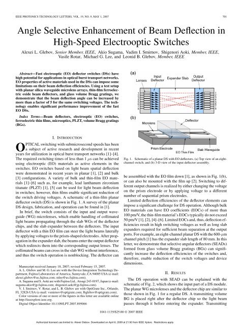
Fig. 1. Schematic of a planar DS with EO deflectors. (a) Top view of an eightchannel<br />
switch; and (b) 3-D view of the input deflector assembly.<br />
Authorized licensed use limited to: Alexei Glebov. Downloaded on April 6, 2009 at 21:50 from IEEE Xplore. Restrictions apply.<br />
be assembled with the EO film down [1], as shown in Fig. 1(b),<br />
or can also be mounted with the film up [2]. Switching to different<br />
output channels is realized by either changing the <strong>vol</strong>tage<br />
on the prism electrode or by applying <strong>vol</strong>tage to a different<br />
number of sequential prism electrodes.<br />
Limited deflection efficiencies of the deflector elements can<br />
impose a significant challenge for DS operation. Although bulk<br />
EO materials can have EO coefficients (EOCs) of more than<br />
100 pm/V, the thin-film material’s EOCs typically do <strong>no</strong>t exceed<br />
50 pm/V [1], [2], [4]–[6]. Limited EOCs and, thus, deflection efficiencies<br />
result in high switching <strong>vol</strong>tages as well as long slab<br />
expanders required for sufficient beam separation at the output<br />
ports. For example, an eight-channel planar DS with the 600- m<br />
channel pitch [1] has the expander slab length of 80 mm. In this<br />
letter, we demonstrate that selective angular deflectors (SEADs)<br />
formed from glass <strong>vol</strong>ume Bragg gratings (BGs) can significantly<br />
increase the deflection efficiencies of the switches and,<br />
therefore, enable reduction of the switch <strong>vol</strong>tages and device<br />
dimensions.<br />
II. RESULTS<br />
The DS operation with SEAD can be explained with the<br />
schematic of Fig. 2, which shows the input part of a DS module.<br />
The planar WG microlenses and the deflector chip are similar to<br />
those shown in Fig. 1 for a regular DS. A transmitting <strong>vol</strong>ume<br />
BG is placed right after the deflector chip so the light beam<br />
passes through it before entering the expander. Transmitting
702 IEEE PHOTONICS TECHNOLOGY LETTERS, VOL. <strong>19</strong>, NO. 9, MAY 1, 2007<br />
Fig. 2. Operation schematic of DS with SEAD.<br />
<strong>vol</strong>ume BGs are angle selective and only redirect the light<br />
beams meeting the grating’s Bragg condition. In Fig. 2, the<br />
beam passes through the BG unaffected. Without<br />
SEAD, the beam would be deflected at a small angle when<br />
<strong>vol</strong>tage is applied. If the SEAD is designed so that the BG’s<br />
input Bragg angle is equal to , then the beam will be further<br />
deflected at the final angle which is multiples of the original<br />
angle . All other beams entering SEAD at <strong>no</strong>n-Bragg angles<br />
will pass through the grating without amplification.<br />
Input and output angles, angle amplification strength, angular<br />
and spectral sensitivities of SEAD gratings can be varied in a<br />
wide range by adjusting the grating parameters such as refractive<br />
index contrast , spatial frequency , and grating thickness<br />
[7]. For example, the BG’s angular selectivity is approximated<br />
by and, thus, changing the grating thickness<br />
or spatial frequency enables variations of the angular<br />
selectivity in a wide range from 0.01 to several degrees. Similar<br />
dependence is valid for BG spectral selectivity which can be<br />
tuned from 0.1 to 100 nm [7]. The angle amplification strength<br />
can also be varied from a few to hundreds of times. One BG<br />
can enhance the deflection by only a given fixed factor. Thus,<br />
different gratings should be stacked in the light pass to steer<br />
beams to different output ports. It was previously demonstrated<br />
that numerous <strong>vol</strong>ume BGs can be recorded in the same <strong>vol</strong>ume<br />
without affecting each other [8].<br />
For demonstration of the deflection angle amplification, the<br />
experimental setup schematically shown in Fig. 3(a) is used.<br />
The microlens array, deflector, and SEAD with a glass slab are<br />
assembled on microstages and aligned so that the WG cores are<br />
leveled. The 1550-nm light is launched through a single-mode<br />
optical fiber into the channel WGs of the microlenses. An IR<br />
camera captures the outgoing beam images at the output edge<br />
of the slab.<br />
The microlens arrays were fabricated in a silica-on-silica<br />
planar <strong>tech<strong>no</strong>logy</strong>. The microlens design, fabrication, and<br />
properties were reported in detail in [9] and [10]. The lenses<br />
are formed on silica or silicon substrates by deposition and<br />
etching of three silica layers: lower cladding, core, and upper<br />
cladding. The 5- to 8- m-thick WG core layer is doped with Ge<br />
which increases its refractive index by 0.2%–0.5%. A scanning<br />
electron microscope (SEM) image of the microlens in Fig. 3(b)<br />
shows the shape of the microlens front side, which is formed<br />
by reactive ion etching and enables lateral collimation of light<br />
beams with widths of 200–500 m [9]. The light is confined<br />
vertically in the slab WG.<br />
The deflector element shown in Fig. 3(c) is mm<br />
in size and consists of a 10- m-thick PLZT film grown on a<br />
Fig. 3. (a) Test setup for demonstration of the SEAD operation. (b) SEM image<br />
of WG microlens array used in the experiment. (c) Thin-film PLZT deflector<br />
chip with eight-channel array of prism deflectors.<br />
Nb-doped SrTiO (Nb : STO) substrate by solid-phase epitaxy<br />
[5]. The PLZT slab WG is formed from three layers: 3- m<br />
-thick lower cladding, 2- m-thick WG core, and 5- m-thick<br />
upper cladding. The propagation losses of the WG are less than<br />
1 dB/cm. The core and cladding films have different La content,<br />
which provides the WG refractive index difference. The EOC<br />
of the film is about 40 pm/V with very weak dependence on the<br />
light polarization [1], [5]. The Nb : STO substrate is conductive,<br />
and thus serves as a lower electrode. The top electrodes, seen<br />
in Fig. 3(c), are formed from a thin gold film patterned by wet<br />
etching.<br />
Glass <strong>vol</strong>ume BGs for SEADs are formed in a photo-thermorefractive<br />
(PTR) glass, which is a sodium-zinc-aluminumsilicate<br />
glass doped with silver, cerium, and fluorine. The PTR<br />
glass <strong>tech<strong>no</strong>logy</strong> is well developed 1 and details on the glass<br />
fabrication and BG formation in PTR glasses can be found in<br />
[11]. The BGs used in this work were recorded by exposure to<br />
an interference pattern of a He–Cd laser operating at 325 nm,<br />
with dosages less than 1 J/cm . The BGs have spatial frequency<br />
of 110 mm and a thickness of about 1 mm. Fig. 4 shows the<br />
angular dependence of the light intensity diffracted by the BG<br />
with a diffraction efficiency of about 97%. The SEAD optical<br />
loss is less than 1%.<br />
In the test setup of Fig. 3(a), a 20-mm-long glass slab with BG<br />
is mounted next to the deflector chip. The slab height is about<br />
0.8 mm. The vertical light divergence in the glass slab is <strong>no</strong>t important<br />
since only lateral beam deflection is measured. In the test<br />
experiments, the air gap between the microlens array, deflector,<br />
and BG is about 5–10 m. The angular alignment sensitivity of<br />
the grating is determined by the angular selectivity of the BG<br />
shown in Fig. 4.<br />
A near-field microscope with an IR camera captures the beam<br />
position at the slab output. To evaluate quantitatively the an-<br />
1 For more detail, refer to http://www.optigrate.com.<br />
Authorized licensed use limited to: Alexei Glebov. Downloaded on April 6, 2009 at 21:50 from IEEE Xplore. Restrictions apply.
GLEBOV et al.: ANGLE SELECTIVE ENHANCEMENT OF BEAM DEFLECTION IN HIGH-SPEED EO SWITCHES 703<br />
Fig. 4. Measured angular dependence of transmitting BG at 1550 nm used for<br />
enhancement of beam deflection angle.<br />
Fig. 5. Output beam positions captured with an IR camera at the edge of the<br />
glass slab. Beam deflection with 40 V applied to the prism electrodes, (a) without<br />
and (b) with SEAD in the light pass. 1 is about 1.1 .<br />
gular enhancement, the beam deflection is measured in SEAD<br />
and <strong>no</strong>-SEAD configurations. The <strong>no</strong>-SEAD configuration is<br />
achieved by a slight angular misalignment of the glass slab with<br />
BG relative to the beam, so the Bragg condition is <strong>no</strong>t met. In<br />
this case, the transmission media and the length of the sample<br />
are identical. The same <strong>vol</strong>tage of 40 V is applied to the prism<br />
electrodes for switching in the <strong>no</strong>-SEAD and SEAD configurations<br />
and the results of the beam deflection measurements in<br />
both cases are shown in Fig. 5(a) and (b), correspondingly.<br />
The beam deflection without SEAD is shown in Fig. 5(a). The<br />
beam positions with the driving <strong>vol</strong>tage ON and OFF are presented<br />
in the top and bottom panels of the figure, respectively.<br />
With the <strong>vol</strong>tage V, the beam deflection at the output<br />
is approximately . Fig. 5(b) shows the beam deflection<br />
with SEAD for the same driving <strong>vol</strong>tage of 40 V. The beam<br />
deflection is measured to be approximately 6 , which is about<br />
5.5 times larger than in the <strong>no</strong>-SEAD configuration. It is <strong>no</strong>t<br />
seen in the figure but when the <strong>vol</strong>tage increases to 50 V, the deflected<br />
beam returns back (moves to the left) to a position just<br />
Authorized licensed use limited to: Alexei Glebov. Downloaded on April 6, 2009 at 21:50 from IEEE Xplore. Restrictions apply.<br />
slightly larger than the original . The results clearly demonstrate<br />
that SEADs can selectively amplify deflection angles in<br />
DS. The switching speeds of the devices were measured to be<br />
less than 300 ns [2]. The speed is mostly limited by the capacitance<br />
of the electrodes and can be reduced by decreasing the<br />
electrode size. The electrode size reduction can be facilitated<br />
by SEADs due to much larger deflection efficiencies, which will<br />
lead to faster switching. Integration of SEADs in DSs can provide<br />
a strong boost to the switch performance and at the same<br />
time can reduce the device cost.<br />
III. CONCLUSION<br />
We have demonstrated that glass <strong>vol</strong>ume BGs can be used<br />
to enhance deflection angles with high angular selectivity. The<br />
evaluation experiments were conducted in a test configuration<br />
using planar WG microlenses, thin-film PLZT EO deflectors,<br />
and BGs with slab expanders. The beam deflection angle increase<br />
by more than a factor of 5 was demonstrated for the same<br />
switch driving <strong>vol</strong>tage.<br />
Integration of SEADs in DS can improve the switch performance<br />
in terms of lower driving <strong>vol</strong>tages, i.e., faster or simpler<br />
driving circuitry; smaller device dimensions, i.e., more devices<br />
per wafer; faster switching; etc. Currently, glass <strong>vol</strong>ume BGs<br />
are <strong>no</strong>t available in Si-based planar tech<strong>no</strong>logies and, therefore,<br />
they can be used only for bulk-type DSs [3], or for hybrid integration<br />
of planar DS [1], [2]. Development of planar tech<strong>no</strong>logies<br />
for PTR glasses will make full integration of SEADs feasible.<br />
REFERENCES<br />
[1] A. L. Glebov, M. G. Lee, L. Huang, S. Aoki, K. Yokouchi, M. Ishii, and<br />
M. Kato, “Electrooptic planar deflector switches with thin-film PLZT<br />
active elements,” IEEE J. Sel. Topics Quantum Electron., <strong>vol</strong>. 11, <strong>no</strong>.<br />
2, pp. 422–430, Mar./Apr. 2005.<br />
[2] Y. Kai, Y. Takita, Y. Aoki, A. Sugama, S. Aoki, and H. Onaka, “4<br />
2 4 high-speed switching subsystem with VOA ( `10 um/s) using<br />
PLZT beam-deflector for optical burst switching,” in Proc. OFC Conf.,<br />
Anaheim, CA, Mar. 5–10, 2006.<br />
[3] Y. Zuo, B. Bahamin, E. J. Tremblay, C. Pulikkaseril, E. Shoukry, M.<br />
Mony, P. Langlois, V. Aimez, and D. V. Plant, “1 2 2 and 1 2 4<br />
electrooptic switches,” IEEE Photon. Tech<strong>no</strong>l. Lett., <strong>vol</strong>. 17, <strong>no</strong>. 10,<br />
pp. 2080–2082, Oct. 2005.<br />
[4] K. Nashimoto, N. Tanaka, M. LaBuda, D. Ritums, J. Dawley, M. Raj,<br />
D. Kudzuma, and T. Vo, “High-speed PLZT optical switches for burst<br />
and packet switching,” in 2nd Int. Conf. Broadband Networks, 2005,<br />
<strong>vol</strong>. 2, pp. 1118–1123.<br />
[5] K. Sato, M. Ishii, K. Kurihara, and M. Kondo, “Crystal orientation dependence<br />
of the electrooptic effect in epitaxial la-modified lead zirconate<br />
titanate films,” Appl. Phys. Lett., <strong>vol</strong>. 87, p. 25<strong>19</strong>27, 2005.<br />
[6] P. Tang, D. J. Towner, A. L. Meier, and B. W. Wessels, “Low-loss<br />
electrooptic BaTiO thin film waveguide modulator,” IEEE Photon.<br />
Tech<strong>no</strong>l. Lett., <strong>vol</strong>. 16, <strong>no</strong>. 8, pp. 1837–1839, Aug. 2004.<br />
[7] I. V. Ciapurin, V. I. Smir<strong>no</strong>v, and L. B. Glebov, “Modeling of phase<br />
<strong>vol</strong>ume diffractive gratings, part 1: Transmitting sinusoidal uniform<br />
gratings,” Opt. Eng., <strong>vol</strong>. 45, p. 015802, 2006.<br />
[8] Aug. 2006, OptiGrate Inc., private communication.<br />
[9] A. L. Glebov, L. Huang, S. Aoki, M. Lee, and K. Yokouchi, “Two-dimensional<br />
microlens arrays in silica-on-silicon planar lightwave circuit<br />
<strong>tech<strong>no</strong>logy</strong>,” J. Microlith. Microfab. Microsyst., <strong>vol</strong>. 2, pp. 309–318,<br />
2003.<br />
[10] ——, “Planar hybrid polymer-silica microlenses with tunable<br />
beamwidth and focal length,” IEEE Photon. Tech<strong>no</strong>l. Lett., <strong>vol</strong>. 16,<br />
<strong>no</strong>. 4, pp. 1107–1109, Apr. 2004.<br />
[11] L. B. Glebov, “Volume hologram recording in i<strong>no</strong>rganic glasses,” Glass<br />
Science and Tech<strong>no</strong>logy, <strong>vol</strong>. 75, pp. 73–90, 2002.