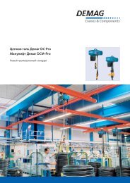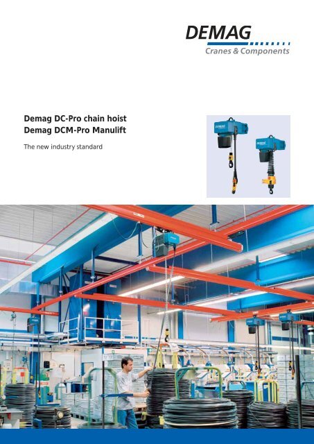
Demag DC-Pro chain hoist Demag DCM-Pro Manulift - Poduri rulante
Demag DC-Pro chain hoist Demag DCM-Pro Manulift - Poduri rulante
Demag DC-Pro chain hoist Demag DCM-Pro Manulift - Poduri rulante

You also want an ePaper? Increase the reach of your titles
YUMPU automatically turns print PDFs into web optimized ePapers that Google loves.
<strong>Demag</strong> <strong>DC</strong>-<strong>Pro</strong> <strong>chain</strong> <strong>hoist</strong><br />
<strong>Demag</strong> <strong>DC</strong>M-<strong>Pro</strong> <strong>Manulift</strong><br />
The new industry standard
2<br />
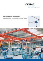
<strong>Demag</strong> <strong>hoist</strong> units:<br />
Perfect load handling<br />
High productivity, efficiency and operating reliability are<br />
the most important requirements to be met by<br />
state-of-the-art material flow systems. <strong>Demag</strong> Cranes &<br />
Contents Page<br />
<strong>DC</strong>-<strong>Pro</strong> <strong>chain</strong> <strong>hoist</strong><br />
A new industry standard 3<br />
Tailored solutions 4 – 5<br />
Increased performance, more speed 6<br />
Improved safety and reliability 7<br />
Control pendant 8 – 9<br />
Commissioning and maintenance 10 – 11<br />
<strong>DC</strong>M-<strong>Pro</strong> <strong>Manulift</strong><br />
<strong>DC</strong>M-<strong>Pro</strong> <strong>Manulift</strong> 12 – 15<br />
Accessories<br />
Pillar and wall-mounted slewing jibs 16 – 17<br />
KBK track and crane installations 18 – 19<br />
Trolleys and electric drives 20 – 23<br />
Clamp-fitted buffers and magnets 24 – 25<br />
Service 26 – 27<br />
Technical data and selection tools<br />
Selection criteria 28 – 29<br />
Technical data,<br />
selection and dimension tables 30 – 37<br />
Hoist Designer/e-tools 38<br />
Fax service 39<br />
Components develops and produces materials flow<br />
solutions for all i ndustries and companies of all sizes,<br />
from small workshops to major industrial corporations.
<strong>Demag</strong> <strong>DC</strong>-<strong>Pro</strong> <strong>chain</strong> <strong>hoist</strong>:<br />
A new industrial standard – Made by <strong>Demag</strong><br />
All inclusive: fully featured instead of extras price<br />
list<br />
Many features are already integrated into the <strong>Demag</strong><br />
<strong>DC</strong>-<strong>Pro</strong> <strong>chain</strong> <strong>hoist</strong> as standard that have to be ordered<br />
39094-4<br />
and bought as extras elsewhere.<br />
The <strong>DC</strong>-<strong>Pro</strong> <strong>chain</strong> <strong>hoist</strong> is a fully featured, highly versatile<br />
<strong>chain</strong> <strong>hoist</strong>, which can be installed and put into service in<br />
a minimum of time.<br />
That is “Standard – Made by <strong>Demag</strong>”, an investment<br />
with added value.<br />
■ 20 % longer service life and greater effi ciency thanks<br />
to <strong>Demag</strong><br />
■ Improved safety and reliability thanks to 24 V contactor<br />
control and operating limit switches<br />
■ Fast and ergonomic height-adjustment of the control<br />
cable without the need for any wiring<br />
■ Flexibility as standard thanks to two sizes of suspension<br />
bracket<br />
■ Simple installation and commissioning thanks to plug<br />
connections – Plug & Lift und Plug & Drive<br />
■ Gearbox, brake and slipping clutch are maintenancefree<br />
for up to 10 years<br />
■ Smooth and fast load handling of loads with two <strong>hoist</strong><br />
speeds<br />
■ Elapsed operating time counter and diagnostics<br />
interface provide information on the operating status –<br />
maintenance breaks can be planned<br />
■ The plug-fi tted <strong>chain</strong> drive can be replaced quickly and<br />
easily<br />
3
4<br />
Tailored solutions<br />
Certifi ed<br />
<strong>DC</strong>-<strong>Pro</strong> <strong>chain</strong> <strong>hoist</strong>s are tested and<br />
approved by the relevant authorities<br />
and also meet the demanding<br />
requirements of the CSA specifi cations.<br />
Electromagnetic compatibility<br />
is rated according to EN 61000-6-2<br />
to 4 for interference immunity<br />
in industrial environments and for<br />
interference emissions in commercial<br />
and industrial environments.<br />
1<br />
Gearbox – maintenance-free for up<br />
to 10 years. With classifi cation in FEM<br />
Group of Mechanisms <strong>Demag</strong> 2m+,<br />
the <strong>DC</strong>-<strong>Pro</strong> sets a new standard with<br />
a rated service life of 1900 hours at<br />
full load. In practical terms, this means<br />
the service life is extended by approx.<br />
20 %. The helical gearing of all<br />
gearbox stages also reduces operating<br />
noise and provides for smooth<br />
operation.<br />
5<br />
2<br />
2<br />
Brake – maintenance-free for up<br />
to 10 years (sizes <strong>DC</strong> 10 – 25 up to<br />
5 years). Thanks to minimum wear,<br />
adjustment is not necessary; short<br />
and gentle run-on path. The brake<br />
enclosure features double encapsulation<br />
and is therefore impervious<br />
to poor weather and operating<br />
conditions.<br />
3<br />
Slipping clutch – maintenance-free for<br />
up to 10 years. Integrated behind the<br />
brake in the power drive, it provides<br />
reliable protection against extreme<br />
overload. Damaging permanent<br />
slipping is not possible thanks to<br />
integrated speed monitoring.<br />
1<br />
4<br />
3<br />
7<br />
10<br />
6<br />
12<br />
11<br />
8<br />
9<br />
4<br />
Height adjustment of the control<br />
pendant – The length of the control<br />
cable and, therefore, the suspension<br />
height of the control pendant can<br />
be infi nitely varied for a hook path<br />
range of 2 – 5 m and 5 – 8 m. The<br />
length of control cable that is not<br />
required is accommodated under the<br />
service cover. The control cable is<br />
rated for electric travel applications<br />
in 3 axes.
5<br />
Control – with 24 V contactor<br />
control, operating limit switches<br />
(upper/lower) and elapsed operating<br />
time counter as standard. A geared<br />
limit switch with four contacts for<br />
fast-to-slow and limit cut-off is used<br />
as the operating limit switch for<br />
sizes <strong>DC</strong> 16 and 25.<br />
6<br />
Round steel <strong>chain</strong> – a special<br />
<strong>Demag</strong> <strong>chain</strong> of high-strength,<br />
ageing-resistant material with high<br />
surface hardness. Galvanised and<br />
additionally surface-treated to protect<br />
against hostile environments.<br />
7<br />
Suspension bracket – <strong>DC</strong>-<strong>Pro</strong> <strong>chain</strong><br />
<strong>hoist</strong>s are suspended in pendulum<br />
fashion and make optimum use of<br />
the available height thanks to their<br />
small C headroom dimension.<br />
<strong>DC</strong>-<strong>Pro</strong> units are supplied with short<br />
and long suspension brackets as<br />
standard and can always be attached<br />
to the superstructure with the<br />
optimum connection.<br />
8<br />
Housing – robust and weight-saving<br />
die-cast aluminium housing of compact<br />
and modern industrial design.<br />
UV-resistant powder-coated fi nish is<br />
unsusceptible to knocks and scratches.<br />
9<br />
Hoist motor – robust and enduring<br />
high-performance motor with large<br />
safety reserves even at high ambient<br />
temperatures and in prolonged<br />
operation. 2 <strong>hoist</strong> speeds with F4<br />
ratio as standard. (Insulation class F,<br />
360 s/h and 60 % CDF)<br />
10<br />
Chain drive – The plug-in unit<br />
facilitates quick and easy replacement<br />
of the entire <strong>chain</strong> drive without<br />
having to remove the motor or gear<br />
parts. Downtimes can therefore be<br />
cut signifi cantly. The <strong>chain</strong> drive<br />
consists of highly wear-resistant<br />
materials for a long service life.<br />
11<br />
Chain collector box – attached in<br />
pendulum fashion, made of tough,<br />
fl exible and particularly impactresistant<br />
plastic; capacity for up to<br />
8 m hook path. Chain collector bag<br />
for <strong>chain</strong> lengths up to 40 m as well<br />
as special lengths up to 120 m can<br />
be supplied.<br />
12<br />
Bottom block – up to 1000 kg with<br />
single <strong>chain</strong> fall for improved<br />
ergonomic handling of the hook with<br />
fi ttings. Chain wear is simultaneously<br />
reduced, since no <strong>chain</strong> return<br />
arrangement is required.<br />
The new, compact and particularly<br />
ergonomic <strong>DC</strong> bottom block is<br />
used for 2/1 reeving arrangements.<br />
The cut-off springs required for the<br />
limit switches are integrated inside<br />
the bottom block and therefore save<br />
60 mm of the valuable C dimension.<br />
5
6<br />
Increased performance, more speed<br />
Duration of service in full load hours<br />
Full load hours<br />
200 hours<br />
400 hours<br />
800 hours<br />
39730<br />
1600 hours<br />
1Cm 1Bm 1Am 2m FEM<br />
Increased performance, improved ergonomics, safety<br />
and reliability for greater productivity. The performance<br />
features of the new <strong>DC</strong>-<strong>Pro</strong> <strong>chain</strong> <strong>hoist</strong> provide for<br />
optimum effi ciency.<br />
Sensitive and fast<br />
<strong>DC</strong>-<strong>Pro</strong> units can be integrated into your work and<br />
production processes fl exibly and precisely. While the<br />
main lifting speed guarantees fast and effective operation<br />
at a minimum of 6 m/min, the creep lifting speed ensures<br />
that loads are handled gently and precisely.<br />
– an even longer service life for greater<br />
effi ciency.<br />
In practical terms, <strong>Demag</strong> means the service life is<br />
extended by approx. 20 % in comparison with the<br />
conventional 2m classifi cation for <strong>chain</strong> <strong>hoist</strong>s according<br />
to the FEM Group of Mechanisms. This results in signifi -<br />
cantly extended intervals for service work and general<br />
overhauls. This extra amount of lasting effi ciency is only<br />
offered by the new <strong>Demag</strong> <strong>DC</strong>-<strong>Pro</strong> <strong>chain</strong> <strong>hoist</strong>.<br />
1900 hours
Improved safety and reliability<br />
Motor<br />
Driving<br />
Braking<br />
Chain drive<br />
Slipping clutch<br />
Gearbox<br />
Brake<br />
Speed<br />
detection<br />
Thanks to the completely new safety concept developed<br />
for the <strong>Demag</strong> <strong>DC</strong>-<strong>Pro</strong> <strong>chain</strong> <strong>hoist</strong>, the gearbox, brake<br />
and coupling operate without the need for any maintenance<br />
for up to ten years (brake for sizes <strong>DC</strong> 10 – 25<br />
up to 5 years). The brake-coupling system ensures that<br />
the load is held securely in any operating situation. The<br />
load cannot drop. This is achieved by arrangement of the<br />
brake direct in the power drive <strong>chain</strong> (red line). Thanks to<br />
minimum wear, the brake does not need to be adjusted.<br />
Operating safety is generally improved by the single-fall<br />
design up to a load capacity of 1000 kg.<br />
39600-3<br />
The combination of electronic control system and<br />
integrated speed sensors continuously monitor the <strong>hoist</strong><br />
motor, clutch and brake, thus ensuring lasting safety for<br />
the operator. The compact and light 24 V contactor control<br />
system also ensures that the system is subject to only minimum<br />
wear. The run-on path is both smooth and gentle.<br />
The standard control system includes<br />
■ 24 V contactor control<br />
■ Operating limit switches (upper/lower) to switch the<br />
<strong>hoist</strong> motion off in the highest and lowest hook<br />
positions – sizes <strong>DC</strong> 16 and 25 with geared limit switch<br />
with four contacts for for fast-to-slow and limit cut-off<br />
■ Elapsed operating time counter can be read<br />
from the outside<br />
■ Speed detection<br />
■ Infrared diagnostics interface<br />
7
8<br />
Control pendant:<br />
Always at the right operating height<br />
39415-2 39745-6<br />
The most favourable operating height for the control<br />
pendant can be easily adjusted on the <strong>Demag</strong> <strong>DC</strong>-<strong>Pro</strong> <strong>chain</strong><br />
<strong>hoist</strong>. The adjusting mechanism integrated in the <strong>chain</strong><br />
<strong>hoist</strong> housing enables the operator to change the<br />
suspension height of the control pendant easily and<br />
without the need for any tools or wiring. The control<br />
cable is designed for an adjustment range of 3 m.<br />
The length of control cable that is not required<br />
disappears beneath the <strong>DC</strong>-<strong>Pro</strong> service cover. This<br />
innovation has been implemented for the fi rst time<br />
in a <strong>chain</strong> <strong>hoist</strong>.<br />
39045<br />
Height adjustment of the control cable<br />
The adjusting mechanism also contains the strain relief<br />
arrangement for the control cable and can resist extreme<br />
tensile loads. The same applies to the control cable,<br />
which is made of a proven and particularly tough material.<br />
At the same time, the control cable is fl exible and therefore<br />
easy to handle.
Ergonomics:<br />
All in good hand<br />
The DSC control pendant precisely interprets control<br />
commands in any situation. It facilitates fatigue-free<br />
operation for right and left-handed operators both with<br />
and without gloves. Furthermore, electrical interlocks<br />
prevent simultaneous initiation of motions in both directions.<br />
<strong>Demag</strong> control pendants feature an optimised ergonomic<br />
sloping design for convenient operation. They are made<br />
of high-quality plastic which is highly resistant to impacts<br />
and are therefore extremely robust. With bending and<br />
impact protection as well as IP 65 enclosure against<br />
dust and moisture, DSC units are ideally suited for the<br />
demanding requirements of industrial applications.<br />
The DSC control pendant is specially developed for<br />
push-travel <strong>DC</strong>-<strong>Pro</strong> <strong>chain</strong> <strong>hoist</strong>s and fi tted with two-stage<br />
switching elements. The DSE 10-C control pendant is<br />
used for electric travel applications with E 11 / E 22 or<br />
E 34 drives.<br />
The control pendant can be changed quickly and easily<br />
39031-1<br />
Slide the protective sleeve upwards<br />
over the control cable<br />
Fit the plug with its bayonet<br />
connector into the control pendant<br />
and turn until it locks<br />
39546-1<br />
39031-3 39031-5<br />
Push protective sleeve downwards<br />
9
10<br />
Commissioning:<br />
Plug & Lift and Plug & Drive<br />
A great benefi t offered by the new <strong>Demag</strong> <strong>DC</strong>-<strong>Pro</strong> <strong>chain</strong><br />
<strong>hoist</strong> is simple commissioning. The pivoting suspension<br />
bracket and infi nitely adjustable fl ange width of the<br />
U 11, U 22 and U 34 trolleys make the mechanical parts<br />
easy to install.<br />
Pivoting service cover<br />
The plug-in connections beneath the service cover and<br />
the power plugs that are already included in the scope of<br />
delivery also make the electrical parts simple to connect.<br />
This enables the <strong>DC</strong>-<strong>Pro</strong> to be ready for operation in a<br />
minimum of time.<br />
39044-2<br />
Integrated beneath the cover<br />
You have rapid access to all important<br />
components for service and<br />
commissioning beneath the pivoting<br />
service cover<br />
■ Storage for 3 m of control cable<br />
■ Plug-in electrical connections for<br />
power cable, control cable, limit<br />
switches and trolley<br />
■ Strain relief for power supply and<br />
trolley supply cables<br />
■ Chain guide<br />
■ Chain lubrication
Maintenance:<br />
Fast and simple<br />
All main drive components of the <strong>Demag</strong> <strong>DC</strong>-<strong>Pro</strong> <strong>chain</strong><br />
<strong>hoist</strong>, such as the gearbox, brake and coupling, operate<br />
without the need for any maintenance for up to ten years<br />
(maintenance-free brake for up to 5 years for sizes 10 – 25).<br />
The outstanding <strong>Demag</strong> quality of all components provides<br />
for a long service life even under heavy use. The<br />
few necessary maintenance measures can be carried out<br />
quickly and easily thanks to the service-friendly design of<br />
the <strong>DC</strong>-<strong>Pro</strong>.<br />
The <strong>chain</strong> drive of the <strong>DC</strong>-<strong>Pro</strong>, for example, is designed<br />
as a compact unit which is plugged into place and can<br />
be replaced in a minimum of time without the need to<br />
disassemble motor or gearbox parts. Long downtimes<br />
as a result of maintenance work are now a thing of the<br />
past.<br />
39241-22<br />
Diagnosis – wireless via display<br />
or via infrared<br />
Service technicians can read the<br />
standard operating time counter or<br />
call up the relevant information on<br />
the operating status – from the<br />
outside via the display on the base of<br />
the <strong>chain</strong> <strong>hoist</strong> housing or by means<br />
of the diagnosis interface via infrared<br />
data transfer.<br />
Chain drive Diagnosis interface<br />
39241-26<br />
11
12<br />
<strong>Demag</strong> <strong>DC</strong>M-<strong>Pro</strong> <strong>Manulift</strong>:<br />
Ergonomic single-handed load handling at the workplace<br />
The <strong>DC</strong>M-<strong>Pro</strong> <strong>Manulift</strong> was developed for handling loads<br />
quickly and safely with only one hand. The new <strong>DC</strong>M-<strong>Pro</strong><br />
is based on the lifting unit of the <strong>DC</strong>-<strong>Pro</strong> <strong>chain</strong> <strong>hoist</strong> and<br />
the DSM-C control unit which is connected to it by a<br />
helical cable. Thanks to the control unit which is rigidly<br />
connected to the load handling attachment for right and<br />
left-handed operation, the operator only needs one hand<br />
to operate the <strong>chain</strong> <strong>hoist</strong> and guide the load.<br />
39143<br />
The quick-change coupling enables a wide variety of<br />
load handling attachments to be changed with ease.<br />
All <strong>Manulift</strong> load handling attachments are fi tted with<br />
a connecting pin with a swivel lock, which snaps into<br />
the quick-change coupling. It can be easily disconnected<br />
by lifting the unlocking sleeve.<br />
<strong>Manulift</strong> units can travel on <strong>Demag</strong> KBK profi le sections<br />
and I-beams (see pages 16 – 23), which enables them to<br />
be fl exibly integrated into work and production processes.<br />
Load hook<br />
250 kg<br />
Slewing load hook<br />
250 kg<br />
Open hook<br />
125 kg<br />
39204-7<br />
Belt sling<br />
125 kg
Versatile adaptability to any task<br />
A variety of proven load handling attachments facilitate<br />
optimum and fl exible adaptation of the <strong>chain</strong> <strong>hoist</strong> to<br />
meet your needs. They range from normal load hooks<br />
and various pantograph-type tongs to parallel gripper<br />
systems, e.g. for KLT containers used in the automotive<br />
industry. The <strong>DC</strong>M-<strong>Pro</strong> <strong>Manulift</strong> can be used with<br />
specially developed load handling attachments.<br />
The universal coupling pin is used to connect customerdesigned<br />
attachments.<br />
PGS-parallel gripper<br />
125 kg<br />
38922<br />
Pantograph tongs for<br />
gripping square goods<br />
125 kg<br />
Unlocking sleeve<br />
Load retainer<br />
Coupling pin<br />
It is provided with an M12 internal thread for connecting<br />
special load handling attachments.<br />
<strong>Manulift</strong> load handling attachments can also be connected<br />
to the <strong>DC</strong>-<strong>Pro</strong> <strong>chain</strong> <strong>hoist</strong> load hook by means of<br />
an adapter. The versatility and fl exibility of the new<br />
<strong>Demag</strong> <strong>chain</strong> <strong>hoist</strong> provide for improved load handling<br />
effi ciency at the workplace.<br />
The quick-change coupling on the DSM-C control unit<br />
Pantograph tongs for<br />
gripping round goods<br />
125 kg<br />
Load hook adapter<br />
up to 250 kg<br />
Pressure spring<br />
Cylindrical pin<br />
Swivel lock<br />
410898I.eps<br />
Load hook adapter<br />
with connected<br />
PGS shaft gripper<br />
13
14<br />
PGS parallel gripper system:<br />
Firm hold on loads up to 125 kg<br />
PGS box grippers<br />
The narrow design and short opening path of the grippers<br />
make it possible to pick up and deposit goods safely and<br />
easily, even in restricted spaces, and to place them direct<br />
into cartons. The 100 mm wide gripping range makes it<br />
possible to transport both the actual goods as well as a<br />
packed unit using the same gripper.<br />
37452-10<br />
419704.eps 419703.eps<br />
PGS shaft grippers<br />
Various shaft grippers are available which can be adapted<br />
to different shaft types and applications by changing the<br />
gripper jaws.<br />
When fi tted with a shaft support, they can be used to<br />
pick up shafts with various diameters or an unknown<br />
centre of gravity. This signifi cantly improves the safety of<br />
handling tasks that, until now, have always involved a<br />
certain risk.<br />
39229-1
PGS container grippers<br />
The various container grippers can be supplied for fi xed<br />
or adjustable container widths. They are easily adjusted<br />
to the relevant container size by lifting and turning the<br />
locking pins, and by pushing the grippers together or<br />
pulling them apart until the stops are reached.<br />
Container type<br />
423015.eps<br />
37892-8 423013.eps 423012.eps<br />
Grippers for various container types<br />
Container size<br />
600 x 400 400 x 300<br />
Euro container rigid rigid<br />
KLT ( VDMA )<br />
Various containers such as<br />
PDB, ARCA, MF,<br />
SSI Schäfer, Eurotec, Utz<br />
KLT, Bito<br />
Grippers for other container types on request<br />
rigid rigid<br />
adjustable<br />
rigid rigid<br />
adjustable<br />
15
16<br />
Slewing jibs facilitate load handling at the workplace<br />
Pillar- and wall-mounted slewing jibs with the <strong>DC</strong>-<strong>Pro</strong><br />
<strong>chain</strong> <strong>hoist</strong> provide inexpensive support at the workplace<br />
and facilitate space-saving load handling in production,<br />
storage and shipping. When used direct on production<br />
Wall-mounted slewing jibs<br />
These cranes, which take up no fl oor space, can be used<br />
wherever load-bearing concrete walls or pillars are<br />
available. The slewing range of up to 270° and the possibility<br />
to fi t them to machinery and installations makes<br />
them ideal for a wide range of applications.<br />
machinery, they help to cut setting-up and idle times.<br />
Wall- and pillar-mounted slewing jibs and pillar-mounted<br />
slewing cranes are suitable for virtually any application<br />
as standard.<br />
39026-2 39095-1<br />
Pillar-mounted slewing jibs and cranes<br />
The locations served by these free-standing cranes are<br />
utilised to the full thanks to their slewing range of up<br />
to n x 360°. They can be used for many applications.<br />
They can be erected indoors or outside and used for<br />
handling goods at loading ramps or for serving<br />
machinery. These cranes provide maximum hook paths<br />
even where only little headroom is available. The pillar<br />
has only a small footprint and is either anchored to the<br />
foundations using anchor rods or to an existing concrete<br />
fl oor using anchor bolts.
KBK slewing jibs feature struts and hollow profi le section<br />
rails and offer a low deadweight for load capacities up<br />
to 1000 kg. Loads can be moved quite simply by hand.<br />
The product range of the I-beam slewing jibs covers<br />
a load range up to 10000 kg as standard.<br />
See brochure 208 756 44 for further information<br />
on pillar and wall-mounted slewing jibs and cranes.<br />
39187-1<br />
17
18<br />
Effi cient material fl ow with KBK track and crane installations<br />
Interlinking production processes, serving machinery,<br />
moving materials – all handling and transport tasks have<br />
one thing in common: loads not only have to be lifted<br />
and lowered, horizontal motions are also required.<br />
39741-10<br />
Suspension cranes<br />
Single and double-girder suspension cranes are used for<br />
area-serving load handling. The low deadweight enables<br />
loads to be easily moved by hand. Travel drives are also<br />
available for precise positioning of larger loads.<br />
The KBK crane construction kit is the ideal horizontal<br />
transport system for the <strong>DC</strong>-<strong>Pro</strong> and <strong>DC</strong>M-<strong>Pro</strong> <strong>Manulift</strong>.<br />
KBK installations are used for both linear and areaserving<br />
load transport.<br />
KBK sections are available in various sizes for different load capacities<br />
39042-4<br />
Portal cranes<br />
Portal cranes from the KBK system are not mounted on<br />
rails and can be easily moved. When fi tted with the<br />
<strong>DC</strong>-<strong>Pro</strong> <strong>chain</strong> <strong>hoist</strong>, this makes them ideal and fl exible<br />
lifting devices, above all for repair and assembly work.<br />
29463
Many components are available to create effi cient<br />
overhead materials handling solutions to meet specifi c<br />
application requirements.<br />
The KBK crane construction kit is a suspension system<br />
which uses no valuable fl oor space and therefore leaves<br />
Sections in various profi le sizes<br />
for curved tracks<br />
34497<br />
37979-3<br />
KBK Aluline – aluminium profi le<br />
sections<br />
production area free. It is completely modular in design,<br />
all connections are bolted or fi tted. This enables<br />
installations to be modifi ed or extended easily and<br />
cost-effectively. These are <strong>Demag</strong> system solutions for<br />
practical material fl ow requirements.<br />
36147<br />
Suspension monorails<br />
Suspension monorails are the<br />
preferred linear solution to connect<br />
pick-up and deposit positions. The<br />
many possible designs from simple,<br />
manually controlled straight sections<br />
to complex, semi or fully automated<br />
closed-circuit monorail systems<br />
enable a wide variety of applications<br />
to be implemented. Flexible routing<br />
by means of straight and curved<br />
sections, track switches and<br />
turntables facilitates cost-effective<br />
adaptation to the most diverse<br />
operating conditions.<br />
See brochure 208 385 44 for<br />
further information on track and<br />
crane systems from the KBK crane<br />
construction kit.<br />
19
20<br />
Push-travel trolleys for simple horizontal movement<br />
U trolley<br />
The new U trolley generation is available in two sizes for<br />
load capacities up to 1100 kg (U 11), 2200 kg (U 22)<br />
and 3400 kg (U 34). The fl ange width can be infi nitely<br />
adjusted by means of two adjusting rings and covers the<br />
ranges from 58 mm to 200 mm, and 201 mm to 310 mm.<br />
This facilitates fast and simple installation.<br />
The travel rollers, which are made of high-strength and<br />
wear-resistant Polyamide, provide for smooth operating<br />
characteristics and low travel resistance. Optional steel<br />
rollers can also be used for special ambient conditions,<br />
e.g. high temperatures. The universal design of the travel<br />
rollers enables them to be used for operation on straight<br />
and sloping profi le sections.<br />
39032-1
39087-2<br />
39136-1<br />
The lateral steel guide rollers support their curvenegotiating<br />
properties down to the minimum radius of<br />
1000 mm and minimise girder wear. A drop-stop<br />
arrangement is integrated into the side cheeks, which<br />
consist of aluminium die-castings with a powder-coated<br />
fi nish.<br />
Push-travel U trolleys are designed for simple addition of<br />
the E electric travel drive at a later date.<br />
CF 5 click-fi t trolley<br />
Simply clicked onto the girder, curve-negotiating Click-fi t<br />
trolleys are ready for operation with a load capacity of up<br />
to 550 kg.<br />
The fl ange widths from 58 to 91 mm, the minimum<br />
curve radius of 800 mm and easy adaptability to standard<br />
section or parallel fl ange girders make them suitable<br />
for universal applications. The integrated drop-stop and<br />
lift-off protection provides for safe operation.<br />
21
22<br />
Plug & Drive with electric trolleys<br />
EU trolley<br />
The E 11, E 22 and E 34 electric travel drives were specially<br />
developed for operation with the new <strong>DC</strong>-<strong>Pro</strong> <strong>chain</strong> <strong>hoist</strong>.<br />
This signifi cantly extends the range of applications of this<br />
state-of-the-art <strong>hoist</strong>.<br />
The travel drives can be adapted to the U 11 – U 34<br />
trolleys. Particularly short approach dimensions can be<br />
achieved when the units are mounted in a vertical<br />
arrangement. Fast retro-fi tting and commissioning offer<br />
further benefi ts as no changes need to be made to<br />
the push-travel trolleys.<br />
39164-3
The drive is simply connected to the <strong>DC</strong>-<strong>Pro</strong> <strong>chain</strong> <strong>hoist</strong><br />
using plug connectors and operated by means of the<br />
newly developed DSE 10-C control pendant. The control<br />
pendant for long and cross travel is simply fi tted by<br />
means of a connector. The E 22 travel drive is used as<br />
standard for the KBK rail system with the new RF 125<br />
friction wheel travel drive.<br />
The E electric travel drive features a state-of-the-art,<br />
compact industrial design and offers outstanding travel<br />
characteristics. The control system integrated in the<br />
travel unit provides for gentle starting and braking for<br />
low-sway load handling. A convenient load-sway<br />
damping system can be activated for the cross-travel<br />
motion. The speeds and acceleration and braking rates<br />
can also be modifi ed by means of the DSE-10 C control<br />
pendant, if required. All electrical connections are of<br />
plug-in design.<br />
The trolleys can also be fi tted with an optional cross-type<br />
limit witch, either with fast-to-slow and limit switch<br />
cut-off or only with limit switch cut-off.<br />
39208-1 39209<br />
23
24<br />
Clamp-fi tted buffers to limit travel<br />
KPA/KPT clamp-fi tted buffers are the ideal solution to<br />
limit travel and are suitable for all <strong>DC</strong>-<strong>Pro</strong> trolleys. They<br />
can be fi tted to sloping and parallel I-beam girders quickly<br />
and easily using screws. The travel range is shortened or<br />
extended by simply relocating the buffers.<br />
They can be adapted to fl ange widths from 50 to<br />
300 mm for universal applications.<br />
They are suitable temperature ranges from -20°C<br />
to + 70°C as well as for operation outdoors thanks<br />
to adequate resistance to ageing, ozone and weather<br />
conditions. Furthermore, they offer good resistance<br />
to acids and lyes. The tightening torque details are cast<br />
into the buffer to ease assembly.<br />
39716
Magnets as versatile load handling attachments<br />
DPMN permanent magnets<br />
They offer low operating costs, constant availability<br />
and versatility and are suitable for operation both inside<br />
manufacturing facilities and outdoors. They function<br />
independently of a power supply and are safe, easy and<br />
reliable to operate.<br />
When switched to “magnetise”, a magnetic fi eld is created<br />
between two fi eld poles; no magnetism remains when<br />
switched to “demagnetise”. The outer surface of the<br />
magnet armature is always neutral and offers maximum<br />
protection against external infl uences.<br />
DBM 34/68 battery magnets<br />
The compact unit consists of an electromagnet, battery<br />
and control unit with an integrated charging set. Battery<br />
magnets operate independently of a mains power supply<br />
and are used in stationary and travelling applications.<br />
They offer safe, reliable and easy operation in stores or<br />
production areas. The charging operation is controlled<br />
automatically and the charge level is indicated by the<br />
battery monitoring display.<br />
38476<br />
36387 19763<br />
R 26 round magnets<br />
These single magnets offer enormous strength. The solid<br />
housing is made of highly permeable steel and the coil<br />
consists of fully encapsulated enamelled copper wire.<br />
They are fi tted with integrated rectifi ers and switches as<br />
standard.<br />
25
26<br />
Service – ready to help around the clock<br />
All over the world<br />
We offer you service around the clock with our worldwide<br />
network of <strong>Demag</strong> expert service teams and<br />
<strong>Demag</strong> partners. This ensures the highest availability and<br />
safety in your installation.<br />
Rapid and reliable spare part supply<br />
Any spare parts needed can be shipped 24 hours a day,<br />
7 days a week.<br />
39464-2<br />
Service systems: <strong>Demag</strong> IDAPSY<br />
We have developed a new integrated service system<br />
for the new <strong>Demag</strong> <strong>DC</strong>-<strong>Pro</strong> <strong>chain</strong> <strong>hoist</strong>: <strong>Demag</strong> IDAPSY.<br />
IDAPSY stands for Inspection Diagnosis Application<br />
System.<br />
And these are your benefi ts:<br />
■ Transparency<br />
By recording utilisation of the installation, <strong>Demag</strong><br />
IDAPSY facilitates predictive and plannable service.<br />
This enables a high level of availability to be ensured.<br />
■ Analysis<br />
Recorded data provides an excellent basis for analysis.<br />
The load spectrum recorder can be read out or error<br />
messages can be called up for maintenance or repair<br />
purposes, for example.<br />
■ Effi ciency<br />
Maintenance work carried out in good time to ensure<br />
your installation is in optimum condition increases<br />
overall effi ciency.<br />
<strong>Demag</strong> IDAPSY enables service work to be carried out<br />
more quickly. This means that your <strong>hoist</strong> is ready for<br />
operation again even more quickly if service work has to<br />
be carried out.<br />
Your individual service package<br />
<strong>Demag</strong> Service and our <strong>Demag</strong> partners offer a<br />
comprehensive portfolio of services to ensure the lasting<br />
availability of your installation throughout its entire lifecycle:<br />
■ Recurring inspections according to relevant accident<br />
prevention regulations<br />
■ Inspection and maintenance<br />
■ Fault elimination both with and without on-call<br />
standby<br />
■ Service training for operators and maintenance<br />
engineers
39040<br />
39040<br />
27
28<br />
Selection criteria<br />
The size of the <strong>hoist</strong> is determined by the load spectrum,<br />
average operating time per working day, SWL and<br />
reeving.<br />
The load spectrum<br />
(in most cases estimated) can be evaluated in accordance with the following defi nitions:<br />
Load capacity<br />
1 Light<br />
Hoist units which are usually subject to very small loads<br />
and only in exceptional cases to maximum loads.<br />
Load capacity<br />
Small partial load<br />
Small dead load<br />
Operating time<br />
Operating time<br />
Heavy partial load<br />
Medium partial load<br />
Medium dead load<br />
2 Medium<br />
Hoist units which are usually subject to small loads<br />
but rather often to maximum loads.<br />
1. What are the operating conditions?<br />
2. What is the specifi ed safe working load?<br />
3. To what height must the load be lifted?<br />
4. What is the required lifting speed?<br />
5. Do the loads need to be lifted and lowered with high<br />
precision?<br />
6. Is horizontal load travel necessary?<br />
7. How is the <strong>hoist</strong> to be controlled?<br />
Load capacity<br />
Operating time<br />
Heavy dead load<br />
3 Heavy<br />
Hoist units which are usually subject to medium loads<br />
but frequently to maximum loads.<br />
Load capacity<br />
Operating time<br />
Very heavy<br />
dead load<br />
4 Very heavy<br />
Hoist units which are usually subject to maximum<br />
and almost maximum loads.
The group is determined by the load spectrum and operating time.<br />
Load spectrum Average operating time<br />
per day in hours<br />
L1 Light 2-4 4-8 8-16 over 16<br />
L2 Medium 1-2 2-4 4-8 8-16<br />
L3 Heavy 0.5-1 1-2 2-4 4-8<br />
L4 Very heavy 0.25-0.5 0.5-1 1-2 2-4<br />
Group of mechanisms to FEM 1Am 2m+ 3m 4m<br />
Reeving<br />
SWL in kg<br />
Range Size<br />
1/1 2/1<br />
80<br />
<strong>Demag</strong> <strong>DC</strong> <strong>chain</strong> <strong>hoist</strong><br />
<strong>DC</strong>-<strong>Pro</strong> 1 / <strong>DC</strong>-<strong>Pro</strong> 2 80<br />
100 <strong>DC</strong>-<strong>Pro</strong> 1 / <strong>DC</strong>-<strong>Pro</strong> 2 100<br />
125 <strong>DC</strong>-<strong>Pro</strong> 1 / <strong>DC</strong>-<strong>Pro</strong> 2 125<br />
160 <strong>DC</strong>-<strong>Pro</strong> 2 160<br />
160 <strong>DC</strong>-<strong>Pro</strong> 5 160<br />
200 <strong>DC</strong>-<strong>Pro</strong> 2 200<br />
200 <strong>DC</strong>-<strong>Pro</strong> 5 200<br />
250 <strong>DC</strong>-<strong>Pro</strong> 2 250<br />
252 <strong>DC</strong>-<strong>Pro</strong> 5 250<br />
315 <strong>DC</strong>-<strong>Pro</strong> 5 315<br />
315 <strong>DC</strong>-<strong>Pro</strong> 10 315<br />
400 <strong>DC</strong>-<strong>Pro</strong> 5 400<br />
400 <strong>DC</strong>-<strong>Pro</strong> 10 400<br />
500 <strong>DC</strong>-<strong>Pro</strong> 5 500<br />
500 <strong>DC</strong>-<strong>Pro</strong> 10 500<br />
630 <strong>DC</strong>-<strong>Pro</strong> 10 630<br />
800 <strong>DC</strong>-<strong>Pro</strong> 10 800<br />
1000 <strong>DC</strong>-<strong>Pro</strong> 10 1000<br />
1250 <strong>DC</strong>-<strong>Pro</strong> 10 1250<br />
1250 <strong>DC</strong>-<strong>Pro</strong> 16 1250<br />
1250 <strong>DC</strong>-<strong>Pro</strong> 10 1250<br />
1600 <strong>DC</strong>-<strong>Pro</strong> 16 1600<br />
1600 <strong>DC</strong>-<strong>Pro</strong> 10 1600<br />
2000 <strong>DC</strong>-<strong>Pro</strong> 25 2000<br />
2000 <strong>DC</strong>-<strong>Pro</strong> 10 2000<br />
2500 <strong>DC</strong>-<strong>Pro</strong> 25 2500<br />
2500 <strong>DC</strong>-<strong>Pro</strong> 10 2500<br />
3200 <strong>DC</strong>-<strong>Pro</strong> 16 3200<br />
4000 <strong>DC</strong>-<strong>Pro</strong> 25 4000<br />
5000 <strong>DC</strong>-<strong>Pro</strong> 25 5000<br />
Example:<br />
SWL 250 kg<br />
Load spectrum „medium“ from table<br />
Lifting speed 8 m/min;<br />
1/1 reeving<br />
average hook path 4 m;<br />
Number of cycles/hour 20<br />
Working time/day 8 hours<br />
The average operating time per working day is estimated or<br />
calculated as follows:<br />
2 · average hook path · no. of cycles/h · working time/day<br />
Operating time/day =<br />
60 · speed <strong>hoist</strong><br />
2 · 4 · 20 ·8<br />
=<br />
= 2.66 hours<br />
60 · 8<br />
For the medium load spectrum and an average daily operating time of<br />
2.66 hours, the table shows group 2m+. For a load capacity of 250 kg,<br />
the diagram shows size <strong>DC</strong>-<strong>Pro</strong> 2-250.<br />
29
30<br />
Technical data<br />
Model code<br />
EU <strong>DC</strong>-<strong>Pro</strong> 10 - 2000 2/1 H5 V6/1,5 380 - 415 / 50 24/6 100<br />
Flange width [mm] or I beam<br />
Travel speed [m/min]<br />
Frequency [Hz]<br />
Voltage range <strong>chain</strong> <strong>hoist</strong> [V]<br />
Hoist speed [m/min]<br />
Hook path [m]<br />
Reeving<br />
Load capacity [kg]<br />
Size<br />
<strong>DC</strong> <strong>Demag</strong> <strong>chain</strong> <strong>hoist</strong><br />
CF<br />
U<br />
R<br />
Load<br />
capacity<br />
Trolley type<br />
Click-fi t trolley<br />
Travelling <strong>hoist</strong><br />
Push travel<br />
E<br />
D<br />
1) 2m+ corresponds to 1900 hours at full load<br />
Electric travel drive<br />
Articulated trolley<br />
<strong>Demag</strong> <strong>DC</strong>M-<strong>Pro</strong> <strong>Manulift</strong> selection table<br />
<strong>Manulift</strong> Hoist speed Motor size Hook path Group of<br />
mechanisms<br />
42598647.eps<br />
Reeving Max. weight<br />
for 2,8 and 4,3<br />
hook path<br />
[kg] Typ [m/min at 50 Hz] [m/min at 60 Hz] [m] FEM [kg]<br />
80<br />
<strong>DC</strong>M-<strong>Pro</strong> 1 - ... 8/2 9.6/2.4<br />
<strong>DC</strong>M-<strong>Pro</strong> 2 - ... 16/4 19.2/4.8<br />
2.8<br />
4m<br />
<strong>DC</strong>M-<strong>Pro</strong> 1 - ... 8/2 9.6/2.4 ZNK 71 B 8/2<br />
22 / 23<br />
125<br />
and<br />
1/1<br />
<strong>DC</strong>M-<strong>Pro</strong> 2 - ... 16/4 19.2/4.8<br />
<strong>DC</strong>M-<strong>Pro</strong> 2 - ... 8/2 9.6/2.4<br />
4.3<br />
2m+<br />
250<br />
1)<br />
<strong>DC</strong>M-<strong>Pro</strong> 5 - ... 16/4 19.2/4.8 ZNK 80 B 8/2 4m 28 / 29<br />
<strong>Demag</strong> <strong>DC</strong>M-<strong>Pro</strong> <strong>Manulift</strong> dimension table<br />
Size<br />
Short suspension bracket Long suspension bracket<br />
C C1 C C1<br />
for hook path<br />
Chain<br />
collector box<br />
for hook path<br />
Chain<br />
collector box<br />
2.8 m 4.3 m H5 2.8 m 4.3 m H5<br />
<strong>DC</strong>M-<strong>Pro</strong> 1 635 705 335 673 743 373<br />
<strong>DC</strong>M-<strong>Pro</strong> 2 635 705 335 673 743 373<br />
<strong>DC</strong>M-<strong>Pro</strong> 5 680 750 395 718 788 435
<strong>DC</strong>-<strong>Pro</strong> <strong>chain</strong> <strong>hoist</strong> selection table<br />
SWL Chain <strong>hoist</strong> Hoist speed Motor size Hook path 2) Group of<br />
mechanisms<br />
1) 2m+ corresponds to 1900 hours at full load 2) Longer hook paths possible, please enquire<br />
Reeving Max. weight<br />
at H5 / H8<br />
respect. H4<br />
[kg] Typ [m/min at 50 Hz] [m/min at 60 Hz] [m] FEM [kg]<br />
80<br />
100<br />
125<br />
160<br />
200<br />
250<br />
315<br />
400<br />
500<br />
<strong>DC</strong>-<strong>Pro</strong> 1 -... 8/2 9.6/2.4<br />
<strong>DC</strong>-<strong>Pro</strong> 2 -... 16/4 19.2/4.8<br />
<strong>DC</strong>-<strong>Pro</strong> 1 -... 8/2 9.6/2.4<br />
<strong>DC</strong>-<strong>Pro</strong> 2 -... 16/4 19.2/4.8<br />
<strong>DC</strong>-<strong>Pro</strong> 1 -... 8/2 9.6/2.4<br />
<strong>DC</strong>-<strong>Pro</strong> 2 -... 16/4 19.2/4.8<br />
ZNK 71 B 8/2<br />
<strong>DC</strong>-<strong>Pro</strong> 2 -... 8/2 9.6/2.4<br />
<strong>DC</strong>-<strong>Pro</strong> 5 -... 16/4 19.2/4.8 ZNK 80 B 8/2 28 / 30<br />
<strong>DC</strong>-<strong>Pro</strong> 2 -... 8/2 9.6/2.4 ZNK 71 B 8/2 3m 22 / 24<br />
<strong>DC</strong>-<strong>Pro</strong> 5 -... 16/4 19.2/4.8 ZNK 80 B 8/2 4m 28 / 30<br />
<strong>DC</strong>-<strong>Pro</strong> 2 -... 8/2 9.6/2.4 ZNK 71 B 8/2 2m+ 1)<br />
<strong>DC</strong>-<strong>Pro</strong> 5 -... 16/4 19.2/4.8 ZNK 80 A 8/2 4m 28 / 30<br />
5 and 8<br />
1/1<br />
<strong>DC</strong>-<strong>Pro</strong> 5 -... 8/2 9.6/2.4 ZNK 80 A 8/2<br />
28 / 30<br />
4m<br />
<strong>DC</strong>-<strong>Pro</strong> 10 -... 12/3 14.4/3.6 ZNK 100 A 8/2 48 / 52<br />
<strong>DC</strong>-<strong>Pro</strong> 5 -... 8/2 9.6/2.4 ZNK 80 A 8/2 3m 28 / 30<br />
<strong>DC</strong>-<strong>Pro</strong> 10 -... 12/3 14.4/3.6 ZNK 100 A 8/2 4m 48 / 52<br />
<strong>DC</strong>-<strong>Pro</strong> 5 -... 8/2 9.6/2.4 ZNK 80 A 8/2 2m+ 1)<br />
28 / 30<br />
<strong>DC</strong>-<strong>Pro</strong> 10 -... 12/3 14.4/3.6 ZNK 100 A 8/2 4m 48 / 52<br />
630 <strong>DC</strong>-<strong>Pro</strong> 10 -...<br />
800 <strong>DC</strong>-<strong>Pro</strong> 10 -...<br />
1000 <strong>DC</strong>-<strong>Pro</strong> 10 -...<br />
1250<br />
1600<br />
2000<br />
2500<br />
4m<br />
22 / 24<br />
22 / 24<br />
6/1.5 7.2/1.8 ZNK 100 A 8/2<br />
48 / 52<br />
4m<br />
12/3 14.4/3.6 ZNK 100 B 8/2 56 / 60<br />
6/1.5 7.2/1.8 ZNK 100 A 8/2<br />
48 / 52<br />
3m<br />
12/3 14.4/3.6 ZNK 100 B 8/2 56 / 60<br />
6/1.5 7.2/1.8 ZNK 100 A 8/2<br />
2m+ 1)<br />
48 / 52<br />
12/3 14.4/3.6 ZNK 100 B 8/2 56 / 60<br />
<strong>DC</strong>-<strong>Pro</strong> 10 -...<br />
6/1.5<br />
8/2<br />
7.2/1.8<br />
9.6/2.4<br />
ZNK 100 B 8/2 5 and 8<br />
4m<br />
1Am<br />
2/1<br />
1/1<br />
65 / 73<br />
56 / 60<br />
<strong>DC</strong>-<strong>Pro</strong> 16 -... 12/3 14.4/3.6 ZNK 100 C 8/2 4 3m 1/1 111<br />
<strong>DC</strong>-<strong>Pro</strong> 10 -... 6/1.5 7.2/1.8 ZNK 100 B 8/2 5 and 8 3m 2/1 65 / 73<br />
<strong>DC</strong>-<strong>Pro</strong> 16 -...<br />
8/2 9.6/2.4 ZNK 100 B 8/2<br />
4 2m+ 1)<br />
103<br />
1/1<br />
12/3 14.4/3.6 ZNK 100 C 8/2 111<br />
<strong>DC</strong>-<strong>Pro</strong> 10 -... 6/1.5 7.2/1.8 ZNK 100 B 8/2 5 and 8<br />
2m+ 1)<br />
2/1 65 / 73<br />
<strong>DC</strong>-<strong>Pro</strong> 25 -... 8/2 9.6/2.4 ZNK 100 C 8/2 4 1/1 113<br />
<strong>DC</strong>-<strong>Pro</strong> 10 -... 4/1 4.8/1.2 ZNK 100 B 8/2 5 and 8<br />
2/1 65 / 73<br />
1Am<br />
<strong>DC</strong>-<strong>Pro</strong> 25 -... 8/2 9.6/2.4 ZNK 100 C 8/2 4 1/1 113<br />
3200 <strong>DC</strong>-<strong>Pro</strong> 16 -...<br />
4/1 4.8/1.2 ZNK 100 B 8/2<br />
6/1.5 7.2/1.8 ZNK 100 C 8/2<br />
4 2m+ 1)<br />
4000<br />
5000<br />
<strong>DC</strong>-<strong>Pro</strong> 25 -... 4/1 4.8/1.2 4<br />
1Am<br />
2m+ 1)<br />
2/1 110<br />
2/1 125<br />
31
32<br />
<strong>Demag</strong> <strong>DC</strong>-<strong>Pro</strong> <strong>chain</strong> <strong>hoist</strong> dimension tables<br />
<strong>DC</strong>-<strong>Pro</strong> 1 – 10, up to 1000 kg<br />
1/1 reeving<br />
<strong>DC</strong>-<strong>Pro</strong> 10, 1250 to 2500 kg<br />
2/1 reeving<br />
42064446.eps<br />
42064545.eps<br />
Size Motor Suspension bracket<br />
short long short long<br />
Chain collector box size<br />
H5 H8 H5 H8<br />
C C 1 b l b3 d<br />
<strong>DC</strong>-<strong>Pro</strong> 1<br />
ZNK 71 B 8/2 326 364 335 365 373 403 268 422 183 124<br />
<strong>DC</strong>-<strong>Pro</strong> 2<br />
<strong>DC</strong>-<strong>Pro</strong> 5 ZNK 80 B 8/2 378 316 395 425 435 465 280 468 195 151<br />
<strong>DC</strong>-<strong>Pro</strong> 10 ZNK 100 A 8/2 472 505 493 582 526 615 349 528 227 187<br />
<strong>DC</strong>-<strong>Pro</strong> 10 ZNK 100 B 8/2 472 505 582 582 615 615 349 578 227 187<br />
Size Motor Suspension bracket<br />
short long short long<br />
Chain collector box size<br />
H5 H8 H5 H8 H5 H8 H5 H8<br />
C C 1 b b3 l d<br />
<strong>DC</strong>-<strong>Pro</strong> 10 ZNK 100 B 8/2 541 574 582 582 615 615 349 409 227 330 578 187
<strong>Demag</strong> <strong>DC</strong>-<strong>Pro</strong> <strong>chain</strong> <strong>hoist</strong> dimension tables<br />
<strong>DC</strong>-<strong>Pro</strong> 16 – 25, 1250 to 2500 kg<br />
Reeving 1/1<br />
<strong>DC</strong>-<strong>Pro</strong> 16 – 25, 2500 to 5000 kg<br />
Reeving 2/1<br />
42700447x.ai<br />
Size Motor Chain collector box size Chain collector box size<br />
Size 1 Hook path Size 2 Hook path Size 1 Size 2 Size 1 Size 2<br />
C C 1 b l b3 d<br />
<strong>DC</strong>-<strong>Pro</strong> 16 ZNK 100 B 8/2 640 813 H14 893 H30 490 501 679 265 325 187<br />
<strong>DC</strong>-<strong>Pro</strong> 25 ZNK 100 C 8/2 640 813 H10 893 H20 490 501 732 265 325 187<br />
Size Motor Chain collector box size Chain collector box size<br />
Size 1 Hook path Size 2 Hook path Size 1 Size 2 H5 H8<br />
C C 1 b l b3 d<br />
ZNK 100 B 8/2<br />
679<br />
<strong>DC</strong>-<strong>Pro</strong> 16<br />
735 813 H7 893 H15 490 501<br />
265 325 187<br />
ZNK 100 C 8/2 732<br />
<strong>DC</strong>-<strong>Pro</strong> 25 ZNK 100 C 8/2 770 813 H5 893 H10 490 501 732 265 325 187<br />
33
34<br />
<strong>DC</strong>-<strong>Pro</strong> <strong>chain</strong> <strong>hoist</strong> with CF 5 trolley dimension table<br />
transverse to girder parallel to girder<br />
transverse to girder parallel to girder<br />
Size<br />
C C1 C C1<br />
Chain collector box Chain collector box<br />
H5 H8 H5 H8<br />
<strong>DC</strong>-<strong>Pro</strong> 1 385 415 445 380 410 440<br />
<strong>DC</strong>-<strong>Pro</strong> 2 385 415 445 380 410 440<br />
<strong>DC</strong>-<strong>Pro</strong> 5 430 477 507 425 472 502<br />
Dimension table for <strong>DC</strong>-<strong>Pro</strong> 1 – 10 <strong>chain</strong> <strong>hoist</strong>s with U 11, U 22 or U 34 trolleys<br />
transverse to girder parallel to girder<br />
Size Reeving Trolley<br />
42652544.eps<br />
42652644.eps<br />
transverse to girder parallel to girder<br />
C C1 C C1<br />
Chain collector box Chain collector box<br />
H5 H8 H5 H8<br />
<strong>DC</strong>-<strong>Pro</strong> 1 1/1 U 11 378 390 420 416 415 445<br />
<strong>DC</strong>-<strong>Pro</strong> 2 1/1 U 11 378 390 420 416 415 445<br />
<strong>DC</strong>-<strong>Pro</strong> 5 1/1 U 11 430 452 482 468 477 507<br />
<strong>DC</strong>-<strong>Pro</strong> 10<br />
1/1 U 11 524 578 667 557 602 691<br />
1/1 U 22 536 590 679 569 614 703<br />
2/1 U 22 / U 34 605 679 779 638 703 803<br />
For further information, see U 11/U 22/U 34 technical data 203 570 44.<br />
Gripping range
Dimension table for <strong>DC</strong>-<strong>Pro</strong> 16 and 25 <strong>chain</strong> <strong>hoist</strong>s with U 22, U 34, RU 56 trolleys<br />
transverse to girder parallel to girder<br />
Size Reeving Trolley transverse to girder parallel to girder<br />
<strong>DC</strong>-<strong>Pro</strong> 16<br />
<strong>DC</strong>-<strong>Pro</strong> 25<br />
Trolley curve radii<br />
42718744.jpg<br />
C C1 C C1<br />
Chain collector box Chain collector box<br />
Gr. 1 Gr. 2 Gr. 1 Gr. 2<br />
1/1 U 22 704<br />
736<br />
877 957<br />
2/1 U 34 799 831<br />
909 989<br />
1/1 U 34 704 877 957 736 909 989<br />
2/1 RU 56 850 893 973 882 925 1005<br />
Trolley size Load capacity Runway girder<br />
Push travel Electric travel<br />
Flange width Rmin Flange width Rmin<br />
[kg] [mm] [mm] [mm] [mm]<br />
CF 5 550 50-91 800 - -<br />
U 11 <strong>DC</strong> EU 11 <strong>DC</strong> 1100 58-310 1000 58-310 2000<br />
U 22 <strong>DC</strong> EU 22 <strong>DC</strong> 2200 82-310 2000 82-310 3000<br />
U 34 <strong>DC</strong> EU 34 <strong>DC</strong> 3400 82-310 2000 82-310 3000<br />
RU 56 <strong>DC</strong> EU 56 <strong>DC</strong> 5600 98-310 2000 1) 98-310 2500 1)<br />
1) From fl ange width 106 mm<br />
The specifi ed curve radii apply for normal applications.<br />
Please enquire for frequent curve travel (e.g. in automatic installations).<br />
35
36<br />
Travel speeds<br />
Load Chain <strong>hoist</strong> Reeving<br />
Possible cross-travel speeds in approx. ... m/min<br />
capacity<br />
V14/3 V12/4 V24/6 V40/10<br />
[kg] Typ Trolley Travel drive Trolley Travel drive Trolley Travel drive Trolley Travel drive<br />
80 <strong>DC</strong>-<strong>Pro</strong> 1 -...<br />
up to up to 1/1<br />
U 11 <strong>DC</strong> E 11 <strong>DC</strong><br />
1000 <strong>DC</strong>-<strong>Pro</strong> 10 -...<br />
- -<br />
- -<br />
1250<br />
1600<br />
2000<br />
<strong>DC</strong>-<strong>Pro</strong> 10 -...<br />
- -<br />
<strong>DC</strong>-<strong>Pro</strong> 16 -...<br />
1/1<br />
RU 56 <strong>DC</strong><br />
E 11 / E 22 / E34 travel drive selection table, 220 – 480 V, 50 / 60 Hz, 3 ~<br />
42670744.eps<br />
E 22 trolley on KBK RF 125 dimensions<br />
2/1<br />
ZBF 80 A<br />
12/4<br />
max. displaceable<br />
weight incl.<br />
dead weight 2)<br />
Travel drive Speed at Possible trolleys Max. weight<br />
full load 3) partial load1) [kg] Typ [m/min] [m/min] [kg]<br />
1100 E 11<br />
U 11 4<br />
24/6 30<br />
2200 E 22 U 22, RF 125 5<br />
3400 E 34 14/3.5 – U 34 5<br />
1) Possible by programming other parameters 2) Max. 1% climbing ability 3) infi nitely variable up to 24m/<br />
min<br />
See operating instructions 214 810 44 for further information.<br />
42670544_x.ai<br />
U 22 <strong>DC</strong> E 22 <strong>DC</strong><br />
U 22 <strong>DC</strong> E 22 <strong>DC</strong><br />
RU 56 <strong>DC</strong> ZBF 71 A 8/2<br />
RU 56 <strong>DC</strong> ZBF 80 A 8/2<br />
<strong>DC</strong>-<strong>Pro</strong> 10 -... 2/1 - - U 22 <strong>DC</strong> E 22 <strong>DC</strong> - -<br />
<strong>DC</strong>-<strong>Pro</strong> 16 -... 1/1 RU 56 <strong>DC</strong><br />
ZBF 80 A<br />
12/4<br />
U 22 <strong>DC</strong> E 22 <strong>DC</strong><br />
RU 56 <strong>DC</strong> ZBF 71 A 8/2<br />
RU 56 <strong>DC</strong> ZBF 80 A 8/2<br />
<strong>DC</strong>-<strong>Pro</strong> 10 -... 2/1 - - - - U 22 <strong>DC</strong> E 22 <strong>DC</strong> - -<br />
<strong>DC</strong>-<strong>Pro</strong> 25 -... 1/1 U 34 <strong>DC</strong> E 34 <strong>DC</strong> RU 56 <strong>DC</strong> ZBF 80 A RU 56 <strong>DC</strong> ZBF 71 A 8/2 RU 56 <strong>DC</strong> ZBF 80 A 8/2<br />
<strong>DC</strong>-<strong>Pro</strong> 10 -... 2/1<br />
- - - - - -<br />
2500<br />
U 34 <strong>DC</strong> E 34 <strong>DC</strong><br />
<strong>DC</strong>-<strong>Pro</strong> 25 -... 1/1 RU 56 <strong>DC</strong> ZBF 80 A RU 56 <strong>DC</strong> ZBF 71 A 8/2 RU 56 <strong>DC</strong> ZBF 80 A 8/2<br />
3200 <strong>DC</strong>-<strong>Pro</strong> 16 -...<br />
U 34 <strong>DC</strong> E 34 <strong>DC</strong> RU 56 <strong>DC</strong> ZBF 80 A RU 56 <strong>DC</strong> ZBF 71 A 8/2 RU 56 <strong>DC</strong> ZBF 80 A 8/2<br />
4000<br />
5000<br />
<strong>DC</strong>-<strong>Pro</strong> 25 -...<br />
2/1<br />
- - RU 56 <strong>DC</strong><br />
ZBF 80 A<br />
12/4<br />
RU 56 <strong>DC</strong> ZBF 80 A 8/2 RU 56 <strong>DC</strong> ZBF 90 B 8/2
E 11 / E 22 / E 34 travel drive on U 11 / U 22 / U 34 trolley dimensions<br />
138<br />
282<br />
154<br />
X1 A1 X2<br />
161 T1<br />
42669444.eps<br />
Pantograph tongs for load capacity up to 125 kg dimension table<br />
SZ 1/SZ 2<br />
Range Gripping range b I h min h max Size Part-no.:<br />
SZ 1<br />
SZ 2<br />
SZ 1 - R/SZ 2 - R<br />
Trolley A1 X1 X2 T1<br />
[mm] [mm] [mm] [mm]<br />
U 11 58 50 68 41<br />
U 22 / U 34 60 68 44 49<br />
Gripping range Gripping range<br />
41192444.eps<br />
Weight<br />
in kg<br />
60 – 80<br />
SZ 1-08-1 265 701 44<br />
80 – 105 60 370 190 265 SZ 1-10-1 565 601 44<br />
3.5<br />
105 – 130 SZ 1-13-1 565 702 44<br />
130 – 155<br />
SZ 1-15-1 565 602 44<br />
155 – 180 60 370 190 265 SZ 1-18-1 565 703 44<br />
3.7<br />
180 – 205 SZ 1-20-1 565 603 44<br />
60 – 80<br />
SZ 1-08-2 565 704 44<br />
80 – 105 200 370 190 265 SZ 1-10-2 565 604 44<br />
4.3<br />
105 – 130 SZ 1-13-2 565 705 44<br />
130 – 155<br />
SZ 1-15-2 565 605 44<br />
155 – 180 200 370 190 265 SZ 1-18-2 565 706 44<br />
4.5<br />
180 – 205 SZ 1-20-2 565 606 44<br />
Ø 40 – 150 120 370 225 420 SZ 1-R-15 565 608 44 4.0<br />
140 – 210<br />
SZ 2-21-1 565 712 44<br />
210 – 275 60 520 190 415 SZ 2-27-1 565 612 44<br />
4.7<br />
275 – 340 SZ 2-34-1 565 613 44<br />
140 – 210<br />
210 – 275<br />
200 520 190 415<br />
SZ 2-21-2<br />
SZ 2-27-2<br />
565 715 44<br />
565 615 44<br />
5.4<br />
275 – 340 200 520 190 415 SZ 2-34-2 565 616 44 5.7<br />
Ø 100 – 300 160 520 325 620 SZ 2-R-30 565 618 44 5.3<br />
37
38<br />
Find your <strong>hoist</strong><br />
www.demag-<strong>hoist</strong>designer.com is the address where<br />
all important data and facts on the new <strong>Demag</strong> <strong>DC</strong>-<strong>Pro</strong><br />
<strong>chain</strong> <strong>hoist</strong> and <strong>Manulift</strong> <strong>DC</strong>M-<strong>Pro</strong> can be found.<br />
This information and planning platform provides you<br />
with a comprehensive product overview and contains all<br />
the data you need for project engineering. You can also<br />
download the CAD drawings of the entire <strong>Demag</strong> <strong>chain</strong><br />
<strong>hoist</strong> range and integrate them into your design drawings.<br />
Select technical parameters<br />
Results<br />
Suitable <strong>hoist</strong>s and accessories can be selected in this<br />
way. A practical and intuitive user interface ensures that<br />
you fi nd the right solution to meet your needs quickly<br />
and easily. The <strong>Demag</strong> Internet order system at<br />
www.demag-shop.com also makes it possible to<br />
order <strong>chain</strong> <strong>hoist</strong>s and components immediately.<br />
Confi guration<br />
CAD<br />
39041
We fi nd the right solution to meet your needs.<br />
<strong>Demag</strong> Cranes & Components has the right <strong>hoist</strong> for<br />
every business and every load. In order to select the best<br />
product for your individual needs from the wide variety<br />
Fax service +49 (0) 23 35 - 92 24 06<br />
<strong>Demag</strong> Cranes & Components GmbH<br />
Dept. 2902<br />
Handling Technology <strong>Pro</strong>duct <strong>Pro</strong>motion<br />
P.O. Box 67<br />
58286 Wetter / Germany<br />
<strong>DC</strong>-<strong>Pro</strong> <strong>chain</strong> <strong>hoist</strong><br />
<strong>DC</strong>M-<strong>Pro</strong> <strong>Manulift</strong><br />
Load capacity kg<br />
Operating time per day approx. hours<br />
Lifting height approx. m<br />
Hoist speed m/min<br />
Trolley Push-travel trolley<br />
Electric-travel trolley<br />
Travel speed<br />
(for electric trolley) m/min<br />
of sizes and versions, just fi ll in the following fax form<br />
and send it to us or your dealer. You will promptly receive<br />
a recommended solution with the corresponding offer.<br />
Please send the quote to<br />
Company<br />
Attention of<br />
Department<br />
Road<br />
Town/post code<br />
Telephone<br />
Telefax<br />
E-mail<br />
Pillar/wall-mounted slewing jib<br />
KBK crane construction kit<br />
(suspension monorail/crane installation)<br />
Girder profi le dimensions<br />
Operating voltage<br />
39
817 IS<br />
<strong>Demag</strong> Cranes & Components GmbH<br />
701<br />
Handling Technology<br />
44<br />
P.O. Box 67 · 58286 Wetter / Germany<br />
605<br />
Telephone +49(0)2335 92-0<br />
213<br />
Telefax +49(0)2335 92-2406<br />
E-mail handling@demagcranes.com<br />
EN/DE<br />
www.demagcranes.com 0207<br />
Not liable for errors or omissions. Subject to change.<br />
Printed in Germany DZE/300307/1.5T