Demag LRS travel wheel system - Poduri rulante
Demag LRS travel wheel system - Poduri rulante
Demag LRS travel wheel system - Poduri rulante

You also want an ePaper? Increase the reach of your titles
YUMPU automatically turns print PDFs into web optimized ePapers that Google loves.
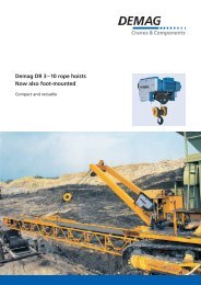
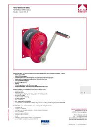
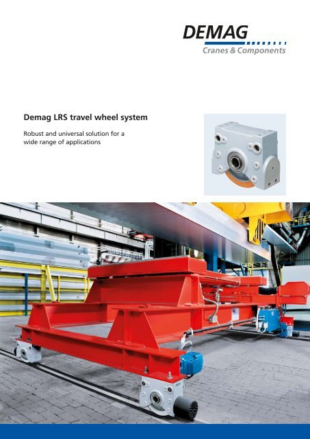
<strong>Demag</strong> <strong>LRS</strong> <strong>travel</strong> <strong>wheel</strong> <strong>system</strong><br />
Robust and universal solution for a<br />
wide range of applications
2<br />
<strong>Demag</strong> <strong>LRS</strong> 200 / <strong>LRS</strong> 250 / <strong>LRS</strong> 350 <strong>travel</strong> <strong>wheel</strong> <strong>system</strong> –<br />
the simple solution for <strong>travel</strong> speeds up to 240 m/min<br />
No need for additional design work, tailored to<br />
meet your needs and ready to install<br />
Using the <strong>Demag</strong> <strong>LRS</strong> <strong>travel</strong> <strong>wheel</strong> <strong>system</strong>, you can meet<br />
your drive requirements quickly and reliably for transport,<br />
feed, transfer or merge applications. We can supply you<br />
with the right <strong>travel</strong> <strong>wheel</strong>s and drive units also for your<br />
application: ready for installation, of proven design and<br />
attractively priced – from stock.<br />
39194-1<br />
The <strong>Demag</strong> <strong>LRS</strong> <strong>system</strong> is suitable for <strong>wheel</strong>s loads up<br />
to 6500 kg and <strong>travel</strong> speeds up to 240 m/min. Simple<br />
selection of the components makes it the ideal assembly<br />
for engineers who want to build their own solution for<br />
a wide variety of <strong>travel</strong> applications.<br />
The extremely robust spheroidal-graphite cast block housing<br />
has five precisely machined connecting surfaces and<br />
offers a range of connection variants. They are designed<br />
for top connection as standard. The required high-tensile<br />
bolt connections included in the scope of delivery are<br />
zinc-coated to provide a special surface protection.
Centre bore holes in the top connection arrangement<br />
eliminate the need for time-consuming re-alignment<br />
when an <strong>LRS</strong> unit is replaced. Alternatively the <strong>LRS</strong> <strong>system</strong><br />
can also be adapted to your superstructure by means of a<br />
pin connection. For this purpose, we also offer a pin<br />
connection set.<br />
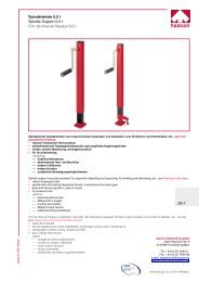
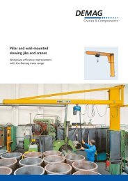
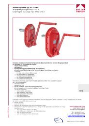
<strong>LRS</strong>...A spheroidal-graphite cast-iron<br />
<strong>travel</strong> <strong>wheel</strong> with two flanges<br />
The <strong>travel</strong> <strong>wheel</strong> designs<br />
Two <strong>travel</strong> <strong>wheel</strong> designs are<br />
available:<br />
■■ spheroidal graphite cast iron <strong>travel</strong><br />
<strong>wheel</strong> with two flanges and<br />
■■ <strong>travel</strong> <strong>wheel</strong> with a Hydropur tyre.<br />
Thanks to the integrated graphite<br />
nodules, the spheroidal-graphite cast<br />
iron <strong>wheel</strong> is self-lubricating and<br />
offers high resistance to wear and<br />
low rolling resistance. It also features<br />
effective damping characteristics for<br />
smooth <strong>travel</strong> that is particularly<br />
gentle on the track. 10 % of the<br />
permissible load capacity can be<br />
accommodated as axial force by<br />
the <strong>wheel</strong> flanges.<br />
<strong>LRS</strong>...F <strong>travel</strong> <strong>wheel</strong> with Hydropur<br />
tyre<br />
The <strong>travel</strong> <strong>wheel</strong> featuring a Hydropur<br />
tyre is particularly suitable for highly<br />
dynamic applications (high acceleration,<br />
friction-<strong>wheel</strong> <strong>travel</strong> drives, etc.)<br />
due to its high friction coefficient. Its<br />
good damping characteristics provide<br />
for quiet operation.<br />
The drive<br />
Above all, <strong>Demag</strong> offset and angular<br />
geared motors are suitable as <strong>travel</strong><br />
drives. With a hollow shaft featuring<br />
involute splines, the gearbox is connected<br />
to the <strong>LRS</strong> <strong>system</strong> by means<br />
of a shaft-mounted <strong>system</strong> and an<br />
optimised torque bracket. Depending<br />
on the mass to be moved and the<br />
The <strong>LRS</strong> <strong>system</strong> requires virtually no maintenance and can<br />
be operated at temperatures from –10 to +40 °C. The<br />
primer coat in RAL 7001 will also accept a paint finish,<br />
enabling you to paint the <strong>LRS</strong> <strong>system</strong> as you wish.<br />
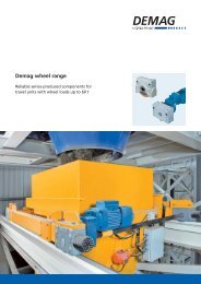
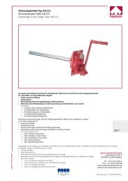
Ground clearance<br />
<strong>LRS</strong> side view shows good ground<br />
clearance<br />
required <strong>travel</strong> speed, various gearbox<br />
sizes with correspon ding <strong>travel</strong><br />
motors are available. All <strong>travel</strong> <strong>wheel</strong>s<br />
feature splined hubs to DIN 5480.<br />
The <strong>LRS</strong> <strong>system</strong> offers good ground<br />
clearance, which is particularly<br />
important for ground-level driven<br />
<strong>travel</strong> units running on rails. Drives<br />
or a rotary encoder can also be<br />
retro-fitted at any time.<br />
3
h4<br />
h1A<br />
4<br />
Your advantages at a glance<br />
Versatile modular <strong>system</strong><br />
■■ Three sizes: <strong>LRS</strong> 200, <strong>LRS</strong> 250 and <strong>LRS</strong> 350<br />
■■ Push <strong>travel</strong> or with standard <strong>travel</strong> drives,<br />
as an individual or central drive arrangement<br />
■■ Can also be extended quickly and inexpensively<br />
at a later date<br />
■■ Optional fittings<br />
■■ horizontal guide<br />
■■ buffers<br />
■■ pin connection set<br />
■■ rail sweeping <strong>system</strong><br />
■■ Laser alignment device<br />
b1<br />
b2<br />
d1<br />
d2<br />
Practical design<br />
■■ Particularly robust thanks to innovative design<br />
■■ Good ground clearance<br />
■■ Maintenance-free <strong>travel</strong> <strong>wheel</strong> bearing arrangement<br />
Simple handling from the start<br />
■■ Simple and understandable documentation<br />
■■ Simple selection using tables or menu-guided<br />
software tools<br />
■■ CAD files of the individual components facilitate<br />
design of your application<br />
■■ Rapid installation<br />
Performance for your needs<br />
■■ Inexpensive solution for your <strong>travel</strong> application<br />
■■ Standard product guarantees short delivery times<br />
with high availability<br />
■■ Consistently high quality thanks to series production<br />
hF<br />
h4<br />
System expertise<br />
■■ One contact partner for the entire <strong>travel</strong> unit<br />
■■ Decades of experience in <strong>travel</strong> unit design<br />
h1F<br />
b1<br />
b2<br />
d1
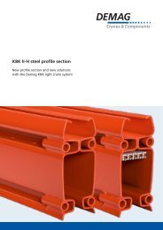
Load capacity dependent on the <strong>travel</strong> speed<br />
The specified <strong>wheel</strong> loads refer to speeds of up to<br />
100 m/min. At higher speeds – up to 240 m/min – the<br />
<strong>wheel</strong> load has to be reduced. If <strong>travel</strong> <strong>wheel</strong>s with<br />
Hydropur tyres are operated under load for longer<br />
periods of time at standstill (> 2 hours), their load<br />
capacity is reduced by 50 % due to the deformation<br />
that occurs.<br />
Load capacity Size<br />
Load capacity in kg<br />
Travel speed in m/min<br />
<strong>LRS</strong> 200 <strong>LRS</strong> 250 <strong>LRS</strong> 350<br />
Spheroidal-graphite cast-iron flanged <strong>wheel</strong> (<strong>LRS</strong>... A) 2500 kg 3500 kg 6500 kg<br />
Travel <strong>wheel</strong> with Hydropur-tyre (<strong>LRS</strong>... F) 1) 1200 kg 1700 kg 3000 kg<br />
39227<br />
1) The specified load capacities of the <strong>travel</strong> <strong>wheel</strong>s<br />
with tyres apply for an ambient temperature of<br />
20 °C. The load capacity decreases at higher<br />
temperatures by 10 % for every 10°<br />
5
6<br />
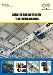
For a wide range of requirements and applications<br />
The <strong>Demag</strong> <strong>LRS</strong> <strong>travel</strong> <strong>wheel</strong> <strong>system</strong> quickly provides you with efficient solutions for a wide variety of requirements.<br />
For example ...<br />
... for transfer carriages<br />
In addition to many other possible designs, two standard<br />
individual drives power this rail-guided four-<strong>wheel</strong><br />
carriage.<br />
39185-1 39185-4<br />
39185-3<br />
... for sliding gates<br />
This gate is guided by spheroidal-graphite cast-iron<br />
<strong>travel</strong> <strong>wheel</strong>s with flanges on a rail. An angular geared<br />
motor serves as a particularly space-saving drive for this<br />
appli cation.<br />
... for building elements such as roofs, walls, floors<br />
Travel <strong>wheel</strong>s fitted with Hydropur tyres guarantee<br />
smooth <strong>travel</strong> characteristics. Two individual drives ensure<br />
smooth <strong>travel</strong> – even for large spans. The horizontal<br />
guide rollers provide reliable guidance of your structure.<br />
39185-2<br />
... for workshop cranes<br />
of portal design fitted with four <strong>LRS</strong> <strong>travel</strong> <strong>wheel</strong>s units<br />
with Hydropur tyres guarantee that loads are moved by<br />
hand quietly and with ease.
39185-6<br />
... for turning devices<br />
The installation shown here features a stationary <strong>LRS</strong><br />
<strong>system</strong> used as a central drive arrangement. The high<br />
friction values required in such appli cations, are achieved<br />
by means of <strong>travel</strong> <strong>wheel</strong>s fitted with Hydropur tyres.<br />
The opposite bearing arrangement also consists of an<br />
<strong>LRS</strong> <strong>system</strong>.<br />
39185-7<br />
... for suspension cranes, bridge viewing devices,<br />
cleaning platforms etc.<br />
<strong>LRS</strong> <strong>system</strong>s with <strong>travel</strong> <strong>wheel</strong>s featuring Hydropur tyres<br />
as friction <strong>wheel</strong> <strong>travel</strong> drives can be adapted to your<br />
specific design requirements.<br />
39185-8<br />
… for sweep arms in sewage treatment plants<br />
The sweep arm is driven by an <strong>LRS</strong> <strong>system</strong> which is fitted<br />
with Hydropur tyres and runs on a concrete surface at<br />
ground level. The arm rotates over a large radius and is<br />
guided by a central pin arrangement.<br />
39185-5<br />
... for theatre decoration and large sets<br />
Four-<strong>wheel</strong> carriages featuring <strong>travel</strong> <strong>wheel</strong>s fitted with<br />
Hydropur tyres ensure that stage elements are moved<br />
quickly and silently throughout the performance thanks<br />
to motions performed by hand at ground level.<br />
7
8<br />
Ideal for four-<strong>wheel</strong> carriages and other design solutions<br />
Optimum combination<br />
The <strong>Demag</strong> <strong>LRS</strong> <strong>travel</strong> <strong>wheel</strong> <strong>system</strong> and line-fed<br />
<strong>Demag</strong> geared <strong>travel</strong> motors offer unbeatable benefits:<br />
They are perfectly matched and of compact design;<br />
they offer outstanding reliability and are easy to install.<br />
The <strong>LRS</strong> <strong>travel</strong> <strong>wheel</strong> <strong>system</strong> is not only ideally suited<br />
for rail-mounted, driven four-<strong>wheel</strong> carriages. Above all,<br />
it enables you to create your own design solutions.<br />
The standard individual drive arrangement consists of<br />
■■ a pole-changing ZBF <strong>travel</strong> motor with an offset<br />
gearbox. The geared motor features IP 54 enclosure.<br />
■■ a shaft which connects the <strong>LRS</strong> and the gearbox by<br />
means of its splined profile. The unused motor-side<br />
shaft end can be fitted with the shaft protection<br />
included in the supply.<br />
■■ a torque bracket as well as the required installation<br />
material.<br />
Whether your planned design includes a motor that<br />
drives two <strong>travel</strong> <strong>wheel</strong>s (central drive arrangement),<br />
or separately driven <strong>travel</strong> <strong>wheel</strong>s (two single drives) –<br />
<strong>Demag</strong> <strong>travel</strong> drive solutions from the modular <strong>system</strong><br />
are available to meet your particular needs. The <strong>Demag</strong><br />
torque bracket also enables variable connection of the<br />
geared motor to the <strong>travel</strong> <strong>wheel</strong> <strong>system</strong>. Whether arranged<br />
on their side, upright or stepped at angles,<br />
<strong>Demag</strong> <strong>travel</strong> drives can be used for individual solutions<br />
that can be adapted to meet specific requirements.<br />
Two individual drives<br />
39236
Compact, strong and precise<br />
The torque bracket design ensures that the drive torque is<br />
transferred from the gearbox to the <strong>LRS</strong> <strong>system</strong> without<br />
any radial forces.<br />
<strong>Demag</strong> ZBF <strong>travel</strong> motors are fly<strong>wheel</strong> drives, which<br />
guarantee smooth acceler ation and braking characteristics<br />
in line-fed operation.<br />
With a wide, finely graduated transmission ratio range,<br />
the offset gearbox integrated into the compact direct<br />
drive provides good ground clearance. The spur <strong>wheel</strong><br />
arrangement in the parallel-shaft gearbox results in a<br />
favourable dimension between the input and output<br />
shafts, which also makes it possible to implement a<br />
central drive arrangement.<br />
40030-16 40030-6<br />
A central drive shaft set can be ordered in two basic<br />
lengths for central drive arrangements.<br />
The set includes:<br />
■■ a connecting shaft<br />
■■ a splined shaft connector<br />
■■ installation material and shaft protection.<br />
The connecting shaft as well as the shaft protection tube<br />
can be shortened when fitted to achieve individual track<br />
gauge dimensions. Central drive shaft sets are available for<br />
track gauge dimensions up to 1,500 mm and 2,900 mm.<br />
Central drive arrangement<br />
9
10<br />
Find the right drive for your application<br />
The selection tables show standard drives for line-fed<br />
operation (400 V, 50 Hz) for typical speeds. Drives for<br />
inverter operation, other or higher speeds on request.<br />
To find the right drive for your application, proceed<br />
as follows:<br />
■■ determine the total mass to be moved<br />
■■ select the size, <strong>travel</strong> <strong>wheel</strong> design and number of<br />
<strong>travel</strong> <strong>wheel</strong>s (consider the maximum load capacity<br />
of each <strong>LRS</strong>)<br />
■■ determine the drive type:<br />
individual or central drive arrangement<br />
■■ the total mass is driven by one drive on a four-<strong>wheel</strong><br />
carriage with a central drive arrangement<br />
■■ half of the total mass is driven by one drive on a<br />
four-<strong>wheel</strong> carriage with single-drive arrangements<br />
■■ The drive combinations (11-65) corresponding to the<br />
required <strong>travel</strong> speed and mass can be read from<br />
the tables. Simply use this number to find the selected<br />
combination in the order list (see page 21).<br />
* Figures in brackets indicate the low <strong>travel</strong> speed of the pole-changing motor<br />
** Central drive arrangement not possible<br />
Drives for spheroidal-graphite cast-iron <strong>wheel</strong>s with flanges<br />
<strong>LRS</strong> 200 A, Ø 175 mm, R max = 2500 kg<br />
Speed v in m/min<br />
12.5 (3.1)* 40 (10)* 80 (20)*<br />
...<br />
3000<br />
4000<br />
5000<br />
6000<br />
7000<br />
11** 13**<br />
15<br />
8000<br />
14<br />
9000<br />
10000<br />
11000<br />
12000<br />
13000<br />
14000<br />
15000<br />
16000<br />
12<br />
Drive combination Gearbox Motor<br />
Mass per drive in kg<br />
11 AMK 20 TD ZBF 63 A 8/2<br />
12 AMK 30 TD ZBF 71 A 8/2<br />
13 AMK 20 TD ZBF 80 A 8/2<br />
14 AMK 30 DD ZBF 90 B 8/2<br />
15 AMK 30 DD ZBF 100 A 8/2<br />
Drives for <strong>travel</strong> <strong>wheel</strong>s with Hydropur tyres<br />
Mass per drive in kg<br />
<strong>LRS</strong> 200 F, Ø 200 mm, R max = 1200 kg<br />
...<br />
1000<br />
1500<br />
2000<br />
2500<br />
3000<br />
3500<br />
4000<br />
4500<br />
5000<br />
5500<br />
6000<br />
6500<br />
7000<br />
Speed v in m/min<br />
12.5 (3.1)* 40 (10)* 80 (20)*<br />
21<br />
22** 24<br />
Drive combination Gearbox Motor<br />
21 AMK 30 TD ZBF 63 A 8/2<br />
22 AMK 20 TD ZBF 71 A 8/2<br />
23 AMK 30 DD ZBF 90 B 8/2<br />
24 AMK 30 DD ZBF 90 B 8/2<br />
25 AMK 30 DD ZBF 100 A 8/2<br />
23<br />
25
Mass per drive in kg<br />
Mass per drive in kg<br />
<strong>LRS</strong> 250 A, Ø 220 mm, R max = 3500 kg<br />
...<br />
3000<br />
4000<br />
5000<br />
6000<br />
7000<br />
8000<br />
9000<br />
10000<br />
11000<br />
12000<br />
13000<br />
14000<br />
15000<br />
16000<br />
Speed v in m/min<br />
12.5 (3.1)* 40 (10)* 80 (20)*<br />
31** 33**<br />
32 34<br />
Drive combination Gearbox Motor<br />
35**<br />
31 AMK 30 TD ZBF 63 A 8/2<br />
32 AMK 40 TD ZBF 71 A 8/2<br />
33 AMK 30 DD ZBF 90 B 8/2<br />
34 AMK 40 DD ZBF 100 A 8/2<br />
35 AMK 30 DD ZBF 100 A 8/2<br />
<strong>LRS</strong> 350 A, Ø 315 mm, R max = 6500 kg<br />
<strong>LRS</strong> 250 F, Ø 250 mm, R max = 1700 kg <strong>LRS</strong> 350 F, Ø 350 mm, R max = 3000 kg<br />
...<br />
1000<br />
1500<br />
2000<br />
2500<br />
3000<br />
3500<br />
4000<br />
4500<br />
5000<br />
5500<br />
6000<br />
6500<br />
7000<br />
Speed v in m/min<br />
12.5 (3.1)* 40 (10)* 80 (20)*<br />
41** 43** 45**<br />
42 44<br />
Drive combination Gearbox Motor<br />
41 AMK 30 TD ZBF 63 A 8/2<br />
42 AMK 40 TD ZBF 71 A 8/2<br />
43 AMK 30 DD ZBF 80 A 8/2<br />
44 AMK 40 DD ZBF 90 B 8/2<br />
45 AMK 30 DD ZBF 100 A 8/2<br />
Mass per drive in kg<br />
...<br />
9000<br />
10000<br />
11000<br />
12000<br />
13000<br />
14000<br />
15000<br />
16000<br />
17000<br />
18000<br />
19000<br />
20000<br />
21000<br />
22000<br />
Speed v in m/min<br />
12.5 (3.1)* 40 (10)* 80 (20)*<br />
52 54<br />
Drive combination Gearbox Motor<br />
52 / 52B ADK 50 TD ZBF 80 A 8/2<br />
54 / 54B ADK 50 DD ZBF 100 A 8/2<br />
55 / 55B ADK 50 DD ZBF 132 A 8/2<br />
B = Drive combination for pin connection<br />
Mass per drive in kg<br />
...<br />
5000<br />
5500<br />
6000<br />
6500<br />
7000<br />
7500<br />
8000<br />
8500<br />
9000<br />
9500<br />
10000<br />
10500<br />
11000<br />
B = Drive combination for pin connection<br />
Speed v in m/min<br />
55<br />
12.5 (3.1)* 40 (10)* 80 (20)*<br />
62<br />
64 65<br />
Drive combination Gearbox Motor<br />
62 / 62B ADK 50 TD ZBF 80 A 8/2<br />
64 / 64B ADK 50 TD ZBF 90 B 8/2<br />
65 / 65B ADK 50 DD ZBF 132 A 8/2<br />
11
12<br />
Dimensions<br />
Sizes <strong>LRS</strong> 200 / <strong>LRS</strong> 250 / <strong>LRS</strong> 350<br />
<strong>LRS</strong> 200<br />
<strong>LRS</strong> 250<br />
<strong>LRS</strong> 350<br />
<strong>LRS</strong> … A<br />
Wheel b1 b2 d1 d2 Weight [kg]<br />
A 52 70 175 200 15.3<br />
F – 70 200 – 15.1<br />
A 55 80 220 250 27.6<br />
F – 80 250 – 26.7<br />
A 65 95 315 345 63.0<br />
F – 110 350 – 65.0<br />
<strong>LRS</strong> … F<br />
d3 6g/7H d4 F8 d5 d6 H13 d7 1) h A h F h4 A h4 F h2 h3 l1 l2 l3 w1 w2 w3<br />
<strong>LRS</strong> 200 N35 x 2 x 16 21 M12 10.2 M12 x 45 204.5 217 100 112.5 72 77 250 175 175 138 126 80<br />
<strong>LRS</strong> 250 N45 x 2 x 21 30 M16 14 M16 x 55 255 270 100 115 90 97 306 220 220 156 138 85<br />
<strong>LRS</strong> 350 N50 x 2 x 24 40 M16 14 M20 x 80 349.5 367 140 157.5 80 141 450 370 320 200 186 100<br />
1) Length of the top-connection bolt
Driven <strong>LRS</strong> 200 / <strong>LRS</strong> 250 / <strong>LRS</strong> 350 with offset gearbox and ZBF <strong>travel</strong> motor<br />
<strong>LRS</strong> 200<br />
<strong>LRS</strong> 250<br />
Size Drive combination<br />
Ground clearance<br />
Gearbox Motor A F<br />
l hG w AC AG<br />
xA xF AMK 20<br />
AMK 30<br />
AMK 30<br />
AMK 40<br />
<strong>LRS</strong> 350 ADK 50<br />
ZBF 63/71 11 22 228 131 608 140 103 17.5 30<br />
ZBF 80 13 – 238 131 664 157 103 9 21.5<br />
ZBF 63/71 12 21 253 160 615 140 103 7.5 20<br />
ZBF 90B/100 14, 15 23, 25 281 160 715 196 133 -10.5 2<br />
ZBF 63 31 41 253 160 641 140 103 30 45<br />
ZBF 80/90A – 43 263 160 697 157 103 30 45<br />
ZBF 90B/100 33, 35 45 281 160 741 196 133 12 27<br />
ZBF 71 32 42 272 190 650 140 103 15 30<br />
ZBF 90B/100 34 44 300 190 750 196 133 12 27<br />
ZBF 80 52 62 312 250 769 157 103 16.5 34<br />
ZBF 90B/100 54 64 330 250 813 196 133 16.5 34<br />
<strong>LRS</strong> with standard drive combination<br />
ZBF 132 55 65 363 260 955 260 173 16.5 34<br />
Size <strong>LRS</strong> 200 Size <strong>LRS</strong> 250 Size <strong>LRS</strong> 350<br />
13
Options and accessories from the <strong>Demag</strong> modular drive <strong>system</strong><br />
Thanks to its modular design, you can benefit from the<br />
entire <strong>Demag</strong> drives product range. In addition to offset<br />
gearboxes, you can also select angular gearboxes for<br />
special mounting requirements, for example.<br />
<strong>Demag</strong> pole-changing <strong>travel</strong> motors for line-fed<br />
operation are provided as standard drives. We can<br />
also supply you with the appropriate drive for inverter<br />
operation, too. The proven <strong>Demag</strong> KB conical-rotor<br />
motors for starting and stopping applications can also<br />
be fitted to the gearboxes.<br />
Our sales engineers and project engi neering departments<br />
are pleased to help you with these special designs or for<br />
masses and <strong>travel</strong> speeds other than those shown in the<br />
tables – up to 240 m/min.<br />
39886-10 39886-6<br />
14
15<br />
Options and accessories at a glance<br />
Pin connection set<br />
consisting of:<br />
■■ pins<br />
■■ washers and retaining rings<br />
■■ threaded adjusting pins and nuts<br />
Bore hole template for torque<br />
arm attachment for driven<br />
version<br />
Order no. w6min w7max dB d7 d9 I6 h5<br />
<strong>LRS</strong> 200 301 221 84 8 158 21 h8/D9 M10 50 175 20<br />
<strong>LRS</strong> 250 301 321 84 10 185 30 h8/D9 M12 60 220 25<br />
<strong>LRS</strong> 350 1) 301 421 84 10 230 40 h8/D9 M12 80 400 50<br />
1) Pin connection set not required for <strong>LRS</strong> 350 with standard drive combination<br />
h6 h7 h8 l7 l8 l9 d8<br />
<strong>LRS</strong> 200 41 10 68.5 58.5 92 77.5 M8<br />
<strong>LRS</strong> 250 56 12 90 75 110 97.5 M10<br />
<strong>LRS</strong> 350 Bore hole template not required for <strong>LRS</strong> 350 with standard drive combination
Buffer set<br />
consisting of:<br />
■■ DPZ cellular-foam buffer<br />
■■ threaded pin<br />
■■ spacer elements<br />
Order no. Buffer lP dP dG w8 w9<br />
<strong>LRS</strong> 200<br />
301 710 84 DPZ 100 100 100 M12 12.5 20<br />
<strong>LRS</strong> 250<br />
<strong>LRS</strong> 350 301 711 84 DPZ 130 120 130 M12 16 25<br />
Central drive set<br />
consisting of:<br />
■■ splined-profile shaft<br />
■■ coupling<br />
■■ shaft protection<br />
■■ washers and retaining rings<br />
Track centre dimension up to 1500 mm up to 2900 mm<br />
<strong>LRS</strong> 200 301 256 84 301 257 84<br />
<strong>LRS</strong> 250 301 356 84 301 357 84<br />
<strong>LRS</strong> 350 301 456 84 301 457 84<br />
Laser alignment device<br />
to adjust two <strong>LRS</strong> units, to avoid skewing.<br />
The set includes:<br />
■■ laser<br />
■■ slot aperture and target marker<br />
■■ adapter mounting for universal application<br />
with <strong>Demag</strong> DRS and <strong>Demag</strong> <strong>LRS</strong> <strong>system</strong>s<br />
Order no.: 752 100 44<br />
16 16
1)<br />
1) When a roller guide arrangement is used,<br />
ensure that it does not collide with the rail<br />
attachment.<br />
Rail sweeping <strong>system</strong><br />
(up to 120 mm rail width) consisting of:<br />
■■ Rail sweep bracket for attachment to the <strong>LRS</strong><br />
face end, also in connection with buffer set<br />
(DPZ 100 only)<br />
■■ Brush with polyamide fibres (Ø 0.4 mm)<br />
Travel <strong>wheel</strong> centre Horizontal guide rollers<br />
consisting of:<br />
Order no. lb h6 h7 <strong>LRS</strong> 200 A<br />
41.5 87.5<br />
301 732 84 202<br />
<strong>LRS</strong> 200 F 54 100<br />
<strong>LRS</strong> 250 A<br />
64 110<br />
230<br />
<strong>LRS</strong> 250 F 79 125<br />
301 733 84<br />
<strong>LRS</strong> 350 A<br />
111.5 157.5<br />
302<br />
<strong>LRS</strong> 350 F 129 175<br />
■■ roller bracket for fitting to <strong>LRS</strong> end face<br />
■■ mounting screws<br />
■■ Polyamide damping element (only for <strong>travel</strong><br />
<strong>wheel</strong>s with Hydropur tyres)<br />
The permissible horizontal force of an <strong>LRS</strong> <strong>system</strong><br />
fitted with a roller guide arrangement must not<br />
exceed 20% of the permissible <strong>wheel</strong> load.<br />
Order no. d l H m a w H n b<br />
<strong>LRS</strong> 200 A 752 210 44 62 192 155 110 60 25 30-70<br />
<strong>LRS</strong> 200 F 301 210 84 52 192 155 124 60 25 62-82<br />
<strong>LRS</strong> 250 A 752 510 44 72 230 189 137 72 29 30-80<br />
<strong>LRS</strong> 250 F 301 310 84 72 230 189 154 72 29 64-84<br />
<strong>LRS</strong> 350 A 753 010 44 80 250 265 191 80 33 40-90<br />
<strong>LRS</strong> 350 F 301 410 84 80 300 300 208 80 33 90-136<br />
17
18<br />
Selection and order examples –<br />
<strong>Demag</strong> <strong>LRS</strong> <strong>travel</strong> <strong>wheel</strong> <strong>system</strong> and accessories<br />
Example 1<br />
for a non-driven four-<strong>wheel</strong> carriage<br />
A mass of 4,000 kg has to be moved on a concrete<br />
surface. This results in selection of a <strong>travel</strong> <strong>wheel</strong> with<br />
a Hydropur tyre. The mass to be moved is distributed<br />
over four <strong>wheel</strong>s. The <strong>wheel</strong> load therefore amounts to<br />
1,000 kg. Therefore, the recommended choice is <strong>LRS</strong><br />
size 200 (permissible <strong>wheel</strong> load 1,200 kg). The standard<br />
top connection is ideal for connecting the <strong>LRS</strong> units to<br />
the superstructure.<br />
Order list:<br />
4 x <strong>LRS</strong> 200 F Order no. 301 200 84<br />
Example 2<br />
for a four-<strong>wheel</strong> carriage with a central drive<br />
arrangement<br />
A mass of 12,500 kg has to be moved with a main <strong>travel</strong><br />
speed of 12.5 m/min. The positioning speed amounts<br />
to 3.1 m/min. The flat rails are laid with a track gauge<br />
dimension of 2.80 m. Due to the <strong>wheel</strong> load of 3,125 kg,<br />
spheroidal-graphite cast-iron <strong>travel</strong> <strong>wheel</strong>s in size 250<br />
are selected (permissible <strong>wheel</strong> load 3,500 kg). In order<br />
to keep the control <strong>system</strong> requirements to a minimum<br />
and still maintain simultaneous operation, a central drive<br />
arrangement is to be employed. This means that one<br />
motor has to move the entire mass of 12,500 kg.<br />
The appropriate drive with the drive combination 32 is<br />
selected from the drive selection table for the <strong>LRS</strong> 250 A<br />
(page 10). Buffers on the <strong>LRS</strong> units protect the <strong>travel</strong> unit<br />
in an emergency situation.<br />
Order list:<br />
4 x <strong>LRS</strong> 250 A Order no. 301 301 84<br />
1 x drive with drive combination 32, AMK 40 TD ZBF<br />
71 A8/2 pole-changing geared motor incl. journal<br />
shaft, shaft protection, torque bracket and assembly<br />
material<br />
Order no. 858 232 46<br />
1 x central drive set 2900 for max. track gauge 2.90 m<br />
Order no. 301 357 84<br />
4 x buffer set Order no. 301 710 84
Example 3<br />
for a four-<strong>wheel</strong> carriage with two individual<br />
drives<br />
A mass of 6,000 kg has to be moved with a main <strong>travel</strong><br />
speed of 80 m/min on flat rails. Since quiet operation<br />
with gentle handling of the load is required, this results<br />
in selection of <strong>travel</strong> <strong>wheel</strong>s with Hydropur tyres.<br />
The <strong>wheel</strong> load amounts to 1,500 kg. This results in<br />
selection of <strong>LRS</strong> 250 F (permissible <strong>wheel</strong> load 1,700 kg).<br />
For this <strong>travel</strong> speed, the selection table (page 10) shows<br />
a geared motor that can move a mass of up to 4,000 kg<br />
(drive combination 45). Two geared motors (individual<br />
drives) are selected with drive combination 45.<br />
39185-1<br />
Note:<br />
The drives have to be arranged opposite each other in<br />
order to avoid any skewing. Two horizontal guide roller<br />
arrangements are also needed to ensure that the carriage<br />
is guided on the rails. The optional pin connection set is<br />
selected to connect the <strong>LRS</strong> units to the superstructure.<br />
Order list:<br />
4 x <strong>LRS</strong> 250 F Order no. 301 300 84<br />
4 x pin connection set Order no. 301 321 84<br />
2 x geared motor drive combination 45,<br />
AMK 30 DD ZBF 100 A8/2 pole-changing geared<br />
motor incl. journal shaft, shaft protection, torque<br />
bracket and assembly material<br />
Order no. 858 245 46<br />
2 x horizontal guide rollers Order no. 301 310 84<br />
19
20<br />
From CAD model and design support via the Internet<br />
to convenient online ordering<br />
Simple integration thanks to CAD files<br />
To make it easy for you to integrate the selected <strong>LRS</strong><br />
components into your individual designs, we offer you<br />
2D and 3D CAD files in various formats via the following<br />
Internet address: www.lrs.demagcranes.com. You<br />
select your CAD format when you have selected the<br />
required components in a list.<br />
The following formats are available:<br />
2D-CAD-Files<br />
■■ DXF 1)<br />
■■ DWG<br />
3D-CAD-Files<br />
■■ IGES<br />
■■ STEP<br />
■■ Pro/Engineer (2001)<br />
Dimension sheets<br />
■■ PDF<br />
1) The DXF viewer is available free of charge and enables<br />
you to view the files<br />
Online connection to the <strong>Demag</strong> Shop <strong>system</strong><br />
Benefit from the advantages of online ordering for<br />
selected <strong>LRS</strong> components at www.demag-shop.com<br />
You can either reserve or order the components you<br />
wish. At the same time, you can specify both the delivery<br />
period as well as the shipping method. When you have<br />
ordered the components, we immediately advise our<br />
order number as well as the calculated delivery date.
Fax service +49 (0) 2335 92-2406<br />
Your enquiry fax for the <strong>Demag</strong> <strong>LRS</strong> <strong>travel</strong> <strong>wheel</strong> <strong>system</strong> –<br />
the universal solution for many applications.<br />
<strong>Demag</strong> Cranes & Components GmbH<br />
Drives Product Management (1312)<br />
Postfach 67<br />
58286 Wetter/Germany<br />
I would like<br />
I am ordering<br />
Price information<br />
Quotation<br />
<strong>LRS</strong> 200 components Order no. Qty<br />
<strong>LRS</strong> 200 A 301 201 84<br />
<strong>LRS</strong> 200 F 301 200 84<br />
Pin connection set 301 221 84<br />
Central drive set – 1500 mm 301 256 84<br />
Central drive set – 2900 mm 301 257 84<br />
Buffer set 301 710 84<br />
Horizontal roller guide <strong>LRS</strong> 200 A 752 210 44<br />
Horizontal roller guide <strong>LRS</strong> 200 F 301 210 84<br />
Rail sweeping <strong>system</strong> 301 732 84<br />
Laser alignment device 752 100 44<br />
<strong>LRS</strong> 250 components Order no. Qty<br />
<strong>LRS</strong> 250 A 301 301 84<br />
<strong>LRS</strong> 250 F 301 300 84<br />
Pin connection set 301 321 84<br />
Central drive set – 1500 mm 301 356 84<br />
Central drive set – 2900 mm 301 357 84<br />
Buffer set 301 710 84<br />
Horizontal roller guide <strong>LRS</strong> 200 A 752 510 44<br />
Horizontal roller guide <strong>LRS</strong> 200 F 301 310 84<br />
Rail sweeping <strong>system</strong> 301 733 84<br />
Laser alignment device 752 100 44<br />
<strong>LRS</strong> 350 components Order no. Qty<br />
<strong>LRS</strong> 350 A 301 401 84<br />
<strong>LRS</strong> 350 F 301 400 84<br />
Pin connection set 301 421 84<br />
Central drive set – 1500 mm 301 456 84<br />
Central drive set – 2900 mm 301 457 84<br />
Buffer set 301 710 84<br />
Horizontal roller guide <strong>LRS</strong> 200 A 753 010 44<br />
Horizontal roller guide <strong>LRS</strong> 200 F 301 410 84<br />
Rail sweeping <strong>system</strong> 301 733 84<br />
Laser alignment device 752 100 44<br />
Sent by<br />
Company<br />
P.O. Box / Street<br />
Town / Post code<br />
Contact<br />
Telephone / extension<br />
Telefax<br />
E-mail<br />
Drive combinations Order no. Qty<br />
11 AMK 20 TD ZBF 63 A 8/2 858 211 46<br />
12 AMK 30 TD ZBF 71 A 8/2 858 212 46<br />
13 AMK 20 TD ZBF 80 A 8/2 858 213 46<br />
14 AMK 30 DD ZBF 90 B 8/2 858 214 46<br />
15 AMK 30 DD ZBF 100 A 8/2 858 215 46<br />
21 AMK 30 TD ZBF 63 A 8/2 858 221 46<br />
22 AMK 20 TD ZBF 71 A 8/2 858 222 46<br />
23 AMK 30 DD ZBF 90 B 8/2 858 223 46<br />
24 AMK 30 DD ZBF 90 B 8/2 858 224 46<br />
25 AMK 30 DD ZBF 100 A 8/2 858 225 46<br />
Drive combinations Order no. Qty<br />
31 AMK 30 TD ZBF 63 A 8/2 858 231 46<br />
32 AMK 40 TD ZBF 71 A 8/2 858 232 46<br />
33 AMK 30 DD ZBF 90 B 8/2 858 233 46<br />
34 AMK 40 DD ZBF 100 A 8/2 858 234 46<br />
35 AMK 30 DD ZBF 100 A 8/2 858 235 46<br />
41 AMK 30 TD ZBF 63 A 8/2 858 241 46<br />
42 AMK 40 TD ZBF 71 A 8/2 858 242 46<br />
43 AMK 30 DD ZBF 80 A 8/2 858 243 46<br />
44 AMK 40 DD ZBF 90 B 8/2 858 244 46<br />
45 AMK 30 DD ZBF 100 A 8/2 858 245 46<br />
Drive combinations for top connection Order no. Qty<br />
52 ADK 50 TD ZBF 80 A 8/2 858 252 46<br />
54 ADK 50 DD ZBF 100 A 8/2 858 254 46<br />
55 ADK 50 DD ZBF 132 A 8/2 858 255 46<br />
62 ADK 50 TD ZBF 80 A 8/2 858 262 46<br />
64 ADK 50 TD ZBF 90 B 8/2 858 264 46<br />
65 ADK 50 DD ZBF 132 A 8/2 858 265 46<br />
Drive combinations for top connection Order no. Qty<br />
52B ADK 50 TD ZBF 80 A 8/2 858 257 46<br />
54B ADK 50 DD ZBF 100 A 8/2 858 258 46<br />
55B ADK 50 DD ZBF 132 A 8/2 858 259 46<br />
62B ADK 50 TD ZBF 80 A 8/2 858 267 46<br />
64B ADK 50 TD ZBF 90 B 8/2 858 268 46<br />
65B ADK 50 DD ZBF 132 A 8/2 858 269 46<br />
21
Complete industrial drive solutions – from <strong>wheel</strong>s to inverters<br />
<strong>Demag</strong> geared motors<br />
■■ as helical geared motors from 90 to 5800 Nm<br />
■■ as angular geared motors from 120 to 12000 Nm<br />
■■ as offset geared motors for 130 to 11500 Nm<br />
with cylindrical-rotor motors from 0.18 to 45 kW<br />
<strong>Demag</strong> conical-rotor brake motors<br />
for increased requirements such as extremely high<br />
switching frequencies and braking operation for outputs<br />
from 0.37 to 42 kW<br />
<strong>Demag</strong> microspeed drives<br />
with conical-rotor motors; for high speed stages and<br />
positioning with high stopping accuracy; speed ratios<br />
up to 500:1<br />
<strong>Demag</strong> Dedrive Compact and Dedrive Pro<br />
frequency inverters<br />
for AC drives with motor shaft outputs up to 560 kW;<br />
control of cylindrical and conical-rotor motors as single<br />
or groups of drives; current loads from 2.4 to 110 A<br />
or 4.2 to 544 A<br />
<strong>Demag</strong> <strong>travel</strong> unit components<br />
Modular <strong>system</strong>s for elements in materials handling installations<br />
and mechanical engineering applications without<br />
the need for any additional design work and production<br />
■■ DRS <strong>wheel</strong> block <strong>system</strong>; many <strong>wheel</strong> variant and<br />
connection possibilities, high performance; from 2.75 t<br />
to 40 t<br />
■■ RS <strong>wheel</strong> block <strong>system</strong>; with sheet-steel housing for<br />
special applications, also in high-temperature range up<br />
to 350 °C<br />
■■ <strong>LRS</strong> <strong>travel</strong> <strong>wheel</strong> <strong>system</strong>; the simple <strong>system</strong> for the<br />
lower load range up to 6.5 t<br />
■■ RAE/RNE <strong>wheel</strong> sets; for integration into hollw-profile<br />
sections or for corner-bearing arrangements; up to 60 t<br />
<strong>Demag</strong> DCL Compact Line<br />
Power feed <strong>system</strong>; designed for currents up to 200 A<br />
(60 % CDF); fitted with up to 7 conductors, as required;<br />
both for supplying mobile consumers with power as well<br />
as for transferring control signals<br />
www.demagcranes.com 0610 EN/DE 213 155 44 701 IS 845<br />
Subject to change. No liability for errors or omissions.<br />
Printed in Germany S+S/300610/1T