DFW-L-E end carriages - Demag Cranes & Components
DFW-L-E end carriages - Demag Cranes & Components
DFW-L-E end carriages - Demag Cranes & Components

Create successful ePaper yourself
Turn your PDF publications into a flip-book with our unique Google optimized e-Paper software.
<strong>DFW</strong>-L-E <strong>end</strong> <strong>carriages</strong><br />
with DRS 112 to 200<br />
010802 EN/DE 203 321 44 714 IS 845.1
Contents<br />
<strong>DFW</strong>-L-E / S<br />
1 <strong>DFW</strong> product description<br />
Page<br />
3<br />
1.1 Application 3<br />
1.2 Modular carriage system 3<br />
1.3 Protection against corrosion, paint finish 3<br />
1.4 Documentation 3<br />
2 Design and mounting information 4<br />
2.1 Steel construction 4<br />
2.2 Types of connection 4<br />
2.3 DRS wheel block system 5<br />
2.4 Adjusting the span 5<br />
2.5 Wind safety catches 6<br />
2.6 Optimizing the travel speed 6<br />
3 Mounting code 7<br />
3.1 Type designation 7<br />
3.2 Order information 7<br />
4 <strong>DFW</strong>-L-E/S <strong>end</strong> <strong>carriages</strong> 8<br />
4.1 Data and dimensions 8<br />
5 <strong>DFW</strong>-L-E/O <strong>end</strong> <strong>carriages</strong> 10<br />
5.1 Data and dimensions 10<br />
6 <strong>DFW</strong>-L-E <strong>end</strong> carriage attachments 12<br />
6.1 End plates 12<br />
6.2 Bolted mounting plates with non-countersunk bore holes<br />
and with countersunk bore holes for <strong>DFW</strong>-L-E/S 14<br />
6.3 Bolted and welded mounting plates for <strong>DFW</strong>-L-E/O 16<br />
6.4 Torque brackets 18<br />
6.5 Buffers and spacers 18<br />
6.6 Guide rollers 18<br />
7 Order form for <strong>DFW</strong>-L-E <strong>end</strong> <strong>carriages</strong> 19<br />
Steel structure Bolted mounting plate Geared motor<br />
Torque bracket<br />
Buffer Wheel block High-tensile For outdoor operation only Wheel block Spacer<br />
End<br />
Non-driven bolted<br />
1x for Ax500 mm<br />
Driven<br />
20332001.eps<br />
2 20332144.p65/010802
1.1 Application<br />
1.2 Modular carriage<br />
system<br />
1.3 Protection against<br />
corrosion<br />
Paint coat<br />
1.4 Documentation<br />
20332144.p65/010802 1 Product description<br />
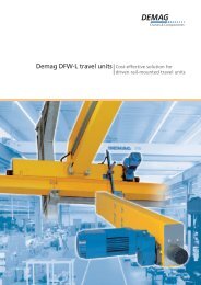
<strong>DFW</strong>-L-E <strong>carriages</strong> are used for steel structures in the crane and lifting equipment<br />
industry and also for applications in related mechanical engineering.<br />
<strong>DFW</strong>-L-E <strong>carriages</strong> are compact, driven, rail-mounted <strong>carriages</strong> for direct connection<br />
to load-bearing structures. In addition to the steel structure part, a torsionally<br />
resistant box section, the <strong>end</strong> carriage includes a driven wheel block for fitting the<br />
gearbox and the motor as well as a non-driven wheel block. The carriage design is<br />
based on the latest principles for steel structures and, even with high loads, has<br />
excellent travelling characteristics due to the fine tolerances of the carriage regarding<br />
track gauge errors, diagonal position and misalignment. Specially adapted heavyduty<br />
motors provide excellent speed/torque characteristics, which ensure smooth<br />
starting for both the unloaded and the loaded carriage.<br />
The following equipment can be combined to form a complete carriage:<br />
Connection<br />
• Carriages with one crane girder connection on the side (standard)<br />
• Carriages with one crane girder connection on the top<br />
Travel unit/travel wheel<br />
• DRS wheel blocks 112, 125, 160, 200 mm<br />
• Max. wheel loads up to 10000 kg<br />
• Wheel bases 2000, 2500, 3150, 4000 mm<br />
Travel drive (drive units fitted either on right-hand or left-hand side)<br />
• AM offset gearboxes<br />
• ZBF travel motors<br />
• MA torque brackets<br />
Buffers<br />
• DPZ Cellular plastic buffers<br />
Protection against corrosion<br />
• Structural steel shot-blasted (Sa2 rust removal factor to DIN 55 928).<br />
• Rust protection with primer paint in RAL 1004 golden yellow (thickness 60 µm)<br />
• Galvanized finish available on request<br />
• Other provisions for corrosion protection available on request.<br />
Paint coat<br />
• A final coat in RAL 1007 daffodil yellow or other colours can be provided on<br />
request.<br />
Travel unit<br />
• Operating instructions 214 362 44<br />
• Component parts list 222 736 44<br />
DRS wheel blocks, gearboxes, travel motors and buffers<br />
• <strong>Demag</strong> DRS wheel block system Volume 1 1) 203 352 44<br />
• Geared motors for travel applications Volume 2 203 355 44<br />
1) required for rating the <strong>end</strong> <strong>carriages</strong><br />
3
2 Design and mounting information<br />
2.1 Steel structure<br />
Steel structure with side connection of main girder<br />
2.2 Types of connection<br />
The steel structure is designed in accordance with DIN 15018, lifting class H2, stress<br />
group B3.<br />
Steel structure characteristics:<br />
• High stability due to enclosed, torsion-resistant box section girder. Great<br />
strength in connection area due to diaphragm plates welded into the carriage.<br />
• Machining on NC machines provides precise positioning of travel wheel axles<br />
with respect to mating surfaces.<br />
• Easy assembly and access. Detachable and anti-shear high-tensile connection<br />
with adjoining structure.<br />
• Optimum travel characteristics. Can be easily exchanged due to accuracy of the<br />
connection geometry. Fine tolerances for track gauge errors, diagonal wheel<br />
position and misalignment are met as a result of the precise alignment and<br />
machining of the connection surfaces.<br />
The carriage can be connected to the structure in the following ways:<br />
• bottom flush (side connection of main girder),<br />
• top flush (side connection of main girder),<br />
• raised (side connection of main girder),<br />
• lowered (side connection of main girder),<br />
• top connection (top connection of main girder),<br />
Steel structure with top connection of main girder<br />
20332002.eps<br />
Bottom flush Top flush Raised Lowered Top connection<br />
20332003.eps<br />
4 20332144.p65/010802
20332144.p65/010802<br />
2.3 DRS wheel blocks<br />
b wheel<br />
b 2<br />
d 1<br />
b rail<br />
d 2<br />
2.4 Adjusting the span<br />
Spacer elements<br />
20332004.eps<br />
Wheel blocks feature:<br />
• Positive travel wheel/shaft connection resulting from the splined shaft section.<br />
Simple, fast assembly and replacement with commercially available tools.<br />
High wheel loads, long service life due to dust-proof anti-friction bearings lubricated<br />
for life.<br />
Simple adjustment of span by re-arranging spacer elements between the wheel<br />
block and the inside of the carriage girder.<br />
Considerably reduced wear on travel wheels (wear indicator) and track rails as a<br />
result of the self-lubricating effect of spheroidal graphite cast iron compared with<br />
steel.<br />
Silent running due to self-damping properties of the travel wheel material.<br />
Travel wheel profile<br />
1) other treads on request<br />
2) max. wheel loads for linear contact (flat rail to DIN 1014 or A rail to DIN 536) dep<strong>end</strong>ing on FEM group, useful rail width and<br />
long travel speed, see catalogue 203 352 44, section 2.6.5<br />
By re-arranging the spacer elements, the span can be adjusted.<br />
d 1<br />
Spacer<br />
elements<br />
[ mm]<br />
T hickness<br />
[ mm]<br />
Max.<br />
adjustment<br />
[ mm]<br />
112<br />
D imensions<br />
in<br />
mm<br />
Max.<br />
wheel<br />
loads<br />
2)<br />
d1d2 b2 Max. bwheel<br />
Standard b 1 ) w heel<br />
[ kg]<br />
112 132 80 60 47, 60<br />
3500<br />
125 150 80 60 47, 60<br />
5000<br />
160 188 89 65 47, 60,<br />
65<br />
7000<br />
200 230 101 65 65 10000<br />
± 6<br />
125± 4<br />
2 and<br />
5<br />
160± 6<br />
200 ± 10<br />
Spacer elements<br />
20332005.eps<br />
5
2 Design and mounting information<br />
2.5 Wind safety catches<br />
2.6 Optimizing the travel<br />
speed<br />
Travel speed (m/min)<br />
125<br />
100<br />
80<br />
63<br />
50<br />
40<br />
31,5<br />
25<br />
20<br />
16<br />
12,5<br />
5<br />
According to accident prevention regulations (UVV, BGV D6 § 14.1 (VBG 9)), cranes<br />
must have their power-driven travelling and slewing movements braked, thus<br />
preventing unint<strong>end</strong>ed movement. According to the regulations UVV 18.2 BGV D6<br />
§ 30.6 (VBG 9), the crane operator must ensure that cranes exposed to the wind are<br />
secured during storms and at the <strong>end</strong> of work.<br />
According to the surface area exposed to the wind, one or two safety catches are<br />
required per crane.<br />
Dep<strong>end</strong>ing on accessibility, the manually operated wind safety catch should be<br />
preferred.<br />
Optimum handling capacity can only be achieved by correctly selecting the working<br />
speeds. For this, the average speed of the individual movements is the determining<br />
factor.<br />
6 7 8 9 10 15 20 25 30<br />
Crane runway length or span (m)<br />
20332008.eps<br />
6 20332144.p65/010802<br />
40<br />
50<br />
100<br />
150<br />
200
3.1 Type designation<br />
3.2 Order information The following information is required:<br />
• End carriage type: E - single-girder crane<br />
Drive variant<br />
left<br />
20332030.wmf<br />
20332144.p65/010802 3 Mounting code<br />
<strong>DFW</strong>-L-E 112 / 2000 / S<br />
• Travel wheel dia. or wheel block size/wheel base:<br />
112 / 2000, 2500<br />
125 / 2000, 2500, 3150<br />
160 / 2000, 2500, 3150<br />
200 / 2000, 2500, 3150, 4000<br />
Other wheel bases on request<br />
• Main girder connection: S - side<br />
O - top<br />
• Travel wheel tread: See section 2.3<br />
• Travel wheel variants: A - with flange on both sides<br />
Other travel wheel variants on request, see catalogue 203 352 44 section 2.6.3<br />
• Drive variant, view to mounting plate:<br />
L - 1 <strong>end</strong> carriage, left-hand side<br />
R - 1 <strong>end</strong> carriage, right-hand side<br />
RL - 2 <strong>end</strong> <strong>carriages</strong> arranged in pairs<br />
(right-hand side and left-hand side)<br />
• Number of drives per <strong>end</strong> carriage:<br />
0 - no drive<br />
1 - one drive<br />
2 - two drives<br />
• Drive shaft diameter or gearbox size:<br />
30, 35, 45 or 50<br />
See catalogue 203 352 44 section 2.3<br />
• Guide rollers: Standard guide rollers yes/no<br />
See section 6.1 and catalogue 203 352 44 section 4.6<br />
• DPZ buffers: 100, 130, 160<br />
See catalogue 203 352 44 sections 4.4 and 4.5<br />
Wheel base ekt<br />
Travel wheel diameter d1<br />
Overhead travelling crane<br />
<strong>Demag</strong> <strong>end</strong> carriage<br />
Single-girder crane<br />
Connection of main girder<br />
• End plate variant:<br />
lers<br />
See section 6.1<br />
Standard, variant for Italy, USA or for guide rol-<br />
• <strong>DFW</strong>-L-E/S mounting plate:<br />
See section 6.2<br />
with countersunk bore holes,<br />
with non-countersunk bore holes<br />
• <strong>DFW</strong>-L-E/O mounting plate: bolted type, welded type<br />
See section 6.3<br />
7
4 <strong>DFW</strong>-L-E/S <strong>end</strong> <strong>carriages</strong><br />
4.1 Data and dimensions<br />
X<br />
d1bwheel 112 max 60<br />
A B<br />
h 19<br />
a 9<br />
a 12<br />
h 21<br />
h 20<br />
h 18<br />
S<br />
h 8<br />
Ay3<br />
L<br />
ekt a 3<br />
a10 a11<br />
21<br />
d 1<br />
A<br />
51,5<br />
a 8<br />
a 7<br />
i - Number of securing bolts for torque<br />
bracket<br />
B<br />
4<br />
4<br />
Ax<br />
Ay2<br />
Ay1<br />
Dimensions<br />
in<br />
mm<br />
20332009.eps<br />
ekt Gearbox Ax Ay1 Ay2 Ay3 a3 a4 a7 a8 a9 a10 a11 a12 b2 b3 b4 b8<br />
2000<br />
150 -<br />
672<br />
A10<br />
280<br />
- 93<br />
203<br />
A20<br />
2500 95 150 922<br />
2000<br />
2500 A10<br />
A20<br />
867<br />
3150 1192<br />
125 max 60<br />
2000<br />
280 95 150 - 108 233<br />
617<br />
2500 A30<br />
106<br />
867<br />
3150 for<br />
DPZ100<br />
1192<br />
2000<br />
2500 A20<br />
280<br />
126<br />
for<br />
DPZ130<br />
575<br />
825<br />
3150 500 158<br />
1135<br />
160 max 65<br />
2000<br />
95150 220 135, 5 for<br />
DPZ160<br />
288<br />
575<br />
2500 A30<br />
A40<br />
280<br />
825<br />
3150 500 1135<br />
200 max 65<br />
8 20332144.p65/010802<br />
617<br />
2000<br />
542<br />
280<br />
2500 3150<br />
A30<br />
A40<br />
150 220 290 168 353<br />
792<br />
1072<br />
500<br />
4000 1497<br />
h 17 h 1<br />
h 12<br />
d 4<br />
d 3<br />
h 23<br />
a 4<br />
100 (Standard buffer height)<br />
145 - 79 50 80 71, 5 70 135<br />
175<br />
220<br />
-<br />
92<br />
-<br />
110<br />
77, 5 58, 5 80 77, 5 70<br />
97, 5 75 89 88 85<br />
275 140 120 105 101 105, 5 95<br />
138<br />
140<br />
138<br />
140<br />
158<br />
160<br />
158<br />
160<br />
183<br />
185
20332144.p65/010802<br />
The supply of a <strong>DFW</strong> <strong>end</strong> carriage includes: End carriage, mounting plate with securing bolts and buffer<br />
b – standard travel wheel tread see item 2.3; other travel wheel treads on request<br />
wheel<br />
End carriage weight without mounting plate, motor and gearbox<br />
Assignment of <strong>end</strong> <strong>carriages</strong>: For SWL – span, see standard overhead travelling cranes brochure 203 317 44<br />
(crane selection tables and wheel loads/mass forces/forces resulting from running at an angle/buffer forces/dead loads of the crane)<br />
h7<br />
h22<br />
View X Section A-A<br />
Section B-B<br />
b3<br />
b wheel<br />
b2<br />
b4<br />
h10<br />
S<br />
b8<br />
b9<br />
Y<br />
5<br />
20<br />
h9 h13<br />
End carriage<br />
Travel wheel<br />
centre<br />
Detail Y<br />
Main girder<br />
67,5 ± 1 <strong>DFW</strong>-L-E 112<br />
67,5 ± 1 <strong>DFW</strong>-L-E 125<br />
82,5 ± 1 <strong>DFW</strong>-L-E 160<br />
92,5 ± 1 <strong>DFW</strong>-L-E 200<br />
20332010.eps 20332011.eps<br />
Dimensions in<br />
mm<br />
Number Weight<br />
b9d3 d4 h1 h7 h8 h9 h10 h12 h13 h17 h18 h19 h20 h21 h22 h23 L S i kg<br />
1218, 5 M 8 149<br />
1521 M 8 162,<br />
5<br />
1530 M 10<br />
217<br />
1535 M 10<br />
277<br />
243<br />
2204 7<br />
113<br />
215 22, 5 24 14 308 42 40 60 10 - 9, 5 -<br />
4<br />
247 2704 9 153<br />
281<br />
2224 8<br />
285 -<br />
2724 10 4 202<br />
289 3374 12 269<br />
250 42, 5 28 15 308 47, 5 40 68, 5 41<br />
9 9<br />
281<br />
2224 8<br />
152<br />
285 10<br />
2724 10 6 202<br />
289 3374 12 269<br />
353<br />
2280 8<br />
357 -<br />
2780 10 4 257<br />
361 3430 12 341<br />
320 32 31 17 308 63 55 90 56<br />
1010 353<br />
2280 8<br />
195<br />
357 12<br />
2780 10 6 257<br />
361 3430 12 341<br />
440<br />
2336 8<br />
442 2836 10 380<br />
400 42 35 20 385 80 75 115 70 10 10 15<br />
6<br />
3486<br />
462<br />
444<br />
12<br />
4336 586<br />
152<br />
195<br />
300<br />
9
5 <strong>DFW</strong>-L-E/O <strong>end</strong> <strong>carriages</strong><br />
5.1 Data and dimensions<br />
Figure: Bolted connection<br />
X<br />
d1bwheel 112<br />
125<br />
160<br />
200<br />
A<br />
h19<br />
a10<br />
a9<br />
a12<br />
a11<br />
h21<br />
h20<br />
h18<br />
A<br />
i - Number of securing bolts for torque bracket<br />
max<br />
60<br />
max<br />
60<br />
max<br />
65<br />
max<br />
65<br />
h8<br />
By1<br />
B<br />
B<br />
L<br />
ekt<br />
Bx1<br />
Bx2<br />
20332012.eps<br />
10 20332144.p65/010802<br />
Si<br />
Dimensions<br />
in<br />
mm<br />
ekt Gearbox Bx1 Bx2 By1 a3 a4 a7 a8 a9 a10 a11 a12 b2 b3 b4 b8 b9 b10<br />
2000<br />
A10<br />
672<br />
360 360 56 93<br />
203<br />
2500 A20<br />
922<br />
2000<br />
617<br />
2500 A10<br />
A20<br />
867<br />
3150 1192<br />
2000<br />
360 440 44 108 106<br />
for<br />
233<br />
617<br />
2500 A30<br />
DPZ<br />
100<br />
867<br />
3150 1192<br />
2000<br />
126<br />
for<br />
575<br />
2500 A20<br />
DPZ<br />
130<br />
825<br />
3150 1135<br />
2000<br />
470 470 64 135, 5 158<br />
for<br />
288<br />
575<br />
2500 A30<br />
A40<br />
DPZ<br />
160<br />
825<br />
3150 1135<br />
2000<br />
470<br />
470<br />
542<br />
2500 3150 A30<br />
A40<br />
or<br />
560<br />
s.<br />
or<br />
560<br />
s.<br />
85168 353<br />
792<br />
1072<br />
4000 S16<br />
S16<br />
1497<br />
a8<br />
h12<br />
h17<br />
Sa<br />
d4<br />
d1<br />
a7<br />
a3<br />
d3<br />
145- 79 50 80 71, 5 70 135 12 22<br />
175<br />
220<br />
-<br />
92<br />
-<br />
110<br />
a4<br />
h23<br />
77, 5 58, 5 80 77, 5 70<br />
97, 5 75 89 88 85<br />
275 140 120 105 101 105, 5 95<br />
100 (Standard buffer height)<br />
138<br />
140<br />
138<br />
140<br />
158<br />
160<br />
158<br />
160<br />
183<br />
185<br />
1555 1565 1573
20332144.p65/010802<br />
The supply of a <strong>DFW</strong> <strong>end</strong> carriage includes: End carriage, mounting plate with securing bolts and buffer<br />
b – standard travel wheel tread see item 2.3; other travel wheel treads on request<br />
wheel<br />
End carriage weight without mounting plate, motor and gearbox<br />
Assignment of <strong>end</strong> <strong>carriages</strong>: For SWL – span, see standard overhead travelling cranes brochure 203 317 44<br />
(crane selection tables and wheel loads/mass forces/forces resulting from running at an angle/buffer forces/dead loads of the crane)<br />
Figure: Bolted connection<br />
h25<br />
h24<br />
h7<br />
View X Section A-A<br />
Section B-B<br />
h22<br />
For bolted connection<br />
For bolted and welded connection<br />
Dimensions in<br />
mm<br />
Number<br />
d1d3 d4 h7 h8 h10 h12 h17 h18 h19 h20 h21 h22 h23 h24 h25 L S Sa Si<br />
i<br />
112 18, 5 M8<br />
125 21 M8<br />
160 30 M10<br />
200 35 M10<br />
b3<br />
b wheel<br />
b2<br />
b4<br />
h10<br />
S<br />
b8<br />
b10<br />
b9<br />
20332013.eps<br />
243<br />
258 280 2204 7<br />
113<br />
215 24 14 42 40 60 10 - 9, 5 -<br />
4 4 4<br />
247 262 284 2704 9 153<br />
281<br />
85<br />
89<br />
281<br />
85<br />
89<br />
296 318 2224 8<br />
2 -<br />
300 322 2724 10 4 202<br />
2 304 326 3374 12 269<br />
285 28 15 47, 5 40 68, 5 41<br />
9 9<br />
4 4<br />
296 318 2224 8<br />
152<br />
2 10<br />
300 322 2724 10 6 202<br />
2 304 326 3374 12 269<br />
353<br />
57<br />
61<br />
353<br />
57<br />
61<br />
371 393 2280 10<br />
3 -<br />
375 397 2780 10 4 257<br />
Weight<br />
in<br />
kg<br />
3 379 401 3430 12 341<br />
320 31 17 63 55 90 56<br />
1010 4 4<br />
371 393 2280 10<br />
195<br />
3 12<br />
375 397 2780 10 6 257<br />
3 379 401 3430 12 341<br />
440<br />
42<br />
44<br />
44<br />
455 477 2336 10<br />
4 457 479 2836 10 380<br />
400 35 20 80 75 115 70 10 10 15<br />
4 4 6<br />
4 459 481 3486 12 462<br />
4 459 481 4336 12 586<br />
152<br />
195<br />
300<br />
11
6 <strong>DFW</strong>-L-E <strong>end</strong> carriage attachments<br />
6.1 End plates<br />
Standard version (buffer height = 100 mm)<br />
<strong>DFW</strong>-L-E 112 <strong>DFW</strong>-L-E 125 <strong>DFW</strong>-L-E 160 <strong>DFW</strong>-L-E 200<br />
652 771 44 652 798 44 652 832 44 652 865 44<br />
60<br />
130<br />
65<br />
86 87<br />
229<br />
138<br />
Variant for Italy (buffer height = 0,6 x travel wheel diameter)<br />
60<br />
70<br />
85 109<br />
266<br />
12 20332144.p65/010802<br />
158<br />
85<br />
77 134<br />
328<br />
Due to the application of the EC Machine Directive 98/37/EC<br />
in Italy, the buffer height of 100 mm has been adapted to our<br />
standard.<br />
185<br />
95<br />
73 169<br />
410<br />
20332012.eps
20332144.p65/010802<br />
Variant for USA (buffer height = 100 mm; with derailment guard)<br />
46<br />
<strong>DFW</strong>-L-E 112 <strong>DFW</strong>-L-E 125 <strong>DFW</strong>-L-E 160 <strong>DFW</strong>-L-E 200<br />
652 770 44 652 800 44 652 833 44 652 866 44<br />
60<br />
34<br />
75<br />
130<br />
65<br />
120 87<br />
229<br />
263<br />
46<br />
50<br />
75<br />
138<br />
Variant for guide rollers (buffer height = 100 mm)<br />
70<br />
120<br />
276<br />
301<br />
<strong>DFW</strong>-L-E 112 <strong>DFW</strong>-L-E 125 <strong>DFW</strong>-L-E 160 <strong>DFW</strong>-L-E 200<br />
652 769 44 652 831 44 652 864 44 652 868 44<br />
130<br />
87<br />
142<br />
138<br />
109<br />
160<br />
54<br />
54<br />
85<br />
158<br />
158<br />
85<br />
122<br />
134<br />
346<br />
208<br />
373<br />
58<br />
62<br />
85<br />
185<br />
185<br />
95<br />
122<br />
169<br />
432<br />
459<br />
20332014.eps<br />
283<br />
20332015.eps<br />
13
6 <strong>DFW</strong>-L-E <strong>end</strong> carriage attachments<br />
6.2 Bolted mounting plates for <strong>DFW</strong>-L-E/S <strong>end</strong> <strong>carriages</strong><br />
Bolted mounting plates with non-countersunk bore holes<br />
d 3<br />
Ax ±0,2<br />
1) The open bore holes dia. 21 mm in the bolted mounting plate are closed with plugs<br />
A<br />
20332018.eps<br />
14 20332144.p65/010802<br />
Ay1<br />
D FW<br />
Part no.<br />
Dimensions in<br />
mm<br />
Weight<br />
d1e kt<br />
1) Ax Ay1 Ay2 Ay3 Ay4 Ay A B d3 d4 in<br />
kg<br />
112 2000,<br />
2500<br />
810 706<br />
44<br />
280 95 150 - - 182, 5 375<br />
17,<br />
9<br />
125 2000,<br />
2500,<br />
3150<br />
308<br />
160 2000, 2500<br />
810 778<br />
44<br />
280 95 150 220 - 265 375 17,<br />
9<br />
21- 160 3150 811 283<br />
44<br />
500 95 150 220 - 265 600 35,<br />
6<br />
200 2000, 2500<br />
959 823<br />
44<br />
280 150 220 290 - 335 375<br />
17,<br />
9<br />
385<br />
200 3150, 4000<br />
959 824<br />
44<br />
500 150 220 290 - 335 600 35,<br />
6<br />
Ay2<br />
Ay3<br />
Ay4<br />
Ay<br />
B<br />
B = h13 Standard mounting plate<br />
20
20332144.p65/010802<br />
Bolted mounting plates with countersunk bore holes<br />
1) The open bore holes dia. 21 mm in the bolted mounting plate are closed with plugs<br />
20332019.eps<br />
D FW<br />
Part no.<br />
Dimensions in<br />
mm<br />
Weight<br />
d1e kt<br />
1) Ax Ay1 Ay2 Ay3 Ay4 Ay A B d3 d4 in<br />
kg<br />
112 2000,<br />
2500<br />
810 265<br />
44<br />
280 95 150 - - 182, 5 375<br />
17,<br />
9<br />
125 2000,<br />
2500,<br />
3150<br />
308<br />
160 2000, 2500<br />
959 347<br />
44<br />
280 95 150 220 - 265 375 17,<br />
9<br />
21- 160 3150 811 285<br />
44<br />
500 95 150 220 - 265 600 35,<br />
6<br />
200 2000, 2500<br />
959 722<br />
44<br />
280 150 220 290 - 335 375<br />
17,<br />
9<br />
385<br />
200 3150, 4000<br />
959 720<br />
44<br />
500 150 220 290 - 335 600 35,<br />
6<br />
15
6 <strong>DFW</strong>-L-E <strong>end</strong> carriage attachments<br />
6.3 Bolted and welded mounting plates for <strong>DFW</strong>-L-E/O<br />
Bolted mounting plates<br />
Bu<br />
-<br />
G<br />
By1<br />
d 3<br />
F<br />
Bx2<br />
Bx1<br />
E<br />
A<br />
16 20332144.p65/010802<br />
H<br />
T<br />
B<br />
203 320 20.eps<br />
<strong>DFW</strong> Bu<br />
Dimensions in<br />
mm<br />
Weight<br />
Part<br />
no.<br />
d1inmm Bx1 Bx2 By1 E F G H T A B d3 in<br />
kg<br />
112 200 oder<br />
300<br />
652 789<br />
44<br />
360 360 56 150 40 112 120 22 460 140 17 8,<br />
8<br />
125 200 oder<br />
300<br />
652 823<br />
44<br />
360 440 44 150 73 138 150 22 540 170<br />
160 200 oder<br />
410<br />
652 856<br />
44<br />
470 470 64 150 83 168 177 22 570 200 15,<br />
2<br />
21<br />
200 oder<br />
410<br />
653 749<br />
44<br />
470 470 85 150 91 198 210 22 570 230 16,<br />
5<br />
200<br />
410 oder<br />
500<br />
652 879<br />
44<br />
560 560 85 360 91 198 210 22 660 230 18,<br />
3<br />
Width<br />
of<br />
crane<br />
girder<br />
flange,<br />
bottom<br />
12,<br />
1
20332144.p65/010802<br />
Welded mounting plates<br />
Bu<br />
-<br />
F<br />
E<br />
A<br />
H<br />
B<br />
T<br />
203 320 21.eps<br />
<strong>DFW</strong> Bu<br />
Dimensions in<br />
mm<br />
Weight<br />
Part<br />
no.<br />
d1inmm E F H T A B in<br />
kg<br />
112 200 oder<br />
300<br />
652 791<br />
44<br />
150 40 120 15 360 140 6,<br />
1<br />
125 200 oder<br />
300<br />
652 825<br />
44<br />
150 73 150 15 540 170 8,<br />
6<br />
160 200 oder<br />
410<br />
652 858<br />
44<br />
150 83 177 18 570 200 12,<br />
8<br />
200<br />
200 oder<br />
410<br />
653 750<br />
44<br />
150 91 210 15 570 230 14,<br />
5<br />
410 oder<br />
500<br />
652 881<br />
44<br />
360 91 210 15 660 230 12,<br />
8<br />
Width<br />
of<br />
crane<br />
girder<br />
flange,<br />
bottom<br />
17
6.4 Torque brackets In standard cranes, the torque brackets are used in conjunction with AM offset gearboxes,<br />
ZBF cylindrical rotor motors and DRS wheel blocks with pin connection.<br />
For data, dimensions and ordering, see catalogue 203 352 44<br />
• Torque brackets section 4.1<br />
For data, dimensions and ordering, see catalogue 203 355 44<br />
• Offset gearboxes<br />
• Cylindrical rotor motors<br />
6.5 Buffers and spacers Buffers with high buffering forces are required to avoid hazardous deformations of the<br />
supporting structure in the event of <strong>end</strong> carriage collisions or when running against<br />
the <strong>end</strong> stop at the runway <strong>end</strong>.<br />
For data, dimensions and ordering, see catalogue 203 352 44<br />
• Buffers and spacers sections 4.4<br />
6.6 Guide rollers The horizontal guide rollers always have to be considered in conjunction with the<br />
DRS wheel block. When ordering the <strong>end</strong> carriage, information on the guide rollers is<br />
required.<br />
For data, dimensions and ordering, see catalogue 203 352 44<br />
• Guide rollers section 4.6<br />
18 20332144.p65/010802
20332144.p65/010802<br />
# = Modifications compared to previous issue<br />
7 Order form for <strong>DFW</strong>-L-E <strong>end</strong> <strong>carriages</strong><br />
From company:<br />
Ms./Mr.:<br />
Department:<br />
Address:<br />
Order data:<br />
Wheel block size: 112 125 160 200<br />
Wheel base: 2000 2500 3150 4000<br />
Connection of main girder: S O<br />
Travel wheel tread:<br />
Date:<br />
Telephone:<br />
Telefax:<br />
Travel wheel type: A flange on both sides B without flange<br />
D flange on one side Others:<br />
Drive arrangement: L- left R- right RL - right or left<br />
Number of drives: 0 1 2<br />
Drive shaft diameter: 30 35 45 50<br />
Guide rollers (standard): yes no<br />
Buffers: 100 130 160<br />
Version: Standard USA<br />
<strong>DFW</strong>-L-E/S mounting plate: Countersunk Non-countersunk<br />
<strong>DFW</strong>-L-E/O mounting plate: Bolted Welded<br />
Protection against corrosion: RAL1004 golden yellow Others:<br />
Paint finish: RAL1007 daffodil yellow Others:<br />
Classification: H2 B3 (indoor operation) Others on request<br />
19
<strong>Demag</strong> <strong>Cranes</strong> & <strong>Components</strong> GmbH<br />
P.O. Box 67 · D-58286 Wetter<br />
Telephone (+49/2335) 92-0 · Telefax (+49/2335) 927676<br />
www.demagcranes.com<br />
Reproduction in whole or in part only with prior consent of <strong>Demag</strong> <strong>Cranes</strong> & <strong>Components</strong> GmbH, D-58286 Wetter Not liable for errors or omissions. Subject to change.<br />
Printed in Germany Basse/131005/5H