Demag DR rope hoist - Demag Cranes & Components
Demag DR rope hoist - Demag Cranes & Components
Demag DR rope hoist - Demag Cranes & Components

Create successful ePaper yourself
Turn your PDF publications into a flip-book with our unique Google optimized e-Paper software.
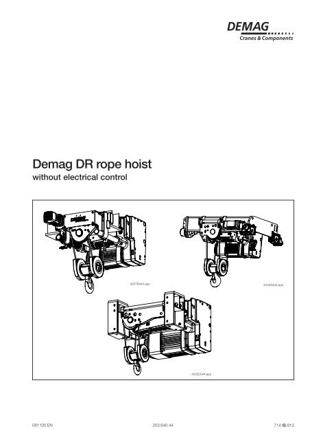
<strong>Demag</strong> <strong>DR</strong> <strong>rope</strong> <strong>hoist</strong><br />
without electrical control<br />
42576444.eps<br />
42352044.eps<br />
42349444.eps<br />
081105 EN 203 640 44 714 IS 813
Manufacturer <strong>Demag</strong> <strong>Cranes</strong> & <strong>Components</strong> GmbH<br />
P.O. Box 67, D-58286 Wetter<br />
Telephone (+49 2335) 92-0 · Telefax (+49 2335) 927676<br />
www.demagcranes.com<br />
Further<br />
documents<br />
Operating<br />
instructions<br />
Please fill in the following table before first putting the <strong>hoist</strong> into service.<br />
This provides you with a definitive documentation of your <strong>Demag</strong> <strong>rope</strong> <strong>hoist</strong><br />
and important information if you ever have to contact the manufacturer or his<br />
representative.<br />
Owner<br />
Where in use<br />
Range<br />
Serial number<br />
Main <strong>hoist</strong> motor number<br />
Operating voltage<br />
Control voltage<br />
Frequency<br />
Wiring diagram number<br />
<strong>Demag</strong> <strong>rope</strong><br />
<strong>hoist</strong><br />
F<strong>DR</strong><br />
3 - F<strong>DR</strong><br />
5-<br />
F<strong>DR</strong><br />
10<br />
( PRO)<br />
214 932<br />
44<br />
720 IS 813<br />
<strong>Demag</strong> <strong>rope</strong><br />
<strong>hoist</strong><br />
EK<strong>DR</strong><br />
3 - EK<strong>DR</strong><br />
5-<br />
EK<strong>DR</strong><br />
10<br />
( PRO)<br />
214 725<br />
44<br />
720 IS 813<br />
<strong>Demag</strong> <strong>rope</strong><br />
<strong>hoist</strong><br />
EZ<strong>DR</strong><br />
5-<br />
EZ<strong>DR</strong><br />
10<br />
( PRO)<br />
214 961<br />
44<br />
720 IS 813<br />
<strong>Demag</strong> <strong>rope</strong><br />
<strong>hoist</strong><br />
F<strong>DR</strong><br />
3 - F<strong>DR</strong><br />
5-<br />
F<strong>DR</strong><br />
10<br />
( COM)<br />
214 990<br />
44<br />
720 IS 813<br />
<strong>Demag</strong> <strong>rope</strong><br />
<strong>hoist</strong><br />
EK<strong>DR</strong><br />
3 - EK<strong>DR</strong><br />
5-<br />
EK<strong>DR</strong><br />
10<br />
( COM<br />
214 916<br />
44<br />
720 IS 813<br />
<strong>Demag</strong> <strong>rope</strong><br />
<strong>hoist</strong><br />
EZ<strong>DR</strong><br />
5-<br />
EZ<strong>DR</strong><br />
10<br />
( COM)<br />
214 965<br />
44<br />
720 IS 813<br />
Dedrive Compact<br />
DIC<br />
214 708<br />
44<br />
720 IS 922<br />
CD Dedrive<br />
Compact<br />
DIC<br />
213 137<br />
44<br />
716 IS 922<br />
External pulse<br />
generator<br />
214 372<br />
44<br />
720 IS 919<br />
Z motor<br />
range<br />
214 228<br />
44<br />
720 IS 919<br />
2 20364044.p65/081105
20364044.p65/081105<br />
Introduction<br />
This document contains information on <strong>rope</strong> <strong>hoist</strong>s without electrical control. It applies<br />
for <strong>DR</strong>-Pro, EK<strong>DR</strong>-Pro, EZ<strong>DR</strong>-Pro, F<strong>DR</strong>-Pro, EK<strong>DR</strong>-Com, EZ<strong>DR</strong>-Com, F<strong>DR</strong>-<br />
Com <strong>rope</strong> <strong>hoist</strong>s.<br />
Depending on the type, the standard scope of delivery includes:<br />
- 12/2-pole <strong>hoist</strong> motor with Microtherm and EG integrated pulse generator<br />
- GS and VE brake modules<br />
- 4-pole <strong>hoist</strong> motor with Microtherm and mechanical mounting device for AG 1 - 3<br />
external pulse generators<br />
- GS and VE brake modules<br />
- 4-pole cross travel motor with Microtherm<br />
- GE and VE brake modules<br />
- Base plate in the <strong>rope</strong> <strong>hoist</strong> electrical enclosure for connecting the <strong>hoist</strong> motor and<br />
sensors<br />
- SGG geared limit switch<br />
- SGS overload cut-out<br />
3
Design overview<br />
Example of EK<strong>DR</strong><br />
Fig. 1<br />
Thrust rocker<br />
Electrical equipment cover<br />
with terminal strip and<br />
geared limit switch<br />
4/1 bottom block<br />
Explanation of size designation / type assignment<br />
EK <strong>DR</strong> - Pro 3 - 3,2 4/1 - 6 Z - 6/1 - 400 - 00 - 50 - 30 300 45<br />
Travel motor<br />
EK<strong>DR</strong> low-headroom monorail <strong>hoist</strong><br />
Gearbox with <strong>hoist</strong> motor<br />
42577844.eps<br />
Rail head width in mm<br />
} Only for EZ<strong>DR</strong><br />
or track gauge in mm<br />
Flange width of the girder in mm<br />
or girder section and size (IPE240)<br />
Maximum cross-travel speed in m/min<br />
Frequency [Hz]<br />
Electrical equipment code 1)<br />
Operating voltage [ V ]<br />
Hoist speed in m/min<br />
Motor type: Z = Cylindrical rotor<br />
Hook path in m<br />
20364044.p65/081105<br />
E = Electric travel trolley<br />
1) Code 00 <strong>DR</strong> without electrical control<br />
Code 01 EK<strong>DR</strong> with internal electrics for application on a crane. Crane bridge enclosure, DSE-8R control pendant with control cable and cables for the<br />
mobile floor control must be ordered separately.<br />
Code 02 F<strong>DR</strong>/EK<strong>DR</strong>/EZ<strong>DR</strong> with internal electrics and solo electrics with crane switch and transformer fitted in an enclosure on the trolley, for application as a<br />
solo trolley. DSE-8R control pendant with control cable must be ordered separately.<br />
Code 03 Like code 01 but control via radio control system<br />
Code 04 Like code 02 but control via radio control system<br />
4 Code 05 EK<strong>DR</strong> with fitted parallel interface “in”<br />
Reeving<br />
SWL in t<br />
Range 3; 5; 10<br />
<strong>Demag</strong> <strong>rope</strong> <strong>hoist</strong><br />
K = Low-headroom monorail <strong>hoist</strong><br />
Z = Crab<br />
F = Stationary
20364044.p65/081105<br />
Selection criteria<br />
<strong>DR</strong>-Pro F-/EK<strong>DR</strong> 3 - F-/EK-/EZ<strong>DR</strong> 5, 10<br />
The size of the <strong>hoist</strong> is determined by the load<br />
spectrum, average operating time per working day,<br />
SWL and reeving.<br />
The load spectrum<br />
(in most cases estimated) can be evaluated in<br />
accordance with the following definitions:<br />
1 Light<br />
Hoist units which are usually subject to very small<br />
loads and in exceptional cases only to maximum<br />
loads.<br />
SWL<br />
Operating time<br />
2 Medium<br />
Hoist units which are usually subject to small loads<br />
but rather often to maximum loads.<br />
SWL<br />
SWL<br />
SWL<br />
Operating time<br />
Operating time<br />
Operating time<br />
Small partial load<br />
Small dead load<br />
Heavy partial load<br />
Medium partial load<br />
Medium dead load<br />
3 Heavy<br />
Hoist units which are usually subject to medium<br />
loads but frequently to maximum loads.<br />
Heavy dead load<br />
4 Very heavy<br />
Hoist units which are usually subject to maximum or<br />
almost maximum loads.<br />
Selection table<br />
Very heavy dead load<br />
Range Group<br />
of<br />
mechanisms<br />
to<br />
FEM/<br />
ISO<br />
F-/<br />
EK-<br />
<strong>DR</strong><br />
3<br />
F-/<br />
EK-/<br />
EZ-<br />
<strong>DR</strong><br />
5<br />
F-/<br />
EK-/<br />
EZ-<br />
<strong>DR</strong><br />
10<br />
1. What are the operating conditions?<br />
2. What is the specified safe working load?<br />
3. To what height must the load be lifted?<br />
4. What is the required lifting speed?<br />
The<br />
g<br />
roup<br />
is<br />
Group<br />
of<br />
mechanisms<br />
F EM/<br />
ISO<br />
1)<br />
determined<br />
from<br />
the<br />
operating<br />
time<br />
and<br />
load<br />
spectrum<br />
Rope reeving<br />
2 / 1,<br />
4/<br />
2<br />
5. Do the loads need to be lifted and lowered with<br />
high precision?<br />
6. Is horizontal load travel necessary?<br />
7. How is the <strong>hoist</strong> to be controlled?<br />
Load spectrum<br />
Average<br />
operating<br />
time<br />
per<br />
day<br />
in<br />
hours<br />
1 Light 4-8 8-16 over<br />
16<br />
2 Medium 2-4 4-8 8-16<br />
3 Heavy 1-2 2-4 4-8<br />
4 Very heavy<br />
0, 5-1<br />
1-2 2-4<br />
Group<br />
of<br />
mechanisms<br />
to<br />
FEM 2 m<br />
3 m<br />
4 m<br />
ISO M 5<br />
M 6<br />
M 7<br />
2m/ M 5 3m/ M 6 4m/ M 7 2m/ M 5 3m/ M 6 4m/ M 7 2m/ M 5 3m/ M7<br />
4 m/<br />
M 7<br />
2 )<br />
/ 1<br />
4 6 / 1<br />
Range SWL in<br />
t<br />
<strong>DR</strong> 5<br />
2, 5 2 1, 6 5 4 3, 2 - - -<br />
<strong>DR</strong> 10<br />
5 4 3, 2 10 8 6, 3 16 12, 5 -<br />
Example<br />
SWL 5 t<br />
Load spectrum “medium” from table<br />
Hoist speed 6 m/min<br />
Creep <strong>hoist</strong> speed 1 m/min<br />
Reeving 4/1<br />
Average hook path 3 m<br />
No. of cycles/hour 20<br />
Working time/day 8 hours<br />
The average operating time per working day is estimated or calculated as follows:<br />
2 x average hook path x no.<br />
of<br />
cycles/h x working<br />
time/day<br />
Operating time/day =<br />
60 x lifting speed<br />
Operating time/day<br />
2 x 3 x 20 x 8<br />
=<br />
= 2,66<br />
60 x 6<br />
For the “medium” load spectrum and an average daily operating time of 2,66 hours,<br />
the table shows group 2 m. For a load capacity of 5 t and 4/1 <strong>rope</strong> reeving, the table<br />
indicates <strong>hoist</strong> size <strong>DR</strong> 5 - 5.<br />
SWL Hook path<br />
Lifting speed<br />
m/ min<br />
SWL Hook path<br />
Lifting speed<br />
m/<br />
min<br />
t m V1 V2 V3 t m V1 V2 V3<br />
2/ 1<br />
4/<br />
1<br />
2 m/<br />
M 5 1,<br />
6<br />
3,<br />
2<br />
3 m/<br />
M 6 1, 25<br />
12; 20<br />
12/ 2 1 8/<br />
3 2-25<br />
3)<br />
2,<br />
5<br />
4 m/<br />
M 7<br />
1 2<br />
1) Gearbox service life 20 % above the FEM value<br />
2) 4/2 and 6/1 <strong>rope</strong> reeving only for <strong>DR</strong> 10<br />
hours<br />
2 )<br />
6; 10<br />
6/ 1 9 / 1,<br />
5 1-12,<br />
5 3)<br />
2 m/<br />
M 5 2,<br />
5<br />
5<br />
3 m/<br />
M 6 2 12; 20<br />
12/ 2 1 8/<br />
3 2-25<br />
3)<br />
4 6; 10<br />
6/ 1 9 / 1,<br />
5 1-12,<br />
5 3)<br />
4 m/<br />
M 7 1, 6<br />
3,<br />
2<br />
2 m/<br />
M 5 5<br />
10<br />
3 m/<br />
M 6 4 12; 20<br />
1 0/<br />
1,<br />
7 2 -18<br />
3)<br />
2-25<br />
3)<br />
8 6; 10<br />
5 / 0,<br />
8 1 -9<br />
3)<br />
1-12,<br />
5 3)<br />
4 m/<br />
M 7 3, 2<br />
6,<br />
3<br />
4 / 2<br />
6/<br />
1 4)<br />
2 m/<br />
M 5 5<br />
16<br />
3 m/<br />
M 6 4<br />
5,<br />
8;<br />
11,<br />
35;<br />
15,<br />
2<br />
1 0/<br />
1,<br />
7 2 -18<br />
3)<br />
2-25<br />
3)<br />
12,<br />
5 6, 7;<br />
13,<br />
3 2, 7/<br />
0,<br />
4 0, 7-6<br />
-<br />
4 m/<br />
M 7 3, 2<br />
10<br />
3) for 87 Hz delta operation<br />
4) 6/1 <strong>rope</strong> reeving only for EZ<strong>DR</strong> 10<br />
5
<strong>DR</strong>-Com F-/EK<strong>DR</strong> 3 - F-/EK-/EZ<strong>DR</strong> 5, 10<br />
The size of the <strong>hoist</strong> is determined by the load<br />
spectrum, average operating time per working day,<br />
SWL and reeving.<br />
The load spectrum<br />
(in most cases estimated) can be evaluated in<br />
accordance with the following definitions:<br />
1 Light<br />
Hoist units which are usually subject to very small<br />
loads and in exceptional cases only to maximum<br />
loads.<br />
SWL<br />
Operating time<br />
2 Medium<br />
Hoist units which are usually subject to small loads<br />
but rather often to maximum loads.<br />
SWL<br />
SWL<br />
SWL<br />
Operating time<br />
Operating time<br />
Operating time<br />
Small partial load<br />
Small dead load<br />
Heavy partial load<br />
Medium partial load<br />
Medium dead load<br />
3 Heavy<br />
Hoist units which are usually subject to medium<br />
loads but frequently to maximum loads.<br />
Heavy dead load<br />
4 Very heavy<br />
Hoist units which are usually subject to maximum or<br />
almost maximum loads.<br />
Selection table<br />
Very heavy dead load<br />
1. What are the operating conditions?<br />
2. What is the specified safe working load?<br />
3. To what height must the load be lifted?<br />
4. What is the required lifting speed?<br />
The<br />
Load<br />
g<br />
roup<br />
is<br />
spectrum<br />
determined<br />
from<br />
the<br />
operating<br />
time<br />
and<br />
load<br />
spectrum<br />
5. Do the loads need to be lifted and lowered with<br />
high precision?<br />
6. Is horizontal load travel necessary?<br />
7. How is the <strong>hoist</strong> to be controlled?<br />
G roup<br />
of<br />
mechanisms<br />
to<br />
FEM/<br />
ISO<br />
1) 1 Am/<br />
M 4<br />
Rope reeving<br />
arrangement<br />
4/<br />
1<br />
Range SWL<br />
in<br />
t<br />
<strong>DR</strong> 3<br />
3,<br />
2<br />
<strong>DR</strong> 5<br />
5<br />
<strong>DR</strong> 10<br />
10<br />
Average<br />
operating<br />
time<br />
per<br />
day<br />
in<br />
hours<br />
1 Light 2-4<br />
2 Medium 1-2<br />
3 Heavy 0,<br />
5-1<br />
4 Very heavy<br />
up<br />
to<br />
0,<br />
5<br />
Group<br />
of<br />
mechanisms<br />
to<br />
FEM 1 Am<br />
ISO M 4<br />
Example<br />
SWL 5 t<br />
Load spectrum “medium” from table<br />
Hoist speed 4.5 m/min<br />
Creep <strong>hoist</strong> speed 0,8 m/min<br />
Reeving 4/1<br />
Average hook path 3 m<br />
No. of cycles/hour 10<br />
Working time/day 8 hours<br />
The average operating time per working day is estimated or calculated as follows:<br />
Operating time/day<br />
Operating time/day<br />
For the “medium” load spectrum and an average daily operating time of 1,7 hours,<br />
the table shows group 1 Am . For a load capacity of 5 t and 4/1 <strong>rope</strong> reeving, the<br />
table indicates <strong>hoist</strong> size <strong>DR</strong> 5 - 5.<br />
Range Group<br />
of<br />
mechanisms<br />
to<br />
FEM/<br />
ISO<br />
F-/<br />
EK<strong>DR</strong><br />
3<br />
F-/<br />
EK-/<br />
EZ<strong>DR</strong><br />
5<br />
=<br />
2 x average hook path x no.<br />
of<br />
cycles/h x working<br />
time/day<br />
60 x lifting speed<br />
2 x 3 x 10 x 8<br />
=<br />
=<br />
60 x 4,5<br />
SWL Hook path<br />
Lifting<br />
speed<br />
m/<br />
min<br />
t m<br />
4/<br />
1<br />
V1<br />
6,<br />
3<br />
F-/<br />
EK-/<br />
EZ<strong>DR</strong><br />
10<br />
8<br />
6; 10<br />
4/<br />
0,<br />
7<br />
10<br />
6 1) Gearbox service life 20 % above the FEM value<br />
20364044.p65/081105<br />
1 Am/<br />
M<br />
4<br />
1,<br />
7<br />
hours<br />
2<br />
2,<br />
5<br />
3,<br />
2<br />
4<br />
5<br />
6; 10<br />
4,<br />
5/<br />
0,<br />
8<br />
6; 10<br />
4,<br />
5/<br />
0,<br />
8
20364044.p65/081105<br />
7
Key data pole-changing <strong>hoist</strong> drives <strong>DR</strong> 3 – <strong>DR</strong> 5 – <strong>DR</strong> 10<br />
Design is in accordance with the VDE regulations and the design rules of the FEM, to meet the high demands made on<br />
electric <strong>hoist</strong>s.<br />
Main/creep lifting F6<br />
Range <strong>DR</strong><br />
3 No.<br />
of<br />
poles<br />
Required supply cable conductor cross sections and fuse links<br />
Code P % CDF<br />
n Starts/ h Rated current<br />
INand<br />
starting<br />
current<br />
IA<br />
for<br />
50<br />
Hz<br />
cos cos<br />
400 V<br />
ϕN ϕA Motor size<br />
kWrpm IN ( A)<br />
IA ( A)<br />
ZBR<br />
100<br />
C 12/<br />
2 - B050<br />
ZBR<br />
100<br />
D 12/<br />
2 - B050<br />
12<br />
0, 55<br />
20 430 240 4, 6<br />
7 0, 53<br />
0,<br />
72<br />
V1<br />
2 3, 4 40 2800 120 8, 5<br />
40 0, 78<br />
0,<br />
88<br />
12<br />
0, 8 20 410 240 5, 7<br />
9 0, 55<br />
0,<br />
75<br />
V2<br />
2 5, 3 40 2780 120 11 55 0, 88<br />
0,<br />
85<br />
Range<br />
<strong>DR</strong><br />
3<br />
Mains connection<br />
delay<br />
fuse<br />
for<br />
50<br />
Hz<br />
1)<br />
Supply lines<br />
for<br />
5%<br />
voltage<br />
drop<br />
∆U and<br />
starting<br />
current<br />
IA<br />
for<br />
50<br />
Hz<br />
2)<br />
4 00<br />
V<br />
400 V ( ∆ U 20<br />
V)<br />
Motor size<br />
A mm² m<br />
ZBR 100<br />
C 12/<br />
2<br />
201, 5<br />
25<br />
ZBR 100<br />
D 12/<br />
2<br />
251, 5<br />
19<br />
Range <strong>DR</strong><br />
5 No.<br />
of<br />
poles<br />
Code P % CDF<br />
n Starts/ h Rated current<br />
INand<br />
starting<br />
current<br />
IA<br />
for<br />
50<br />
Hz<br />
cos cos<br />
400 V<br />
ϕN ϕA Motor size<br />
kWrpm IN ( A)<br />
IA ( A)<br />
ZBR<br />
100<br />
D 12/<br />
2 - B050<br />
ZBR<br />
132<br />
D 12/<br />
2 - B140<br />
12<br />
0, 8 20 410 240 5, 7<br />
9 0, 55<br />
0,<br />
75<br />
V1<br />
2 5, 3 40 2780 120 11 55 0, 88<br />
0,<br />
85<br />
12<br />
1, 4 20 400 240 9, 6<br />
15 0, 54<br />
0,<br />
68<br />
V2<br />
2 8, 9 40 2870 120 18 120 0, 89<br />
0,<br />
85<br />
Range<br />
<strong>DR</strong><br />
5<br />
Mains connection<br />
delay<br />
fuse<br />
for<br />
50<br />
Hz<br />
1)<br />
Supply lines<br />
for<br />
5%<br />
voltage<br />
drop<br />
∆U and<br />
starting<br />
current<br />
IA<br />
for<br />
50<br />
Hz<br />
2)<br />
4 00<br />
V<br />
400 V ( ∆ U 20<br />
V)<br />
Motor size<br />
A mm² m<br />
ZBR 100<br />
D 12/<br />
2<br />
251, 5<br />
19<br />
ZBR 132<br />
D 12/<br />
2<br />
502, 5<br />
15<br />
Range <strong>DR</strong><br />
10<br />
No.<br />
of<br />
poles<br />
Code P % CDF<br />
n Starts/ h Rated current<br />
INand<br />
starting<br />
current<br />
IA<br />
for<br />
50<br />
Hz<br />
cos cos<br />
400 V<br />
ϕN ϕA Motor size<br />
kWrpm IN ( A)<br />
IA ( A)<br />
ZBR<br />
132<br />
D 12/<br />
2 - B140<br />
12<br />
1, 4 20 400 240 9, 6<br />
15 0, 54<br />
0,<br />
68<br />
V1<br />
2 8, 9 40 2870 120 18 120 0, 89<br />
0,<br />
85<br />
Range<br />
<strong>DR</strong><br />
10<br />
Mains connection<br />
delay<br />
fuse<br />
for<br />
50<br />
Hz<br />
1)<br />
Supply lines<br />
for<br />
5%<br />
voltage<br />
drop<br />
∆U and<br />
starting<br />
current<br />
IA<br />
for<br />
50<br />
Hz<br />
2)<br />
4 00<br />
V<br />
400 V ( ∆ U 20<br />
V)<br />
Motor size<br />
A mm² m<br />
ZBR 132<br />
D 12/<br />
2<br />
502, 5<br />
15<br />
1) Fuse links also apply in conjunction with a cross travel motor.<br />
8 2) The lengths of the supply lines are calculated on the basis of an earth-loop impedance of 200 mΩ.<br />
20364044.p65/081105
20364044.p65/081105<br />
Key data cross travel drives <strong>DR</strong> 3 – <strong>DR</strong> 5 – <strong>DR</strong> 10<br />
The cross travel drives of the <strong>DR</strong> without electrical control are designed for operation with a <strong>Demag</strong> frequency inverter in the<br />
120 Hz range. We recommend that <strong>Demag</strong> DIC Dedrive Compact frequency inverters be used. Owing to the large input voltage<br />
range of the Dedrive Compact, the <strong>DR</strong> without electrical control can be operated with mains voltages of 380...480 V with<br />
50...60 Hz. At 380 V, the max. frequency must be reduced by 5 Hz.<br />
Key data of inverter-controlled cross travel drive <strong>DR</strong> 3, <strong>DR</strong> 5, <strong>DR</strong> 10 - 2/1 - 4/1 - 4/2<br />
Range <strong>DR</strong><br />
3-10<br />
No. of<br />
poles<br />
% CDF<br />
Output<br />
Current<br />
cos ϕ n<br />
Recommended<br />
P<br />
at<br />
220<br />
V<br />
for<br />
50<br />
Hz<br />
inverter<br />
type<br />
Motor size<br />
k W<br />
I ( A)<br />
rpm Dedrive<br />
Compact<br />
ZBA 71<br />
B4<br />
- B003<br />
4 60 0, 37<br />
2, 6<br />
0, 54<br />
1375 DIC-4-004-E<br />
Key data of inverter-controlled cross travel drive EZ<strong>DR</strong> 10 -Pro 6/1<br />
Range <strong>DR</strong><br />
10<br />
No. of<br />
poles<br />
% CDF<br />
Output<br />
Current<br />
cos ϕ n<br />
Recommended<br />
P<br />
at<br />
220<br />
V<br />
for<br />
50<br />
Hz<br />
inverter<br />
type<br />
Motor size<br />
k W<br />
I ( A)<br />
rpm Dedrive<br />
Compact<br />
ZBA 90<br />
A4<br />
- B007<br />
4 60 1, 1<br />
5, 1<br />
0, 74<br />
1400 DIC-4-007-E<br />
Example for calculating the cross sections<br />
of the conductors of cables exceeding<br />
the length indicated in the table:<br />
ZBR 100 C 2/12, 400 V required length 25 m<br />
Known cross section x requiredlength<br />
2,5 x 25<br />
=<br />
= 4<br />
Known cable length<br />
16<br />
2<br />
mm<br />
9
Key data of inverter-operated <strong>hoist</strong> drives <strong>DR</strong> 3, <strong>DR</strong> 5, <strong>DR</strong> 10<br />
Design is in accordance with the VDE regulations and the design rules of the FEM, to meet the high demands made on<br />
electric <strong>hoist</strong>s.<br />
The <strong>hoist</strong> drives of the <strong>DR</strong> without electrical control are designed for operation with a <strong>Demag</strong> frequency inverter in the 87 Hz<br />
range. We recommend that <strong>Demag</strong> DIC Dedrive Compact frequency inverters be used. Owing to the large input voltage range of<br />
the Dedrive Compact, the <strong>DR</strong> without electrical control can be operated with mains voltages of 380...480 V with 50...60 Hz. At<br />
380 V, the max. frequency must be reduced by 5 Hz.<br />
Range <strong>DR</strong><br />
3<br />
No. of<br />
poles<br />
Code FEM classification<br />
% CDF<br />
Output<br />
P<br />
Current<br />
at<br />
220<br />
V<br />
cos ϕ n<br />
for<br />
50<br />
Hz<br />
Recommended<br />
inverter<br />
type<br />
Motor size<br />
k W I ( A)<br />
rpm Dedrive<br />
Compact<br />
ZBR<br />
100<br />
B 4 - B050<br />
2m<br />
DIC-4-017<br />
ZBR 100<br />
B 4 - B050<br />
4 V3<br />
3m 604, 2 16, 9 0, 85<br />
1350<br />
DIC-4-014<br />
ZBR 100<br />
B 4 - B050<br />
4m DIC-4-014<br />
Range D R 3<br />
Mains connection<br />
delay<br />
fuse<br />
for<br />
50<br />
Hz<br />
1)<br />
Supply lines<br />
for<br />
5%<br />
voltage<br />
drop<br />
∆U ) 2<br />
4 00<br />
V<br />
400 V ( ∆ U 20<br />
V)<br />
Inverter type<br />
A mm² m<br />
DIC-4-017 161, 5<br />
58<br />
DIC-4-014 161, 5<br />
70<br />
Range <strong>DR</strong><br />
5<br />
No. of<br />
poles<br />
Code FEM classification<br />
% CDF<br />
Output<br />
P<br />
Current<br />
at<br />
220<br />
V<br />
cos ϕ n<br />
for<br />
50<br />
Hz<br />
Range D R 10<br />
Mains connection<br />
delay<br />
fuse<br />
for<br />
50<br />
Hz<br />
1)<br />
Supply lines<br />
for<br />
5%<br />
voltage<br />
drop<br />
∆U ) 2<br />
4 00<br />
V<br />
400 V ( ∆ U 20<br />
V)<br />
Inverter type<br />
A mm² m<br />
Recommended<br />
inverter<br />
type<br />
Motor size<br />
k W I ( A)<br />
rpm Dedrive<br />
Compact<br />
ZBR<br />
132<br />
B 4 - B140<br />
2m<br />
8, 3 29, 0 0, 87<br />
1420 DIC-4-025<br />
ZBR 112<br />
A 4 - B140<br />
4 V3<br />
3m<br />
60<br />
DIC-4-025<br />
5, 3 18, 7 0, 84<br />
1430<br />
ZBR 112<br />
A 4 - B140<br />
4m DIC-4-017<br />
Range D R 5<br />
Mains connection<br />
delay<br />
fuse<br />
for<br />
50<br />
Hz<br />
1)<br />
Supply lines<br />
for<br />
5%<br />
voltage<br />
drop<br />
∆U ) 2<br />
4 00<br />
V<br />
400 V ( ∆ U 20<br />
V)<br />
Inverter type<br />
A mm² m<br />
DIC-4-025 352, 5<br />
65<br />
DIC-4-017 161, 5<br />
58<br />
Range <strong>DR</strong><br />
10<br />
No. of<br />
poles<br />
Code FEM classification<br />
% CDF<br />
Output<br />
P<br />
Current<br />
at<br />
220<br />
V<br />
cos ϕ n<br />
for<br />
50<br />
Hz<br />
Recommended<br />
inverter<br />
type<br />
Motor size<br />
k W I ( A)<br />
rpm Dedrive<br />
Compact<br />
ZBR<br />
132<br />
C 4 - B140<br />
2m<br />
10, 2 38, 0 0, 84<br />
1425 DIC-4-040<br />
ZBR 132<br />
B 4 - B140<br />
V2<br />
3m<br />
60<br />
DIC-4-032<br />
8, 3 29, 0 0, 87<br />
1420<br />
ZBR 132<br />
B 4 - B140<br />
4m DIC-4-025<br />
4<br />
ZBR<br />
132<br />
C 4 - B140<br />
2m50 13, 1 46, 5 0, 83<br />
1410 DIC-4-040<br />
ZBR 132<br />
C 4 - B140<br />
V3<br />
3m<br />
DIC-4-040<br />
6010, 2 38, 0 0, 84<br />
1425<br />
ZBR 132<br />
C 4 - B140<br />
4m DIC-4-032<br />
20364044.p65/081105<br />
DIC-4-040 506, 0<br />
97<br />
DIC-4-032 354, 0<br />
80<br />
DIC-4-025 352, 5<br />
65<br />
1) Fuse links also apply in conjunction with a cross travel motor.<br />
10 2) The lengths of the supply lines are calculated on the basis of an earth-loop impedance of 200 mΩ.
20364044.p65/081105<br />
Parameter settings for recommended <strong>Demag</strong> DIC Dedrive Compact frequency inverter<br />
Please refer to the table below for the required parameter settings.<br />
For the <strong>hoist</strong> drives, rotary encoder feedback on the motor is required. We recommend that the <strong>Demag</strong> AG 2 external pulse generator<br />
be used together with the EM-ENC-02 extension module for the <strong>Demag</strong> Dedrive Compact frequency inverter.<br />
After entry of the rated motor values, it is absolutely necessary to perform parameter identification.<br />
No. Name Unit ZBA ZBR<br />
71B4 90A4 100 B4<br />
112 A4<br />
132 B4<br />
132<br />
C4<br />
6 0%<br />
5 0%<br />
60%<br />
030 Configuration - 410 210<br />
370 Rated voltage<br />
V 220<br />
371 Rated current<br />
A 2, 6<br />
5, 1 16, 9 18, 7 29, 0 46, 5 38,<br />
0<br />
372 Rated speed<br />
rpm 1375 1400 1350 1430 1420 1410 1425<br />
373 No. of<br />
pole<br />
pairs<br />
- 2<br />
374 Rated cosine<br />
phi<br />
- 0, 54<br />
0, 74<br />
0, 85<br />
0, 84<br />
0, 87<br />
0, 83<br />
0,<br />
84<br />
375 Rated frequency<br />
Hz 50<br />
376 Mech. rated<br />
output<br />
kW 0, 4<br />
1, 1 4, 2<br />
5, 3<br />
8, 3 13, 1 10,<br />
2<br />
417 Frequency switch-off<br />
limit<br />
Hz 250 100<br />
418 Min. frequency<br />
Hz 5 8<br />
419 M ax.<br />
frequency<br />
1) Hz120 84 85 86<br />
420 Acceleration Hz/ s<br />
25 42 42, 5<br />
43<br />
421 Deceleration Hz/ s<br />
50 42 42, 5<br />
43<br />
490 Operating mode<br />
encoder<br />
1<br />
- 0 4<br />
491<br />
Pulse<br />
number<br />
per<br />
revolution<br />
of<br />
encoder<br />
1<br />
- - Depending<br />
on<br />
rotary<br />
encoder<br />
used<br />
721 Amplification speed<br />
controller<br />
- 3 10<br />
722<br />
Integral<br />
action<br />
controller<br />
time<br />
speed<br />
ms200 100<br />
For further details regarding commissioning, the many control possibilities, the various <strong>hoist</strong> functions and the selection of further<br />
additional components of the DIC Dedrive Compact, refer to the operating instructions 214 708 44 and 214 716 44. The permissible<br />
ambient conditions must be complied with.<br />
1) At 380 V, the max. frequency must be reduced by 5 Hz.<br />
11
Connection plate with terminal strip for <strong>DR</strong> with 2-/12-pole <strong>hoist</strong><br />
Fig. 2<br />
1<br />
Top-hat rail, 200 mm long<br />
5<br />
PE<br />
J<br />
EG<br />
PE<br />
123456<br />
3 4<br />
42354944.eps<br />
12 20364044.p65/081105<br />
2-pole 2 pol. <strong>hoist</strong> HUB<br />
2<br />
PE PE<br />
PE<br />
12VE A 1A B 1B GDNE<br />
12-pole 12 pol. HUB <strong>hoist</strong><br />
K<br />
9<br />
6 7 8<br />
11 12<br />
10<br />
X52<br />
L<br />
Cross1<br />
Kreuz1 Cross2 Kreuz2<br />
2 3 PE 1 2 3 PE<br />
SGS SGG<br />
U V W<br />
U V W<br />
1<br />
8<br />
7<br />
6<br />
5<br />
4<br />
3<br />
2<br />
1<br />
PE<br />
2<br />
1<br />
ThH ThH Brg Brg BrH BrH SGS SGS PE SGG1SGG2 SGG3SGG4<br />
SGG5SGG6SGG7SGG8<br />
X161 X162 X163 PE X418 X482 X483 PE<br />
X11<br />
X48<br />
X16<br />
X5<br />
X53<br />
A<br />
PE<br />
PE<br />
X9<br />
B C D E F G H I
20364044.p65/081105<br />
Customer connections<br />
1 Top-hat rail<br />
2 12-pole <strong>hoist</strong> motor connection<br />
3 2-pole <strong>hoist</strong> motor connection<br />
4 EG integrated pulse generator<br />
5 Protective earth conductor PE<br />
6 Thermo-switch <strong>hoist</strong> motor<br />
7 Brake release contact <strong>hoist</strong> motor<br />
8 Brake <strong>hoist</strong> motor<br />
9 SGS overload protective device, electro-mechanical<br />
10 SGG geared limit switch<br />
11 Cross travel cut-out system, general<br />
12 Cross travel cut-out system, preliminary (v2 → v1)<br />
All terminals must be connected with up to 4 mm² Cu cross section, except<br />
2-pole <strong>hoist</strong> and PE which must be connected with up to 16 mm² Cu cross<br />
section.<br />
Factory connections<br />
A Terminal X11 (12-pole <strong>hoist</strong> motor)<br />
B Terminal X9 (2-pole <strong>hoist</strong> motor)<br />
C Terminal X10 (signals <strong>hoist</strong> motor)<br />
D Terminal X53 (SGS)<br />
E Protective earth conductor PE<br />
F Terminal X5 (SGG)<br />
G Terminal X16 (cut-out)<br />
H Terminal X48 (prel.)<br />
I Protective earth conductor PE<br />
J Protective earth conductor PE<br />
K Protective earth conductor PE<br />
L Connection X52 (integrated pulse generator <strong>hoist</strong> motor)<br />
13
Connection plate with terminal strip for <strong>DR</strong> with 4-pole <strong>hoist</strong> motor<br />
Fig. 3<br />
1<br />
Top-hat rail, 200 mm long<br />
5<br />
PE<br />
J<br />
EG<br />
PE<br />
123456<br />
3 4<br />
42356144.eps<br />
14 20364044.p65/081105<br />
2-pole 2 pol. HUB <strong>hoist</strong><br />
2<br />
PE PE<br />
PE<br />
12VE A 1A B 1B GDNE<br />
12-pole 12 pol. HUB <strong>hoist</strong><br />
K<br />
9<br />
6 7 8<br />
11 12<br />
10<br />
X52<br />
L<br />
Kreuz1 Cross1<br />
Cross2<br />
Kreuz2<br />
SGS SGG<br />
U V W<br />
U V W<br />
PE<br />
3<br />
2<br />
1<br />
PE<br />
3<br />
2<br />
1<br />
8<br />
7<br />
6<br />
5<br />
4<br />
3<br />
2<br />
1<br />
PE<br />
2<br />
1<br />
ThH ThH Brg Brg BrH BrH SGS SGS PE SGG1SGG2 SGG3SGG4<br />
SGG5SGG6SGG7SGG8<br />
X161 X162 X163 PE X418 X482 X483 PE<br />
X11<br />
X48<br />
X16<br />
X5<br />
X53<br />
A<br />
PE<br />
PE<br />
X9<br />
B C D E F G H I
20364044.p65/081105<br />
Customer connections<br />
For the <strong>DR</strong> with 4-pole <strong>hoist</strong> motor, the connection is made directly in the motor<br />
terminal box<br />
1 Top-hat rail<br />
2 -<br />
3 -<br />
4 -<br />
5 Protective earth conductor PE<br />
6 -<br />
7 -<br />
8 -<br />
9 SGS overload protective device, electro-mechanical<br />
10 SGG geared limit switch<br />
11 Cross travel cut-out system, general<br />
12 Cross travel cut-out system, preliminary (v2 → v1)<br />
All terminals must be connected with up to 4 mm² Cu cross section, except<br />
2-pole <strong>hoist</strong> and PE which must be connected with up to 16 mm² Cu cross<br />
section.<br />
Factory connections<br />
A Terminal X11 (12-pole <strong>hoist</strong> motor)<br />
B Terminal X9 (2-pole <strong>hoist</strong> motor)<br />
C Terminal X10 (signals <strong>hoist</strong> motor)<br />
D Terminal X53 (SGS)<br />
E Protective earth conductor PE<br />
F Terminal X5 (SGG)<br />
G Terminal X16 (cut-out)<br />
H Terminal X48 (prel.)<br />
I Protective earth conductor PE<br />
J Protective earth conductor PE<br />
K Protective earth conductor PE<br />
L Connection X52 (integrated pulse generator <strong>hoist</strong> motor)<br />
15
Cable unions<br />
1<br />
1<br />
Fig. 4<br />
<strong>DR</strong> 3 cable unions <strong>DR</strong> 5 cable unions<br />
2<br />
<strong>DR</strong> 10 cable unions<br />
3<br />
3<br />
2<br />
42355044.eps<br />
42355244.eps<br />
1 Round cable union M25 1)<br />
2 Round cable union M20 1)<br />
1) Screw-type unions must have long threads (approx. 15 mm)<br />
e.g. cable union Schlemmer-Tec, manufacturer no. 5307620 (M20 x 1,5)<br />
16 cable union Schlemmer-Tec, manufacturer no. 5307125 (M25 x 1,5)<br />
20364044.p65/081105<br />
1<br />
Cable unions, <strong>DR</strong> 3, <strong>DR</strong> 5, <strong>DR</strong> 10 cover<br />
3 Twist-type cable entry gland for cable glands up to max. 12,5 mm<br />
4 Round cable union M25<br />
3<br />
2<br />
42355144.eps<br />
4<br />
42355344.eps
20364044.p65/081105<br />
Connection diagrams<br />
Hoist motor connection diagrams<br />
Pole-changing <strong>hoist</strong> drive<br />
low<br />
speed<br />
PE<br />
Fig. 5<br />
1L1 1L2 1L3<br />
1U<br />
2U<br />
PE<br />
U U U<br />
1V<br />
1W<br />
M<br />
3~<br />
U U<br />
2V 2W<br />
U<br />
CW<br />
1L1 1L2 1L3<br />
~ ~<br />
U V W<br />
high<br />
speed<br />
U1 V1W1<br />
M 3~<br />
U2<br />
V2<br />
W2<br />
CCW<br />
Switchgear<br />
cabinet<br />
Motor<br />
TB1<br />
TB2<br />
1S2<br />
1S1<br />
VE<br />
RD BU WH<br />
RD<br />
BD2 BD1<br />
Hoist drive with frequency inverter<br />
VE<br />
RD BU WH<br />
RD<br />
X1<br />
X1<br />
U<br />
Frequency<br />
inverter <strong>hoist</strong><br />
Thermo-switch<br />
Brake monitoring<br />
Switchgear<br />
cabinet<br />
2L1 2L2 2L3<br />
BD2 BD1<br />
Motor<br />
7<br />
6<br />
5<br />
4<br />
3<br />
2<br />
1 + -<br />
GS<br />
~<br />
~<br />
~<br />
2L1 2L2 2L3<br />
Re-start block min.<br />
250 ms!<br />
6<br />
5<br />
4<br />
3<br />
2<br />
1<br />
7<br />
GS<br />
TB1<br />
TB2<br />
1S2<br />
1S1<br />
42356044.eps<br />
~<br />
~<br />
~<br />
+ -<br />
Brake monitoring<br />
Thermo-switch PCB in <strong>DR</strong><br />
Re-start block min.<br />
250 ms!<br />
Motor<br />
terminal box<br />
42355944.eps<br />
Y/Y<br />
Y/D<br />
ZBR 100 motor terminal block<br />
1U<br />
T1<br />
1V<br />
T2<br />
U U U<br />
1SP1 1SP2 1SP3 2SP1 2SP2 2SP3<br />
U2<br />
U1<br />
1U<br />
T1<br />
1SP1<br />
1W<br />
T3<br />
1V<br />
T2<br />
1SP2<br />
2U<br />
T11<br />
1W<br />
T3<br />
1SP3<br />
2V 2W<br />
T12 T13<br />
U U U<br />
2U<br />
T11<br />
2SP1<br />
2V<br />
T12<br />
2SP2<br />
BD1 BD2<br />
2W<br />
T13<br />
2SP3<br />
BD1<br />
SP1<br />
1L1 1L2 1L3 1L1* 1L2* 1L3* L+ 1L-<br />
1U<br />
Motor terminal board<br />
V2<br />
V1<br />
W2<br />
W1<br />
W2 U2 V2<br />
U1 V1 W1<br />
1L1 1L2 1L3<br />
X1<br />
RD<br />
VE+ GS1 BD1<br />
VE<br />
- +<br />
WH BU RD<br />
4 3 X1<br />
GS<br />
BD1 BD2<br />
U<br />
SP1 SP2 TB1 TB2<br />
BD2<br />
SP2<br />
ZBR 132 motor terminal block<br />
1U<br />
T1<br />
1V<br />
T2<br />
U U U<br />
U U U<br />
1SP1 1SP2 1SP3 2SP1 2SP2 2SP3<br />
T1<br />
1SP1<br />
1L1 1L2 1L3 1L1* 1L2* 1L3* L+ 1L-<br />
TB1 TB2<br />
4 2 1<br />
wh gn bn<br />
1S3 1S2 1S1<br />
TB1 TB2 1S3 1S2 1S1<br />
SP1 SP2 TB1 TB2<br />
1W<br />
T3<br />
2U<br />
T11<br />
2W<br />
T13<br />
BD1 BD2<br />
1V<br />
T2<br />
1SP2<br />
1W<br />
T3<br />
1SP3<br />
2V<br />
T12<br />
2U<br />
T11<br />
2SP1<br />
2V<br />
T12<br />
2SP2<br />
2W<br />
T13<br />
2SP3<br />
BD1<br />
SP1<br />
U<br />
BD2<br />
SP2<br />
GS<br />
- +<br />
7 6 5 4 3 2 1<br />
WH BU<br />
2L3 2L2 2L1 BD2 X1<br />
VE<br />
4 2 1<br />
wh gn bn<br />
1S3 1S2 1S1<br />
TB1 TB2 1S3 1S2 1S1<br />
4 2 1<br />
wh gn bn<br />
1S3 1S2 1S1<br />
41003284.eps<br />
41004384.eps<br />
03800784.eps<br />
17
Cross travel motor connection diagram<br />
Cross-travel drive with frequency inverter<br />
Fig. 6<br />
PE<br />
1L1 1L2 1L3<br />
U1<br />
~ ~<br />
M 3~<br />
V1 W1<br />
TB1<br />
TB2<br />
EG integrated pulse<br />
generator<br />
Brake release contact<br />
Temperature sensor, <strong>hoist</strong><br />
and cross travel motor<br />
Thermo-switch<br />
Switchgear<br />
cabinet<br />
VE<br />
RD BU WH<br />
RD<br />
Motor<br />
X1<br />
BD2 BD1<br />
Brake<br />
2L1 2L2 2L3<br />
U<br />
6<br />
5<br />
4<br />
3<br />
2<br />
1<br />
7<br />
GE<br />
~<br />
~<br />
+ -<br />
Motor terminal<br />
block<br />
Motor terminal block<br />
18 20364044.p65/081105<br />
U1<br />
T1<br />
V1<br />
T2<br />
U1<br />
T1<br />
W1<br />
T3<br />
V1<br />
T2<br />
L1 L2 L3<br />
W1<br />
T3<br />
U<br />
SP1 SP2 TB1 TB2<br />
BD1<br />
SP1<br />
L+ L-<br />
BD1 BD2<br />
42355844.eps 41003384.eps<br />
BD2<br />
SP2<br />
TB1 TB2<br />
See operating instructions for Motors, type Z, ident. no. 214 228 44<br />
See operating instructions for Motors, type Z, ident. no. 214 228 44<br />
See operating instructions for Motors, type Z, ident. no. 214 228 44
20364044.p65/081105<br />
Brake control<br />
Various control modules are available for controlling <strong>Demag</strong> B003 to B680 disk<br />
brakes with DC magnets.<br />
All modules can also be fitted inside the switchgear cabinet.<br />
In this case, the brake coil must be protected against switching voltage peaks by<br />
means of a varistor, part no. 260 898 84, in the motor terminal box.<br />
All rectifiers feature varistor protection against overvoltage at the AC input and on the<br />
switching contact terminal as standard.<br />
The braking rectifiers are approved for a max. AC voltage of 500 V AC.<br />
Brake cut-out in the AC or DC circuit is possible with GE rectifiers (cross travel) and<br />
GS rectifiers (<strong>hoist</strong>) depending on the connection.<br />
Brake application times are highly dependent on the way in which the brake is<br />
switched off.<br />
For the <strong>DR</strong> without electrical control system, cut-out in the DC circuit by using the<br />
VE module is necessary.<br />
Operation with frequency inverters<br />
If ZB cylindrical rotor brake motors are operated together with inverters, the<br />
brake must be provided with a separate power supply and control.<br />
Brake control modules<br />
GE brake rectifiers (normal excitation)<br />
GE brake rectifiers are used for the cross travel drive of the <strong>DR</strong> as standard.<br />
They mainly consist of a half-wave rectifier with integrated free-wheeling circuit.<br />
GS brake rectifiers (high-speed excitation)<br />
GS brake rectifiers are used for the ZBR motors of the <strong>DR</strong> <strong>hoist</strong> drives as<br />
standard.<br />
The GS module includes a reversible rectifier which overexcites the brake for approx.<br />
0,3 seconds to release it and supplies it with the appropriate holding voltage<br />
from a half-wave rectifier (overexcitation factor of 2,5 with 3-phase connection).<br />
Important: When used with a pole-changing motor, GS modules must always<br />
be provided with a separate power supply.<br />
To ensure perfect functioning for cut-out of the GS and VE modules, i.e. switching<br />
with overexcitation, min. 250 ms must expire between cut-out and switching on<br />
again.<br />
VE voltage relays (voltage-dependent high-speed trip relay)<br />
VE voltage relays can be combined with GE, GS and GP brake rectifiers. VE<br />
voltage relays must only be used for brakes with a separate power supply.<br />
These modules are preferably used for inverter-fed motors. They are used for<br />
high-speed demagnetization of the brake to achieve fast brake application times<br />
without the need for additional wiring for brake cut-out in the DC circuit. VE<br />
voltage relays are connected to the brake power supply. The contact in the DC<br />
circuit is opened when the brake is switched off.<br />
19
SGG geared limit switch<br />
Fig. 7<br />
Adjusting instructions for SGG<br />
Operating principle<br />
Adjust<br />
Setting the contacts for individual<br />
adjustment:<br />
Setting the contacts for adjustment in<br />
blocks:<br />
Adjusting screw, black Adjusting screw, white<br />
For adjusting the geared limit switch, a hexagon socket key, 4 mm, is required.<br />
42589444.eps<br />
SGG/terminal strip connection<br />
SGG Switch contacts<br />
20 20364044.p65/081105<br />
1<br />
2<br />
3<br />
4<br />
1 1<br />
2 2<br />
3 3<br />
4 4<br />
5 5<br />
6 6<br />
7 7<br />
8 8<br />
Before setting the switching points, make sure that live contacts are provided with a<br />
touch guard in order to protect them against accidental contact.<br />
Allow for run-on!<br />
Each contact is allocated to a cam disk which is infinitely adjustable.<br />
The cam disks can be adjusted independently by means of the white adjusting<br />
screws.<br />
When turning the white adjusting screw clockwise, the cam disk is also turned clockwise.<br />
The switching point is shifted upwards in accordance with the hook path.<br />
When turning the screw anti-clockwise, the switching point is shifted downwards.<br />
Standard cam disks are designed in such a way that a max. useful path and a run-on<br />
path are available.<br />
The geared limit switch is already permanently connected with the control system via<br />
the system connector cable. For setting the contacts, turn the white adjusting screw<br />
until the contact maker opens the contact.<br />
If the run-on path is exceeded, the contact either opens or closes.<br />
The contacts are adjusted in blocks by means of the black adjusting screw. All cam<br />
disks are adjusted together, while the relative adjustment of the individual contacts<br />
remains unchanged. When turning the black adjusting screw clockwise, the cam<br />
disks are also turned clockwise.<br />
Approach cut-out points several times to check the limit switch functions are<br />
operating correctly!
20364044.p65/081105<br />
Technical data<br />
Transmission ratio:<br />
Switch contacts:<br />
Contact type:<br />
Cam disc:<br />
Switching point repeat accuracy:<br />
Electrical connection:<br />
Technical features:<br />
Compliance with standards<br />
Ambient temperature<br />
Type of enclosure<br />
Insulation class<br />
Approvals<br />
Technical features of<br />
switching elements:<br />
Positive opening to rated operating voltage<br />
Ui Thermal continuous current Ith Category acc. to VDE 0660:<br />
Mechanical service lives in switching<br />
cycles<br />
Terminal identification<br />
Approvals<br />
Current load to plug connector<br />
Outer dimensions:<br />
Length up to pinion cover<br />
Enclosure dimensions<br />
Overall height<br />
i = 205 with block setting of all cam disks designed for min. >1x10 6 switching<br />
operations<br />
4<br />
Change-over contact, snap-action contact, NC with automatic disconnection,<br />
contact material: silver/silver<br />
with 15° leading cams<br />
approx. +/-15 mm on hook, least favourable case for 2/1 reeving and hook path<br />
12 m. In this case, the 47 revolutions on the drive shaft result in an adjusting angle<br />
of 79,71° on the cam shaft for i = 205.<br />
Terminal strip direct connection on PCB.<br />
EN 60204-1 IEC 947-5-1 EN 60947-T5-1<br />
EN 60529 EN 50013 IEC 536<br />
Continuous operation -40 °C to +80 °C<br />
IP 54<br />
Class II<br />
CE and CSA<br />
VDE 0660 part 200 from 7/92<br />
250 V AC and 24/80 V DC<br />
6 A<br />
AC-15, 230 V AC/1,5 A<br />
DC-13, 60 V DC/0,5 A<br />
10 x 106 switching operations<br />
Acc. to EN 50013<br />
CE-UL/CSA<br />
6 A / 85 °C 250 V AC<br />
approx. 165 mm<br />
approx. 91 x 72 mm<br />
approx. 95 mm<br />
21
Load detector<br />
SGS overload cut-out,<br />
electro-mechanical<br />
Fig. 8<br />
Position switch<br />
Receptacle with tab, 6,3-2.1<br />
Socket connector, 2-pole<br />
42355444.eps<br />
Depending on the design, the SGS overload switch is set to the rated load of the <strong>DR</strong><br />
and integrated in the <strong>DR</strong> <strong>hoist</strong>. The SGS contact must be evaluated in addition to<br />
avoid any vibration in the system caused by switching off and on again.<br />
We recommend the use of MKA-2 contact evaluators for standard applications.<br />
This unit prevents premature enabling of the lifting motion and the resulting vibration<br />
processes by means of signal filtering. The unit is available for three control voltage<br />
ranges, it is included in the supply depending on the order.<br />
In combination with the SGS, only the ‘overload cut-out’ function can be used.<br />
SGS Load link<br />
Input voltage: 24 V, 9600 Hz<br />
Output signal: Load limit contact NC -X53<br />
V switching capacity: 4 A/230 V AC; 1 A/24 V DC<br />
Ambient temperature: -30° C to +80° C<br />
Type of enclosure: IP 67<br />
Mounting position: Any<br />
22 20364044.p65/081105
20364044.p65/081105<br />
MKA-2 front plate/connection<br />
diagram/dimensions<br />
Fig. 9<br />
A1 13 14 23 24<br />
O.K CLK<br />
MGS<br />
Dematik<br />
46953144<br />
gn br/ws ge<br />
1 2 3 4 A2<br />
Jumper positions<br />
1)<br />
®<br />
MKA-2<br />
Overload protection<br />
Position 1 (not<br />
SGS)<br />
Position 2<br />
Overload cut-out<br />
41873344.eps<br />
1) Jumpers for crane acceptance test.<br />
Remove jumpers after acceptance test.<br />
MKA-2 dimensions<br />
MKA-2 front plate<br />
45,0 113,0<br />
Dematik ® MKA-2 contact evaluator<br />
Part no.: For control voltage 220...240 V, 50/60 Hz 469 531 44<br />
110...120 V, 50/60 Hz 469 532 44<br />
42...48 V, 50/60 Hz 469 533 44<br />
24 V, 50/60 Hz 469 534 44<br />
Other voltages in special designs:<br />
Possible contacts: 2 NO contacts<br />
Rated cut-out capacity: 230 V; 5 A AC11, 4 A conditional nominal short-circuit current<br />
Operating voltage range: 90 to 100 % of the nominal value<br />
Nom. consumption: max. 4 VA<br />
Ambient temperature range: -20° C to +70° C<br />
Mode: Suitable for continuous operation<br />
Type of enclosure: IP 40 to DIN 40050<br />
Conductor connection: max. 2 x 2,5 mm² with self-releasing washers<br />
Mounting position: Any<br />
Mounting: Quick mounting for carrier rail 35 mm<br />
Weight: 390 g<br />
71<br />
40995644.eps<br />
23
Block wiring diagram<br />
Dematik ® SGS/MKA-2 as overload cut-out<br />
Fig. 10<br />
L4<br />
L5<br />
L1,L2,L3 PE<br />
S2 S1<br />
S1 S2<br />
U1<br />
23<br />
24<br />
S3 S3<br />
K4 K3<br />
K3 K4<br />
Lifting Lowering<br />
Function: SGS / MKA-2 as overload<br />
cut-out<br />
F2<br />
K3 K4<br />
U1<br />
M<br />
3<br />
M2<br />
A1<br />
Dematik MKA-2<br />
A2 2 3<br />
SGS1 SGS2<br />
Brown<br />
Yellow<br />
SGS<br />
21 22<br />
Jumper in position 2<br />
= Overload cut-out<br />
(see page 23, fig 9)<br />
42356644.eps<br />
Equipment designation<br />
B1 = SGS limit switch<br />
F2 = Fuse ‘main <strong>hoist</strong> motor’<br />
K3 = Contactor ‘Main lifting’<br />
K4 = Contactor ‘Main lowering’<br />
M2 = Main <strong>hoist</strong> motor<br />
S1/S2 = Pushbutton lifting/lowering<br />
S3 = Emergency limit switch lifting/lowering<br />
U1 = MKA-2 contact evaluator<br />
The SGS load link is plugged into position SGS on the PCB (SGS 1, SGS 2, PE).<br />
The outgoing terminal connections are connected to the MKA-2 contact evaluator.<br />
<strong>DR</strong> terminal SGS 1 on MKA terminal 2 and <strong>DR</strong> terminal SGS 2 on MKA terminal 3.<br />
Plug the jumper behind the front plate of the MKA-2 into position 2, i.e. between the<br />
pins in the middle and at the bottom.<br />
(see also description of MGS/MKA-2 load detectors (206 689 44))<br />
When SGS and MKA are used in combination, only the ‘overload cut-out’ function<br />
can be used.<br />
Only use contacts 23 - 24 of the MKA.<br />
24 20364044.p65/081105
20364044.p65/081105<br />
ZMS, FGB-2, FWL overload protection<br />
Fig. 11<br />
ZMS<br />
Calculating and setting the<br />
overload switching point<br />
Calculation example for FWL overload<br />
cut-out<br />
Example:<br />
<strong>DR</strong> 10-Pro, 8 t in 4/1<br />
ZMS = 1,25 t<br />
A/B = 0,5<br />
Rope <strong>hoist</strong><br />
A/<br />
B<br />
<strong>DR</strong>3and 10<br />
0,<br />
5<br />
<strong>DR</strong>50, 64<br />
FGB-2 with PVC module<br />
For a detailed description: see document 206 880 44<br />
Screening over outer sheath<br />
42355544.eps<br />
Rope<br />
F EM<br />
Nominal load<br />
[ t]<br />
Lever ZMS 2/ 1<br />
4/ 1<br />
6/ 1<br />
4/ 2<br />
LF<br />
[ x10-<br />
3]<br />
<strong>hoist</strong><br />
2/ 1 4/ 1 6/ 1 4/ 2 A/ B Nom.<br />
load<br />
[ t]<br />
Value S1to S7<br />
Value S1to S7<br />
Value S1to S7<br />
Value S1to S7<br />
2/ 1 4/ 1 6/ 1 4/<br />
2<br />
2m1, 6 3,<br />
2<br />
751101001 75 1101001<br />
1,<br />
0596<br />
<strong>DR</strong><br />
3 3m1, 25<br />
2, 5<br />
0, 5 0,<br />
625<br />
60 0011110 60 0011110 - - - - 2,<br />
2222<br />
- -<br />
4m1 2 49 1000110 49 1000110 4,<br />
3403<br />
2m2, 5 5<br />
751101001 75 1101001<br />
1,<br />
0596<br />
<strong>DR</strong><br />
5 3m2 4 0, 64<br />
1,<br />
25<br />
61 1011110 61 1011110 - - - - 2,<br />
0696<br />
- -<br />
4m1, 6 3, 2<br />
50 0100110 50 0100110 4,<br />
0422<br />
2m5 10 16 5<br />
110 1100111 115 1100111 122 0101111 115 1100111 0, 2778<br />
0, 2289<br />
0,<br />
2778<br />
<strong>DR</strong><br />
10<br />
3m4 8 12, 5 4 0, 5 1,<br />
25<br />
93 1011101 93 1011101 115 1100111 93 1011101 0, 5425<br />
0, 4800<br />
0,<br />
5425<br />
4m3, 2 6, 3 10 3, 2<br />
75 1101001 74 0101001 78 0111001 75 1101001 1, 0596<br />
1, 1109<br />
0, 9375<br />
1,<br />
0596<br />
Nominalload<br />
x A/B x 110 8 t x 0,5 x 110<br />
FWL switch value =<br />
+ 5 =<br />
+ 5 = 93<br />
No. of <strong>rope</strong>s x nominalload<br />
ZMS 4 x 1,25 t<br />
25
FWL load spectrum recorder<br />
Application<br />
Mode of operation<br />
The service life of <strong>hoist</strong> units mainly depends on the selection of the appropriate<br />
group of mechanisms, i.e. the correct estimation of operating time and load spectrum.<br />
Over long periods of utilization, however, operating conditions may change at<br />
a later date which may result in a longer or shorter service life. The conversion from<br />
single to double-shift operation for a production crane, for example, results in doubling<br />
daily utilization and, therefore, results in correspondingly faster wear of the drive<br />
mechanisms.<br />
Since <strong>hoist</strong> units are designed for specific periods of operation based on the rules of<br />
fatigue strength, failures must be expected after the end of the theoretical service life<br />
has been reached.<br />
FWL units record all loads on the <strong>hoist</strong> unit during operation, in a power-failure safe<br />
and long-term memory. The load spectrum recorder indicates experienced utilization.<br />
It therefore continuously provides information on the operating conditions and the<br />
calculated remaining service life of the <strong>hoist</strong> unit.<br />
The load spectrum recorder measures the lifted load and the <strong>hoist</strong> motor operating<br />
period.<br />
The measured load is compared with the SWL and a relative load is calculated. Since<br />
wear on the moving parts of the <strong>hoist</strong> unit increases disproportionately with rising<br />
load, the value for relative loading is evaluated accordingly. Owing to this evaluation,<br />
operation of the <strong>hoist</strong> unit with half the rated load only creates (1/2) 3 = 1/8 of the load<br />
spectrum value (LK value) which is reached by operation with rated load.<br />
For ¼ rated load, therefore, the LK value is (1/4) 3 = 1/64, etc.<br />
The operating time of the <strong>hoist</strong> unit is measured as the duty time of the lifting and<br />
lowering motions. Since wear can be assumed proportionally to the operating time,<br />
the measured value is integrated as a proportion of time in the displayed LK value.<br />
Double the operating time with identical load as a consequence corresponds to a<br />
doubled LK value.<br />
The load spectrum recorder collects the measured loading of the <strong>hoist</strong> unit, continuously<br />
for any load and duty intervals. The LK value therefore corresponds to the sum<br />
total of loads experienced so far. In contrast to the elapsed operating time counter, it<br />
is not the pure duration of operation of the <strong>hoist</strong> unit that is displayed but the load on<br />
the <strong>hoist</strong> unit is recorded, which is of far greater importance for wear, and evaluated<br />
according to its influence.<br />
The counter in the load spectrum recorder is calibrated so that when the strain gauge<br />
carrier link is loaded with the SWL in group of mechanisms 1 Bm, the LK value<br />
counts +1 per second.<br />
This makes the load spectrum recorder an effective instrument for monitoring <strong>hoist</strong><br />
units.<br />
Based on continuous recording of the displayed LK value, in particular in conjunction<br />
with maintenance work, the owner of the <strong>hoist</strong> unit can easily obtain important information<br />
for cost-effective planning of maintenance and preventive maintenance work.<br />
It is possible to analyse utilization of <strong>hoist</strong> units on the basis of the recorded LK values<br />
to appropriately plan any extension or modernisation measures.<br />
The loading and operating time class to FEM can be verified at any time in conjunction<br />
with the elapsed operating time counter.<br />
26 20364044.p65/081105
20364044.p65/081105<br />
Calculation of the elapsed<br />
safe working period (SWP)<br />
Example: <strong>DR</strong> 3 3m<br />
Counter LK = 10014<br />
LF = 0,5425 x 10⁶ L1, L2, L3, PE<br />
L4<br />
U3<br />
L5<br />
S1<br />
S3<br />
K1<br />
K1<br />
S2 S1<br />
U1<br />
K2<br />
13<br />
14<br />
S3<br />
K3<br />
F1<br />
M<br />
3<br />
M1<br />
A1 1 2 3<br />
A2 4 5 6 7<br />
U1<br />
S3<br />
S4<br />
K3<br />
23<br />
24<br />
S3<br />
K2 K3<br />
K2<br />
K2<br />
The FWL load spectrum recorder makes is possible to determine the past duration<br />
of service and, as a consequence, also the remaining duration of service.<br />
For measuring, the nominal load of the ZMS is used as the reference nominal load.<br />
This means that the FWL counts the full load seconds of the ZMS. If the ZMS is not<br />
to be loaded with its own nominal load (for <strong>hoist</strong> unit nominal load), the displayed<br />
value needs to be corrected by a specific factor. This correction factor must be entered<br />
into the crane test and inspection booklet when the unit is put into operation.<br />
The duration of service S in hours (to FEM 9.755) is calculated by means of the<br />
following formula:<br />
S = LK × LF<br />
S = Duration of service in full load hours<br />
Full load hours S = 10014 x 0,0005425 = 5,43 hours<br />
U1<br />
K3<br />
A1<br />
A2 1 2 3<br />
U2<br />
B1<br />
ZMS<br />
FGB-2<br />
FWL<br />
K2 K3<br />
16<br />
10<br />
P1<br />
LK = FWL counter reading<br />
LF = Load spectrum factor<br />
FGB-2/FWL as overload protection and load spectrum recorder for <strong>hoist</strong> units with pole-changing motors<br />
Switch 8 ON = overload protection<br />
Fig. 12<br />
Creep Main<br />
Lifting Lowering Lifting Lowering<br />
Green<br />
Brown<br />
White<br />
Screen<br />
Screen<br />
Green<br />
Brown<br />
White<br />
Yellow<br />
Equipment designation<br />
B1 = Strain gauge<br />
F1 = Fuse ‘Hoist motor’<br />
K1 = Contactor ‘Creep lifting/creep lowering’<br />
K2 = Contactor ‘Main lifting’<br />
K3 = Contactor ‘Main lowering’<br />
M1 = Creep – main <strong>hoist</strong> motor<br />
P1 = Elapsed operating time counter<br />
S1/S2 = Pushbutton lifting/lowering<br />
S3 = Emergency limit switch lifting/lowering<br />
S4 = Preliminary limit switch ‘Main lifting’<br />
U1 = Frequency evaluator/load spectrum<br />
recorder, overload<br />
U2 = FGB-2 frequency generator<br />
U3 = Hoist unit control (e.g. 250 ms re-start<br />
block)<br />
42356544.eps<br />
27
Cross travel limit switch<br />
Position switch XCK-MR<br />
Fig. 13<br />
Position switch<br />
2 x switching in steps with rotating stop<br />
Switching crossbar positions with<br />
contact arrangement<br />
Contact block<br />
‘A’<br />
Connection of cable on<br />
switch:<br />
Type XCK-MR54D1<br />
With rotating stop<br />
Key data:<br />
Housing: Zinc die-cast<br />
Type of enclosure: IP66<br />
Mechanical service life: 2 million switching cycles<br />
Actuating speed: max. 90 m/min<br />
Min. moment for actuation: 0,5 Nm<br />
Positive opening: 0,75 Nm<br />
Cable unions: 3 x M20<br />
Contact block<br />
‘B’<br />
Screw-type union M20 with long<br />
thread (approx. 15 mm)<br />
+180° +90° 0° -90° -180°<br />
Rated operating data: AC-15: 240 V; 3 A<br />
DC-13: 125 V; 0,55 A<br />
Connection/cross section: Flat terminal with washer M3,5/max. 2 x 1,5 mm²<br />
Earth lead connection/cross section: Flat terminal with washer M3/max. 1,5 mm²<br />
Short-circuit protection: Fusible link 10 A, gG (gL)<br />
A11 A12<br />
B21 B22<br />
B11 B12<br />
Positive lock connector 6,3 mm with lock<br />
Connector, 3-pole<br />
Connector -X16<br />
Connector, 3-pole<br />
Core 1 on pin 1<br />
Core 2 on pin 2<br />
Core 3 on pin 3<br />
Core 4 on pin 1<br />
Core 5 on pin 2<br />
Core 6 on pin 3<br />
5 mm offset without<br />
connector -X48<br />
42355444.eps<br />
Contact type: No snap function, positive opening of NC contact 21-22<br />
28 20364044.p65/081105
20364044.p65/081105<br />
Option packages<br />
Cross travel inverter<br />
<strong>DR</strong> PRO and <strong>DR</strong> COM<br />
Package 1<br />
Cross travel limit switch<br />
<strong>DR</strong> PRO and <strong>DR</strong> COM<br />
Package 2<br />
Selection via logic<br />
Fitted in the factory<br />
Overload cut-out, F series<br />
Only for <strong>DR</strong> PRO<br />
Package 3<br />
Selection via logic<br />
Fitted in the factory<br />
Accessories for parameter<br />
programming<br />
Package 1. 1<br />
1.<br />
2<br />
Inverter DIC-4-004 DIC-4-007<br />
537 713<br />
84<br />
537<br />
715<br />
84<br />
Braking<br />
resistor<br />
120<br />
Ohm<br />
0,<br />
4 KW<br />
- 537<br />
732<br />
84<br />
Braking<br />
resistor<br />
220<br />
Ohm<br />
0,<br />
2 KW<br />
537 730<br />
84<br />
-<br />
Order cable between trolley motor and FI separately, e.g. 4 x 1,5 + 2 x (2x0,5),<br />
part no.: 719 096 45<br />
EK<strong>DR</strong> 3 - 10<br />
With mech.<br />
fittings<br />
Cross<br />
travel<br />
limit<br />
switch<br />
719<br />
074<br />
45<br />
EZ<strong>DR</strong> 5 - 10<br />
With mech.<br />
fittings<br />
719<br />
174<br />
45<br />
Package 3. 1<br />
3. 2<br />
3. 3<br />
3. 4<br />
3. 5<br />
3.<br />
6<br />
Rope <strong>hoist</strong><br />
<strong>DR</strong>3 <strong>DR</strong>5, 10<br />
<strong>DR</strong>3 <strong>DR</strong>5, 10<br />
<strong>DR</strong>3 <strong>DR</strong><br />
5,<br />
10<br />
ZMS<br />
0, 625<br />
t<br />
491 390<br />
44<br />
1, 25<br />
t<br />
491 391<br />
44<br />
0, 625<br />
t<br />
491 390<br />
44<br />
1, 25<br />
t<br />
491 391<br />
44<br />
0, 625<br />
t<br />
491 390<br />
44<br />
1,<br />
25<br />
t<br />
491<br />
391<br />
44<br />
FGB-2 ( terminals)<br />
469<br />
674<br />
44<br />
FWL<br />
469 669<br />
44<br />
469 668<br />
44<br />
469<br />
667<br />
44<br />
42-48 V<br />
110-120 V<br />
220-240<br />
V<br />
Order cable LIYCY 3 X 0,5 mm² between FGB-2 and FWL separately,<br />
part no. 464 495 44<br />
For programming the parameters, order an operating unit (key-pad, see table 1) or an<br />
interface module and the ‘Parcom Compact’ parameter programming software (see<br />
table 2).<br />
Table 1<br />
KP500 operating<br />
unit<br />
537<br />
722<br />
84<br />
Table 2<br />
KP232 interface<br />
module<br />
537<br />
769<br />
84<br />
RS232 module<br />
CM<br />
- 232<br />
537<br />
723<br />
84<br />
Data line<br />
PC<br />
1,<br />
8 m<br />
537<br />
237<br />
84<br />
Parcom<br />
Compact<br />
parameter<br />
programming<br />
software<br />
537<br />
752<br />
84<br />
29
Notes<br />
30 20364044.p65/081105
20364044.p65/081105<br />
Notes<br />
31
<strong>Demag</strong> <strong>Cranes</strong> & <strong>Components</strong> GmbH<br />
P.O. Box 67, D-58286 Wetter<br />
Telephone (+49 2335) 92-0 · Telefax (+49 2335) 927676<br />
www.demagcranes.com<br />
Reproduction in whole or in part only with prior consent of <strong>Demag</strong> <strong>Cranes</strong> & <strong>Components</strong> GmbH, D-58286 Wetter Subject to change. Not liable for errors or omissions.<br />
Printed in Germany Basse/081105/5H