Demag DR rope hoist - Demag Cranes & Components
Demag DR rope hoist - Demag Cranes & Components
Demag DR rope hoist - Demag Cranes & Components

Create successful ePaper yourself
Turn your PDF publications into a flip-book with our unique Google optimized e-Paper software.
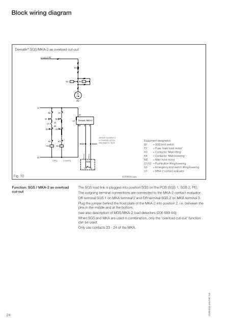
Block wiring diagram<br />
Dematik ® SGS/MKA-2 as overload cut-out<br />
Fig. 10<br />
L4<br />
L5<br />
L1,L2,L3 PE<br />
S2 S1<br />
S1 S2<br />
U1<br />
23<br />
24<br />
S3 S3<br />
K4 K3<br />
K3 K4<br />
Lifting Lowering<br />
Function: SGS / MKA-2 as overload<br />
cut-out<br />
F2<br />
K3 K4<br />
U1<br />
M<br />
3<br />
M2<br />
A1<br />
Dematik MKA-2<br />
A2 2 3<br />
SGS1 SGS2<br />
Brown<br />
Yellow<br />
SGS<br />
21 22<br />
Jumper in position 2<br />
= Overload cut-out<br />
(see page 23, fig 9)<br />
42356644.eps<br />
Equipment designation<br />
B1 = SGS limit switch<br />
F2 = Fuse ‘main <strong>hoist</strong> motor’<br />
K3 = Contactor ‘Main lifting’<br />
K4 = Contactor ‘Main lowering’<br />
M2 = Main <strong>hoist</strong> motor<br />
S1/S2 = Pushbutton lifting/lowering<br />
S3 = Emergency limit switch lifting/lowering<br />
U1 = MKA-2 contact evaluator<br />
The SGS load link is plugged into position SGS on the PCB (SGS 1, SGS 2, PE).<br />
The outgoing terminal connections are connected to the MKA-2 contact evaluator.<br />
<strong>DR</strong> terminal SGS 1 on MKA terminal 2 and <strong>DR</strong> terminal SGS 2 on MKA terminal 3.<br />
Plug the jumper behind the front plate of the MKA-2 into position 2, i.e. between the<br />
pins in the middle and at the bottom.<br />
(see also description of MGS/MKA-2 load detectors (206 689 44))<br />
When SGS and MKA are used in combination, only the ‘overload cut-out’ function<br />
can be used.<br />
Only use contacts 23 - 24 of the MKA.<br />
24 20364044.p65/081105