ANSYS Advantage • Volume II, Issue 2, 2008 - MESco
ANSYS Advantage • Volume II, Issue 2, 2008 - MESco
ANSYS Advantage • Volume II, Issue 2, 2008 - MESco

You also want an ePaper? Increase the reach of your titles
YUMPU automatically turns print PDFs into web optimized ePapers that Google loves.
ADVANTAGE<br />
EXCELLENCE IN ENGINEERING SIMULATION<br />
VOLUME <strong>II</strong> ISSUE 2 <strong>2008</strong><br />
PRODUCTS AND<br />
TECHNOLOGY SPOTLIGHT<br />
PAGE 9<br />
FLUID FLOW<br />
SIMULATION<br />
PAGE 17<br />
MULTIBODY<br />
DYNAMICS<br />
PAGE 20<br />
PAGE 4<br />
TM<br />
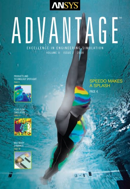
SPEEDO MAKES<br />
A SPLASH
EDITORIAL<br />
Don’t Isolate<br />
Engineering Simulation<br />
Leverage the tremendous value of the technology by tightly integrating<br />
simulation into your company’s product development process.<br />
The benefits of integrating simulation into engineering<br />
processes are well known. By making analysis a routine part<br />
of design — especially up front in the cycle — companies<br />
can spot and fix problems early, cut down on testing numerous<br />
physical prototypes, optimize product performance and<br />
create innovative designs that often would not be feasible<br />
without the use of simulation to explore alternative concepts.<br />
Software vendors across the board have been touting this<br />
message for years. Yet ironically — and unfortunately for the<br />
CAE user community — software from many vendors does<br />
not support such integration.<br />
One of the big problems is that many simulation<br />
programs are not interoperable with other software,<br />
especially with a broad range of CAD programs, other CAE<br />
technologies and data management tools. Because the<br />
architectures of these CAE programs are generally closed<br />
and rigid, programs simply don’t talk to one another and<br />
exchange information well. So users must go through inefficient<br />
and error-prone processes of converting data,<br />
reworking models, duplicating mesh representations and<br />
copying information from one system to another.<br />
Another difficulty is that the programs often are aimed<br />
solely at particular user skill levels and specific types of<br />
analyses, or they may run only on certain computers.<br />
Moreover, users may find that some software is not all it’s<br />
cracked up to be in handling the wide range of complex<br />
problems and real-world applications that engineers routinely<br />
encounter in their work. As a result, engineering simulation at<br />
many companies may be performed sporadically in isolation<br />
from other tools and groups throughout the organization —<br />
For <strong>ANSYS</strong>, Inc. sales information, call 1.866.267.9724, or visit www.ansys.com.<br />
For address changes, contact <strong>Advantage</strong>AddressChange@ansys.com.<br />
To subscribe to <strong>ANSYS</strong> <strong>Advantage</strong>, go to www.ansys.com/subscribe.<br />
Executive Editor<br />
Chris Hardee<br />
Managing Editor<br />
Chris Reeves<br />
Senior Editor and<br />
Industry Analyst<br />
John Krouse<br />
Art Director<br />
Susan Wheeler<br />
Editors<br />
Erik Ferguson<br />
Fran Hensler<br />
Marty Mundy<br />
Ad Sales Manager<br />
Shane Moeykens<br />
Graphics Contributor<br />
Maciej Ginalski<br />
Editorial Advisor<br />
Kelly Wall<br />
working against the full integration of analysis into product<br />
development processes and negating many of the potential<br />
benefits of the technology.<br />
Although such problems are rampant throughout the<br />
simulation industry, some software has been developed<br />
that takes the user community’s needs into consideration.<br />
Case in point can be found in this issue’s Spotlight on<br />
Products and Technology section covering the capabilities<br />
of simulation solutions from <strong>ANSYS</strong> Inc. An open architecture<br />
enables the software to work well with other programs<br />
through bi-directional CAD associativity, and direct links to<br />
other analysis solvers (including competitive programs)<br />
and product lifecycle management (PLM) systems. The<br />
software has been purposefully developed to be scalable<br />
across a wide range of users and computers. This enables<br />
companies to deploy simulation solutions in a flexible<br />
manner across the organization. It also enables users to<br />
drill down as deep as they need to in a broad range of<br />
disciplines — including the simulation industry’s most<br />
comprehensive multiphysics portfolio.<br />
In this way, innovative companies can implement<br />
advanced simulation technology in a completely integrated<br />
manner using a single platform and common infrastructure,<br />
while competitors struggle with piecemeal analysis<br />
and fragmented workflow isolated from the rest of the<br />
organization’s programs and processes. ■<br />
John Krouse, Senior Editor and Industry Analyst<br />
Email the editorial staff at ansys-advantage@ansys.com.<br />
<strong>ANSYS</strong> <strong>Advantage</strong> is published for <strong>ANSYS</strong>, Inc. customers, partners and others interested in the field of design and analysis applications.<br />
Neither <strong>ANSYS</strong>, Inc. nor the senior editor nor Miller Creative Group guarantees or warrants accuracy or completeness of the material contained in this publication.<br />
<strong>ANSYS</strong>, <strong>ANSYS</strong> Workbench, CFX, AUTODYN, FLUENT, DesignModeler, <strong>ANSYS</strong> Mechanical, DesignSpace, <strong>ANSYS</strong> Structural, TGrid, GAMBIT and any and all <strong>ANSYS</strong>, Inc.<br />
brand, product, service, and feature names, logos and slogans are registered trademarks or trademarks of <strong>ANSYS</strong>, Inc. or its subsidiaries located in the United States<br />
or other countries. ICEM CFD is a trademark licensed by <strong>ANSYS</strong>, Inc. All other brand, product, service and feature names or trademarks are the property of their<br />
respective owners.<br />
© <strong>2008</strong> <strong>ANSYS</strong>, Inc. All rights reserved.<br />
Designer<br />
Miller Creative Group<br />
Circulation Managers<br />
Elaine Travers<br />
Sharon Everts<br />
Production Assistant<br />
Joan Johnson<br />
About the Cover<br />
Speedo takes advantage<br />
of simulation in designing<br />
a new swimsuit.
CONTENTS<br />
2<br />
Table of Contents<br />
4<br />
24<br />
26<br />
<strong>ANSYS</strong> <strong>Advantage</strong> <strong>•</strong> <strong>Volume</strong> <strong>II</strong>, <strong>Issue</strong> 2, <strong>2008</strong><br />
9<br />
17<br />
FEATURES<br />
4 SPORTS<br />
Simulating Swimwear for<br />
Increased Speed<br />
Speedo’s new full-body swimsuit takes advantage of simulation<br />
technology in pursuit of gold medals and world records.<br />
7 NEWS<br />
<strong>ANSYS</strong> Signs Agreement to<br />
Acquire Ansoft<br />
The complementary business combination of <strong>ANSYS</strong> and<br />
Ansoft will create the leading provider of best-in-class<br />
simulation capabilities.<br />
Spotlight on Engineering Simulation<br />
Products and Technology<br />
9 Engineering Simulation for<br />
the 21st Century<br />
Five key principles guide the development of simulation<br />
products and technology at <strong>ANSYS</strong>.<br />
12 Putting Engineering Knowledge to Work<br />
New technology enables efficient sharing of rich simulation<br />
information and provides enterprise-wide benefits.<br />
14 Applying Six Sigma to Drive Down<br />
Product Defects<br />
Probabilistic design and sensitivity analyses help engineers<br />
quickly arrive at near-zero product failures in the face of wide<br />
manufacturing variabilities and other uncertainties.<br />
17 The New Wave of Fluids Technology<br />
Fluid flow simulation software from <strong>ANSYS</strong> provides<br />
a broad range of scalable solutions.<br />
20 Multibody Dynamics: Rigid, Flexible<br />
and Everything in Between<br />
Advances in simulation solutions for machine features<br />
accommodate more complex designs.<br />
24 Nonlinear Simulation Provides More<br />
Realistic Results<br />
When parts interact and experience large deflections and<br />
extreme conditions, nonlinear technology is required to<br />
simulate real-life situations.<br />
26 High Performance from Multiphysics<br />
Coupled Simulation<br />
Engineers use <strong>ANSYS</strong> Multiphysics to study the mechanical<br />
strength and thermal performance of an innovative<br />
thermoelectric cooler design.<br />
www.ansys.com
SIMULATION @ WORK<br />
29 MARINE<br />
Getting the Mast from<br />
Virtual Prototyping<br />
Structural simulation tools help optimize main mast<br />
weight to increase megayacht sailing performance.<br />
31 ELECTROMAGNETICS<br />
Predicting Charged Particle Trajectories<br />
Simulation helps researchers obtain electromagnetic field<br />
solutions for predicting charged particle trajectories in a wide<br />
range of industrial, medical and research applications.<br />
35 CONSUMER PRODUCTS<br />
Flush with Success<br />
A toilet discharge valve is optimized to reduce household<br />
water consumption and maintain performance.<br />
36 TRANSPORTATION<br />
Adapting A High-Speed Train<br />
to Winter in Russia<br />
Simulation helps prevent traction problems for<br />
rail travel during extreme weather conditions.<br />
38 BIOMEDICAL<br />
Understanding the Dangers<br />
of Aneurysms<br />
Simulation is used to validate measured<br />
blood flow in cerebral aneurysms.<br />
Thanks for Helping Us Navigate<br />
38<br />
DEPARTMENTS<br />
CONTENTS<br />
40 BOOK REVIEWS<br />
Learning to Work with<br />
<strong>ANSYS</strong> Workbench<br />
Tutorials help novices and experienced users alike<br />
understand the ins and outs of this simulation platform.<br />
42 ACADEMIC<br />
Simulation-Driven Teaching<br />
and Research<br />
Academic products from <strong>ANSYS</strong> at release 11.0 are<br />
helping train future engineers.<br />
46 TIPS & TRICKS<br />
Using New Meshing Features in<br />
<strong>ANSYS</strong> Workbench Simulation<br />
Knowing when and how to apply key features of the latest<br />
structural meshing tools can result in greater efficiency.<br />
49 TIPS & TRICKS<br />
Coupling Momentum and Continuity<br />
Increases CFD Robustness<br />
FLUENT technology introduces a pressure-based coupled<br />
solver to reduce computation time for low-speed<br />
compressible and incompressible flow applications.<br />
52 OUTSIDE THE BOX<br />
Fluid Dynamics on the Big Screen<br />
Fluid simulations have come of age in the world<br />
of movie-making.<br />
Recently we asked you, the readers of <strong>ANSYS</strong> <strong>Advantage</strong>, for help in charting the magazine’s path to the future.<br />
Your response was overwhelming. Thanks for taking the time to share your opinions and comments.<br />
We now have a better understanding of your needs and are already implementing some of your suggestions. You’ll<br />
see some changes to the magazine in this and upcoming issues. For instance, we’ve already started a new section —<br />
Outside the Box — which, in each issue, will report on some aspect of simulation with a human interest slant.<br />
We hope you enjoy it. Other changes will be coming in subsequent issues.<br />
As for the winners of the navigation prizes — GPS unit and compasses — they were Stéphane Trehorel of Geo<br />
Technology S.A., Andreas Wiese of ELAU AG and Stefan Jelenko of Litostroj E.I. Congratulations!<br />
Although the survey is officially over, we are always happy to receive your suggestions or your article submissions.<br />
Send an email to ansys-advantage@ansys.com at any time. We look forward to hearing from you.<br />
www.ansys.com <strong>ANSYS</strong> <strong>Advantage</strong> <strong>•</strong> <strong>Volume</strong> <strong>II</strong>, <strong>Issue</strong> 2, <strong>2008</strong> 3<br />
52
FEATURE: SPORTS<br />
Simulating Swimwear<br />
for Increased Speed<br />
Speedo’s new full-body swimsuit takes advantage of simulation<br />
technology in pursuit of gold medals and world records.<br />
By Leigh Bramall, PR Specialist, <strong>ANSYS</strong>, Inc.<br />
Most of us are familiar by now with the use of simulation in<br />
sports such as Formula One racing, NASCAR ® and, more<br />
recently, America’s Cup yacht racing. The potential applications<br />
are obvious with aerodynamics on a racing car or<br />
hydrodynamics on a yacht. But the use of simulation technology<br />
is spreading far beyond these more obvious applications.<br />
Swimwear designer and manufacturer Speedo ® is a<br />
name synonymous with the pool and swimming competition.<br />
The company has an 80-year history of developing swimsuits<br />
for elite swimmers, all the while successfully maintaining its<br />
leading position in the industry. In the 1920s, Speedo made<br />
history with the Racerback — the world’s first non-wool suit.<br />
More recently, the company introduced the full-body swimsuit<br />
to the competitive swimming arena with its FASTSKIN ®<br />
suit, which was designed to reduce drag and optimize<br />
performance and was worn by the majority of competitors at<br />
the 2000 Sydney Olympics.<br />
Computational fluid dynamics (CFD) first entered the<br />
sport of competitive swimming in a significant way with the<br />
development of Speedo’s FASTSKIN FS<strong>II</strong> swimsuit, developed<br />
for use at the 2004 Athens Olympics. February <strong>2008</strong><br />
saw the further development of Speedo’s CFD program with<br />
the global launch of its LZR RACER ® suit ahead of the<br />
Beijing games. Using FLUENT technology from <strong>ANSYS</strong>, Inc.,<br />
Speedo used CFD analysis to guide, test and refine the final<br />
design of the suit, bringing together a range of research with<br />
the goal of improving performance.<br />
4<br />
<strong>ANSYS</strong> <strong>Advantage</strong> <strong>•</strong> <strong>Volume</strong> <strong>II</strong>, <strong>Issue</strong> 2, <strong>2008</strong><br />
The LZR RACER suit is the result of three years of work<br />
conducted by Aqualab, Speedo’s own in-house R&D group.<br />
Headed by Jason Rance, the Aqualab ® group oversaw a<br />
research program that employed multiple partners — the University<br />
of Otago in New Zealand, the University of Nottingham<br />
in the United Kingdom, the Australian Institute of Sport,<br />
Optimal Solutions in the United States, NASA in the United<br />
States and <strong>ANSYS</strong>. The outcome is a swimsuit that has<br />
10 percent less passive drag than the FASTSKIN FS<strong>II</strong> suit and<br />
38 percent less passive drag than an ordinary LYCRA ® suit.<br />
To begin the research, the team attempted to identify the<br />
fabric with the least possible drag. They started by taking<br />
body scans of more than 400 elite swimmers to provide<br />
geometries for testing more than 100 different fabrics and<br />
suit designs. Work focused on developing two different<br />
fabrics: LZR Pulse ® , an ultra-lightweight, powerful, lowdrag,<br />
water repellent, fast-drying fabric to be used as the base<br />
woven material for the suit; and LZR panels made of a<br />
low-drag, ultra-powerful polyurethane membrane to be<br />
bonded onto the base woven material to reduce drag at<br />
specific high-drag locations.<br />
To test the fabrics and create a suit with the lowest drag,<br />
the Speedo researchers used one of the world’s most<br />
advanced water flumes at the University of Otago. NASA<br />
also was employed, with the space agency evaluating the<br />
surface friction of fabric candidates in its low-speed wind<br />
tunnel. The wind tunnel was operated at 28 meters per<br />
www.ansys.com
second to simulate a swimmer moving at 2 meters per second<br />
in water. NASA used a smooth aluminium plate as a<br />
benchmark for the fabric tests. Results showed that the<br />
smoothest fabric had the lowest drag, with the final fabric<br />
chosen for the LZR panel producing test results comparable<br />
to the drag results for the aluminium plate.<br />
Following the water flume and wind tunnel tests, the<br />
Speedo team put the results into practice in the real world at<br />
the Australian Institute of Sport, conducting time-trials with<br />
swimmers wearing the new suit and standard training wear.<br />
The drag reductions identified in the water flume and wind<br />
tunnel translated to a 4 percent increase in speed for swimmers<br />
when wearing the new suit as opposed to wearing<br />
training swimwear. The new suit also delivered a 5 percent<br />
improvement in the swimmers’ oxygen utilization when<br />
compared to trials performed in the training wear. These<br />
efficiencies are significant in a sport in which success or<br />
failure can be measured in hundredths of a second.<br />
The Speedo team took further steps to reduce drag at<br />
every opportunity. They designed the suit to achieve a<br />
compression effect through the tensile properties of the<br />
materials — powerful fabrics that compress key body areas.<br />
Effectively, these features help to mold the swimmer’s body<br />
into a more streamlined shape, reducing the hydrodynamic<br />
profile and minimizing oscillations in muscles that might<br />
disturb flow. The team also used ultrasonic welding to bind<br />
the material sections of the suit together, eliminating all<br />
seams that could disturb flow and induce drag.<br />
For further analysis, <strong>ANSYS</strong> performed CFD studies<br />
in association with Dr. Herve Morvan of the University of<br />
Nottingham. The focus was on passive drag, which occurs<br />
when the body is in the glide position with arms outstretched<br />
in front and legs outstretched behind. Swimmers<br />
maintain this position for up to 15 meters immediately<br />
after diving and for a similar period after kicking off under<br />
water following each turn. For this reason, this position is<br />
critically important in a competitive race situation. Testing<br />
focused on this position, providing indications of overall<br />
performance of the suit during racing conditions.<br />
The researchers used CFD analyses to identify areas in<br />
which both skin- and form-drag occur. Skin-drag is inherent<br />
in swimsuit material properties, since fluid flows over the<br />
fabric, and in local flow conditions, speed in particular. It is<br />
induced by the local velocity gradients that create a shear<br />
force due to the viscous properties of the fluid. Form-drag,<br />
on the other hand, is a result of the swimmer’s body<br />
Pressure contours around an elite male swimmer wearing a LZR RACER suit in the glide position<br />
FEATURE: SPORTS<br />
Six-time Olympic gold medalist and American swimming sensation Michael Phelps in the<br />
glide position<br />
traveling through the fluid; the goal is to make the flow path<br />
as smooth and undisturbed as possible, thereby decreasing<br />
the drag. The CFD simulations involved precise boundary<br />
layer meshing techniques using software from <strong>ANSYS</strong> and<br />
resolved fine fluid flow details using the precision scanned<br />
geometries of elite swimmers. Speedo carried out all of<br />
these CFD studies as part of ongoing research conducted<br />
since the 2004 Olympics in Athens.<br />
www.ansys.com <strong>ANSYS</strong> <strong>Advantage</strong> <strong>•</strong> <strong>Volume</strong> <strong>II</strong>, <strong>Issue</strong> 2, <strong>2008</strong> 5
FEATURE: SPORTS<br />
6<br />
Flow pathlines colored by local flow velocity around an elite male swimmer wearing a LZR RACER suit in the glide position<br />
Using the wealth of detailed fluid dynamics data from<br />
the CFD studies generated with software from <strong>ANSYS</strong>,<br />
Speedo researchers were able to guide the final design<br />
of the new suit — in particular, the precise location of<br />
the ultra-low-drag LZR panels, which were bonded<br />
onto the LZR RACER suit. In the end, the strategically<br />
placed LZR panels were found to reduce skin drag<br />
by a startling 24 percent in comparison to Speedo’s<br />
previous FASTSKIN fabric.<br />
Dr. Keith Hanna of <strong>ANSYS</strong>, who lectures on the<br />
application of CFD technology in sport, believes the<br />
scope for the application of CFD and simulation in<br />
general will only increase in the future. Hanna<br />
stated, “CFD is a powerful technology, and the<br />
accuracy of the results from this study have given<br />
Speedo confidence in the benefits of applying CFD<br />
in the design of future swimsuits. However, the big<br />
development in years to come could be the use of<br />
comprehensive multiphysics technology for elite<br />
swimsuit development — that is, the use of CFD<br />
with other physics such as structural simulation to<br />
actually simulate every aspect of real-world physics<br />
found in a competitive swimming scenario.<br />
“The physics involved in simulating a moving<br />
swimmer are extremely complex, but the potential is<br />
there. Industries such as aerospace and automotive<br />
are increasingly turning to a multiphysics simulation<br />
solution as the only way of ensuring that all parameters<br />
are accounted for in their design process. In the instance<br />
of simulating performance in competitive swimming, a<br />
multiphysics approach would mean not only that CFD be<br />
used to analyze hydrodynamic flow and drag around a<br />
swimmer, but also that structural software be used to simulate<br />
how the suit itself may deform during a swimming<br />
stroke, for example, and how this affects drag.” ■<br />
In the first ten weeks following its launch in February, swimmers wearing<br />
the Speedo LZR RACER swimsuit set 35 world records.<br />
<strong>ANSYS</strong> <strong>Advantage</strong> <strong>•</strong> <strong>Volume</strong> <strong>II</strong>, <strong>Issue</strong> 2, <strong>2008</strong><br />
Surface shear stress contours on an elite male athlete in the glide position<br />
www.ansys.com
<strong>ANSYS</strong> Signs Agreement<br />
to Acquire Ansoft<br />
The complementary business combination of <strong>ANSYS</strong> and Ansoft<br />
will create the leading provider of best-in-class simulation capabilities.<br />
<strong>ANSYS</strong>, Inc. and Ansoft Corporation,<br />
a global provider of electronic<br />
design automation (EDA) software,<br />
announced on March 31 that a definitive<br />
agreement was signed in which <strong>ANSYS</strong><br />
will acquire Ansoft for a purchase price<br />
of approximately $832 million. Ansoft is<br />
a leading developer of high-performance<br />
EDA software, which is based on more<br />
than 25 years of research and development<br />
by world-renowned experts in<br />
electromagnetics, circuit and system<br />
simulation. Engineers use Ansoft<br />
products to simulate high-performance<br />
electronics designs found in mobile<br />
communication and Internet devices,<br />
broadband networking components and<br />
systems, integrated circuits, printed<br />
circuit boards and electromechanical<br />
systems. Products from Ansoft are used<br />
by blue chip companies as well as small<br />
and medium-sized enterprises around<br />
the world.<br />
The acquisition of Ansoft is the first<br />
foray for <strong>ANSYS</strong> into the broader EDA<br />
software industry and will enhance the<br />
breadth, functionality, usability and<br />
interoperability of the combined <strong>ANSYS</strong><br />
portfolio of engineering simulation solutions.<br />
The combination is expected to<br />
increase operational efficiency and<br />
lower design and engineering costs<br />
for customers, as well as accelerate<br />
development and delivery of new and<br />
innovative products to the marketplace;<br />
it also is expected to give <strong>ANSYS</strong> one<br />
of the most complete, independent<br />
engineering simulation software offerings<br />
in the industry. This reaffirms and<br />
strengthens the <strong>ANSYS</strong> commitment to<br />
open interface and flexible simulation<br />
solutions that are driven primarily by<br />
customer demand, flexibility and choice.<br />
With more than 40 direct sales offices<br />
and 21 development centers on three<br />
continents, the combined company will<br />
employ approximately 1,700 people.<br />
“We are very excited about the<br />
state-of-the-art technologies that Ansoft<br />
adds to the simulation capabilities of<br />
<strong>ANSYS</strong>,” said James E. Cashman <strong>II</strong>I,<br />
president and chief executive officer of<br />
<strong>ANSYS</strong>, Inc. “Both companies have a<br />
strong commitment to their customers<br />
and employees, share a passion for<br />
the development of innovative products<br />
and services, and have a history of<br />
world-class execution. It expands our<br />
offerings into electronic designs, a<br />
critical area. Now we can bring the richest<br />
engineering calculations to predict<br />
how a product will perform in the real<br />
world. Electronics and the electromagnetic<br />
field are obviously a big part of<br />
that. With Ansoft, we can take a complete<br />
system and the entire environment<br />
NEWS<br />
and allow designers to evaluate their<br />
entire product.”<br />
“This merger brings together two<br />
great companies with a shared vision<br />
and strong engineering focus,” said Dr.<br />
Zoltan J. Cendes, the founder, chairman<br />
of the board and chief technology officer<br />
of Ansoft Corporation. “The combination<br />
of our R&D teams, complementary<br />
technological strengths and commitment<br />
to quality will enhance our ability<br />
to deliver comprehensive, innovative,<br />
world-class simulation software technologies<br />
that customers demand.”<br />
“We are excited about bringing two<br />
great Pittsburgh-based companies<br />
together to create an exciting opportunity<br />
for aspiring engineers, computer<br />
scientists and professionals to join us<br />
in our mission to democratize the<br />
use of simulation across the globe,”<br />
added Cashman. ■<br />
www.ansys.com <strong>ANSYS</strong> <strong>Advantage</strong> <strong>•</strong> <strong>Volume</strong> <strong>II</strong>, <strong>Issue</strong> 2, <strong>2008</strong> 7
8<br />
<strong>ANSYS</strong> <strong>Advantage</strong> <strong>•</strong> <strong>Volume</strong> <strong>II</strong>, <strong>Issue</strong> 2, <strong>2008</strong><br />
www.ansys.com
PRODUCTS & TECHNOLOGY: OVERVIEW<br />
Engineering Simulation<br />
for the 21st Century<br />
Five key principles guide the development of<br />
simulation products and technology at <strong>ANSYS</strong>.<br />
By Chris Reid, Vice President, Marketing, <strong>ANSYS</strong>, Inc.<br />
Technology is the lifeblood of <strong>ANSYS</strong>, Inc., and the basis<br />
for everything we offer our customers. For more than 35<br />
years, <strong>ANSYS</strong> has been a pioneer in the application of finite<br />
element methods to solve the engineering design challenges<br />
our customers face. During that time, the evolution of our<br />
industry, products and technology has been nothing short of<br />
amazing. Fueled by a corresponding increase in the powerto-price<br />
ratio of the computing world, the problem size<br />
and complexity of simulations have grown to impressive<br />
dimensions. The net effect of this is evident in almost every<br />
facet of life — from the cars we drive to the energy we use, the<br />
products we buy, the air we breathe and even the devices we<br />
insert into our bodies to maintain our health.<br />
How have we accomplished this near 40-year run of<br />
groundbreaking achievement in engineering simulation and<br />
modeling? Staying true to our vision and strategy has<br />
certainly been a major factor. Unlike others, <strong>ANSYS</strong> has never<br />
wavered from its core business of engineering simulation<br />
software. Instrumental to that vision is our commitment to<br />
advanced technology — the cornerstone of our business and<br />
www.ansys.com <strong>ANSYS</strong> <strong>Advantage</strong> <strong>•</strong> <strong>Volume</strong> <strong>II</strong>, <strong>Issue</strong> 2, <strong>2008</strong> 9
PRODUCTS & TECHNOLOGY: OVERVIEW<br />
value to our customers. After all, it is our products and<br />
technology that enable companies to create the most<br />
innovative and globally competitive products for<br />
their industry.<br />
Also instrumental to our vision are five principles<br />
that guide the development of our products and technologies.<br />
The first is unequalled depth. Simply stated,<br />
for each of the key areas of simulation and modeling<br />
technologies — whether it be mechanical, fluid flow,<br />
thermal, electromagnetics, meshing or others — we<br />
offer a depth of capability that is second to none. This<br />
depth has been created over time by reinvesting in<br />
the research and development of new technologies,<br />
and supplemented by key acquisitions and partnerships<br />
along the way. Today, the results speak for<br />
themselves in the richness of what we offer our customers,<br />
regardless of their specific simulation<br />
requirements.<br />
The second guiding principle is unparalleled<br />
breadth. In this regard, <strong>ANSYS</strong> has assembled a<br />
complete range of simulation capabilities — from preprocessing<br />
to multiple physics to knowledge<br />
management. Our customers see this as a tremendous<br />
benefit, because they know we can provide a<br />
solution for each specific area of analysis and that we<br />
provide rich depth across our entire portfolio of products<br />
and technologies. Some companies, perhaps,<br />
can lay claim to this in one or two areas, but we offer<br />
this depth and breadth for the full range of simulation<br />
and modeling techniques.<br />
In offering both technological depth and breadth,<br />
our customers are able to run simulations that<br />
are more sophisticated, more complex and more<br />
representative of the real world. Utilizing such a<br />
comprehensive multiphysics approach — our third<br />
guiding principle — enables engineers to simulate and<br />
analyze complete systems or subsystems using true<br />
virtual prototyping. Increasingly, companies realize that<br />
a multiphysics approach is essential to attain the most<br />
accurate and realistic simulation of a new product or<br />
process design. At <strong>ANSYS</strong>, we not only provide<br />
the technologies to do this, but we make them all<br />
interoperable within the unified <strong>ANSYS</strong> Workbench<br />
environment. Thus, the user can configure a<br />
multiphysics analysis and avoid the need for cumbersome<br />
file transfers or intermediate third-party<br />
software links. Our technology inherently provides the<br />
infrastructure, saving implementation time while<br />
providing measurable benefits in speed and robustness<br />
as well.<br />
The old adage “one size fits all” is certainly not<br />
the case in the world of engineering simulation.<br />
Despite the common threads that appear everywhere<br />
simulation is used, there are also real differences.<br />
Some industries, such as automotive and aerospace,<br />
are mature in their use of these tools, while others,<br />
such as healthcare, are relative newcomers. Companies<br />
within the same industry can be at markedly<br />
different stages of adoption, and users within any one<br />
company may have vastly different needs or experience<br />
with simulation tools. There is a need for<br />
flexibility. Customers must be able to adopt the<br />
appropriate level of simulation and know they will<br />
have latitude in how they move forward.<br />
At <strong>ANSYS</strong>, we call this engineered scalability —<br />
guiding principle number four. Why “engineered”?<br />
Our scalability is by design and is specifically engineered<br />
into the technology we have developed. The<br />
depth of our technology allows customers to choose<br />
the appropriate level of technology for their needs yet<br />
scale upward as their requirements evolve and grow.<br />
If the customer is a small company with just a desktop<br />
or modest compute resources, or if it is large with<br />
hundreds of machines in large-scale compute clusters,<br />
our software runs efficiently and brings value. In<br />
a similar vein, if the number of users is very small or in<br />
the hundreds, scalable deployment has been factored<br />
in. Likewise, if the customer is an infrequent user, a<br />
designer who wants to perform a simple simulation or<br />
an expert analyst, we have the appropriate level of<br />
tool for each of those levels of experience. Underpinning<br />
this seamless range of capability — from the<br />
automated to the most sophisticated and customizable<br />
— is the same advanced technology, scaled up<br />
or down accordingly.<br />
Technology isn’t of much use to the customer if it’s<br />
extremely inflexible to apply, scalable or otherwise. All<br />
of it must be usable in a way that makes sense for the<br />
company and its design and development processes,<br />
as well as alongside other programs it may have<br />
selected for their engineering systems strategy. The<br />
vision needs to be flexible and adaptive, not rigid and<br />
constraining. In this regard, <strong>ANSYS</strong> adheres to a fundamental<br />
tenet of adaptive architecture — the fifth<br />
10 <strong>ANSYS</strong> <strong>ANSYS</strong> <strong>Advantage</strong> <strong>Advantage</strong> <strong>•</strong> <strong>•</strong> <strong>Volume</strong> <strong>Volume</strong> <strong>II</strong>, <strong>II</strong>, <strong>Issue</strong> <strong>Issue</strong> 2, 1, <strong>2008</strong><br />
<strong>2008</strong><br />
www.ansys.com
guiding principle. We recognize the mission-critical<br />
nature of what we provide and also how crucial it is<br />
that our technology fits within the customer’s overall<br />
system. There can be CAD systems, selected thirdparty<br />
codes for niche applications, or legacy and<br />
in-house software, all of which remain critical components<br />
of the overall process. We need to coexist with<br />
these and, in fact, enable them to be included in the<br />
overall workflow as painlessly as possible.<br />
Many companies are investing in product lifecycle<br />
management (PLM) systems. These constitute a major<br />
investment and require data exchange with the<br />
simulation software. The <strong>ANSYS</strong> Workbench platform<br />
and the new <strong>ANSYS</strong> Engineering Knowledge Manager<br />
(EKM) technology are designed to provide functional<br />
coexistence with PLM systems, which actually<br />
improves their value to the customer. Adaptive<br />
architecture means what it says — <strong>ANSYS</strong> products<br />
and technology can adapt to the customer’s specific<br />
PRODUCTS & TECHNOLOGY: OVERVIEW<br />
situation. We can be the backbone, coexist peer-topeer<br />
or be a plug-in, whatever the need may be.<br />
Five simple phrases — unequalled depth, unparalleled<br />
breadth, comprehensive multiphysics, engineered<br />
scalability and adaptive architecture. These five tenets<br />
are what drive our product development strategy with<br />
every dollar we invest. We also think they are the reason<br />
that 96 of the top 100 industrial companies on the<br />
FORTUNE Global 500 list, as well as another 13,000<br />
customers around the world, use technology from<br />
<strong>ANSYS</strong>. The <strong>ANSYS</strong> simulation community today is<br />
the world’s largest, and by continuing to pursue our<br />
strategy of Simulation Driven Product Development and<br />
adhering to these five guiding principles, we see no<br />
reason why our vision of placing simulation tools in the<br />
hands of every engineer shouldn’t become a reality in<br />
the near future. ■<br />
Images courtesy Tusas Engine Industries, Silesian University of Technology, Cummins,<br />
Inc., FluidDA nv, Modine Manufacturing Company and © <strong>2008</strong> Owens Corning<br />
Science & Technology, LLC and the Gas Technology Institute. Used with permission.<br />
www.ansys.com <strong>ANSYS</strong> <strong>Advantage</strong> <strong>•</strong> <strong>Volume</strong> <strong>II</strong>, <strong>Issue</strong> 2, <strong>2008</strong> 11
PRODUCTS & TECHNOLOGY: DATA MANAGEMENT<br />
Putting Engineering<br />
Knowledge to Work<br />
New technology enables efficient sharing of rich simulation<br />
information and provides enterprise-wide benefits.<br />
By Michael Engelman, Vice President, Business Development, <strong>ANSYS</strong>, Inc.<br />
The last three decades have witnessed the evolution of<br />
computer-aided engineering (CAE) from a tool used by<br />
analysts in a research and development department to one<br />
that is integral to the entire product design and lifecycle<br />
process. Companies around the world are making greater<br />
use of upfront analysis and complex system simulation.<br />
With the ongoing integration of CAE into the design<br />
process, the focus is shifting from technology issues such<br />
as improved simulation techniques, physics modeling and<br />
ease-of-use to usage-focused questions such as “How do<br />
I better manage and share the voluminous data that is being<br />
generated?” or “How do I better capture the engineering<br />
expertise that the simulation results represent?” The answer<br />
to these questions is often referred to as simulation process<br />
and data management (SPDM).<br />
SPDM presents a whole new set of challenges to CAE<br />
practitioners. The current focus centers on accessibility —<br />
that is, how do the right people get the right data at the right<br />
time? More often than not, keeping track of this information is<br />
left to the individual analyst or engineer who generated it, so<br />
typically at the end of a project it is buried in obscurity somewhere<br />
on a hard drive. According to a recent survey by<br />
Collaborative Product Development Associates (CPDA), 47<br />
percent of all simulation results are stored on the engineer’s<br />
local workstation. This valuable intellectual property is usually<br />
lost forever when individuals leave a team or company. As<br />
anyone who has tried knows, tracking down old data files and<br />
analysis models from past simulation projects is difficult<br />
or often impossible, even for the people who created them.<br />
Consequently, simulations are often redone from scratch —<br />
rather than by performing a simple modification to an existing<br />
case or model. The result is a significant loss in time<br />
and productivity.<br />
With rapid globalization now permeating all aspects of<br />
many companies’ operations, engineering groups located at<br />
different locations around the world constitute virtual<br />
24-hour-a-day development organizations. Effective collaboration<br />
and communication are essential to support this<br />
global mode of operation. Ineffective communication hurts<br />
the entire team, from the engineer who is trying to explain<br />
design challenges and concerns to his or her manager, to the<br />
teams that need to consider external factors affecting their<br />
development process and design. Using tools that can help<br />
12<br />
<strong>ANSYS</strong> <strong>Advantage</strong> <strong>•</strong> <strong>Volume</strong> <strong>II</strong>, <strong>Issue</strong> 2, <strong>2008</strong><br />
Commercial<br />
PDM<br />
Legacy database<br />
and in-house<br />
solution*<br />
Database and<br />
templates for<br />
most tasks<br />
Database for some<br />
simulation tasks*<br />
Simulation data<br />
management<br />
Other<br />
Data management methods<br />
Other<br />
Knowledge exchange methods<br />
User’s local<br />
machine*<br />
*Results in data loss<br />
Verbal and<br />
informal<br />
exchange*<br />
*Results in<br />
information loss<br />
convey simulation results to all members of a team at every<br />
level across the enterprise — regardless of their technical<br />
background — can dramatically boost the effectiveness of<br />
the team, the product development process and, finally, the<br />
quality and performance of the product.<br />
Corporate knowledge is a key business asset in a company’s<br />
quest for innovation and competitive advantage.<br />
Creating, capturing and managing a company’s simulation<br />
www.ansys.com
Pressure data for airflow over an aircraft wing is extracted using <strong>ANSYS</strong> EKM data<br />
mining capabilities.<br />
expertise is critical to enabling innovation. It empowers users<br />
to build on previous experience and fosters continual<br />
improvement and collaboration of the expert analysts and<br />
design engineers. Effective process management tools that<br />
capture simulation best practices, deploy managed simulation<br />
tasks and processes, and plug into internal applications<br />
within a unified environment are essential to achieve these<br />
goals — though they must also require minimal effort and<br />
maintenance costs.<br />
Managing simulation data and processes within this<br />
context is a specialized subset of the broader product<br />
lifecycle management (PLM) vision. This discipline is based on<br />
the digital management of all aspects of a product’s lifecycle,<br />
from concept and design through manufacture, deployment,<br />
maintenance and eventual disposal. Unfortunately, those<br />
needs that are specific to simulation and SPDM are often<br />
overlooked or poorly addressed by today’s PLM systems. This<br />
is a result of SPDM being more demanding than the file/<br />
document-centric approach of PLM and related product data<br />
management (PDM) systems. Simulation data is richer, more<br />
complex and typically many orders of magnitude larger than<br />
Process workflows can be mapped out and displayed in diagram style, as shown here.<br />
Among other possibilities, each step may be customized by the user to include<br />
automated substeps, assign team members tasks and iterate to the next step.<br />
PRODUCTS & TECHNOLOGY: DATA MANAGEMENT<br />
Comparison reports provide users, even those without a technical and simulation<br />
background, with the ability to examine simulation results.<br />
other types of product data. An SPDM system is complementary<br />
to a PLM system and can add significant value when<br />
designed to work in close conjunction with PLM.<br />
The <strong>ANSYS</strong> Engineering Knowledge Manager (EKM)<br />
technology, now in its initial release, is aimed at meeting these<br />
challenges with extensive capabilities: archiving and management<br />
of simulation data, traceability and audit trail, advanced<br />
search and retrieval, report generation and simulation comparison,<br />
process/workflow automation, and capture and<br />
deployment of best practices. It is a Web-based SPDM<br />
framework aimed at hosting all simulation data, workflows<br />
and tools, whether in-house or commercial, while maintaining<br />
a tight connection between them. While providing seamless<br />
integration with simulation products from <strong>ANSYS</strong> — including<br />
the ability to automatically extract and organize extensive<br />
information about <strong>ANSYS</strong> software–based simulation files<br />
when they are uploaded into the repository — the <strong>ANSYS</strong><br />
EKM tool is an open system that can manage any type of<br />
in-house or third-party simulation products, files or information<br />
as well. Moreover, it is a scalable solution that can be<br />
effectively used by small workgroups, distributed teams of<br />
engineers or the entire enterprise.<br />
With tools and developers that have histories stretching<br />
back to the formative years of simulation, <strong>ANSYS</strong> understands<br />
the complexity and challenges of simulation. <strong>ANSYS</strong><br />
EKM technology was created with an appreciation that<br />
access to simulation; developing effective processes for<br />
incorporating simulation into individual, workgroup and<br />
enterprise-wide efforts; and managing simulation efforts<br />
within a larger development or industrial process is a complicated<br />
effort — one that can be made simpler. Having access<br />
to the right tools, developed by a team that has devoted years<br />
to understanding the challenges of simulation, can streamline<br />
the incorporation of virtual product development efforts into<br />
traditional workflows and environments. Adding <strong>ANSYS</strong> EKM<br />
tools to the capabilities of the family of products from <strong>ANSYS</strong><br />
empowers organizations of all sizes to better achieve the<br />
goal of Simulation Driven Product Development. ■<br />
www.ansys.com <strong>ANSYS</strong> <strong>Advantage</strong> <strong>•</strong> <strong>Volume</strong> <strong>II</strong>, <strong>Issue</strong> 2, <strong>2008</strong> 13
PRODUCTS & TECHNOLOGY: DESIGN FOR SIX SIGMA<br />
Applying Six Sigma<br />
to Drive Down<br />
Product Defects<br />
Probabilistic design and sensitivity analyses help engineers<br />
quickly arrive at near-zero product failures in the face of<br />
wide manufacturing variabilities and other uncertainties.<br />
By Andreas Vlahinos, President, Advanced Engineering Solutions, Colorado, U.S.A.<br />
14<br />
Andreas Vlahinos<br />
<strong>ANSYS</strong> <strong>Advantage</strong> <strong>•</strong> <strong>Volume</strong> <strong>II</strong>, <strong>Issue</strong> 2, <strong>2008</strong><br />
Companies often are focused<br />
primarily on time-to-market, but the<br />
advantages of fast product introductions<br />
may be quickly overshadowed by<br />
the huge cost of poor quality, resulting<br />
in product recalls, rework, warranty<br />
payments and lost business from<br />
negative brand image.<br />
In many cases, such quality problems<br />
are the result of variations in<br />
factors such as customer usage,<br />
manufacturing, suppliers, distribution,<br />
delivery, installation or degradation<br />
over the life of the product. In general,<br />
such variations are not taken into consideration<br />
as part of the development<br />
of the product. Rather, the integrity and<br />
reliability of a design is typically based<br />
on an ideal set of assumptions that<br />
may be far removed from actual realworld<br />
circumstances. The result is a<br />
design that may be theoretically sound<br />
but riddled with defects once it is<br />
manufactured and in use.<br />
Design for Six Sigma (DFSS) is a<br />
statistical method for radically reducing<br />
these defects by developing designs<br />
that deliver a given target performance<br />
despite these variations. The approach<br />
is a measure of quality represented as<br />
the number of standard deviations<br />
away from a statistical mean of a target<br />
performance value. Operating at three<br />
sigma translates into about 67,000<br />
defects per million parts, performance<br />
typical of most manufacturers. A rating<br />
of six sigma equates to just 3.4 defects<br />
per million, or virtually zero defects.<br />
Achieving this level of quality<br />
requires a focused effort upfront in development,<br />
with design optimization driven<br />
by integration of DFSS into the process<br />
and rigorous use of simulation. In such<br />
DFSS efforts, <strong>ANSYS</strong> DesignXplorer<br />
software is a particularly valuable<br />
tool. Working from within the <strong>ANSYS</strong><br />
Workbench platform and in conjunction<br />
with <strong>ANSYS</strong> Mechanical and other<br />
<strong>ANSYS</strong> Mechanical parametric model of a gasket is automatically changed for each of the 10,000 DOE analyses performed.<br />
www.ansys.com
simulation software, the program performs<br />
Design of Experiments (DOE) and<br />
develops probabilistic design analyses<br />
functions to determine the extent to<br />
which variabilities of key parameters<br />
impact product performance.<br />
The process is accomplished in<br />
four major phases: process automation,<br />
design exploration, design optimization<br />
and robust design. Utilizing the <strong>ANSYS</strong><br />
Workbench environment, process automation<br />
ensures that simulation tasks<br />
are well defined and flow automatically<br />
to extract and evaluate key performance<br />
variables.<br />
<strong>ANSYS</strong> DesignXplorer software<br />
then performs the DOE, running numerous<br />
(usually thousands) analyses using<br />
various combinations of these parameters.<br />
The ability to quickly and<br />
effortlessly execute such an extensive<br />
study on this wide range of parameters<br />
allows users to perform quick and<br />
accurate what-if scenarios to test<br />
design ideas. In this way, design exploration<br />
— combined with knowledge,<br />
best practices and experience — is a<br />
powerful decision-making tool in the<br />
DFSS process.<br />
Next, design optimization is performed<br />
with the <strong>ANSYS</strong> DesignXplorer<br />
tool in order to select the alternative<br />
designs available within the acceptable<br />
range of performance variables. Design<br />
parameters are set to analyze all possibilities<br />
— including those that might<br />
push the design past constraints and<br />
violate design requirements. Finally,<br />
robust design is performed, arriving at<br />
the best possible design that accounts<br />
for variabilities and satisfactorily meets<br />
target performance requirements.<br />
Throughout the process, <strong>ANSYS</strong><br />
DesignXplorer software employs powerful<br />
sampling functions and probabilistic<br />
design technology. It also provides valuable<br />
output in the form of probability<br />
design functions, scatter plots and<br />
response surfaces that are critical in<br />
DFSS. Seamless interfaces with parametric<br />
computer-aided design (CAD)<br />
programs — used to import geometry<br />
2.20E-2<br />
2.28E-2<br />
PRODUCTS & TECHNOLOGY: DESIGN FOR SIX SIGMA<br />
2.36E-2<br />
Groove Depth<br />
for analysis and to set up parametric<br />
models in mechanical solutions from<br />
<strong>ANSYS</strong> — is essential for <strong>ANSYS</strong><br />
DesignXplorer software to automatically<br />
perform numerous iterations in which<br />
various design geometries are created<br />
and analyzed. In this way, <strong>ANSYS</strong><br />
DesignXplorer software is an effective<br />
means of integrating DFSS into a company’s<br />
product development process.<br />
The software provides individual engineers<br />
a unified package for quickly<br />
performing probabilistic design and<br />
sensitivity analyses on thousands of<br />
design alternatives in a few hours; otherwise,<br />
this would take weeks of effort<br />
by separate statistics, simulation, DOE<br />
and CAD groups.<br />
One recent project designed to<br />
improve hyper-elastic gasket configurations<br />
in proton-exchange membrane<br />
(PEM) fuel cells illustrates the value of<br />
the <strong>ANSYS</strong> DesignXplorer tool in DFSS<br />
applications. In this example, several<br />
gaskets provide a sealing barrier<br />
between the cell and approximately<br />
200 bipolar cooling plates. In designing<br />
the fuel cells for commercial use in<br />
harsh environments, the goal was to<br />
lower the failure rate of the gaskets,<br />
which tended to leak on occasion —<br />
even in a carefully controlled research<br />
lab setting.<br />
0 1<br />
Plate Interface Gap (10<br />
2<br />
Probability density functions of parameters that<br />
vary with each analysis iteration<br />
-3 in)<br />
www.ansys.com <strong>ANSYS</strong> <strong>Advantage</strong> <strong>•</strong> <strong>Volume</strong> <strong>II</strong>, <strong>Issue</strong> 2, <strong>2008</strong> 15<br />
2.44E-2<br />
2.52E-2<br />
Probability Density<br />
Probability Density<br />
Probability Density<br />
Probability Density<br />
-2.400E-3<br />
1000<br />
500<br />
1000<br />
0<br />
-4 -2 0 2 4<br />
500<br />
1000<br />
0<br />
0.022 0.023 0.024 0.025 0.026<br />
500<br />
0<br />
0.008 0.009 0.01 0.011 0.012<br />
600<br />
400<br />
200<br />
0<br />
-8.00E-4<br />
Gasket Profile<br />
-2.75E+0<br />
-2.88E+0<br />
-3.01E+0<br />
-3.15E+0<br />
-3.28E+0<br />
-3.24E+0<br />
<strong>ANSYS</strong> DesignXplorer software generated a response surface showing sensitivity of each input variable to contact force.<br />
8.00E-4<br />
2.40E-3<br />
4.00E-3<br />
Gasket Force<br />
Gasket Profile Offset (10 -3 in)<br />
Lower Gasket Groove Depth (in)<br />
Upper Gasket Groove Depth (in)
PRODUCTS & TECHNOLOGY: DESIGN FOR SIX SIGMA<br />
First, design variables were established<br />
— gasket profile, gasket groove<br />
depth and the opposing plate’s<br />
recessed pocket groove depth — that<br />
determined the overall compressive<br />
force of the gasket under a given bolt<br />
load. These were considered to be<br />
randomly varying parameters with<br />
given mean and standard deviations<br />
as determined through probability<br />
density functions generated by the<br />
<strong>ANSYS</strong> DesignXplorer tool. The software<br />
then was set up to automatically<br />
perform a series of DOE analyses in<br />
order to determine the gasket contact<br />
force for 10,000 different combinations<br />
of these variables. Variables were randomly<br />
selected by the software for<br />
each round of analysis using the Latin<br />
hypercube sampling technique.<br />
Using <strong>ANSYS</strong> Mechanical analysis,<br />
solutions were arrived at in which<br />
(1) nonlinear capabilities characterize<br />
the hyper-elastic gasket material<br />
properties; (2) contact elements represent<br />
contact between the gasket and<br />
plates; and (3) parametric features<br />
automatically change the geometry<br />
of the gasket configuration for each of<br />
the 10,000 analyses.<br />
Based on these analysis results,<br />
<strong>ANSYS</strong> DesignXplorer software<br />
generated a response surface of the<br />
contact force per unit length of<br />
the gasket in terms of probabilistic<br />
input variables. With the sensitivity<br />
established for each input variable on<br />
the contact force, scatter plots of the<br />
analysis results were generated along<br />
with bell-shaped probability density<br />
functions, which were compared to<br />
the upper and lower load limits of the<br />
fuel cell and cooler interfaces. Axial<br />
forces could not be so high as to<br />
break the plates, yet not so low<br />
as to cause leaking. From this data,<br />
the <strong>ANSYS</strong> DesignXplorer tool determined<br />
the sigma quality level based<br />
on the contact force target level.<br />
The process succeeded in<br />
arriving at an optimal gasket shape<br />
that exceeded the sigma quality<br />
level, dropping the failure rate to an<br />
impressive three parts per million —<br />
16<br />
Probability Density<br />
Gasket Groove Depth<br />
<strong>ANSYS</strong> <strong>Advantage</strong> <strong>•</strong> <strong>Volume</strong> <strong>II</strong>, <strong>Issue</strong> 2, <strong>2008</strong><br />
300<br />
250<br />
200<br />
150<br />
100<br />
50<br />
0<br />
-2 -1 0<br />
Gasket Profile Offset<br />
1 2<br />
0.026<br />
0.025<br />
0.024<br />
0.023<br />
Scatter plots of analysis results were generated, along with bell-shaped probability density functions,<br />
in arriving at a robust gasket design.<br />
Establish Design<br />
Variables<br />
Design of<br />
Experiments<br />
Experiments<br />
Parametric<br />
CAE Model<br />
x10 -3<br />
0.022<br />
0.022<br />
-2 -1 0 1 2 0 100 200 300<br />
Gasket Profile Offset x10 Probability Density<br />
-3<br />
With the workflow captured in the <strong>ANSYS</strong> Workbench platform, the process is highly repeatable and can be efficiently<br />
applied in optimizing the design of other gaskets.<br />
a tremendous improvement over the<br />
20 percent failure rate that the gaskets<br />
were experiencing previously.<br />
The entire process — including<br />
creation of the mesh models and completion<br />
of the 10,000 DOE analysis<br />
cycles — was completed in a matter of<br />
days by a single individual, as compared<br />
to months of effort that<br />
otherwise would have been required<br />
by separate design, statistics and<br />
analysis groups. Moreover, with the<br />
workflow captured in the <strong>ANSYS</strong><br />
Gasket Groove Depth Recessed Pocket Groove Depth<br />
0.01<br />
0.008<br />
0.026<br />
0.026<br />
0.025<br />
0.024<br />
0.023<br />
Latin Hypercube Sampling<br />
10K Random Experiments<br />
Gasket Groove Depth<br />
Probabilistic Response<br />
Targets<br />
0.024<br />
Response<br />
Surface<br />
0.022 -2<br />
Mean and Standard Deviation<br />
of Design Variables<br />
Goodness<br />
of Fit<br />
Mean and Standard<br />
Deviation of Response<br />
Variables<br />
Sigma<br />
Quality Level<br />
Workbench platform, the process now is<br />
highly repeatable and can be efficiently<br />
applied in optimizing the design of other<br />
gaskets merely by changing the CAD<br />
model and the upper/lower contact<br />
force limits. ■<br />
More detailed information on the DFSS gasket<br />
project can be found in the ASME paper Fuel<br />
Cell 2006-97106 “Shape Optimization of Fuel<br />
Cell Molded-On Gaskets for Robust Sealing”<br />
by Vlahinos, Kelly, Mease and Stathopoulos<br />
from the International Conference on Fuel Cell<br />
Science, Engineering and Technology, Irvine, CA,<br />
June 19–21, 2006.<br />
0<br />
2<br />
x10 -3<br />
Gasket Profile Offset<br />
www.ansys.com
The New Wave of<br />
Fluids Technology<br />
Fluid flow simulation software from <strong>ANSYS</strong><br />
provides a broad range of scalable solutions.<br />
By Paul Galpin, Director of Product Management<br />
and André Bakker, Lead Product Manager, Fluids Business Unit, <strong>ANSYS</strong>, Inc.<br />
The world of product engineering has come a<br />
long way in its quest to advance analysis from<br />
laborious hand-drawn sketches and<br />
simplistic models to virtual computercreated<br />
models initiated at the<br />
touch of a button. There has been<br />
a long evolutionary path from<br />
the inception of computational<br />
fluid dynamics (CFD) to today’s<br />
integration of this technology into<br />
Simulation Driven Product Development<br />
(SDPD) processes. Throughout its<br />
history, <strong>ANSYS</strong>, Inc. has been a technological champion<br />
for such commercial engineering simulation. The company<br />
has viewed simulation as the key to predicting how products<br />
will perform; it has enabled the rapid comparison of many<br />
different alternatives prior to making a design decision —<br />
well before customers might identify problems. <strong>ANSYS</strong> now<br />
has a fluids product line that is both broad and deep, along<br />
with a large commercial and academic user base that is<br />
reaping the benefits.<br />
This CFD evolution has required, and continues to<br />
demand, that <strong>ANSYS</strong> go beyond merely providing<br />
advanced mathematical flow solvers. <strong>ANSYS</strong> espouses a<br />
multiple physics approach to simulation in which fluid flow<br />
models integrate with other types of physics simulation<br />
technologies. The <strong>ANSYS</strong> vision is clear: to provide<br />
Contours of drug concentration in a stent and capillary wall<br />
PRODUCTS & TECHNOLOGY: FLUIDS<br />
Contours of temperature<br />
on a car body calculated<br />
in FLUENT software<br />
a system of high-fidelity<br />
multidomain analysis tools to truly<br />
enable SDPD.<br />
SDPD is centered on the highly adaptive <strong>ANSYS</strong><br />
Workbench architecture. The next major <strong>ANSYS</strong> Workbench<br />
release will provide another big step toward this vision. It will<br />
be the first release in which a number of the original Fluent<br />
CFD products will be data-integrated into the <strong>ANSYS</strong><br />
Workbench platform, and thus the tools will work together<br />
with various other applications from <strong>ANSYS</strong>.<br />
The <strong>ANSYS</strong> Workbench approach allows <strong>ANSYS</strong><br />
to provide a large variety of software choices tailored to<br />
meet individual needs while ensuring interoperability and a<br />
clear future upgrade path. This includes a very broad fluids<br />
product line with all tools falling into one of three<br />
categories: general-purpose fluid flow analysis, rapid flow<br />
modeling and industry-specific products.<br />
General-Purpose Fluids Solvers<br />
The well-known FLUENT and <strong>ANSYS</strong> CFX products are<br />
the main general-purpose CFD tools from <strong>ANSYS</strong>. These two<br />
solvers, developed independently over decades, have a lot of<br />
things in common but also some significant differences.<br />
Both are control volume–based for high accuracy and rely<br />
heavily on a pressure-based solution technique for broad<br />
applicability. They differ mainly in the way they integrate the<br />
fluid flow equations and in their equation solution strategies.<br />
www.ansys.com <strong>ANSYS</strong> <strong>Advantage</strong> <strong>•</strong> <strong>Volume</strong> <strong>II</strong>, <strong>Issue</strong> 2, <strong>2008</strong> 17
PRODUCTS & TECHNOLOGY: FLUIDS<br />
The <strong>ANSYS</strong> CFX solver uses finite elements (cell vertex<br />
numerics) to discretize the domain, similar to those used in<br />
the mechanical analysis side of the business. In contrast,<br />
the FLUENT product uses finite volumes (cell-centered<br />
numerics). Ultimately, though, both approaches form<br />
“control volume” equations that ensure exact conservation<br />
of flow quantities, a vital property for accurate CFD simulations.<br />
<strong>ANSYS</strong> CFX software focuses on one approach to<br />
solve the governing equations of motion (coupled algebraic<br />
multigrid), while the FLUENT solver offers several solution<br />
approaches (density-, segregated- and coupled pressurebased<br />
methods). Both solvers contain a wealth of physical<br />
modeling capabilities to ensure that any fluids simulation<br />
has all of the modeling fidelity required.<br />
These two core CFD solvers represent more than 1,000<br />
person-years of research and development. This effort<br />
translates into the key benefits of fluid flow analysis software<br />
from <strong>ANSYS</strong>: experience, trust, depth and breadth.<br />
The fluids core solvers from <strong>ANSYS</strong> are trusted, used and<br />
relied upon by companies worldwide.<br />
Rapid Flow Modeling<br />
<strong>ANSYS</strong> addresses the fluid flow analysis needs of<br />
designers, who work on the front lines of their company’s<br />
product development process and often need to make<br />
important design decisions quickly with no time to set up and<br />
solve complex mathematical models. For these time-limited<br />
engineers, <strong>ANSYS</strong> offers a choice of rapid flow modeling<br />
(RFM) products. RFM technology from <strong>ANSYS</strong> compresses<br />
the overall time it takes to do a fluid flow analysis by<br />
providing a high level of automation and focusing on only the<br />
most robust physical models. Three RFM tools are available:<br />
FloWizard, <strong>ANSYS</strong> CFX-Flo and FLUENT for CATIA ®<br />
V5 software.<br />
FloWizard software integrates all steps in the fluids<br />
process into one smooth interface. Computer-aided design<br />
(CAD) files can be sent to the FloWizard product, flow<br />
volumes extracted, models set up, calculations completed<br />
and HTML reports generated. FloWizard software is fully<br />
compatible with the FLUENT product, making it a good<br />
choice for designers in companies that use FLUENT technology<br />
in the analysis department.<br />
18<br />
<strong>ANSYS</strong> <strong>Advantage</strong> <strong>•</strong> <strong>Volume</strong> <strong>II</strong>, <strong>Issue</strong> 2, <strong>2008</strong><br />
Turbulence on a delta wing calculated by <strong>ANSYS</strong> CFX software<br />
The <strong>ANSYS</strong> CFX-Flo tool is a version of <strong>ANSYS</strong> CFX<br />
software that limits the physics accessible by the user to the<br />
models most commonly used by design engineers. It is compatible<br />
with other applicable <strong>ANSYS</strong> Workbench add-ins.<br />
The reduced complexity and cost of <strong>ANSYS</strong> CFX-Flo make it<br />
a good choice for design departments in organizations that<br />
already use <strong>ANSYS</strong> CFX software or other products compatible<br />
with the <strong>ANSYS</strong> Workbench environment.<br />
The FLUENT for CATIA V5 product offers many of the<br />
same benefits of FloWizard and <strong>ANSYS</strong> CFX-Flo software.<br />
Completely embedded into the CATIA V5 system, it is fully<br />
compatible with the standard, full FLUENT solver. It is most<br />
useful for companies that use CATIA V5 in their design<br />
departments and FLUENT software in their analysis groups.<br />
Industry-Specific Fluids Simulation Tools<br />
Flexibility and generality are important, but sometimes<br />
not required for specific applications. In addition to providing<br />
general-purpose CFD and rapid flow modeling products,<br />
<strong>ANSYS</strong> makes fluids simulation even more accessible and<br />
focused with its industry-specific analysis tools. These products<br />
are often called vertical applications because of the way<br />
they integrate all the steps for the analysis of a specific type<br />
of system into one package. The technologies offer industryspecific<br />
functions as well as employ the language of the<br />
industry in which they are used.<br />
Turbomachinery is one of the world’s single most<br />
successful CFD vertical applications, due to the similarity of<br />
the geometry and physics across a broad range of rotating<br />
Airflow in a datacenter as simulated using <strong>ANSYS</strong> Airpak software<br />
www.ansys.com
machinery sectors. The turbosystem technology from<br />
<strong>ANSYS</strong> includes custom geometry and meshing tools as<br />
well as special modes within the general-purpose fluids<br />
simulation tools.<br />
The <strong>ANSYS</strong> Icepak product is a family of applications<br />
focused on electronics design and packaging. In order to<br />
improve the performance and durability of electronic boards<br />
and other components for optimized cooling systems,<br />
the product calculates the flow field and temperatures in<br />
electronics and computer systems.<br />
<strong>ANSYS</strong> POLYFLOW software is focused on the needs<br />
of the materials industry, such as polymer processing,<br />
extrusion, filmcasting and glass production. It can model<br />
the flow of fluids with very complex behavior, such as<br />
viscoelastic fluids. The <strong>ANSYS</strong> POLYFLOW product offers<br />
unique features such as the ability to perform reverse<br />
calculations to determine the required die shapes in<br />
extrusion. It also can calculate the final wall thickness in<br />
blow-molding and thermoforming processes.<br />
Static mixer simulation in FloWizard software<br />
The <strong>ANSYS</strong> Airpak product is aimed at the design of<br />
heating, ventilation and cooling systems in buildings, such<br />
as offices, factories, stadiums and other large public<br />
spaces. It accurately and easily models airflow, heat<br />
transfer, contaminant transport and thermal comfort in a<br />
ventilation system.<br />
Finally, end-users can create their own vertical applications<br />
within the general-purpose fluids simulation products:<br />
<strong>ANSYS</strong> CFX software offers user-configurable setup<br />
wizards and expression language; FLUENT technology<br />
provides user-defined functions; and the FloWizard tool<br />
offers Python scripts. All of these can be used to create<br />
custom vertical applications. It is not uncommon for an<br />
analysis department to create such vertical applications for<br />
deployment within a design department. The main benefit of<br />
this approach is to ensure repeatable simulation process<br />
control, and hence quality control, for any CFD process.<br />
PRODUCTS & TECHNOLOGY: FLUIDS<br />
FLUENT for CATIA V5 software works within the CATIA V5 PLM environment, as shown<br />
in this simulation of a heat exchanger.<br />
The Future of Fluids Simulation from <strong>ANSYS</strong><br />
To help customers replace more and more of their<br />
traditional capital-intensive design processes with a Simulation<br />
Driven Product Development method, <strong>ANSYS</strong> will<br />
continue to innovate and integrate.<br />
In the very near future, users will see tremendous<br />
progress toward the <strong>ANSYS</strong> integration vision, including<br />
common geometry, meshing and post-processing tools<br />
for all users of CFD products from <strong>ANSYS</strong>. Many steps in<br />
the fluids simulation process will be automatically recorded,<br />
enabling parametric simulations. Improvements in fluid–<br />
solid connectivity will be evident, enabling a number of new<br />
multiphysics possibilities.<br />
The upcoming <strong>ANSYS</strong> 12.0 release will lay a firm<br />
foundation for the future while carefully preserving and<br />
extending current software value. Over time, <strong>ANSYS</strong> plans to<br />
achieve the tightest possible integration of all its fluids technologies<br />
as well as an intimate integration with <strong>ANSYS</strong><br />
mechanical technologies. The goal is to combine the best of<br />
the best into a simulation system with unprecedented power<br />
and flexibility. ■<br />
The extrusion of a viscoelastic food material is simulated with <strong>ANSYS</strong> POLYFLOW<br />
software. The pressure drop between the inlet and the five outlets is shown. The outlet<br />
shape is computed as part of the analysis.<br />
www.ansys.com <strong>ANSYS</strong> <strong>Advantage</strong> <strong>•</strong> <strong>Volume</strong> <strong>II</strong>, <strong>Issue</strong> 2, <strong>2008</strong> 19
PRODUCTS & TECHNOLOGY: MULTIBODY<br />
Multibody Dynamics:<br />
Rigid, Flexible and<br />
Everything in Between<br />
Advances in simulation solutions for machine features<br />
accommodate more complex designs.<br />
By Steve Pilz, Product Manager, <strong>ANSYS</strong>, Inc.<br />
Simpler is better — that’s what<br />
we’ve all been told. The more complicated<br />
something is, the more ways<br />
there are for it to break. This seems<br />
logical and is something we should<br />
consider as we invent new machines.<br />
The challenge is that simple machines<br />
do simple things and often can only<br />
do one thing well. A simple bottle<br />
opener, for instance, probably isn’t<br />
the best tool for anything other than<br />
opening bottles, but it does what<br />
it was designed to do. Complicated<br />
machines — both mechanical and biological<br />
— have more parts, and often<br />
can be used to do more than one thing.<br />
As an example, the adult human body<br />
typically has 206 bones and can be<br />
used for all kinds of things from opening<br />
bottles to competing in triathlons.<br />
Inventing machines that can do a variety<br />
of things requires that the machines<br />
have multiple parts that work together,<br />
preferably without failing. Simulation<br />
tools in the product portfolio from<br />
<strong>ANSYS</strong> help make designing useful<br />
machines easier and faster, as well as<br />
more fun.<br />
Joints<br />
When machines were simpler,<br />
there were fewer options, and multiple<br />
parts could be connected in mechanical<br />
software from <strong>ANSYS</strong> only<br />
using shared nodes, beam elements,<br />
coupling, constraint equations and<br />
node-to-node contact. These methods<br />
20<br />
<strong>ANSYS</strong> <strong>Advantage</strong> <strong>•</strong> <strong>Volume</strong> <strong>II</strong>, <strong>Issue</strong> 2, <strong>2008</strong><br />
were adequate for<br />
many years, but<br />
eventually general<br />
surface contact was<br />
released to address<br />
the limitations. With this<br />
new functionality, parts undergoing<br />
large rotations, deformations, sticking,<br />
sliding and a host of other real-world<br />
behaviors could be modeled.<br />
General surface contact became<br />
popular and widely used. It also<br />
became more robust and efficient with<br />
each successive <strong>ANSYS</strong> release for<br />
mechanical applications and is now<br />
considered mature, proven technology.<br />
One problem with the widespread use<br />
of general surface contact, however,<br />
is that sometimes it is more than is<br />
required. The relatively new capability<br />
to connect parts via joints has some<br />
potentially huge advantages that can<br />
be applied to many situations.<br />
As simulation<br />
capabilities grow,<br />
an engineer’s<br />
ability to simulate<br />
more complex<br />
machines<br />
increases.<br />
Images:<br />
motorcycle © iStockphoto.com/Paul Griffin bicycle<br />
© iStockphoto.com/Artsem Martysiok<br />
Joints were first released<br />
with the COMBIN7 element,<br />
which was used to model only<br />
pinned, or revolute, joints. At<br />
<strong>ANSYS</strong> 10.0, major advances to joint<br />
technology were made via the<br />
MPC184 element, which could be<br />
used to model multiple joint types,<br />
such as those that are translational,<br />
cylindrical, spherical, slot, universal,<br />
general or fixed. Joint elements<br />
are particularly interesting to those<br />
involved with the design of multiplepart<br />
machines because they can be<br />
used to enable large rotations and<br />
translations between parts at a very<br />
low computational expense. To illustrate<br />
the potential computational<br />
savings of using joints, a metal hinge<br />
is used as an example. (Figure 1.)<br />
www.ansys.com
Joints: General Surface Contact vs. Revolute Joint Approach<br />
Pin<br />
Base<br />
Ear<br />
There are many ways to set up a model for a metal hinge, but the<br />
two used in this investigation are a traditional general surface contact<br />
approach and a revolute joint approach (Figure 1). To simplify, the parts<br />
are set to be rigid so that problem size changes can be compared<br />
more easily. For each approach, a single CPU laptop is used to run<br />
the simulations.<br />
In the general surface contact approach, to enable rotational freedoms<br />
but constrain all translationals except one, three contact surfaces<br />
are required (Figure 2) and one remote displacement, which rotates<br />
the hinge 90 degrees counter-clockwise. Using a few user-defined<br />
mesh specifications for surface contact size (body and edge sizing), the<br />
problem consisted of 7,188 elements (Figure 3) and took 2,249<br />
seconds to solve.<br />
By changing from a general surface contact approach to a revolute<br />
joint–based approach, there are three rigid parts and two joints<br />
connecting those parts to each other at the hinge: one revolute joint<br />
between the ear and the pin, and one fixed joint between the base and the<br />
pin. The pin could be suppressed since it won’t perform any function once<br />
it is replaced with a revolute joint, but it is included in the model to make<br />
the run-time comparison equivalent with the general surface contact<br />
approach. The total problem size, as expected, is far smaller, uses only 14<br />
elements (Figure 4) and requires a solution time of only 1.625 seconds.<br />
So what have we learned? First, if detailed contact information<br />
at the hinge pin is unimportant, it is a lot more efficient to replace<br />
thousands of contact elements with a single revolute joint element.<br />
PRODUCTS & TECHNOLOGY: MULTIBODY<br />
Figure 1. Hinge model Figure 2. For this hinge model, general surface contact joints are used in three locations.<br />
First, where the ear meets the base, frictionless surfaces prevent translation along the<br />
axis of the pin and still allow rotation of the ear and base against each other at the joint.<br />
Second, bonded surfaces between the pin and the base prevent the pin from spinning or<br />
translating relative to the base. Then lastly, frictionless surfaces between the ear and the<br />
pin allow the ear to rotate freely about the pin.<br />
Doing that, the model can be solved in a fraction of the time it took to<br />
solve without the use of joints. Second, as can be seen from the element<br />
listing in Figure 4, even in a model in which contact surfaces are not<br />
specified, there are still contact elements — which come from use of<br />
the joint or MPC184 element — but far fewer of them.<br />
TYPE NUMBER NAME<br />
1 1 MASS21<br />
2 1 MASS21<br />
3 1 MASS21<br />
4 1 CONTA176<br />
5 1 TARGE170<br />
6 180 CONTA174<br />
8 1 TARGE170<br />
9 178 CONTA174<br />
10 180 CONTA174<br />
11 178 TARGE170<br />
12 576 CONTA174<br />
13 1 CONTA176<br />
14 1 TARGE170<br />
15 832 CONTA174<br />
16 1408 CONTA174<br />
17 1408 TARGE170<br />
18 288 CONTA174<br />
19 832 CONTA174<br />
20 288 CONTA174<br />
21 832 TARGE170<br />
Figure 3. Element description for hinge<br />
joint modeled with general surface contact<br />
TYPE NUMBER NAME<br />
1 1 MASS21<br />
2 1 MASS21<br />
3 1 MASS21<br />
4 1 CONTA176<br />
5 1 TARGE170<br />
6 2 CONTA176<br />
7 1 TARGE170<br />
8 1 CONTA176<br />
9 1 TARGE170<br />
10 2 CONTA176<br />
11 1 TARGE170<br />
12 1 MPC184<br />
Figure 4. Element description for hinge<br />
joint modeled with a revolute joint<br />
www.ansys.com <strong>ANSYS</strong> <strong>Advantage</strong> <strong>•</strong> <strong>Volume</strong> <strong>II</strong>, <strong>Issue</strong> 2, <strong>2008</strong> 21
PRODUCTS & TECHNOLOGY: MULTIBODY<br />
Angle=46.9715 Degrees<br />
Figure 5. Interactive joint manipulation is possible within the <strong>ANSYS</strong> Rigid Dynamics module, performed on a computer<br />
screen by using the mouse to move the model.<br />
<strong>ANSYS</strong> Rigid Dynamics<br />
The <strong>ANSYS</strong> Rigid Dynamics<br />
module, first released at Version 11.0,<br />
makes extensive use of joints for<br />
connecting parts. This is an <strong>ANSYS</strong><br />
Workbench add-on tool for users<br />
who have <strong>ANSYS</strong> Structural, <strong>ANSYS</strong><br />
Mechanical or <strong>ANSYS</strong> Multiphysics<br />
licenses. The module enhances the<br />
capability of those products by adding an<br />
explicit solver that is tuned for solving<br />
purely rigid assemblies. As a result, it is<br />
significantly faster than the implicit solver<br />
for purely rigid transient dynamic simulations.<br />
The <strong>ANSYS</strong> Rigid Dynamics<br />
module also has added interactive joint<br />
manipulation and <strong>ANSYS</strong> Workbench<br />
Simulation interface options.<br />
Figure 6. Folding arms of John Deere agricultural sprayer model to be subjected to time–history loading<br />
Image courtesy Brenden L. Stephens, John Deere<br />
Interactive joint manipulation allows<br />
the user to solve a model essentially in<br />
real time — the explicit solver produces<br />
a kinematic solution with part positions<br />
and velocities — using the mouse to<br />
displace the parts of the model.<br />
This tool is on the menu bar in the Connections<br />
folder. New Configure, Set and<br />
Revert buttons can be used to exercise<br />
a model that is connected via joints, set<br />
a configuration to use as a starting<br />
point or revert back to the original configuration<br />
as needed. In the case shown<br />
in Figure 5, before finding a solution, the<br />
hinge has been rotated a little more<br />
than 46 degrees to verify that the joint<br />
is, in fact, behaving like a hinge.<br />
The <strong>ANSYS</strong> Rigid Dynamics module<br />
is run using the same techniques<br />
that are used in <strong>ANSYS</strong> Workbench<br />
Simulation — attaching to the CAD or<br />
the <strong>ANSYS</strong> DesignModeler model,<br />
using the model tree, populating the<br />
Connections folder and inserting New<br />
Analysis, for example.<br />
The combination of the explicit<br />
Runge–Kutta time integration scheme<br />
and a dedicated rigid body formulation<br />
creates a product that while limited to<br />
working only with completely rigid parts,<br />
22<br />
22 <strong>ANSYS</strong> <strong>Advantage</strong> <strong>•</strong> <strong>Volume</strong> <strong>II</strong>, <strong>Issue</strong> 2, <strong>2008</strong><br />
www.ansys.com
73.15<br />
50.<br />
25.<br />
0.<br />
-25.<br />
-50.<br />
CH43 - Vert1 Displ FBK (Displacement)<br />
CH46 - Long1 Displ FBK (Displacement)<br />
Figure 7. Time–history loading at six different geometric locations along the sprayer model in Figure 6<br />
Image courtesy of Brenden L. Stephens, John Deere<br />
is extremely well suited to solving<br />
multi-jointed assemblies, such as the<br />
folding arm agricultural assembly<br />
(Figure 6). This scheme is adept at<br />
handling complex time–history input<br />
(Figure 7) and is extremely fast compared<br />
to more traditional solvers. Solve<br />
time, even for complex assemblies, is<br />
typically measured in seconds and<br />
minutes rather than in hours and days.<br />
One caveat worth mentioning is that,<br />
at release 11.0, parts need to be<br />
connected with joints rather than<br />
contact when using the <strong>ANSYS</strong> Rigid<br />
Dynamics capability. If contact is<br />
required to accurately represent the<br />
part interactions, flexible dynamics<br />
simulation is required.<br />
The <strong>ANSYS</strong> Rigid Dynamics tool<br />
should be used first on any complex,<br />
multi–part assembly with connections.<br />
Fast solution times can help users<br />
quickly find joint definition problems,<br />
inadequate boundary conditions, overconstraints<br />
and other problems. With<br />
the time saved, multiple design ideas<br />
can be analyzed in the same amount of<br />
CH44 - Vert2 Displ FBK (Displacement)<br />
CH47 - Lat1 Displ FBK (Displacement)<br />
-78.17<br />
0. 11.5 23. 34.5 46. 57.5 69. 80.5 92. 103.5 115.<br />
time that it previously would have<br />
taken to simulate a single concept.<br />
<strong>ANSYS</strong> Flexible Dynamics<br />
Is the <strong>ANSYS</strong> Rigid Dynamics<br />
tool all that is needed to fully understand<br />
a prototype of a machine?<br />
What happens if the parts deform?<br />
Will they break? Will they fatigue and<br />
fail after a short time or only after<br />
extreme use? If parts bend, twist and<br />
flex, will the machine still perform its<br />
intended function?<br />
The <strong>ANSYS</strong> Rigid Dynamics<br />
capability, for all its strengths,<br />
doesn’t provide a complete picture<br />
of a machine’s performance. In a<br />
thorough machine prototype investigation,<br />
the next step is a flexible<br />
dynamics analysis, which allows<br />
some or all of the machine’s parts to<br />
behave as they would in the real<br />
world — flexing, twisting and deforming.<br />
Flexible dynamics allows users to<br />
examine parts to identify whether<br />
they are stiff and light, as they would<br />
be if made from titanium, or heavy<br />
PRODUCTS & TECHNOLOGY: MULTIBODY<br />
CH45 - Vert3 Displ FBK (Displacement)<br />
CH48 - Lat2 Displ FBK (Displacement)<br />
115.<br />
and flexible, as they would be if made<br />
from rubber.<br />
A more in-depth explanation of the<br />
use of <strong>ANSYS</strong> Structural, <strong>ANSYS</strong><br />
Mechanical or <strong>ANSYS</strong> Multiphysics<br />
products running flexible nonlinear<br />
dynamics simulations is necessary to<br />
demonstrate the steps required to take<br />
an all-rigid dynamics model and turn it<br />
into a partially or completely flexible<br />
model. This translation from a rigid to a<br />
flexible model includes material assignment,<br />
meshing and solver setup.<br />
Without writing a spoiler to any future<br />
articles on this subject, this is remarkably<br />
easy to do.<br />
The simple machines have already<br />
been invented. We don’t really need a<br />
more efficient bottle opener. With the<br />
addition of more realistic and faster<br />
modeling solutions — achieved by combining<br />
the <strong>ANSYS</strong> Rigid Dynamics<br />
module and <strong>ANSYS</strong> Structural, <strong>ANSYS</strong><br />
Mechanical or <strong>ANSYS</strong> Multiphysics<br />
software — complicated machines can<br />
be less prone to failure and produce<br />
fewer career-limiting disasters. ■<br />
www.ansys.com <strong>ANSYS</strong> <strong>Advantage</strong> <strong>•</strong> <strong>Volume</strong> <strong>II</strong>, <strong>Issue</strong> 2, <strong>2008</strong> 23
PRODUCTS & TECHNOLOGY: NONLINEAR<br />
Nonlinear Simulation<br />
Provides More<br />
Realistic Results<br />
When parts interact and experience large deflections and extreme<br />
conditions, nonlinear technology is required to simulate real-life situations.<br />
By Siddharth Shah, Product Manager, <strong>ANSYS</strong>, Inc.<br />
In today’s competitive environment in which everyone<br />
strives to develop the best design with the best performance,<br />
durability and reliability, it is unrealistic to rely on linear<br />
analysis alone. Analyses must be scaled from single parts<br />
and simplified assembly-level models to complete systemlevel<br />
models that involve multiple complex subassemblies.<br />
As more parts get added to a simulation model, it becomes<br />
more difficult to ignore the nonlinear aspects of the physics,<br />
and, at the same time, expect realistic answers.<br />
In some situations involving single- or multiple-part<br />
models, analysis with linear assumptions can be sufficient.<br />
However, for every assumption made, there is some<br />
sacrifice in the accuracy of the simulation. Ignoring nonlinearities<br />
in a model might lead to overly conservative or weak<br />
design in certain situations, or might result in the omission of<br />
unexpected but valuable information about the design or performance<br />
of the model. It is essential to understand when and<br />
when not to account for nonlinearities. The<br />
following are some situations in which nonlinearities<br />
are commonly encountered.<br />
Contact<br />
Currently, auto-contact detection<br />
in <strong>ANSYS</strong> Workbench Simulation<br />
allows users to quickly set up contact<br />
(part interactions) between<br />
multiple entity types (solids, sheets,<br />
beams). However, in cases in which<br />
two parts interact with each other, the<br />
parts might stick or slide against<br />
each other instead of remaining<br />
static. Also, their stiffness might<br />
change depending upon whether<br />
they touch each other or not, as<br />
is seen with interference or snapfit<br />
cases. Ignoring sliding may be<br />
acceptable for a large class of problems,<br />
24<br />
<strong>ANSYS</strong> <strong>Advantage</strong> <strong>•</strong> <strong>Volume</strong> <strong>II</strong>, <strong>Issue</strong> 2, <strong>2008</strong><br />
Frictional contact between the rotor and the brake<br />
pad in a brake assembly<br />
but for those with moving parts or<br />
that involve friction, it is unwise to<br />
make this assumption.<br />
Geometry<br />
In certain situations, the<br />
deflections of a structure may be<br />
large compared to its physical<br />
dimensions. This usually results<br />
in a variation in the location and<br />
distribution of loads for that structure.<br />
For example, consider a<br />
fishing pole being bent or a large<br />
tower experiencing wind loads.<br />
The loading conditions over the<br />
entire body of the structure will<br />
change as the structure deflects.<br />
Also, in certain slender types<br />
Top-loading simulation<br />
of a plastic bottle<br />
of structures, membrane stresses may cause<br />
the structure to stiffen and, hence, reduce<br />
displacements. One example of this is fuel<br />
tanks used for satellite launchers and<br />
spacecraft. If accurate displacements<br />
are to be computed, geometry nonlinearities<br />
have to be considered.<br />
Material<br />
Material factors become increasingly<br />
important when a structure is<br />
required to function consistently and<br />
reliably in extreme environments —<br />
such as structures that must operate<br />
at high temperatures and pressures,<br />
provide earthquake resistance, or<br />
be impact-worthy or crash-worthy.<br />
Plastics, elastomers and composites<br />
are being used as structural materials<br />
www.ansys.com
with increasing frequency. These materials<br />
do not follow the linear elastic assumption of<br />
stress–strain relationships. Structures made<br />
with these materials may undergo appreciable<br />
changes in geometric shape before<br />
failure. Without accounting for this material<br />
behavior, it can be impossible to extract<br />
meaningful and accurate information from<br />
their simulations.<br />
In the past, nonlinear analysis was associated<br />
with heavy investment in training,<br />
Turbomachinery Coupling<br />
Bibby Transmissions Group — a long-time <strong>ANSYS</strong> DesignSpace user — has<br />
been a world leader for many years in the design and manufacture of couplings<br />
for use in industrial markets. The company’s high-speed disc couplings, designed<br />
by its TurboFlex division, have been a popular choice for transmission couplings<br />
among the power, chemical, steel and water treatment industries.<br />
Engineers at Bibby found that with linear analysis assumptions, material<br />
yielding occurred around clearance holes where the flexible coupling was<br />
mounted and also when the coupling was rotating near its operating speed.<br />
Knowing that they were not capturing material behaviors related to contact and<br />
preloading conditions, engineers at Bibby felt a need to model the material plasticity<br />
and calculate plastic strains and deflection. This analysis was undertaken to<br />
ensure that the loading-induced plasticity was localized and did not induce<br />
global failure for the coupling. The simulation required nonlinear modeling of contact<br />
in which the couplings used an interference fit, material behavior for the hub<br />
and spacer, and bolt preloading for the couplings.<br />
Bibby engineers successfully set up this model within the <strong>ANSYS</strong> Workbench<br />
Simulation tool using the previously mentioned nonlinearities and were able<br />
to accurately predict the observed behavior. In addition, they were able to<br />
identify operating speed — not torque as had been previously believed — as the<br />
dominant factor that influenced the observed plastic deformation. This valuable<br />
information could not have been obtained by physical testing alone.<br />
Thanks to Wilde FEA Ltd. for assistance with this article.<br />
The assembly model includes pretension bolted<br />
joints and BISO material for the hub and spacer.<br />
resources and manpower. For many, the<br />
software appeared cumbersome, challenging<br />
and intimidating. It was acceptable<br />
and often preferable to get by with physical<br />
testing alone. That is not the case today,<br />
however. Nonlinear structural simulation is<br />
no longer an intimidating tool, but rather<br />
one that <strong>ANSYS</strong> has made available to all<br />
engineers by fusing its complex physics<br />
into an easy-to-use interface in the <strong>ANSYS</strong><br />
Workbench environment. ■<br />
The von Mises stress exceeds the yield<br />
limit of 700 MPA, and yet it is localized.<br />
PRODUCTS & TECHNOLOGY: NONLINEAR<br />
Medical check valve<br />
“Through the <strong>ANSYS</strong> Workbench<br />
platform, we have a tool that<br />
allows us to increase the per-<br />
formance of our products. Drastic<br />
reductions in weights and inertia<br />
of the couplings have been<br />
achieved without compromising<br />
the strength of the unit. Lateral<br />
vibration of couplings is now<br />
being estimated to a level of<br />
confidence previously unattain-<br />
able without days of computation<br />
and cost.”<br />
— Ron Cooper, Technical Director<br />
Bibby Transmission, U.K.<br />
www.ansys.com <strong>ANSYS</strong> <strong>Advantage</strong> <strong>•</strong> <strong>Volume</strong> <strong>II</strong>, <strong>Issue</strong> 2, <strong>2008</strong> 25
CHEMICAL PRODUCTS PROCESSING<br />
& TECHNOLOGY: MULTIPHYSICS<br />
High Performance<br />
from Multiphysics<br />
Coupled Simulation<br />
Engineers use <strong>ANSYS</strong> Multiphysics to study the<br />
mechanical strength and thermal performance of<br />
an innovative thermoelectric cooler design.<br />
By Robin McCarty, Senior Engineer for Product and Process R&D,<br />
Marlow Industries, Texas, U.S.A.<br />
Thermoelectric coolers (TECs) serve as small heat pumps,<br />
utilizing semiconductors for the cooling action in an enclosed<br />
package without any moving parts. Because of their quiet operation<br />
and small size, the devices are used extensively for<br />
spot-cooling electronics in aerospace, defense, medical, commercial,<br />
industrial and telecommunications equipment. In the<br />
extreme environments found in satellites and space telescopes<br />
applications, TECs often are stacked on top of one another<br />
to achieve the required cold-side temperatures. The traditional<br />
multistage configuration is pyramidal in shape, with the unavoidably<br />
tall profile posing packaging problems in applications with<br />
limited vertical space.<br />
To address these issues, Marlow Industries developed an<br />
innovative new planar multistage TEC (patent pending) that<br />
reduces overall device height by arranging the thermoelectric<br />
elements side-by-side in a single plane, instead of stacking them.<br />
Because this configuration radically changed the structure,<br />
engineers used <strong>ANSYS</strong> Multiphysics software in evaluating the<br />
thermoelectric (TE) performance and thermomechanical stresses<br />
of the device, enabling the company to meet critical deadlines for<br />
launching the new product in a competitive market.<br />
26<br />
<strong>ANSYS</strong> <strong>Advantage</strong> <strong>•</strong> <strong>Volume</strong> <strong>II</strong>, <strong>Issue</strong> 2, <strong>2008</strong><br />
Thermoelectric coolers (TECs) are used extensively for thermal management in<br />
the Hubble Space Telescope and other equipment operating<br />
in the extreme environment of outer space<br />
Photo courtesy STScI and NASA<br />
Thermoelectric coolers serve as small heat pumps, utilizing semiconductors for the<br />
cooling action in an enclosed package without any moving parts.<br />
www.ansys.com
Coupled-physics simulation determined the temperature distribution throughout the<br />
device (top). These results were applied to the TEC assembly to perform a static<br />
structural analysis of the structure (bottom).<br />
The company selected the <strong>ANSYS</strong> Multiphysics product<br />
because it is recognized as the only commercial finite<br />
element analysis package with the capability to model 3-D<br />
thermoelectric effects with the required level of accuracy.<br />
Given the multiphysics capabilities of the software, a fully<br />
coupled thermoelectric simulation could be performed,<br />
calculating the current densities and temperatures in the TEC<br />
considering both Joule heating and the Peltier effect. Marlow<br />
engineers used the calculated temperatures from the thermoelectric<br />
analysis of the TECs to perform a static structural<br />
analysis, which then was used to predict thermal stresses in<br />
the thermoelectric materials due to temperature differences<br />
in the TEC assembly.<br />
Structural analysis indicates the highest magnitude of stress on the corner<br />
of the thermoelectric element where Marlow has historically seen cracking.<br />
PRODUCTS & TECHNOLOGY: MULTIPHYSICS<br />
The objective of the thermoelectric simulation was to<br />
determine temperature distribution throughout the device.<br />
For creating the analysis model, a constant temperature condition<br />
was applied to the bottom of the mounting solder, and<br />
a radiation boundary condition was applied to the cold-side<br />
ceramic. A heat load (simulating the heat-producing device<br />
to be cooled) was applied to the cold side of the TEC, and a<br />
DC current was applied to the TEC’s electrical terminals to<br />
drive the thermoelectric cooling. From this coupled-physics<br />
simulation, the minimum cold-side temperature, temperature<br />
uniformity of the top stage, voltage drop and electrical<br />
resistance of the TEC were determined.<br />
Once the temperature distribution of the TEC assembly<br />
was calculated from the thermoelectric model, it was<br />
applied to the TEC assembly in a static structural analysis.<br />
To mimic the TEC’s mounting conditions, the solder on the<br />
How a Thermoelectric Cooler Works<br />
A thermoelectric cooler operates based on a principle known as<br />
the Peltier effect, in which cooling occurs when a small electric current<br />
passes through the junction of two dissimilar thermoelectric materials: a<br />
“p-type” positive semiconductor with a scarcity of electrons in its atoms<br />
and an “n-type” negative semiconductor with an abundance of electrons.<br />
Current is carried by conductors connected to the semiconductors,<br />
with heat exchanged through a set of ceramic plates that sandwich the<br />
materials together.<br />
When a small positive DC voltage is applied to the n-type thermo<br />
element, electrons pass from the p- to the n-type material, and the coldside<br />
temperature decreases as heat is absorbed. The heat absorption<br />
(cooling) is proportional to the current and the number of thermoelectric<br />
couples. This heat is transferred to the hot side of the cooler, at which<br />
point it is dissipated into the heat sink and surrounding environment.<br />
Ceramic<br />
Heat sink<br />
connected to<br />
this surface<br />
Heat absorbed from device being cooled<br />
P N<br />
Heat dissipated into<br />
hot exchanger<br />
V<br />
- +<br />
DC power source<br />
Cold exchanger connected<br />
to this surface<br />
Conductor Conductor<br />
Ceramic<br />
electrical<br />
insulator<br />
www.ansys.com <strong>ANSYS</strong> <strong>Advantage</strong> <strong>•</strong> <strong>Volume</strong> <strong>II</strong>, <strong>Issue</strong> 2, <strong>2008</strong> 27
PRODUCTS & TECHNOLOGY: MULTIPHYSICS<br />
28<br />
Heat-producing device<br />
Package base<br />
Traditional multistage design New planar multistage design<br />
In contrast to traditional multistage thermoelectric coolers with elements stacked in a pyramid shape (left), the new Marlow flat configuration (right, patent pending) arranges stages<br />
side by side. The new design reduces the height of the device and also changes heat flow through the ceramic material (denoted by the purple arrow).<br />
hot side of the device was fixed on the bottom surface.<br />
Maximum principal stress was used to evaluate and compare<br />
the TEC designs because it can be directly related to<br />
the failure of a brittle material, such as bismuth telluride.<br />
The testing team identified the thermoelectric element<br />
with the maximum stress and then refined the finite element<br />
mesh in that area to ensure that stress convergence had<br />
been obtained for the structural simulation. Using a plot<br />
of maximum principal stress distribution in a typical TE<br />
element, the engineering team found that the maximum<br />
stress occurs on the corner of the TE element, which<br />
correlated to where Marlow historically had seen cracking<br />
in thermoelectric elements that resulted in device failure.<br />
To validate the new planar multistage designs, Marlow<br />
evaluated the mechanical stress levels for a thermoelectrically<br />
<strong>ANSYS</strong> <strong>Advantage</strong> <strong>•</strong> <strong>Volume</strong> <strong>II</strong>, <strong>Issue</strong> 2, <strong>2008</strong><br />
Cold ceramic<br />
Solder<br />
Heat-producing device<br />
Package base<br />
Cold ceramic<br />
Solder<br />
equivalent traditional multistage device and a planar multistage<br />
device. Each device consisted of three stages equivalent with<br />
thermoelectric element dimensions and thermoelectric element<br />
count per stage. In the model, three different currents were evaluated,<br />
and the maximum principal stress located in the most<br />
highly stressed thermoelectric element was noted.<br />
Through these analyses, Marlow configured planar<br />
designs with maximum principal stress levels comparable to<br />
the traditional multistage devices. Thermal performance<br />
also was nearly equivalent. The correlation between the<br />
stress results for the traditional multistage and planar multistage<br />
devices provided confidence in the new planar<br />
multistage design concepts. This type of evaluation would<br />
not have been possible without the multiphysics simulation<br />
capabilities available in software from <strong>ANSYS</strong>. ■<br />
www.ansys.com
Getting the Mast from<br />
Virtual Prototyping<br />
Structural simulation tools help optimize main mast weight<br />
to increase megayacht sailing performance.<br />
By Valentina Peselli, Franchini Franceso and Emiliano D’Alessandro, EnginSoft SpA, Florence, Italy<br />
Matteo Paci, Perini Navi, Viareggio, Italy<br />
In the extremely selective large sailboat<br />
market, Perini Navi sailing yachts<br />
have long been acknowledged for their<br />
high performance in terms of balance,<br />
speed, reliability and safety, as well as<br />
their aesthetic details and passenger<br />
comfort. With 42 yachts launched<br />
around the world since 1983 and many<br />
more under construction at its shipyards<br />
in Italy and Turkey, Perini Navi<br />
now meets more than half of the global<br />
demand for sailing yachts greater than<br />
50 meters in length — the so-called<br />
megayachts. To meet the growing<br />
requirements of its customers, Perini<br />
Navi has found it necessary to combine<br />
the distinguishing and well-consolidated<br />
features of its yachts with constant<br />
improvement in technical solutions over<br />
a wide range of conditions.<br />
In this context, Perini Navi developed<br />
a pilot project to take advantage<br />
of automatic optimization techniques<br />
based on virtual prototyping. The<br />
project was born out of Perini Navi’s<br />
collaboration with EnginSoft of Florence,<br />
Italy, and was concerned with<br />
the optimization of the main mast<br />
structure for a special series of new<br />
heavy cruiser motorsailers ranging in<br />
length from 50 to 60 meters (164 to 197<br />
feet). The goal of this effort was<br />
to identify the solution best able to minimize<br />
the mast’s weight while<br />
maximizing strength to avoid specific<br />
global and local buckling factors.<br />
Accurate modeling using structural<br />
simulation offered the possibility of not<br />
only a weight reduction of the mast<br />
structure but also a large balancing<br />
MARINE<br />
Sailing yacht developed by Perini Navi A cross section of the mast Shell model used in analysis of local buckling phenomena<br />
reduction in keel weight, thus increasing<br />
the overall sailing performance of<br />
the boat. Other important factors that<br />
stimulated the project included the<br />
potential cost savings associated with<br />
using less aluminum for the mast and<br />
lead alloys for the keel, an easier product<br />
construction due to a reduction in<br />
the weight and thickness of the mast<br />
plates, greater sailing comfort resulting<br />
from the reduction in the boat’s tilting,<br />
and overall shorter time to market.<br />
The mast design methodology<br />
consisted of first analyzing the global<br />
buckling factors on the transverse<br />
and longitudinal planes. Starting with<br />
models developed by Perini Navi in<br />
<strong>ANSYS</strong> Mechanical software for structural<br />
simulation, EnginSoft analysts<br />
parameterized the models using the<br />
www.ansys.com <strong>ANSYS</strong> <strong>Advantage</strong> <strong>•</strong> <strong>Volume</strong> <strong>II</strong>, <strong>Issue</strong> 2, <strong>2008</strong> 29
MARINE<br />
<strong>ANSYS</strong> DesignModeler application<br />
within the <strong>ANSYS</strong> Workbench platform.<br />
They then analyzed three different<br />
models of the entire mast structure —<br />
including the mast panels and crosstrees,<br />
cable shrouds and stays — with<br />
<strong>ANSYS</strong> Mechanical software.<br />
The first model consisted of a<br />
simplified section of the mast and<br />
included the cross-sectional area<br />
and relative moments of inertia as<br />
parameters. The range of values for<br />
these parameters, resulting from varying<br />
the mast geometry, were then used<br />
in the second model, which consisted<br />
of the entire mast structure; this model<br />
was used to analyze the global buckling<br />
of the mast. Since the structure<br />
was hyperstatic, or over-constrained,<br />
the solution depended on the constitutive<br />
equations. Thus, the global<br />
buckling model took into account the<br />
nonlinearities resulting from high deformations<br />
of the mast during the<br />
initial preloading stage in which the<br />
load is the result of the cable shrouds<br />
tightening. This model also allowed the<br />
structural coupling between the longitudinal<br />
and transverse planes. Finally,<br />
to analyze local buckling phenomena,<br />
a third model — a shell model of the<br />
mast section — was created. To carry<br />
out the analysis of both global and<br />
local buckling, the preloading of the<br />
shrouds was taken into account, first<br />
by a preliminary static analysis, then by<br />
a linear buckling analysis.<br />
EnginSoft engineers developed<br />
the procedures to integrate the three<br />
<strong>ANSYS</strong> structural models with the<br />
Mast deformation related to the first (left) and third (right)<br />
buckling factors for the global structure<br />
30<br />
<strong>ANSYS</strong> <strong>Advantage</strong> <strong>•</strong> <strong>Volume</strong> <strong>II</strong>, <strong>Issue</strong> 2, <strong>2008</strong><br />
Global buckling model of the mast in <strong>ANSYS</strong> Mechanical<br />
software<br />
associated optimization process using<br />
the modeFRONTIER multi-objective<br />
optimization software platform from<br />
ESTECO. Using modeFRONTIER, the<br />
analysts automatically processed the<br />
same geometric parameter variables<br />
that mast designers would normally<br />
be responsible for based on their<br />
experience.<br />
This integration process had an<br />
impact on Perini Navi’s previous design<br />
methodology because it imposed a set<br />
of parameters under strict requirements;<br />
however, the process was able to exploit<br />
the entire potential of software from<br />
<strong>ANSYS</strong> through the <strong>ANSYS</strong> Workbench<br />
interface. The <strong>ANSYS</strong> Workbench<br />
environment allowed for the robust<br />
regeneration of the numerical model<br />
according to the variation of the input<br />
Deformation that results from localized buckling<br />
in the mast<br />
The mast of the sailing yacht<br />
parameters, the automatic application of<br />
boundary conditions, the automatic<br />
recognition of connections between the<br />
cable shrouds and mast, and the ability<br />
to carry out advanced visualization and<br />
reporting using pre-processing and<br />
post-processing features.<br />
The results of virtual prototyping,<br />
achieved in terms of both effective<br />
weight reduction of the mast and<br />
savings of time and materials during<br />
machining, led to a decision by Perini<br />
Navi to widen its <strong>ANSYS</strong> Workbench<br />
applications to other design protocols,<br />
such as the verification of welded<br />
joints. The advantages to Perini Navi<br />
were notable, as EnginSoft engineers<br />
were able to reduce the mast weight<br />
by 3 to 5 tons, or approximately 20<br />
to 25 percent. They also could then<br />
apply the structural model within<br />
the <strong>ANSYS</strong> Workbench environment<br />
to different masts for other boats.<br />
Furthermore, the model can now be<br />
detailed and adjusted to different load<br />
configurations, such as open sail or<br />
heeling, to benefit both the efficiency<br />
of the development process and the<br />
reliability of the final product. ■<br />
www.ansys.com
Predicting Charged<br />
Particle Trajectories<br />
ELECTROMAGNETICS<br />
Simulation helps researchers obtain electromagnetic field solutions<br />
for predicting charged particle trajectories in a wide range<br />
of industrial, medical and research applications.<br />
By Andreas Hieke, CEO, GEMIO Technologies, Inc., California, U.S.A.<br />
The origins of charged particle<br />
optics date back to the mid-1800s,<br />
when some of the first studies examined<br />
the effects of electric currents in<br />
gases, and later when cathode ray<br />
tubes were studied. A formal theory of<br />
charged particle optics — namely,<br />
using electric and magnetic fields to<br />
accelerate and guide electrons for<br />
imaging applications — was developed<br />
in the 1920s, providing the<br />
theoretical foundation for the first electron<br />
microscopes in the 1930s.<br />
Today, modern applications based<br />
on charged particle optics span a wide<br />
range of instruments and devices,<br />
including electron microscopes,<br />
electron-beam lithography machines,<br />
vacuum/pressure gauges, x-ray tubes,<br />
free electron lasers, electron tubes and<br />
related radio-frequency (RF) devices,<br />
field emitter–based displays, highpower<br />
electron beam guns, ion traps,<br />
mass spectrometers, and ion sources.<br />
Such instruments are indispensable<br />
for building and testing the latest<br />
integrated circuit chips, creating<br />
advanced medical imaging equipment,<br />
and finding molecular biomarkers for<br />
the prediction and treatment of human<br />
diseases. Specifically, due to the<br />
advent of ion sources for biomolecules<br />
and the resulting increased importance<br />
of mass spectrometry in life science,<br />
the field of charged particle optics is<br />
experiencing a healthy rejuvenation [1].<br />
A growing number of these applications<br />
are based on ion optics using<br />
particles much larger and heavier than<br />
Ion source prototype in operation at GEMIO Technologies<br />
electrons. Therefore, researchers must<br />
account for far greater mass-to-charge<br />
ratios that exceed the ratio relevant for<br />
electron optics by factors ranging from<br />
approximately 2,000 for hydrogen ions<br />
(protons), more than 10 8 for very large<br />
macromolecules. Regardless of the<br />
types of charged particles used,<br />
accurate solutions for the electric and<br />
electromagnetic fields in these applications<br />
are of critical importance [2].<br />
For most conventional configurations<br />
in charged particle optics,<br />
analytical mathematical expressions<br />
have been developed for determining<br />
the fields and particle trajectories. For<br />
example, in an electric mirror time-offlight<br />
configuration (also referred to as<br />
reflectron TOF), the trajectory of an ion<br />
has an analytical mathematical solution.<br />
These mathematical expressions are<br />
extremely valuable in understanding<br />
how variations in key parameters affect<br />
the operation of such devices.<br />
Simulations based on finite element<br />
analysis (FEA) may be used in cases in<br />
which no exact, or even approximate,<br />
mathematical expression exists, or<br />
when additional physical effects acting<br />
on the particles or the device itself must<br />
be taken into account. Numerical simulation<br />
is also useful in accounting for<br />
imperfections due to variations in<br />
manufacturing, thermal expansion,<br />
mechanical stress, or aging of fieldgenerating<br />
components, such as<br />
www.ansys.com <strong>ANSYS</strong> <strong>Advantage</strong> <strong>•</strong> <strong>Volume</strong> <strong>II</strong>, <strong>Issue</strong> 2, <strong>2008</strong> 31
ELECTROMAGNETICS<br />
Finite element model of quadrupole tip region Isosurface plots of electric field<br />
electrodes, isolators and currentcarrying<br />
conductors. Such variations<br />
usually break certain symmetries in the<br />
device or particular spatial ratios that are<br />
frequently assumed in the mathematical<br />
expression. In these cases, simulation is<br />
usually the only option that can provide<br />
more depth of understanding for the<br />
situation. For many practical problems,<br />
the electromagnetic simulation capabilities<br />
provide field solutions for extremely<br />
complicated geometries with sufficiently<br />
high accuracy.<br />
Charged particle trajectory simulations<br />
based on these field solutions<br />
need to satisfy different and frequently<br />
conflicting requirements. The experienced<br />
computational physicist, therefore,<br />
must carefully balance these demands<br />
and choose the appropriate numerical<br />
methods and techniques for the<br />
simulation.<br />
32<br />
Among such constraints are:<br />
<strong>•</strong> Degree of spatial accuracy of<br />
the final position of a trajectory<br />
<strong>•</strong> Long-term stability of a solution<br />
(trajectory)<br />
<strong>•</strong> Execution speed of the computation<br />
(the ability to simulate a<br />
very large number of trajectories<br />
using techniques such as Monte<br />
Carlo simulation)<br />
<strong>•</strong> Degree of smoothness of a<br />
trajectory [3]<br />
<strong>•</strong> Relevance of coupled effects<br />
(particle-field coupling such as<br />
space charge, induced currents,<br />
etc.) and other more advanced<br />
effects, usually relevant only in<br />
high-energy physics applications<br />
Electric potential (left) and electric field magnitude (right) for a cross section through the quadrupole<br />
<strong>ANSYS</strong> <strong>Advantage</strong> <strong>•</strong> <strong>Volume</strong> <strong>II</strong>, <strong>Issue</strong> 2, <strong>2008</strong><br />
In one recent study of a complex<br />
trajectory problem, physicists at<br />
GEMIO Technologies, a company that<br />
utilizes advanced numerical methods<br />
to design ion optical devices for life<br />
science applications, used <strong>ANSYS</strong><br />
Emag capabilities for the simulation of<br />
an RF quadrupole, a system of four<br />
parallel rods that can act as a guide or<br />
filter for charged particles. Very good<br />
mathematical approximations for the<br />
electric field inside an infinitely long<br />
quadrupole can be developed, and<br />
stability conditions for trajectories can<br />
be derived [4]. However, no accurate<br />
mathematical relationships are available<br />
characterizing the electric field<br />
and particle behavior at the tip of a<br />
quadrupole. As a result, researchers<br />
are heavily dependent on simulation at<br />
that critical location.<br />
In this study, first the researchers<br />
created a finite element model<br />
representing the 3-D geometry of the<br />
quadrupole tip region. They used<br />
the simulation results to generate<br />
3-D isosurface plots of the electric<br />
field resulting from applying various<br />
potentials to the rods. The simulation<br />
also provided information about the<br />
electric potential and magnitude of the<br />
electric field in a cross section of the<br />
quadrupole. The numerical values<br />
obtained from the simulation solution<br />
are remarkably accurate and require<br />
little numerical effort while using fairly<br />
coarse discretization. At the axis of the<br />
quadrupole, the predicted potential<br />
www.ansys.com
has a relative error of less than 10 -8 ,<br />
while that of the predicted electric field<br />
is only 10 -6 relative to the maximum<br />
value inside the quadrupole.<br />
A particular advantage to having a<br />
numerical simulation model is the<br />
ability to test the response to certain<br />
conditions that are, effectively, impossible<br />
to study in most experimental<br />
setups. In addition, such ideal conditions<br />
provide a method to test the<br />
accuracy of the simulation, because<br />
frequently the expected result is<br />
known. In the case of an RF quadrupole,<br />
for example, a particle that is<br />
perfectly orthogonally injected into the<br />
multipole with certain suitable initial<br />
conditions (location, speed and timing)<br />
will remain on a stable, periodic trajectory<br />
forever. A numerical simulator<br />
must be able to replicate such particle<br />
capture effects and provide stable<br />
long-term solutions. This is somewhat<br />
comparable to orbital injection of a<br />
satellite around a planet — although<br />
gravitational forces are only attractive<br />
and obviously static in nature, whereas<br />
charged particle capture in multipoles<br />
requires RF electric fields, and the<br />
resulting trajectories are of more complicated<br />
shapes compared with the<br />
elliptical orbits of satellites.<br />
Based on certain values for these<br />
conditions, the GEMIO team computed<br />
the trajectory of an orthogonally<br />
injected particle. For this analysis, the<br />
quadrupole operates at RF frequencies<br />
on the order of 1 MHz with potentials<br />
of several hundred volts. Researchers<br />
executed the computation in an external<br />
module written in FORTRAN and<br />
based on the field solutions obtained<br />
with <strong>ANSYS</strong> Emag technology. They<br />
then imported the resulting data back<br />
into software from <strong>ANSYS</strong> for postprocessing.<br />
The particle trajectory simulation<br />
indicated that the particle remains on<br />
a nontrivial but stable trajectory in a<br />
plane orthogonal to the quadrupole<br />
axis for a few orbits but, in some rare<br />
instances, is suddenly ejected from the<br />
plane. From a slightly different angle,<br />
the simulation indicated tetrahedrons<br />
of nodes in which disturbances of the<br />
trajectories occur. Following careful<br />
investigation of this unexpected effect,<br />
the researchers determined that<br />
it was caused by an unusual numerical<br />
problem in the external FORTRAN<br />
module that executed the trajectory<br />
integration. After the team corrected<br />
this numerical issue, the effect no<br />
longer occurred, and subsequently the<br />
team has used this approach to obtain<br />
stable trajectories for at least 10 5 RF<br />
cycles.<br />
As this study demonstrates,<br />
<strong>ANSYS</strong> Emag simulation features are<br />
capable of providing electric and magnetic<br />
field solutions with very high<br />
accuracy, making these solutions suitable<br />
as a basis for different types of<br />
charged particle trajectory simulations<br />
in a wide range of applications. As<br />
always, the numerical behavior of such<br />
ELECTROMAGNETICS<br />
tools must be carefully evaluated and<br />
tested to gain trust in the results.<br />
If executed correctly, charged particle<br />
simulations provide a valuable solution<br />
that substantially reduces physical<br />
testing in the development of these<br />
systems. Furthermore, simulation continues<br />
to represent the only effective<br />
method to study configurations for<br />
which no analytical mathematical<br />
expressions are available. ■<br />
Dr. Andreas Hieke is an internationally recognized<br />
expert in computational physics and the founder<br />
of GEMIO Technologies. The author welcomes<br />
reader feedback and may be contacted at<br />
ahi@ieee.org or ah@gemiotech.com.<br />
References<br />
[1] Hieke, A., “Ion Dynamics in Electro-<br />
Pneumatic Fields — a Key to Modern<br />
Biotechnology,” <strong>ANSYS</strong> Solutions,<br />
Spring 2005, pp. 13–17,<br />
http://www.ansys.com/assets/testimonials/<br />
ion-dynamics.pdf.<br />
[2] Humphries, Jr., S., “Principles of Charged<br />
Particle Acceleration,”<br />
http://www.fieldp.com/cpa.html.<br />
[3] Hieke, A., “3-D Electro-Pneumatic Monte<br />
Carlo Simulations of Ion Trajectories and<br />
Temperatures During RF Quadrupole<br />
Injection in the Presence of Gas Flow<br />
Fields,” 52nd ASMS Conference on Mass<br />
Spectrometry and Allied Topics, Nashville,<br />
TN, May 23–27, 2004.<br />
[4] Paul, W., “Electromagnetic Traps for<br />
Charged and Neutral Particles,” Nobel<br />
Lecture, Physics, 1989,<br />
http://nobelprize.org/nobel_prizes/physics/<br />
laureates/1989/paul-lecture.htm.<br />
Particle trajectory as predicted based on <strong>ANSYS</strong> Emag E field solutions Tetrahedrons indicate nodes in which disturbances of trajectories occur.<br />
www.ansys.com <strong>ANSYS</strong> <strong>Advantage</strong> <strong>•</strong> <strong>Volume</strong> <strong>II</strong>, <strong>Issue</strong> 2, <strong>2008</strong> 33
CHEMICAL ROTATING MACHINERY: PROCESSINGTURBINE<br />
RUNNER<br />
34<br />
<strong>ANSYS</strong> <strong>Advantage</strong> <strong>•</strong> <strong>Volume</strong> <strong>II</strong>, <strong>Issue</strong> 2, <strong>2008</strong><br />
www.ansys.com
Flush<br />
with Success<br />
A toilet discharge valve is optimized to reduce<br />
household water consumption and maintain performance.<br />
By Miguel Francisco and António Gameiro Lopes, Mechanical Engineering Department, University of Coimbra, Portugal<br />
Vítor Costa, Mechanical Engineering Department, University of Aveiro, Portugal<br />
Environmental concerns have<br />
made reducing water consumption<br />
a requirement in many countries.<br />
Domestic water usage in toilets can<br />
be a significant contributor to overall<br />
consumption. A family of four makes<br />
an average of 20,000 toilet flushes<br />
per year, representing approximately<br />
120,000 liters of water. To cope<br />
with the environmental demands of<br />
treating large amounts of sewage,<br />
legislation in many areas has become<br />
more restrictive with regard to water<br />
used per flush. This has led to the<br />
need to optimize the performance of<br />
toilet flushing devices.<br />
With this in mind, engineers at<br />
Water velocity vector field analysis<br />
inside the discharge valve<br />
the Department of Mechanical Engineering of the University of<br />
Coimbra and the University of Aveiro in Portugal helped Oliveira<br />
& Irmão S.A, a manufacturer of toilet flushing valves, to improve<br />
the performance of their products. Their collaborative effort<br />
focused on increasing the average water discharge velocity in<br />
order to optimize the washing efficiency in the toilet bowl. To<br />
achieve their goals, they used numerical simulation coupled with<br />
experimental validation and performed several shape studies<br />
aimed at achieving higher instantaneous flow rates.<br />
As a first effort in the optimization process, the researchers<br />
employed steady-state computational fluid dynamics (CFD) simulations<br />
in order to estimate the pressure drop across the<br />
discharge valve. The team used <strong>ANSYS</strong> CFX software to<br />
perform their CFD analyses. In order to compute the volumetric<br />
flow rate, they analyzed the geometries from the initial<br />
simulations — which had exhibited lower pressure drops and,<br />
therefore, higher flow velocity — with full three-dimensional,<br />
unsteady, gravity-driven, free surface simulation models.<br />
CONSUMER PRODUCTS<br />
<strong>ANSYS</strong> CFX simulation results showing the free surface<br />
movement through the valve during discharge<br />
The challenge of this<br />
project was to determine the<br />
best modeling approach for<br />
the physical problem. For a<br />
reliable numerical estimate, a<br />
good definition of the free<br />
surface was crucial. The team<br />
carefully tested parameters<br />
such as boundary conditions,<br />
meshing types, modeling<br />
schemes and convergence<br />
criteria to find the best solution. Grid dependence<br />
studies showed that a blend of structured and unstructured<br />
meshes presented the most accurate results. The<br />
engineering team employed an unstructured mesh near<br />
the valve, but in the rest of the cistern where a detailed<br />
description of the water free surface is crucial, they<br />
adopted a structured mesh. They connected the two<br />
mesh types in regions of low-velocity gradients using a<br />
generalized grid interface.<br />
The transient simulations used the compressive discretization<br />
scheme available in <strong>ANSYS</strong> CFX software for<br />
the volume fraction, so that the free surface would be<br />
resolved as sharply as possible as the simulation progressed.<br />
The k-ω–based shear stress transport (SST)<br />
model was chosen to capture the effects of turbulence.<br />
Experimental validation confirmed the fidelity of the<br />
numerical model, with relative errors below 5 percent<br />
when compared with experimental data. As a result of<br />
these efforts, the analysis team determined that <strong>ANSYS</strong><br />
CFX software was a reliable tool for the simulation of this<br />
type of gravity-driven, free surface flow. ■<br />
This work was funded by Fundação para a Ciência e a Tecnologia,<br />
Portugal, through the Research Project POCT/EME/46836/2002.<br />
www.ansys.com <strong>ANSYS</strong> <strong>Advantage</strong> <strong>•</strong> <strong>Volume</strong> <strong>II</strong>, <strong>Issue</strong> 2, <strong>2008</strong> 35
TRANSPORTATION<br />
Adapting A High-Speed<br />
Train to Winter in Russia<br />
Simulation helps prevent traction problems for<br />
rail travel during extreme weather conditions.<br />
By Philipp Epple, Stefan Becker, Caslav ˘<br />
Ilic, Branimir Karic, Irfan Ali and Antonio Delgado, Institute of Fluid Mechanics,<br />
Friedrich-Alexander University, Erlangen-Nuremberg, Germany<br />
Uwe Endres, Burkhard Halfmann and Sven Pook, Siemens AG, Erlangen, Germany<br />
When operating a high-speed train in the winter, one thing<br />
certain to be encountered is snow. At such high travel velocities,<br />
snow can swirl up and accumulate in the cooling air<br />
channels of the individual cars. This buildup of snow can be<br />
so large that the outside air taken in to cool the cars is<br />
reduced or the intake duct completely blocked. As a consequence,<br />
there can be a rise in temperature in the cars<br />
and under the floors that must be alleviated. If the temperature<br />
under the floors gets too high, the result can be failure<br />
of traction system components such as the main air compressor,<br />
traction converter, traction converter cooler, exhaust<br />
air unit and cooling fan of the traction bogie (the chassis<br />
carrying the wheels), which can lead to shutdown of the train.<br />
At Siemens AG in Germany, designers faced an extreme<br />
snow buildup challenge while engineering the Velaro RUS, a<br />
10-car, 600-passenger train built in Germany for operation<br />
at speeds of up to 155 mph (250 km/h). To solve the snow<br />
36<br />
<strong>ANSYS</strong> <strong>Advantage</strong> <strong>•</strong> <strong>Volume</strong> <strong>II</strong>, <strong>Issue</strong> 2, <strong>2008</strong><br />
The Velaro RUS train<br />
Pathlines depicting airflow<br />
through the floor panel and<br />
traction components<br />
problem faced during Russian winters, Siemens installed an<br />
air intake on the roof to cool the traction components under<br />
the floor panels. In the summer, ventilation grates at the side<br />
slots of the under-floor components are opened so that<br />
some of the cooling air can be drawn in laterally. When the<br />
snow starts to fall, however, these grates are closed, which<br />
reduces the total cooling air flow by about one-third.<br />
To completely seal the air flow in such a way that it can<br />
properly cool the traction components and also prevent<br />
snow from building up between the components, engineers<br />
designed a tray that encloses the traction component<br />
system. On most high-speed train cars, the traction<br />
components are fixed to the chassis and form the lower part<br />
www.ansys.com
of the car. On the Velaro RUS, the tray is fixed rigidly to<br />
the chassis, while the components are connected to the<br />
chassis elastically.<br />
The ventilation system itself combines two main<br />
strategies. In the first strategy, the air is drawn in from above<br />
the roof and diverted to the lower floor panel. In the second,<br />
the air is distributed through the panel using a series of fans<br />
to direct the air at the components that need extra cooling.<br />
In order to examine the cooling system of the Velaro<br />
RUS, researchers at the computational fluid dynamics<br />
(CFD) lab at the Friedrich-Alexander University, Erlangen-<br />
Nuremberg decided to use software from <strong>ANSYS</strong>,<br />
including <strong>ANSYS</strong> ICEM CFD tools to generate the grids<br />
and the <strong>ANSYS</strong> CFX product to perform the CFD computations.<br />
To ease the mesh generation process, university<br />
researchers divided the geometry into eight sections; the<br />
tetrahedral meshing capability of the <strong>ANSYS</strong> ICEM CFD<br />
tool was able to generate meshes even for the most complex<br />
geometry details. The research team then assembled<br />
the eight meshes employing general grid interfaces and<br />
a set of dynamic boundary conditions using the CFX<br />
Expression Language.<br />
Researchers were able to specify the total flow rate at<br />
the roof inlet; however, they did not know the flow rates at<br />
the fans in the lower floor panel in advance. Only the corresponding<br />
pressure versus flow rate characteristics were<br />
available for the fan, which meant that the fan boundary<br />
conditions would need to converge dynamically within the<br />
CFD simulation.<br />
The accurate calculation of the mass flow rates at the<br />
dynamic fan boundaries was a significant goal for this flow<br />
problem. Thus, researchers enabled the solution monitoring<br />
feature to observe the convergence of physical quantities<br />
beyond the standard solution residuals. The team then<br />
initiated the computation using 16 CPUs within an AMD<br />
Opteron cluster. Only 25 iterations were required to<br />
achieve initial convergence of the mass flow rates.<br />
Pathlines (colored by velocity) through the traction component hardware<br />
TRANSPORTATION<br />
Complex meshes of different traction components generated by <strong>ANSYS</strong> ICEM<br />
CFD meshing software<br />
In performing a post-processing examination of the<br />
converged results with CFX-Post, the university researchers<br />
made extensive use of the CFX power syntax, which is based<br />
on Perl and the CFX Command Language (CCL). With this<br />
approach, they determined precise information about the<br />
flow conditions at each traction component, including mass<br />
flow rates, pressures, temperatures, velocities and many<br />
other physical quantities. The analysis included a study of the<br />
temperature distribution for both summer and winter operation.<br />
The research group created a series of plane cuts to<br />
evaluate the effectiveness of the cooling environment under<br />
the floor of the train car. They then were able to easily generate<br />
all of the streamline visualizations that were required to<br />
provide detailed information about the<br />
flow around the traction components,<br />
which allowed for a qualitative and<br />
intuitive understanding of the cooling<br />
air pathways.<br />
In conclusion, CFD software<br />
allowed the university research team to<br />
manage a complex problem. Simulation<br />
contributed significantly to understanding<br />
where the cooling efforts were<br />
effective and where they were not,<br />
which led to adjustments and design<br />
modifications that improved the system.<br />
With the results from the university<br />
study, Siemens was able to confirm the<br />
dimensioning of the air intake at the<br />
roof and the cooling fans, as well as the<br />
operating temperature of the underfloor<br />
traction components. ■<br />
www.ansys.com <strong>ANSYS</strong> <strong>Advantage</strong> <strong>•</strong> <strong>Volume</strong> <strong>II</strong>, <strong>Issue</strong> 2, <strong>2008</strong> 37
BIOMEDICAL<br />
Understanding the<br />
Dangers of Aneurysms<br />
Simulation is used to validate measured<br />
blood flow in cerebral aneurysms.<br />
By Christof Karmonik, Research Scientist, Richard Klucznik, Director of Interventional Neuroradiology,<br />
Hani Haykal, Director of Neuroradiology and Goetz Benndorf, Director of Interventional Neuroradiology Research,<br />
The Methodist Hospital Research Institute, Department of Radiology, Houston, Texas, U.S.A.<br />
Cerebral aneurysms are arterial outpouchings in the<br />
brain that result from weak spots in the vessel wall. Rupture<br />
of a cerebral aneurysm can be dangerous for a patient and<br />
occurs most commonly between 40 and 60 years of age.<br />
When an aneurysm ruptures, blood leaks from the ruptured<br />
wall into the subarachnoid space, or the brain itself, potentially<br />
causing serious damage. This may lead to major<br />
permanent neurological deficits or even death. While it is<br />
estimated that approximately 3 percent to 6 percent of the<br />
general population have cerebral aneurysms, there is a rupture<br />
in only eight in approximately 100,000 person-years.<br />
The overall prognosis is poor for the patients with aneurysm<br />
rupture — 50 percent will die one month after rupture and<br />
an additional 20 percent will be unable to live on their own.<br />
Aneurysm growth and rupture depends on multiple<br />
factors: geometrical factors such as aneurysm size and<br />
shape or the ratio of the aneurysm dome height to the neck<br />
width; biological factors such as decreased concentration<br />
of structural proteins of the extracellular matrix in the<br />
intracranial arterial wall; and hemodynamic factors, especially<br />
wall shear stresses. While patients with unruptured<br />
aneurysms may have symptoms such as headache,<br />
The 3-D model created by the NOVA system of the cerebral vasculature using the MRI TOF images<br />
(bottom) shows the anatomical location of the aneurysm. The yellow plane illustrates a scan plane for<br />
recording the inflow waveform in the left anterior cerebral artery. The DSA model was then used to<br />
create a surface model used by the GAMBIT tool.<br />
38<br />
<strong>ANSYS</strong> <strong>Advantage</strong> <strong>•</strong> <strong>Volume</strong> <strong>II</strong>, <strong>Issue</strong> 2, <strong>2008</strong><br />
peripheral visual deficits, loss of balance and coordination,<br />
or other neurological deficits (depending on the location of<br />
the aneurysm), often cerebral aneurysms are asymptomatic,<br />
especially if they are small in size.<br />
When an aneurysm is detected, treatment options other<br />
than conservative management include surgical clipping or<br />
minimally invasive therapy that approaches and occludes, or<br />
blocks, the aneurysm using endovascular techniques. Both<br />
treatment options are associated with an overall morbidity<br />
and mortality of about 11 percent. Because not all aneurysms<br />
will rupture and bleed, it would be highly beneficial to understand<br />
the underlying mechanisms that lead to rupture in<br />
order to minimize risk to the patient. Currently, there is<br />
no medical imaging modality that can provide complete<br />
quantitative information about hemodynamic parameters,<br />
such as wall shear stresses and dynamic pressure.<br />
In order to better understand the dynamic forces of blood<br />
flow within an aneurysm and the conditions that may cause<br />
rupture, an interdisciplinary team of researchers at The<br />
Methodist Hospital Research Institute (TMHRI) in Houston,<br />
Texas, is studying hemodynamics using computational fluid<br />
dynamics (CFD) simulations with FLUENT software. More<br />
Pathlines of blood flow during time of average inflow<br />
www.ansys.com
mfr [kg/s] mfr [kg/s]<br />
0<br />
-0.001<br />
-0.002<br />
-0.003<br />
-0.003<br />
R A2<br />
0 500<br />
time [ms]<br />
1000<br />
L A2 0 500<br />
time [ms]<br />
1000<br />
0.003<br />
0.003<br />
0.002<br />
0.002<br />
0.001<br />
0.001<br />
0<br />
0<br />
R A1<br />
500<br />
time [ms]<br />
1000<br />
0<br />
0<br />
L A1<br />
500<br />
time [ms]<br />
1000<br />
Measured volumetric blood flow waveforms at the two arteries providing inflow into the<br />
aneurysm (R A1: segment of the right anterior artery and L A1: segment of the left anterior<br />
cerebral artery), and also at arteries carrying the outflow away from the aneurysm (R A2 and<br />
L A2: segments of the same arteries)<br />
mfr [kg/s]<br />
mfr [kg/s]<br />
0<br />
-0.001<br />
-0.002<br />
specifically, this group has performed unsteady computational<br />
fluid dynamics simulations of an anterior<br />
communicating artery (AComA) aneurysm and has calculated<br />
pathlines and velocity profiles at different time points<br />
in the cardiac cycle. The results obtained with the CFD<br />
analysis were compared with blood velocity measurements<br />
performed using phase-contrast magnetic resonance<br />
imaging (pcMRI), a noninvasive imaging technique that<br />
allows the visualization of velocity patterns of flowing blood<br />
and the quantification of the volumetric blood flow rate.<br />
At first, researchers created a stereolithographic (STL)<br />
file of the surface of an AComA aneurysm. This model was<br />
based on both a 3-D dataset of the cerebral vasculature of<br />
the patient acquired with time-of-flight magnetic resonance<br />
imaging (MRI TOF) and a 3-D dataset acquired with digital<br />
subtraction angiography (DSA). Afterward, this STL file was<br />
imported into GAMBIT software and the model was meshed<br />
using 61,663 tetrahedral volume elements.<br />
Researchers then defined inflow boundary conditions<br />
as velocity inlets and outflow boundary conditions as pressure<br />
outlets. The values of the volumetric flow rate for inflow<br />
into the aneurysm were based on the volumetric flow rate<br />
waveform measured with pcMRI in combination with the<br />
noninvasive optimal vessel analysis (NOVA) system, a technology<br />
for the quantification of volumetric blood flow rates.<br />
Also, researchers recorded the outflow of the aneurysm and<br />
velocity profiles inside the aneurysm at two perpendicular<br />
planes, or cross sections, using the same technique.<br />
For the CFD simulation, blood was modeled as an<br />
incompressible Newtonian fluid with a density of 1,050<br />
kg/m 3 and a viscosity of 0.004 kg/ms. To ensure elimination<br />
of initial transients in these unsteady cases, the researchers<br />
simulated five cardiac cycles. Results are reported from<br />
the fifth cardiac cycle. Mathematical cross sections were<br />
defined inside the CFD mesh at the same locations at which<br />
the velocity profiles were measured using the NOVA system.<br />
The CFD simulation illustrated the pathlines in the aneurysm<br />
during average inflow and also showed a swirling motion of<br />
the flow inside the aneurysm, a flow pattern that is typical<br />
of these vascular pathologies.<br />
The CFD results showed the same main features in<br />
the velocity profiles as the ones measured with pcMRI.<br />
Regions with opposite directions of blood flow velocity<br />
BIOMEDICAL<br />
CFD mesh showing the location of the two cross-sectional<br />
planes where pcMRI flow patterns have been acquired; cross<br />
sections display the absolute magnitude of the blood flow<br />
velocity, with red indicating fastest flow.<br />
could be identified in both the profiles measured with<br />
pcMRI and the cross sections derived from the CFD simulations.<br />
These regions reflect the multi-directionality of the<br />
blood flow inside the aneurysm, corresponding to the rotational<br />
flow motion. The absolute values of the measured<br />
velocities were lower than the ones calculated with CFD in<br />
both cross sections, a fact that most likely is due to an<br />
inherent measurement uncertainty caused by partial<br />
volume averaging, in which the MRI signal is averaged<br />
over the slice thickness of the scan plane (5 mm), while the<br />
CFD cross sections are mathematical planes with zero<br />
thickness.<br />
In conclusion, the TMHRI group showed that the<br />
velocity values calculated inside a cerebral aneurysm by<br />
CFD with patient-specific input boundary conditions were<br />
in good qualitative and quantitative agreement with actual<br />
velocity values measured with pcMRI and NOVA. These<br />
results are encouraging and point to the huge potential of<br />
CFD simulations to better understand the hemodynamic<br />
effects in cerebral aneurysms that lead to rupture so<br />
as to assist in making clinical decisions about the need<br />
for surgery. ■<br />
pcMRI<br />
40<br />
Blood velocity patterns determined with pcMRI during maximum inflow for both cross<br />
sections (top). Patterns of the through-plane velocity component calculated with CFD<br />
at the corresponding locations where measured with pcMRI (bottom)<br />
www.ansys.com <strong>ANSYS</strong> <strong>Advantage</strong> <strong>•</strong> <strong>Volume</strong> <strong>II</strong>, <strong>Issue</strong> 2, <strong>2008</strong> 39<br />
CFD<br />
[cm/s]<br />
-25<br />
> 65<br />
[cm/s]<br />
-30<br />
2<br />
1
BOOK REVIEWS<br />
Learning to Work with<br />
<strong>ANSYS</strong> Workbench<br />
Tutorials help both novices and experienced users understand<br />
the ins and outs of this simulation platform.<br />
By Rajesh Bhaskaran, Director, Swanson Engineering Simulation Program, and Professor, Mechanical and Aerospace Engineering,<br />
Cornell University, New York, U.S.A.<br />
In my work at Cornell University, I have been using<br />
traditional <strong>ANSYS</strong> Mechanical software for the last seven<br />
years to teach students the basics of finite element analysis<br />
(FEA) applications. Recently, a few passing encounters with<br />
the <strong>ANSYS</strong> Workbench platform — mostly through students<br />
returning from industry stints — piqued my interest in<br />
the sleek, modern interface. Two new books published<br />
by Schroff Development Corporation helped me cut my teeth<br />
on <strong>ANSYS</strong> Workbench release 11.0: <strong>ANSYS</strong> Workbench<br />
Tutorial by Kent Lawrence and <strong>ANSYS</strong> Workbench Software:<br />
Tutorial with Multimedia CD by Fereydoon Dadkhah and<br />
Jack Zecher.<br />
<strong>ANSYS</strong> Workbench Tutorial<br />
Lawrence’s book kicks off with three chapters on solid<br />
modeling using the <strong>ANSYS</strong> DesignModeler package. The<br />
first few tutorials cover solid model creation through extrusion,<br />
revolution and sweeping of an L-shaped cross section.<br />
Modeling an assembly is demonstrated through the<br />
creation of a three-part clevis yoke assembly. It is well worth<br />
the time it takes to complete this tutorial successfully, since<br />
the book uses this model in a subsequent tutorial on<br />
simulation. The solid modeling portion of the book wraps<br />
up with exercises on parameters and surface/line models.<br />
The <strong>ANSYS</strong> Workbench interface simplifies working with<br />
computer-aided design (CAD) models created in other<br />
programs, and Lawrence briefly covers this topic in two<br />
separate places. I expect to be referring students to this<br />
coverage often.<br />
FEA coverage begins in chapter 4 with an introduction<br />
to the <strong>ANSYS</strong> Simulation module. The book assumes that<br />
readers already know the fundamentals of FEA, and it<br />
launches straight into the tutorials. The first considers the<br />
classic problem of a plate with a central circular hole — a<br />
favorite of college professors. This tutorial solves a 3-D<br />
plate model with finite thickness using solid elements.<br />
Results are verified by comparing with published<br />
stress concentration factors and plotting estimates of<br />
the structural error, a very useful parameter.<br />
40<br />
<strong>ANSYS</strong> <strong>Advantage</strong> <strong>•</strong> <strong>Volume</strong> <strong>II</strong>, <strong>Issue</strong> 2, <strong>2008</strong><br />
The next tutorial considers the case of a square hole, as<br />
opposed to a circular one. The effect of the stress singularity<br />
at the corner of the square hole is explored through the<br />
automated mesh convergence capability in the <strong>ANSYS</strong><br />
Workbench environment. This powerful feature successively<br />
refines the mesh until a selected solution quantity changes<br />
by less than a specified percentage. The author explains<br />
how to eliminate the stress singularity by adding a fillet at the<br />
concerned corner.<br />
A subsequent chapter deals with the analysis of<br />
a cylindrical pressure vessel, an angle bracket and<br />
the clevis yoke assembly from the solid modeling section. The<br />
clevis yoke example introduces the use of contact capabilities.<br />
www.ansys.com
Lawrence revisits the plate-with-a-hole, pressure vessel and<br />
bracket problems, and solves them using a 2-D or surface<br />
model. In each case, results for the solid and simplified<br />
models compare well. Other tutorials include analysis of<br />
natural frequencies, buckling, heat transfer and thermal<br />
stresses.<br />
Instructions in the tutorials are terse, so the reader must<br />
peruse both the text and menu snapshots to be able to<br />
successfully complete the tutorials, as the two are not<br />
redundant. In some cases, the menus on my computer were<br />
slightly different from the ones shown in the book, even<br />
though I was using version 11.0. With some digging around,<br />
however, I was able to compensate for these differences<br />
and proceed with the tutorials.<br />
<strong>ANSYS</strong> Workbench Software: Tutorial with Multimedia CD<br />
While Lawrence’s book focuses on <strong>ANSYS</strong> Workbench<br />
applications, Dadkhah and Zecher’s book integrates<br />
discussion of basic finite element modeling concepts with<br />
tutorials using the <strong>ANSYS</strong> Workbench platform. Fundamental<br />
concepts considered include stiffness matrices, loads and<br />
supports, solid elements, 2-D/axisymmetric models, and<br />
mesh refinement/quality. The chapter on stiffness matrices<br />
analyzes a system with two springs, so shape functions are<br />
not covered.<br />
Discussions about modeling concepts are accompanied<br />
by tutorials that focus on illustrating the concepts in<br />
<strong>ANSYS</strong> Workbench applications. For instance, discussion<br />
of mesh refinement and quality precedes a tutorial on using<br />
convergence to improve results for the normal stress in the<br />
fillet region of a T-section. This lets readers see the<br />
concepts in action in an actual FEA calculation.<br />
Most tutorials deal with fundamental problems, such as<br />
a straight beam, plate-with-a-hole and cylindrical pressure<br />
vessel. This allows the authors to check their FEA results<br />
against hand calculations or handbook results, which they<br />
are very diligent about. This is a sound pedagogical<br />
approach to teaching the fundamentals to an FEA novice,<br />
and it will help instructors emphasize the importance of<br />
verifying FEA results.<br />
Dadkhah and Zecher present tutorials on solid<br />
modeling using the <strong>ANSYS</strong> DesignModeler tool at the start<br />
of the book. This material covers some of the same territory<br />
as Lawrence’s book. FEA chapters include tutorials on 3-D<br />
solid elements, plane stress/strain, shell elements, vibration<br />
(natural frequencies and mode shapes) and steady-state<br />
heat transfer. More advanced concepts, such as contact,<br />
assemblies and fatigue loading, are not considered. Overall,<br />
the focus is on understanding the fundamentals through<br />
solving canonical problems.<br />
There are a few exercises at the end of each chapter that<br />
provide opportunities for further exploration and practice.<br />
These would work well as homework problems. The book<br />
comes with a CD containing videos of each tutorial in AVI<br />
BOOK REVIEWS<br />
format, as well as model files and a material database used in<br />
some of the tutorials and exercises. The book ends with a<br />
short chapter on the role of FEA in engineering and issues<br />
related to its appropriate use. This chapter raises several<br />
issues worth chewing on, such as absolute versus comparative<br />
answers, establishing goals for the analysis, interpreting<br />
results and performing failure analysis.<br />
In the educational setting, there are two important<br />
aspects in learning to use the <strong>ANSYS</strong> Workbench environment<br />
to obtain reliable engineering solutions. First, students<br />
need to develop the necessary skills to use the software<br />
interface in order to set up and solve a variety of engineering<br />
problems. Second, they need to understand the underlying<br />
concepts to apply the software correctly in order to obtain<br />
validated results. Either book will help students learn the<br />
interface, with Lawrence’s book additionally addressing<br />
more advanced topics such as contact, assemblies and<br />
fatigue loading. Dadkhah and Zecher’s book has more<br />
substantial discussion of the underlying concepts and, thus,<br />
is more suitable for the novice. Both books certainly are<br />
recommended additions to your engineering bookshelf. ■<br />
For further information on the books <strong>ANSYS</strong> Workbench Tutorial<br />
by Kent Lawrence and <strong>ANSYS</strong> Workbench Software: Tutorial with<br />
Multimedia CD by Fereydoon Dadkhah and Jack Zecher, contact<br />
the publisher, Schroff Development Corporation, at 913.262.2664,<br />
or visit www.sdcpublications.com.<br />
www.ansys.com <strong>ANSYS</strong> <strong>Advantage</strong> <strong>•</strong> <strong>Volume</strong> <strong>II</strong>, <strong>Issue</strong> 2, <strong>2008</strong> 41
ACADEMIC<br />
Simulation-Driven<br />
Teaching and Research<br />
Academic products from <strong>ANSYS</strong> at release 11.0<br />
are helping train future engineers.<br />
By Paul Lethbridge, Academic Product Strategy and Planning, <strong>ANSYS</strong>, Inc.<br />
Today’s undergraduate students are<br />
tomorrow’s engineers and researchers.<br />
Deploying software from <strong>ANSYS</strong>, Inc. as<br />
an integral part of the engineering<br />
curriculum allows academia to train<br />
the future work force with world-class<br />
simulation tools and technology and<br />
familiarize them with Simulation Driven<br />
Product Development processes. It<br />
is also critical in that it ensures that<br />
academic research continues to push<br />
the technology envelope.<br />
<strong>ANSYS</strong> offers two broad product<br />
license categories — commercial and<br />
academic — the primary difference<br />
between the two being the terms of<br />
use. Commercial product licenses are<br />
intended for use by for-profit companies<br />
and organizations in which the analysis<br />
work performed is often proprietary<br />
in nature. Academic product licenses,<br />
on the other hand, are intended for<br />
use by academic organizations, such<br />
as universities, for nonproprietary<br />
teaching and research.<br />
Undergrad & Grad<br />
Teaching<br />
Classroom<br />
Environment<br />
Academic Use<br />
University Funded<br />
Research<br />
Teaching Research<br />
Academic Toolbox<br />
Figure 1. The intended use of academic products from <strong>ANSYS</strong><br />
42<br />
<strong>ANSYS</strong> <strong>Advantage</strong> <strong>•</strong> <strong>Volume</strong> <strong>II</strong>, <strong>Issue</strong> 2, <strong>2008</strong><br />
The differences in these terms of<br />
use allow <strong>ANSYS</strong> to provide academic<br />
licenses at significantly reduced cost<br />
compared to the commercial licenses,<br />
which in turn helps to meet academic<br />
budget requirements (Figure 1).<br />
Academic products from <strong>ANSYS</strong><br />
are also packaged differently from<br />
commercial products, with product<br />
names and license files that differ<br />
from the commercial product portfolio.<br />
Academic products are bundles of<br />
analysis technology, often incorporating<br />
many commercial products and<br />
add-on modules, with some containing<br />
more than 10 commercial products in<br />
a bundle. A single academic product<br />
license may contain multiple tasks<br />
(such as five, 25 or 50 tasks) in which<br />
each task maps to a separate user.<br />
With a few exceptions, the academic<br />
products are derived directly from<br />
the commercial products. For a release<br />
such as <strong>ANSYS</strong> 11.0, both commercial<br />
and academic products are included.<br />
Postgraduate Research<br />
Commercially<br />
Funded Research<br />
Associate<br />
Commercial<br />
Use<br />
<strong>ANSYS</strong><br />
Commercial<br />
Products<br />
In use, the academic products have<br />
exactly the same look and feel as the<br />
commercial products. For example, a<br />
user accessing the <strong>ANSYS</strong> Multiphysics<br />
capability bundled with an academic<br />
product will have the same GUI, workflow,<br />
pre-processing, post-processing<br />
and solver as the commercial product.<br />
This helps ensure an easy transition<br />
for the user from academia to the workplace.<br />
In most cases, the academic<br />
user will actually have access to<br />
many more features than the average<br />
commercial user.<br />
Product Name<br />
ACADEMIC ASSOCIATE<br />
<strong>ANSYS</strong> Academic Associate<br />
<strong>ANSYS</strong> Academic Associate AUTODYN<br />
ACADEMIC RESEARCH<br />
<strong>ANSYS</strong> Academic Research<br />
<strong>ANSYS</strong> Academic Research CFD<br />
<strong>ANSYS</strong> Academic Research LS-DYNA<br />
<strong>ANSYS</strong> Academic Research AUTODYN<br />
ACADEMIC TEACHING<br />
<strong>ANSYS</strong> Academic Teaching Advanced<br />
<strong>ANSYS</strong> Academic Teaching Introductory<br />
<strong>ANSYS</strong> Academic Teaching Mechanical<br />
<strong>ANSYS</strong> Academic Teaching CFD<br />
<strong>ANSYS</strong> Academic Teaching AUTODYN<br />
ACADEMIC TOOLBOX<br />
<strong>ANSYS</strong> Academic Meshing Tools<br />
<strong>ANSYS</strong> Academic CFD Turbo Tools<br />
<strong>ANSYS</strong> Academic LS-DYNA Parallel<br />
<strong>ANSYS</strong> Academic Mechanical HPC<br />
<strong>ANSYS</strong> Academic AUTODYN HPC<br />
<strong>ANSYS</strong> Academic CFD HPC<br />
Figure 2. The academic products from <strong>ANSYS</strong><br />
release 11.0. Refer to academic solutions Web<br />
page for details on features for academic products:<br />
www.ansys.com/academic<br />
www.ansys.com
Structural & Thermal<br />
Direct Coupled Field<br />
LF Emag<br />
Academic Teaching Advanced 256K 256K 512K 1024K 1024K ∞ 512K ∞<br />
Academic Teaching Introductory 32K 32K 64K 512K 512K ∞ 512K ∞<br />
Academic Teaching CFD 512K<br />
Academic Teaching Mechanical 256K 256K ∞<br />
Academic Teaching AUTODYN 50K<br />
Figure 3. Numerical problem size limits for the academic teaching level products (Note that the limits vary by physics,<br />
with higher limits assigned to external field physics such as electromagnetics and fluid dynamics.)<br />
The <strong>ANSYS</strong> 11.0 academic product<br />
portfolio includes <strong>ANSYS</strong> Multiphysics,<br />
<strong>ANSYS</strong> CFX, <strong>ANSYS</strong> ICEM CFD,<br />
<strong>ANSYS</strong> TAS and <strong>ANSYS</strong> AUTODYN<br />
products, plus a broad selection of<br />
computer-aided design (CAD) geometry<br />
interfaces (Figure 2). The Fluent academic<br />
products are not part of the<br />
release 11.0 academic portfolio, but<br />
some will be integrated in the <strong>ANSYS</strong><br />
12.0 release, creating an academic<br />
product portfolio that includes all major<br />
technologies from <strong>ANSYS</strong>. The guiding<br />
philosophy is to provide academia with<br />
very high value bundles of analysis<br />
technology, negating the need to purchase<br />
multiple products while reducing<br />
complexity and improving scalability.<br />
Academic products from <strong>ANSYS</strong><br />
The classes and projects taught<br />
by Professor Huber at the University<br />
of Applied Science in Germany focus<br />
on structural physics. Professor Huber<br />
has created his own tutorial to<br />
introduce the students to the principles<br />
of finite element analysis. For<br />
practical coursework, the students<br />
use academic products from <strong>ANSYS</strong><br />
HF Emag<br />
FLOTRAN<br />
DesignSpace<br />
CFX<br />
AUTODYN<br />
TAS<br />
are organized into four product subfamilies<br />
— Teaching, Research, Associate<br />
and Toolbox — with each subfamily<br />
having specified terms of use and capabilities.<br />
The Teaching subfamily is the<br />
lowest priced and includes entry-level<br />
products intended for undergraduate<br />
and graduate class demonstrations and<br />
hands-on instruction. Teaching-level<br />
products have numerical problem size<br />
limits, which vary by physics, with<br />
higher limits assigned to external field<br />
physics such as electromagnetics and<br />
fluid dynamics (Figure 3). The Research<br />
and Associate subfamilies have broader<br />
terms of use and can be used for<br />
both research and teaching. They have<br />
no problem size limits, providing unlimited<br />
numerical headroom for doctoral<br />
Intro to FEA, Germany<br />
to compare analytical and experimental<br />
results with FEA solutions. Students<br />
also use the products to design several<br />
devices. A typical project for undergraduate<br />
students is to test the<br />
endurance strength of pallet carriers. To<br />
enable realistic experiments, it was<br />
necessary for students to create a new<br />
testing device for the servo-hydraulic<br />
ACADEMIC<br />
and post-doctoral research work. The<br />
Toolbox subfamily addresses highperformance<br />
computing (HPC) and<br />
specialized pre-processing concerns.<br />
Each academic product can be<br />
purchased in defined task increments,<br />
with a task defined as a single user. For<br />
example, a 25-task license will allow a<br />
maximum of 25 simultaneous users.<br />
Any combination of these tasks is<br />
allowed, and volume discount is built<br />
in. The academic product licenses are<br />
floating local area network (LAN)<br />
licenses, utilizing a single designated<br />
server. Since the majority of the<br />
academic products are multiple task<br />
licenses, this means that all of the<br />
tasks are floated on the server’s LAN.<br />
The products can be installed on an<br />
unlim-ited number of machines connected<br />
to the LAN, but the number of<br />
users who can simultaneously access<br />
the software is limited by the number<br />
of tasks purchased (one, five, 25,<br />
50, etc.).<br />
<strong>ANSYS</strong> is at the forefront of<br />
providing simulation software worldwide<br />
for academic users — for both<br />
teaching and research applications.<br />
Academic products from <strong>ANSYS</strong> are<br />
used by thousands of universities and<br />
colleges in more than 60 countries, with<br />
hundreds of thousands of users. ■<br />
“…The academic products from <strong>ANSYS</strong> have very good documentation and help tools. The products help us<br />
to solve the different tasks within our practical-oriented design projects as well as within the students´<br />
scientific diploma and master theses.” Professor Otto Huber, Fachhochschule Landshut, University of Applied Sciences,<br />
Bavaria, Germany<br />
test rig. The students optimized and<br />
designed the components of the<br />
testing device using academic<br />
products from <strong>ANSYS</strong>. Professor<br />
Huber estimates that approximately<br />
100 second- to fourth-year undergraduate<br />
students have been trained<br />
since these classes were made<br />
available.<br />
www.ansys.com <strong>ANSYS</strong> <strong>Advantage</strong> <strong>•</strong> <strong>Volume</strong> <strong>II</strong>, <strong>Issue</strong> 2, <strong>2008</strong> 43
ACADEMIC<br />
“The demonstrated depth and breadth of fundamental finite element modeling technologies together with the tight<br />
integration and ease of use makes the <strong>ANSYS</strong> Workbench platform ideal for use in an academic classroom/research setting.”<br />
Professor Kent Lawrence, Mechanical and Aerospace Engineering, University of Texas at Arlington, U.S.A.<br />
In the classes offered by Professor<br />
Lawrence at the University of Texas at<br />
Arlington, there is a focus on structural<br />
and thermal physics, and students<br />
are exposed to both the <strong>ANSYS</strong><br />
Workbench platform and the traditional<br />
GUI interface. Academic products from<br />
<strong>ANSYS</strong> are used exclusively, together<br />
with two textbooks authored by<br />
Professor Lawrence and published by<br />
SDC publications. A typical project for<br />
undergraduate students is a reverse<br />
engineering task in which they generate<br />
part and assembly models of<br />
actual devices. A specific example is<br />
the analysis of an automotive valve<br />
“We have found <strong>ANSYS</strong> CFX software to provide consistent and accurate results. In some cases, extensive validation<br />
against experimentally measured data was performed to assess <strong>ANSYS</strong> CFX performance with positive outcomes. In the<br />
past years, our lab has evaluated and employed in research a multitude of commercial CFD solvers. At the present time,<br />
we believe that for our research applications, <strong>ANSYS</strong> CFX software is the industry leader.” Professor Len Imas,<br />
Department of Civil, Environmental and Ocean Engineering, Stevens Institute of Technology, New Jersey, U.S.A.<br />
For his undergraduate laboratory<br />
course, Professor Imas of the Stevens<br />
Institute of Technology uses academic<br />
products from <strong>ANSYS</strong> to demonstrate<br />
a numerical experiment and expects<br />
further integration of academic products<br />
during the next couple of years.<br />
For his Numerical Hydrodynamics<br />
course, the students use <strong>ANSYS</strong> CFX<br />
capabilities to demonstrate and study<br />
canonical problems involving turbulence,<br />
multiphase flows including free<br />
surface and cavitation, and fluid<br />
structure interactions. The academic<br />
products from <strong>ANSYS</strong> are used<br />
44<br />
Reverse Engineering<br />
<strong>ANSYS</strong> <strong>Advantage</strong> <strong>•</strong> <strong>Volume</strong> <strong>II</strong>, <strong>Issue</strong> 2, <strong>2008</strong><br />
spring compression device (Figure 4).<br />
To accomplish this task, students<br />
use the <strong>ANSYS</strong> Workbench platform<br />
to perform structural and thermal<br />
analyses. In addition to the above<br />
classes, academic products from<br />
<strong>ANSYS</strong> are used for research in the<br />
following areas: structural response,<br />
failure mechanisms in composite<br />
structures, and thermal and structural<br />
behavior of electronic packages.<br />
Professor Lawrence estimates that<br />
2,000 undergraduates and 900 graduate<br />
students have been trained since<br />
the classes were made available.<br />
Undergrad Fluids Lab<br />
alongside other FEA/CFD tools,<br />
and the course is taught from a set<br />
of lecture notes together with<br />
tutorials. Academic products from<br />
<strong>ANSYS</strong> are also used for free<br />
surface hydrodynamics research,<br />
focusing on the hydrodynamics<br />
of sailing craft, high-speed multihulls,<br />
surfboards and whale fins<br />
(Figure 5). Professor Imas states<br />
that approximately 12 graduate<br />
students have completed the<br />
Numerical Hydrodynamics class<br />
and use academic products from<br />
<strong>ANSYS</strong> for research.<br />
Deformation of an automotive<br />
spring compressor<br />
Contours of wall shear for a full-scale Reynolds<br />
number flow past a whale fin with tubercles<br />
www.ansys.com
Professor Bhaskaran provides his<br />
Cornell students with a basic (2-D,<br />
linear behavior) introduction to finite<br />
element analysis (FEA) using an<br />
in-house toolbox built on MATLAB ® .<br />
The classes then build on this foundation<br />
using academic products from<br />
<strong>ANSYS</strong> for real-world FEA. Professor<br />
Bhaskaran focuses his classes on<br />
structural and thermal physics, both<br />
separately and as coupled field<br />
effects. Student projects have<br />
included analyzing a bicycle crank<br />
and comparing the numerical analysis<br />
results with those from physical<br />
testing. Another project has involved<br />
modeling a bucket used on a<br />
Caterpillar ® hydraulic excavator<br />
(Figure 6). In this project, students<br />
analyzed the stresses under normal<br />
loading conditions and optimized the<br />
bucket’s design for increased load<br />
capacity, maintaining bucket volume<br />
and a safety factor. Professor Bhaskaran<br />
has developed a suite of tutorials using<br />
<strong>ANSYS</strong> products, which can be found on<br />
the web: http://courses.cit.cornell.edu/<br />
ansys. Cornell has also integrated Fluent<br />
academic products into their curriculum.<br />
Professor Bhaskaran estimates that 600<br />
students have been trained since these<br />
classes were made available.<br />
Workshop<br />
Cornell University will host an<br />
educational workshop titled “Integration<br />
of Simulation Technology<br />
into the Engineering Curriculum:<br />
A University-Industry Workshop”<br />
on July 25 to 26, <strong>2008</strong>. The<br />
primary objective of this workshop<br />
is to promote the advancement<br />
ACADEMIC<br />
“Software from <strong>ANSYS</strong> allows us to provide students with a strong foundation in the intelligent and appropriate use<br />
of state-of the-art FEA technology, an important skill for a mechanical engineer.” Professor Rajesh Bhaskaran, Sibley<br />
School of Mechanical and Aerospace Engineering, Cornell University, New York, U.S.A.<br />
and sharing of curriculum materials<br />
with a focus on simulation technology.<br />
More information is available at<br />
www.mae.cornell.edu/swanson/<br />
workshop<strong>2008</strong>.<br />
Stress and deformation of a bucket on a Caterpillar hydraulic<br />
excavator used in the modeling project<br />
“The <strong>ANSYS</strong> Workbench environment allows the students to work with software that is tailored to product engineers.”<br />
Professor Jack Zecher, Purdue School of Engineering and Technology, Purdue University, Indiana, U.S.A.<br />
Maximum von Mises stress in a support bracket that<br />
is subjected to a 500-pound distributed vertical load<br />
Intro to FEA, U.S.A.<br />
Computer-Aided Machine Design<br />
Professor Zecher’s computer-aided<br />
machine design class at Purdue University<br />
focuses on structural physics.<br />
A typical project for undergraduate<br />
students is to determine the maximum<br />
von Mises stress in a support bracket<br />
that is subjected to a 500-pound distributed<br />
vertical load (Figure 7). The<br />
geometry of the part is provided in the<br />
form of an initial graphics exchange<br />
specification (IGES) file. In this class,<br />
students are exposed to the <strong>ANSYS</strong><br />
Workbench environment and are<br />
expected to use the convergence feature<br />
of the platform. Professor Zecher<br />
uses academic products from <strong>ANSYS</strong>,<br />
along with a new textbook co-authored<br />
by Fereydoon Dadkhah and himself.<br />
Professor Zecher estimates that<br />
approximately 500 students have<br />
received CAE training since this class<br />
was made available.<br />
www.ansys.com <strong>ANSYS</strong> <strong>Advantage</strong> <strong>•</strong> <strong>Volume</strong> <strong>II</strong>, <strong>Issue</strong> 2, <strong>2008</strong> 45
TIPS & TRICKS<br />
Using New Meshing<br />
Features in <strong>ANSYS</strong><br />
Workbench Simulation<br />
Knowing when and how to apply key features of the<br />
latest structural meshing tools can result in greater efficiency.<br />
By Sheldon Imaoka, Technical Support Engineer, <strong>ANSYS</strong>, Inc.<br />
As solvers become faster and computers more powerful,<br />
the solution portion of finite element analysis shortens and a<br />
larger portion of overall simulation time is spent on<br />
pre-processing, including generating the mesh — the fundamental<br />
element-based representation of parts to be<br />
analyzed. Recognizing this trend, <strong>ANSYS</strong>, Inc. has addressed<br />
the need for faster and more reliable structural meshing with<br />
new technologies in <strong>ANSYS</strong> Workbench Simulation 11.0 (also<br />
known as <strong>ANSYS</strong> Workbench Meshing 11.0). These new<br />
capabilities result in very robust meshing and save considerable<br />
amounts of time (especially for complex geometries)<br />
with features that automate many routine tasks while<br />
providing users high levels of control of their model.<br />
During the past several years, meshing in <strong>ANSYS</strong><br />
Workbench Simulation has not only grown to encompass<br />
typical meshing algorithms available in traditional structural<br />
software from <strong>ANSYS</strong> but has also included many features<br />
requested by its large base of users worldwide. This wealth<br />
of new meshing capabilities includes:<br />
<strong>•</strong> Physics-based meshing and element shape checking<br />
<strong>•</strong> Higher degree of mesh sizing controls<br />
<strong>•</strong> Patch independent surface and volume meshing<br />
<strong>•</strong> Flexible sweep and hexahedral meshing, including<br />
automated generation of SOLSH190 solid-shell<br />
elements<br />
Physics-Based Meshing and Element Shape Checking<br />
Traditionally, software from <strong>ANSYS</strong> requires users to<br />
select the appropriate element type first; meshing<br />
algorithms and conservative shape-checking criteria are<br />
typically independent of the physics of the problem. On the<br />
other hand, <strong>ANSYS</strong> Workbench Simulation provides users<br />
with the ability to set default global meshing options under<br />
the DETAILS view of the MESH branch that is dependent<br />
on the analysis physics.<br />
46<br />
<strong>ANSYS</strong> <strong>Advantage</strong> <strong>•</strong> <strong>Volume</strong> <strong>II</strong>, <strong>Issue</strong> 2, <strong>2008</strong><br />
The <strong>ANSYS</strong> Workbench platform can generate meshes<br />
for structural, thermal, electromagnetics, explicit dynamics<br />
or computational fluid dynamics (CFD) analyses, but the<br />
meshing considerations vary for each. For example, lowerorder<br />
elements with a finer mesh density tend to be used<br />
in CFD analyses, whereas higher-order elements with a<br />
coarser mesh density may be preferred in structural analyses.<br />
For each physics, different criteria are used for element<br />
shape checking to ensure that the elements provide accurate<br />
results for that particular analysis. For mechanical analysis<br />
users, STANDARD and AGGRESSIVE shape checking are<br />
also available. STANDARD shape checking is suitable for<br />
linear analyses, while AGGRESSIVE checking provides more<br />
Figure 1. In an analysis of 2-D contact between gears, a SPHERE OF INFLUENCE<br />
(in red) is defined with a user-specified radius (left). This generates a fine mesh<br />
within this area for studying von Mises stresses at the point of tooth contact as well<br />
as within the geometry of the gear body (right).<br />
Figure 2. In modeling a fastener in a part (left), CONTACT SIZING is used to<br />
automatically create a fine mesh density in the area of initial contact. Section planes<br />
show the resulting detailed stress distribution inside the part (right), providing an<br />
optimal mesh in capturing contact behavior.<br />
www.ansys.com
conservative element shape-checking criteria to account for<br />
possible distortion of the elements during nonlinear analyses.<br />
Higher Degree of Mesh Sizing Controls<br />
Mesh sizing controls are available in <strong>ANSYS</strong> Workbench<br />
Simulation under the MESH branch, allowing users to<br />
specify element size on vertices, edges, faces or bodies<br />
(parts), with number of divisions and mesh biasing<br />
available on edges. Two features introduced in <strong>ANSYS</strong><br />
Workbench Simulation 10.0 are SPHERE OF INFLUENCE<br />
and CONTACT SIZING.<br />
Under a surface or body mesh sizing branch, instead of<br />
specifying a uniform mesh density for the entire geometric<br />
entity, a user can use a defined COORDINATE SYSTEM<br />
and a radius to designate a sphere where elements will have<br />
a certain size. This is helpful in specifying a smaller mesh<br />
density without requiring existing geometry to identify that<br />
region. The sphere of influence mesh control is also useful in<br />
propagating a mesh density inside the geometry, rather than<br />
concentrating a finer mesh only on the surface of the model.<br />
In analyzing the stress distribution of 2-D contact between<br />
gears, for example, a user may create a sphere of influence<br />
to generate a fine mesh on the edges of the gear teeth as<br />
well as within the geometry of the gear body (Figure 1).<br />
Many users already know that contact regions are associated<br />
with the geometry in <strong>ANSYS</strong> Workbench Simulation,<br />
so remeshing an assembly does not require re-creating<br />
contact pairs. Another useful related feature is CONTACT<br />
SIZING, which allows users to define a more uniform,<br />
finer mesh density in a contact region to provide a better<br />
distribution of contact pressure. Instead of having users<br />
manually select surfaces on which to define element sizes,<br />
however, the CONTACT SIZING control allows users to<br />
specify mesh densities that are applied only in areas of<br />
initial contact for the defined contact regions. Thus, a user<br />
only has to drag-and-drop a contact region from the<br />
CONNECTIONS branch to the MESH branch and specify an<br />
element size — so only the actual areas that are in initial<br />
contact will have that finer mesh (Figure 2).<br />
Meshing and Defeaturing<br />
The default volume mesher in <strong>ANSYS</strong> Workbench<br />
Simulation automatically includes some defeaturing, unlike<br />
the mesher in traditional software from <strong>ANSYS</strong>, which<br />
meshes all surfaces, including any sliver areas present in the<br />
model. The user can control the percentage of defeaturing<br />
by specifying the DSMESH DEFEATUREPERCENT variable<br />
in the VARIABLE MANAGER located under the TOOLS<br />
menu. Consequently, instead of meshing small slivers<br />
(which would generate more nodes and elements), <strong>ANSYS</strong><br />
Workbench Simulation internally ignores these surfaces,<br />
providing a more robust, efficient mesh that requires little<br />
cleanup of CAD geometry (Figure 3).<br />
While automatic defeaturing is helpful, this built-in<br />
defeaturing is not meant to compensate for larger<br />
TIPS & TRICKS<br />
Figure 3. Instead of modeling the small sliver in this model (top), the automatic<br />
defeaturing capability in <strong>ANSYS</strong> Workbench Simulation intentionally ignores this<br />
surface (bottom) in generating a more robust, efficient mesh.<br />
surfaces the user wants to ignore. Instead, either VIRTUAL<br />
TOPOLOGY or the PATCH INDEPENDENT MESHER can be<br />
used for this purpose.<br />
A VIRTUAL TOPOLOGY branch can be inserted from<br />
the MODEL branch. Once added, virtual cells can be defined<br />
that effectively merge surfaces and edges for meshing and<br />
pre-processing purposes. Although the functionality is similar<br />
to concatenation for mapped meshing in <strong>ANSYS</strong> (ACCAT<br />
and LCCAT commands), virtual cells are used for tetrahedral<br />
meshing in <strong>ANSYS</strong> Workbench Simulation, thus giving the<br />
user greater flexibility.<br />
Using the METHOD mesh control, a user can also utilize<br />
the patch independent meshing algorithm (also named<br />
UNIFORM QUAD/TRI or UNIFORM TRI for surface<br />
meshing). The patch independent meshing algorithm takes<br />
a different approach, as it does not start off with a surface<br />
mesh but uses an Octree algorithm instead, so the mesher is<br />
not constrained by all of the surfaces present in the model.<br />
This algorithm is useful when a user may want to perform<br />
gross defeaturing of a very complex part or if a user wants to<br />
www.ansys.com <strong>ANSYS</strong> <strong>Advantage</strong> <strong>•</strong> <strong>Volume</strong> <strong>II</strong>, <strong>Issue</strong> 2, <strong>2008</strong> 47
TIPS & TRICKS<br />
48<br />
Figure 4. In modeling a part with various surfaces and fillets (left), the default mesher honors all surface boundaries, resulting in mesh size<br />
variations (middle) in the highlighted area. The patch independent mesher tends to produce a more uniform-sized mesh (right) in this area by<br />
not honoring all boundaries of unscoped surfaces.<br />
generate a uniform mesh. Although the mesher can skip<br />
over small features, any scoped surfaces (that is, loads<br />
applied on certain faces) will have their boundaries respected.<br />
Although VIRTUAL TOPOLOGY can be used in conjunction<br />
with the PATCH INDEPENDENT MESHER, the author<br />
recommends using either of the following procedures for<br />
meshing (Figure 4):<br />
<strong>•</strong> Use the default patch-conforming meshing algorithm<br />
for surfaces/parts, and use virtual cells to group small<br />
surfaces to adjacent ones, if needed. This method<br />
provides a mesh that conforms to the geometry,<br />
although the user can merge together unimportant,<br />
small surfaces to reduce the node/element count.<br />
This technique is helpful if a lot of manual defeaturing<br />
(via VIRTUAL TOPOLOGY) is not required. The user<br />
can also set the DEFEATUREPERCENT variable for<br />
global defeaturing of very tiny geometric features.<br />
<strong>•</strong> For bulky, complex geometry whose surfaces the<br />
user may not need to mesh in detail, add a METHOD<br />
branch to specify the patch independent meshing<br />
algorithm and any defeaturing or curvature/proximity<br />
refinement that is desired. Scope (via NAMED<br />
SELECTIONS, CONTACT REGIONS, LOADS &<br />
SUPPORTS and RESULTS) all geometric entities<br />
whose features should be kept. This technique is<br />
useful if gross defeaturing is required, since manual<br />
specification of regions is not required.<br />
Thin Solid <strong>Volume</strong> Sweeping<br />
The SOLSH190 solid-shell element is a specially<br />
formulated eight-node hexahedral element that has special<br />
shape functions to prevent locking, even when the thickness<br />
is very small. The SOLSH190 element provides a<br />
straightforward way to account for variable shell thickness<br />
and allows for a natural transition to regular solid elements.<br />
Because of the special shape functions in the thickness<br />
direction, the user needs to pay special attention to the<br />
<strong>ANSYS</strong> <strong>Advantage</strong> <strong>•</strong> <strong>Volume</strong> <strong>II</strong>, <strong>Issue</strong> 2, <strong>2008</strong><br />
SOLSH190 node numbering, the generation of which can<br />
sometimes be a cumbersome task in some software from<br />
<strong>ANSYS</strong>. <strong>ANSYS</strong> Workbench Simulation, however, provides a<br />
convenient meshing capability to automatically generate<br />
SOLSH190 elements with the proper orientation. For sweepmeshable<br />
parts, the METHOD mesh control provides<br />
automatic or manual sweep meshing. There is an additional<br />
option for THIN MODELS, which generates SOLSH190<br />
elements. Besides automatic detection of source and target<br />
surfaces, users can specify multiple source areas and not<br />
be limited to a single source area (Figure 5). ■<br />
Figure 5. In this example of thin solid volume sweeping capability, interior red faces<br />
are designated as source surfaces, and <strong>ANSYS</strong> Workbench Simulation automatically<br />
detects the purple companion target surfaces (top). The resulting swept mesh then<br />
is used in calculating an accurate mode shape (bottom) for the thin solid part.<br />
www.ansys.com
Coupling Momentum<br />
and Continuity Increases<br />
CFD Robustness<br />
FLUENT technology introduces a pressure-based<br />
coupled solver to reduce computation time for low-speed<br />
compressible and incompressible flow applications.<br />
By Franklyn J. Kelecy, Applications Specialist, <strong>ANSYS</strong>, Inc.<br />
The FLUENT computational fluid<br />
dynamics (CFD) solver has undergone<br />
extensive development to extend its<br />
robustness and accuracy for a wide<br />
range of flow regimes. Since its<br />
initial release, the FLUENT solver has<br />
provided two basic solver algorithms:<br />
The first is a density-based coupled<br />
solver (DBCS) that uses the solution of<br />
the coupled system of fluid dynamics<br />
equations (continuity, momentum and<br />
energy); the second is a pressure-based<br />
algorithm that solves the equations in a<br />
segregated or uncoupled manner. The<br />
segregated pressure-based algorithm<br />
has proven to be both robust and<br />
versatile, and has been utilized in<br />
concert with a wide range of physical<br />
models, including multiphase flows,<br />
conjugate heat transfer and combustion.<br />
However, there are applications in<br />
which the convergence rate of the<br />
segregated algorithm is not satisfactory,<br />
generally due to the need in these<br />
scenarios for coupling between the<br />
continuity and momentum equations.<br />
Situations in which equation coupling<br />
can be an issue include rotating machinery<br />
flows and internal flows in complex<br />
geometries.<br />
The <strong>ANSYS</strong> CFX solver relies on<br />
a pressure-based coupled solver<br />
approach to achieve robust convergence<br />
rates. <strong>ANSYS</strong> now offers a<br />
similar pressure-based coupled solver<br />
(PBCS) for the first time with version<br />
6.3 of the FLUENT software. As its<br />
name implies, the algorithm solves the<br />
continuity and momentum equations in<br />
a coupled fashion, thereby eliminating<br />
the approximations associated with a<br />
Initialize<br />
Begin Loop Solver?<br />
Exit Loop<br />
Repeat<br />
Check Convergence<br />
Update Properties<br />
Segregated<br />
Pressure-Based<br />
Solver PBCS DBCS<br />
Solve U-Momentum<br />
Solve V-Momentum<br />
Solve W-Momentum<br />
Solve Mass Continuity;<br />
Update Velocity<br />
Solve Energy<br />
Solve Species<br />
Solve Turbulence<br />
Solve Other Transport<br />
Equations as Required<br />
Figure 1. Flowchart illustrating FLUENT solver algorithms<br />
segregated solution approach where<br />
the momentum and continuity equations<br />
are solved separately. While<br />
these approximations do not affect<br />
solution accuracy at convergence,<br />
they can hamper the convergence rate<br />
for certain classes of problems. With<br />
the coupled approach, removing the<br />
approximations due to isolating the<br />
equations permits the dependence of<br />
the momentum and continuity on each<br />
Solve Mass &<br />
Momentum<br />
TIPS & TRICKS<br />
Solve Mass,<br />
Momentum,<br />
Energy &<br />
Species<br />
www.ansys.com <strong>ANSYS</strong> <strong>Advantage</strong> <strong>•</strong> <strong>Volume</strong> <strong>II</strong>, <strong>Issue</strong> 2, <strong>2008</strong> 49
TIPS & TRICKS<br />
other to be felt more directly. This<br />
leads to a more rapid and monotonic<br />
convergence rate and hence faster<br />
solution times. In addition, the coupling<br />
leads to improved robustness such that<br />
errors associated with initial conditions,<br />
nonlinearities in the physical models,<br />
and stretched and skewed meshes do<br />
not affect the stability of the iterative<br />
solution process as much as with<br />
segregated algorithms. The coupled<br />
algorithm can also be used with a<br />
wide range of physical models such as<br />
reacting flows, porous media, and many<br />
multiphase models, including volume of<br />
fluid (VOF) models.<br />
Algorithm Overview<br />
A flowchart illustrating the pressurebased<br />
and density-based solver<br />
algorithms is shown in Figure 1. This<br />
diagram depicts the process by which<br />
the pressure-based, segregated algorithm<br />
solves the momentum equations,<br />
for the unknown velocity components<br />
one at a time, as scalar equations and<br />
then solves a separate equation for<br />
mass continuity and pressure. The<br />
pressure solution is used to correct<br />
the velocities such that continuity is<br />
satisfied. When the flow equations are<br />
coupled together, the coefficients<br />
that are computed for each equation<br />
50<br />
Figure 2. Selection of solver algorithms reflected in the<br />
Define�Models�Solver GUI (This panel was introduced<br />
as new in FLUENT 6.3.)<br />
<strong>ANSYS</strong> <strong>Advantage</strong> <strong>•</strong> <strong>Volume</strong> <strong>II</strong>, <strong>Issue</strong> 2, <strong>2008</strong><br />
contain dependent variables from the<br />
other equations. In the segregated<br />
algorithm, these variables are supplied<br />
simply by using previously computed<br />
values, which introduces a decoupling<br />
error. The decoupling error can delay<br />
convergence in cases in which strong<br />
pressure–velocity coupling exists.<br />
The pressure-based coupled<br />
solver differs from the segregated<br />
algorithm in that the continuity and<br />
momentum equations are solved in a<br />
fully coupled fashion. That is, a single<br />
matrix equation is solved in which the<br />
dependent variable is now a solution<br />
vector containing the unknown<br />
velocities and pressures. This is<br />
similar to the density-based implicit<br />
solver, except that the density-based<br />
solver also includes the energy<br />
equation in the coupled system and<br />
employs a different discretization of<br />
the flux terms, among other differences.<br />
The tradeoff with respect to<br />
computational resources is that the<br />
PBCS requires about twice the<br />
memory per cell as the segregated<br />
algorithm. This is due to the storage<br />
required for the coupled (matrix)<br />
equations. In general, the storage<br />
requirements are comparable to,<br />
though slightly less than, the densitybased<br />
implicit algorithm.<br />
Figure 3. Solution controls for the pressure-based coupled solver<br />
It is important to note that, unlike<br />
the density-based schemes, the PBCS<br />
does not include the energy equation<br />
in the coupled system. This means that<br />
the density-based solver may still<br />
be preferable for high-speed compressible<br />
flow cases, in which coupling<br />
the energy equation is important. The<br />
PBCS can be used instead for all<br />
cases in which one previously would<br />
have used the segregated scheme,<br />
including low-speed compressible<br />
flows, incompressible flows or cases<br />
that require models available with only<br />
the pressure-based solver.<br />
Using the Pressure-Based Coupled Solver<br />
Activating the pressure-based<br />
coupled solver in FLUENT software is<br />
very straightforward. First, select<br />
the Pressure-Based option in the<br />
Define�Models�Solver panel as<br />
shown in Figure 2. (Users of older<br />
versions of FLUENT software should<br />
note that this manner of selecting<br />
solver algorithms is new in version 6.3.)<br />
Once this option is activated, the user<br />
then can select the coupled solver<br />
from the Pressure-Velocity Coupling<br />
list in the Solve�Controls�Solution<br />
panel, as shown in Figure 3.<br />
Activating the pressure-based<br />
coupled solver exposes new solver<br />
www.ansys.com
options in the Solve�Controls�<br />
Solution panel. As shown in Figure 3,<br />
the user can supply values for<br />
a Courant number and explicit<br />
relaxation factors in addition to the<br />
usual under-relaxation factors and<br />
discretization options. The Courant<br />
number controls the diagonal<br />
dominance of the coupled system<br />
and works in a fashion similar to<br />
the Courant number employed in<br />
the density-based implicit solver. The<br />
default value is 200, but larger values<br />
may be used to accelerate convergence<br />
and smaller values to improve<br />
stability (for problems involving<br />
complex physics). If the pressurebased<br />
coupled solver is used for<br />
unsteady problems, the Courant<br />
number can often be set much<br />
higher (for example, 1 million). The<br />
explicit relaxation factors for momentum<br />
and pressure are essentially<br />
under-relaxation factors used to<br />
smooth changes in the velocities and<br />
pressures that are being solved for.<br />
The default values of 0.75 are suitable<br />
for most steady-state cases, but<br />
lower values (ranging from 0.25 to<br />
0.5) may be required for problems<br />
with higher-order discretizations,<br />
skewed meshes or complex physics.<br />
For unsteady problems, the explicit<br />
relaxation factors can usually be<br />
set to 1.0.<br />
The pressure-based coupled<br />
algorithm is an important milestone<br />
in the development of the FLUENT<br />
solver, as it provides the user with<br />
a modern, fully coupled solution<br />
approach that is suitable for a<br />
wide range of flows. While it requires<br />
more memory to store the coupled<br />
coefficients, the improvement in<br />
performance can be dramatic, as<br />
illustrated in the example described<br />
in this article. ■<br />
A Pressure-Based Coupled Solver Example<br />
To demonstrate the efficacy of the pressure-based coupled solver, a<br />
standard compressible flow validation case, the RAE 2822 airfoil, was solved<br />
using the pressure-based segregated, pressure-based coupled and densitybased<br />
implicit algorithms in FLUENT 6.3 technology. The airfoil was modeled<br />
as an external air flow problem with a freestream Mach number of 0.73 and a<br />
Reynolds number based on chord of 6.5x10⁶. The 2-D numerical model<br />
utilized a quad mesh with 126,900 cells,<br />
as shown in Figure 4. The flow was<br />
assumed to be steady-state, viscous,<br />
turbulent and compressible, with the<br />
ideal gas law used for the equation of<br />
state. Turbulence was modeled using<br />
the realizible k-ε turbulence model with<br />
non-equilibrium wall functions. Secondorder<br />
discretizations were used for all<br />
equations. For the pressure-based Figure 4. RAE 2822 airfoil test case mesh<br />
coupled solver, the CFL (Courant)<br />
number was set to 200 and the explicit relaxation factors to 0.5 for both<br />
momentum and pressure. Default solver settings were employed for the<br />
segregated and density-based implicit algorithms.<br />
The solutions obtained are illustrated in Figures 5 and 6. All three algorithms<br />
capture the suction surface shock wave crisply and show excellent agreement<br />
with the experimental data for this case. Figure 7 presents a table with the solver<br />
performance and resource requirements for each algorithm. As expected,<br />
the segregated solver uses the least memory. However, because of the<br />
close coupling of the momentum and continuity equations for this case, the<br />
data shows that the segregated solver required 2,570 iterations to reach con-<br />
vergence. In contrast, the pressurebased<br />
coupled solver required only<br />
298 iterations to converge, which<br />
also compares favorably to the 976<br />
iterations required by the densitybased<br />
implicit solver.<br />
Figure 6. Contour plot of Mach number for the RAE 2822 airfoil solution: pressure-based coupled solver<br />
Solver<br />
Memory<br />
(MB)<br />
Time per<br />
Iteration<br />
(seconds)<br />
-1.50e+00<br />
-1.00e+00<br />
-5.00e-01<br />
0.00e+00<br />
5.00e-01<br />
1.00e+00<br />
1.50e+00<br />
0 0.2 0.4 0.6<br />
X/C<br />
0.8 1 1.2 1.4<br />
Iterations to<br />
Convergence<br />
Figure 7. Comparison of computer resources and solver performance for the RAE 2822 airfoil<br />
Pressure Coefficient<br />
PBCS<br />
DBCS<br />
Segregated<br />
Experiment<br />
Time to<br />
Convergence<br />
(hours)<br />
Segregated 172 2.10 2570 1.50<br />
PBCS 259 3.26 298 0.27<br />
DBCS 317 3.82 976 1.04<br />
Pressure Coefficient<br />
TIPS & TRICKS<br />
Figure 5. Comparison of segregated pressure-based<br />
PBCS and implicit DBCS solutions with test data for<br />
the RAE 2822 airfoil<br />
www.ansys.com <strong>ANSYS</strong> <strong>Advantage</strong> <strong>•</strong> <strong>Volume</strong> <strong>II</strong>, <strong>Issue</strong> 2, <strong>2008</strong> 51
OUTSIDE THE BOX<br />
Fluid Dynamics<br />
on the Big Screen<br />
Fluid simulations have come of age in the world of movie-making.<br />
From animation sequence using fluid simulation tools for Superman Returns<br />
© 2006 Warner Bros. Pictures<br />
52<br />
<strong>ANSYS</strong> <strong>Advantage</strong> <strong>•</strong> <strong>Volume</strong> <strong>II</strong>, <strong>Issue</strong> 2, <strong>2008</strong><br />
Of this year’s ten Scientific and Technical Achievement<br />
Oscars ® , five were awarded to organizations and<br />
individuals who made advances in fluid simulation<br />
tools and technology. Rhythm & Hues, one of<br />
Hollywood’s top visual effects and animation<br />
studios, was one of the winners for a system that<br />
allows artists to create realistic animation of liquids<br />
and gases using novel simulation techniques<br />
for accuracy and speed, as well as a unique<br />
scripting language for working with volumetric<br />
data. Rhythm & Hues has 115 feature films to its<br />
credit, including most recently The Golden Compass,<br />
Alvin and the Chipmunks, Evan Almighty,<br />
and the upcoming The Incredible Hulk and The Mummy:<br />
Tomb of the Dragon Emperor.<br />
<strong>ANSYS</strong> <strong>Advantage</strong> magazine interviewed Dr. Jerry<br />
Tessendorf, Principal Graphics Scientist, who was one of the<br />
four people on the Rhythm & Hues team that was honored.<br />
What is the technological leap in fluid simulation that<br />
occurred to warrant five Academy Awards this year?<br />
The visual effects industry has been interested in fluidlike<br />
behavior for decades. Around 10 years ago, it was<br />
recognized that computational fluid dynamics (CFD) codes<br />
could possibly produce interesting behavior that is not available<br />
using other methods. But at that time the codes were<br />
difficult to use in our production environments because they<br />
required high levels of technical expertise, were slow or<br />
both. Also, the use of volumetric data in visual effects was<br />
just emerging, so the tools for exploiting CFD data were not<br />
adequate. Since then, visual effects companies and commercial<br />
software vendors have been working to find the<br />
right mix of CFD methods that work efficiently in production.<br />
The CFD tools have matured sufficiently so that they are<br />
now used in many different visual applications, even in<br />
scenes with only modest effects.<br />
www.ansys.com
How are the requirements for simulation in motion<br />
picture animation different than for engineering<br />
simulation involving real-world problems?<br />
The differences are enormous and primarily relate to the<br />
end goal. For motion picture effects, the goal is to create<br />
something that satisfies the visual expectations of the<br />
director. If the fluid behaves inaccurately, or even unphysically,<br />
that is not a problem if it fits within the look and story<br />
of the film. Frequently, the story is about an unusual situation,<br />
so unusual fluid behavior fits with that theme.<br />
How do the fluid physics engines driving animation<br />
software differ from those driving commercial<br />
engineering simulation software?<br />
At the core of the simulation code, the differences<br />
between our simulation algorithms and those in commercial<br />
systems are not that great. We work toward solving the<br />
Navier–Stokes equations through a mix of Eulerian gridded<br />
methods, Lagrangian smooth particle hydrodynamics<br />
methods and some others that are proprietary. The two<br />
codes diverge in the way the simulations are accessed or<br />
driven. Animation artists work in specialized software packages<br />
designed for their specific workflow and have the<br />
ability to create imaginative methods of forcing the fluid and<br />
applying boundary conditions. Also, there are a number of<br />
post-simulation tools available either to alter the simulation<br />
results to enhance or suppress behaviors or to use the simulation<br />
to drive geometry, particles and volumes. We rarely<br />
use raw simulation output in final imagery.<br />
How much time does it take in terms of processing,<br />
person-hours, etc., to produce a challenging fluid<br />
simulation-based animation?<br />
As with all visual effects elements, simulations are set<br />
up, run and revised incrementally over an extended period,<br />
because the goals for the simulation evolve during the<br />
course of the work. For a single iteration, the artist sets up<br />
the simulation conditions (initial fluid state, boundaries,<br />
objects, forcing) and sends multiple versions of the simulation<br />
conditions to the simulation farm, producing three to 20<br />
variations on a simulation per day. Early in development,<br />
setup may take a day to accomplish, but as the work<br />
evolves, setup time is reduced to just a few minutes. By running<br />
multiple simulations simultaneously, the artist can vary<br />
factors such as forcing strength, viscosity,<br />
accuracy, etc., over a short period of<br />
time. The goal is to have a daily<br />
cycle of simulation results, at<br />
least for testing and development.<br />
Late in the development,<br />
www.ansys.com<br />
OUTSIDE THE BOX<br />
the simulations may be run with higher resolution or over<br />
more frames if the scene requires it.<br />
What fluid phenomenon is the hardest to simulate for<br />
visualization in motion picture animation and why?<br />
We have been able to realistically simulate liquids,<br />
gases and fires with our tools. The most difficult problem is<br />
to simulate very large regions of fluid at very high resolution.<br />
Limited computing resources ultimately limit our ability to<br />
simulate big and small scales simultaneously, which is one<br />
of the most difficult problems in fluid dynamics as a whole.<br />
We continue to improve our tools and hardware in order to<br />
simulate greater volume and detail, but we also have<br />
evolving tools for the post-processed enhancement of<br />
simulations. These tools, implemented in a proprietary<br />
scripting language, are based on a combination of physical<br />
reasoning and artistic inspiration.<br />
Can you provide an example of a challenging fluid<br />
simulation from a recent movie?<br />
You might not expect it, but there was a hard simulation<br />
problem in Alvin and the Chipmunks. For a concert scene,<br />
the chipmunks performed near and on top of a cauldron<br />
with dry ice vapors, which had to be simulated using our<br />
CFD system. Since the camera was very close in many<br />
shots, we needed to simulate at high resolution, resulting in<br />
about one week of simulation time. Also, the chipmunks<br />
danced in the vapor, inducing compromises to the simulation<br />
stability. In the end, since the effect was a minor<br />
priority, we simulated at a lower resolution and then<br />
enhanced the simulation output to achieve a nice visual<br />
quality for the final result. ■<br />
Jerry Tessendorf of Rhythm & Hues works on an animation sequence with fluid simulation<br />
for Alvin and the Chipmunks.<br />
<strong>ANSYS</strong> <strong>Advantage</strong> <strong>•</strong> <strong>Volume</strong> <strong>II</strong>, <strong>Issue</strong> 2, <strong>2008</strong> 53