

Videofied® - XL GPRS - GeoArm
Videofied® - XL GPRS - GeoArm
Videofied® - XL GPRS - GeoArm

Create successful ePaper yourself
Turn your PDF publications into a flip-book with our unique Google optimized e-Paper software.
Made by RSI VIDEO TECHNOLOGIES<br />
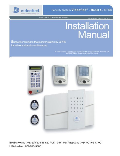
Subscriber linked to the monitor station by <strong>GPRS</strong><br />
for video and audio confirmation<br />
Document No. 2100-<strong>XL</strong> Jan. 2010<br />
EMEA Hotline : +33 (0)820 846 620 / UK : 0871 951 / Espagne : +34 90 166 77 00<br />
USA Hotline : 877-206-5800<br />
Security System Videofied ® - Model <strong>XL</strong> <strong>GPRS</strong><br />
Installation<br />
Manual<br />
<strong>XL</strong> <strong>GPRS</strong> means <strong>XL</strong>600<strong>GPRS</strong> for USA/Canada, <strong>XL</strong>700<strong>GPRS</strong> for Australia and<br />
<strong>XL</strong>200<strong>GPRS</strong> for Europe and rest of the world.
Contents<br />
Preamble......................................................................................1<br />
1. Preparation before programming ........................................... 2<br />
2. The golden rules .................................................................... 3<br />
3. Installation and programming ................................................3<br />
3.1 Initialize the panel .......................................................................3<br />
3.2 Record the keypad .....................................................................3<br />
3.3 Close the panel cover ...............................................................3<br />
4. End of installation ....................................................................7<br />
5. How to ... .................................................................................7<br />
5.1 Program the partial mode .......................................................7<br />
5.2 Delete the keypad .....................................................................8<br />
5.3 Register the keypad again on an <strong>XL</strong> panel .............................9<br />
5.4 Activate/disactivate the flashing green light symbol ...............9<br />
5.5 Open the cover of an installed <strong>XL</strong> panel ..................................9<br />
5.6 IP TMT Configuration ...............................................................9<br />
6. Detail of the menu : alarm codes .......................................... 10<br />
Signalisation des évènements par défaut ....................................10<br />
7. Table of <strong>GPRS</strong> codes... ....................................................... 11<br />
8. Numeric keypad... ................................................................. 12<br />
For further information, consult the installation manual :<br />
- Installation data sheet “Keypad”<br />
- Installation data sheet “Indoor MotionViewer TM ”<br />
- Installation data sheet “Outdoor MotionViewer TM ”<br />
- Installation data sheet “Motion detector”<br />
- Installation data sheet “Indoor siren”<br />
- Installation data sheet “Outdoor siren”<br />
- Installation data sheet “Remote control”<br />
- Installation data sheet “Silent Panic Keyfob”<br />
- Installation data sheet “Proximity Reader”<br />
- Installation data sheet “Motion detector”<br />
- Installation data sheet “Control relay”<br />
- Installation data sheet “Smoke detector”<br />
- Installation data sheet “Synoptics of the menus”<br />
Regulatory Information for USA<br />
FCC Part 15 Changes or modifications made to this equipment not expressly approved<br />
by RSI Video Technologies may void the FCC authorization to operate this equipment.<br />
FCC Part 15 Class B This equipment has been tested and found to comply with the<br />
limits for a Class B digital device, pursuant to part 15 of the FCC Rules. These limits<br />
are designed to provide reasonable protection against interference in a residential<br />
installation. This equipment generates, uses, and can radiate radio frequency<br />
energy and, if not installed and used in accordance with the instructions, may cause<br />
harmful interference to radio communications. However, there is no guarantee that<br />
interference will not occur in a particular installation.<br />
If this equipment does cause harmful interference to radio or television reception,<br />
which can be determined by turning the equipment off and on, the user is encouraged<br />
to try to correct the interference by one or more of the following measures:<br />
• Reorient or relocate the receiving antenna.<br />
• Increase the separation between the equipment and the receiver.<br />
• Connect the affected equipment and the panel receiver to separate AC power<br />
outlets, on different branch circuits.<br />
• Consult the dealer or an experienced radio/TV technician for help.<br />
This device complies with Part 15 of the FCC Rulesand with RS-210 of Industry<br />
Canada. Operation is subject to the following two conditions: (1) this device may not<br />
causeharmful interference, and (2) this device must accept any interferencereceived,<br />
including interference that may cause undesired operation.<br />
RF Exposure Warning: During operation, the user has to keep a minimum<br />
separation distance of 20 cm with the RF devices.<br />
For Canada:<br />
Le présent matériel est conforme aux spécifications techniques applicables<br />
d’Industrie Canada.<br />
L’utilisation de ce dispositif est autorisée seulement aux conditions suivantes :<br />
(1) il ne doit pas produire de brouillage et (2) l’utilisateur du dispositif doit être prêt à<br />
accepter tout brouillage radioélectrique reçu, même si ce brouillage est susceptible<br />
de compromettre le fonctionnement du dispositif.
Preamble<br />
The <strong>XL</strong> <strong>GPRS</strong> panel is specially designed for monitoring. It<br />
incorporates the main functions available in the VISIO panel<br />
range, including in particular:<br />
- Video verification<br />
- Radio range measurement<br />
- A 24/24 area<br />
- Automatically scheduled rearming (15 mins to 2 days)<br />
- The immediate processing of contacts opened during the<br />
arming.<br />
The <strong>XL</strong> panel is a comprehensive alarm panel which incorporates<br />
a <strong>GPRS</strong>/GSM transmitter, a 105dB siren, a microphone and a<br />
loud-speaker for audio verification, a touch-sensitive, back-lit<br />
keypad and a badge reader.<br />
Powered by 8 LR20 alkaline batteries and linked to the detectors<br />
via a secure radio frequency, the <strong>XL</strong> panel is entirely wireless<br />
and, for normal uses, will operate independently for 4 years.<br />
All Videofied devices are compatible with the <strong>XL</strong> (except for the<br />
SE250 external siren, replaced by the SE250, and the RAR100).<br />
• Installation principles<br />
In order to be configured and installed on-site, the <strong>XL</strong> requires<br />
the temporary use of a CMA-type external keypad.<br />
This can be removed from the system once the installation has<br />
been completed, tested and approved.<br />
• How it works<br />
Once armed, an intrusion or ‘panic’ call sets off its integrated<br />
siren and informs the remote surveillance centre of the events<br />
detected.<br />
The centre’s operator can then view the videos available and<br />
request further audio verification once or a number of times.<br />
The operator can thus switch as he wishes from an audio session<br />
to a video session (provided he is using FRONTEL SERVICES<br />
or FRONTEL RECEPTION BAY).<br />
The audio verification is carried out via a GSM call in full duplex.<br />
• Characteristics of the <strong>XL</strong> panel<br />
The <strong>XL</strong> panel incorporates:<br />
- A <strong>GPRS</strong>/GSM transmitter<br />
- A badge reader (2 tags included)<br />
- A 105dB siren<br />
- A microphone and loud-speaker for audio verification<br />
The <strong>XL</strong> panel is powered by 8 LR20 alkaline batteries.<br />
The <strong>XL</strong> panel supports:<br />
- 19 codes or badges (users and installer)<br />
- 19 devices of all types without distinction, including the CMA<br />
keypad for programming.<br />
Siren and loud-speaker Microphone<br />
Locking screw Badge reader<br />
Touch-sensitive<br />
keypad<br />
1
1. Preparation before programming<br />
On a piece of paper :<br />
• Name the 4 geographical zones<br />
A geographical zone corresponds to a surface where all the<br />
sensors are armed/disarmed together. A partial arming profile is<br />
a combination of geographical zones which are either armed or<br />
not. By using the examples below, you are going to meet most<br />
of the requirements.<br />
Area A magazine Area A person<br />
1 ENTRY DELAY 1 ENTRY DELAY<br />
2 MAGAZINE 2 RDC<br />
3 STOCK 3 FLOOR or OFFICE<br />
4 DISCOUNT 4 GARAGE<br />
(The1st geographical zone is inevitably delayed)<br />
• Name the devices<br />
Be as explicite as possible because in case of intrusion, it is this<br />
device’s name that will display on the keypad and transmit to the<br />
monitoring station. Example : CAM HALL ENTRANCE (for a<br />
camera at the entrance).<br />
• Allocate a geographical zone (from 1 to 4) to each<br />
device.<br />
2. The golden rules<br />
1 The area 1 is always delayed.<br />
2 Never place the panel near an electric switchboard :<br />
there is possible interference with the radio and <strong>GPRS</strong><br />
modem.<br />
3 Place the alarm panel at the most central location of the<br />
site to be protected (also garantees a better propagation of<br />
the radio).<br />
4 When there is typing error, use the to delete the<br />
incorrect character.<br />
5 Never record the same device twice without<br />
having first deleted the device off of the panel.<br />
6 Record a maximum of 19 devices of any kinds, without<br />
distinction (initial keypad included).<br />
7 Respect the installation height (under device) of<br />
PIR : 2m10 to 2m35, cameras MotionViewer : 2m10 to<br />
2m35 (ideally in an unobstructed angle)<br />
• Define the partial arming profiles (combinations of<br />
areas, see paragraph 5 and the partial programs on page 7).<br />
• Ask the end user to prepare his/her codes (18<br />
maximum access codes with 4 to 6 numbers per code).<br />
8 Respect the installation height (under device) of<br />
MotionViewer and PIR pet immune : 2m10.<br />
9 Installation height for external DCV cameras: 2m80 to 3m<br />
using the MB ball-and-socket joint (optional) and angling<br />
the camera at the target to be protected.<br />
10 If you are using a remote keypad, don’t install it at the<br />
11<br />
beginning of the installation<br />
Always clean the camera’s lens after installation<br />
(with a clean and dry piece of cloth, without pressing<br />
on the lens).<br />
12 To change from Capital to lower case, first press the ,<br />
then change from small letter/capital letter with and vice-<br />
versa.<br />
13 Be careful when opening and closing the panel cover (its<br />
components are fragile).
14<br />
2. The golden rules<br />
The keypad becomes inactive after 40 seconds of<br />
inactivity, in order to make the display to reappear,<br />
press on the [YES] key.<br />
15 Use alkaline batteries for the panel and for the interior and<br />
exterior sirens.<br />
3. Installation and programming<br />
Open the packaging box and take out the cardboard divider<br />
which serves as a gauge. Position it level against the attachment<br />
fitting, making sure the arrow is pointing upwards. Mark the 5<br />
points, remove the gauge and pierce the 4 attachment holes<br />
and the auto-protection hole. Attach the base. Insert the 8<br />
alkaline batteries in their lodgings, paying attention to the correct<br />
alignment of the positive and negative charges.<br />
Before removing the front side of the packaging box, insert the<br />
SIM card (voice/data or GSM/<strong>GPRS</strong>) as illustrated in figures 1<br />
and 2.<br />
Figure 1 Figure 2<br />
Alkaline batteries<br />
Power<br />
connection<br />
Power cable<br />
PROGRAM Button<br />
Videofied Security System Installation Manual<br />
16 The ITRA110/600 and DCVA200/600/700 (devices<br />
with pet immune) should never be placed<br />
in stairs, or near stairs. (Risk of untimely triggerings).<br />
Assemble the front side with the base by positioning the hinges<br />
on the base.<br />
Base<br />
3.1 Initialize the panel<br />
• Insert the power cable into the power connection (the panel<br />
emits a beep) and the keypad lights up and flashes.<br />
• Hold down the PROGRAM BUTTON on the panel for 10<br />
seconds untiil the keypad beeps again and lights up all the keys<br />
of the panel keypad.<br />
• Briefly press the PROGRAM BUTTON of the panel again to<br />
switch to keypad registration mode.<br />
3.2 Record the keypad (cf. Keypad installation<br />
manual)<br />
• Insert the 3 Lithium LS14500 batteries in the keypad.<br />
• Do not fix the keypad, it will help you in the recording and<br />
setting of the devices.<br />
• Simultaneously press on [CLR] and [ESC NO] buttons on<br />
the keypad, until the keypad’s indicator flashes and then release.<br />
3.3 Close the panel cover<br />
Hinges<br />
• Screw in the screw on the left of the box.<br />
3<br />
00
3. Installation and programming<br />
Display of the keypad<br />
KEYPAD 1<br />
RECORDED<br />
< - LANGUAGE - ><br />
ENGLISH<br />
RADIO RANGE<br />
TEST ?<br />
RADIO RANGE<br />
x/9<br />
RADIO RANGE<br />
9/9<br />
RADIO RANGE<br />
TEST ?<br />
ENTER THE<br />
INSTALLER CODE<br />
4 TO 6 DIGITS<br />
THEN YES<br />
INSTALLER CODE :<br />
CODE NAME :<br />
ADJUSTING<br />
TIME AND DATE<br />
DATE (Year) :<br />
00/ /<br />
CONNECTED TO<br />
MONITOR STATION?<br />
Wait<br />
Wait<br />
Actions and commentaries<br />
to select the language.<br />
Wait for 10s in order to obtain the first stable value<br />
Installer code + , then confirm : Code +<br />
Verify the range : A regular flashing or a<br />
value of 2/5 or better indicates a sufficient<br />
RF radio.<br />
In order to stop the test.<br />
Naming the code + (Becareful, some NAMES correspond to preprogramming<br />
of key accounts. (In case of incorrect setting, please contact<br />
your technical department).<br />
Wait<br />
Use direction arrows right or left to increase the<br />
numbers and the [YES] key to validate the value and move to the next.<br />
Do the same for the Month, the Day, the Time and the Minutes.
3. Installation and programming<br />
Videofied Security System Installation Manual<br />
Keypad Programming<br />
Display of the keypad Actions and commentaries<br />
ACCOUNT NUMBER :<br />
PERIODIC TEST<br />
PERIODIC TEST :<br />
24 HOURS<br />
TEST HOUR :<br />
00<br />
CODE/STATE<br />
MODIFICATION ?<br />
ENTER<br />
YOUR I.D. :<br />
NAME OR ADDRESS<br />
NAME OR ADDRESS<br />
ENTRY COMPLETE<br />
AREA<br />
CONFIGURATION<br />
AREA NAME 1 :<br />
EXIT DELAY :<br />
45 sec<br />
ENTRY DELAY :<br />
15 sec<br />
<strong>GPRS</strong><br />
PARAMETERS ?<br />
Enter the Transmittor code +<br />
Wait<br />
to change the period +<br />
to increase hours + , and do the same for minutes.<br />
or (to modify the event transmission status,and the on/off<br />
controls, refer to Chapter 6.Details on the alarm codes menu, page 10).<br />
Enter “name” or “address” + (Name of the client, informative and<br />
optional data only).<br />
Wait<br />
Enter the name of the geographic area 1 + .<br />
Do the same for other areas, turn to if need be to paragraph 1<br />
“1.Preparation before programming”, page 2.<br />
to modify the value +<br />
to modify the value +<br />
500
3. Installation and programming<br />
By default your <strong>GPRS</strong> panel has parameters of the ORANGE operator. It is necessary to modify the 3 parameters<br />
that characterise the connection to another operator (SFR or BOUYGUES, WYLESS, T-MOBILE, ATT...).<br />
Remark : <strong>GPRS</strong> Parameters is Case Sensitive ! (use the M/m key of the keypad to change Capital /Small letters).<br />
Be careful : Use arrows to change<br />
from one parameter to the other.<br />
Press on the [YES] key only when<br />
you want to modify a parameter!<br />
(The APN is given by your operator. These parameters are likely to change following the<br />
SIM card used. Ask your operator.)<br />
Display of the keypad Actions and commentaries<br />
APN CODE<br />
internet-entrepr<br />
USER NAME<br />
orange<br />
PASSWORD<br />
orange<br />
IP1 ADRESS<br />
0.0.0.0<br />
DOMAIN NAME 1<br />
PORT 1<br />
888<br />
<strong>GPRS</strong><br />
PARAMETERS ?<br />
<strong>GPRS</strong> LEVEL<br />
TEST IN PROGRESS<br />
END = YES<br />
<strong>GPRS</strong> LEVEL<br />
5/5<br />
PRESS PROGRAM<br />
BUTTON OF DEVICE<br />
ORANGE SFR BOUYGUES ........................<br />
APN internet-entreprise m2minternet a2bouygtel.com ........................<br />
USER orange Open field Open field ........................<br />
PASS orange Open field Open field ........................<br />
You are going to enter various parameters depending on which <strong>GPRS</strong><br />
operator’s SIM card you have.<br />
The first parameter is the APN code.<br />
By default, the standard public access parameters are those of Orange.<br />
Press [YES] to modify the value or the right arrow to move on to the next<br />
parameter.<br />
Second parameter: USERNAME<br />
Third parameter: PASSWORD<br />
The IP1 address or the domain name and Port 1 are provided by the<br />
monitoring station. Likewise for the IP2 address and the IP TMT address if<br />
applicable. Once the values have been established,<br />
Press the to return to the PARAMETRES <strong>GPRS</strong> menu.<br />
to exit the menu.<br />
Press the and wait for the reception level. Do not remove the SIM<br />
card during the test!<br />
Wait (this could last for 3 minutes) for the result of the test which can be :<br />
- a level between 1/5 and 5/5<br />
- an error code (in this case, call you technical support)<br />
It is not advisable to install a panel whose level is inferior to 3/5.<br />
Record your devices : (please refer to installation data sheets of each<br />
device).
4. End of installation<br />
You have recorded and fix all the devices, record the remote controls, then with the question :<br />
Display of the keypad Actions and commentaries<br />
ENTERING A NEW<br />
DEVICE ?<br />
OPERATION<br />
COMPLETED ?<br />
SYSTEM CHECK<br />
IN PROGRESS<br />
INSTALATION<br />
SUCCESSFUL !<br />
Videofied Security System Installation Manual<br />
(Close the cover of the panel)<br />
You can now close the <strong>XL</strong> panel, making sure you fully tighten the screw on the left-hand side.<br />
5. How to...<br />
5.1 Program partial mode<br />
With the direction arrows go to the menu<br />
CONFIGURATION (niv 4) -> ALARM MODES<br />
PROGRAMMABLES -> FULLY ARMED<br />
Then use the direction arrows to select the relevant arming<br />
mode and the [YES] key to modify it.<br />
There are three possible arming modes.<br />
NORMAL MODE is the general arming mode, set using a badge<br />
or with a user code and keys or .<br />
MODE SPECIAL1 is a partial mode activated by entering a user<br />
code and pressing the . This mode is also accessible on a<br />
CMA keypad via the and via an RC remote control via<br />
the .<br />
SPECIAL2 MODE is not accessible on the keypad of an <strong>XL</strong><br />
panel. It is available on a CMA keypad via the and via an<br />
RC remote control via the .<br />
For each arming mode, it is possible to specify how each of the<br />
4 zones will be armed and how the sound alert will be made.<br />
All that remains is to program the user<br />
codes, Partial arming modes and eventually<br />
the Intercom time (at 180 seconds).<br />
Areas : 1 2 3 4 Each time you press on the number<br />
of the area it modifies the correspondance.<br />
State : A A A A Situated below. Validation at the end, the<br />
[YES] key.<br />
A Armed Siren<br />
D Disarmed<br />
P<br />
E<br />
Perimeter<br />
(all the opening<br />
contacts)<br />
External (opening<br />
contacts protecting an<br />
exterior access)<br />
Delay<br />
beeps<br />
Silent<br />
Without<br />
siren<br />
Immediate triggering<br />
of all sirens<br />
Entry/Exit delay<br />
beeps, then triggering<br />
of the sirens<br />
Without siren<br />
without beeps<br />
Beeps on the<br />
keypad only<br />
PERIMETRIE MODE is not accessible on the <strong>XL</strong> keypad. It is<br />
only availble on the CMA deported keypad by + user<br />
code + [YES].<br />
700
00<br />
5. How to ...<br />
5.2 Delete the keypad<br />
Display of the keypad Actions and commentaries<br />
ACCESS LEVEL<br />
3<br />
ACCESS LEVEL<br />
LEVEL : 3 => 4<br />
Use the right arrow to increment the level to 4.<br />
BADGE OR CODE Enter the installer code +<br />
ACCESS LEVEL<br />
4<br />
CONFIGURATION<br />
BADGE OR CODE<br />
GENERAL<br />
PARAMETERS<br />
AREAS AND<br />
DEVICES<br />
DEVICES<br />
ADD A NEW<br />
DEVICE<br />
DEVICE<br />
CONFIGURATION<br />
Z1:KEYPAD<br />
KEYPAD 1<br />
DELATE<br />
KEYPAD<br />
< = = = = XX = = = = ><br />
Use the right arrow to go to the CONFIGURATION menu.<br />
Enter the installer code +<br />
Press the left arrow twice to go to the ZONES AND DEVICES menu.<br />
to go to the DEVICE CONFIGURATION menu.<br />
(If necessary, use the direction arrows to select the keypad).<br />
You can remove the keypad batteries.
5. How to ...<br />
5.3 Register again a CMA keypad on an <strong>XL</strong> panel<br />
without opening the cover<br />
Activate the touch-sensitive keypad by placing your hand over it.<br />
Enter in special mode by pressing for 3 seconds on the<br />
and the numerical keypad starts to flash.<br />
Type the code 000000 then to switch the <strong>XL</strong> panel<br />
in keypad registration mode. On the keypad:<br />
- Insert the 3 Lithium LS14500 batteries.<br />
- Simultaneously press [CLR] and [ESC NO] on the keypad<br />
untiil the indiicator light on the panel flashes and then release.<br />
5.4 Activate or disactivate the flashing green<br />
battery symbol<br />
It is possible to activate or disactivate the flashing green battery<br />
symbol.<br />
Bear in mind that when this symbol is activated, the product has<br />
less battery life and the batteries will have to be changed within<br />
4 years.<br />
Enter in special mode by pressing for 3 seconds on the<br />
and the numerical keypad starts to flash.<br />
Type the code 000100 then the digital keypad will<br />
remain illuminated while the green battery symbol starts to flash<br />
with the number 0 or 1 on the 7-segment digit.<br />
The number shown is an indication of the display configuration<br />
for the battery symbol (0 for disactivated, 1 for activated).<br />
Videofied Security System Installation Manual<br />
Display of the keypad Actions<br />
KEYPAD 1<br />
RECORDED<br />
INSTALLATION CODE Enter the installer code +<br />
5.5 Open the cover of an installed <strong>XL</strong> panel<br />
Unscrew the screw on the left-hand side of the panel and<br />
separate the panel of the base.<br />
5.6 IP TMT Configuration<br />
You need a computer connected to the network IP, configured<br />
either on a fixed address IP with the opened port 888 is needed,<br />
or on a name of domain with the opened port 888.<br />
About the programming of the panel, it is necessary either to<br />
inform on the IP TMT your fixed IP, or on DOMAIN NAME your<br />
domain name.<br />
The computer connected on your network has to have the<br />
software Fontel TMT installed and parametrized.<br />
The connection by seizing 999999 + [OK] on the panel <strong>XL</strong>,<br />
either on the keypad CMA (if it is on the site).<br />
In Frontel TMT make: File / open, a window opens with the<br />
account N ° (code transmitter).<br />
Click above, validate the request of remote maintenance<br />
by clicking on OK, then to make an import to get back the<br />
programming of the site.<br />
900
6. Details of the menu : ALARM CODE<br />
Signalling events by default (except if you are<br />
using pre programming)<br />
By default these events are transmited:<br />
DEVICE (intrusions)<br />
ALERT (button)<br />
TAMPER<br />
PERIODIC TEST<br />
There are the 3 transmission<br />
states:<br />
ALARM, which can be heard :<br />
when it appears<br />
ALARM / END, which can be<br />
heard : when it appears and disappears<br />
NOT TRANSMITTED<br />
Examples :<br />
INITIALIZATION<br />
By default are not transmited:<br />
PANEL BATTERIES (low panel batteries)<br />
AC POWER (panel power off)<br />
PHONELINE FAULT (telephone)<br />
DEVICE BATT. (low batteries devices)<br />
RADIO JAMMING (radio jamming)<br />
SUPERVISION (default supervision)<br />
WRONG CODES (when entering 5 false codes/badges)<br />
DURESS CODE (panic button)<br />
ALARM MEMORY (old memory overwritten)<br />
ARM/DISARM (open/close)<br />
- If one wishes to recall events of ARMING/DISARMING (operate/stop), you will have to modify the<br />
configuration of events ARMING/DISARMING to ALARM / END.<br />
- If you wish to recall the false codes information, you will have to modify the configuration of events<br />
WRONG CODES on the state ALARM.<br />
How to modify the transmission state of events?<br />
2 possible solutions:<br />
• At installation, just after having validated the hour of the cyclic test, the keypad requests :<br />
CODE/STATE<br />
MODIFICATION ?<br />
• After the initial installation, by using the keypad :<br />
With direction arrows go to the menu CONFIGURATION (level 4) -> CONFIGURATION MONITOR. STATION<br />
-> ALARM CODES -> TRANS. STATE MODIFICATION<br />
Then:<br />
In all cases, be sure to check that the configuration of your <strong>XL</strong><br />
system is suitable for your needs.<br />
Press on the to access the menu TRANS. STATE MODIFICATION<br />
With direction arrows Select the event to transmit, make then modify the transmission state with arrows<br />
and revalidate with the [YES] key. Renew the operation for each event which you wish to modify the transmission regulations.
7. Table of <strong>GPRS</strong> error code correspondances<br />
During the <strong>GPRS</strong> level test, if there is an error an associated code appears in place of the the <strong>GPRS</strong> level.<br />
<strong>GPRS</strong> LEVEL :<br />
ERROR XXX<br />
Table of correspondance error codes<br />
915 MHz codes<br />
Start the test again after first error.<br />
Codes Errors<br />
In case of <strong>GPRS</strong> error, we recommend you continue installation by<br />
recording of detectors and devices and then come back to the <strong>GPRS</strong> level<br />
test.<br />
03 ou 04 No network coverage or no SIM card <strong>GPRS</strong> data<br />
010 SIM non inserted<br />
011<br />
Code PIN necessary<br />
-> The PIN code must be disactivated<br />
012 Code PUK necessary, SIM card blocked<br />
013 Default SIM card<br />
014 SIM card busy<br />
015 Error on SIM<br />
016 Incorrect password<br />
017<br />
SIM PIN2 necessary<br />
-> The PIN code must be disactivated<br />
018 SIM PUK2 necessary<br />
022 SIM not found<br />
030 No network coverage or no SIM card <strong>GPRS</strong> data<br />
040 : 047<br />
149<br />
107<br />
!!! The PIN code of the SIM cards must either be disactivated or be 0000 !!!<br />
SIM card non inappropriate or blocked<br />
-> Unlock with PUK code<br />
Authentification error<br />
-> Incorrect Network problem or parameters (APN, USER, ...)<br />
Service data <strong>GPRS</strong> non authorised<br />
-> SIM card unsuitable<br />
Codes Errors<br />
043 Typographical error in the APN Code username or password<br />
003 SIM card not detected/no inserted<br />
132 SIM card not activated<br />
030 No <strong>GPRS</strong> signal<br />
11
00<br />
8. Numeric Keypad<br />
Symbols Explanations<br />
D<br />
P<br />
• When the indicator light is green: indicates that all the batteries (panel + peripheral) are OK<br />
• When the indicator light is red: indicates that there is a battery fault either on the panel or on<br />
a peripheral device (the N° will be indicated on the display)<br />
• During arming: signals the detection of a peripheral device in a zone not on a time setting<br />
• Not armed: signals the auto-protection of a peripheral device (the N° will be indicated on<br />
the display)<br />
Used in order to identify:<br />
• N° of the peripheral device (0 for the panel and 1 to 19 for the peripheral devices) in the vent<br />
of auto-protection, intrusion, low battery, etc.<br />
• Incorrect authentification (‘C’ for wrong code)<br />
Indicates that there has been an intrusion<br />
Indicates any other fault (radio interference, ect.)<br />
Symbols Explanations<br />
D Used to disarm the system (after entering the code)<br />
P<br />
• Enables arming in partial mode (after entering the code)<br />
• Flashes when the system is partially armed<br />
• Enables arming in total mode (after entering the code)<br />
• Flashes when the system is totally armed<br />
Enables arming in total mode (after entering the code)<br />
Symbols Explanations<br />
D Key to be held down for 3 seconds to activate panic buttons<br />
P Once it lights up, pressing this key will send a police call through to the monitoring station<br />
Once it lights up, pressing this key will send an emergency call through to the operators<br />
Once it lights up, pressing this key will send an emergency call through to the operators<br />
This key allows you to cancel the activation of the panic buttons<br />
Symbols Explanations<br />
à D Keys for entering user codes<br />
P Key for confirming code<br />
Delete key in case off error<br />
Using the numeric keypad: to conserve the batteries, the numerical keypad automatically turns off after a few seconds of not being used. Before entering<br />
the code, you need to reactivate it. To do so, place your hand flat over the numeric keypad, it will light up and then you can use it.<br />
EMEA SALES<br />
23, avenue du Général Leclerc<br />
92340 BOURG-LA-REINE<br />
FRANCE<br />
Hot line : +33 (0)820 846 620<br />
Fax : +33 (0)3 90 20 66 36<br />
www.videofied.com<br />
© 2009 RSI Video Technologies <strong>Videofied®</strong> is a Registered Trademark of RSI Video Technologies.<br />
Specifications subject to change without notice.<br />
North American Headquarters<br />
4455 White Bear Parkway, Suite 700<br />
White Bear Lake, MN 55110<br />
USA<br />
Hot Line : 877-206-5800<br />
Fax : 651-762-4693
- Installation data sheet “Keypad”<br />
- Installation data sheet “Indoor MotionViewer”<br />
- Installation data sheet “Outdoor MotionViewer”<br />
- Installation data sheet “Motion detector”<br />
- Installation data sheet “Indoor siren”<br />
- Installation data sheet “Outdoor siren”<br />
- Installation data sheet “Remote control”<br />
Security System Videofied ® - <strong>XL</strong> <strong>GPRS</strong><br />
Made by RSI VIDEO TECHNOLOGIES Janv. 2010<br />
Installation<br />
data sheet<br />
- Installation data sheet “Silent Panic Keyfob”<br />
- Installation data sheet “Proximity Reader”<br />
- Installation data sheet “Motion detector”<br />
- Installation data sheet “Control relay”<br />
- Installation data sheet “Smoke detector”<br />
- Installation data sheet “Synoptics of the menus”<br />
<strong>XL</strong> <strong>GPRS</strong> means <strong>XL</strong>600<strong>GPRS</strong> for USA/Canada, <strong>XL</strong>700<strong>GPRS</strong> for<br />
Australia and <strong>XL</strong>200<strong>GPRS</strong> for Europe and rest of the world.<br />
EMEA Hotline : +33 (0)820 846 620 / UK : 0871 951 / Espagne : +34 90 166 77 00<br />
USA Hotline : 877-206-5800
Indicator LED<br />
Special Arming<br />
Mode 1 and<br />
Special Arming<br />
Mode 2<br />
Direction<br />
arrows<br />
Capital / Small<br />
letter<br />
Panic button<br />
1. Arming and Disarming<br />
The keypad becomes inactive after 30 seconds of inactivity. To<br />
revive the keypad you can press any key on the keypad. The<br />
best button to press is the [YES] key because it will not trigger<br />
an action.<br />
Recording of a keypad<br />
The alarm panel must be put in "Recording device<br />
mode", and the keypad must display “PRESS<br />
PROGRAM BUTTON OF DEVICE”.<br />
Insert the 3 batteries Lithium LS14500 (the<br />
3 batteries are inserted in the same<br />
direction)<br />
Press simultaneously on [CLR] and<br />
[ESC NO] of the keypad until the indicator<br />
of the keypad flashes and release<br />
(possibility of testing the RF range).<br />
Arming Fully Armed Special Mode 1 or 2 Perimeter<br />
Keys of the<br />
Keypad<br />
Code + + or + Code + + + Code +<br />
Disarming Fully Armed Special Mode 1 or 2 Perimeter<br />
Keys of the<br />
Keypad<br />
Made by RSI VIDEO TECHNOLOGIES<br />
Programming<br />
Buttons<br />
I N S T A L L A T I O N D A T A S H E E T<br />
Display : 2 lines with 16 characters<br />
Perimeter<br />
To change from one arming mode to another, you have to<br />
to fully disarm the system.<br />
+ Code + + Code + + Code +<br />
CMA means CMA600 for USA/Canada, CMA700 for Australia/<br />
Singapore and CMA200 for Europe and rest of the world. www.videofied.com<br />
1<br />
2<br />
Keypad CMA
2. Obtaining special characters<br />
Key<br />
1 st press<br />
2 th press<br />
3 th press<br />
4 th press<br />
5 th press<br />
6 th press<br />
7 th press<br />
8 th press<br />
9 th press<br />
10 th press<br />
1 “space” . , ‘ ? ! ; : # 1<br />
0 - + = / ¥ _ < > ( ) 0<br />
@ @ $ % & * #<br />
> REM : The other keys function as in writing SMS with a<br />
cellular phone.<br />
3. Initiating Panic Alerts<br />
3.1 Red Button of the keypad<br />
Panic alert : immediately triggers on all sirens.<br />
Key order to activate/disactivate the function :<br />
11 th press<br />
With direction arrows go to menu:<br />
PROGRAMMABLE FEATURES -> PANIC BUTTON<br />
ENABLED. Validate with the [YES] key. Use direction arrows to<br />
modify the state.Validate with the [YES] key.<br />
Enter the installer code if need be.<br />
3.2 Silent Panic alert<br />
On the keypad : Code under constraint (or under threat) : User<br />
code + 1, example : (2999 -> 3000)<br />
On the remote control : Press 2 seconds on the key<br />
(acquisition bip for 2 seconds)<br />
3.3 Audible Panic Alert<br />
Keypad CMA<br />
On the keypad : Code under constraint (or under threat) : User<br />
code + 2, example : (2999 -> 3001)<br />
On the remote control : Press 2 seconds on the key<br />
(acquisition bip for 2 seconds)<br />
Remark : If the red button of the keypad is deactivated, the alert<br />
sound on the remote control will not function, but on the keypad<br />
will still display that the panic has been pressed and will require<br />
a code + [YES].<br />
4. I have a problem, what should I do?<br />
4.1 My first keypad does not record on the panel<br />
Have you pressed on the PROGRAM BUTTON of the panel<br />
before trying to record on the keypad?<br />
4.2 Retrieve a keypad deleted by error<br />
Remove the keypad's batteries.<br />
Press the PROGRAM BUTTON of the panel for one second<br />
(cover closed), (the indicator flashes once). Put back the batteries<br />
and initialize the keypad by simultaneously pressing on the [CLR]<br />
and [ESC NO] key unitl the indicator of the latter flashes and then<br />
release. It will then require you to enter the installer code (do so<br />
and validate with the [YES]) key, then the keypad is recovered.<br />
4.3 How to fix a faulty keypad, without re-program-<br />
ming the site<br />
Press on the PROGRAM BUTTON of the panel for one second<br />
(cover closed), the indicator flashes once.<br />
Put the batteries in the new keypad.<br />
Press the [CLR] and [ESC/NO] keys simultaneously unit its<br />
indicator flashes and then release. The keypad records.<br />
Key in the installer code again on the keypad's demand.<br />
Possibility of testing RF radio range and out of this menu and the<br />
new keypad is operational.<br />
Proceed in carrying out in limited time of 15 seconds and renew<br />
the operation if need be.<br />
(Do not forget to delete the faulty keypad of the programming,<br />
otherwise there will be a RF Supervision of radio loss…)<br />
5. Add a second keypad<br />
It is possible to add several keypads on the same site. During<br />
the recording of a new keypad, it is possible to allocate to a<br />
geographical zone other than zone 1, but in this case the new<br />
chosen zone shall also be delayed.<br />
EMEA SALES<br />
23, avenue du Général Leclerc<br />
92340 BOURG-LA-REINE<br />
FRANCE<br />
Hot line : +33 (0)820 846 620 / UK : 0871 951<br />
Fax : +33 (0)3 90 20 66 36<br />
I N S T A L L A T I O N I N S T R U C T I O N<br />
CMA means CMA600 for USA/Canada, CMA700 for Australia/<br />
Singapore and CMA200 for Europe and rest of the world.<br />
www.videofied.com<br />
© 2009 RSI Video Technologies <strong>Videofied®</strong> is a Registered Trademark of RSI Video Technologies.<br />
Specifications subject to change without notice.<br />
North American Headquarter<br />
4455 White Bear Parkway, Suite 700<br />
White Bear Lake, MN 55110<br />
USA<br />
Hot line : 877-206-5800<br />
Fax : 651-762-4693
The detector must be fixed with<br />
a screw, one of which must be<br />
positioned in the tear-off zone<br />
INIT Button<br />
Recording of the detector<br />
The alarm panel must be placed in “Recording device”,<br />
mode then and the keypad must display“PRESS<br />
PROGRAM BUTTON OF DEVICE”.<br />
1<br />
2<br />
3<br />
Insert the 3 Lithium batteries LS14500 (in the same<br />
direction).<br />
Press the PROGRAM BUTTON of the detector,<br />
release as soon as the indicator flashes.<br />
I n d i c a t o r<br />
LED<br />
With the aid of the keypad, continue recording by<br />
running the Radio Range Test and allocating an<br />
area....<br />
Always place the camera on an unobstructed angle.<br />
Made by RSI VIDEO TECHNOLOGIES<br />
Installation height of the pet immune camera :<br />
2m10 (6 1/2’) to the bottom of the camera<br />
Infrared<br />
illuminators<br />
for night<br />
vision.<br />
Objective of<br />
the camera<br />
Camera<br />
DCV200<br />
DCV600<br />
DCV700<br />
DCVA200<br />
DCVA600<br />
DCVA700<br />
> Possibility of testing the RF range.<br />
Pet immune Installation height<br />
NONE<br />
YES 18 KG (40lbs)<br />
> Possibility of testing the detection cover range.<br />
From 2m10 (6 1/2’) to<br />
2m30 (7 1/2’) to the<br />
bottom of the camera<br />
Must imperatively be<br />
2m10 (6 1/2’) to the<br />
bottom of the camera<br />
* This indicator will no longer flash from then on except at<br />
opening or during a detection test.<br />
EMEA SALES<br />
23, avenue du Général Leclerc<br />
92340 BOURG-LA-REINE<br />
FRANCE<br />
Hot line : +33 (0)820 846 620 / UK : 0871 951<br />
Fax : +33 (0)3 90 20 66 36<br />
I N S T A L L A T I O N D A T A S H E E T<br />
DCV means DCV600 for USA/Canada, DCV700 for Australia/Singapore<br />
and DCV200 for Europe and rest of the world.<br />
www.videofied.com<br />
© 2009 RSI Video Technologies <strong>Videofied®</strong> is a Registered Trademark of RSI Video Technologies.<br />
Specifications subject to change without notice.<br />
Indoor MotionViewer<br />
DCV<br />
North American Headquarter<br />
4455 White Bear Parkway, Suite 700<br />
White Bear Lake, MN 55110<br />
USA<br />
Hot line : 877-206-5800<br />
Fax : 651-762-4693
The outdoor MotionViewer detector DCV250/DCV650/<br />
DCV750 is integrated with filters and analytical levels which<br />
enables it from untimely triggering on with the presence of<br />
small animals : rabbits, cats, birds.... However, dogs, foxes<br />
and wild boars can be detected.<br />
It is highly recommended to use a camera head kit (no Kodak<br />
screw) or our MB100 camera kit to fix the camera, indeed,<br />
if you bore a hole in the lower stand of the camera, its<br />
waterproofness will be lost...<br />
Composition of the MB100 kit<br />
- Base stand with screw cover.<br />
- A camera head enabling a 360° orientation of the camera<br />
with a wing screw (or Allen screw supplied with its key).<br />
- Two extension cords - 5 cm each. Camera fixing screw<br />
(diameter 6.35 mm - 20 threads per inch).<br />
Indicator LED<br />
Camera<br />
Infrared LED for night vision<br />
DCV means DCV650 for USA/Canada, DCV750 for Australia/Singapore<br />
and DCV250 for Europe and rest of the world.<br />
Made by RSI VIDEO TECHNOLOGIES<br />
I N S T A L L A T I O N D A T A S H E E T<br />
Installation height of the outdoor camera :<br />
2m80 to 3m (9’ to 9 1/2’) to the bottom of the camera<br />
Base<br />
Extention<br />
5 cm (2 1/2<br />
inches)<br />
Base<br />
Screw cover<br />
for the base<br />
Outdoor MotionViewer<br />
DCV<br />
Clamping<br />
ring<br />
Screw + Allen<br />
key Wing screw<br />
Clamping screw for camera<br />
Ball pivot<br />
360°
Outdoor MotionViewer DCV<br />
Recording of the detector<br />
The alarm panel must be put in "Recording device<br />
mode", and the keypad must display“PRESS<br />
PROGRAM BUTTON OF DEVICE”.<br />
1<br />
2<br />
3<br />
4<br />
5<br />
6<br />
7<br />
8<br />
9<br />
10<br />
11<br />
Insert the 3 Lithium batteries LS14500 (in the same<br />
directions).<br />
Press the PROGRAM BUTTON of the camera<br />
detector, release as soon as the indicator flashes.<br />
Carefully place the block camera on its base<br />
and screw down the 4 clamping screws.<br />
Fix the base of the ball and socket head on a desired<br />
height and place (while respecting fixing height.<br />
Place the screw cover on top and screw down the<br />
ball pivot.<br />
If need be, use extentions then screw them down<br />
to the camera detector on the top of the ball and<br />
socket head (or extentions) and screw down<br />
the ring of the ball and socket head in order<br />
guarantee adequate fixing.<br />
Finally, direct the camera as required and tighten<br />
with wing screw or Allen screw (to be used instead of<br />
the wing screw).<br />
Test the RF range (RSSI level at 20 seconds).<br />
Allocate an area (with direction arrows of the keypad)<br />
and validate with the [YES] key.<br />
Name the device.<br />
Test the detection coverage area.<br />
> Possibility of testing RF cover (minimum radio level at 20).<br />
> Possibility of testing the detection cover range.<br />
* This indicator will no longer flash from then on except at<br />
opening, arming or during a detection test.<br />
DCV means DCV650 for USA/Canada, DCV750 for Australia/Singapore<br />
and DCV250 for Europe and rest of the world.<br />
I N S T A L L A T I O N D A T A S H E E T<br />
Location of the ball pivot,<br />
camera fixing screw<br />
Self protection<br />
of the camera<br />
EMEA SALES<br />
23, avenue du Général Leclerc<br />
92340 BOURG-LA-REINE<br />
FRANCE<br />
Hot line : +33 (0)820 846 620 / UK : 0871 951<br />
Fax : +33 (0)3 90 20 66 36<br />
www.videofied.com<br />
Back wall<br />
Camera block<br />
© 2009 RSI Video Technologies <strong>Videofied®</strong> is a Registered Trademark of RSI Video Technologies.<br />
Specifications subject to change without notice.<br />
Program Button<br />
North American Headquarter<br />
4455 White Bear Parkway, Suite 700<br />
White Bear Lake, MN 55110<br />
USA<br />
Hot line : 877-206-5800<br />
Fax : 651-762-4693
The detector<br />
must be fixed<br />
with a screw, one<br />
of which must be<br />
positioned in the<br />
tear-off zone<br />
Recording of the detector<br />
The alarm panel must be put in "Recording device<br />
mode", and the keypad must display“PRESS<br />
PROGRAM BUTTON OF DEVICE”.<br />
1<br />
2<br />
3<br />
Insert the Lithium LS14500 Battery.<br />
Press on the PROGRAM button of the detector,<br />
release as soon as the indicator flashes.<br />
With the aid of the keypad, continue recording by<br />
allocating an area name ...<br />
Indicator<br />
LED<br />
PROGRAM<br />
Button<br />
Height of the pet animal detectors: must be 2m10 (6<br />
1/2’) minimum.<br />
Always place the camera on an unobstructed angle.<br />
Made by RSI VIDEO TECHNOLOGIES<br />
Installtion height of pet immune PIR:<br />
2m10 (6 1/2’) to the bottom of the device<br />
ITR110<br />
ITR600<br />
ITRA110<br />
ITRA600<br />
> Possibility of testing the RF range.<br />
Pet immune Installation height<br />
NONE<br />
YES 18 KG (40lbs)<br />
> Possibility of testing the detection cover range.<br />
From 2m10 (6 1/2’) to<br />
2m30 (7 1/2) to the<br />
bottom of the camera<br />
Must be 2m10 (6<br />
1/2’) minimum to the<br />
bottom of the camera<br />
* This indicator will no longer flash from then on except at<br />
opening, arming or during a detection test.<br />
EMEA SALES<br />
23, avenue du Général Leclerc<br />
92340 BOURG-LA-REINE<br />
FRANCE<br />
Hot line : +33 (0)820 846 620 / UK : 0871 951<br />
Fax : +33 (0)3 90 20 66 36<br />
I N S T A L L A T I O N D A T A S H E E T<br />
ITR & ITRA means ITR600 & ITRA600 for USA/Canada and ITR110 &<br />
ITRA110 for Europe and rest of the world.<br />
www.videofied.com<br />
© 2009 RSI Video Technologies <strong>Videofied®</strong> is a Registered Trademark of RSI Video Technologies.<br />
Specifications subject to change without notice.<br />
Movement detector<br />
ITR & ITRA<br />
North American Headquarter<br />
4455 White Bear Parkway, Suite 700<br />
White Bear Lake, MN 55110<br />
USA<br />
Hot line : 877-206-5800<br />
Fax : 651-762-4693
Alkaline<br />
batteries<br />
PROGRAM<br />
Button<br />
Indicator LED<br />
Made by RSI VIDEO TECHNOLOGIES<br />
USE ALKALINE BATTERIES ONLY<br />
Recording the interior siren<br />
The alarm panel must be put in "Recording device<br />
mode", and the keypad must display“PRESS<br />
PROGRAM BUTTON OF DEVICE”.<br />
1<br />
2<br />
Insert the 4 batteries Alkaline LR20.<br />
Press carefully the PROGRAM Button of the siren,<br />
release as soon as the indicator flashes.<br />
-> Possibility of testing the RF range.<br />
> Remark : The addition of an interior siren will inhibite the<br />
panel siren, which can be reactivated.<br />
To do this then go to the menu : CONFIGURATION -> AREAS<br />
AND DEVICES-> SIREN PANEL + [YES].<br />
Chose the authorized state.<br />
> Remark : When a interior siren is added, the entry/exit beeps<br />
are automatically added into it.<br />
It is possible to remove it in the menu : CONFIGURATION -><br />
AREAS AND DEVICES -> DELAY BEEPS + [YES].<br />
Chose the inhibited state.<br />
EMEA SALES<br />
23, avenue du Général Leclerc<br />
92340 BOURG-LA-REINE<br />
FRANCE<br />
Hot line : +33 (0)820 846 620 / UK : 0871 951<br />
Fax : +33 (0)3 90 20 66 36<br />
I N S T A L L A T I O N D A T A S H E E T<br />
SE means SE600 for USA/Canada, SE700 for Australia/Singapore and<br />
SE200 for Europe and rest of the world.<br />
www.videofied.com<br />
© 2009 RSI Video Technologies <strong>Videofied®</strong> is a Registered Trademark of RSI Video Technologies.<br />
Specifications subject to change without notice.<br />
Indoor Siren SE<br />
North American Headquarter<br />
4455 White Bear Parkway, Suite 700<br />
White Bear Lake, MN 55110<br />
USA<br />
Hot line : 877-206-5800<br />
Fax : 651-762-4693
Strobe<br />
positioned<br />
downwards<br />
Alkaline<br />
batteries<br />
PROGRAM<br />
Button<br />
Indicator LED<br />
Made by RSI VIDEO TECHNOLOGIES<br />
ALKALINE BATTERIES ONLY<br />
The siren must be positioned downwards.<br />
Recording of the exterior siren<br />
The alarm panel must be put in "Recording device<br />
mode", and the keypad must display“PRESS<br />
PROGRAM BUTTON OF DEVICE”.<br />
1<br />
2<br />
3<br />
Insert the 4 batteries Alkaline LR20.<br />
Press carefully the PROGRAM Button of the siren,<br />
release as soon as the indicator flashes.<br />
To the question REMOTE CONTROLLED,<br />
answer : [ESC/NO].<br />
-> Possibility of testing the RF range.<br />
Do not forget to connect the strobe's cable !!!<br />
Reminder : Outdoor siren : waterproof : IP432.<br />
EMEA SALES<br />
23, avenue du Général Leclerc<br />
92340 BOURG-LA-REINE<br />
FRANCE<br />
Hot line : +33 (0)820 846 620 / UK : 0871 951<br />
Fax : +33 (0)3 90 20 66 36<br />
I N S T A L L A T I O N D A T A S H E E T<br />
www.videofied.com<br />
© 2009 RSI Video Technologies <strong>Videofied®</strong> is a Registered Trademark of RSI Video Technologies.<br />
Specifications subject to change without notice.<br />
Outdoor siren SE<br />
SE means SE650 for USA/Canada, SE750 for Australia/Singapore and<br />
SE250 for Europe and rest of the world.<br />
North American Headquarter<br />
4455 White Bear Parkway, Suite 700<br />
White Bear Lake, MN 55110<br />
USA<br />
Hot line : 877-206-5800<br />
Fax : 651-762-4693
Press<br />
simultaneously for 5 seconds<br />
ON and OFF<br />
Full Arming<br />
Special Mode 1<br />
Audible<br />
Panic Alert<br />
by pressing 2<br />
seconds<br />
Reminder of the controls<br />
Made by RSI VIDEO TECHNOLOGIES<br />
RC means RC600 for<br />
USA/Canada, RC700 for<br />
Australia/Singapore and<br />
RC200 for Europe and<br />
rest of the world.<br />
Disarming<br />
Special Mode 2<br />
Silent panic<br />
alert by<br />
pressing 2<br />
seconds<br />
Recording of the remote control<br />
The alarm panel must be put in "Recording device mode", and<br />
the keypad must display“PRESS PROGRAM BUTTON OF<br />
DEVICE”.<br />
Press 5 seconds simultaneously on the ON and OFF keys of<br />
the remote control.<br />
When released the remote control emits bips and then<br />
records.<br />
If the remote control does not record, first verify if the keypad<br />
displays well :<br />
PRESS PROGRAM<br />
BUTTON OF DEVICE<br />
then simultaneously press once more on the ON and OFF of<br />
the remote control for 5 seconds (by firmly pressing on the<br />
keys). If the remote control does not record then carry out the<br />
operation once again but this time for 12 seconds.<br />
> Fonctioning<br />
During the arming (Full and Special modes) and disarmings, it is<br />
necessary to press on the desired key and release very quickly<br />
with the first beep. Do not press and hold on the key !<br />
On the other hand, if the desired control is accepted by the panel,<br />
the remote control will emit 2 beeps otherwise one and you will<br />
have to retry ...<br />
For alerts (long pressing for 2 seconds on the partials), from the<br />
begining of the pressing the remote control emits a beep, then<br />
again at the end 2 seconds indicating that the duration of pressure<br />
is sufficient, you can then release the key. If the panel recieved<br />
the frame of alert, the remote control emits 2 beeps, indicating a<br />
good functioning condition. Otherwise the remote control will only<br />
emit one sound, then renew the operation.<br />
> Remark : This remote control has only one battery (lithium)<br />
solded with an autonomy and a standard use of 10 years. Do not<br />
try to open the remote control.<br />
According to the version of the Videofied panel, if we use the remote control to arm the system, it transfers the time out beeps (which will<br />
enable you to know if the contact of the site remained open : 4 seconds long beep on the remote control, if everything is ok, the remote control<br />
transfers the beeps normally). It is not necessary to wait for the end of the beep to leave the site (for example, if arming is carried out from a<br />
car, the beeps will automatically stop at the end of 45 seconds).<br />
EMEA SALES<br />
23, avenue du Général Leclerc<br />
92340 BOURG-LA-REINE<br />
FRANCE<br />
Hot line : +33 (0)820 846 620 / UK : 0871 951<br />
Fax : +33 (0)3 90 20 66 36<br />
www.videofied.com<br />
I N S T A L L A T I O N D A T A S H E E T<br />
© 2009 RSI Video Technologies <strong>Videofied®</strong> is a Registered Trademark of RSI Video Technologies.<br />
Specifications subject to change without notice.<br />
4 buttons remote control<br />
RC<br />
North American Headquarter<br />
4455 White Bear Parkway, Suite 700<br />
White Bear Lake, MN 55110<br />
USA<br />
Hot line : 877-206-5800<br />
Fax : 651-762-4693
Functioning<br />
All button :<br />
Silent Panic call<br />
(duress code event)<br />
For silent alerts press and hold 2 seconds on one of the 4 keys.<br />
From the begining of the pressing, the remote control emits a<br />
beep, then again at the end of the 2 seconds indicating that the<br />
duration of pressure is sufficient, you can then release the key.<br />
If the panel received the alert, the remote control emits 2 beeps,<br />
indicating a good functioning condition.<br />
Otherwise the remote control will only emit one sound, then<br />
renew the operation.<br />
Once the alert from the keyfob is recieved, the panel will forward<br />
it to monitoring station<br />
> Remark : This remote control has only one battery (lithium)<br />
solded to the autonomy and a standard use of 10 years.<br />
Do not try to open the remote control.<br />
Made by RSI VIDEO TECHNOLOGIES<br />
RC P means RC600P for<br />
USA/Canada, RC700P<br />
for Australia/Singapore<br />
and RC200P for Europe<br />
and rest of the world.<br />
Recording of the remote control<br />
The alarm panel must be put in "Recording device mode", and<br />
the keypad must display“PRESS PROGRAM BUTTON OF<br />
DEVICE”.<br />
Press 7 seconds simultaneously on the height keys of the<br />
remote control.<br />
When released the remote control emits bips and then<br />
records.<br />
If the remote control does not record, first verify if the keypad<br />
displays :<br />
PRESS PROGRAM<br />
BUTTON OF DEVICE<br />
then simultaneously press once more on the height keys of<br />
the remote control for 7 seconds (by firmly pressing on the<br />
keys). If the remote control does not record then carry out the<br />
operation once again but this time for 12 seconds.<br />
Be sure the panel is well set-up to manage the silent alert.<br />
The transmission status of the DURESS CODE event must be set to<br />
ALARM.<br />
EMEA SALES<br />
23, avenue du Général Leclerc<br />
92340 BOURG-LA-REINE<br />
FRANCE<br />
Hot line : +33 (0)820 846 620 / UK : 0871 951<br />
Fax : +33 (0)3 90 20 66 36<br />
www.videofied.com<br />
I N S T A L L A T I O N D A T A S H E E T<br />
© 2009 RSI Video Technologies <strong>Videofied®</strong> is a Registered Trademark of RSI Video Technologies.<br />
Specifications subject to change without notice.<br />
Silent Panic Keyfob<br />
RC P<br />
North American Headquarter<br />
4455 White Bear Parkway, Suite 700<br />
White Bear Lake, MN 55110<br />
USA<br />
Hot line : 877-206-5800<br />
Fax : 651-762-4693
Description<br />
The proximity reader can be placed in the interior or exterior<br />
because the electronic card is weather proof. This device is used<br />
for arming and disarming a VIDEOFIED ® system. The recording<br />
of the badge reader in a recording area makes that area and all<br />
devices in that area subject to the entry and exit delays.<br />
Characteristics<br />
It is possible to record 19 badges, each badge takes the position<br />
of a user code. Example : 5 badges recorded + 4 keypad user<br />
codes, remaining 10 codes and/or badges available.<br />
In order to read the badge, the badge must be placed in contact<br />
with the reader surface for approximately half a second (a beep<br />
is emitted when the badge is read).<br />
Remark : The total starting up and stopping are handled by the<br />
badge readers ...<br />
Mocate “TOP-HIGH”<br />
Base to be fixed<br />
Fixing point of the protection against<br />
opening and pulling out<br />
2 screws for fixing<br />
Magnet for<br />
tamper open on<br />
the reader<br />
Wall tamper<br />
punch out<br />
BR means BR650 for USA/Canada, BR750 for Australia/Singapore and<br />
BR250 for Europe and rest of the world.<br />
Made by RSI VIDEO TECHNOLOGIES<br />
Recording of the proximity reader<br />
The alarm panel must be put in "Recording device mode", and<br />
the keypad must display“PRESS PROGRAM BUTTON OF<br />
DEVICE”.<br />
PROGRAM Button<br />
1<br />
2<br />
3<br />
4<br />
5<br />
I N S T A L L A T I O N D A T A S H E E T<br />
Fix the base with marks «TOP-HIGH», upwards.<br />
Fix the screw under the base matter part, so<br />
that the arming to be operational.<br />
Insert, the first (lithium battery<br />
LS14500), wait for 2 beeps of the reader then insert the<br />
2 other batteries (in the same direction).<br />
Press the PROGRAM Button, release as soon as the<br />
indicator flashes.<br />
Allocate a zone (with the keypad direction arrows),<br />
validation by the touch [YES].<br />
Give it a name and validate with the [YES] key.<br />
Indicator LED<br />
Surface of the<br />
badge reader<br />
Proximity Reader BR<br />
The recording of the badge reader in a<br />
geographical recording area temporizes<br />
the latter.<br />
www.videofied.com<br />
1
Recording a new badge<br />
With the keypad, go to the menu :<br />
Display of the keypad Actions and commentaries<br />
Delete a code<br />
Proximity Reader BR<br />
BADGES<br />
ACCES CODES<br />
BADGE OR CODE<br />
ENTER A<br />
BADGE / CODE<br />
BADGE OR CODE<br />
BADGE NAME<br />
With the keypad, go to the menu :<br />
Key in your (Installer or User level 3) code<br />
Place your badge on the reader until you hear two beeps then after a few<br />
seconds the display will change<br />
Name this badge +<br />
Then repeat the operation for other badges or press on [ESC] for 5 seconds to return to the<br />
Display of the keypad<br />
ENTER A<br />
BADGE / CODE<br />
DELETING<br />
BADGES / CODES<br />
DELETING CODE<br />
ACCESS 5<br />
BADGE DELETED<br />
initial menu.<br />
to accept the deletion<br />
Actions and commentaries<br />
Then to chose the concerned badge to select the badge.<br />
Then repeat the operation for other badges or press on [ESC] for 5 seconds to return to the<br />
BR means BR650 for USA/Canada, BR750 for Australia/Singapore and<br />
BR250 for Europe and rest of the world.<br />
initial menu.<br />
I N S T A L L A T I O N D A T A S H E E T<br />
www.videofied.com
Reminder:<br />
LEVEL 1 = Arming, disarming and partials.<br />
LEVEL 2 and 3 = LEVEL 1<br />
Proximity Reader BR<br />
Modify the level of a code (Requires a level 3 code)<br />
With the keypad, go to the menu :<br />
Display of the keypad<br />
ENTER A<br />
BADGE / CODE<br />
BADGE / CODE<br />
CONFIGURATION<br />
+ Reading event logs<br />
+ Changing date and time<br />
+ Check of the correct functioning of the<br />
system<br />
BR means BR650 for USA/Canada, BR750 for Australia/Singapore and<br />
BR250 for Europe and rest of the world.<br />
Actions and commentaries<br />
The to chose the cocerned badge and to select the badge.<br />
MODIFY NAME<br />
BADGE / CODES<br />
LEVEL ACCESS 3<br />
level.<br />
Then for 5 seconds to return to the initial au menu.<br />
I N S T A L L A T I O N D A T A S H E E T<br />
Then as many times as possible to select the required<br />
www.videofied.com<br />
3
Functioning of indicators<br />
The complete functioning of the indicators is only possible with<br />
the aid of VISIO v5.2 / V6000 V31.02 or superior panels.<br />
At the arming<br />
Problem was<br />
identified during<br />
the incomplete<br />
arming (detection in<br />
immediate area)<br />
The arming stops.<br />
The two indicators flashes green<br />
for 5s then goes off : A fault was<br />
detected.<br />
Verify the keypad in order to<br />
know more of what happened.<br />
Without action from the user,<br />
arming will start again after 3<br />
min and the concerned detector<br />
by detection will be excluded<br />
from arming.<br />
Proximity Reader BR<br />
In the reading of the badge, the reader emits a beep, then two<br />
beeps indicating the good consideration of the order. Then the<br />
indicators of the reader are going to indicate a message:<br />
Display of the<br />
information for 5<br />
seconds<br />
Everything is fine :<br />
Incomplete arming<br />
Flashing of the top red<br />
indicator (only) every second<br />
during temporisation.<br />
Then the top red indicator<br />
flashes every two seconds<br />
indicating that the system is<br />
well armed.<br />
At the disarming<br />
In the reading of the badge, the reader emits a beep, then two<br />
beeps indicating the good consideration of the order. Then the<br />
indicators of the reader are going to indicate a message:<br />
An alarm triggered<br />
on<br />
The top indicator<br />
flashes green for<br />
2s, and that of the<br />
bottom flashes<br />
fixed green light<br />
and the reader<br />
beeps 4 times<br />
EMEA SALES<br />
23, avenue du Général Leclerc<br />
92340 BOURG-LA-REINE<br />
FRANCE<br />
Hot line : +33 (0)820 846 620 / UK : 0871 951<br />
Fax : +33 (0)3 90 20 66 36<br />
I N S T A L L A T I O N D A T A S H E E T<br />
There was no alarm<br />
The indicators goes off, the system is stopped.<br />
www.videofied.com<br />
© 2009 RSI Video Technologies <strong>Videofied®</strong> is a Registered Trademark of RSI Video Technologies.<br />
Specifications subject to change without notice.<br />
The two<br />
indicators<br />
remain on with<br />
fixed green light<br />
for 5 seconds<br />
BR means BR650 for USA/Canada, BR750 for Australia/Singapore and<br />
BR250 for Europe and rest of the world.<br />
North American Headquarter<br />
4455 White Bear Parkway, Suite 700<br />
White Bear Lake, MN 55110<br />
USA<br />
Hot line : 877-206-5800<br />
Fax : 651-762-4693
Magnet +<br />
wedges<br />
Indicator<br />
LED<br />
1 cm max.<br />
INT : (Contact only)<br />
Mode EXT Jumper<br />
EXT : (Wire entry only)<br />
INT + EXT : (Both)<br />
The markers must be lined up<br />
> For the magnet to have a better opening tolerance, must be<br />
positioned on the high part of the contact facing the the ILS, use<br />
the supplied wedge (see the diagram opposite).<br />
> Magnet should alway be positioned on the mobile part<br />
-> Possibility of testing the RF radio range.<br />
-> Possibility of testing opening detection.<br />
Remark : Only recorded contacts as those protecting the external<br />
access will be concerned by the arming boundry.<br />
Use the keypad to activate this boundry:<br />
press on (to activate the keypad), then show<br />
PERIMETER ARMING<br />
on the keypad enter a user code<br />
> BADGE OR CODE<br />
and validate with the key<br />
PROGRAM Button<br />
Theconnector technology of the entry wire<br />
Made by RSI VIDEO TECHNOLOGIES<br />
---<br />
CT means :<br />
> CT600 (white) / CT610 (brown) for USA/Canada<br />
> CT700 (white) / CT710 (brown) for Australia/Singapore<br />
> CT201 (white) / CT211 (brown) for Europe and rest of the world.<br />
Recording of the opening detector<br />
Alarm panel has to be placed in “Recording device”<br />
mode, then the keypad must display“PRESS PROGRAM<br />
BUTTON OF DEVICE”.<br />
3<br />
---<br />
Insert Lithium LS14500 battery.<br />
Press PROGRAM Button of the contact and release as<br />
soon as the indicator flashes.<br />
Allocate an area (with direction arrows of the keypad)<br />
of the keypad and validate with the [YES] key.<br />
Protect an exterior access? Answer YES or NO (see<br />
the remark opposite).<br />
* This indicator will no longer flash from then on except at opening, arming<br />
Remark : The EXT black column points represent the position of 2 entry wires. Possibility of connecting a swerved pivot, an infrared<br />
barrier, a smoke detector etc...<br />
1<br />
2<br />
4<br />
Magnet<br />
Wedges<br />
EMEA SALES<br />
23, avenue du Général Leclerc<br />
92340 BOURG-LA-REINE<br />
FRANCE<br />
Hot line : +33 (0)820 846 620 / UK : 0871 951<br />
Fax : +33 (0)3 90 20 66 36<br />
Side view<br />
© 2009 RSI Video Technologies <strong>Videofied®</strong> is a Registered Trademark of RSI Video Technologies.<br />
Specifications subject to change without notice.<br />
Door Contact<br />
CT201/CT211/CT600/CT610/CT700/CT710<br />
I N S T A L L A T I O N D A T A S H E E T<br />
www.videofied.com<br />
1 cm maxi<br />
ILS<br />
+ BATT -<br />
Contact<br />
North American Headquarter<br />
4455 White Bear Parkway, Suite 700<br />
White Bear Lake, MN 55110<br />
USA<br />
Hot line : 877-206-5800<br />
Fax : 651-762-4693
PROGRAM Button<br />
Indicator LED<br />
Alkaline batteries<br />
> The RAR100 is going to function like a switch.<br />
It is going to trigger on a relay (remote control by a PC monitor<br />
station following an alarm), closing a current circuit, thereby<br />
triggering on the smoke candle.<br />
The remote control will only work from a panel in version 3.0.I<br />
(and previous versions).<br />
Smoke candle<br />
In red :<br />
use after tests<br />
In green :<br />
For tests<br />
Voltmeter Battery<br />
Made by RSI VIDEO TECHNOLOGIES<br />
Recording of the remote control relays of<br />
an action (tele reactivity)<br />
The alarm center must be put in Recording device mode, and<br />
the keypad must display “PRESS PROGRAM BUTTON OF<br />
DEVICE.<br />
1<br />
2<br />
3<br />
4<br />
5<br />
Insert the 4 batteries Alkaline LR20.<br />
Press carefully on the PROGRAM Button of the relay,<br />
release as soon as the indicator flashes.<br />
Indicate Siren 1 is recorded, validate with [YES].<br />
Possibility of testing the RF radio range.<br />
To the question REMOTE CONTROL, answer :<br />
YES or NO : Cf. Explanation of its functioning.<br />
>If you answer NO to the question: Remote control ? the relay will<br />
be counted like a siren SE550/SE650/SE750 and automatically<br />
activate its alarm relay during the duration of the siren. The most<br />
used application in this type of functioning is the triggering off a<br />
light following an alarm...<br />
> If you answer YES to the question: Remote control? on alarm,<br />
the operator of the PC monitoring station has the possibility to<br />
trigger the controlling relay from distance.<br />
See the following example : Connection of the remote control of<br />
the relay (example of a smoke candle).<br />
Link<br />
RAR 100<br />
RCT AP<br />
Relay<br />
EMEA SALES<br />
23, avenue du Général Leclerc<br />
92340 BOURG-LA-REINE<br />
FRANCE<br />
Hot line : +33 (0)820 846 620 / UK : 0871 951<br />
Fax : +33 (0)3 90 20 66 36<br />
www.videofied.com<br />
© 2009 RSI Video Technologies <strong>Videofied®</strong> is a Registered Trademark of RSI Video Technologies.<br />
Specifications subject to change without notice.<br />
Remote control relay RAR<br />
I N S T A L L A T I O N D A T A S H E E T<br />
Remark : For tests, replace<br />
the smoke candles with a<br />
voltmeter [green arrows<br />
(dotted) in place of of red<br />
arrows (straight lines)].<br />
It will then be easy to see<br />
the triggering result. (We will<br />
change from 0 Volt to the<br />
battery voltage).<br />
RAR means RAR110 for Europe<br />
and rest of the world.<br />
North American Headquarter<br />
4455 White Bear Parkway, Suite 700<br />
White Bear Lake, MN 55110<br />
USA<br />
Hot line : 877-206-5800<br />
Fax : 651-762-4693
General Description<br />
The SD photoelectronic smoke detector with built-in wireless<br />
transmitter is intended for use with wireless Videofied alarm<br />
systems that support SD series devices. Refer to alarm panel<br />
installation instructions for compatibility.<br />
The SD smoke detector can be used for residential installations.<br />
The transmitter can send alarm, and battery condition messages<br />
to the alarm panel. Refer to the alarm panel’s instructions for the<br />
maximum number of transmitters that can be supported.<br />
The SD incorporates a state-of-the-art optical sensing chamber<br />
and an advanced microprocessor. The microprocessor allows<br />
the detector to automatically maintain proper operation at factory<br />
calibrated detection levels, even when sensitivity is altered due<br />
to the presence of contaminants settling into the unit’s smoke<br />
chamber.<br />
In order for this feature to work properly, the chamber must never<br />
be opened while power is applied to the smoke detector. This<br />
includes cleaning, maintenance or screen replacement.<br />
The SD contains a piezoelectric horn which generates the ANSI<br />
S3.41 temporal pattern in an alarm condition.<br />
During an alarm condition, pressing the detector’s test switch will<br />
silence the piezoelectric horn for 5 minutes. Once the detector<br />
has reset, a message is transmitted to the control panel.<br />
SD means SD600 for USA/Canada and SD200 for Europe and rest of<br />
the world.<br />
Made by RSI VIDEO TECHNOLOGIES<br />
General Information<br />
Before installing detectors, please thoroughly read these<br />
installation instructions and NFPA 72, which provides<br />
detailed information on detector spacing, placement, zoning,<br />
wiring, and special applications.<br />
NOTICE : This manual should be left with the owner/user of<br />
this equipment.<br />
IMPORTANT : This detector must be tested and maintained<br />
regularly following NFPA 72 requirements. The detector<br />
should be cleaned at least once a year.<br />
The built-in Drift Compensation algorithm automatically<br />
maintains the sensitivity of the detector.<br />
The mounting base installation is simplified by the incorporation<br />
of features compatible with drywall fasteners or other methods<br />
that provide a method for securing the detector in place.<br />
Two LEDs and a sounder on the detector provide local visual<br />
and audible indication of the detector’s status :<br />
Smoke Detector SD<br />
I N S T A L L A T I O N D A T A S H E E T<br />
www.videofied.com<br />
1
During initial power-up, the red and green LEDs will blink<br />
synchronously once every 5 seconds. It will take approximately<br />
20 seconds for the detector to finish the power-up cycle (see<br />
Table 1).<br />
Green LED Red LED Piezoelectric Horn<br />
Power-up Blinks every 5 sec Blinks every 5 sec Off<br />
Normal (standby) Blinks every 10 sec Off Off<br />
Out of sensitivity Off Blinks every 5 sec Off<br />
Smoke Alarm Off Blinks every 1 sec Temporal Pattern<br />
Low Battery Off Blinks every 45 sec Chirp every 45 sec<br />
After power-up has completed and the detector is functioning<br />
normally within its listed sensitivity range, the green LED blinks<br />
once every 10 seconds. If the detector is in need of maintenance<br />
because its sensitivity has shifted outside the listed limits, the red<br />
LED blinks once every 5 seconds.<br />
When alarm has been activated by smoke, the red LED blinks<br />
every 1 second. The LED indication must not be used in place of<br />
the tests specified under Testing.<br />
If the detector senses a low battery condition, the red LED blinks<br />
once every 45 seconds.<br />
Low Battery Detection<br />
The SD is powered by a single 3-volt CR123A or DL123A Lithium<br />
battery (included). The detector checks for a low battery at least<br />
every 65 minutes. If a low battery is detected, the transmitter<br />
sends a low battery message to the control panel, which<br />
displays a low battery message and forward it to the monitoring<br />
station.<br />
In addition, the red LED of the SD will blink and the horn will<br />
chirp every 45 seconds and the test switch alarm function<br />
will be disabled. Pressing the test switch during this time will<br />
silence the chirps for 12 hours. The battery should be replaced<br />
BEFORE the chirps begin. Be sure to replace the battery with<br />
a fresh one.<br />
Battery Installation and Replacement<br />
To replace the battery:<br />
Smoke Detector SD<br />
1. Remove the detector from its mounting base by twisting<br />
the detector counterclockwise. Remove the battery, and<br />
dispose properly.<br />
2. To ensure proper power-down sequence, wait a minimum<br />
of 20 seconds before installing new battery.<br />
Table 1: Detector LED Modes<br />
I N S T A L L A T I O N I N S T R U C T I O N<br />
3. Install a new approved 3-volt Lithium battery in the<br />
battery compartment. Follow the polarity diagram inside<br />
the compartment.<br />
4. Reinstall the smoke detector onto the mounting base by<br />
turning the detector clockwise.<br />
5. The green LED should blink about once every 10 seconds<br />
to indicate normal operation. If the battery is not installed<br />
correctly, the smoke detector will not operate and the<br />
battery may be damaged. If the detector does not appear<br />
to be sending a signal during any of the tests, check for<br />
correct battery installation and for a fully charged battery.<br />
Programming<br />
The smoke detector must be enrolled in the control panel before<br />
it can operate in the system.<br />
Recording of the detector<br />
The alarm panel must be put in "Recording device<br />
mode", and the keypad must display “PRESS<br />
PROGRAM BUTTON OF DEVICE”.<br />
1<br />
2<br />
3<br />
Insert the CR123 lithium battery.<br />
Press the TEST SWITCH of the detector<br />
and wait feedback on the keypad.<br />
With the aid of the keypad, continue<br />
recording by running the Radio Range Test<br />
> Possibility of testing the RF range.<br />
SD means SD600 for USA/Canada and SD200 for Europe and rest of<br />
the world.
Mounting<br />
Smoke Detector SD<br />
Determine the best location for the smoke detector, one that<br />
provides a strong wireless transmission path and proper smoke<br />
detection. A good transmission path must be established from<br />
the proposed mounting location before permanently installing<br />
the detector.<br />
To check, perform the RANGE TEST.<br />
To mount the detector, perform the following steps:<br />
1. Once a suitable location has been determined, install<br />
the mounting base on the ceiling or on the wall (if local<br />
ordinances permit). Use the two screws and anchors<br />
provided.<br />
2. Turn the detector in a clockwise direction in the mounting<br />
base until it clicks into place.<br />
3. Test the detector immediately after completing the<br />
installation (as described in the TESTING section of<br />
this manual) and perform the RANGE TEST with the<br />
control system.<br />
Figure 2. Detector Mounting Base<br />
DO NOT attach the detector to removable ceiling<br />
panels. Attach the detector across panel support as<br />
shown in Figure 3.<br />
Dust covers are an effective way to limit the entry of dust into the<br />
smoke detector sensing chamber during construction. However,<br />
they may not completely prevent airborne dust particles from<br />
entering the detector. Therefore, it is recommended that the<br />
detectors be removed before beginning construction or other<br />
dust producing activity. When returning the system to service,<br />
be sure to remove the dust covers from any detectors that were<br />
left in place during construction.<br />
Smoke detectors are not to be used with detector guards unless<br />
the combination has been evaluated and found suitable for that<br />
purpose.<br />
SD means SD600 for USA/Canada and SD200 for Europe and rest of<br />
the world.<br />
I N S T A L L A T I O N I N S T R U C T I O N<br />
Figure 3. Mount Detector Across Ceiling Panel Support<br />
www.videofied.com<br />
3
Testing the Sensor<br />
NOTE : Before testing, notify the central station that the smoke<br />
detector system is undergoing maintenance, in order to prevent<br />
unwanted alarms.<br />
Detectors must be tested after installation and following periodic<br />
maintenance. The SD may be tested as follows:<br />
A. Test Switch<br />
1. A recessed test switch is located on the detector housing.<br />
2. Push and hold the recessed test switch for a minimum of 5<br />
seconds. Use a small screwdriver or Allen key with maximum<br />
diameter of 0.18 inch (the alarm panel will trigger and<br />
then the smoke detector will go into alarm. If the tool is<br />
removed from the recessed switch the sounder will shut off.)<br />
If the detector is within the listed sensitivity limits, the LED on the<br />
detector should blink once per second and the horn should sound<br />
within 3 seconds.<br />
B. Smoke Entry Test<br />
Hold a smoldering punk stick or cotton wick at the side of the<br />
detector and gently blow smoke through the detector until the unit<br />
alarms. Canned aerosol is also an acceptable method.<br />
Testing Signal Strength<br />
NOTE : Remove battery tab before installation.<br />
A test should be performed before installation to determine a<br />
strong communication path with the control panel and after<br />
installation is complete. Also, the owner/user should test the unit<br />
at least weekly.<br />
Maintenance<br />
Smoke Detector SD<br />
NOTE : Before performing maintenance on the detector, notify<br />
the proper authorities and the central station that maintenance<br />
is being performed and the system will be temporarily out of<br />
service.<br />
Disable the zone or system undergoing maintenance to prevent<br />
any unwanted alarms.<br />
Power must be removed from the detector before performing<br />
maintenance of any kind by removing the detector’s battery.<br />
1. To ensure proper power-down sequence, battery must be<br />
removed from detector for a minimum of 20 seconds before<br />
removing chamber top.<br />
2. Remove the detector cover by turning counterclockwise.<br />
3. Vacuum the cover or use canned air to remove any dust or<br />
debris.<br />
4. Remove the top half of the screen/sensing chamber by lifting<br />
straight up (Figure 5).<br />
5. Vacuum or use canned air to remove any dust or particles<br />
that are present on all chamber sections.<br />
6. Replace the top half of the screen/sensing chamber<br />
by aligning the arrow on the screen/sensing chamber<br />
with the arrow on the housing. Press down firmly until<br />
the screen/sensing chamber is fully seated.<br />
7. Replace the detector cover by placing it over the screen/<br />
sensing chamber and turning it clockwise until it snaps into<br />
place.<br />
8. Reinstall the battery into the battery compartment noting<br />
proper orientation.<br />
9. Reinstall the detector and test. (See the Testing section.)<br />
10. Notify the central station when the system is back in service.<br />
Specifications<br />
Figure 5.<br />
Removing<br />
Screen/sensing<br />
Chamber<br />
Power Source: One 3-volt CR123A Lithium Batteries (included).<br />
(Replace with Duracell DL123A, Panasonic CR123A)<br />
Height: 2.3 inches (58 mm)<br />
Diameter: 5.3 inches (135 mm) with mounting base<br />
Weight: 8.5 oz. (241 g) without battery<br />
Operating Ambient Temperature Range: 32° to 100°F (0° to<br />
38°C)<br />
Operating Humidity Range: 0% to 95% Relative Humidity<br />
Agency Listings: UL 217 –Residential Installations<br />
FOR WARRANTY INFORMATION AND FOR DETAILS<br />
REGARDING THE LIMITATIONS OF THE ENTIRE ALARM<br />
SYSTEM, REFER TO THE INSTALLATION INSTRUCTIONS FOR<br />
THE RECEIVER/CONTROL WITH WHICH THIS DEVICE IS USED.<br />
EMEA SALES<br />
23, avenue du Général Leclerc<br />
92340 BOURG-LA-REINE<br />
FRANCE<br />
Hot line : +33 (0)820 846 620 / UK : 0871 951<br />
Fax : +33 (0)3 90 20 66 36<br />
I N S T A L L A T I O N I N S T R U C T I O N<br />
www.videofied.com<br />
© 2009 RSI Video Technologies <strong>Videofied®</strong> is a Registered Trademark of RSI Video Technologies.<br />
Specifications subject to change without notice.<br />
North American Headquarter<br />
4455 White Bear Parkway, Suite 700<br />
White Bear Lake, MN 55110<br />
USA<br />
Hot line : 877-206-5800<br />
Fax : 651-762-4693
Lev. 4-3-2<br />
C<br />
Main Menu<br />
BADGES /<br />
ACCESS CODES<br />
ENTER A BADGE<br />
/ CODE<br />
BADGES / CODES<br />
CONFIGURATION<br />
BADGE / CODES<br />
List<br />
DELETING<br />
BADGES / CODES<br />
MODIF. NAME<br />
BADGE / CODE<br />
ACCESS LEVEL<br />
n<br />
SCHEDULE<br />
AUTHORISED<br />
AREAS DISARMED<br />
ALARM MODES<br />
ENABLED<br />
BADGE / CODE<br />
List<br />
C: Access code necessary<br />
SELECT/MODIFY<br />
SCHEDULES<br />
ENTER A NEW<br />
SCHEDULE<br />
SPECIAL MODE 1<br />
ENABLE/DISABLE<br />
SPECIAL MODE 2<br />
ENABLE/DISABLE<br />
PERIMETER MODE<br />
ENABLE/DISABLE<br />
Lev. 4-3-2<br />
PROGRAMMABLE<br />
FEATURES<br />
C<br />
RESPONDING<br />
PARTY LIST<br />
RESPONDING<br />
PARTY PHONE LIST<br />
Phone numbers<br />
1,2,3<br />
Phone number<br />
ENABLE/DISABLE<br />
RESPONDING<br />
PARTY EMAIL LIST<br />
Email 1,2,3<br />
PANIC BUTTON<br />
ENABLE / DISABLE<br />
Lev. 4-3-2-1<br />
Email<br />
ENABLE/DISABLE<br />
Made by RSI VIDEO TECHNOLOGIES<br />
End of the initial<br />
configuration<br />
THU 07/09 3:58 PM<br />
DISARMED LEV:3<br />
C<br />
SYSTEM ARMED<br />
Lev. 4-3-2-1<br />
ACCESS LEVEL<br />
n<br />
Option<br />
<strong>GPRS</strong><br />
Lev. 4<br />
ACCESS LEVEL CONFIGURATION<br />
PREVIOUS<br />
Version 32 Panel<br />
C<br />
MENU<br />
CONFIGURATION<br />
SEE<br />
NEXT<br />
PAGE<br />
Lev. 4-3-2<br />
MAINTENANCE EVENT LOG<br />
MODIFY<br />
DATE/TIME<br />
MAINTENANCE<br />
REPLACE BATTERY<br />
C<br />
MAINTENANCE<br />
DEVICES<br />
FUNCTIONAL TEST<br />
DEVICES<br />
DEVICE LOCATING<br />
Devices list<br />
AUDIO TEST<br />
EQUIPMENT<br />
Devices audio<br />
DISPLAY FAULTY<br />
DEVICES<br />
Devices list<br />
<strong>GPRS</strong> LEVEL<br />
* V32 means all the firmwares kind DG2.06.32.xx.vv<br />
vv = variant of the firmware & xx = indication of evolution of the firmware<br />
To know the version of the firmware, enter the code 000000+YES in the menu of wait in<br />
DISARMED mode. Display of the keypad :<br />
Software Version<br />
DG2.06.32.10.C1<br />
Synoptics of menus<br />
I N S T A L L A T I O N D A T A S H E E T<br />
MAINTENANCE<br />
CONTROL PANEL<br />
Lev. 4-3-2<br />
SELECT LAST<br />
EVENTS<br />
Event list<br />
SEND LOG FILE BY<br />
EMAIL<br />
www.videofied.com
ACCESS<br />
LEVEL<br />
Lev. 1-2-3-4<br />
XTENDER<br />
Option<br />
PROTOCOL:<br />
FRONTEL<br />
SURTEC<br />
CONTACT ID<br />
SURTEC + FRONTEL<br />
SURTEC + VIDEO<br />
CONTACT ID + FRONTEL<br />
SIREN PANEL<br />
D : DEFAULT = WITHOUT<br />
A : AUTORISED= WITH<br />
PHONE PREFIX<br />
* : Without tonality<br />
# : Pause 2s<br />
<strong>GPRS</strong><br />
Option<br />
Synoptics of menus<br />
Lev. 4<br />
CONFIGURATION<br />
Badge or Code<br />
GENERAL<br />
PARAMETERS<br />
SITE<br />
IDENTIFICATION<br />
PHONE NUMBER<br />
NAME OR<br />
ADDRESS<br />
NUMBER OF RINGS<br />
BEFORE CONNECT<br />
SYSTEM ARMED<br />
(1-20)<br />
SYSTEM DISARMED<br />
(1-20)<br />
BY-PAS<br />
ENABLED / DISABLED<br />
PHONE PREFIX<br />
CANCEL<br />
TEMPORIZATION<br />
TRANSMISSION DELAY<br />
ARMING<br />
CONFIRMATION<br />
<strong>GPRS</strong> PARAMETERS<br />
APN CODE<br />
Value<br />
USER NAME<br />
Value<br />
PASSWORD<br />
Value<br />
IP1 ADDRESS<br />
Value<br />
DOMAIN NAME1<br />
Value<br />
PORT 1<br />
Value<br />
IP2 ADDRESS<br />
Value<br />
DOMAIN NAME2<br />
Value<br />
PORT 2<br />
Value<br />
TMT IP ADDRESS<br />
Value<br />
DOMAIN TMT<br />
Value<br />
PORT TMT<br />
Value<br />
PACKET SIZE<br />
Size<br />
DATA TIMEOUT<br />
Time<br />
SMTP <strong>GPRS</strong><br />
Value<br />
<strong>GPRS</strong> PORT<br />
Value<br />
ALARM MODES<br />
PROGRAMMABLE<br />
FULLY ARMED<br />
Menu configuration<br />
AREAS : NNNN<br />
STATE: EEEE<br />
ALARM<br />
SP 1<br />
AREAS : NNNN<br />
STATE: EEEE<br />
ALARM<br />
DESIGNATION<br />
MODE<br />
ALARM<br />
SP 2<br />
AREAS : NNNN<br />
STATE: EEEE<br />
ALARM<br />
DESIGNATION<br />
MODE<br />
ARMING MODE<br />
Slow / Fast<br />
ACCOUNT NUMBER<br />
SURTEC : 8 DIG<br />
CONTACT ID : 4 DIG<br />
* ARMING TYPE STATE<br />
A : Armed<br />
D: Disarmed<br />
P : Peripherical<br />
E: External<br />
Modify by pressing 1,2,3 or 4<br />
RESPONDING<br />
PARTY LIST<br />
RESPONDING<br />
PARTY PHONE LIST<br />
SELECT/MODIFY<br />
PHONE NUMBERS<br />
VIDEOMAIL ALARM<br />
ADDRESS<br />
SELECT/MODIFY<br />
EMAIL ADDRESSES<br />
EMAIL SENDER<br />
INTERNET ACCESS<br />
PARAMETERS<br />
Phone numbers list<br />
MODIFYING = YES<br />
DELETING = CLR<br />
ENTER A NEW<br />
PHONE NUMBER<br />
Email addresses list<br />
MODIFYING = YES<br />
DELETING = CLR<br />
ENTER A NEW<br />
EMAIL ADRESS<br />
IDENTIFICATION<br />
CODE<br />
PASSWORD<br />
EMAIL DIAL UP<br />
PRIMARY DNS<br />
SECONDARY DNS<br />
SMTP SERVER<br />
EMEA SALES<br />
23, avenue du Général Leclerc<br />
92340 BOURG-LA-REINE<br />
FRANCE<br />
Hot line : +33 (0)820 846 620 / UK : 0871 951<br />
Fax +33 (0)3 90 20 66 36<br />
AREAS AND<br />
DEVICES<br />
DEVICES<br />
ADD A NEW<br />
DEVICE<br />
DEVICES<br />
CONFIGURATION<br />
AREAS<br />
ENTRY DELAY<br />
( nn sec )<br />
EXIT DELAY<br />
( nn sec )<br />
Areas list<br />
DELAY BEEPS<br />
ENABLE / DISABLE<br />
SIREN PANEL<br />
BY DEFAULT/ENABLED<br />
AUTOARMING DELAY<br />
DISABLE / mn<br />
NETWORK CNX<br />
MODE<br />
© 2009 RSI Video Technologies <strong>Videofied®</strong> is a Registered Trademark of RSI Video Technologies.<br />
S 2 View ® is a registered trademark of RSI Video Technologies. Specifications subject to change without notice.<br />
I N S T A L L A T I O N D A T A S H E E T<br />
www.videofied.com<br />
Devices list<br />
DELETE<br />
Devices<br />
CHANGING NAME<br />
Devices<br />
CHANGING AREA<br />
Devices<br />
24 HOUR DEVICES<br />
ENABLE / DISABLE<br />
AREA CONTENT n<br />
Area n<br />
Area devices list n<br />
CHANGING NAME<br />
n Area n<br />
24 HOUR SIREN<br />
MODE<br />
Panels<br />
versions V4,<br />
V5 and V6<br />
Intercom Option<br />
(Only in France)<br />
North American Headquarter<br />
4455 White Bear Parkway, Suite 700<br />
White Bear Lake, MN 55110<br />
USA<br />
Phone 877-206-5800<br />
Fax 651-762-4693<br />
CONFIGURATION<br />
MONITOR STATION<br />
MONITORING<br />
PARAMETERS<br />
MONITORING?<br />
ENABLED/DISABLED<br />
ACCOUNT NUMBER<br />
Code<br />
INTERCOM<br />
nn sec<br />
FORMAT<br />
Protocole<br />
PHONE NBR1(&2)<br />
FRONTEL NBR1(&2)<br />
Phone number<br />
PERIODIC TEST<br />
FRONTEL 1(& 2)<br />
010.000.000.016<br />
PERIODIC TEST<br />
Period<br />
TEST HOUR<br />
hh : mm<br />
SYSTEM ARMED<br />
ENABLED/DISABLED<br />
ALARM CODES<br />
TRANS. STATE<br />
MODIFICATION<br />
Devices alarm<br />
Alert transmitted<br />
or not<br />
MODIFICAT.<br />
ALARM CODE<br />
Devices list<br />
MODIFICAT.<br />
DEFAULT CODE<br />
PPP Connection<br />
Devices name code<br />
number<br />
Devices default list<br />
Devices default<br />
name<br />
DOMAIN NAME<br />
Value<br />
PPP USER NAME<br />
Value<br />
PPP PASSWORD<br />
Value