T-200 (JACE 2) Mounting and Wiring Guide - AIC Wireless
T-200 (JACE 2) Mounting and Wiring Guide - AIC Wireless
T-200 (JACE 2) Mounting and Wiring Guide - AIC Wireless

You also want an ePaper? Increase the reach of your titles
YUMPU automatically turns print PDFs into web optimized ePapers that Google loves.
304 N. Isabella Street<br />
PO BOX 5189<br />
Sylvester, GA 31791 USA<br />
MOUNTING AND WIRING GUIDE<br />
:<br />
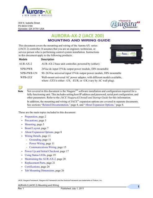
This document covers the mounting <strong>and</strong> wiring of the Aurora-AX series<br />
(<strong>JACE</strong> 2) controller. It assumes that you are an engineer, technician, or<br />
service person who is performing control system installation. Instructions<br />
in this document apply to the following products:<br />
Models Description<br />
AUR-AX-2 AUR-AX-2 base unit controller, powered by (either):<br />
NPB-PWR 24Vac/dc input/15Vdc output power module, DIN mountable<br />
NPB-PWR-UN 90–263Vac universal input/15Vdc output power module, DIN mountable<br />
WPB-XXX Wall-mount universal AC power adapter, with different models available,<br />
where -XXX is either: -US, -EUR, or -UK (vary by AC wall plug).<br />
Note Not covered in this document is the Niagara AX software installation <strong>and</strong> configuration required for a<br />
fully functioning unit. This includes setting host IP address <strong>and</strong> password, serial port configuration, <strong>and</strong><br />
other parameters. Refer to the <strong>JACE</strong> NiagaraAX Install <strong>and</strong> Startup <strong>Guide</strong> for this information.<br />
In addition, the mounting <strong>and</strong> wiring of <strong>JACE</strong> ® expansion options are covered in separate documents.<br />
See sections ―Related Documentation,‖ page 4, <strong>and</strong> ―About Expansion Options,‖ page 8.<br />
These are the main topics included in this document:<br />
• Preparation, page 2<br />
• Precautions, page 3<br />
• <strong>Mounting</strong>, page 5<br />
• Board Layout, page 7<br />
• About Expansion Options, page 8<br />
• <strong>Wiring</strong> Details, page 11<br />
– Grounding, page 11<br />
– Power <strong>Wiring</strong>, page 11<br />
– Communications <strong>Wiring</strong>, page 15<br />
• Power Up <strong>and</strong> Initial Checkout, page 17<br />
• Using Status LEDs, page 19<br />
• Maintaining the AUR-AX-2, page 20<br />
• Replacement Parts, page 21<br />
• Certifications, page 24<br />
• Tab <strong>Mounting</strong> Dimensions, page 26<br />
AURORA-AX-2 (<strong>JACE</strong> <strong>200</strong>)<br />
<strong>JACE</strong>, Niagara Niagara AX <strong>and</strong> the Sedona are of Inc.<br />
AUR-AX-2 (<strong>JACE</strong> 2) <strong>Mounting</strong> <strong>and</strong> <strong>Wiring</strong><br />
Rev <strong>Guide</strong> 1 Published: July 1, 2011<br />
1
Included in this Package<br />
Preparation<br />
2<br />
Published: July 1, 2011<br />
Preparation<br />
Unpack the AUR-AX-2 <strong>and</strong> power module (NPB-PWR, NPB-PWR-UN, or WPM-XXX) <strong>and</strong> inspect the<br />
package contents for damaged or missing components. If damaged, notify the appropriate carrier at once <strong>and</strong><br />
return any damaged components for immediate repair or replacement. See ―Returning a Defective Unit‖ on<br />
page 23.<br />
• Included in this Package<br />
• Material <strong>and</strong> Tools Required<br />
Included in this Package<br />
Included in this package you should find the following items:<br />
• a AUR-AX-2 or AUR-AX-2-USA base controller.<br />
• This AUR-AX-2 (<strong>JACE</strong> 2) <strong>Mounting</strong> <strong>and</strong> <strong>Wiring</strong> <strong>Guide</strong>, Rev 1<br />
• a hardware bag containing the following items:<br />
– A grounding wire, with quick-disconnect 0.187‖ female connector.<br />
• a power module (if ordered), which is required for operation.<br />
The power module can be one of the following:<br />
– NPB-PWR: 24Vac in-line, DIN-mount capable, with grounding wire, or<br />
– NPB-PWR-UN: 90-263 Vac in-line, DIN-mount capable, with grounding wire, or<br />
– WPM-XXX: External wall-mount power adapter (input: 90–254Vac, 50–60 Hz, output: 15Vdc, 1A)<br />
where XXX varies by the AC wall plug (for installation locale), such as:<br />
WPM-US (U.S. or Japan installations), WPM-EUR (European installations, type ―C‖ plug)<br />
WPM-UK (United Kingdom installations, type ―B‖ plug)<br />
Material <strong>and</strong> Tools Required<br />
The following supplies <strong>and</strong> tools may be required for installation:<br />
• DIN rail, type NS35/7.5 (35mm x 7.5mm) <strong>and</strong> DIN rail end-clips (stop clips), recommended for any<br />
installation that includes NPB-PWR or NPB-PWR-UN module <strong>and</strong>/or optional I/O modules.<br />
Note Length of DIN rail is determined by the number of optional DIN-mounted options.<br />
See Figure 1 on page 6 for more details.<br />
• If using a NPB-PWR power module, either one of the following:<br />
– UL listed, Class 2, 24Vac transformer, rated at minimum of 8.5VA to 20VA (approximate range of<br />
<strong>JACE</strong>-2 alone, to fully-exp<strong>and</strong>ed unit with four additional AUR-IO-16 modules <strong>and</strong> other option<br />
boards). Note that a dedicated transformer is required (cannot also power additional equipment).<br />
– 24Vdc power supply, capable of supplying at least 1A (24W).<br />
• Suitable screws <strong>and</strong> screwdriver for mounting DIN rail, or if DIN rail not used, for mounting bases of<br />
AUR-AX-2 controller, NPB-PWR or NPB-PWR-UN module (if used), <strong>and</strong> any I/O modules (if used).<br />
• #2 phillips screwdriver: used to install <strong>and</strong> remove optional communications modules.<br />
• Small flat-blade screwdriver: used for mounting or removing the AUR-AX-2 from DIN rail, also for<br />
making wiring connections to RS-485 connector, <strong>and</strong> optionally LON <strong>and</strong> I/O connectors.<br />
AUR-AX-2 (<strong>JACE</strong> 2) <strong>Mounting</strong> <strong>and</strong> <strong>Wiring</strong><br />
<strong>Guide</strong><br />
Part Number 11842 Rev 1
Precautions<br />
Precautions<br />
This document uses the following warning <strong>and</strong> caution conventions:<br />
AUR-AX-2 (<strong>JACE</strong> 2) <strong>Mounting</strong> <strong>and</strong> <strong>Wiring</strong> <strong>Guide</strong><br />
Part Number 11842 Rev 1 Published: July 1, 2011<br />
Safety Precautions<br />
Caution Cautions remind the reader to be careful. They alert readers to situations where there is a chance<br />
that the reader might perform an action that cannot be undone, might receive unexpected results, or<br />
might lose data. Cautions contain an explanation of why the action is potentially problematic.<br />
Warning Warnings alert the reader to proceed with extreme care. They alert readers to situations where there<br />
is a chance that the reader might do something that can result in personal injury or equipment<br />
damage. Warnings contain an explanation of why the action is potentially dangerous.<br />
Safety Precautions<br />
The following items are warnings of a general nature relating to the installation <strong>and</strong> start-up of the AUR-<br />
AX-2 controller. Be sure to heed these warnings to prevent personal injury or equipment damage.<br />
Warning • Depending on power module used, the circuit powering the AUR-AX-2 is 90–263Vac at 50/60<br />
Hz (if using NPB-PWR-UN), 24Vac at 50/60 Hz or 24Vdc (if using NPB-PWR-UN), or from<br />
100–240Vac at 50/60 Hz (if using WPM-XXX). Disconnect power before installation or servicing<br />
to prevent electrical shock or equipment damage.<br />
• Make all connections in accordance with national <strong>and</strong> local electrical codes. Use copper<br />
conductors only.<br />
• To reduce the risk of fire or electrical shock, install in a controlled environment relatively free<br />
of contaminants.<br />
• This device is only intended for use as a monitoring <strong>and</strong> control device. To prevent data loss or<br />
equipment damage, do not use it for any other purpose.<br />
Static Discharge Precautions<br />
Static charges produce voltages high enough to damage electronic components. The microprocessors <strong>and</strong><br />
associated circuitry within a AUR-AX-2 controller are sensitive to static discharge. Follow these precautions<br />
when installing, servicing, or operating the system:<br />
Caution • Work in a static-free area.<br />
• Discharge any static electricity you may have accumulated. Discharge static electricity by<br />
touching a known, securely grounded object.<br />
• Do not h<strong>and</strong>le the printed circuit board (PCB) without proper protection against static discharge.<br />
Use a wrist strap when h<strong>and</strong>ling PCBs. The wrist strap clamp must be secured to earth ground.<br />
3
Battery Precautions<br />
Battery Precautions<br />
4<br />
Published: July 1, 2011<br />
Related Documentation<br />
Caution • The NiMH battery used in this device may present a risk of fire or chemical burn if mistreated.<br />
Do not disassemble, heat above 122ºF (50ºC), or incinerate. Replace battery pack with type<br />
NPB-BATT only. Use of another battery may present a risk of fire or explosion.<br />
• Dispose of used battery promptly. Keep away from children. Do not disassemble <strong>and</strong> do not<br />
dispose of in fire.<br />
WEEE (Waste of Electrical <strong>and</strong> Electronic Equipment)<br />
Recycling of Electronic Products: (International Installations)<br />
In <strong>200</strong>6 the European Union adopted regulations (WEEE) for the collection <strong>and</strong> recycling of all waste electrical<br />
<strong>and</strong> electronic equipment. It is no longer allowable to simply throw away such equipment. Instead, these products<br />
must enter the recycling process. To properly dispose of this product, please take it to a local recycling center.<br />
If a local recycling center cannot be found, please return it to one of these offices:<br />
Tridium Europe Ltd<br />
1, The Grainstore Brooks<br />
Green Road Coolham, West<br />
Sussex RH138GR United<br />
Kingdom<br />
Tridium Asia Pacific Pte Ltd<br />
17 Changi Business Park Central 1<br />
Honeywell Building<br />
Singapore 486073<br />
Related Documentation<br />
Tridium Inc.<br />
2256 Dabney Road, Suite C<br />
Richmond, VA 23230<br />
For more details on configuring <strong>and</strong> using the AUR-AX-2 (<strong>JACE</strong> 2) controller, consult the following<br />
documents:<br />
• <strong>JACE</strong> NiagaraAX Install <strong>and</strong> Startup <strong>Guide</strong><br />
• AUR-IO-16 Installation <strong>and</strong> Configuration <strong>Guide</strong><br />
• AUR-IO-34 Installation <strong>and</strong> Configuration <strong>Guide</strong><br />
• Various option card installation documents, such as:<br />
– NPB-LON Option Install Sheet<br />
– NPB-2X-485 Option Install Sheet<br />
– NPB-232 Option Install Sheet<br />
See the ―About Option Cards‖ section on page 8 for a listing of option card types.<br />
• NiagaraAX Ndio <strong>Guide</strong><br />
• NiagaraAX User <strong>Guide</strong><br />
AUR-AX-2 (<strong>JACE</strong> 2) <strong>Mounting</strong> <strong>and</strong> <strong>Wiring</strong> <strong>Guide</strong><br />
Rev 1
<strong>Mounting</strong><br />
<strong>Mounting</strong><br />
AUR-AX-2 (<strong>JACE</strong> 2) <strong>Mounting</strong> <strong>and</strong> <strong>Wiring</strong> <strong>Guide</strong><br />
Part Number 11842 Rev 1 Published: July 1, 2011<br />
Environmental Requirements<br />
Mount the AUR-AX-2 controller in a location that allows clearance for wiring, servicing, <strong>and</strong> module removal.<br />
Environmental Requirements<br />
Note the following requirements for the controller’s mounting location:<br />
• This product is intended for indoor use only. Do not expose the unit to ambient conditions outside of the<br />
range of 0ºC (32º F) to 50ºC (122º F) <strong>and</strong> relative humidity outside the range 5% to 95% non-condensing<br />
(pollution degree 1).<br />
• If mounting inside an enclosure, that enclosure should be designed to keep the unit within its required<br />
operating range considering a 20-watt dissipation by the controller, plus dissipation from any other<br />
devices installed in the same enclosure. This is especially important if the controller is mounted inside an<br />
enclosure with other heat producing equipment.<br />
• Do not mount the unit:<br />
– in an area where excessive moisture, corrosive fumes, or explosive vapors are present.<br />
– where vibration or shock is likely to occur.<br />
– in a location subject to electrical noise. This includes the proximity of large electrical contractors,<br />
electrical machinery, welding equipment, <strong>and</strong> spark igniters, <strong>and</strong> variable frequency drives.<br />
Physical <strong>Mounting</strong><br />
The following information applies about physically mounting the unit.<br />
• You can mount the AUR-AX-2 in any orientation. It it not necessary to remove the cover before mounting.<br />
• <strong>Mounting</strong> on a 35mm wide DIN rail is recommended. The controller’s base has a molded DIN rail slot<br />
<strong>and</strong> locking clip, as do power modules (NPB-PWR, NPB-PWR-UN) <strong>and</strong> both types of I/O expansion<br />
modules. <strong>Mounting</strong> on a DIN rail ensures accurate alignment of connectors between all modules.<br />
• If DIN rail mounting is impractical, you can use screws in mounting tabs on the AUR-AX-2, then<br />
in any end-connected accessory (NPB-PWR, etc.). Tab dimensions are on the last page of this<br />
document.<br />
The following procedure provides step-by-step DIN rail mounting instructions for the controller.<br />
Note Mount the controller prior to mounting any accessory module (power module, I/O modules).<br />
Procedure 1 To mount on DIN rail<br />
Step 1 Securely install the DIN rail using at least two screws, near both ends of the rail.<br />
Step 2 Position the AUR-AX-2 on the rail, tilting to hook DIN rail tabs over one edge of the DIN rail (Figure<br />
1).<br />
Step 3 Use a screwdriver to pry down the plastic locking clip, <strong>and</strong> push down <strong>and</strong> in on the controller, to force<br />
the locking clip to snap over the other edge of the DIN rail.<br />
Step 4 Mount any accessory item (NPB-PWR, I/O module) onto the DIN rail in the same manner.<br />
Step 5 Slide the accessory along the DIN rail to connect its 20-position plug into the controller.<br />
Step 6 Repeat this for all accessories, until all are mounted on the DIN rail <strong>and</strong> firmly connected to each other.<br />
Step 7 To keep the final assembly together, secure at both ends with DIN rail end-clips provided by the DIN<br />
rail vendor. This also prevents the assembly from sliding on the DIN rail. See Figure 1.<br />
5
Removing <strong>and</strong> Replacing the Cover<br />
Figure 1 AUR-AX-2 controller <strong>and</strong> accessory mounting details.<br />
6<br />
<strong>Mounting</strong> on DIN Rail<br />
DIN rail<br />
End Clip<br />
4.1‖<br />
(104 mm)<br />
AUR-<br />
AX-2<br />
AUR-<br />
AX-2<br />
Published: July 1, 2011<br />
Removing from DIN Rail<br />
NPB-PWR or<br />
NPB-PWR-UN<br />
Up to four (4)<br />
AUR-IO-16<br />
modules<br />
7.13‖ (181 mm) are supported.<br />
6.38‖ (162 mm)<br />
Install DIN rail End Clip<br />
DIN Rail (Stop Clip) at both ends of<br />
End Clip final assembly.<br />
AUR-IO-16<br />
NPB-PWR or<br />
2.05‖ (52 mm) AUR-IO-16 AUR-IO-16 AUR-IO-16 AUR-IO-16 NPB-PWR-UN<br />
AUR-<br />
AX-2<br />
<strong>Mounting</strong><br />
10.35‖ (263 mm)<br />
NOTE: If installing<br />
AUR-IO-16 modules <strong>and</strong><br />
13.58‖ (345 mm)<br />
using the NPB-PWR or<br />
NPB-PWR-UN power<br />
16.81‖ (427 mm) supply module, the power<br />
supply module installs at<br />
20.04‖ (509 mm) the end of the chain.<br />
Removing <strong>and</strong> Replacing the Cover<br />
23.27‖ (591 mm)<br />
You must remove the AUR-AX-2 cover to connect the battery (new unit) or to replace the battery, <strong>and</strong> to<br />
install any option boards. The cover snaps onto the base with four plastic tabs (two on each end).<br />
To remove the cover, press in the four tabs on both ends of the unit, <strong>and</strong> lift the cover off. See Figure 2.<br />
AUR-AX-2 (<strong>JACE</strong> 2) <strong>Mounting</strong> <strong>and</strong> <strong>Wiring</strong> <strong>Guide</strong><br />
Rev 1
Board Layout<br />
Figure 2 Press in four tabs on ends of cover to remove cover.<br />
Cover Tabs<br />
(2 each end)<br />
Press<br />
Tabs In<br />
AUR-AX-2 (<strong>JACE</strong> 2) <strong>Mounting</strong> <strong>and</strong> <strong>Wiring</strong> <strong>Guide</strong><br />
Part Number 11842 Rev 1 Published: July 1, 2011<br />
Removing <strong>and</strong> Replacing the Cover<br />
Note If accessory modules are plugged into the controller, you may need to slide them away from the unit to<br />
get to the cover tabs.<br />
To replace the cover, orient it so the cutout area for comm ports is correct, then push inwards to snap in place.<br />
Board Layout<br />
Figure 3 shows the location of LEDs, option slots, <strong>and</strong> other features of the AUR-AX-2 controller with<br />
cover removed. For a side view of communications ports <strong>and</strong> other features, see Figure 6 on page 15.<br />
Figure 3 AUR-AX-2 controller board layout details.<br />
Option Slot 2<br />
Battery Bracket<br />
(on top of option<br />
cards, if any)<br />
NiMH Battery<br />
Connector<br />
(see Figure 7<br />
on page 17)<br />
Option Slot<br />
Connectors<br />
Option Slot 1<br />
Serial port LEDs on bottom<br />
board, remove cover to see:<br />
COM 1 COM 2<br />
Secondary<br />
Ethernet (RJ-45)<br />
LAN2 (top board)<br />
RS-232<br />
(DB-9)<br />
COM1<br />
Primary<br />
Ethernet<br />
(RJ-45)<br />
LAN1<br />
(top<br />
board)<br />
Status LEDs (visible with cover on):<br />
LAN2 LAN1 BEAT STATUS<br />
RS-485<br />
(3-pos.)<br />
COM2<br />
(bottom<br />
board)<br />
Cover<br />
lifted<br />
away<br />
20 Pin<br />
Connector<br />
(I/O <strong>and</strong><br />
Power<br />
Modules)<br />
Mode Jumper<br />
(for serial shell<br />
access)<br />
Earth Ground<br />
Spade Lug<br />
Barrel power<br />
connector for wall<br />
mounted power<br />
module (WPM-XXX).<br />
7
About Option Cards<br />
About Expansion Options<br />
The AUR-AX-2 controller provides for field-installable expansion with two kinds of options:<br />
8<br />
Published: July 1, 2011<br />
About Expansion Options<br />
• Option cards—Install on connectors inside the controller base unit. See ―About Option Cards‖.<br />
• Accessory modules—To ―chain‖ on the AUR-AX-2’s 20-pin end connector. See ―About Accessory<br />
Modules‖.<br />
About Option Cards<br />
The AUR-AX-2 has two (2) option slots for custom option cards designed for use with <strong>JACE</strong> controllers. Each<br />
slot has a 30-pin connector on the controller’s base board. See Figure 3 on page 7.<br />
Warning Power to the controller must be OFF when installing or removing option cards, or damage will occur!<br />
Also, you must be very careful to plug an option card into its connector properly (pins aligned).<br />
Option cards typically provide additional communications features, such as with the following available models<br />
(with others still in development) listed in Table 1.<br />
Table 1 AUR-AX-2 option cards.<br />
Model Description Notes<br />
NPB-LON FTT-10A LON (LonWorks) adapter<br />
with a 2-position removable<br />
screw-terminal connector plug.<br />
NPB-2X-485 Dual, optically-isolated, RS-485<br />
adapter with two 3-position<br />
removable screw-terminal<br />
connector plugs.<br />
NPB-MDM 56Kbps Auto-dial/Auto-answer<br />
Modem with one RJ-11 connector<br />
for phone line.<br />
Note: Not supported if NPB-GPRS<br />
modem option is also installed.<br />
NPB-232 Single port RS-232 adapter, with a<br />
DB-9M connector. Uses its own<br />
on-board UART. Supports baud<br />
rates up to 115<strong>200</strong>.<br />
NPB-GPRS-W<br />
NPB-GPRS<br />
<strong>Wireless</strong> GSM cellular modem<br />
using GPRS (General Packet<br />
Radio Service) data technology,<br />
powered by the controller.<br />
NPB-SED-001 Sedona Framework option card<br />
with Jennic JN5139 microcontroller<br />
<strong>and</strong> Sedona module for 802.15.4<br />
wireless network <strong>and</strong> 6LoWPAN<br />
bridge support. Wired RS-485<br />
MSTP networking also supported.<br />
Up to 2 LON option cards may be installed.<br />
• If one LON option, it operates as LON1, regardless of slot.<br />
• If two LON options, LON1 is Option slot 1, LON2 is Option slot 2.<br />
One or two 485 option cards may be installed.<br />
If installed in Option slot 1, ports are COM3 <strong>and</strong> COM4. If two 485 options<br />
are installed, ports are COM3 <strong>and</strong> COM4 for Option slot 1, <strong>and</strong> COM5 <strong>and</strong><br />
COM6 for Option slot 2.<br />
Maximum of one. Does not have own UART (unlike NPB-2X-485,<br />
NPB-232, etc.). Must be installed in Option slot 1, where it operates as<br />
COM1. This disables the RS-232 base serial port (DB-9 connector) on the<br />
AUR-AX-2 during normal operation.<br />
Note: If a NPB-MDM is installed, <strong>and</strong> the ―mode jumper‖ (see Figure 3) is<br />
put in ―Serial Shell‖ position, the AUR-AX-2 base RS-232 port becomes<br />
active immediately following a reboot. This allows an RS-232 connection<br />
to the ―serial shell‖ for debugging purposes. To re-enable the modem, you<br />
must put the mode jumper back in the ―Normal‖ position, <strong>and</strong> reboot<br />
again.<br />
One or two 232 option cards may be installed.<br />
If installed in Option slot 1, port is COM3. If two 232 options are installed,<br />
ports are COM3 for Option slot 1, <strong>and</strong> COM4 for Option slot 2<br />
Requires AX-3.4 or later. One GPRS option card is supported.<br />
Includes SMA coax stub antenna.<br />
The NPB-GPRS-W model is bundled with a Wyless provisioned SIM card.<br />
The NPB-GPRS model does not include a SIM card.<br />
Requires AX-3.4 or later. One Sedona option card is supported.<br />
Includes RP-SMA coax stub antenna. If installed in Option slot 1, is COM3.<br />
For more details on port assignments <strong>and</strong> other features, refer to specific option card installation documents.<br />
AUR-AX-2 (<strong>JACE</strong> 2) <strong>Mounting</strong> <strong>and</strong> <strong>Wiring</strong> <strong>Guide</strong><br />
Rev 1
About Expansion Options<br />
AUR-AX-2 (<strong>JACE</strong> 2) <strong>Mounting</strong> <strong>and</strong> <strong>Wiring</strong> <strong>Guide</strong><br />
Part Number 11842 Rev 1 Published: July 1, 2011<br />
About Option Cards<br />
<strong>Mounting</strong> Option Cards<br />
Refer to the installation document that accompanies a specific option card for complete details. The following<br />
procedure provides a basic set of steps.<br />
Procedure 2 <strong>Mounting</strong> option cards on a AUR-AX-2 controller.<br />
Step 1 Remove power from the controller—see the previous Warning.<br />
Step 2 Remove the cover. See ―Removing <strong>and</strong> Replacing the Cover,‖ page 6.<br />
Step 3 Remove the battery <strong>and</strong> bracket assembly by taking out the four screws holding it in place, setting the<br />
screws aside for later. Unplug the battery from the connector on the controller’s base board.<br />
Step 4 Remove the blanking end plate for the slot you are installing the option card into.<br />
(Retain the blanking plate in case the option card must be removed at a later date.)<br />
Step 5 Carefully insert the pins of the option card into the socket of the appropriate option card slot.<br />
The mounting holes on the option board should line up with the st<strong>and</strong>offs on the base board. If they<br />
do not, the connector is not properly aligned. Press until the option card is completely seated.<br />
Step 6 Place the custom end plate that came with the option card over the connector(s) of the option card.<br />
Step 7 Plug the battery connector plug into the battery connector on the controller’s base board.<br />
Step 8 Set the battery <strong>and</strong> bracket assembly back over the option card slots, with the mounting holes aligned<br />
with the st<strong>and</strong>offs.<br />
Step 9 Place the four screws through the battery bracket, end plates, <strong>and</strong> into the st<strong>and</strong>offs on the controller’s<br />
base board. Using a screwdriver, h<strong>and</strong> tighten these screws.<br />
Step 10 Replace the cover.<br />
9
About Accessory Modules<br />
About Accessory Modules<br />
1<br />
0<br />
Published: July 1, 2011<br />
About Expansion Options<br />
The AUR-AX-2 controller has a 20-pin, right-angle, Euro-DIN connector that accepts custom-built accessory<br />
modules. The connector provides power <strong>and</strong> signal lines to any connected modules, <strong>and</strong> is located on the end of<br />
the AUR-AX-2 opposite to the option cards.<br />
Warning • Power to the controller must be OFF when inserting or unplugging accessory modules.<br />
Wait for all LED activity to stop (all LEDs to be off).<br />
• Also, do not connect live voltages to the inputs or outputs of an I/O module (AUR-IO-16 or AUR-<br />
IO-34)<br />
while it is in an “un-powered state” before plugging the module into a AUR-AX-2.<br />
Otherwise, damage to the I/O module <strong>and</strong>/or the controller may result!<br />
Each accessory module has a DIN-mount base, <strong>and</strong> typically provides two (2) 20-pin connectors that allow you<br />
to ―chain‖ multiple accessories (see Procedure 1 on page 5). Table 2 lists currently available accessory modules.<br />
Table 2 AUR-AX-2 accessory modules.<br />
Model Description Notes<br />
NPB-PWR DIN-mountable, 24V isolated power<br />
module, used to power AUR-AX-2<br />
from a dedicated, external, Class-2,<br />
24Vac transformer or a 24Vdc power<br />
NPB-PWR-UN<br />
supply.<br />
DIN-mountable, Universal 90–263<br />
Vac input, 15Vdc output, 30W power<br />
supply to power AUR-AX-2.<br />
AUR-IO-16 DIN-mountable, 16 points I/O module,<br />
used to provide I/O points as noted.<br />
AUR-IO-34 DIN-mountable, combined 34 points<br />
I/O with 24V isolated power module,<br />
used to provide I/O points as well as<br />
power AUR-AX-2 from a dedicated,<br />
external, Class-2, 24Vac transformer<br />
or a 24Vdc power supply.<br />
• Only one NPB-PWR per AUR-AX-2 controller.<br />
• Do not install if using WPM-XXX or NPB-PWR-UN.<br />
• <strong>Wiring</strong> is covered in this document, see ―NPB-PWR,‖ page 12.<br />
• Only one NPB-PWR-UN per AUR-AX-2 controller.<br />
• Do not install if using WPM-XXX or NPB-PWR.<br />
• <strong>Wiring</strong> is covered in this document, see ―NPB-PWR-UN,‖ page 13.<br />
Provides the following I/O points:<br />
• 8 - Universal Inputs (UIs).<br />
• 4 - Digital Outputs (DOs), SPST-relay type.<br />
• 4 - Analog Outputs, 0–10Vdc type.<br />
Up to four (maximum) AUR-IO-16 accessory modules are<br />
supported. <strong>Wiring</strong> is covered in a separate document, see the<br />
AUR-IO-16 Installation <strong>and</strong> Configuration <strong>Guide</strong>.<br />
Only one AUR-IO-34 per AUR-AX-2. Provides the following I/O points:<br />
• 16 - Universal Inputs (UIs).<br />
• 10 - Digital Outputs (DOs), SPST-relay type.<br />
• 8 - Analog Outputs, 0–10Vdc type.<br />
Up to 2 additional AUR-IO-16 modules can be used. Do not power the<br />
AUR-IO-34 if using WPM-XXX.<br />
<strong>Wiring</strong> is covered in a separate document, see the<br />
AUR-IO-34 Installation <strong>and</strong> Configuration <strong>Guide</strong>.<br />
AUR-AX-2 (<strong>JACE</strong> 2) <strong>Mounting</strong> <strong>and</strong> <strong>Wiring</strong> <strong>Guide</strong><br />
Rev 1
<strong>Wiring</strong> Details<br />
<strong>Wiring</strong> Details<br />
See Figure 3 on page 7 to locate connectors <strong>and</strong> other components on the AUR-AX-2<br />
controller. Make connections to the controller in the following order.<br />
Grounding<br />
1. Install any option cards (LON, RS-485, RS-232, etc.) in option slots 1 <strong>and</strong> 2. See ―<strong>Mounting</strong> Option<br />
Cards,‖ page 9 for a general procedure. For complete details, refer to the specific installation document<br />
that shipped with the option card.<br />
2. Connect supplied earth grounding wires (with spade connector) from the earth ground lug on the AUR-<br />
AX-2 <strong>and</strong> any accessory modules (if used) to a nearby earth grounding point. See ―Grounding‖ for<br />
details.<br />
3. Prepare power wiring (leave the unit powered off). See ―Power <strong>Wiring</strong>‖ for details.<br />
4. Connect communications cables. See ―Communications <strong>Wiring</strong>,‖ page 15 for ports available on the AUR-<br />
AX-2 base unit. For ports on any installed option board (LON, RS-485, modem) see the specific<br />
mounting <strong>and</strong> wiring guide for any additional details.<br />
5. If IO accessory modules are installed, connect the I/O wiring. Refer to the appropriate mounting <strong>and</strong><br />
wiring guide for complete details.<br />
6. Connect the backup battery to the AUR-AX-2 battery connector, <strong>and</strong> apply power to the unit. See<br />
―Power Up <strong>and</strong> Initial Checkout,‖ page 17.<br />
Grounding<br />
An earth ground spade lug (0.187") is provided on the base of the AUR-AX-2 for connection to earth ground.<br />
For maximum protection from electrostatic discharge or other forms of EMI, connect the supplied earth<br />
grounding wire to this lug <strong>and</strong> a nearby earth ground (see Figure 4 on page 12). Keep this wire as short as<br />
possible.<br />
Power is provided for plug-in accessory modules through the 20-pin accessory connectors. However, you should<br />
also connect the earth ground spade lug of each accessory module to ground in the same manner.<br />
Power <strong>Wiring</strong><br />
The AUR-AX-2 controller must be powered by an approved 15 Vdc power source. This can be either 1 a DINmount<br />
24Vac/dc-powered module (NPB-PWR), a DIN-mount line-powered (90–263 Vac) module (NPB-PWR-UN),<br />
or an external wall mount AC adapter (WPM-XXX).<br />
The AUR-AX-2 controller does not include an on/off switch. To apply power, you either:<br />
• if NPB-PWR, plug in its 2-position power connector.<br />
• if NPB-PWR-UN, energize the AC circuit (90–263 Vac) wired to that module.<br />
• if WPM-XXX, plug in the power connector to the AUR-AX-2.<br />
Caution Do not connect both the WPM-XXX <strong>and</strong> NPB-PWR / NPB-PWR-UN supplies at the same time, or<br />
equipment damage may result.<br />
1. A fourth power option is available: a AUR-IO-34 accessory module, which is a combination of the NPB-PWR module <strong>and</strong><br />
AUR-AX-2 (<strong>JACE</strong> 2) <strong>Mounting</strong> <strong>and</strong> <strong>Wiring</strong> <strong>Guide</strong><br />
Part Number 11842 Rev 1 Published: July 1, 2011<br />
11
1<br />
2<br />
two AUR-IO-16 modules (plus two extra relays). Please refer to its mounting <strong>and</strong> wiring instructions document for more<br />
details. For general information on accessory modules, see ―About Accessory Modules,‖ page 10.<br />
Published: July 1, 2011<br />
AUR-AX-2 (<strong>JACE</strong> 2) <strong>Mounting</strong> <strong>and</strong> <strong>Wiring</strong> <strong>Guide</strong><br />
Rev 1
Power <strong>Wiring</strong><br />
AUR-AX-2 (<strong>JACE</strong> 2) <strong>Mounting</strong> <strong>and</strong> <strong>Wiring</strong> <strong>Guide</strong><br />
Part Number 11842 Rev 1 Published: July 1, 2011<br />
<strong>Wiring</strong> Details<br />
If desired, you can use the wall mount WPM-XXX in your office (to initially commission the AUR-AX-2), <strong>and</strong><br />
then install the AUR-AX-2 at the job using either a NPB-PWR or NPB-PWR-UN module. The following<br />
sections provide more details:<br />
• NPB-PWR (24Vac/dc-powered in-line module)<br />
• NPB-PWR-UN (Universal 90V–263Vac-powered in-line module)<br />
• WPM-XXX (Wall Power Modules)<br />
NPB-PWR<br />
Using the NPB-PWR module lets you power the AUR-AX-2 (<strong>and</strong> if installed, AUR-IO-16 modules) from a<br />
dedicated Class 2, 24Vac transformer, or from a 24Vdc power supply. If installing AUR-IO-16 modules, the<br />
NPB-PWR installs as the last (end) module in the chain. See Figure 1 on page 6.<br />
Note If powering from a 24V transformer, do not power any other equipment with it. Otherwise, conducted<br />
noise problems may result. Also, do not ground either side of the transformer’s 24V secondary.<br />
Figure 4 NPB-PWR module wiring connections.<br />
AUR-AX-2<br />
Dedicated 24Vac Transformer<br />
neither side of secondary tied<br />
to earth ground<br />
Line Voltage<br />
(Mains)<br />
NPB-PWR (cover removed)<br />
24Vac<br />
or<br />
Earth Ground<br />
+ 24Vdc<br />
–<br />
24Vdc Power Supply<br />
(Polarity Not Critical)<br />
neither side tied to earth<br />
Located at the bottom of the NPB-PWR module is a 2-position power connector, <strong>and</strong> an earth ground spade lug,<br />
as shown in Figure 4.<br />
Connect the supplied earth ground wire to a nearby earth ground point. Unplug the power connector plug from<br />
the module <strong>and</strong> make connections to it as shown in Figure 4.<br />
Caution Do not plug 24V power into the NPB-PWR (reinsert connector plug) until all other mounting <strong>and</strong><br />
wiring is completed. See ―Power Up <strong>and</strong> Initial Checkout,‖ page 17.<br />
Power consumption depends on installed accessories <strong>and</strong> option boards, <strong>and</strong> may vary from:<br />
• AUR-AX-2 with NPB-PWR module alone: approximately 8.5 VA (AC) or 8.5 W (DC)<br />
• AUR-AX-2 with NPB-PWR <strong>and</strong> four (4) AUR-IO-16 modules, <strong>and</strong> option cards: up to 20 VA (AC) or 20 W<br />
(DC)<br />
13
1<br />
4<br />
<strong>Wiring</strong> Details<br />
Published: July 1, 2011<br />
AUR-AX-2 (<strong>JACE</strong> 2) <strong>Mounting</strong> <strong>and</strong> <strong>Wiring</strong> <strong>Guide</strong><br />
Power <strong>Wiring</strong><br />
NPB-PWR-UN<br />
The NPB-PWR-UN module lets you power the AUR-AX-2 (<strong>and</strong> if installed, AUR-IO-16 modules) from AC<br />
line power, with a universal input range from 90–263Vac. If installing AUR-IO-16 modules, the NPB-PWR-<br />
UN installs as the last (end) module in the chain. See Figure 1 on page 6.<br />
Warning • A 120Vac or 240Vac circuit powers the NPB-PWR-UN. Disconnect power to this circuit<br />
before installation to prevent electrical shock of equipment damage.<br />
• Make all connections in accordance with national <strong>and</strong> local electrical codes. Use copper<br />
conductors only.<br />
• Do not exceed the 30W capacity of the NPB-PWR-UN by the powered devices.<br />
Power input connections are made to the terminals on the circuit board (cover removal is required). An earth<br />
ground connection must be made to the grounding lug using the supplied earth wire. See Figure 5.<br />
Figure 5 NPB-PWR-UN module wiring connections.<br />
Remove cover<br />
<strong>JACE</strong> or<br />
last<br />
AUR-IO-<br />
16<br />
120 or 240Vac<br />
50–60 Hz<br />
Single Phase<br />
Line<br />
Neutral<br />
L N<br />
AC Input<br />
Earth Ground<br />
6-pin<br />
connector<br />
not used<br />
Procedure 3 <strong>Wiring</strong> NPB-PWR-UN input power <strong>and</strong> earth ground.<br />
NOTE: The 6-pin connector of the NPB-PWR-UN is<br />
not used with a AUR-AX-2 series controller.<br />
The 6-pin connector is designed for use with other<br />
controllers or modules, <strong>and</strong> must be left unused.<br />
Step 1 Remove power from the AC circuit being wired to the NPB-PWR-UN—see previous Warning •.<br />
Step 2 Remove the NPB-PWR-UN cover.<br />
To do this, press in the four tabs on both ends of the unit, <strong>and</strong> lift the cover off.<br />
Step 3 If the controller or a AUR-IO-16 accessory module is plugged into the unit, you may need to slide it<br />
away to get to the cover tabs.<br />
Step 4 Connect the supplied earth grounding wire to a nearby grounding point. See Figure 5.<br />
Step 5 Make AC circuit connections line (mains) <strong>and</strong> neutral to the terminals labeled ―INPUT PWR.‖<br />
Step 6 Replace the cover on the NPB-PWR-UN.<br />
Make sure all modules in the mounted assembly are firmly connected together <strong>and</strong> secured.<br />
Caution Do not energize the AC circuit wired to the NPB-PWR-UN until all other <strong>JACE</strong> mounting <strong>and</strong><br />
wiring is completed. See ―Power Up <strong>and</strong> Initial Checkout,‖ page 17.<br />
Rev 1
Power <strong>Wiring</strong><br />
AUR-AX-2 (<strong>JACE</strong> 2) <strong>Mounting</strong> <strong>and</strong> <strong>Wiring</strong> <strong>Guide</strong><br />
Part Number 11842 Rev 1 Published: July 1, 2011<br />
<strong>Wiring</strong> Details<br />
WPM-XXX<br />
All models of wall power modules (US, EUR, UK, JA) are self-contained, isolated, switching power supplies<br />
designed to plug into a st<strong>and</strong>ard building power receptacle of appropriate voltage. To supply power to the AUR-<br />
AX-2, you then simply plug the barrel connector plug from the WPM-XXX into the barrel power connector on<br />
the<br />
AUR-AX-2 base board (see Figure 6 on<br />
page 15).<br />
Caution Do not plug the barrel connector plug from the WPM-XXX into the AUR-AX-2 until all other<br />
mounting <strong>and</strong> wiring is completed. See ―Power Up <strong>and</strong> Initial Checkout,‖ page 17.<br />
15
1<br />
6<br />
<strong>Wiring</strong> Details<br />
Communications <strong>Wiring</strong><br />
Published: July 1, 2011<br />
Communications <strong>Wiring</strong><br />
Connect communications wiring to the AUR-AX-2 using ports on the bottom of the unit (Figure 6), which<br />
include:<br />
• Ethernet<br />
• Serial<br />
Note Prior to connecting cables, provide strain relief for them to prevent damage to the controller.<br />
Figure 6 AUR-AX-2 controller bottom side (cover removed).<br />
Battery in bracket<br />
(on top of option<br />
cards, if any)<br />
NiMH<br />
Battery<br />
Connector<br />
Option Slot area<br />
(Slot #1 this side)<br />
Ethernet (RJ-45)<br />
LAN 2<br />
RS-232<br />
(DB-9)<br />
COM1<br />
Primary Ethernet (RJ-45)<br />
LAN 1<br />
s + –<br />
RS-485<br />
(3-pos.)<br />
COM2<br />
Barrel power<br />
connector for<br />
WPM-XXX<br />
20 Pin<br />
Connector<br />
(I/O <strong>and</strong> Power<br />
Modules)<br />
Earth Ground<br />
Spade Lug<br />
Ethernet<br />
Two, female 10/100-Mbit Ethernet connections are provided on the AUR-AX-2. These are RJ-45 connectors<br />
labeled LAN2 <strong>and</strong> LAN1. Use a st<strong>and</strong>ard Ethernet patch cable for connecting to a hub or Ethernet switch. An<br />
activity LED for each Ethernet port is visible, <strong>and</strong> are labeled ―LAN2‖ <strong>and</strong> ―LAN1‖ on the cover.<br />
The factory-default IP address for LAN1 on a AUR-AX-2 is 192.168.1.12n, where the last numeral n in the<br />
address matches the AUR-AX-2’s serial number, <strong>and</strong> subnet mask is 255.255.255.0. By default, LAN2 on a<br />
AUR-AX-2 is disabled. Refer to the <strong>JACE</strong> NiagaraAX Install <strong>and</strong> Startup <strong>Guide</strong> for details on changing IP<br />
address.<br />
Note Typically, you only use LAN1 (primary port), unless you have a specific application for isolating a<br />
driver’s network traffic to a separate LAN, using LAN2. Do not use LAN2 as the primary port.<br />
Serial<br />
There are two serial ports on the AUR-AX-2 base unit. Each has a UART capable of operation up to 115,<strong>200</strong><br />
baud. At the bottom of the board (see Figure 6), the left port is an RS-232 port using a DB-9 plug (male)<br />
connector. To the right of this is a two-wire with shield RS-485 port, using a screw-terminal connector plug.<br />
Note A green ―receive‖ LED <strong>and</strong> yellow ―transmit‖ LED are provided for each serial port. These LEDs are<br />
located on the bottom board, on the opposite side of the serial connectors (see Figure 3 on page 7).<br />
These LEDs are labeled on the board (COM1, COM2) <strong>and</strong> are not visible with the cover on.<br />
AUR-AX-2 (<strong>JACE</strong> 2) <strong>Mounting</strong> <strong>and</strong> <strong>Wiring</strong> <strong>Guide</strong><br />
Rev 1
Communications <strong>Wiring</strong><br />
AUR-AX-2 (<strong>JACE</strong> 2) <strong>Mounting</strong> <strong>and</strong> <strong>Wiring</strong> <strong>Guide</strong><br />
Part Number 11842 Rev 1 Published: July 1, 2011<br />
<strong>Wiring</strong> Details<br />
RS-232—An RS-232 serial port using a male DB-9 connector always operates as COM1. You can use st<strong>and</strong>ard<br />
DB-9 serial cables with this port. The AUR-AX-2 is a serial DTE device, such another DTE device (PC, for<br />
example) requires a ―null modem‖ cable. If connecting the AUR-AX-2 to a DCE device (modem, for<br />
example), a<br />
straight-through cable is used. Table 3 provides st<strong>and</strong>ard serial DB-9 pinouts.<br />
Note If a modem option card (NPB-MDM) is installed, this port becomes disabled—except if rebooted with<br />
the mode jumper (see Figure 3 on page 7) in the ―Serial Shell‖ position.<br />
Table 3 Serial port (RS-232 <strong>and</strong> RS-485) pinouts.<br />
Base RS-232 DB-9 Port (COM1) Base RS-485 Port (COM2)<br />
Pinout References Signal DB-9 Plug Pin Pinouts<br />
DB-9 Plug (male)<br />
1 5<br />
6 9<br />
DCD Data carrier detect 1<br />
RXD Receive data 2<br />
TXD Transmit data 3<br />
DTR Data terminal ready 4<br />
GND Ground 5<br />
DSR Data set ready 6<br />
RTS Request to send 7<br />
CTS Clear to send 8<br />
not used on the AUR-AX-2 9<br />
3-position connector (male)<br />
S + –<br />
RS-485—An RS-485 port uses a 3-position, screw terminal connector <strong>and</strong> always operates as COM2. Wire to<br />
this connector with shielded 18-22AWG wiring (refer to the TIA/EIA-485 st<strong>and</strong>ard). As shown in Table 3, the<br />
screw terminals (from left-to-right) are shield, plus (+), <strong>and</strong> minus (–).<br />
17
1<br />
8<br />
Power Up <strong>and</strong> Initial Checkout<br />
Power Up <strong>and</strong> Initial Checkout<br />
Published: July 1, 2011<br />
Connect the Backup Battery<br />
Ensure power wiring to the AUR-AX-2 controller is ready—see the ―Power <strong>Wiring</strong>‖ section on page 11. Refer<br />
to Figure 3 on page 7 for the locations of the AUR-AX-2 battery connector, status LEDs <strong>and</strong> barrel power<br />
connector (for WPM-XXX only). Refer to Figure 4 on page 12 for location of the power connector on the NPB-<br />
PWR module.<br />
Following all mounting <strong>and</strong> wiring, perform the following:<br />
Procedure 4 Initial power up <strong>and</strong> checkout<br />
Step 1 Connect the Backup Battery.<br />
Step 2 Apply Power.<br />
Step 3 Check the Status LEDs.<br />
Connect the Backup Battery<br />
With the cover removed from the AUR-AX-2 (see ―Removing <strong>and</strong> Replacing the Cover,‖ page 6), locate the red<br />
<strong>and</strong> black wires coming from the NiMH backup battery, with 2-position connector plug. Insert the plug into the<br />
battery connector on the base board (below option slot 2 area), as shown in Figure 7.<br />
Figure 7 NiMH backup battery connector on AUR-AX-2 controller base board.<br />
Battery<br />
Connector<br />
Battery<br />
Assembly<br />
The connector is keyed—you cannot insert it incorrectly. The red (positive) connection should be the furthest<br />
from the two 30-pin option board connectors. For more battery details, see ―About the Battery,‖ page 18.<br />
Apply Power<br />
Apply power to the AUR-AX-2 by plugging in the power plug into either the AUR-AX-2 (if wall mount AC<br />
adapter WPM-XXX) or the 24V-powered NPB-PWR module. If powering using the line-voltage input NPB-<br />
PWR-UN power supply module, energize the 90–263 Vac circuit wired to the module.<br />
Caution Do not connect both the WPM-XXX <strong>and</strong> NPB-PWR / NPB-PWR-UN supplies at the same time, or<br />
equipment damage may result, or a power outage may go unrecognized.<br />
AUR-AX-2 (<strong>JACE</strong> 2) <strong>Mounting</strong> <strong>and</strong> <strong>Wiring</strong> <strong>Guide</strong><br />
Rev 1
Check the Status LEDs<br />
Check the Status LEDs<br />
AUR-AX-2 (<strong>JACE</strong> 2) <strong>Mounting</strong> <strong>and</strong> <strong>Wiring</strong> <strong>Guide</strong><br />
Part Number 11842 Rev 1 Published: July 1, 2011<br />
Power Up <strong>and</strong> Initial Checkout<br />
When power is applied, the green LED labeled ―STATUS‖ will light. This indicates that the system is OK <strong>and</strong><br />
that power is applied. Once the AUR-AX-2 boots, the yellow ―BEAT‖ (heartbeat) LED will begin blinking,<br />
with a typical rate of about 1 Hz. Blinking should begin within 30 seconds after power is applied.<br />
If after applying power, the STATUS LED goes out, or if the BEAT LED comes on (steady) <strong>and</strong> stays lit longer<br />
than two minutes, contact Systems Engineering for technical assistance. See also the ―Using Status LEDs‖<br />
section on page 19.<br />
About the Battery<br />
The AUR-AX-2 is provided with a custom 10-cell NiMH battery pack mounted to the unit (under the cover).<br />
This battery allows the <strong>JACE</strong> to continue operation through very short power bumps (a few seconds in<br />
duration). If a longer power outage occurs, the battery provides enough run time for the AUR-AX-2 to backup<br />
data <strong>and</strong> then shutdown. Typically, this is one minute. Shutdown occurs automatically, after data is backed up<br />
to on-board flash memory.<br />
The AUR-AX-2 charges the battery during normal operation, until fully charged. Typically, the charge<br />
operation completes within 18 hours. Following a power outage, the battery is charged again, as necessary. The<br />
power <strong>and</strong> battery circuitry is monitored by a station running on the <strong>JACE</strong> (via the PowerMonitorService).<br />
Station alarms are generated whenever primary power is lost, or if the battery is uncharged or unable to hold a<br />
sufficient charge.<br />
The battery should be replaced approximately every three years, or more often if the unit is in a high temperature<br />
environment.<br />
Note A NiMH battery characteristic is to lose charge if not left in charge mode (trickle charge). Leaving the<br />
battery unconnected, or in the unit powered off will cause the battery to fully discharge in a matter of<br />
weeks. Note that in the case of a new AUR-AX-2, it ships from the factory with a completely<br />
discharged battery. Therefore, allow at least 18 hours for the battery to charge if it has not been in a<br />
powered unit.<br />
For more information on the use <strong>and</strong> replacement of the battery, refer to the ―Required Battery Maintenance‖<br />
section on page 20.<br />
19
2<br />
0<br />
Using Status LEDs<br />
Using Status LEDs<br />
Published: July 1, 2011<br />
Ethernet Ports<br />
The AUR-AX-2 controller includes several LEDs that can help determine the status of the unit. They are<br />
located in two places: the top of the controller (visible through the cover), <strong>and</strong> for serial ports, on the bottom<br />
board (only with cover removed). From left-to-right these LEDs include:<br />
• Ethernet Ports<br />
• Heartbeat<br />
• Status<br />
• Serial Ports<br />
Refer to Figure 3 on page 7 for the exact locations of status LEDs on the controller.<br />
Ethernet Ports<br />
Each Ethernet port (―LAN2‖, ―LAN1‖) has one green LED, visible on the top cover.<br />
A ―LANx‖ LED indicates activity on that port as follows:<br />
• Off—No Ethernet link is made<br />
• On—Ethernet link is present, but no activity on the LAN<br />
• Blinking—Ethernet link is present with data activity on the LAN.<br />
Heartbeat<br />
The ―BEAT‖ LED is located to the right of the Ethernet status LEDs, <strong>and</strong> is yellow. Under normal operation,<br />
this LED should blink about once per second. If the heartbeat LED stays on constantly, does not light, or blinks<br />
very fast (more than once per second), contact System Engineering for technical support.<br />
Caution During boot-up, the heartbeat LED blinks in a 90% on — 10% off pattern. Do not remove power<br />
during this time, or data loss may result (I/O module’s firmware upgrade may be in progress).<br />
Status<br />
The ―STATUS‖ LED is located to the right of the heartbeat (―BEAT‖) LED, <strong>and</strong> is green. This LED provides a<br />
CPU machine status check, <strong>and</strong> should remain lit whenever the AUR-AX-2 is powered. If the STATUS LED<br />
does not light while power is applied, contact System Engineering for technical support.<br />
Serial Ports<br />
LEDs for the two serial ports are located on the AUR-AX-2’s bottom board, on the opposite side of the RS-232<br />
<strong>and</strong> RS-485 ports (see Figure 3 on page 7). Labels ―COM1‖ <strong>and</strong> ―COM2‖ correspond to the software<br />
configuration of the COM ports. LEDs show the transmit <strong>and</strong> receive activity for the serial ports <strong>and</strong> optional<br />
modem.<br />
Note You must remove the cover to the serial port LEDs. See ―Removing <strong>and</strong> Replacing the Cover,‖ page 6.<br />
• The yellow transmit LED indicates that the controller is sending data out the serial port over a<br />
communications line to a connected device.<br />
• The green receive LED indicates that the controller is receiving data from a connected device.<br />
These LEDs provide a fixed on-time when data is detected on the port. If the receive LED is on constantly, this<br />
indicates a problem with the communications channel, such as a shorted wire or reversed wiring.<br />
AUR-AX-2 (<strong>JACE</strong> 2) <strong>Mounting</strong> <strong>and</strong> <strong>Wiring</strong> <strong>Guide</strong><br />
Rev 1
Cleaning<br />
Maintaining the AUR-AX-2<br />
This section provides information on the following topics:<br />
• Cleaning<br />
• Required Battery Maintenance<br />
• Replacement Parts<br />
• Replacing the AUR-AX-2 base assembly<br />
• Returning a Defective Unit<br />
Cleaning<br />
AUR-AX-2 (<strong>JACE</strong> 2) <strong>Mounting</strong> <strong>and</strong> <strong>Wiring</strong> <strong>Guide</strong><br />
Part Number 11842 Rev 1 Published: July 1, 2011<br />
Maintaining the AUR-<br />
AX-2<br />
If dust or metal filings are present inside the unit, clean with vacuum or compressed air. Otherwise, no cleaning<br />
inside the unit is required. Optionally, if the cover becomes dirty, you can wipe it with a damp cloth <strong>and</strong> mild<br />
detergent.<br />
Required Battery Maintenance<br />
Battery life expectancy is a function of its discharge cycles (the number of discharges <strong>and</strong> their depth) <strong>and</strong> the<br />
ambient temperature of the battery during normal operation. In most applications, the battery should see<br />
relatively few discharges. Therefore, ambient temperature has more to do with determining the life expectancy<br />
of the battery than does any other factor. If the AUR-AX-2 is installed in a conditioned space, the battery<br />
should provide dependable service for approximately three years (average). In an environment where the<br />
operating temperature is higher (that is, 50ºC or 122ºF), you should only expect the battery to last approximately<br />
one year.<br />
The NiMH battery in the AUR-AX-2 controller is fully discharged when factory shipped. Additionally, NiMH<br />
batteries lose charge over time if not kept trickle-charged (for more details, see ―About the Battery,‖ page 18).<br />
Therefore, even a new unit (or replacement battery) will require up to 18 hours of powered operation before it<br />
can provide reliable backup power (is at full charge).<br />
The controller monitors the battery <strong>and</strong> periodically loads the battery to test its ability to maintain battery-backed<br />
functions. Investigate any battery trouble message, <strong>and</strong> check the battery connections to the unit. Replace the<br />
battery as required. To order a new battery, see the ―St<strong>and</strong>ard Replacement Parts‖ section on page 21.<br />
Replacing the Battery<br />
The replacement NPB-BATT battery is a complete assembly, that is a custom NiMH battery pack pre-attached<br />
to a battery bracket. See Figure 7 on page 17.<br />
Caution Use only battery packs approved for use with the AUR-AX-2<br />
controller. To replace the battery, proceed as follows:<br />
Procedure 5 Replacing NiMH battery assembly on a AUR-AX-2.<br />
Step 1 Backup the controller ’s configuration to your PC using the appropriate NiagaraAX software tool (for<br />
example, Workbench).<br />
Step 2 Remove power from the controller.<br />
Wait for LED activity to stop—after several seconds, all LEDs on the <strong>JACE</strong> should be off.<br />
Step 3 Remove the cover. See ―Removing <strong>and</strong> Replacing the Cover,‖ page 6.<br />
21
2<br />
2<br />
Replacement Parts<br />
Published: July 1, 2011<br />
Non-replaceable Parts<br />
Step 4 Remove the old battery <strong>and</strong> bracket assembly by taking out the four screws holding it in place, setting<br />
the screws aside for later. Unplug the battery from the connector on the base board.<br />
Step 5 Plug the battery connector plug of the replacement battery into the battery connector on the controller.<br />
Step 6 Set the replacement battery/bracket assembly back over the option card slots, with the mounting holes<br />
aligned with the st<strong>and</strong>offs.<br />
Step 7 Place the four screws through the battery bracket, option card blanking plates, option cards (if any),<br />
<strong>and</strong> into the st<strong>and</strong>offs on the controller’s base board. Using a screwdriver, h<strong>and</strong> tighten these screws.<br />
Step 8 Replace the cover.<br />
Step 9 Restore power to the controller <strong>and</strong> verify normal operation.<br />
Replacement Parts<br />
Servicing the AUR-AX-2 controller may call for replacement parts. There are three categories of parts:<br />
• Non-replaceable Parts<br />
• St<strong>and</strong>ard Replacement Parts<br />
• New Replacement Units<br />
Non-replaceable Parts<br />
Other than the parts listed in the replacement parts sections, there are no serviceable components on the base<br />
assembly.<br />
Memory<br />
Any addition, modification, or replacement of memory components requires software configuration <strong>and</strong> is not<br />
a field upgrade. For additional information on modifying the memory capacity of the AUR-AX-2, consult your<br />
regional Tridium office.<br />
Fuse<br />
The controller contains a non-user replaceable fuse, soldered on the circuit board. This fuse provides protection<br />
from internal shorts or connection to incorrect power supplies. If the fuse circuitry is suspect, contact your<br />
regional Tridium office for technical support. See the ―Returning a Defective Unit‖ section on page 23.<br />
St<strong>and</strong>ard Replacement Parts<br />
St<strong>and</strong>ard replacement parts are listed in Table 4 <strong>and</strong> can be ordered from stock without restriction. St<strong>and</strong>ard<br />
replacement parts cannot be returned for credit <strong>and</strong> should be disposed of in an appropriate manner.<br />
Table 4 St<strong>and</strong>ard replacement parts.<br />
Part Number Description<br />
NPB-BATT NiMH Battery Pack (with battery bracket)—see ―Replacing the Battery,‖ page 20<br />
10027 RS-485 connector plug, 3-position<br />
Note Screws used for the AUR-AX-2 are st<strong>and</strong>ard #6-32 x 3/8" types, which you can obtain locally if lost.<br />
AUR-AX-2 (<strong>JACE</strong> 2) <strong>Mounting</strong> <strong>and</strong> <strong>Wiring</strong> <strong>Guide</strong><br />
Rev 1
New Replacement Units<br />
New Replacement Units<br />
AUR-AX-2 (<strong>JACE</strong> 2) <strong>Mounting</strong> <strong>and</strong> <strong>Wiring</strong> <strong>Guide</strong><br />
Part Number 11842 Rev 1 Published: July 1, 2011<br />
Replacement Parts<br />
To replace a faulty unit, order <strong>and</strong> install a new AUR-AX-2 controller—please note this series of products does<br />
not<br />
have special ―field replacement units,‖ or FRUs, with separate part numbers.<br />
If the faulty AUR-AX-2 is still in warranty, you can receive credit by returning it. Be sure to contact the vendor<br />
for a return material authorization (RMA) number before shipping an item for return credit. See ―Returning a<br />
Defective Unit,‖ page 23, for more details.<br />
Note Before ordering a new AUR-AX-2, it is strongly recommended that you contact your normal<br />
technical support resource to eliminate the possibility of a software issue or mis-configuration<br />
problem.<br />
Replacing the AUR-AX-2 base assembly<br />
Caution Before h<strong>and</strong>ling circuit boards, discharge any accumulated static by touching the metal surface of<br />
the AUR-AX-2. For details, see the ―Static Discharge Precautions‖ section on page 3.<br />
To replace the AUR-AX-2 base assembly in the field, proceed as follows:<br />
Procedure 6 Replacing an AUR-AX-2 base assembly.<br />
Step 1 Using the appropriate NiagaraAX software tool, back up the controller’s configuration to your PC.<br />
Step 2 Remove power to the controller. The unit should power down automatically.<br />
Wait for all LEDs to remain off.<br />
Note If IO accessory modules are installed, <strong>and</strong> any I/O points have voltage, turn the devices off or<br />
disconnect power to them.<br />
Step 3 Note positions of all communications <strong>and</strong> other wiring cables going to the AUR-AX-2, as well as all<br />
installed accessory modules (if they must be removed). If necessary, label connectors <strong>and</strong> accessory<br />
modules to avoid mis-connection later, after AUR-AX-2 is replaced.<br />
Step 4 Unplug all Ethernet, serial, LON, modem, <strong>and</strong> I/O connectors from the AUR-AX-2, <strong>and</strong> unplug its<br />
earth ground wire.<br />
Step 5 If IO accessory modules are installed:<br />
– If DIN rail mounting with DIN end-clips was used, you may be able to remove the DIN rail end clip<br />
that secures the AUR-AX-2 end of the assembly, <strong>and</strong> then slide the controller away from the rest of<br />
the assembly. Then you can remove the controller from the DIN rail (see Figure 1 on page 6), leaving<br />
the mounting <strong>and</strong> wiring of IO modules untouched.<br />
In this case, after removing the AUR-AX-2 controller from the DIN rail, skip ahead to Step 6.<br />
– If tab (screw) mounting was used instead of DIN rail mounting, or if a combination of DIN rail<br />
mounting <strong>and</strong> tab screws (into the AUR-AX-2’s ―accessory side‖ tab holes, see last page), you will<br />
need to remove the accessory modules first, before removing the AUR-AX-2.<br />
23
2<br />
4<br />
Replacement Parts<br />
In this case:<br />
Published: July 1, 2011<br />
Returning a Defective Unit<br />
a. Making a careful note or all wiring terminations, unplug the I/O connector plugs <strong>and</strong> earth ground<br />
wires from the installed IO modules.<br />
b. Remove the installed accessory modules, starting with the end module. Modules may be secured<br />
by screws in mounting tabs or clipped to a DIN rail, or fastened by some combination. See Figure 1<br />
on page 6 for details on removal from (<strong>and</strong> mounting onto) DIN rail.<br />
c. Remove any screws fastening the AUR-AX-2, <strong>and</strong> remove it (see Figure 1).<br />
Step 6 Remove the cover from the old AUR-AX-2 (see ―Removing <strong>and</strong> Replacing the Cover,‖ page 6).<br />
Note the position of installed option boards, if any. You must transfer them to the replacement AUR-<br />
AX-2.<br />
Step 7 Remove the option boards from the old AUR-AX-2 controller <strong>and</strong> install them into the replacement<br />
AUR-AX-2, if applicable. See ―<strong>Mounting</strong> Option Cards,‖ page 9, for more details.<br />
Step 8 Mount the replacement AUR-AX-2 as it was previously, using the same DIN rail location <strong>and</strong>/or<br />
screws.<br />
Step 9 Reconnect/remount any removed accessory modules, being careful to replace in the same order, using<br />
the same DIN rail location <strong>and</strong>/or screws. Secure all accessory modules as done previously.<br />
Step 10 Reconnect earth ground wires to the controller’s grounding lug <strong>and</strong> any installed accessory modules.<br />
Step 11 Reconnect any Ethernet, serial, modem, <strong>and</strong> I/O connectors to the controller <strong>and</strong> any installed<br />
accessory modules.<br />
Step 12 If using IO modules, <strong>and</strong> any of your I/O points have voltage, turn the devices back on, or reconnect<br />
power to them.<br />
Step 13 Restore power to the AUR-AX-2. It should boot up as a new unit (see ―Check the Status LEDs,‖ page<br />
18).<br />
Step 14 Using the NiagaraAX platform tools, re-commission the AUR-AX-2, <strong>and</strong> install the saved station<br />
database.<br />
For more details, see the <strong>JACE</strong> NiagaraAX Install <strong>and</strong> Startup <strong>Guide</strong>.<br />
Returning a Defective Unit<br />
For proper credit on an in-warranty unit, ship the defective unit per the vendor’s return material procedure.<br />
Note If the defective unit is under warranty, please follow return instructions provided in this section.<br />
If the unit is out of warranty, please discard it, observing all recycling regulations (see ―WEEE (Waste<br />
of Electrical <strong>and</strong> Electronic Equipment),‖ page 4).<br />
• Do not return an out-of-warranty AUR-AX-2 controller.<br />
Prior to returning the unit, contact your vendor to obtain a return materials authorization (RMA) number <strong>and</strong><br />
other instructions.<br />
Please provide:<br />
• Product model<br />
• Serial number<br />
• Nature of defect<br />
• PO number to secure the RMA<br />
AUR-AX-2 (<strong>JACE</strong> 2) <strong>Mounting</strong> <strong>and</strong> <strong>Wiring</strong> <strong>Guide</strong><br />
Rev 1
Federal Communications Commission (FCC)<br />
Certifications<br />
Federal Communications Commission (FCC)<br />
AUR-AX-2 (<strong>JACE</strong> 2) <strong>Mounting</strong> <strong>and</strong> <strong>Wiring</strong> <strong>Guide</strong><br />
Part Number 11842 Rev 1 Published: July 1, 2011<br />
Certifications<br />
This equipment generates, uses, <strong>and</strong> can radiate radio frequency energy, <strong>and</strong> if not installed <strong>and</strong> used in<br />
accordance with the instruction manual, may cause interference with radio communications. It has been tested<br />
<strong>and</strong> found to comply with the limits for a Class A computing device pursuant to Subpart J of Part 15 of FCC<br />
Rules, which are designed to provide reasonable protection against such interference when operated in a<br />
commercial environment. Operation of this equipment in a residential area may cause interference, in which<br />
case, users at their own expense will be required to take whatever measures may be required to correct the<br />
interference. Any unauthorized modification of this equipment may result in the revocation of the owner's<br />
authority to continue its operation.<br />
Canadian Department of Communications (DOC)<br />
This Class A digital apparatus meets all requirements of the Canadian Interference-Causing Equipment<br />
Regulations.<br />
Cet appareil numerique de la classe A respecte toutes les exigencies du Reglement sur le material broilleur du<br />
Canada.<br />
Declaration of RoHS Compliance<br />
This product meets all requirements of RoHS Directive (EU 202/95/EC). All components used in this product<br />
are RoHS compliant, <strong>and</strong> there have been no leaded solders used in manufacture.<br />
Related to the RoHS (Restriction of Hazardous Substances) Directive is another European Directive<br />
<strong>200</strong>2/96/EC on Waste Electrical <strong>and</strong> Electronic Equipment (WEEE). The WEEE Directive aims to reduce the<br />
waste arising from electrical <strong>and</strong> electronic equipment, <strong>and</strong> improve the environmental performance of<br />
everything involved in the life cycle of electrical <strong>and</strong> electronic equipment.<br />
For related details, see the precaution ―WEEE (Waste of Electrical <strong>and</strong> Electronic Equipment)‖ on page 4.<br />
25
2<br />
6<br />
Certifications<br />
CE Declaration of Conformity<br />
Date: September, 2010<br />
Application of Council Directive: 89/336/EEC, 92/31/EEC, 73/23/EEC, 93/68/EEC<br />
Manufacturer’s Name: Tridium Inc.<br />
Manufacturer’s Address: 3951 Westerre Parkway, Suite 350<br />
Richmond, Virginia 23233<br />
United States of America<br />
Manufacturer’s Representative: Steve Fey, President<br />
Tridium Inc.<br />
Published: July 1, 2011<br />
CE Declaration of Conformity<br />
Product Model Number: AUR-AX-2 with the following: AUR-IO-34, AUR-IO-16, NPB-PWR, NPB-LON, NPB-MDM<br />
Type of Equipment: Electrical Equipment for Measurement, Control <strong>and</strong> Laboratory Use<br />
EMC St<strong>and</strong>ards Applied: St<strong>and</strong>ard<br />
EN 61000-6-4<br />
EN 61000-6-2 <strong>and</strong><br />
EN 61000-6-1, as<br />
defined below<br />
Description<br />
Electro-Magnetic Compatibility Emissions Generic<br />
Criteria Met<br />
Complies<br />
Electro-Magnetic Compatibility Immunity Complies, as<br />
documented<br />
below<br />
EN50081-2 Generic Emission St<strong>and</strong>ard for residential, commercial,<br />
<strong>and</strong> light industrial environment<br />
CISPR 11 Limits of Radio Disturbance - Radiated Emissions<br />
Limits of Radio Disturbance - Conducted Emissions<br />
PASS Class A<br />
PASS Class A<br />
IEC 61000-4-2 E.S.D PASS Criteria A<br />
IEC 61000-4-3 Radiated Field Immunity PASS Criteria A<br />
IEC 61000-4-4 Electrical Fast Transient Immunity (Signal Ports) Electrical PASS Criteria A<br />
Fast Transient Immunity (AC Power) PASS Criteria A<br />
IEC 61000-4-5 Surge Immunity PASS Criteria A<br />
IEC 61000-4-6 Conducted Immunity PASS Criteria A<br />
EN 61000-3-2 Harmonic Current PASS<br />
EN 61000-3-3 Quasi-Stationary Harmonics Test, Voltage<br />
Fluctuation <strong>and</strong> Flicker<br />
PASS<br />
EN 61326-1: <strong>200</strong>6 EMC Emissions: Class A PASS<br />
IEC 61000-4-11 Voltage Dips<br />
Voltage Interrupts<br />
IEC 61010-10-1:<br />
90 +A1:92 + A2:95<br />
Safety requirement for electrical equipment for<br />
measurement, control <strong>and</strong> laboratory use<br />
PASS Criteria A<br />
PASS Criteria A<br />
I, Steve Fey, hereby declare that the equipment specified above conforms to the above Directives <strong>and</strong> St<strong>and</strong>ards.<br />
Note EMC (EN61326-1: <strong>200</strong>6) Emissions. This is a Class A product. In a domestic environment this product<br />
may cause radio interference, in which case you may be required to take adequate measures.<br />
Information <strong>and</strong>/or specifications published here are current as of the date of publication of this document. Tridium, Inc. reserves the right to change or modify<br />
specifications without prior notice. The latest product specifications can be found by contacting our corporate headquarters, Richmond, Virginia. Products or fea-<br />
tures contained herein are covered by one or more U.S. or foreign patents. This document may be copied by parties who are authorized to distribute Tridium prod-<br />
ucts in connection with distribution of those products, subject to the contracts that authorize such distribution. It may not otherwise, in whole or in part, be copied,<br />
photocopied, reproduced, translated, or reduced to any electronic medium or machine-readable form without prior written consent from Tridium, Inc. Complete<br />
confidentiality, trademark, copyright <strong>and</strong> patent notifications can be found at: http://www.tridium.com/galleries/SignUp/Confidentiality.pdf. © 2010 Tridium, Inc.<br />
PASS<br />
AUR-AX-2 (<strong>JACE</strong> 2) <strong>Mounting</strong> <strong>and</strong> <strong>Wiring</strong> <strong>Guide</strong><br />
Rev 1
Tab <strong>Mounting</strong> Dimensions<br />
0.170‖ Dia.<br />
(4.32mm)<br />
2.50‖<br />
(63.50mm)<br />
AUR-AX-2<br />
Accessory<br />
module<br />
side tabs<br />
6.719‖<br />
(170.66mm)<br />
6.719‖ (170.66mm)<br />
AUR-<br />
AX-2<br />
3.75‖ (95.25mm)<br />
Note: Electronic <strong>and</strong> printed versions of this<br />
guide may not show the dimensions to scale.<br />
Verify all measurements before drilling.<br />
DIN mounting is recommended over tab mounting.<br />
See Figure 1 on page 6.<br />
AUR-<br />
IO-16<br />
3.25‖<br />
(82.55mm)<br />
AUR-IO-16<br />
or<br />
NPB-PWR<br />
3.25‖<br />
(82.55mm)<br />
Distance between center of tabs<br />
from one unit to another unit.<br />
Tip: If mounting accessory modules, future<br />
removal/replacement of the controller is simplified<br />
if you do not install screws in the ―accessory<br />
module side‖ tabs of the controller (see above).<br />
AUR-AX-2 (<strong>JACE</strong> 2) <strong>Mounting</strong> <strong>and</strong> <strong>Wiring</strong> <strong>Guide</strong><br />
Part Number 11842 Rev 1 Published: July 1, 2011<br />
3.48‖<br />
(88.55mm)<br />
NPM-PWR,<br />
NPB-PWR-UN,<br />
or AUR-IO-16<br />
4.00‖<br />
(101.6mm)<br />
2.50‖<br />
(63.50mm)<br />
27