

Elektor Electronics RFID Reader - Allt om Elektronik
Elektor Electronics RFID Reader - Allt om Elektronik
Elektor Electronics RFID Reader - Allt om Elektronik

You also want an ePaper? Increase the reach of your titles
YUMPU automatically turns print PDFs into web optimized ePapers that Google loves.
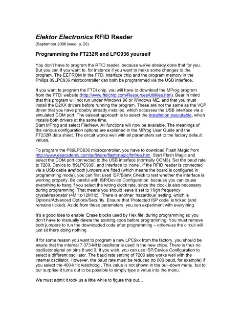
<strong>Elektor</strong> <strong>Electronics</strong> <strong>RFID</strong> <strong>Reader</strong><br />
(September 2006 issue, p. 26)<br />
Programming the FT232R and LPC936 yourself<br />
You don’t have to program the <strong>RFID</strong> reader, because we’ve already done that for you.<br />
But you can if you want to, for instance if you want to make s<strong>om</strong>e changes to the<br />
program. The EEPROM in the FTDI interface chip and the program memory in the<br />
Philips 89LPC936 microcontroller can both be programmed via the USB interface.<br />
If you want to program the FTDI chip, you will have to download the MProg program<br />
fr<strong>om</strong> the FTDI website (http://www.ftdichip.c<strong>om</strong>/Resources/Utilities.htm). Bear in mind<br />
that this program will not run under Windows 98 or Windows ME, and that you must<br />
install the D2XX drivers before running the program. These are not the same as the VCP<br />
driver that you have probably already installed, which accesses the USB interface via a<br />
simulated COM port. The easiest approach is to select the installation executable, which<br />
installs both drivers at the same time.<br />
Start MProg and select File/New. All functions will now be available. The meanings of<br />
the various configuration options are explained in the MProg User Guide and the<br />
FT232R data sheet. The circuit works well with all parameters set to the factory default<br />
values.<br />
To program the P89LPC936 microcontroller, you have to download Flash Magic fr<strong>om</strong><br />
http://www.esacademy.c<strong>om</strong>/software/flashmagic/fmfree.htm. Start Flash Magic and<br />
select the COM port connected to the USB interface (normally COM3). Set the baud rate<br />
to 7200, Device to ‘89LPC936’, and Interface to ‘none’. If the <strong>RFID</strong> reader is connected<br />
via a USB cable and both jumpers are fitted (which means the board is configured in<br />
programming mode), you can first used ISP/Blank Check to test whether the interface is<br />
working properly. Be careful with ISP/Device Configuration, because you can cause<br />
everything to hang if you select the wrong clock rate, since the clock is also necessary<br />
during programming. That means you should leave it set to ‘High frequency<br />
crystal/resonator (4MHz-12MHz)’. There is another ‘hazardous’ setting, which is<br />
Options/Advanced Options/Security. Ensure that ‘Protected ISP code’ is ticked (and<br />
remains ticked). Aside fr<strong>om</strong> these parameters, you can experiment with everything.<br />
It’s a good idea to enable ‘Erase blocks used by Hex file’ during programming so you<br />
don’t have to manually delete the existing code before programming. You must remove<br />
both jumpers to run the downloaded code after programming – otherwise the circuit will<br />
just sit there doing nothing.<br />
If for s<strong>om</strong>e reason you want to program a new LPC9xx fr<strong>om</strong> the factory, you should be<br />
aware that the internal 7.373-MHz oscillator is used in the new chips. There is thus no<br />
oscillator signal on pins 8 and 9. If you wish, you can use ISP/Device Configuration to<br />
select a different oscillator. The baud rate setting of 7200 also works well with the<br />
internal oscillator. However, the baud rate must be reduced (to 600 baud, for example) if<br />
you select the 400-kHz watchdog . This value is not shown in the pull-down menu, but to<br />
our surprise it turns out to be possible to simply type a value into the menu.<br />
We must admit it took us a little while to figure this out…
Table<br />
<strong>Reader</strong> and card c<strong>om</strong>mands for Mifare UltraLite<br />
<strong>Reader</strong> functions<br />
void MFRc522Init(void);<br />
int <strong>Reader</strong>RfReset(unsigned int msec);<br />
Card activation<br />
int ISO14443_Request(unsigned char req_cmd, unsigned char *atq);<br />
int ISO14443_Anticoll (unsigned char bcnt, unsigned char *snr);<br />
int ISO14443_Select(unsigned char *snr, unsigned char *sak);<br />
int ISO14443_HALTA(void);<br />
Mifare UltraLight memory manipulation<br />
int MifareRead(unsigned char addr, unsigned char *data);<br />
int MifareULWrite(unsigned char addr, unsigned char *data);<br />
Listing<br />
(060132-1)<br />
Code for card activation and reading data blocks fr<strong>om</strong> a Mifare ® UltraLite card. The data blocks<br />
are output afterwards via the serial interface.<br />
while(1)<br />
{<br />
status = ISO14443_Request(WUPA, &bATQ);<br />
if(status != STATUS_SUCCESS)<br />
continue;<br />
status = ISO14443_Anticoll(Level1,0,&abSNR[0]);<br />
if(status != STATUS_SUCCESS)<br />
continue;<br />
status = ISO14443_Select(Level1, &abSNR[0], &bSAK);<br />
if(status != STATUS_SUCCESS)<br />
continue;<br />
// Check if UID is c<strong>om</strong>plete<br />
if((bSAK & 0x04) == 0x04)<br />
{<br />
// UID not c<strong>om</strong>plete<br />
status = ISO14443_Anticoll(Level2,0,&abSNR[4]);<br />
if(status != STATUS_SUCCESS)<br />
continue;<br />
}<br />
status = ISO14443_Select(Level2, &abSNR[4], &bSAK);<br />
if(status != STATUS_SUCCESS)<br />
continue;<br />
// Read UltraLight Block 0..3<br />
status = Read(0,abDataBuffer);

