IP-W " ~ - ` - JUWEL - Forschungszentrum Jülich
IP-W " ~ - ` - JUWEL - Forschungszentrum Jülich
IP-W " ~ - ` - JUWEL - Forschungszentrum Jülich

Create successful ePaper yourself
Turn your PDF publications into a flip-book with our unique Google optimized e-Paper software.
P-W<br />
"<br />
~<br />
-<br />
~<br />
`<br />
%I<br />
, 0 .;<br />
, ./<br />
1~<br />
'`~'<br />
-<br />
-~~<br />
_~ .
Schriften des <strong>Forschungszentrum</strong>s <strong>Jülich</strong><br />
Reihe Umwelt/Environment Band/Volume 52
<strong>Forschungszentrum</strong> <strong>Jülich</strong> GmbH<br />
Programmgruppe Systemforschung und Technologische Entwicklung<br />
Institut für Chemie und Dynamik der Geosphäre IV: Agrosphäre<br />
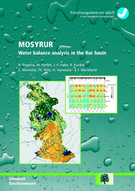
MOSYRUR<br />
Water balance analysis in the Rur basin<br />
Heye Bogena, Michael Herbst, Jürgen-Friedrich Hake,<br />
Ralf Kunkel, Carsten Montzka, Thomas Pütz,<br />
Harry Vereecken, Frank Wendland<br />
Schriften des <strong>Forschungszentrum</strong>s <strong>Jülich</strong><br />
Reihe Umwelt/Environment Band/Volume 52<br />
ISSN 1433-5530 ISBN 3-89336-385-8
Bibliographic information published by Die Deutsche Bibliothek .<br />
Die Deutsche Bibliothek lists this publication in the Deutsche<br />
Nationalbibliografie ; detailed bibliographic data are available in the<br />
Internet .<br />
Publisher and <strong>Forschungszentrum</strong> <strong>Jülich</strong> GmbH<br />
Distributor : Zentralbibliothek<br />
52425 <strong>Jülich</strong><br />
Phone +49 (0) 24 61 61-53 68 Fax +49 (0) 24 61 61-6103<br />
e-mail : zb-publikation@fz-juelich .de<br />
Internet : http ://www.fz-juelich.de/zb<br />
Cover Design : Grafische Betriebe, <strong>Forschungszentrum</strong> <strong>Jülich</strong> GmbH<br />
Printer : Grafische Betriebe, <strong>Forschungszentrum</strong> <strong>Jülich</strong> GmbH<br />
Copyright :<br />
<strong>Forschungszentrum</strong> <strong>Jülich</strong> 2005<br />
Schriften des <strong>Forschungszentrum</strong>s <strong>Jülich</strong><br />
Reihe Umwelt/Environment Band/Volume 52<br />
ISSN 1433-5530<br />
ISBN 3-89336-385-8<br />
Neither this book nor any part of it may be reproduced or transmitted in any form or by any<br />
means, electronic or mechanical, including photocopying, microfilming, and recording, or by any<br />
information storage and retrieval system, without permission in writing from the publisher.
Table of Contents
1 Introduction . . . . . . . . . . . . . . . . . . . . . . . . . . . . . . . . . . . . . . . . . . . . . . . . . . . . . . . . . . . . . . . . . . . . . . . . . . . . . . . . 5<br />
1 .1 Challenges for the management of water resources . . . . . . . . . . . . . . . . . . . . . . . . . . . 7<br />
1 .2 Project goals . . . . . . . . . . . . . . . . . . . . . . . . . . . . . . . . . . . . . . . . . . . . . . . . . . . . . . . . . . . . . . . . . . . . . . . . . . . . . . . . . . . . . . . . 8<br />
1 .3 Areas of investigation . . . . . . . . . . . . . . . . . . . . . . . . . . . . . . . . . . . . . . . . . . . . . . . . . . . . . . . . . . . . . . . . . . . . . . . . . . 9<br />
2 Description of the models . . . . . . . . . . . . . . . . . . . . . . . . . . . . . . . . . . . . . . . . . . . . . . . . . . . . . . . 11<br />
2 .1 The TRACE Model . . . . . . . . . . . . . . . . . . . . . . . . . . . . . . . . . . . . . . . . . . . . . . . . . . . . . . . . . . . . . . . . . . . . . . . . . . . . 13<br />
2.1 .1 Geometry . . . . . . . . . . . . . . . . . . . . . . . . . . . . . . . . . . . . . . . . . . . . . . . . . . . . . . . . . . . . . . . . . . . . . . . . . . . . . . . . 13<br />
2.1.2 Numerical solution . . . . . . . . . . . . . . . . . . . . . . . . . . . . . . . . . . . . . . . . . . . . . . . . . . . . . . . . . . . . . . . . . . . 14<br />
2.1.3 Boundary conditions . . . . . . . . . . . . . . . . . . . . . . . . . . . . . . . . . . . . . . . . . . . . . . . . . . . . . . . . . . . . . . . . 14<br />
2.1.4 Soil hydraulic properties . . . . . . . . . . . . . . . . . . . . . . . . . . . . . . . . . . . . . . . . . . . . . . . . . . . . . . . . . . 15<br />
2.1.5 The plant module SUCROS . . . . . . . . . . . . . . . . . . . . . . . . . . . . . . . . . . . . . . . . . . . . . . . . . . . . 16<br />
2 .2 The GROWA Model . . . . . . . . . . . . . . . . . . . . . . . . . . . . . . . . . . . . . . . . . . . . . . . . . . . . . . . . . . . . . . . . . . . . . . . . . . 20<br />
2.2 .1 Plane unpaved sites with deep water tables . . . . . . . . . . . . . . . . . . . . . . . . . . . 20<br />
2.2.2 High relief terrains . . . . . . . . . . . . . . . . . . . . . . . . . . . . . . . . . . . . . . . . . . . . . . . . . . . . . . . . . . . . . . . . . . . 22<br />
2.2.3 Groundwater-affected sites . . . . . . . . . . . . . . . . . . . . . . . . . . . . . . . . . . . . . . . . . . . . . . . . . . . . . 23<br />
2.2.4 Urban regions . . . . . . . . . . . . . . . . . . . . . . . . . . . . . . . . . . . . . . . . . . . . . . . . . . . . . . . . . . . . . . . . . . . . . . . . . . 25<br />
2.2.5 Deriving the groundwater recharge . . . . . . . . . . . . . . . . . . . . . . . . . . . . . . . . . . . . . . . . . 27<br />
2.2.6 Determining the BFI values from gauge data . . . . . . . . . . . . . . . . . . . . . . . . . . 27<br />
2.2.7 Identification of runoff-effective site conditions . . . . . . . . . . . . . . . . . . . . . . . . 29<br />
2.2.8 Attribution of area-differentiated BFI values . . . . . . . . . . . . . . . . . . . . . . . . . . . . 31<br />
3 Data preparation and regionalization . . . . . . . . . . . . . . . . . . . . . . . . . . . . . . . . . . . . . 35<br />
3 .1 Microscale . . . . . . . . . . . . . . . . . . . . . . . . . . . . . . . . . . . . . . . . . . . . . . . . . . . . . . . . . . . . . . . . . . . . . . . . . . . . . . . . . . . . . . . . .37<br />
3.1 .1 Material and Methods . . . . . . . . . . . . . . . . . . . . . . . . . . . . . . . . . . . . . . . . . . . . . . . . . . . . . . . . . . . . . . 37<br />
3.1.2 Results . . . . . . . . . . . . . . . . . . . . . . . . . . . . . . . . . . . . . . . . . . . . . . . . . . . . . . . . . . . . . . . . . . . . . . . . . . . . . . . . . . . . 40<br />
3 .2 Macroscale . . . . . . . . . . . . . . . . . . . . . . . . . . . . . . . . . . . . . . . . . . . . . . . . . . . . . . . . . . . . . . . . . . . . . . . . . . . . . . . . . . . . . . . .45<br />
3.2 .1 Climatic data bases . . . . . . . . . . . . . . . . . . . . . . . . . . . . . . . . . . . . . . . . . . . . . . . . . . . . . . . . . . . . . . . . . 46<br />
3.2.2 Landcover data . . . . . . . . . . . . . . . . . . . . . . . . . . . . . . . . . . . . . . . . . . . . . . . . . . . . . . . . . . . . . . . . . . . . . . . 51<br />
3.2.3 Soil data . . . . . . . . . . . . . . . . . . . . . . . . . . . . . . . . . . . . . . . . . . . . . . . . . . . . . . . . . . . . . . . . . . . . . . . . . . . . . . . . . . 55<br />
3.2.4 Hydrogeological data base . . . . . . . . . . . . . . . . . . . . . . . . . . . . . . . . . . . . . . . . . . . . . . . . . . . . . . 66<br />
3.2.5 Topographic data . . . . . . . . . . . . . . . . . . . . . . . . . . . . . . . . . . . . . . . . . . . . . . . . . . . . . . . . . . . . . . . . . . . . 71<br />
3.2.6 Discharge data . . . . . . . . . . . . . . . . . . . . . . . . . . . . . . . . . . . . . . . . . . . . . . . . . . . . . . . . . . . . . . . . . . . . . . . . 74
4 Model results . . . . . . . . . . . . . . . . . . . . . . . . . . . . . . . . . . . . . . . . . . . . . . . . . . . . . . . . . . . . . . . . . . . . . . . . . . . .77<br />
4.1 Microscale . . . . . . . . . . . . . . . . . . . . . . . . . . . . . . . . . . . . . . . . . . . . . . . . . . . . . . . . . . . . . . . . . . . . . . . . . . . . . . . . . . . . . . . . .79<br />
4.2 Macroscale . . . . . . . . . . . . . . . . . . . . . . . . . . . . . . . . . . . . . . . . . . . . . . . . . . . . . . . . . . . . . . . . . . . . . . . . . . . . . . . . . . . . . . . .81<br />
4.2 .1 Actual evapotranspiration . . . . . . . . . . . . . . . . . . . . . . . . . . . . . . . . . . . . . . . . . . . . . . . . . . . . . . . . 83<br />
4.2.2 Total runoff. . . . . . . . . . . . . . . . . . . . . . . . . . . . . . . . . . . . . . . . . . . . . . . . . . . . . . . . . . . . . . . . . . . . . . . . . . . . . . 86<br />
4.2.3 Groundwater recharge . . . . . . . . . . . . . . . . . . . . . . . . . . . . . . . . . . . . . . . . . . . . . . . . . . . . . . . . . . . . 88<br />
4.2.4 Direct runoff. . . . . . . . . . . . . . . . . . . . . . . . . . . . . . . . . . . . . . . . . . . . . . . . . . . . . . . . . . . . . . . . . . . . . . . . . . . . . 91<br />
4.2.5 Predominating runoff components . . . . . . . . . . . . . . . . . . . . . . . . . . . . . . . . . . . . . . . . . . 94<br />
5 Model Validation . . . . . . . . . . . . . . . . . . . . . . . . . . . . . . . . . . . . . . . . . . . . . . . . . . . . . . . . . . . . . . . . . . . . . . 97<br />
5.1 Microscale . . . . . . . . . . . . . . . . . . . . . . . . . . . . . . . . . . . . . . . . . . . . . . . . . . . . . . . . . . . . . . . . . . . . . . . . . . . . . . . . . . . . . . . . .99<br />
5.1 .1 Measurements and model input . . . . . . . . . . . . . . . . . . . . . . . . . . . . . . . . . . . . . . . . . . . . . . 99<br />
5.1.2 Lysimeter experiment . . . . . . . . . . . . . . . . . . . . . . . . . . . . . . . . . . . . . . . . . . . . . . . . . . . . . . . . . . . . 101<br />
5.1.3 Field experiment . . . . . . . . . . . . . . . . . . . . . . . . . . . . . . . . . . . . . . . . . . . . . . . . . . . . . . . . . . . . . . . . . . . . 105<br />
5.2 Macroscale . . . . . . . . . . . . . . . . . . . . . . . . . . . . . . . . . . . . . . . . . . . . . . . . . . . . . . . . . . . . . . . . . . . . . . . . . . . . . . . . . . . . . .106<br />
5.2 .1 Total runoff. . . . . . . . . . . . . . . . . . . . . . . . . . . . . . . . . . . . . . . . . . . . . . . . . . . . . . . . . . . . . . . . . . . . . . . . . . . . 110<br />
5.2.2 Groundwater recharge and direct runoff. . . . . . . . . . . . . . . . . . . . . . . . . . . . . . . . 111<br />
5.3 Analysis of scale effects . . . . . . . . . . . . . . . . . . . . . . . . . . . . . . . . . . . . . . . . . . . . . . . . . . . . . . . . . . . . . . . . . . 114<br />
5.3 .1 Procedure . . . . . . . . . . . . . . . . . . . . . . . . . . . . . . . . . . . . . . . . . . . . . . . . . . . . . . . . . . . . . . . . . . . . . . . . . . . . . . 114<br />
5.3.2 Results . . . . . . . . . . . . . . . . . . . . . . . . . . . . . . . . . . . . . . . . . . . . . . . . . . . . . . . . . . . . . . . . . . . . . . . . . . . . . . . . . . 115<br />
6 Disaggregation of nutrient balances . . . . . . . . . . . . . . . . . . . . . . . . . . . . . . . . . . . . 121<br />
6.1 Introduction and Objectives . . . . . . . . . . . . . . . . . . . . . . . . . . . . . . . . . . . . . . . . . . . . . . . . . . . . . . . . . . . . . 123<br />
6.2 Database . . . . . . . . . . . . . . . . . . . . . . . . . . . . . . . . . . . . . . . . . . . . . . . . . . . . . . . . . . . . . . . . . . . . . . . . . . . . . . . . . . . . . . . . .123<br />
6.3 Image Processing . . . . . . . . . . . . . . . . . . . . . . . . . . . . . . . . . . . . . . . . . . . . . . . . . . . . . . . . . . . . . . . . . . . . . . . . . . . . 124<br />
6.3 .1 Preprocessing . . . . . . . . . . . . . . . . . . . . . . . . . . . . . . . . . . . . . . . . . . . . . . . . . . . . . . . . . . . . . . . . . . . . . . . 124<br />
6.3.2 Classification . . . . . . . . . . . . . . . . . . . . . . . . . . . . . . . . . . . . . . . . . . . . . . . . . . . . . . . . . . . . . . . . . . . . . . . . . 126<br />
6.3.3 Accuracy assessment and classification results . . . . . . . . . . . . . . . . . . . . 131<br />
6.3.4 Disaggregation . . . . . . . . . . . . . . . . . . . . . . . . . . . . . . . . . . . . . . . . . . . . . . . . . . . . . . . . . . . . . . . . . . . . . . 135<br />
6.4 Conclusion . . . . . . . . . . . . . . . . . . . . . . . . . . . . . . . . . . . . . . . . . . . . . . . . . . . . . . . . . . . . . . . . . . . . . . . . . . . . . . . . . . . . . . .138<br />
7 Summary . . . . . . . . . . . . . . . . . . . . . . . . . . . . . . . . . . . . . . . . . . . . . . . . . . . . . . . . . . . . . . . . . . . . . . . . . . . . . . . .141<br />
8 References . . . . . . . . . . . . . . . . . . . . . . . . . . . . . . . . . . . . . . . . . . . . . . . . . . . . . . . . . . . . . . . . . . . . . . . . . . . . .147
Introduction
1 .1 Challenges for the management of water resources<br />
Dependent on the regional hydrogeological conditions water resources management<br />
practices in the Rur basin differ greatly . The upland region is characterized<br />
by solid rock strata of low permeability . Therefore the groundwater<br />
aquifers are limited and runoff generation occurs mainly through direct runoff .<br />
Consequently the water resources in this part of the Rur basin are managed<br />
by reservoirs . In all, there are ten reservoirs in the catchment area of the Rur,<br />
which are used for drinking water supply, energy generation and flood control .<br />
In the adjacent flatland region to the north there are abundant loose rock aquifers,<br />
with high groundwater recharge rates . Accordingly, these aquifers are<br />
subject to an intensive groundwater withdrawal for drinking and service water<br />
purposes . For example, major amounts of service water are extracted in the<br />
Heinsberg region and along the River Rur between Düren and Mich . Additionally,<br />
sumping wells for keeping open-cast lignite mines dry are also maintained<br />
(e .g . the open-cast pit Inden) .<br />
Quantitatively, a clear resources surplus is available in total in the Rur catchment<br />
area despite numerous water uses and the sumping measures . The local<br />
availability of water for industrial and ecological purposes, however, is problematic<br />
. Groundwater-dependent biotopes and agricultural areas are locally<br />
affected by groundwater lowering due to extraction for drinking water supply .<br />
The sumping measures for keeping the open-pit mines dry have an extensive<br />
effect . For example, they have led to translocations of underground catchment<br />
boundaries and thus to a translocation of protective zones .<br />
Qualitatively, the groundwater and the surface waters are affected by diffuse<br />
inputs of agricultural activities (e .g . plant nutrients, pesticides) and point<br />
source emissions from landfills and abandoned contaminated sites . In addition,<br />
the groundwater is linearly polluted due to leaky draining channels . In<br />
order to avoid cost-intensive purification measures, this has led, for example,<br />
to groundwater extractions from deeper, still unpolluted groundwater storeys in<br />
the region of the Rur block . However, due to the open-cast lignite mines, the<br />
groundwater quality of the deeper aquifers itself has been affected in some<br />
areas due to groundwater acidification induced by pyrite oxidation and because<br />
of a rise of strongly mineralized deep-circulating waters .<br />
The above problems have been recognized by the water management authorities<br />
. In the different subareas of the river basin, local measures are therefore
implemented in order to minimize the anthropogenic influence . Nearly all water<br />
utilities with nitrate problems, for example, have entered into cooperations with<br />
agriculture . The stock of aquatic biotopes along the receiving waters is maintained<br />
e.g . by water-holding measures . Integrated sustainable water management<br />
concepts, however, only exist rudimentarily and for small subregions in<br />
most cases .<br />
1 .2 Project goals<br />
The research project "Development of an integrative model system for the<br />
sustainable water management in the catchment of the River Rur (MO-<br />
SYRUR)" was initiated by the Institute of Chemistry and Dynamics of the Geosphere,<br />
Department Agrosphere (ICG-IV) and the Program Group Systems<br />
Analysis and Technology Evaluation (STE) of the Research Centre <strong>Jülich</strong> .<br />
The aim of the research project planned by ICG-IV and STE is to develop an<br />
implementation-oriented integrated modelling system to facilitate a sustainable<br />
management of the water resources in the Rur basin . This is to be accomplished<br />
on the basis of a quantitative and qualitative analysis of the status of<br />
water resources and of the current water uses in the Rur basin .<br />
An essential objective of the project is the water balance modelling on different<br />
scale levels to evaluate measures for the quantitative management of water<br />
resources under the conditions prevailing in the Rur basin . This includes process-oriented<br />
studies and modelling in small representative test areas and also<br />
methods for the large-area GIS-based water balance estimations in the river<br />
basin .<br />
ICG-IV and STE have already gathered a long-standing experience on these<br />
topics . A particular scientific challenge in this context is the development of<br />
upscaling and downscaling methods for the models for parameterizing and<br />
characterizing the water balance and transport of substances in landscape<br />
units and geological structures . Additionally, modern technologies of remote<br />
sensing and digital image processing can be applied in order to achieve high<br />
resolution landcover information as a basis for the hydrological modelling .<br />
This report summarizes the results of the research activities of the first project<br />
phase (2002-2004), which has been focused on the analysis of the quantitative<br />
status of the water resources in Rur basin and the water balance at different<br />
scales .
1 .3 Areas of investigation<br />
The areas of investigation have been chosen according to the existing instruments<br />
and modelling systems developed and applied at FZJ, i .e . at ICG-IV<br />
and STE, for modelling water fluxes in soil and groundwater systems at different<br />
scale levels . Map 1 shows the investigated subareas of the MOSYRUR<br />
project .<br />
The entire catchment area of the River Rur with a total area of 2354 km2<br />
represents the macroscale . It is situated in the Lower Rhine Embayment,<br />
which is a geological subsidence structure located in North Rhine-Westphalia<br />
(Germany) . About 157 km2 (6 .7 %) of the Rur basin is in Belgium and about<br />
108 km 2 (4 .6 %) on Dutch territory . A detailed description of the Rur catchment<br />
concerning land use as well as climatological, pedological and geological<br />
characteristics is given in Chapter 3 .2 .<br />
The studies relating to the entire catchment area are performed at STE . For<br />
this purpose, modelling instruments developed at STE for application in macroscale<br />
water catchment areas (between approx . 1,000 km 2 and more than<br />
100,000 km2 ) will be used, with which water resources, area drainage and the<br />
transport of diffuse pollutants (e .g . excess fertilizers from agricultural land use)<br />
can be modelled and analysed . The modelling instruments were successfully<br />
used in past years in various national and international research projects (e .g .<br />
in the project REGLUD funded in the framework of the BMBF research priority<br />
"river basin management" and the EU project EUROCAT) .<br />
A subarea of the middle Rur, the test area `Zwischenscholle', which is about<br />
20 km2 in size, was selected as the microscale test region (see Map 1) . For<br />
this subarea, the percolation to the groundwater and the water transport in the<br />
aquifer was modelled three-dimensionally and with a high time resolution using<br />
the TRACE model (Herbst et al ., 2003) .<br />
These models will be set up in parallel for the entire region and for subregions .<br />
By means of a comparison of the input data and the model results obtained for<br />
the entire catchment area with those of individual subregions it will be possible,<br />
as part of the project, to specify conclusions concerning the validity of the<br />
large-area models and the accuracy of the simulation results for the subregions<br />
.
--- National border<br />
Cities<br />
h~ Waterbodies<br />
Streams<br />
Mapediting: Dr . H . Bogen.; Febaary 2004<br />
Data base : Research Centre <strong>Jülich</strong> ! S1E :<br />
Base map MOSYRUR<br />
Map 1 : The investigated subareas in the MOSYRUR project .<br />
10<br />
Subareas of the<br />
MOSYRUR project<br />
Research Centre <strong>Jülich</strong> GnrbH<br />
sysem~ anNUlysrs ~ann necnnoiayy~[-~omauon
Description of the<br />
models
2.1 The TRACE Model<br />
TRACE (Vereecken et al . 1994) is a massive-parallel computer code developed<br />
to solve water flow in large scale soil-groundwater systems . It is based<br />
on the 3DFEMWATER code (Yeh, 1987) . The model has mainly been used to<br />
generate stochastic flow fields in order to test stochastic theories of solute<br />
transport (Neuendorf 1986, D6ring 1997, Schwarze et al . 2001, Englert 2003) .<br />
In the framework of the PEGASE project, the model was applied to agricultural<br />
soils with groundwater influence . Therefore changes to the numerical solution,<br />
the upper boundary conditions and handling of soil hydraulic properties were<br />
necessary to properly compute the unsaturated-saturated flow of water in<br />
cropped soils . To calculate plant growth the plant module SUCROS (Spitters<br />
et al . 1988) was integrated in the TRACE model . This model allows to calculate<br />
the LAI and rooting depth of agricultural crops, which are needed for the<br />
calculation of the actual evapotranspiration . The core of TRACE is the following<br />
modified version of the Richards equation :<br />
ah(s ) = a k a(h(s ) +z) ae<br />
h -<br />
(x(s, h) - ) + S(s, t) with Fh = + Sh<br />
at<br />
as as<br />
ah<br />
2.1 .1 Geometry<br />
The equation given in the introduction is solved using Galerkin-type finite elements<br />
. The flow domain is represented by isoparameteric hexahedrons . Every<br />
element consists of eight corner nodes and six sides . The element can be<br />
distorted (see Fig . 7 right hand side) but the nodes of every side have to be<br />
located on the same plane .<br />
Fig . 1 : Two examples of geometry .<br />
1 3
In order to comply with specific requirements of GIS (e .g . regular grid) and to<br />
provide rapid access to node indices the number of nodes in one direction of<br />
space is kept constant, e .g . nx and ny elements in x and y-direction respec-<br />
tively .<br />
2 .1.2 Numerical solution<br />
In order to improve the numerical solution for unsaturated conditions, several<br />
modifications were carried out . TRACE calculates the 3-dimensional unsatu-<br />
rated/saturated water flow in porous media with a modified Picard-iteration<br />
scheme (Celia et al . 1990) which is applied in combination with a precondi-<br />
tioned conjugate gradient method in order to solve the modified version of the<br />
Richards' equation numerically . It was necessary to improve the mass balance<br />
in the unsaturated zone . Thus the approach of Celia et al . was implemented in<br />
combination with a mass lumping approach and a modified convergence crite-<br />
rion according to Huang et al . (1996) . Furthermore a convergence dependent<br />
dynamic relaxation time factor was introduced to improve numerical stability<br />
and computation speed .<br />
2 .1.3 Boundary conditions<br />
A special type of boundary condition relevant for the regional scale application<br />
is the `global Dirichlet boundary condition' . This boundary condition can only<br />
be applied to the vertical sides of the flow domain . For every vertical node<br />
column of the vertical sides the groundwater level GL [L] must be given . For<br />
this vertical column of nodes all unsaturated nodes are set at a no-flow<br />
boundary (Cauchy, with qc=0, see Tab . 1) .<br />
Tab . 1 : Available boundary conditions in TRACE<br />
1 4<br />
Boundary condition<br />
Total flux (Cauchy)<br />
Flux (Neumann)<br />
Head (Dirichlet)<br />
Seepage face (lysimeter)<br />
Definition<br />
q, =-K-VH<br />
q, =-K-Vh<br />
given h<br />
q = 0 for h < 0 or Dirichlet with h = 0<br />
For the saturated nodes hydrostatic equilibrium is assumed and pressure head<br />
h is calculated from GL-z, where z is the local z-coordinate . Total head H [L] is
equal to h + z . Another special type of boundary condition was implemented<br />
for the atmospheric boundary . This boundary condition is described by a vari-<br />
able type boundary . Depending on atmospheric conditions either a Dirichlet or<br />
Cauchy boundary conditions is prevailing . The change between both types is<br />
based on two pre-set pressure heads hmin [L] and hcon [L] need to be given .<br />
The former is set when soil becomes to dry to sustain the potential evapora-<br />
tion and the latter one is used to describe the process of ponding . During infil-<br />
tration a flow boundary condition (Cauchy) is applied until hcon is reached .<br />
Then TRACE switches to a Dirichlet boundary condition and the pressure<br />
head at the soil surface is set to hcon (e .g . 1 cm) . The infiltration excess is re-<br />
moved at the next timestep . A similar concept is applied for the reduction of<br />
evaporation . A flux boundary is applied until hrnin is reached (e .g . 10 -4 cm) . At<br />
this point TRACE switches to a fixed head boundary condition set to hm ;n .<br />
2.1.4 Soil hydraulic properties<br />
Two approaches were implemented, which describe the soil water retention<br />
and the unsaturated hydraulic conductivity . The first one is the very commonly<br />
used approach of Mualem/Van Genuchten (Van Genuchten 1980) :<br />
e(h) = 0,+ e' -e' and K(h) --K,<br />
(1- (a h mn ~<br />
1+(ah~~<br />
(I +(ahy ~'<br />
where 0 denotes the water content [L 3 L -3 ], h is the pressure head [L], Or is the<br />
residual water content [L3 L-3], 6 s is the water content at saturation [L 3 L-3 ], a is<br />
the inverse of the bubbling pressure [L- '], KS [L T -'] is the saturated hydraulic<br />
conductivity and m and n are dimensionless shape parameters . The following<br />
equation yields 0010h, which is necessary to calculate the specific water<br />
capacity :<br />
C(h) - (er - e,,)mnanh"-~<br />
(I + (a h ~ rt+i<br />
For the second approach the parameter m of the retention function of Van<br />
Genuchten is set equal to 1 . Thus the closed analytical expression of the<br />
Mualem/van Genuchten approach for the K(h) function is lost . Instead the un-<br />
saturated hydraulic conductivity function of Gardner (1958) was applied :<br />
-<br />
1 5
1 6<br />
B(h) = 0, +<br />
- r ,<br />
1+(ah)<br />
Here two new parameters b (cm-) and c (-) are introduced . The derivative of 6<br />
against h is given by :<br />
= (0,, - 8,)na"h<br />
" -'<br />
C(h)<br />
and K(h) =<br />
2 .1.5 The plant module SUCROS<br />
In order to take plant related processes into account the SUCROS module<br />
(Spitters 1988), implemented in WAVE was adapted to TRACE. During the<br />
implementation several modifications and extensions were necessary to link<br />
SUCROS and TRACE, mainly because TRACE is a 3-d model applicable to<br />
regional scale problems while WAVE was designed for local scale 1-d problems<br />
. In the following the basic concepts of SUCROS are explained in connection<br />
to the modifications during the implementation in TRACE .<br />
In contrast to most of the plant modules in soil water models SUCROS calculates<br />
the leaf area index (LAI) . In SUCROS the green leaf area index (LAlgreen)<br />
is calculated from the biomass development, which is a function of the plant<br />
specific C0 2 assimilation and photosynthetic active radiation . Details on the<br />
basic principles of crop growth simulation can be found in the SUCROS manual<br />
(Spitters et al . 1988) .<br />
The main purpose of a plant module is to describe root extraction of water<br />
from the soil by plants, the process of interception loss at the canopy and to<br />
estimate the amount of potential evaporation from the soil surface . The first<br />
step is to calculate the potential evapotranspiration for the reference grass<br />
cover ETpot [L T- '] , e.g . with the approach of Penman/Monteith . In order to<br />
describe the seasonal deviation of the potential evapotranspiration of crops to<br />
the one of the grass reference the approach of Doorenbos and Pruitt (1977) is<br />
applied (see also Fig . 2) :<br />
ET,jop = ETp,Kc (6)<br />
where Et,ro p [L T - '] is the plant specific potential evapotranspiration and K, [-] is<br />
the crop conversion factor . The leaf area index LAI [L 2 L-2 ] is used to separate<br />
potential evaporation and transpiration .
Y<br />
ö<br />
Ü<br />
0 .8<br />
ö<br />
0 .6 -<br />
U<br />
0 .4<br />
0 .2<br />
0 .0<br />
90 1 0 110 1 0 170<br />
Emergence Ground Full Maturity Harvest<br />
cover ground<br />
h2 =<br />
her<br />
h2h<br />
where the threshold values of Tp are given in mm d - ' . Then the reduction factor<br />
is calculated according to :<br />
1 8<br />
a(h) =<br />
= ge<br />
1-0e<br />
n<br />
h2h + 0. 0.4<br />
p 021 - h2h) for<br />
i=1<br />
ho -h<br />
ho - h,<br />
1<br />
h, -h<br />
10 k'<br />
Root extraction in the element e Se [T - '] is calculated from the actual transpiration<br />
Ta [L T'], the corresponding surface area AT [L2 ], the normalized root density<br />
we [-] and the volume of the element Ve [L3 ] .<br />
V e<br />
ge,i<br />
with<br />
ho
No =Np +Ni (13)<br />
The overflowing bucket is filled with precipitation until the maximum is reached<br />
and the fraction above the maximum is taken as the fraction reaching the soil<br />
surface . This maximum is calculated from the LAI [-] :<br />
Si = 0,2LAI (14)<br />
where S ; is the interception capacity [L], equivalent to the maximum volume of<br />
interception . Water is taken out of the interception storage by evaporation :<br />
E, = (ET,,,p -Ep) S` (15 )<br />
where Ei [L] is the amount of evaporation from intercept for the particular time<br />
step, and Ci [L] is the interception storage for that time step . Then the amount<br />
of interception can be estimated from :<br />
No = 0<br />
-C, for Si - C (16)<br />
i < No<br />
Si - Ci > No<br />
Alternatively the empirical approach of Hoyningen-Huene (1983) for interception<br />
can be applied to time steps equal to or larger than one day :<br />
=-0.42+0 .245N o +0.2LAI+0.0271NoLAI-0.0111N02 -0.0109LAI 2 (18)<br />
In order to account for water stress on dry matter growth rate per unit area Rm<br />
[M L-2 T- '], the dry matter growth rate per unit area Rrn [M L-2 T - '] calculated<br />
from the radiation conditions is scaled with the ratio between actual and potential<br />
transpiration :<br />
A special module for perennial vegetation like forest was developed . Here the<br />
basic assumption is, that the same seasonal behaviour of the plant appears<br />
every year . The key parameters LAI, rooting depth and the Kc value must be<br />
(19)<br />
1 9
given as a function of the day of the year . A linear interpolation is applied for<br />
times between the given parameter values .<br />
2.2 The GROWA Model<br />
The raster based GROWA model consists of several modules for determining<br />
the long-term annual averages of the main water balance components (actual<br />
evapotranspiration, total discharge, direct runoff and groundwater recharge) .<br />
The basis for calculating the total runoff level is the water balance equation,<br />
according to which the annual total runoff level on a long-term average is<br />
given by the difference between the mean annual precipitation and the mean<br />
annual actual evapotranspiration . In contrast to precipitation being measured<br />
directly at gauging stations, the actual evapotranspiration must be determined<br />
by modelling approaches .<br />
2.2.1 Plane unpaved sites with deep water tables<br />
The method of Renger & Wessolek (1996) allows a calculation of the annual<br />
actual evapotranspiration (ETaRw) for plane unpaved sites with deep water<br />
tables (Eq . 20) .<br />
20<br />
ETa RW = a - P,,i + b - P,,u + c - log(WR1 )+ d - ET,, + e (20)<br />
ETaRw : Actual evapotranspiration according to Renger & Wessolek [mm/a]<br />
a,b,c,d,e : Land use specific coefficients [-]<br />
P" ;, PS : Winter and summer precipitation [mm/a]<br />
WP/<br />
: Plant available soil water content [mm]<br />
ET. : Potential evapotranspiration [mm/a]<br />
The landcover enters in Eq . 20 via the land use-specific coefficients of regression<br />
a . . . e, which are listed in Tab . 2 . For arable land, grassland and coniferous<br />
forest the regression constants according to Renger & Wessolek (1996)<br />
are used . For deciduous forest constants according to Renger & Strebel<br />
(1980) are used . It has to be noted that in this case, instead of the half-year<br />
levels of precipitation, only the mean annual precipitation is considered and<br />
that the plant available volume of soil water is not taken into account . In order<br />
to determine the mean actual evapotranspiration of vegetation-free areas, a<br />
simple approach of Proksch (1990) is applied . This method was derived from
lysimeter results for different soils (DVWK, 1996) and takes only the annual<br />
level of precipitation into account .<br />
Tab . 2 : Land use-specific regression coefficients for the calculation of actual<br />
evapotranspiration according to 1Renger & Wessolek (1996), RRenger &<br />
Strebel (1980) and 3Proksch (1990) .<br />
The annual sum of the potential evapotranspiration, ETo , relates to the method<br />
of Haude (1954), see Eq . 4 . However, the FAO (Food and Agriculture Organi-<br />
zation) recommends the grass reference evapotranspiration as an internation-<br />
ally uniform standard (Allen et al ., 1994) . The grass reference evapotranspira-<br />
tion is based on the Penman-Monteith relation (ATV-DVWK, 2002) and was<br />
determined nationwide by Wendling (1995) on the part of the German Mete-<br />
orological Services (DWD) . In the case that the grass reference evapotranspi-<br />
ration according to Wendling (1995) is used, the regression constant d must<br />
be modified as follows (Kunkel & Wendland, 1998) :<br />
d Wendling - 0 .926 - dHaude (21)<br />
The empirical actual evapotranspiration calculation method of Renger & Wes-<br />
solek (1996) is based on the physical approach of Rijtema (1968) . in order to<br />
cover the small-scale variability of soils and vegetation, it takes a large number<br />
of site factors into account . However, this method is restricted to plane un-<br />
paved sites with deep water tables, where the mean soil percolation rate cor-<br />
responds to the mean groundwater recharge . Hennings (2000) specifies a<br />
maximum slope gradient of 3.5 % as the application limit for this method . In<br />
addition, climatologically restrictions have to be considered . For agricultural<br />
areas, the annual precipitation should not exceed 800 mm and for forests a<br />
value of 1300 mm should not be exceeded . If these conditions are not fulfilled,<br />
the calculation approach according to Renger & Wessolek (1996) cannot be<br />
directly used .<br />
Land cover a b c dHaude e<br />
Arable land 0,08 0,39 153 0,12 -100<br />
Pastures' 0,10 0,48 286 0,10 -330<br />
Coniferous forest' 0,29 0,33 166 0,19 -127<br />
Deciduous forese 0,047 0 .047 0 0,02 430,1<br />
Vegetation-free areas 0,074 0,074 0 0 59,2<br />
2 1
In order to ensure a universal application, Kunkel & Wendland (1998, 2002)<br />
extended the methodology of the Renger-Wessolek. The modifications include<br />
the consideration of topography, groundwater influence and pavement . In addition,<br />
it was ensured that the calculated actual evapotranspiration level, on<br />
the one hand, does not become higher than the maximum evapotranspiration<br />
and, on the other hand, is not lower than the precipitation level for those sites<br />
having deep water tables .<br />
2.2.2 High relief terrains<br />
In high relief terrains, the actual evapotranspiration level is additionally affected<br />
by the relief factors slope and aspect . This influence can be taken into<br />
account in the form of a correction factor fh :<br />
A relevant investigation in upland regions was performed by Golf (1981),<br />
whose results were generalized by Kunkel and Wendland (1998) :<br />
22<br />
ETaj,er ie> . = fl, ( a, ~9)-ETrRw (22)<br />
ETareuer : Actual evapotranspiration in high relief terrains [mm/a]<br />
fl, (a, rP) =rp [L605 .10 -2 - sin (a - 90)- 2 .5 .10 -4 1 + 1 (23)<br />
a : aspect [°]<br />
cp : slope [°]<br />
In Fig . 3 the dependence of the correction factor on aspect and slope is shown<br />
in the form of a graph . It can be clearly seen that the evapotranspiration on<br />
southerly exposed slopes predominates that on northern slopes . Thus, for<br />
example, a 16 % higher evapotranspiration level is found for southerly exposed<br />
slopes with a slope gradient of 10° than in plane ground . For northerly<br />
exposed slopes with a slope gradient of 10°, in contrast, an evapotranspiration<br />
level is found which only corresponds to 84 % of the value for plane conditions<br />
. These differences increase with rising slope gradient . Due to the additive<br />
correlation between precipitation and actual evapotranspiration in the calculation<br />
of the total runoff level, this may lead to a considerable modification of<br />
the runoff levels under certain conditions .
1 z<br />
71.1<br />
NW NE<br />
PArMOORE,<br />
SW / X / I 1 X \ SE<br />
2,5°<br />
5°<br />
- 750<br />
Fig . 3 : The value of the Golf-factors f,, depending on slope and aspect.<br />
2.2.3 Groundwater-affected sites<br />
For sites affected by groundwater, the application of Eq . 20 leads to an underestimation<br />
of the actual evapotranspiration level, since due to capillary rise,<br />
water is constantly available for the evapotranspiration process . It is therefore<br />
assumed that the actual evapotranspiration corresponds to a maximum<br />
evapotranspiration :<br />
ETagw = ET.,,~ (24)<br />
ETag, : Actual evapotranspiration of groundwater affected sites [mm/a]<br />
ETmax : Maximum evapotranspiration [mm/a]<br />
The maximum evapotranspiration represents a modification of the potential<br />
evapotranspiration, which reflects an evapotranspiration value attainable under<br />
the theoretical condition of a grass vegetation with 12 cm height . The actually<br />
attainable evapotranspiration level of other land use types, however, can<br />
clearly deviate from this value . The maximum evapotranspiration (ETmax),<br />
which can be lower or higher than the potential evapotranspiration, depends<br />
on the type and height of vegetation . The maximum evapotranspiration is cal-<br />
23
culated from the potential evapotranspiration (ETo) using the parameter f<br />
(ATV-DVWK, 2002) :<br />
ETmax = f - ET, (25)<br />
The values for the parameter f were determined via regression equations as a<br />
function of land use, vegetation height and available field capacity of the soil<br />
on the basis of lysimeter and gauge data for different site conditions (ATV-<br />
DVWK, 2002) . Glugla et al . (1999) assume that the actual evapotranspiration<br />
level in lysimeters with sufficient moisture availability, i.e . with high soil-internal<br />
capillarity and thus high capillary water rise into the evapotranspirationaffected<br />
soil zone, corresponds to the maximum evapotranspiration :<br />
. - ETmax N<br />
f<br />
ETaj,,, tn , ete,,<br />
ET, ETo<br />
A value for f = 1 .51 +/- 0 .76 was obtained for lysimeters with soils from deep<br />
loess (ATV-DVWK, 2002) .<br />
For paved and bare sites, Glugla et al . (1999) compared the evapotranspiration<br />
values of bare lysimeters with the grass reference evapotranspiration<br />
after extensive precipitation events . For areas with deciduous and<br />
coniferous forest, observed data from non-weighable lysimeters were used .<br />
The actual evapotranspiration results from the difference between corrected<br />
precipitation and measured percolation . In this way, Glugla et al . (2002) discovered<br />
the following correlation :<br />
24<br />
ETajys;meters<br />
ET max<br />
measured evapotranspiration of the lysimeter [mm/a]<br />
ETa<br />
0 .8<br />
On the basis of Eq . 27, the parameter f for flat regions was calculated as a<br />
function of soil properties and rotation age (ATV-DVWK, 2002) . The rotation<br />
age corresponds here to the stand age to the time of felling . The respective<br />
value for f thus corresponds to the average over all development stages up to<br />
the stand age upon felling . Fig . 4 shows the dependence of the parameter f on<br />
the soil type and the respective rotation age .<br />
(26)<br />
(27)
0,9<br />
Deciduous forest (sandy soil)<br />
- Deciduous forest (cohesive soil)<br />
- Coniferous forest (sandy soil)<br />
----- Coniferous forest (cohesive soil)<br />
0,8<br />
0 20 40 60 80 100 120 140 160 180 200<br />
Turnover rate [years]<br />
Fig . 4 : Long-term means of the parameter f for deciduous and coniferous forests<br />
and different soil types depending on the turnover rate .<br />
Furthermore, in determining the maximum evapotranspiration, the influence of<br />
slope gradient and aspect is taken into account by an additional factor fH cal-<br />
culated in analogy to Eq . 28 :<br />
ET.,_, = fx - f - ET, (28)<br />
The equations for calculating the parameter f are listed in Tab . 3 . The parame-<br />
ters zB (average vegetation height of the plant stand) and LIA (average rota-<br />
tion age of the plant stand) were estimated on the basis of the landcover cate-<br />
gories of the landcover data CORINE (see Chapter 3 .2 .2) .<br />
2.2.4 Urban regions<br />
Due to the variability in the building and settlement structure, it is very difficult<br />
to take the influence of pavement in urban regions into account . Presently, a<br />
number of studies dealing with this topic are available, but most of them cre-<br />
ated non-transferable results .<br />
The present methodology is based on studies by Wessolek & Facklam (1997),<br />
who investigated the influence of pavement on groundwater recharge in the<br />
Berlin area . Accordingly, a correction factor is introduced by Kunkel & Wend-<br />
land (1998) that reduces evapotranspiration in paved regions (Eq . 29) .<br />
25
TaE & LnduespcficeuUonsbrmeclclälo o pmmkefac@in<br />
bA~-D~703 .<br />
:a##44ma m~~ a<br />
mwnvb+ w~e<br />
~e9~!<br />
a~m~<br />
wm~5~ 7 .E~,4e<br />
: m : « m~a a », ~~ » 1~~~m<br />
r :dvY ® »v~~m&M~,cd~&9<br />
+#y~»d>a :yv~.~<br />
~A :m~a. amN±7,~~±~aa4~~~Awl~~~:DC<br />
~,~~rw,mk~+~t=~<br />
~ >m~m w f= tmeE~a,~~A7»~5,~~a=~E~~~A~,~<br />
a_y~w~ww®m~~: :<br />
~A :y~Ra m~~,<br />
a ® m ~o~f e<br />
A&ym : 9v±t<br />
&k ~ea a~w a t a© : »~~a~J7 A~°~~<br />
a_y~R~rw>9~,::<br />
~k
2.2.5 Deriving the groundwater recharge<br />
The groundwater recharge level is determined in the GROWA model by sepa-<br />
rating the calculated total runoff into the components of direct runoff and base-<br />
flow. According to Peschke (1997) on a long-term average the baseflow com-<br />
ponent essentially corresponds to the groundwater recharge . Following<br />
D6rh6fer & Josopait (1980) and Hennings (2000), the baseflow levels are<br />
separated by so-called "baseflow indices" (BFI) . In this way, the groundwater<br />
recharge level, GWrecharge, is expressed as a relative fraction of the total runoff<br />
level, Qtotai :<br />
GW,echar g e = BFI* Qtora!<br />
The BFI values are dependent on specific site conditions and are assumed to<br />
be nearly constant on a long-term average . In order to enable a differentiated<br />
calculation of the groundwater recharge for the total area of the Rur catch-<br />
ment, the BFI values must be spatially distributed to the entire area . A three-<br />
step procedure was adopted for this purpose, which will be explained in more<br />
detail in the following .<br />
2.2.6 Determining the BFI values from gauge data<br />
In a first step, observed discharge data were used to determine the BFI values<br />
arising in the respective catchment areas . In order to achieve an adequate<br />
determination of the BFI values the discharge data of a large number of<br />
catchments has to be analysed . Since most of the sub-catchments of the Rur<br />
basin are strongly influenced by water management activities (e .g .<br />
strip min-<br />
ing, water reservoirs), it was necessary to consider a larger region for this pur-<br />
pose .<br />
Since the same data base for the GROWA model was available for the<br />
Federal State of North-Rhine Westphalia (NRVV), it was decided to carry out<br />
the BFI determination for this region . In selecting appropriate gauges in NRW,<br />
care was taken to ensure that different sizes of catchment areas (from 1 .3 to<br />
4783 km 2) as well as a broad spectrum of climatological, geological and pe-<br />
dological variability were included . The catchment-area-related BFI values<br />
(BFlbasin) are determined according to the following relation :<br />
MQ<br />
QG<br />
(30)<br />
BFlhasin - Qc /MQ (31)<br />
: Mean annual discharge [m 3/sec]<br />
: Groundwater discharge [m'/sec]<br />
27
In order to determine the groundwater-bearing runoff, Wundt (1958) proposed<br />
a method in which the groundwater runoff is derived from the monthly lowwater<br />
discharges (MoLR) of a prolonged series of years (MoMLR-method) :<br />
n<br />
Qc ~ MoMLR = 1:MoLR j / n (32)<br />
In a first approximation, the MoMLR value reflects the groundwater flow of a<br />
river for sites that are not significantly anthropogenic affected and which are<br />
located in unconsolidated rock regions . In this case the MoMLR value is an<br />
appropriate measure of the groundwater recharge for a catchment area . The<br />
applications of the GROWA model to the Elbe catchment area (Kunkel &<br />
Wendland, 1998) and to Lower Saxony (Dörhöfer et al ., 2001) have proved<br />
that plausible baseflow fractions can be determined in such regions with the<br />
MoMLR-method .<br />
In solid rock regions, however, the MoMLR-values do not correspond to the<br />
mean groundwater recharge, since the monthly low-water discharges contain<br />
significant fractions of direct runoff (surface runoff and interflow), which are<br />
also covered by the MoMLR-method . For this reason, following Kille (1970)<br />
and Demuth (1993), a method was applied to the solid rock regions, which<br />
allows a reduction of the MoMLR values by the interflow fraction .<br />
The graphical Kille-method is a modification of the Wundt-method, the individual<br />
MoMLR values being arranged in ascending order . A relevant example is<br />
shown in Fig . 5 for the Rebbelroth (Agger) gauge . In this way, a cumulative<br />
frequency is obtained which, according to Demuth (1993), can be divided into<br />
two types (type I S-shaped, Type II parabolic) . The Kille method can only be<br />
applied to type I, the linear section of the distribution being used for fitting a<br />
straight line . The MoMLR value reduced by the interflow (MoMLRr) is read in<br />
the middle of the distribution on the y-axis according to Kille and corresponds<br />
to the mean groundwater recharge .<br />
This procedure was taken up by first forming the cumulative frequency from<br />
the MoMLR values as was done by Kille (1970) and Demuth (1993) . With the<br />
aid of a regression analysis, the linear section of the cumulative frequency is<br />
then determined by iteratively reducing the domain of definition of the MoMLR<br />
values . For this purpose, first of all the maximum and then the minimum<br />
MoMLR values are omitted in each iteration step . This procedure is completed,<br />
when a maximum coefficient of determination of the regression straight<br />
line is reached .<br />
28
Arranged MoLR-values according to size<br />
Fig . 5 : Separating the interflow component from groundwater recharge in consolidated<br />
rock areas (MoMLRr-method) .<br />
Finally, the MoMLRr-value is calculated by means of the gradient m, the num-<br />
ber of MoLR-values n and the axis intercept yo :<br />
MoMLRr = m - 2<br />
+ YO<br />
The example of the Rebbelroth (Agger) gauge in Fig . 5 illustrates the differ-<br />
ence from the Wundt method . If the MoMLR method after Wundt is used, a<br />
very high value (198.9 mm) is obtained for the groundwater recharge level . As<br />
can be seen in Fig . 5, this results from the relatively large fraction of exceed-<br />
ingly high MoMLR values, which may exhibit high fractions of direct runoff e .g .<br />
due to snowmelt or during periods of heavy precipitation . If the MoMLRr<br />
method is used, a value of 127 .7 mm is determined by eliminating the direct<br />
runoff fraction, which corresponds much better to the actual groundwater re-<br />
charge in the catchment area of the Rebbelroth gauge (Bogena et al ., 2003) .<br />
2.2.7 Identification of runoff-effective site conditions<br />
After having derived the regional averages of the BFI values for the consid-<br />
ered catchment areas on the basis of the runoff data, the next steps are the<br />
disaggregation and the transfer to regions for which no suitable gauge data<br />
(33)<br />
29
are available . Therefore runoff-effective regional features and parameters are<br />
taken into account .<br />
For this purpose, a hierarchical approach is used, in which the value of a site<br />
condition is considered to be exclusively determining for the BFI value . Further<br />
site parameters are only considered if the primary site condition is not relevant<br />
(see Fig . 6) . A total of 21 different site features have been defined, to each of<br />
which a BFI value is assigned :<br />
" Two pavement classes for separating the groundwater recharge in ur-<br />
ban regions according to their degree of pavement<br />
" Seven classes for including the influence of the geology on groundwater<br />
recharge in solid rock regions<br />
" Three classes to differentiate the influence of the depth to groundwater<br />
on groundwater recharge in unconsolidated rock regions<br />
" Two classes to reproduce water logging influences on groundwater re-<br />
charge in unconsolidated rock regions<br />
" Seven classes for including the influence of the different slope gradients<br />
on groundwater recharge in unconsolidated rock regions<br />
The hierarchical approach is consequently divided into five steps . First of all, it<br />
is assumed in each area element or each grid cell that groundwater recharge<br />
is negligible for the paved fraction .<br />
urban area<br />
degree<br />
of seating<br />
not artifically<br />
drained<br />
unconsolidated<br />
rock<br />
noturban<br />
no groundwate<br />
influence<br />
artifically<br />
drained<br />
Fig . 6 : Site characteristics that determine groundwater recharge in GROWA .<br />
30
It is then verified for the remaining fraction of the area element whether there<br />
is a significant artificial drainage, e.g . pipe or ditch drainage . If this is the case,<br />
a corresponding BFI value is estimated . In the case that a detailed information<br />
concerning pavement and the remaining landcover is not available, e.g . if the<br />
CORINE Landcover data are used, a representative value for the whole area<br />
element is used .<br />
If the actual grid cell shows neither pavement or artificial drainage, a differentiation<br />
into consolidated rock and unconsolidated rock regions is carried out . In<br />
the unconsolidated rock areas, the depth to the groundwater table and the<br />
water logging tendency as well as the slope gradient are considered . In the<br />
solid rock regions, the hydrogeological rock properties are regarded as the<br />
decisive runoff-effective site property .<br />
The degree of pavement is identified using the CORINE Landcover data (see<br />
Chapter 3.2 .2) . The hydrogeological properties were taken from the Hydrogeological<br />
Information System HK100 of the NRW Geological Service (see<br />
Chapter 3.2 .4) . The soil-physical and topographic data for the unconsolidated<br />
rock regions were taken from the Digital Soil Information System BK50 (see<br />
Chapter 3.2 .3) and are calculated on the basis of the DGM50 digital terrain<br />
model, respectively (see Chapter 3.2 .5) .<br />
2.2.8 Attribution of area-differentiated BFI values<br />
The application of the GROWA model to the Elbe catchment area (Kunkel &<br />
Wendland, 1998) and to Lower Saxony (Dörhöfer et al ., 2001) has shown that<br />
the use of BFI values from the literature (see Tab . 4) leads to realistic groundwater<br />
recharge rates in unconsolidated rock regions . A further calibration of<br />
the BFI values on the basis of the MoMLR values measured in the North<br />
Rhine-Westphalian unconsolidated rock region was omitted, since many rivers<br />
in this region exhibit strongly anthropogenically influenced runoff conditions<br />
(e .g . due to massive discharges of strip mine draining waters) .<br />
Kunkel & Wendland (1998) established that the BFI values specified in Tab . 4<br />
cannot be used for the solid rock regions, since the influence of the geological<br />
subsoil conditions by far predominates that of the soil properties . Several other<br />
authors (e .g . Gabriel & Ziegler, 1989, Schwarze et al ., 1991) also point out<br />
that particular importance must be attributed to the influence of the geological<br />
subsoil conditions in quantifying the runoff fractions . For this reason, Kunkel &<br />
Wendland (1998) took the geological conditions into account as the central<br />
parameter in separating the base flow in solid rock regions .<br />
31
Tab . 4 : BFI-values of the unconsolidated rock areas according to D6rhöfer &<br />
Josopait (1980), Hennings (2000) and Wessolek & Facklam (1997) .<br />
Degree of sealing Groundwater depth<br />
The baseflow fractions in the unpaved solid rock regions of North Rhine-<br />
Westphalia were therefore also determined here on the basis of the geological<br />
subsoil conditions . For this purpose, nine solid rock units differing in their permeability<br />
were taken from the Hydrogeological Map special information system<br />
(HK100) (see Chapter 3 .2 .4) . Since so far no characterization of the HK100<br />
geological units is available concerning the distribution of baseflow and direct<br />
runoff, adequate BFI values have been determined by calibrating the runoff<br />
data of numerous gauging stations in North Rhine-Westphalia (Chapter 3.2 .6) .<br />
Tab . 5 shows the hydraulic conductivity classes of HK100 and the BFI values<br />
determined by calibration .<br />
Tab . 5 : The classification of the hydrogeological properties of the hard rocks in<br />
North Rhine-Westphalia and the associated BFI-values obtained by calibration<br />
.<br />
32<br />
>2 m<br />
1 .3 - 2 m<br />
Water logging tendency<br />
no water logging<br />
1 (very low)<br />
Slope<br />
Fig . 7 summarizes the procedure in the GROWA model for determining the<br />
baseflow fractions .<br />
Time [days]<br />
BFI.. = MoMLR(r) /MR<br />
BFI-values determined on the<br />
basis of site properties (BFI,,,)<br />
Catchment-wide<br />
integration<br />
MoMLR/<br />
MoMLRr<br />
Fig . 7 : Procedure in the GROWA model for determining the baseflow fraction .<br />
The calibration is performed in a catchment-area-related manner. For this purpose,<br />
the relative area fractions (ai) of the individual site parameters in each<br />
region under investigation were multiplied by the respective (BFIi), added up<br />
and compared with the baseflow indices observed (BFlmeas) :<br />
n<br />
o, BF' c al = BFI ; . a; (34)<br />
where MR denotes the measured long-term average total runoff. The sum<br />
runs here across all the 21 site features distinguishable, e.g . in the unconsolidated<br />
rock regions across the categories of groundwater and water logging<br />
influence shown in Tab . 9 and of the slope gradient . In a next step, only the<br />
baseflow indices of the seven site features in solid rock were varied, so that<br />
the sum of the square deviations between calculated and measured baseflow<br />
fractions assumes the lowest value (maximum likelihood method) :<br />
33
I (BFI.. - BFIcad,j)2 =Min (35)<br />
j=1<br />
For the calculation of BFI,,,,, as already described, the MoMLR-method was<br />
applied to unconsolidated rock regions and the MoMLRr-method to solid rock<br />
regions . In this way, a set of BFI values was obtained, which leads to an optimal<br />
fit for the ensemble of catchment areas under consideration . This parame-<br />
ter set was then applied area-wide to the whole of North Rhine-Westphalia<br />
(Bogena et al ., 2004) .<br />
34<br />
0<br />
o:<br />
0<br />
d 3<br />
ß<br />
m<br />
0 0,1 0,2 0,3 0,4 0,5 0,6 0,7 0,8 0,9 1<br />
BFI-value (observed) [-]<br />
Fig . 8 : The observed and calculated BFI-values for the subcatchments in North<br />
Rhine-Westphalia .<br />
As is shown by the correlation diagram in Fig . 8, good agreement between<br />
calculated and measured baseflow fractions of the total runoff is reached using<br />
the method presented . This is also documented by the coefficient of determination<br />
(r2 = 0.93) and the mean residue, which only amounts to 12 .2 % . The<br />
selected approach therefore enables the baseflow fractions of the total runoff<br />
both in unconsolidated rock regions and in solid rock regions to be satisfactorily<br />
reproduced on a long-term average .
Data preparation<br />
and regionalization
3.1 Microscaie<br />
In the following, the main features of the `Zwischenscholle' test area and the<br />
pre-processing of input data to generate a dataset for the application of the<br />
TRACE model are described . The main focus is on the calculation of the potential<br />
evapotranspiration, on the application of Pedotransfer functions to derive<br />
the soil hydraulic properties and on the spatial-temporal interpolation of<br />
groundwater levels used as vertical boundary conditions .<br />
3.1.1 Material and Methods<br />
The test area `Zwischenscholle' is bounded by the Rurscholle on the southwest<br />
and the Erftscholle on the northeast . The Zwischenscholle area is lowered<br />
against the Erftscholle but lifted against the Rurscholle . The area is characterized<br />
by forest and agricultural land use (see Map 2) .<br />
Data base<br />
Map 2 : The land use of the test area `Zwischenscholle' in 2001 .<br />
Landuse of the test area<br />
'Zwischenscholle' in 2001<br />
j<br />
deciduous forest corn<br />
- coniferous forest barley<br />
0 grassland fallow land<br />
l~ waterbodies<br />
fruit<br />
potatoes sealed (0-50 %)<br />
sugar beet L- sealed (50-80 %)<br />
wheat<br />
- vegetable<br />
sealed (80-100 %)<br />
Rur<br />
- water course<br />
- fault<br />
Research Centre Julien / STE'.<br />
Base map MOSVRUR<br />
USGS . LANDSAT 7 ETM . 26 .62001<br />
Remote sensing' . C . Mantzka : March 2004<br />
Map editing. Dr. H . Bogena: March 2004<br />
Research Centre <strong>Jülich</strong> GmbH<br />
i~-commwliv<br />
boundary of the<br />
strip mining area<br />
The western part, which includes the research centre area, is mainly covered<br />
by deciduous forest . The eastern part is dominated by agricultural land use .<br />
The main crop is sugar beat with an annual turning of winter wheat . Minor<br />
37
crops are corn, potatoes and oat . Urban regions in the area are small villages<br />
(Stettemich, Hambach, Niederzier, Krauthausen, Selgersdoro, a network of<br />
motorways, and the area of the research centre .<br />
According to Klosterman (1992) the first (unconfined or semi confined) aquifer<br />
consists of Quaternary Rhine and Maas sand and gravel sediments (Map 3) .<br />
The base of the aquifer is build by the Reuver clay. The aquifer thickness varies<br />
from few meters in the southwest to 35 m in the northeast . The main<br />
groundwater flow direction is from southeast to northwest. The first aquifer is<br />
in direct contact with small local creeks and the Rur River.<br />
38<br />
Geological overview<br />
of the test area 'Zwischenscholle'<br />
Holocene deposits<br />
Pleistocene eolian deposits<br />
lowterrace (Pleistocene)<br />
_medium terrace (Pleistocene)<br />
_main terrace (Pleistocene)<br />
Tertiary sediments<br />
=Test area 'Zwischenscholle'<br />
Data base : Research Centre <strong>Jülich</strong> / STE'.<br />
Base map MO YRUR<br />
Geological survey NRW: GK100<br />
Research Centre <strong>Jülich</strong> GmbH<br />
n me -h---wiry<br />
Map 3 : The geologic overview of the test area `Zwischenscholle' .<br />
-- fault<br />
Regions with leakage effects from the lower confined aquifer (between 45 and<br />
120 m thick) are found on the Rurrand fault . The Rurrand fault is assumed to<br />
be a natural no flux boundary, whereas the Rursprung fault shows a hydraulic<br />
connection between the Zwischenscholle area and the Rurscholle area . The<br />
southern part of the area is used by the Research Centre for the withdrawal of<br />
drinking water from shallow wells . For this purpose two water supply wells are<br />
used . The total amount of water withdrawn by these two wells is 33000 m3 per<br />
year.
In order to model daily evapotranspiration, daily time series on radiation, air<br />
temperature, air humidity, wind speed and precipitation were obtained for the<br />
period 1/12/1983-31/11/1993 . All of these parameters were measured at the<br />
meteorological tower in the Research Centre . In order to calculate the potential<br />
evapotranspiration the approach of Penman/Monteith was applied according<br />
to the FAO method (Smith, 1996) . For periods not all parameters were<br />
available the simplified approaches of Makkink (Makking, 1957) or Hamon<br />
(Hamon, 1961) were applied to complete the time series on potential<br />
evapotranspiration .<br />
In order to derive the soil hydraulic parameters from the textural properties<br />
and porosity of the soil Map 1 :5000 the Pedotransfer functions (PTF) of Rawls<br />
& Brakensiek (1985) were used . Because these PTF calculates the parameters<br />
according to the Brooks/Corey approach the pore size index X [-] and the<br />
bubbling pressure Vb [L] were transformed to the Mualem/Van Genuchten<br />
(Van Genuchten 1980) parameters n [-] and a [cm -1 ] by using :<br />
In order to take the coarse fraction (> 2mm) into account the PTF of Brakensiek<br />
& Rawls (1994) were applied, too . First the volumetric coarse fraction Z2<br />
[L3 L-3] is calculated from the density of quartz ps [M L-3 ], the dry bulk density of<br />
the soil Pb [M L-3 ] and the gravimetric coarse fraction Z, [M M- '] :<br />
Zz<br />
)ob<br />
PA<br />
The modification of the volumetric water contents (O s and Or) according to the<br />
volumetric coarse fraction is given by :<br />
Wvx - Wv
This relation was used to calculate the porosity from the bulk density classes<br />
of the soil Map 1 : 5,000 .<br />
In order to calculate the groundwater levels necessary for the vertical boundary<br />
conditions in a first step a temporal interpolation was carried out . For a<br />
fixed time step interval of 30 days the groundwater level of every available well<br />
was linearly interpolated from the measurements of available dates . In a second<br />
step the spatial interpolation for the 30 days interval was done using the<br />
point dataset generated from the temporal interpolation by applying the inverse<br />
distance weighting method (IDW) . The output is a raster of the groundwater<br />
levels at the grid size chosen for the hydraulic model. The last step is<br />
the extraction of the grid cells relevant for the boundary conditions .<br />
3.1.2 Results<br />
To get information on the spatial distribution of land use interviews with farmers<br />
were carried out . As this does not provide a complete Map of land use for<br />
every year a stochastic distribution approach was chosen . First the land use<br />
fraction of every crop was calculated from the interview data . Then the land<br />
parcel boundaries were digitized and the forest and built up areas (partially<br />
sealed surface) were identified and the land use of these areas was fixed for<br />
the whole period 1983-1993 . The remaining area (arable land) was used for<br />
the stochastic spatial distribution of crops reproducing the calculated land use<br />
fractions . Fig . 9 shows the results of this procedure for 1991 to 1993 . The interviews<br />
with the farmers were also used to fix the dates of sowing and harvest<br />
.<br />
Fig . 10 shows the spatial distribution of soil types on the 'Zwischenscholle' test<br />
site . Every spatial unit is attributed to one of the 122 representative soil profiles<br />
. Even for the areas with `no soil type' data on texture, organic carbon and<br />
coarse fraction is available for pedogenetic soil horizons . For these areas not<br />
40<br />
1- Z 1 = ~`<br />
(38)<br />
The relation between porosity ~ [L3 L-3] and bulk density is given by :<br />
0=1- Ph<br />
P.,<br />
(38)
a single soil type was chosen during the survey, due to the heterogeneity of<br />
soil types in this spatial unit .<br />
potato maize<br />
3% 48/6<br />
1991 1992 1993<br />
Fig . 10 : Soil Map 1 :5000, German soil taxonomy .<br />
/ brown earth<br />
D pseudogley-brown earth<br />
0 pseudogley<br />
0 floodplain soil<br />
D gley<br />
/ bog<br />
/ forest soil<br />
0 no soil type<br />
0 partially sealed<br />
forest<br />
0 partially sealed<br />
0 maize<br />
0 potato<br />
0 pasture<br />
0 winter wheat<br />
0 sugarbeet<br />
biometen<br />
o i e a<br />
~~~aw~arere<br />
Fig . 9 : Spatial distribution of crops ; the diagram on the left shows the average<br />
fraction of the crops between 1983 and 1993, the right side shows the<br />
stochastically generated land use Maps for 3 years .<br />
4 1
The results of the PTFs are shown in Fig . 11 . For every horizon of the repre-<br />
sentative soil profiles the parameters according to Mualem/Van Genuchten<br />
were derived . The broad range of soil hydraulic properties is visible, although<br />
loamy textured soils predominate, resulting in a rather slow decrease of soil<br />
moisture with decrease in pressure head and moderate air entry values .<br />
42<br />
retention conductivity<br />
U<br />
O<br />
ön<br />
a<br />
2<br />
0<br />
-2<br />
-3<br />
-4<br />
-5<br />
-6<br />
0.1 0.2 0.3 0.4 0.5 0 200 400 600 800 1000<br />
0 [cm cm -3 ]<br />
-V [cm]<br />
Fig . 11 : Conductivity and retention functions according to Mualem/Van Genuchten<br />
(Van Genuchten 1980) for the 293 horizons of 122 soil profiles .<br />
The low saturation water contents are mostly found at the bottom of the soil<br />
profiles due to large amounts of coarse fractions (gravel) . The saturated hy-<br />
draulic conductivity covers a range of roughly four orders of magnitude .<br />
For the estimation of the hydrogeological situation data of about 350 bore<br />
holes was analysed . This data was used to calculate mean properties of the<br />
aquifer like porosity and saturated hydraulic conductivity . In addition, the borehole<br />
data were used to define the position of soil and aquifer layers necessary<br />
for the model geometry . The base of the uppermost aquifer is the Reuver clay .<br />
This aquifer base was interpolated from the point data on boreholes (for de-<br />
tails on this procedure see Jahn, 2002) .<br />
As shown in Fig . 12 the base of the uppermost aquifer is closer to the surface<br />
near the River Rur (cross section AA') . In north-western direction the main
trend is also an increase of aquifer thickness (cross section BB') . The geome-<br />
try of the upper boundary is given by a digital elevation model .<br />
Fig . 12 : Cross sections of the hydrogeological model .<br />
An example of an interpolated groundwater level is given in Fig . 13 . The main<br />
groundwater flow direction is northwest . This groundwater level calculated for<br />
the first date at the beginning of the model period was taken as initial condition<br />
for the hydraulic model after spatial transformation .<br />
564500<br />
564400<br />
564300<br />
564200<br />
564100<br />
564000<br />
563900<br />
563800<br />
563700<br />
563600<br />
2525000 2526000 2527000 2528000 2529000 2530000 2531000 2532000 2533000 2534000<br />
Fig . 13 : Interpolation of the groundwater levels [m asl .] for 1/12/1983 .<br />
" observation well<br />
N groundwater level<br />
test site boundary<br />
43
The mean precipitation measured at the meteorological tower for the model<br />
period 12/1983 -11/1993 is 712 mm/a . Single events can have up to 55 mm/d<br />
(see Fig . 14) . The mean of potential evapotranspiration for the model period is<br />
559 mm/a . The occurrence of negative potential evapotranspiration rates (see<br />
Fig . 14) is linked with the method used for the estimation of the potential<br />
evapotranspiration . Only the Penman/Monteith approach estimates negative<br />
potential evapotranspiration due to a negative radiation balance . Thus the<br />
process of evapotranspiration is reverted and thawing occurs . The amounts of<br />
thawing are rather small, and in a yearly water balance not significant . In terms<br />
of long-term water balance the mean difference between precipitation and<br />
potential evapotranspiration on a yearly base is 153 mm/a, which can be seen<br />
as the minimum of groundwater recharge .<br />
44<br />
0-<br />
20 -<br />
v<br />
£ 30 -<br />
£<br />
40 -<br />
50 -<br />
60 -<br />
7-<br />
6-<br />
5-<br />
4-<br />
3-<br />
2-<br />
1-<br />
0-<br />
-1 -<br />
q d<br />
~I ;"I ,~ NllldllI<br />
1 365 729 1093 1457 1821 2185 2549 2913 3277 3641<br />
Fig . 14 : Meteorological data : Dec 1 st 1983 to Nov 30th 1993 (upper graph : precipitation,<br />
lower graph : potential evapotranspiration for grass using Penman/Monteith,<br />
Makkink or Hamon) .<br />
days<br />
Jo
3.2 Macroscale<br />
The model GROWA was used in order to determine the water balance at the<br />
macroscale, thus for the Rur basin . For the application of the GROWA model<br />
spatially distributed climatic, hydrological, pedological, topographic and hydro-<br />
geological basic data are needed . The datasets used for this study are de-<br />
scribed in this chapter with respect to origin, determination methodology and<br />
precision . Furthermore, special procedure steps in data processing are ex-<br />
plained and the specific regional features described . All the databases used in<br />
this study originate from data stocks made available by the federal and state<br />
authorities (see Tab . 6) .<br />
The climatic parameters were processed by the German Meteorological Ser-<br />
vices (DWD) . The pedological and hydrogeological parameters were derived<br />
by the NRW Geological Service . Datasets from the NRW Land Surveying Of-<br />
fice were used as topographic site conditions . Hydrological data bases were<br />
made available by the NRW State Environmental Agency, by the national envi-<br />
ronmental agencies in NRW and by various water associations . Detailed ex-<br />
planations concerning the individual data stocks are to be found in Bogena et<br />
al ., 2003 . All data stocks were embedded in the Geographic Information Sys-<br />
tem ArcView© and in the Access database system . Data storage as well as<br />
analysis and the evaluation of results takes place in ArcView° .<br />
Tab . 6 : Database of the GROWA water balance model .<br />
Data base<br />
Precipitation {May - Or .-ber)<br />
Climate data Precipitation (November - April) 1000 x 1 0003 m2<br />
ote - al evapotra<br />
Soil data<br />
Soil cover<br />
Geology<br />
Topography<br />
Validation data<br />
- field capacity<br />
1 depth<br />
Capillary rise<br />
Gr dwater der<br />
lnf r o .)) wc rr<br />
Ct tar -' cc :r<br />
cale t spat ¬,<br />
resolution<br />
1 :50,000<br />
25 he<br />
Data source<br />
German Me do<br />
°ut . _,,<br />
irvey of' NRW<br />
Federal Statistical Office<br />
Gl ; s of permeapfity 1, :100,000 Geological Survey of N,RW<br />
6¬ups<br />
Aspect<br />
50 m2 ' Geological Survey of NRW<br />
Gatchment areas 1 ;25,000 Environmental Agencies and<br />
Daily runoff 1979 -- 1999<br />
Water associations of NRW'<br />
45
3.2.1 Climatic data bases<br />
All the climatic data were provided by the German Meteorological Services<br />
(DWD) . These were the following digital datasets of the period 1979-1999 :<br />
The basis for establishing the area-wide climate data is the climate and precipitation<br />
stations of the DWD. The station values were regionalized by DWD<br />
using the IDW method (inverse distance weighting interpolation) and including<br />
an elevation correction (see also Müller-Westermeier, 1995 and Wendling,<br />
1995) . With this method the DWD first established datasets for the different<br />
months of the period 1979-1999 . The average annual precipitation level in the<br />
hydrological six summer months (1979-1999) and the average annual precipitation<br />
level in the hydrological six winter months (1979-1999) were derived by<br />
averaging and adding up these basic grids . The dataset for the potential<br />
evapotranspiration after Wendling was treated analogously .<br />
For modelling a uniform grid with a grid width of 50 m was chosen . However,<br />
the DWD data were available in the 1 km grid format, so that a disaggregation<br />
of the DWD grid data had to be carried out . The method of ordinary kriging<br />
(Matheron, 1963) was used for this purpose . The climate data presented in the<br />
following are thus the original DWD data disaggregated to a 50 m grid .<br />
Level of precipitation<br />
The method for determining the water balance values incorporates the average<br />
precipitation levels in the hydrological six summer months and hydrological<br />
six winter months . In order to describe the precipitation conditions in the<br />
Rur catchment, the annual precipitation levels (Map 4) and the ratio between<br />
summer and winter precipitation (Map 5) of the reference period will be dealt<br />
with in more detail in the following .<br />
In the northern part of the Rur basin the annual precipitations are relatively<br />
uniform distributed in space and ranges between 700 mm/a in the North and<br />
900 mm/a near Aachen . In the southern part of the Rur catchment a clear differentiation<br />
of the precipitation levels is observed . Due to the marine air flowing<br />
in predominantly from southwest to northwest, a significant precipitation<br />
shadowing effect can be observed : The precipitation levels in the crestal regions<br />
of the Rhenish Massif ("Hohes Venn") are higher than those on the<br />
eastern sides (lee regions) . Whereas annual precipitation levels of 1200 mm/a<br />
46<br />
" mean level of precipitation in the hydrological six summer months<br />
" mean level of precipitation in the hydrological six winter months<br />
" average annual potential level of evapotranspiration after Wendling
and more can occur in the crestal regions, leeward precipitation levels below<br />
700 mm/a occur around Düren (see Map 4) . This example demonstrates that<br />
the windward and lee effects should be taken into account in a consideration<br />
of the dependence of the precipitation level on the topographic elevation .<br />
Map 5 shows the ratio of summer and winter precipitation in the period 1979-<br />
1999 . At a ratio of 100 % the precipitation level in the hydrological six summer<br />
months (May to October) is the same as in the hydrological six winter months<br />
(November to April) . Winter precipitation predominates at values below 100 %,<br />
summer precipitation at values above 100 %. The precipitation ratios observed<br />
range from below 85 % to above 110 %. In the middle part of the catchment of<br />
the Rur River, a fairly balanced precipitation ratio is to be observed . In the<br />
upland areas, however, winter precipitation is clearly predominant . Consequently,<br />
the highest precipitation levels fall in the period of the lowest<br />
evapotranspiration potential . Due to the low transpiration rates in winter and<br />
the associated high soil moisture, a large portion of the precipitation water can<br />
rapidly become runoff-effective . In contrast, in the northern part of the catchment<br />
of the Rur River the highest precipitation levels occur in summer and<br />
thus at the time of the highest potential evapotranspiration . In this case, an<br />
effective buffering of precipitation events can be assumed, resulting in rather<br />
smoothed hydrographs .<br />
Potential evapotranspiration<br />
Due to the high measurement effort, often models are used in order to determine<br />
evapotranspiration rates . The potential evapotranspiration describes the<br />
evapotranspiration amount under given climatic conditions that may arise from<br />
a defined soil surface in the case of unlimited water resources and, therefore,<br />
results from meteorological data alone . In order to enable a uniform calculation,<br />
the boundary conditions (vegetation, land use and soil properties) must<br />
be defined .<br />
The FAO (Food and Agriculture Organization) recommends the grass reference<br />
evapotranspiration, which is based on the Penman-Monteith relation<br />
(Allen et al ., 2000), as an internationally uniform standard . The following<br />
boundary conditions were defined in this connection : all-year grass cover<br />
(12 cm height), no drought stress (at least approx . 50 % of the available field<br />
capacity) and a mean albedo of 0.23 .<br />
47
--- National border ( . Waterbodies<br />
Cities - Streams<br />
Annual Precipitation<br />
(1979 -1999)<br />
less than 700 mm/a<br />
1700 - 800 mm/a<br />
800 - 900 mm/a<br />
900 - 1000 mm/a<br />
Research Centre <strong>Jülich</strong> GmbH<br />
elnfioln-Cannnuniy<br />
oyzt entzNooNsls und Technology Evaluallon<br />
Data base : Research Centre <strong>Jülich</strong> / STE : Base map NRW<br />
German Weather Service, Offenbach<br />
Map editing : Dr . H . Bogena; Febaary 2004<br />
Map 4: Annual precipitation in the catchment of the Rur River (1979-1999) .<br />
48
National border _ . Waterbodies<br />
Cities Streams<br />
Relation between sommer<br />
and winter precipitation<br />
(1979 - 1999)<br />
=less than 85<br />
85-95%<br />
95-100%<br />
100 - 105%<br />
105-110%<br />
more than 110 %<br />
Research Centre JII<strong>IP</strong>.h GmbH<br />
-I-t-<br />
Data base: Research Centre <strong>Jülich</strong> / STE : Base mapNRW<br />
German Weather Service, Offenbach<br />
Map editing : Dr . H. Bogena ; Febuary2004<br />
Map 5 : Relation between summer and winter precipitation in the catchment of the<br />
Rur River (1979-1999) .<br />
49
National border _ . Waterbodies<br />
Cities Streams<br />
Research Centre JII<strong>IP</strong>.h GmbH<br />
Data base: Research Centre <strong>Jülich</strong> / STE : Base map NRW<br />
German Weather Service, Offenbach<br />
Map editing : Dr . H. Bogena ; Febuary 2004<br />
Map 6 : Annual potential evapotranspiration in the catchment of the Rur River<br />
(1979-1999) .<br />
50
Potential evapotranspiration<br />
Due to the high measurement effort, often models are used in order to determine<br />
evapotranspiration rates . The potential evapotranspiration describes the<br />
evapotranspiration amount under given climatic conditions that may arise from<br />
a defined soil surface in the case of unlimited water resources and, therefore,<br />
results from meteorological data alone . In order to enable a uniform calculation,<br />
the boundary conditions (vegetation, land use and soil properties) must<br />
be defined .<br />
The FAO (Food and Agriculture Organization) recommends the grass reference<br />
evapotranspiration, which is based on the Penman-Monteith relation<br />
(Allen et al ., 2000), as an internationally uniform standard . The following<br />
boundary conditions were defined in this connection : all-year grass cover (12<br />
cm height), no drought stress (at least approx . 50 % of the available field capacity)<br />
and a mean albedo of 0.23 .<br />
3.2.2 Landcover data<br />
The landcover data used in this study were determined by the Federal Statistical<br />
Office within the framework of the EU programme CORINE (Coordination<br />
of Information on the Environment) . The aim of this programme was to establish<br />
uniform and comparable landcover data for the entire region of the European<br />
Union . In Germany, a basic data stock is available for the statistical information<br />
system on land use (STABIS) and other national geographic information<br />
systems . Data collection was effected on a 1 :100,000 scale additionally<br />
using topographic Maps (TK100) and panchromatic aerial photographs (Statistisches<br />
Bundesamt, 1997) . Areas with homogeneous landcover of a minimum<br />
size of 25 ha or a minimum width of 100 m for linear objects were included<br />
. The second evaluation of the CORINE Landcover was based on satellite<br />
images from the years 1990 to 2000 (CLC2000) . The data stock of<br />
CLC2000 contains 44 landcover categories of which 25 occur in the Rur basin<br />
(see Map . 7) . The total area and area fraction of the CLC2000 Landcover<br />
categories are listed in Tab . 7 :<br />
51
Tab . 7 : Landcover categories in the catchment of the Rur River (CLC2000) .<br />
52<br />
ID<br />
1 .1 :1<br />
1 .12<br />
12,1<br />
1 .2 .2<br />
1 .2A<br />
1 .31<br />
13 .2<br />
133<br />
1 .4 .1<br />
1,42<br />
2 .11<br />
2 .3,1<br />
2.42<br />
2.43<br />
3 .1 .1<br />
3 .1 .2<br />
3.13<br />
3,21<br />
3 .2 .2<br />
4 .1 .1<br />
4 .1 .2<br />
5 .1 .1<br />
5 .1' .2<br />
-, u " `7an areas<br />
)le land<br />
Pas' ir<br />
¬ nplex , . alt a¬ i patterns<br />
Broad-leave<br />
Coniferous<br />
u ' ° ' ar ¬ with<br />
on<br />
Mixed forest<br />
Natural grasslands<br />
Scierophyllous vegetation<br />
Transitional woodland-shrub<br />
Sparsely vegetated areas<br />
inland marshes<br />
Peat bogs<br />
ter courses<br />
Water bodies<br />
Percentage of area [°1a]<br />
0,05<br />
11,14<br />
1,33<br />
0 .04<br />
0 .10<br />
1,08<br />
0 .26<br />
U3<br />
0.24<br />
0 .1'3<br />
7i J.38 33,12<br />
'.70<br />
6 .64 1 .13<br />
165.30 7 .02<br />
351 .98 14 .96<br />
168 .85 7 .17<br />
19.92 0 .<br />
29.66 1,26<br />
11 .56 0 .A9<br />
1 .76 0,07<br />
0 .33 0,01<br />
8 .55 0,36<br />
0 .06 0 .002<br />
1192 0 .59<br />
The GROWA model differentiates between the following landcover units :<br />
paved areas, vegetation-free areas, grassland, arable land, deciduous forest,<br />
coniferous forest and water surface . For the evapotranspiration calculation, the<br />
more differentiated CORINE Landcover categories must be allocated to the<br />
corresponding land use units or prorate combinations of these have to be<br />
formed . For this purpose, the 25 categories that occur in the Rur basin accord-<br />
ing to CLC2000 were subsumed under these seven land use groups on the<br />
basis of a recommendation by ATV-DVWK (2002) . The key used for this allo-<br />
cation is shown in Tab . 8 :<br />
CORINE Land cover cl Total area [km2]<br />
Continuous urban fabric 1 .22<br />
Discontinuous urban fabric 262,11<br />
Industrial or commercial units 31 .33<br />
Road and rail networks and associated land 1 .03<br />
Airports 2 .33<br />
Mineral extraction sites 25.42<br />
Dump sites 6 .20<br />
Construction sites<br />
0 .61
--- National border<br />
Cities<br />
Map editing : Dr . H . Bogen. ;May2004<br />
CORINE<br />
Landcover classes<br />
=Continuous urban fabric<br />
Discontinuous urban fabric<br />
=Industrial or commercial units<br />
0Road and rail networks<br />
-Airports<br />
-Mineral extraction sites<br />
_Dump sites<br />
-Construction sites<br />
Green urban areas<br />
®Port and leisure facilities<br />
Non-irrigated arable land<br />
IU Pastures<br />
Complex cultivation patterns<br />
Agricultural land with areas<br />
0of natural vegetation<br />
0 Deciduous forest<br />
Coniferous forest<br />
-Mixedforest<br />
U Natural grasslands<br />
0 Sclerophyllous vegetation<br />
Transitional woodland-shrub<br />
0Sparsely vegetated areas<br />
-Inland marshes<br />
0Peat bogs<br />
Data base: Research Centre Julich / STE : Base mapNRW<br />
Federal Environmental Agency, Berlin : CLC2000<br />
Research Centre <strong>Jülich</strong> GmbH<br />
Map 7 : The CORINE Landcover classes (CLC2000) in the catchment of the Rur<br />
River.<br />
53
TaE&Pere4ae dmebndcvrunmo$eCLCdassusdameGRO<br />
WA mo@,a w@la mepmmmes@a4h6gN Z adbmoe rtae(UA ac@in<br />
b A~-D~ 902 .<br />
~cme<br />
v,<br />
o,<br />
,~<br />
,~<br />
,m<br />
,~<br />
,~<br />
,~<br />
&__ q ~Rm~_ m<br />
~Ga<br />
m Q~!<br />
e s e<br />
a » e<br />
e s s<br />
« s a s<br />
m s o 0<br />
w a w<br />
s a o<br />
6 a 2<br />
w 6<br />
s s<br />
s e o<br />
~+ ~+_ G~_,<br />
+, a_ ~#<br />
m m Gw m Gw<br />
e ,e<br />
J a ,m<br />
e &<br />
m ,m<br />
m ,m<br />
« ,e<br />
, < ,e<br />
s w<br />
A_<br />
m<br />
!<br />
2a<br />
2<br />
,<br />
!<br />
z,<br />
2a<br />
2,<br />
2a<br />
!<br />
4<br />
,<br />
!<br />
g,<br />
gJ<br />
ea<br />
,m<br />
m<br />
,m<br />
a<br />
,m<br />
e<br />
s<br />
,w<br />
s<br />
a<br />
2<br />
a<br />
o<br />
s<br />
,»<br />
«<br />
«<br />
,e<br />
a<br />
,&<br />
&<br />
a<br />
y<br />
m<br />
2<br />
s<br />
»<br />
,e<br />
,s<br />
m<br />
a<br />
»<br />
s<br />
,e<br />
e<br />
e<br />
«<br />
a<br />
e<br />
s<br />
,a<br />
,m<br />
The Aeuec dkHbmio oNk ne on me bgs o m& and us g muMng &<br />
shown h E$]& UoR ma one m|m U me R/on m me Rurcthme!<br />
77]y)&rpeemdb me'mNe|ad"BndcvrunElThem%orpron<br />
U mm bndcvrgmup m b b Bunrl h me bUand r/os h me no~hen<br />
p~o meRurcthmet<br />
The bR« cmgoNe 'eduous mrs!\ 'onif mus bRS!' ae cvNng a<br />
bmlamao 87km~h meRurcthmel7*ay{Tmsbncvrgmup&<br />
mescn |agelara#auonh meRurcthme@andprdomhme h me<br />
uMad m/on& The|adcv r cGgory "pkure'onl acumsf r apprx<br />
2tg \ an¢ mu$ m ms animp~a@ladcvrcmgo»,epdml M me<br />
uMandama.The pvdama h me Rurcthmelocp andewo~h<br />
ara AaHon (ppmx &] \) ba aR maI m|ome M me no~hem p~ U<br />
mem/om Opnepcs($ «)am m&nl cusdb opnck mhh& E&<br />
`aeau bde " Um an ara m ]a7 ha M 20a (R~ Powe,20) SuR<br />
5
face waters are taken up to a great extent by the water reservoirs located the<br />
upland areas .<br />
15.4%<br />
Fig . 15 : Percentages of area of the landcover units in the Rur basin .<br />
[::]Arable land<br />
0Pasture<br />
Deciduous forest<br />
Coniferous forest<br />
Paved areas<br />
tI Open spaces<br />
OSurface water<br />
3.2.3 Soil data<br />
The water and matter balance is particularly governed by pedological factors .<br />
For example, the evapotranspiration rate is controlled by the water stored in<br />
the rhizosphere, the so-called plant available soil water content (Wp,) . This soil<br />
hydrological parameter enters in the calculation of the water balance values<br />
(Chapter 2.2 .1) . Information about the available field capacity, effective rooting<br />
depth and capillary rise is required to derive this parameter. The soil data is<br />
also important for separating the baseflow fraction from the total runoff level<br />
(Chapter 2 .2 .7) .<br />
All pedological parameters were taken from the soil map of North Rhine-<br />
Westphalia BK50 on a scale of 1 : 50,000 . The scale of this map gives an<br />
overview of the soils in the Rur catchment and their regional significance with<br />
adequate precision . BK50 describes each soil unit by the soil type, the<br />
groundwater and waterlogging influence, the geogenesis or rock type with its<br />
stratigraphy and the soil type stratification down to 2 m depth (Schrey, 1994) .<br />
The soil type stratification contains quantified information on the soil texture,<br />
humus and lime contents and thickness for each layer. Moreover, each unit is<br />
described by classified data on the sorption capacity, water storage capacity<br />
and permeability . On this basis, in conjunction with characteristics from the<br />
pedological mapping instructions (AG Boden, 1994), the evaluations presented<br />
here are calculated .<br />
55
Groundwater level<br />
The groundwater near the surface essentially determines the development<br />
and properties of soils and, thus their opportunities for agricultural use or melioration<br />
requirements . The groundwater level varies more or less strongly during<br />
of a year as a function of weather, of the substratum, the terrain location<br />
and vegetation . Apart from the mean groundwater level, the amplitude of its<br />
variations is also shown . The variations are very strong downwards, above all<br />
under forest, and the wet phases of the soils characterized by waterlogging<br />
are shorter than under agricultural use .<br />
The groundwater level can be anthropogenically influenced by subsidence,<br />
drainage, recipient regulation, groundwater withdrawal, industry or as subsidence<br />
in open-pit lignite mining and by near-surface groundwater backflows in<br />
front of constructions such as motorways or canals .<br />
The groundwater stage characterizes the mean depth to groundwater including<br />
the closed capillary fringe in decimetres below ground level (GL) with a<br />
normal variation amplitude related to the hydrological six summer months<br />
(May to October) . Groundwater-free soils are given groundwater stage "0" . In<br />
the soil unit symbol, the numerical groundwater stage is preceded by "G" for<br />
groundwater or "H" for slope groundwater and by a further letter for the level of<br />
the mean variation range (see Tab . 9) .<br />
Map 8 shows the mean depth to the groundwater in decimetres below ground<br />
level . Areas with a depth to groundwater of less than 0.4 m, relevant for the<br />
identification of near-groundwater sites, occur in the floodplain meadows of<br />
almost all rivers and in the bog region of the Hohes Venn in the southwest of<br />
the Rur catchment .<br />
Tab . 9 : Coding of the depth to water table and the groundwater stage .<br />
56<br />
Description<br />
mean range below ground surface [m]<br />
very shallow<br />
0 --- 0.4<br />
shallow<br />
0,4-0 .8<br />
deep<br />
0.8 -- 1 .3<br />
very deep<br />
1 .3 -- 2.0<br />
extremelydeep<br />
more than 2.0<br />
normal fluctuating GW1 GW2 GW3 GVV4 not documented<br />
lowered and normal fluctuating not documented GA2 GA3 GA4 GA5<br />
risen and normal fluctuating GH1 GH2 GH3 GH4 not documented<br />
strongly upward fluctuating G01 G02 G03 G04 not documented<br />
strongly downward fluctuating GU1 GU2 GU3 GU4 not documented<br />
strongly upward and downward<br />
fluctuating<br />
GS1 GS2 GS3 GS4 GS5
-- National border Waterbodies<br />
" Cities - Streams<br />
Mean depth to water table<br />
- very shallow (0 to 0.4 m)<br />
- shallow (0 .4 to 0 .8 m)<br />
deep (0 .8 to 1 .3 m)<br />
very deep (1 .3 to 2 .0 m)<br />
I extremly deep (more than 2 .0 m)<br />
Research Centre <strong>Jülich</strong> GmbH<br />
Sources : Research Centre Julich / STE : Base map NRW<br />
Information system soil map of NRW 1 :50 000<br />
Publisher: Geological Survey NRW<br />
Layout : Dr . H . Bogena . Research Centre J01ich / STE<br />
Status : Febuary 2004<br />
Map 8 : The mean depth to water table in the catchment of the Rur River according<br />
to BK50 .<br />
57
Sites with a medium to deep depth to groundwater are widespread in the alluvial<br />
plains of the rivers Rur, Inde and Wurm . In the upland regions, the soils of<br />
the river plains are frequently affected by groundwater. In the region of the<br />
<strong>Jülich</strong> fertile plains, in contrast, hardly any site is groundwater-affected . An<br />
exception is the region of the "Zwischenscholle", where due to an tectonic uplift<br />
of a water-impermeable rock layer groundwater is kept near the surface .<br />
Waterlogging tendency<br />
The waterlogging stage describes the type and degree of waterlogging of<br />
perched- and retained-water-affected soils relative to the whole soil profile .<br />
Perched-water-free soils are given waterlogging stage "0" . The coding of the<br />
waterlogging stages is listed in Tab. 10 .<br />
Tab . 10 : Coding of the degree of the water logging tendency .<br />
Map 9 shows the waterlogging tendency of the perched- and retained-wateraffected<br />
soils in the catchment of the Rur River . The map indicates that<br />
strongly affected soils are predominantly located in the upland region Hohes<br />
Venn . Soils with a mean water logging tendency can be found in the northern<br />
part of the Rur catchment, in a band stretching from Aachen to Düren, and in<br />
the Eifel region south of Marmagen .<br />
Plant available water in the effective rhizosphere<br />
The plant available soil water corresponds to the available field moisture capacity<br />
in the effective rhizosphere (Schrey, 1996), added by the annual capillary<br />
rise of groundwater into the rhizosphere in the case of soils close to<br />
groundwater.<br />
58<br />
Description very low low mean distinct very distinct<br />
waterlogging SWi SW2 SW3 SW4 SW5<br />
waterlogging at slopes SH1 SH2 SH3 SH4 SH5<br />
hygroscopic water SPi SP2 SP3 SP4 SP5
Ac= .CChc=r1 " . irir_l ,<br />
-- National border Waterbodies<br />
" Cities - Streams<br />
Water logging tendency<br />
never waterlogged<br />
I very low water logging tendency<br />
low water logging tendency<br />
= mean water logging tendency<br />
- high to very high<br />
water logging tendency<br />
Research Centre JuII,, GmbH<br />
Sources : Research Centre Julich / STE : Base map NRW<br />
Information system soil map of NRW 1 :50 000<br />
Publisher: Geological Survey NRW<br />
Layout : Dr . H . Bogena . Research Centre Jullich / STE<br />
Status : Febuary 2004<br />
Map 9 : The water logging tendency in the catchment of the Rur River according<br />
to BK50 .<br />
59
The available field moisture capacity is that part of the field capacity that<br />
can be reached by vegetation and is stored in the medium-sized pores with<br />
tensions of pF 1 .8 to 4.2 . Depending on the soil type layer, it is calculated from<br />
the fraction of soil types with medium compactness corrected by volumepercentage<br />
deductions for the skeletal fraction (without available field capacity)<br />
or additions for the humus contents . The available field capacity of the<br />
effective rhizosphere FCeff is obtained from the sum of the available field capacity<br />
per soil type layer across the mean effective rooting depth .<br />
The mean effective rooting depth is land use-dependent . Within the framework<br />
of this study, the landcover categories of arable land, pasture and forest were<br />
distinguished in calculating the available field capacity. The CORINE landcover<br />
dataset CLC2000 was used for the spatial differentiation of the land use<br />
categories (see Chapter 3.2 .4) . The calculation of the available field moisture<br />
capacity is performed separately for each land use category assuming a<br />
maximum rooting depth of 1 .1 m for arable land, 0.8 m for pasture and 1 .5 m<br />
for forest . In those cases in which rooting is limited (e .g . because of low depth<br />
to groundwater, small soil thickness etc .) the rooting depth is correspondingly<br />
lower .<br />
Map 10 shows the available field capacity of the effective rhizosphere determined<br />
according to this method . For the Dutch areas in the northeast of the<br />
Rur catchment and for individual urban areas the data of the 1 :1,000,000 digital<br />
soil survey Map (BOK1000) of the Federal Institute for Geosciences and<br />
Natural Resources were used, since these areas were not documented by<br />
data in BK50 .<br />
In the Rur catchment, soils of high available field capacity are often associated<br />
with the occurrence of loess . Especially in the Northern part of the catchment<br />
the loess coverage shows high thicknesses, e.g . the <strong>Jülich</strong> fertile plain . Here,<br />
mean available field capacities above 200 mm are abundant . Significantly<br />
lower available field capacities are to be found in the upland regions in the<br />
southern part of the Rur catchment . Here, the field capacity ranges between<br />
50 and 150 mm and can locally fall below 30 mm .<br />
The capillary rise of groundwater into the rhizosphere depends on the distance<br />
between the bottom limit of the rhizosphere and the temporally varying<br />
groundwater surface, on the water content in the rhizosphere and on the soil<br />
types .<br />
60
-- National border Waterbodies<br />
" Cities - Streams<br />
Research Centre Jülleh GmbH<br />
Sources : Research Centre Julich / STE : Base map NRW<br />
Information system soil map of NRW 1 :50 000<br />
Publisher: Geological Survey NRW<br />
Layout : Dr . H . Bogena . Research Centre J01ich / STE<br />
Status : Febuary 2004<br />
Map 10 : The effective field moisture capacity of the root zone in the catchment of<br />
the Rur River according to BK50 .<br />
6 1
The cMla~ Ns m mgh mrsmm|d«anc s o sis Nc M da orml an bw<br />
mr ame $kancs orsnd si& The aeae annum wke raHn me s i<br />
mmuhcMla» Ns CRm~ & clclme Aom meNs rlae CRA and me<br />
dumuo ocMlary Hs D~:<br />
Vmue mrmecMIaryHs rlaeama&bNeh meBK5 siimormälonss<br />
mm . For me dmermhälon U me cMla~ Ns , «anams ae spGfiie b<br />
N|mS (Lwer SaoNan s i imorälon skem (UU»R ]9p f r crm$<br />
cm adp«ur,wNc aRl«e h TaE]t<br />
6<br />
C2_~ = C2~ .pq<br />
TaE ]t C@clälon J me durlaio J c@Ia9 Hs ae N22 (§dler ]92 .<br />
~«ae<br />
#G4<br />
~~`<br />
+&a G3 was ~45 ~55<br />
>m mJ ~oo ma ~oo mJ<br />
! E~S~tCa +lis ~E5 ~ 5 ~95 ~45<br />
2 r~a~~a + ~a 7 ~a 7 y2 ~4 7 !~7 7<br />
m 3 $w~~w +~94 ~94 m4 Sl4 l~24<br />
4 E~B~~a +y3 y$ ~go «%o l~so<br />
~5 !~0 0 ! m$ l~o o !~0 0 !~0 0<br />
Thee pmmmem wee geemize b me mloUng euälon (Boena m m,<br />
203 :<br />
pq = ( + *O2( - C2~ /.FCe + C2, .& 7g<br />
FCr :F6d2pdyy $eeeliv misAEe[mm<br />
Gö :Lnusspcccede%H<br />
73
Tab . 12 lists the constants a and b for calculating capillary rise duration :<br />
Tab . 12 : Coefficients for the calculation of the duration of capillary rise according<br />
to equation 38 .<br />
Landuse a<br />
The CORINE landcover dataset CLC2000 is used for the spatial differentiation<br />
of land use (see Chapter 3.2 .2), distinguishing between the categories of arable<br />
land, pasture and forest . Due to the lack of differentiation between corn<br />
and cereals in CORINE, a mean value of the constants of cereals and corn<br />
was formed for the crop areas . The constants for intensive pasture were used<br />
for the categories of pasture and forest . Furthermore, it has to be taken into<br />
account that capillary rise only occurs in the case of water deficiency . On average,<br />
water deficiency is given in the case that the evapo-transpiration in the<br />
summer months is higher than the precipitation level in this period . A measure<br />
of this is the climatic water balance of the six summer months, CWBs,, which<br />
results from the difference between average precipitation level in summer, Ps,,<br />
and potential evapotranspiration in summer, ETpots :<br />
CWBS, =Ps,, - ETpot s, (39)<br />
The average annual capillary rise is thus calculated as follows :<br />
0 for CWB S >_ 0<br />
0;14 12<br />
Gore 0.20 166<br />
Pasture<br />
for CR ann az = CWB s,I CWB S < 0 and CRflate ' DRc ? CWBS<br />
CRflate - DRc for CWB S < 0 and CRflate DRc < CWB,<br />
The result of the calculation is shown on Map 11 . The spatial distribution of the<br />
sites affected by capillary rise is almost congruent with the distribution of the<br />
groundwater-affected sites, since capillary rise is linked to small groundwater<br />
depths . Due to the climatic and soil-physical conditions, however, the direct<br />
correlation between groundwater level and capillary rise may be less significant<br />
. For example, the alluvial soils of the Rur basin exhibit relative low<br />
groundwater levels (1 .3 to 2 m), so that low capillary rise would have to be<br />
expected . Due to the favourable soil-physical conditions of the soils and the<br />
relative high evapotranspiration deficiency in the six summer months, nevertheless,<br />
capillary rise rates of more than 20 mm/a frequently occur .<br />
(40)<br />
63
-- National border Waterbodies<br />
" Cities - Streams<br />
1 to 20 mm/a<br />
- 20 to 40 mm/a<br />
- 40 to 60 mm/a<br />
- more than 60 mm/a<br />
Research Centre <strong>Jülich</strong> GmbH<br />
Sources : Research Centre Julich / STE : Base map NRW<br />
Information system soil map of NRW 1 :50 000<br />
Publisher: Geological Survey NRW<br />
Layout : Dr . H . Bogena . Research Centre J01ich / STE<br />
Status : Febuary 2004<br />
Map 11 : Mean height of capillary rise in the catchment of the Rur River.<br />
64
-- National border Waterbodies<br />
" Cities - Streams<br />
Research Centre Jülleh GmbH<br />
Sources : Research Centre Julich / STE : Base map NRW<br />
Information system soil map of NRW 1 :50 000<br />
Publisher: Geological Survey NRW<br />
Layout : Dr . H . Bogena . Research Centre J01ich / STE<br />
Status : Febuary 2004<br />
Map 12 : Plant-available soil water volume of effective root zone in the catchment<br />
of the Rur River .<br />
65
The sum of the available field capacity of the root zone and the mean annual<br />
capillary rise of groundwater into the rhizosphere gives the plant-available<br />
soil water Wp, .<br />
= FCeff + CRannua(<br />
This is the only soil-physical quantity that enters in the calculation of actual<br />
evapotranspiration according to Renger & Wessolek (1996) (Chapter 2 .2 .1)<br />
and, therefore, it is of special importance . Map 12 shows the spatial distribution<br />
of the plant-available soil water volume in the effective rhizosphere . The<br />
regions whose soils primarily originate from loess-containing parent substrata<br />
generally exhibit high plant-available soil water volumes . Thus, for some regions<br />
of Rur catchment, average values of over 250 mm/a are reached (e .g .<br />
some parts of the alluvial plain of the Rur River) .<br />
In the case of very small soil thicknesses, e.g . for the soils in the upland region,<br />
and for soils with sandy parent substratum, e .g . in the northern Dutch<br />
part of the Rur catchment, the plant-available soil water volumes can partly<br />
amount less than 100 mm/a .<br />
3.2.4 Hydrogeological data base<br />
Hydrogeological data provide information about groundwater flow through the<br />
consolidated and unconsolidated rocks and thus can be used for the spatialrelated<br />
interpretation of the relevant runoff components . Within the framework<br />
of the present study, the geological units of the solid rock areas form the basis<br />
for the separation procedure for calculating the groundwater recharge (see<br />
Chapter 2.2 .5) . The specialized information system Hydrogeological Map<br />
1 :100,000 was developed by the Geological Service of NRW (GD NRW) as<br />
part of the activities for the European Water Framework Directive . It is available<br />
in its first extended version, in which the geometries shown are identical<br />
to those of Geological Map 1 :100,000 (GK100) (GD NRW, 2003) .<br />
Geological overview<br />
Map 13 shows a survey of the geological conditions in the catchment of the<br />
Rur River on the basis of the GK100 . The stratigraphic division was performed<br />
as a function of the near-surface occurrence of the rock formations . The Palaeozoic<br />
and Mesozoic solid rocks, outcropping mainly in the southern part of<br />
the Rur catchment, occupy an area fraction of about 47 % throughout the<br />
catchment area (Fig . 16) .<br />
66<br />
(39)
National border Waterbodies<br />
Cities - Streams<br />
Pleistocene<br />
~I eolian deposits<br />
glacial deposits<br />
0lowterrace -medium terrace<br />
n inten-<br />
Cother deposits<br />
Post-Ouarternary<br />
0Tertiary 0Cretaceous -Triassic and Permian<br />
®Carbonian<br />
-Upper Devonian<br />
-Middle Devonian<br />
0Lower Devonian<br />
® Ordovician and Cambrian<br />
Resear
68<br />
0Holocene<br />
0Pleistocene<br />
0Tertiary<br />
OCretaceous<br />
[-:-:]Triassic and Permian<br />
MCarbonian<br />
Devonian<br />
MOrdovician and Cambrian<br />
Fig . 16 : Frequency distribution of the main stratigraphic units in the Rur catchments<br />
.<br />
The Palaeozoic solid rocks of the Rhenish Massif formed in the course of<br />
Variscan orogenesis occupy the largest area fraction (33 %) . Predevonian<br />
solid rocks only outcrop in some locations, e.g . in the region of Hohes Venn in<br />
the form of Cambrian and Ordovician clay slates and quartzites (6 .6 %) .<br />
The Rhenish Massif is predominantly formed of Devonian and Carboniferous<br />
sedimentary rocks, which can show thicknesses of several thousand metres .<br />
These are alternating sequences of silt- and mudstones as well as sandstones<br />
and greywackes with small cavity and groundwater storage volumes . Water<br />
flow in these rocks is primarily linked to tectonic faults and jointing . Due to their<br />
mostly strong karstification, the Middle and Upper Devonian carbonate rocks<br />
(e .g . in the "S6tenicher Kalkmulde" to the north of Marmagen and the Givetian<br />
reef limestone "Massenkalk" to the south of Stolberg) can exhibit a higher<br />
groundwater storage volume .<br />
Mesozoic solid rocks outcrop in the east border of the Rur catchment between<br />
the localities Nideggen and Kali . These are primarily rocks from the Lower<br />
Triassic Age, which consists mostly of semisolid sandstones of the Lower Triassic<br />
stage are superimposed by Triassic limestones.<br />
Approximately 53 % of the near-surface rocks in Rur basin are formed from<br />
unconsolidated sediments . These are mainly Quaternary deposits . Thick Tertiary<br />
unconsolidated rock deposits are above all present in the northern part of<br />
the Rur catchment, but are mostly covered by Pleistocene terrace deposits<br />
(sands and gravels of the main, middle and lower terraces of the rivers Maas<br />
and Rur) and by aeolian deposits (loess and dune sands) .
Hydraulic conductivity of water-bearing rocks<br />
Gabriel and Ziegler (1989) point out that the special lithologic character of the<br />
rock complexes is more important for hydrogeological assessment than their<br />
stratigraphic position . This applies, in particular, to the quantification of the<br />
baseflow fractions in solid rock (see Chapter 2 .2 .7) . For this reason, hydrogeological<br />
characteristics of the HK100 specialized information system derived<br />
on the basis of the GK100 were used to determine the groundwater recharge .<br />
The rocks that outcrop near the surface have been assessed with respect to<br />
their permeability, to their geochemical characteristic and to their cavity volume<br />
. As far as the geological map information is adequate, an evaluation of<br />
the covering strata was also performed . Since the HK100 information system<br />
is a generalized synoptic representation, the assessment of the permeability of<br />
the consolidated and unconsolidated rock units is based on maps, as well as<br />
on evaluations and representations on other scales . Furthermore, the relevant<br />
geologists' regional knowledge and experience have been incorporated .<br />
Pumping test evaluations and sieve analyses form the bases of the actual data<br />
for the unconsolidated rocks . In this respect, a method is applied which is<br />
based on the algorithm of Beyer (1964) and which allocates typical permeability<br />
coefficients to the granulometric curves . For solid rocks, jointing and the<br />
degree of separation are estimated . For stratified unconsolidated rocks, especially<br />
if less permeable clay or silt bands are intercalated, the vertical permeability<br />
is often one to two orders of magnitude lower.<br />
Map 14 shows the hydraulic conductivities of the water-bearing rock strata in<br />
the catchment of the Rur River . The hydraulic conductivities of the Quaternary<br />
deposits frequently range between 10 -4 m/sec and 10-2 m/sec depending on<br />
the lithologic character of the sediments . In regions where the loess forms<br />
thick covering strata (e .g . the <strong>Jülich</strong>er fertile plains) clearly lower conductivities<br />
(10-7 m/sec to 10-5 m/sec) are present . Furthermore, areas with artificial accumulations<br />
frequently occur, which cannot be assigned to a conductivity class<br />
due to the heterogeneous substrata .<br />
In the region around Aachen, Upper Cretaceous unconsolidated clay and silt<br />
rocks are outcropping featuring hydraulic conductivities from 10 -8 m/sec up to<br />
10 -6 m/sec . These strata are covered by sandy unconsolidated rocks that exhibit<br />
conductivities of 10 -6 m/sec to 10-4 m/sec, whereas the marly deposits can<br />
have significantly higher conductivities (between 10 -2 m/sec and 10-4 m/sec) .<br />
69
National border Waterbodies<br />
Cities - Streams<br />
Hydrogeological<br />
overview<br />
(Hydraulic conductivity)<br />
Unconsolidated rocks<br />
=1*E-3 to more than E-2 m/s<br />
1'E-4 to E-3 m/s<br />
®1*E-5 to E-4 m/s<br />
=1*E-7 to E-4 m/s<br />
0 1*E-7 to E-5 m/s<br />
U less than 1*E-9 to E-7 m/s<br />
=alternating<br />
artificial accumulation<br />
Consolidated rocks<br />
1*E-3to more than 1*E-2 m/s<br />
-1*E-3to E-2 m/s<br />
-1*E-4 to E-3 m/s<br />
-1*E-5to E-3 m/s<br />
1*E-5to E-4 m/s<br />
1*E-7to E-5 m/s<br />
0 1*E-9 to E-7 m/s<br />
U less than 1*E-9 m/s<br />
Research Centre <strong>Jülich</strong> GmbH<br />
Sources : Research Centre Julich / STE : Base map NRW<br />
Information system soil map of NRW 1 :50 000<br />
Publisher: Geological Survey NRW<br />
Layout : Dr . H . Bogena . Research Centre Jufich / STE<br />
Status : Febuary 2004<br />
Map 14 : Hydrogeological overview of the catchment of the Rur River.<br />
70
The Triassic semisolid sandy rocks form a yielding aquifer . A primary fast flow<br />
system, similar to a karst aquifer, can be differentiated from a secondary flow<br />
system having a more effective retention . These rocks have hydraulic conductivities<br />
ranging from 10-5 m/sec to 10-2 m/sec . Much higher hydraulic conductivities<br />
are to be expected for the Triassic limestones and dolomites due to<br />
karstification (mostly more than 10-2 m/sec) .<br />
The groundwater in Palaeozoic consolidated rocks of the Rhenish Massif circulates<br />
mainly through a system of narrow fissures . Therefore, these rocks<br />
have in part extremely low hydraulic conductivities (less than 10 -9 m/sec to<br />
10 -5 m/sec) depending on the fracture permeabilities . Very low groundwater<br />
recharge rates are to be expected here, as was also shown by studies on dryweather<br />
flow (e .g . summarised in Bogena et al ., 2003) . In contrast, the often<br />
karstified Middle and Upper Devonian massive limestones, located in of<br />
Stolberg, and the partly karstified limestones of the lime troughs situated in the<br />
North Eifel ("Sötenicher Kalkmulde") have very high hydraulic conductivities<br />
(10-3 m/sec up to more than 10 -2 m/sec) .<br />
The Predevonian solid rocks (Cambrian and Ordovician age) exhibit very low<br />
permeabilities ranging from 10 -8 m/sec down to 10 - ' ° m/sec . According to<br />
Loosen (2003), noteworthy groundwater flow is only possible in a 20 m to<br />
50 m thick loosening zone that super-imposes these almost impervious rocks .<br />
3.2.5 Topographic data<br />
The topography has a great influence on the determination of the water balance<br />
. Firstly, the slope gradient and aspect are effecting the level of actual<br />
evapotranspiration and, secondly, the slope gradient serves as an input parameter<br />
for determining the baseflow fraction of total runoff (see Chapter<br />
2.2 .7) . An area-wide digital terrain model with a resolution of 50 m was made<br />
available by the StUA Aachen . On the basis of this terrain model, the aspect<br />
and slope gradient were derived area-wide for the catchment of the Rur River .<br />
The slope gradient calculated from the DGM50 (Map 15) clearly maps the<br />
geological structures in the Rur catchment . Particularly flat regions with slope<br />
gradients of less than 1 % are the lowlands in the northern part of the catchment<br />
area, which are often associated with the occurrence of unconsolidated<br />
rocks .<br />
71
-- National border Waterbodies<br />
" Cities - Streams<br />
Research Centre <strong>Jülich</strong> GmbH<br />
Data base: Research Centre <strong>Jülich</strong> / STE : Base mapNRW<br />
National Environmental Agency Aachen : DGM25<br />
Map editing : Dr . H . Bogena ; Febuary2004<br />
Map 15 : Slope gradients in the catchment of the Rur River.<br />
72
-- National border Waterbodies<br />
" Cities - Streams<br />
Map 16 : Aspects in the catchment of the Rur River.<br />
Research Centre <strong>Jülich</strong> GmbH<br />
Data base: Research Centre <strong>Jülich</strong> / STE : Base mapNRW<br />
National Environmental Agency Aachen : DGM25<br />
Map editing : Dr . H . Bogena ; Febuary2004<br />
73
The higher relief energy of the Rhenish Massif region clearly distinguishes<br />
itself from the lowland regions by gradients mostly above 3.5 %. Here, on the<br />
one hand, the distribution of the differently morphologically effective rock strata<br />
and, on the other hand, the river system that deeply cuts into the mountains<br />
are clearly reflected . The highest slope gradients are reached in the region<br />
around the water reservoir "Rurtalsperre", where the maximum values can<br />
exceed 30 % .<br />
Map 16 shows the aspect which also reflects the structure of the land surface<br />
in the Rur catchment in a high resolution manner. For example, the relatively<br />
broad valley of the Rur River and the highly resolved river system in the upland<br />
landscapes can be recognized .<br />
3.2.6 Discharge data<br />
Measured gauge runoff values were used for the calibration of the GROWA<br />
model and the final validation of the model results . As already explained in<br />
Chapter 2.2 .5, data from gauging stations distributed in the entire federal state<br />
of North Rhine-Westphalia were used for the model calibration . These were<br />
made available by numerous institutions (water associations, environmental<br />
state agencies and the Federal Institute of Hydrology) (Tab . 11) . For data<br />
storage and analysis of the gauge data, an extensive database was built up,<br />
which currently contains daily runoff values from 268 gauging stations in the<br />
federal states of North Rhine-Westphalia and Rhineland-Palatinate in daily<br />
resolution . On the basis of this data pool, a selection of gauge measuring stations<br />
was made that can be utilized for modelling the water balance (Tab . 13) .<br />
In selecting the gauges, on the one hand, care was taken to ensure that as<br />
different sizes of catchment areas as possible (from 1 .3 to 4,783 km2) and a<br />
wide range of climatological, geological and pedological site situations were<br />
included . On the other hand, only those gauges were selected for which a<br />
continuous acquisition of measured data over at least ten years within the period<br />
under consideration (1979-1999) was available .<br />
Moreover, catchment areas expected to be significantly affected in their natural<br />
runoff processes by anthropogenic influences, e.g . by dams or mining,<br />
were not considered any further . After extensive analyses 125 gauges were<br />
selected for model calibration . For detailed information see Bogena et al .<br />
(2004) . Some of the gauge values had to be corrected . In order to eliminate<br />
the influence of dam management from the Opladen/Wupper gauge, the runoff<br />
quantities of the Glüder/Wupper gauging station located further above were<br />
74
subtracted on a daily basis and the effective subcatchment area size deter-<br />
mined . This correction was necessary because the flow of this section of the<br />
river Wupper has been considerably influenced by the low-water augmentation<br />
of the Wupper dam since 1987 . For the Weeze/Niers and Goch/Niers gauges,<br />
the discharge quantities into the Niers canal were taken into account . The dis-<br />
charge quantities were also available in daily resolution . The catchment area<br />
above ground of the Schwaney gauge significantly deviates from the runoff-<br />
effective catchment area due to karst . On the basis of a comparison with the<br />
neighbouring catchment area (gauging station : Altbeken 2) the actual size of<br />
catchment area was estimated (17 .7 km2 instead of 29.5 km 2) . From the runoff<br />
data of the Dedenborn/Rur and Gemünd/Urft gauges, allowances of 15 and<br />
8 %, respectively, had to be abstracted, which the Eifel-Rur water association<br />
had assessed to take the respective dam area into account .<br />
Tab . 13 : Institutions in North Rhine-Westphalia and Rhineland-Palatinate that delivered<br />
gauging data .<br />
4<br />
5<br />
g<br />
10<br />
11<br />
12<br />
13<br />
14<br />
15<br />
16<br />
17<br />
18<br />
19<br />
E<br />
SU J"<br />
StA<br />
SU ", e 11<br />
St A I sseldozf<br />
SI : .<br />
Sl A I -<br />
20 W --sn<br />
Rhineland-Palatinate<br />
r±h,- institution<br />
Ins ute of Hydrology<br />
iischer Wasserverband<br />
21 W - nent a is `, ti l P<br />
Number ofal¬<br />
stat<br />
led gauging Number of used caa ng stations<br />
s for n<br />
5 2<br />
10 4<br />
2 2<br />
8 6<br />
8 5<br />
10<br />
42 1<br />
22 15<br />
15<br />
9<br />
10 2<br />
5 2<br />
14 12<br />
9 7<br />
20 10<br />
20 14<br />
6<br />
2 1<br />
75
Model results
4.1 Microscale<br />
Fig . 17 shows the temporal variability of the green leaf area index LAlgreen<br />
[L2 L -2] calculated with TRACE for grass, potato, maize, sugar beet and winter<br />
wheat . It is clearly visible, how the LAl9reen differs between the years due to the<br />
influence of the meteorological conditions and their effect on plant growth .<br />
6<br />
LL 1 1 1~ ~, LLL~Li<br />
0 500 1000 1500 2000 2500<br />
Fig . 17 : The development of the green leaf area index of the crops relevant for<br />
the test site 'Zwischenscholle'for the 10 years model period 1983-1993<br />
(Green=pasture, cyan=potato, yellow=maize, blue=sugar beet, red= winter<br />
wheat) .<br />
The highest LAl9reen were calculated for maize . For winter wheat the interme-<br />
diate periods without growth during the winter can be detected . These simula-<br />
tions were carried out in a one-dimensional mode with the representative soil<br />
profile 'agr2' (see Tab . 12) in order to check the implementation of SUCROS<br />
to TRACE and the linking to the water flow modules . The plant database of<br />
Van Hemst (1988) was used in order to parameterize the SUCROS module .<br />
t [d]<br />
Tab . 14 : Soil properties of the profile 'Agr2' .<br />
L~ I FL~)J'<br />
3000 3500<br />
horizon clay silt C o,9 9s 6, a n KS thickness<br />
[%] [%] [%]<br />
[m3<br />
m-3 ] [m3 m-3 ]<br />
[m-'] 1-1 [m d - '] [m]<br />
1 13 .0 78 .5 2 .3 0 .395 0 .044 2 .040 1 .3381 0 .0491 0 .2<br />
2 19 .0 37 .5 0 .2 0 .298 0 .069 4 .160 1 .3289 0 .1102 1 .0<br />
79
Fig . 18 shows the results of this one-dimensional simulation runs concerning<br />
the pressure head distribution in the soil profile . The years 1984 and 1988 can<br />
be summarized as rather wet years, with high precipitation and only little<br />
evapotranspiration . Furthermore differences in root water extraction between<br />
plants are clearly visible .<br />
Ü<br />
80<br />
0<br />
80<br />
5<br />
60-<br />
60-<br />
ä 60<br />
v 1155<br />
60-<br />
11FjJ,<br />
I,nr,,ITlf ,717Il }1[IlI I[11IT"71f . l71 ,, 1<br />
u<br />
1 11] 7 , [Ir<br />
IIIII~~ 1 1 I~ .<br />
IV'~1~~111~ü11~1`i~11~111 ~~n~~V~~l~VI'~I<br />
31 396 761 11126 1491 1856<br />
t [d]<br />
2221 2586<br />
2951 3316<br />
1984 1985 1986 1987 1988 1989 1990 1991 1992 1993<br />
precipitation<br />
winter wheat<br />
Fig . 18 : The influence of the crop on the pressure head ; 1 D-Simulations with<br />
TRACE were carried out with the same soil hydraulic properties and atmospheric<br />
boundary conditions .<br />
Fig . 19 shows an example of xy-Maps depicting the pressure head at the soil<br />
surface, and evaporation and transpiration for two dates of the modelling period<br />
. Here a full 3-dimensional model was built, and the data described in section<br />
2.3 was used to check the performance of the plant module linking . The<br />
main differences at the first date 1/7/1984 occur between the forest and the<br />
crops . The forest shows high transpiration rates and low evaporation rates,<br />
resulting in a rather wet soil at the surface . Basically, the same is true for the<br />
second date two months later, but due to the dry climatic conditions the soil at<br />
the surface is much dryer than at the first date . At beginning of September the<br />
winter wheat is close to harvest, thus the pattern with transpiration close to<br />
zero follows the spatial distribution of winter wheat.<br />
maize<br />
grass<br />
pressure head [log,,(cm)]<br />
4.0<br />
3.5<br />
3.0<br />
potato 2.5<br />
2.0<br />
1 .5<br />
1 .0<br />
sugar beet 0.5
io9, o ( em)<br />
3a<br />
36<br />
3 .4<br />
3 .2<br />
3<br />
2 .8<br />
2 .6<br />
24<br />
22<br />
2<br />
1 .6<br />
1 .6<br />
1 .4<br />
1 .2<br />
4.2 Macroscale<br />
pressure head evaporation transpiration<br />
"<br />
mm d - '<br />
11711984<br />
z 50<br />
2.25<br />
2.00<br />
1 .75<br />
1 .50<br />
1 .25<br />
1 ."<br />
0.75<br />
0.50<br />
0.25<br />
0.00<br />
1 ;9;1984<br />
Fig . 19 : Spatial distribution of pressure head [cm] at soil surface, evaporation<br />
[mm d"'] and transpiration [mm d"'] for two dates (Herbst et al . 2003) .<br />
The GROWA model calculates actual evapotranspiration as well as total runoff<br />
and direct runoff in addition to groundwater recharge . These water balance<br />
data directly result from the calculation procedure . The water balance data for<br />
the catchment of the Rur River are presented as maps and described in Chapters<br />
4.2 .1 to 4 .2 .4 . Chapter 4.2 .5 contains an evaluation based on the runoff<br />
components, which allow a more in-depth and more extensive assessment of<br />
the water balance situation in the Rur catchment, e.g . with a view to the description<br />
of the condition of water resources in terms of volume . These quantities<br />
are the regionally dominant area drainage, the exchange frequency of soil<br />
water and the river basin-related water budget balances . Additionally, a statistical<br />
analysis on the basis of the main subbasins of the Rur catchment (see<br />
Map 17) is carried out in order to provide an overview of their hydrological<br />
characteristics .<br />
81
-- National border Waterbodies<br />
" Cities - Streams<br />
Map 17 : The main subbasins of the Rur catchment .<br />
82<br />
Research Centre <strong>Jülich</strong> GmbH<br />
Data base: Research Centre <strong>Jülich</strong> / STE : Base map Rur<br />
Staatliches IJmwehamt Aachen : GKS25<br />
Map editing : Dr . H . Bog-a ; May 2004
4.2.1 Actual evapotranspiration<br />
The frequency distribution of the calculated actual evapotranspiration levels for<br />
the Rur catchment (Fig . 20) shows that about 80 % of the values are in a rela-<br />
tively narrow range between 400 and 600 mm/a . The frequency distribution is<br />
almost symmetrical, the mean value of the actual evapotranspiration levels is<br />
507 mm/a .<br />
50 ,<br />
real evapotranspiration level [mm]<br />
Fig . 20 : Frequency distribution of the calculated actual evapotranspiration levels in<br />
the Rur basin .<br />
Map 18 shows the actual evapotranspiration levels of the period 1979-1999<br />
calculated for the catchment of the Rur River . Actual evapotranspiration values<br />
of more than 550 mm/a prevail only in the upland regions (Eifel, Hohes Venn) .<br />
This is attributable to the high annual precipitations and the relatively high for-<br />
est fraction . Low actual evapotranspiration levels below 400 mm/a were espe-<br />
cially calculated for the urbanised regions like Aachen and for the mineral ex-<br />
traction sites, e .g . the open-pit mine Inden having an operation area of approx .<br />
1400 ha in the year 2003 (RWE Power, 2004) . Depending on the degree of<br />
pavement, evapotranspiration in the city centres decreases to values below<br />
300 mm/a .<br />
In the lowland region in the northern part of the Rur catchment, relatively low<br />
actual evapotranspiration values (500 to 550 mm/a) are obtained for groundwater<br />
distant and unsealed sites, although the potential evapotranspiration is<br />
quite high (up to more than 590 mm/a) .<br />
83
-- National border Waterbodies<br />
" Cities - Streams<br />
Research Centre <strong>Jülich</strong> GmbH<br />
Data base : Research Centre <strong>Jülich</strong> / STE : Base map<br />
Calculation method: GROWA (Kunkelu. Wendland, 2002)<br />
Map editing : Dr . H . Bogena; Febuary 2004<br />
Map 18 : Calculated actual evapotranspiration levels in the catchment of the Rur<br />
River.<br />
84
This is due to the low annual precipitation amount . Therefore not enough wa-<br />
ter is available to exhaust potential evapotranspiration .<br />
Tab . 15 shows the actual evapotranspiration levels as mean values and<br />
ranges calculated for the main subbasins of the Rur catchment . Instead of the<br />
often used arithmetic mean, the median was specified here and for the model<br />
results discussed in Chapters 4.2 .1 to 4 .2.4 . The median is much less sensi-<br />
tive to extreme values, especially for asymmetrical distributions, and thus bet-<br />
ter suited for characterizing the values typical of a region . In the case of the<br />
actual evapotranspiration levels, however, the arithmetic mean and the me-<br />
dian are nearly identical due to the symmetrical distribution . The range is the<br />
difference between the highest and lowest calculated value .<br />
Tab . 15 : Ranges and medians of calculated actual evapotranspiration levels of the<br />
subbasins of the Rur catchment .<br />
Tab . 15 shows that within the main sub-basins large ranges of the actual<br />
evapotranspiration occur between approx . 530 mm/a in the Merzbach sub-<br />
basin and approx . 770 mm/a in the Urft subbasin . Especially in the hilly re-<br />
gions, there may be great differentiations of evapotranspiration depending on<br />
aspect and slope gradient . Thus, in the upland region of the Rhenish Massif,<br />
large differences in evapotranspiration can occur between northerly and<br />
southerly exposed slopes with otherwise identical characteristics . Actual<br />
evapotranspiration levels above 900 mm/a are calculated for coniferous forest<br />
in several locations . Groundwater-affected sites in the lowland regions also<br />
exhibit high actual evapotranspiration rates, since an additional supply from<br />
the groundwater takes place and, in addition, the water storage capacity of the<br />
soil is relatively high .<br />
Subbasin Range Median<br />
Lower Rur 644 mm/a 515 mm/a<br />
Middle Rur 708 mm/a 488 mmla<br />
Upper Rur 634 aamia 530 mnaia<br />
Wurm 609 mm!a 512 mm/a<br />
Merzbach 533 mmia 511 mmla<br />
lnde 764 mmia 547 mm/a<br />
Ellebach 480 mm?a 477 mm/a<br />
Kali 622 mm/a 515 mm/a<br />
Urft 768 mmia<br />
.......<br />
519 mm/a<br />
Rur catchment 794 mm/a 514 mm/a<br />
85
4.2.2 Total runoff<br />
Fig . 21 shows the frequency distribution of the calculated total runoff levels for<br />
the Rur catchment . In contrast to the relatively symmetrical distributed<br />
evapotranspiration levels, a distinct positive skewness is encountered here .<br />
High total runoff levels compared to low total runoff levels occur with increased<br />
frequency .<br />
86<br />
ö<br />
5<br />
0<br />
25<br />
m<br />
ö<br />
0 20<br />
0<br />
m<br />
a<br />
0 ,00 ',00<br />
o<br />
aoo<br />
o'<br />
"00<br />
o' 0'6 0' o' o' 0 .<br />
0 "0 000 000 000<br />
ti° MO o-0 h0 e0 "o w0 0 r.<br />
total runoff level jmmlaj<br />
Fig . 21 : Frequency distribution of the calculated total runoff levels in the Rur basin .<br />
In this case, the median of the total runoff level of 353 mm/a calculated for the<br />
whole catchment of the Rur River is approx . 40 mm/a lower than the arithmetic<br />
mean . The maximum of the distribution is formed by the class from 200 to<br />
300 mm/a, in which approx. 31 % of the total values are found . Low total runoff<br />
levels below 200 mm/a were only calculated for about 6 %, whereas areas<br />
with negative water balances are negligible (less than 0.02 %) .<br />
The spatial distribution of the total runoff levels is shown on Map 19 . In contrast<br />
to the very homogeneously distributed evapotranspiration levels, a pronounced<br />
bisection of the land area is visible for total runoff levels . In the lowland<br />
regions in the northern part of the Rur catchment total runoff levels of less<br />
than 350 mm/a are dominating . Values of less than 250 mm/a are to be found<br />
in the region around Heinsberg . In contrast to this, total runoff levels above<br />
450 mm/a are predominating in the upland regions and in elevated upland<br />
regions (e .g . Hohes Venn) values of even more than 650 mm/a can be<br />
reached . The urbanized regions and the strip mining areas are characterized<br />
by total runoff levels between 450 and 650 mm/a .
-- National border Waterbodies<br />
" Cities - Streams<br />
Research Centre <strong>Jülich</strong> GmbH<br />
Data base : Research Centre <strong>Jülich</strong> / STE : Base map<br />
Calculation method: GROWA (Kunkelu. Wendland, 2002)<br />
Map editing : Dr . H . Bogena; Febuary 2004<br />
Map 19 : Calculated total runoff levels in the catchment of the Rur River.<br />
87
Tab . 16 shows the statistical data of the total runoff distribution for the main<br />
subbasins of the total area of the Rur catchment . The medians of the total<br />
runoff values vary significantly . The Ellebach, Lower Rur, Middle Rur and<br />
Merzbach subbasins exhibit the lowest medians with values below 300 mm/a .<br />
The highest values are found in the Upper Rur subbasin, where the median of<br />
the total runoff levels reaches nearly 700 mm/a .<br />
Tab . 16 : Ranges and medians of the calculated total runoff of the subbasins of the<br />
Rur basin .<br />
The runoff levels, which occur within the main subbasins, display wide scatter-<br />
ing . Even in the climatically relatively homogeneous lowland regions (e.g . the<br />
Lower Rur subbasin), the differences between the highest and lowest calcu-<br />
lated value can amount to 600 mm/a and more . This reflects the often chang-<br />
ing small-scale pedological and hydrological conditions as well as the land-<br />
cover taken into account in the calculation .<br />
4.2.3 Groundwater recharge<br />
Fig . 22 shows the frequency distribution of the groundwater recharge levels<br />
calculated for the catchment of the Rur River. Instead of a positive skewness<br />
as observed for the total runoff a bimodal frequency distribution is visible here .<br />
The first maximum of the distribution is formed by the class of 100-150 mm/a,<br />
in which approx . 24 % of the values are found, whereas the second maximum<br />
is formed by the class 200-250 mm/a (approx. 19 %) . Groundwater recharge<br />
rates above 350 mm/a only play a minor role in the Rur catchment and only<br />
occur in karstified regions and vegetation-free sites (e .g . mineral extraction<br />
locations) .<br />
88<br />
Subbasin Range Median<br />
Lower Rur 622 mm/a 250 mm/a<br />
Middle Rur 836 mm/a 291 mm/a<br />
Upper Rur 916 mm/a 686 mm/a<br />
Wurrn 619 mm/a 312 mrn/a<br />
Merzbach 580 mm/a 291 mrr7/a<br />
Inde 854 mm/a 421 mm/a<br />
Ellebach 468 mm/a 222 mm/a<br />
Kali 999 mm/a 580 mm/a<br />
Urft 736 mm/a 455 mm/a<br />
Rur catchment 1162 mm/a 353 mm/a
Map 20 shows the spatial distribution of the groundwater recharge levels in the<br />
Rur catchment for the period 1979-1999 . Important to note is that the ground-<br />
water recharge levels are clearly higher in the unconsolidated rock regions<br />
than in the solid rock regions . The opposite behaviour was found for the total<br />
runoff levels .<br />
so<br />
m 20<br />
a- 0<br />
t<br />
Q<br />
ö~~o<br />
r<br />
^OQ<br />
41,<br />
,~50 `LO<br />
~oö ^yö<br />
`U~<br />
.<br />
o<br />
o<br />
~ 0<br />
~yo,<br />
~{a0<br />
.<br />
~oa<br />
A 0<br />
,<br />
o<br />
M<br />
aoo ,<br />
groundwater recharge level [mrataj<br />
Fig . 22 : Frequency distribution of the calculated groundwater recharge levels in<br />
the Rur basin .<br />
Apart from the meteorological boundary conditions, in the consolidated rock<br />
region the groundwater recharge is primarily determined by the hydrogeologi-<br />
cal properties of the outcropping rock strata . Thus, the groundwater recharge<br />
levels in the impervious Lower and Upper Devonian solid rocks of the Rhenish<br />
Massif are mostly in the range of values below 100 mm/a . Only the Middle to<br />
Upper Devonian karstified carbonate rocks in the south of Stolberg and the<br />
partially karstified limestones in the lime troughs of the North Eifel show<br />
groundwater recharges of more than 300 mm/a . In the unconsolidated rock<br />
region, groundwater recharge levels between 200 and 300 mm/a occur to a<br />
large extend and are mainly associated with the occurrence of Loess .<br />
Tab . 17 shows the variances and medians of the distribution of the groundwa-<br />
ter recharge levels for the main subbasins .<br />
89
-- National border Waterbodies<br />
" Cities - Streams<br />
Research Centre <strong>Jülich</strong> GmbH<br />
Data base : Research Centre <strong>Jülich</strong> / STE : Base map<br />
Calculation method: GROWA (Kunkelu. Wendland, 2002)<br />
Map editing : Dr . H . Bogena; Febuary 2004<br />
Map 20 : Calculated groundwater recharge levels in the catchment of the Rur<br />
River.<br />
90
Tab . 17 : Ranges and medians of the calculated total runoff levels of the subbasins<br />
of the Rur catchment .<br />
. . . . . . . . . . . . . . . .<br />
Subbasin Range Median<br />
_ ................. ................. ..............<br />
LowerRur<br />
537 mm/a 202 mm/a<br />
Middle Rur<br />
Upper Rur<br />
Wurrn<br />
Merzbach<br />
Inde<br />
Ellebach<br />
Kali<br />
Urft<br />
Rur catchment<br />
606 rnm/a 112 mm/a<br />
850 mrn/a 90 mm/a<br />
582 rnm/a 161 mm/a<br />
574 mm/a 243 mn9/a<br />
670 mm/a 100 mm/a<br />
657 mm/a<br />
667 mm/a<br />
132 r^m/a<br />
mm/a<br />
942 mm/a 126 r - nfa<br />
The highest medians (243 mm/a and 202 mm/a) are reached in the Merzbach<br />
and the Lower Rur subbasins . In the Wurm and Ellebach subbasins, where<br />
also unconsolidated rocks are predominate, the medians are slightly lower<br />
with values around 150 mm/a . The reason for this finding is the relatively large<br />
occurrence of groundwater- and waterlogging-affected soils in these regions,<br />
which are accompanied with high direct runoff fractions .<br />
The lowest mean groundwater recharge level is reached in the Urft and Kall<br />
subbasins (median : 65 mm/a and 81 mm/a) . In these subbasins impermeable<br />
Devonian solid rocks are predominate . The small pore volume and the associ-<br />
ated low hydraulic conductivity of these rocks lead to relatively high interflow<br />
rates and, therefore only a relatively small fraction of the runoff contributes to<br />
groundwater recharge . Additionally, these subbasins are situated in the lee<br />
site of the high mountains of the Hohes Venn, thus receiving relatively low<br />
annual precipitation rates compared to the south-western part of the catch-<br />
ment .<br />
4.2.4 Direct runoff<br />
Fig . 23 shows the frequency distribution of the direct runoff levels calculated<br />
for Rur catchment . The maximum of the distribution is formed by the class<br />
from 0 to 50 mm/a, in which approx. 28 % of the values are found . About half<br />
of all calculated direct runoff levels are above 200 mm/a . The maximum values<br />
can exceed 800 mm/a (less than 0 .1 %) .<br />
9 1
92<br />
sn<br />
d<br />
R za<br />
0<br />
direct runoff level [mmlaj<br />
Fig . 23 : Frequency distribution of the calculated direct runoff levels in the Rur<br />
basin .<br />
Map 21 displays the spatial distribution of the calculated direct runoff levels . A<br />
pronounced bisection of the land area similar to that observed for the total<br />
runoff level is also visible for the direct runoff levels .<br />
In the lowland regions, values below 50 mm/a predominantly occur, whereas<br />
the urbanized areas show values between 150 - 300 mm/a . Also the steep<br />
slopes of the open mine pits reveal high direct runoff levels (up to 300 mm/a<br />
and more) . In contrast to this, direct runoff levels of more than 400 mm/a<br />
dominate in the upland regions and even peak values of more than 650 mm/a<br />
can be reached in elevated upland regions . Besides the high annual precipitations,<br />
the cause is above all the low hydraulic conductivity of the subsoil .<br />
Tab . 18 shows the statistical values of the frequency distributions of the calculated<br />
direct runoff levels for the main subbasins of the Rur catchment and the<br />
whole region . The medians of the direct runoff values vary significantly . The<br />
subbasins of the lowland region exhibit the lowest medians with values below<br />
100 mm/a, in which the Lower Rur subbasin shows by far the lowest values<br />
(15 mm/a) . The highest values of 450 mm/a and more are found in the subbasins<br />
Kali (480 mm/a) and Upper Rur (561 mm/a) .
-- National border Waterbodies<br />
" Cities - Streams<br />
Research Centre <strong>Jülich</strong> GmbH<br />
Data base: Research Centre <strong>Jülich</strong> / STE : Base map<br />
Berechnungsmethode : GROWA (Kunkel u . Wendland, 2002)<br />
Map editing : Dr . H . Bogena; Febuary 2004<br />
Map 21 : Calculated direct runoff levels in the catchment of the Rur River .<br />
93
Tab . 18 : Ranges and medians of the calculated total runoff levels of the subbasins<br />
of the Rur catchment .<br />
The runoff levels occurring within the main subbasins display wide scattering .<br />
In the climatically uniform and in terms of natural area relatively homogeneous<br />
lowland regions, the differences between the highest and lowest calculated<br />
value are less than 600 mm/a, whereas in the upland regions differences of<br />
typically more than 750 mm/a can occur.<br />
4.2.5 Predominating runoff components<br />
On the basis of spatial distributed determined direct runoff and groundwater<br />
recharge levels the predominate runoff components can be identified in an<br />
area differentiated way . In this study, the relation between the groundwater<br />
recharge to the direct runoff (GD-relation) serves as a measure for the deter-<br />
mination of the regional prevailing process of runoff generation . In the case<br />
that the GD-relation is higher than 100 %, groundwater recharge is prevailing .<br />
Otherwise, the predominating proportion of the total runoff is transported to the<br />
receiving stream by overland flow and interflow .<br />
Map 22 shows the GD-relations calculated on the basis of the GROWA results<br />
presented in Chapter 5.2.3 and 5.2.4 . In the groundwater distant and flat re-<br />
gions in the northern part of the Rur catchment with outcropping unconsoli-<br />
dated rocks, the GD-relations are reaching to a large extend values signifi-<br />
cantly above 500 % . Here, the main portion of the natural discharge is there-<br />
fore formed by groundwater flow.<br />
In case of water logging tendency or groundwater influenced unconsolidated<br />
rock regions, the proportion of groundwater flow is significantly reduced (GD-<br />
relation : 80-120) . That means that approximately half of the total runoff is dis-<br />
charged as direct runoff.<br />
94<br />
Subbasin Range (Median<br />
Lower Rur 472 rnm/a 15 mm/a<br />
Middle Rur 638 mm/a 168 mm/a<br />
Upper Rur 856 rnm/a 561 mm/a<br />
Wurm 566 mm/a 122 mm/a<br />
Merzbach 570 mm/a 38 mrn/a<br />
lnde 679 rnm/a 328 mm/a<br />
Ellebach 430 mm/a 83 mrn/a<br />
Kali 773 rnm/a 480 mm/a<br />
Urft 757 mm/a 363 rrim/a<br />
Rur catchment 875 mm/a 227 mmta
-- National border Waterbodies<br />
" Cities - Streams<br />
Relation between<br />
groundwater recharge<br />
and direct runoff<br />
(1979 - 1999)<br />
= less than 15<br />
15-50<br />
I50-80%<br />
180-120%<br />
1120 - 200 %<br />
1200-1000%<br />
= more than 1000 %<br />
Research Centre <strong>Jülich</strong> GmbH<br />
Data base : Research Centre <strong>Jülich</strong> / STE : Base map<br />
Calculation method: GROWA (Kunkelu. Wendland, 2002)<br />
Map editing : Dr . H . Bogena;May2004<br />
Map 22 : The relation between groundwater recharge and direct runoff for the pe-<br />
riod 1979 -1999 .<br />
95
In the consolidated rock regions of the Rur catchment a completely different<br />
discharge pattern is to be found . In most cases the GD-relation is lower than<br />
100 % . Hence, the predominating portion of the total runoff is discharged by<br />
overland flow and interflow into the receiving streams . In regions where Palaeozoic<br />
non-carbonate rocks are present, the proportion of direct runoff is four<br />
times higher than the proportion of groundwater recharge . However, the karstified<br />
carbonate rocks form an exception . Due to the high hydraulic conductivities<br />
of these geologic formations, the proportion of direct runoff is highly increased<br />
and therefore the values of GD-relation are exceeding 200 % and, in<br />
part, even 500 %.
Model Validation
5.1 Microscale<br />
The validation of water flow and transport processes at regional scale is a dif-<br />
ficult task . Thus in a first step the TRACE model is validated at the microscale<br />
by means of lysimeter data . The main advantages of a lysimeter experiment<br />
are the controlled boundary conditions and the opportunity to measure actual<br />
evapotranspiration, soil moisture and drainage for a well-established soil vol-<br />
ume .<br />
The TRACE model was tested using lysimeter data (Pütz 1993) provided by<br />
FZ <strong>Jülich</strong> . The lysimeters contained an Orthic Luvisol, sampled a few kilome-<br />
tres north-western of the test area Zwischenscholle . This soil type approxi-<br />
mates some of the soil types found at the test site Zwischenscholle . The<br />
lysimeter station was located at the test site in the Research Centre <strong>Jülich</strong><br />
providing relevant meteorological data for the test site . The lysimeter experi-<br />
ment covers a period of 627 days . The lysimeter data were used to check the<br />
applicability of the plant database (Van Heemst 1988) to the test site<br />
'Zwischenscholle', to identify the crucial parameters by calibration, and to con-<br />
trol if all relevant processes are described properly with TRACE .<br />
5 .1.1 Measurements and model input<br />
Five undisturbed soil cores (free draining lysimeters) containing an Orthic Lu-<br />
visol were monitored for water and pesticide transport . The cores were 1 .1 m<br />
long and had a surface area of 1 .0 m2. For the Orthic Luvisol three pedoge-<br />
netic soil horizons were distinguished (see Table 1) . The winter wheat was<br />
harvested and soil samples were taken at 3rd of August 1989 (252 days after<br />
application) . In the following vegetation period winter barley was cropped and<br />
harvested on the 11 th of May 1990 ."<br />
Tab . 19 : Physical and chemical properties of the Orthic Luvisol .<br />
Soil horizon clay silt sand Pb fogy pH<br />
[%] [%] [%] [kg m -3] [%] [CaCl2]<br />
Ap 0-0 .4 m 15 .4 78 .2 6 .4 1 .5710 3 1 .0 7 .2<br />
A, 0 .4-0 .6 m 21 .9 77 .1 1 .0 1 .59-10 1 0 .4 6 .9<br />
B t 0 .6-1 .1 m 26 .1 73 .4 0 .5 1 .6710 3 0 .3 6 .6<br />
Pb = bulk density, fogy=organic matter content<br />
99
The next vegetation was oat, which was harvested at the 13 th of August 1990,<br />
when a last soil sampling was carried out 627 days after the application . From<br />
the 25 th of November 1988 until the 13 th of August 1990 the meteorological<br />
parameters precipitation, humidity, air temperature, wind speed and radiation<br />
were monitored on a daily basis . Roughly every three days soil moisture was<br />
measured at the depths 25 cm and 85 cm below soil surface with a neutron<br />
probe . Leachate was collected on a three weekly basis . The amount of drain-<br />
age was measured directly while the actual Evapotranspiration (Et,,) was cal-<br />
culated from the soil water balance .<br />
The soil water retention function was described using the van Genuchten<br />
(1980) model with parameter m=1 (Equation . 4) . The soil hydraulic properties<br />
listed in Table 2 have already been used by Vereecken and Kaiser (1999) .<br />
They derived the soil hydraulic properties from the soil properties listed in Ta-<br />
ble 1 with the Pedotransfer functions (PTF) of Vereecken et al . (1989 and<br />
1990) and fitted the Or and a values .<br />
Tab . 20 : Retention parameters, hydraulic conductivity parameters and dispersivity<br />
k for the soil horizons of the Orthic Luvisol .<br />
depth<br />
The potential reference evapotranspiration Etp was calculated according to the<br />
approach of Penman/Monteith (Monteith 1975) . Potential evapotranspiration<br />
and precipitation are applied as the upper boundary condition, while a seep-<br />
age face is applied to the lower boundary at the bottom of the lysimeter . The<br />
seepage face boundary is characterized by a no-flow boundary for unsatu-<br />
rated conditions :<br />
q(z, t) = 0 for h < 0 (41)<br />
If the seepage face becomes saturated, the boundary turns into a prescribed<br />
head boundary with h(z,t)=0 . The vertical lysimeter wall is set as a no-flow<br />
boundary condition . The spatial discretization in vertical direction is 1 cm re-<br />
sulting in 110 finite elements .<br />
100<br />
[m]<br />
0,<br />
1cm3 CM-31<br />
01<br />
[cmv CM-31<br />
a<br />
[cm'] 1-1 [cm d-' 1 [cm-'1 1-1 [cm]<br />
0 .39 0 .01 0.0036 0 .82 84 .0 t 1.044 1 .55 1 .7<br />
0 .4-0 .6 0 .07 0.0037 0 .79 1 1 1.688 1 .45 1 .7<br />
0 .6-1 .1 0 .38 0.10 0.0015 0 .75 3! :' i 1 .854 1 .41 1 .7
(<br />
In order to evaluate the model performance in total three criteria were calculated<br />
. A commonly used criterion for model validation is the root mean square<br />
error (RMSE), where the root of the mean squared residuals is calculated . The<br />
RMSE has the unit of the considered variable . The squared residuals are also<br />
used for the second criterion applied, which is the Coefficient of Model Efficiency<br />
(CME) (Nash & Sutcliffe, 1970) . Here they are used to determine the<br />
proportion of the deviation from the observed mean, which can be explained<br />
by the model :<br />
n n<br />
( Xo (t)- )2i<br />
Xomean -<br />
Xo (t) -'xs (t)) 2i<br />
CME (42)<br />
i=1<br />
( 'x o (t) - xomean<br />
where xo is the observed value, xs is the simulation result at time t and xomean is<br />
the arithmetic mean of the observed values . The CME is a dimensionless criterion<br />
that can have negative values . The highest value possible is 1, indicating<br />
that observation and model are completely in agreement . The Index of<br />
Agreement (IA) can have values between 0 and 1(Willmott, 1981) :<br />
i=1<br />
n<br />
(xa(t)-x.V (t))2<br />
2<br />
~Xo(t) - Xomean + Xs(t)- xomean )<br />
Because they are dimensionless, the CME and the IA can be used to compare<br />
the model quality between different variables, while the RMSE gives an idea<br />
about the model error in the units of the variable under consideration .<br />
5.1.2 Lysimeter experiment<br />
Fig . 24 shows a comparison between observed and modelled cumulative actual<br />
evapotranspiration . In general the model matches the measurements,<br />
which show only small standard deviations, except for the two drying periods<br />
with high evapotranspiration demands .<br />
During the first spring period (1989) TRACE slightly underestimates the<br />
amount of actual evapotranspiration . The calculation of selected model performance<br />
criteria with the mean of the measured actual evapotranspiration<br />
(43)
and the corresponding model results (Tab . 21) reveals that TRACE reproduces<br />
the temporal course of evapotranspiration quite well .<br />
_I~<br />
0<br />
102<br />
1000<br />
800<br />
;~ 600<br />
_ measured<br />
TRACE<br />
100 200 300 400 500 600<br />
Fig . 24 : Measured and predicted actual evapotranspiration (cumulative) . Bars are<br />
standard deviations of measurements .<br />
t [d]<br />
Tab . 21 : Quantification of the model performance concerning water flow<br />
RMSEa CMEb IAc<br />
drain [mm] 10 .2 0.58 0.89<br />
Et. [mm] 17 .1 0.96 0.99<br />
025cm [-] 0.025 0.93 0.98<br />
e85cm [-] 0.031 0.79 0.94<br />
a Root mean square error, b Coefficient of model efficiency, c Index of Agreement<br />
The only parameters that were calibrated are the maximum rooting depth and<br />
the crop conversion factor (Doorenbos and Pruitt 1977, see section 3.2 .2) . For<br />
the winter wheat the initial root depth of 85 cm was changed to 108 cm, and<br />
the initial scaling factor for the potential evapotranspiration of 1 .2 was changed<br />
to 1 .3 . The rooting depth of winter barley was changed from 100 cm to 90 cm<br />
and the crop conversion factor was reduced from 1 .1 to 0.65. For oat the initial<br />
rooting depth of 80 cm was changed to 100 cm and the initial crop conversion<br />
factor of 1 .0 was increased to 1 .3 .<br />
A comparison of calculated and observed volumetric soil moisture at two<br />
depths is shown in Fig . 25 and Fig . 26 . For the depth of 25 cm during the drying<br />
period of spring 1989 TRACE reproduces the drying quite accurately .
0.4<br />
0 .35<br />
0.3<br />
0 .25<br />
0.2<br />
0 .15<br />
0.1<br />
0 .05<br />
0 0 100 200 300 400 500 600<br />
Fig . 25 : Measured and predicted soil moisture for the depth of 25 cm . Bars are<br />
standard deviations of measurements .<br />
During the following wetting period (autumn and winter 1989) TRACE slightly<br />
underestimates the re-wetting . In general, for the depth of 25 cm the model is<br />
basically in accordance to the measurements, which is supported by the CME<br />
of 0.93 (see Tab . 24) .<br />
0.4<br />
0 .35<br />
0.3<br />
0 .25<br />
0.2<br />
0 .15<br />
t [d]<br />
0.1<br />
0 .05<br />
85 em measured<br />
0 TRACE<br />
~ I I<br />
0 100 200 300 400 500 600<br />
Fig . 26 : Measured and predicted soil moisture for the depth of 85 cm . Bars are<br />
standard deviations of measurements .<br />
Compared to the measurements at the depth of 85 cm the results of TRACE<br />
show too high soil water contents during spring and summer 1989 . The meas-<br />
urements exhibit a high standard deviation during the summer 1989 when the<br />
t [d]<br />
103
soil was very dry . In the following vegetation period (spring and summer 1990)<br />
the results of TRACE match the measurements . During this second period the<br />
effect of drying is much less pronounced .<br />
Fig . 27 shows the comparison between modelled and measured cumulative<br />
drainage . During winter 1988/1989 the highest amount of drainage was meas-<br />
ured . TRACE underestimates this amount slightly . In relation to the mean the<br />
standard deviation of the measured drainage is higher than the standard deviation<br />
of the measured evapotranspiration . During the second period of drainage<br />
(winter 1989/1990) compared to the measurements TRACE overesti-<br />
mates the amount of drainage .<br />
The overall water balance is well reproduced with TRACE . The measured ac-<br />
tual evapotranspiration for the whole modelling period is 990 mm, whereas<br />
TRACE calculates an amount of 977 mm . The deviation between the measured<br />
drainage amount of 158 mm and the amount predicted with TRACE (163<br />
mm) is equal to an error of 3.4 %. The measured precipitation is 1067 mm,<br />
thus the change in soil moisture is slightly underestimated with TRACE . The<br />
measured change in soil moisture is -82 mm, whereas TRACE calculated an<br />
amount of -73 mm .<br />
104<br />
180<br />
160<br />
140<br />
120<br />
100<br />
80<br />
60<br />
40<br />
20<br />
0<br />
_ measured<br />
TRACE<br />
f" ,<br />
0 100 200 300 400 500 600<br />
t [d]<br />
Fig . 27 : Measured and predicted drainage (cumulative). Bars are standard deviations<br />
of measurements .<br />
Basically, the water flow measurements are well reproduced with TRACE . The<br />
estimated overall water balance is very close to the measurements . The actual<br />
evapotranspiration is slightly underestimated, while the amount of drainage is<br />
slightly overestimated . Nevertheless the calculated model performance indices
indicate that all relevant processes and state variables (evapotranspiration,<br />
drainage and soil moisture) are well described . Calibration of rooting depth<br />
and the crop conversion factor significantly improved the model results .<br />
Compared to the crop conversion factor, the calibration of the rooting depth<br />
was of minor importance . The crop conversion factor was increased during the<br />
calibration procedure, except for the winter barley . The decrease of the crop<br />
conversion factor for winter barley during calibration can be explained by the<br />
fact, that during the experiment the winter barley suffered from a plant disease<br />
resulting most likely in a reduction of transpiration . The increase of the crop<br />
conversion factor for winter wheat and oat was necessary to reproduce the<br />
drying of the soil during the spring periods . This is done successfully for the<br />
soil moisture at 25 cm depth . But the decrease during the first spring in the soil<br />
moisture at 85 cm depth is not that well reproduced, which might be attributed<br />
to a compensation mechanism .<br />
The plant adapts to the low soil moisture near the surface by taking out more<br />
water at deeper soil layers . This process is yet not considered in TRACE . In<br />
general we conclude that the plant database (Van Heemst 1988) provides<br />
useful estimates for the plant parameters . However care should be taken not<br />
to underestimate the transpiration by using crop conversion factors that are<br />
too small . The inability of the model to correctly calculate the soil water uptake<br />
might also be due to incorrect estimates of the potential evapotranspiration for<br />
the reference vegetation . If this method is not well adapted, changing the crop<br />
conversion factor is only a re-calibration of the errors made during the calculation<br />
of the potential evapotranspiration .<br />
5 .1.3 Field experiment<br />
In order to check the estimated groundwater levels of the model, a comparison<br />
with measured groundwater levels was carried out (see Fig . 20) . Time series<br />
of the measured groundwater levels of selected wells were compared to the<br />
calculated levels of the closest located grid node . Wells were selected, which<br />
are located rather in the middle of the test area than close to the boundary,<br />
since the model results and measured heads are supposed to be very similar<br />
near the boundary, where the measurements are used for the imposed<br />
boundary condition .<br />
The RMSE (root mean square error) between the model results and the corresponding<br />
wells 20111, 20232, 20255 and 20244 were 0 .41, 0 .68, 0.33 and<br />
0.42 m, respectively . Fig . 20 also shows that the deviations between the<br />
105
model and the measurements are much smaller than the deviations between<br />
the different measured locations . TRACE reproduces the temporal course of<br />
the groundwater levels well . Year 5 (1988) shows the highest groundwater<br />
levels for the wells 20232, 20255 and 20244, which is well reproduced by<br />
TRACE.<br />
w m<br />
E<br />
30.11 .83 29.11 .84 30.11.85 30 .11.86 01 .12.87 30.11 .88 01 .12.89 01 .12.90 02 .12.91 01 .12.92 02.12.93<br />
date<br />
Fig . 28 : Comparison between measured and simulated total head [m<br />
above sea level] for four selected locations .<br />
According to Fig . 20 and the RMSE given above, the reproduction of the total<br />
heads by TRACE is seen as adequate, having in mind that no calibration was<br />
carried out. Further, the measurements and the model results are at different<br />
scales . The measurements are at point scale, while the model result is supposed<br />
to cover an area of 40,000 m2 .<br />
5.2 Macroscale<br />
106<br />
VV<br />
98<br />
96<br />
94-<br />
92 -<br />
h<br />
we1120111 -TRACE (11,5) well20232 TRACE (9,12)<br />
well20255 -TRACE (10,19) 9 well 20244 -TRACE (10,28)<br />
MINE<br />
90 i- Si y<br />
88<br />
86<br />
A validity check was also performed on the macroscale in order to verify the<br />
quality of the water balance modelling for the entire Rur catchment . In princi-<br />
ple, several methods are applicable here . The most reliable validation method<br />
is a comparison of the model results for as many percolation water rates as
possible determined by lysimeter experiments as it was undertaken for the<br />
TRACE model (see Chapter 5.1) .<br />
However, this type of validation is not practicable for a large-scale approach<br />
since, as a rule, not enough lysimeter stations are available to obtain statistically<br />
supported information for the whole Rur catchment and the site combina-<br />
tions that occur . For this reason, the reliability of the calculated runoff levels<br />
was verified by a comparison with runoffs measured at gauging stations . The<br />
procedure used is schematically shown in Fig . 29 :<br />
Ü N<br />
O7<br />
t<br />
c<br />
Day<br />
Integration over the catchment area<br />
Area based mean annual total runoff (GROWA)<br />
Validation<br />
Area based mean annual total runoff (MQ)<br />
Fig . 29 : Procedure for the validating the simulated water balances by the<br />
GROWA model .<br />
First of all, a blending of the gauge-related catchment areas with the total runoff<br />
levels calculated by the GROWA model in an area-differentiated manner is<br />
performed . The individual values of the grid cells are then integrated over the<br />
respective catchment areas and compared with the measured runoff levels .<br />
Care should be taken here that the same reference period is used for both the<br />
calculation and the gauge through-flow values . If satisfactory agreement is<br />
achieved for a sufficiently large number of catchment areas, it may be assumed<br />
that representative information has been obtained with the underlying<br />
model .<br />
107
-- National border Waterbodies<br />
" Cities - Streams<br />
Observed mean<br />
total discharges<br />
(1979-1999)<br />
Gauging station<br />
Catchment boundary<br />
= less than 150 mm/a<br />
150 - 300 mm/a<br />
300 - 400 mm/a<br />
400 - 450 mm/a<br />
450 - 500 mm/a<br />
® 500 - 700 mm/a<br />
- more than 700 mm/a<br />
Research Centre <strong>Jülich</strong> GmbH<br />
Data base: Research Centre <strong>Jülich</strong> / STE : Base map MOSYRUR<br />
StUA Aachen: Discharge data<br />
Map editing : Dr . H . Bogen. ; April 2004<br />
Map 23 : Discharge gauging stations and observed mean total discharges in the<br />
catchment of the Rur River .<br />
108
The vIdälon U me mo+ rs |s! wa p~re br 4 cthme@ aes<br />
be Map23andTa& 2{ home bdemonkrlaemesi! bli! o me mo@<br />
mrdReR@|adsap$ megmmelpsb+bndU±hUd«eelbnduss<br />
an d«eeldimälG pddo|cland bpgmpHccnd$onewa hme k h<br />
sleung me cthmelaRa cn§deR± Fu~hermor , me vIdälon br hmHae<br />
cthmelara wa alaSp~re mläly b mewhde m/ono<br />
me Rspclv gaugE<br />
TaE 2:Te gaumg Bälos ue er me vIdälo d me G ROWA mo¥ and<br />
meobe~e men!!o@ %no.<br />
_= mw _r o_,__ ~_«_<br />
#,<br />
_~ea_«<br />
~_w_ ~~,_,<br />
_~z~«<br />
» ,«,m saa m»~+ a ; m m<br />
_~+ ,~,m _+a m!~+ a<br />
e ,~m! ~_~ mw~+ « m<br />
, ~r a ,~m! mw_+ v, m m<br />
a ,«~ ! _~a ma~_ e ma m<br />
v _w ,~m: ~~, m!~_ ; m<br />
; m~_ ~-, m~ m:~+ a ~, m<br />
_ ,~m! _, m«~+ ! ~, « :<br />
, +_, ,~m~ __a m!~+ , m<br />
z _+me ,~m : mx~+ ra m<br />
m __x ,sm: _! m!~+ s, »<br />
e _~_ ,~m, _~_e_, m»~+ ; ~« m<br />
a _~! ,~m! __! m!~+ , , m<br />
m ~v ,~~ _+> ma_w z<br />
a ___=,~m! _ m»~+ , ~ !<br />
m<br />
m<br />
a _az ,m~ ; m m:~+ *<br />
+_a ,m,« _~ mx~+ ! ~ !<br />
+<br />
m<br />
a _~~e ,~m; _, m«~+ , m<br />
a _z ,~»! _~ ma~_ ,a m<br />
> u~~ » ,~A; m m!~+ me ~, m<br />
~, ,~~ + m:~+ ,~! ~; m<br />
r ~_, ,~m! ö m+~_ ; m<br />
+ ö_v ,m~, G ma_+ ! ~ , m<br />
» ~_» ,~m! mx~+ «,<br />
z __m ,~m; _, m!~+ a~ m! m<br />
m _+ ,~m, « m»~_ e m<br />
m ~~ ,m- ! _ m!~+ e m<br />
, ~a, ,m- ! + ma_w m ~, m<br />
s __, ,m- ! + m!~+ a ~ , _<br />
m m_, m,~ ; + m:~+ _a ~! m<br />
z ~~_, ,~m! + mx~+ ,~s ~ ! _<br />
a _a, ,m~; + ma~+ ,ms e« m<br />
, _ ,m- ! + m»~+ z«s ~ ! m<br />
_w_,,~m ; m_~ __a<br />
m__ , _<br />
m +__ ,~m, _~a me E +<br />
m m~, ,~~ ma> me m m<br />
m _r~~ ~m, ~.~_w me : m<br />
m _~ : ,~m, mm_+> ma , ~ , m<br />
m ~r« ,«~ , ö ma m<br />
m _a ,m,m __v mm «a ~« m<br />
]0
5.2.1 Total runoff<br />
The total runoff levels calculated for all 40 catchment areas for the period<br />
1979-1999 were compared with the mean values of the mean daily runoffs<br />
(MQ) of the same period (see Fig . 30) .<br />
m<br />
E E<br />
Q<br />
O<br />
C9<br />
ö c<br />
m öF<br />
1000<br />
900<br />
800<br />
700<br />
600<br />
500<br />
400<br />
300<br />
200<br />
100<br />
200 400 600 800 1000<br />
Total runoff (observed) [mm/a]<br />
Fig . 30 : Comparison of observed and calculated total runoff (40 catchments) .<br />
The mean deviation is 19.98 % and the coefficient of determination is 0.58 .<br />
For 20 subcatchment areas the differences between calculated and measured<br />
values are less than 15 % . In view of the data available and the size and heterogeneity<br />
of the region investigated, this represents very satisfactory agreement<br />
considering, in particular, that the calculated total runoff levels were not<br />
calibrated . For the catchment areas for which major deviations between calculated<br />
and measured runoff values are observed, it must be examined in detailed<br />
studies whether the reasons for this are attributable to specific catchment-area-related<br />
features or to water management interventions not covered<br />
by the model .<br />
For example, the rivers Beekfließ (gauging station Honsdorf, ID 32) and Merz-<br />
bach (gauging station Welz, ID 33) have completely lost the contact to the<br />
local groundwater aquifers, because of the impact of the brown coal mining
leading to a lowering of the local groundwater table of 50 m and more . Hence,<br />
the discharge of these rivers is mainly controlled by the sewage disposal of the<br />
local sewage plants (Schr6ter, 2004) . In this cases, the observed total runoff is<br />
much lower than the calculated total runoff. This occurs also in the case of<br />
rivers influenced by water reservoirs, e.g . the Wehebach River (gauging station<br />
Luchem, ID 362) .<br />
In the case, that local sewage plants have to dispose the sewage water of high<br />
industrialised and densely populated regions, the river discharge can be significantly<br />
increased . For example, the rivers Wurm (gauging station Herzogenrath<br />
1, ID 23) and Haarbach (gauging station Haaren, ID 31) receive the main<br />
portion of the sewage water of the city of Aachen in the Middle West of the Rur<br />
catchment leading to an almost duplication of the discharge rate in these<br />
catchments. These examples the difficulty of validating hydrological models in<br />
highly influenced catchments by using runoff discharge data .<br />
If the ten most artificially influenced catchments are excluded in this validation,<br />
the mean deviation is lowered to a value of 0.48 % and the coefficient of determination<br />
is 0.82 . This finding indicates that the GROWA model is able to<br />
calculated the inartificial long-term annual total runoff very well .<br />
5.2.2 Groundwater recharge and direct runoff<br />
In validating the calculated groundwater recharge levels, it should be noted<br />
that the groundwater recharge only corresponds in the ideal case to the<br />
groundwater runoff, i .e . to the amount of water that feeds the recipients as<br />
spring discharge or base flow in a river basin . This is not always the case<br />
since, as shown in Fig . 31, a variety of natural and anthropogenic factors of<br />
influence may cause the groundwater recharge and the resultant groundwater<br />
runoff to deviate from each other .<br />
An important natural factor influencing the groundwater runoff is the hydrodynamic<br />
situation in the catchment area . Glugla & Müller (1993), for example,<br />
report on a region northeast of Berlin, in which about 40 % of the groundwater<br />
recharge is transported with the groundwater outflow from a catchment area .<br />
Groundwater withdrawal for public and industrial water supply, for agricultural<br />
irrigation and for mining represents an important anthropogenic factor of influence<br />
. In this connection, groundwater recycling e.g . by irrigation measures<br />
also plays a role, since part of the groundwater withdrawn is passed back into<br />
the groundwater body . Often, however, withdrawn groundwater is exported to<br />
other regions, so that it is exempted from balancing .
Direct evapotranspiration<br />
of<br />
groundwater<br />
Groundwater outflow<br />
Fig . 31 : Relation between Groundwater recharge, groundwater withdrawal and<br />
groundwater discharge (according to Struckmeier, 1990). The width of<br />
the bars approximately corresponds to the portions of volume of the related<br />
components .<br />
A large portion of the groundwater withdrawn for public water supply is indi-<br />
rectly recycled into the flowing waters by discharge from sewage plants . In this<br />
way, the flow of a recipient is increased by a permanent contribution and the<br />
low-water runoff no longer corresponds to the natural groundwater runoff or<br />
only to a limited extent.<br />
The groundwater recharge can only be indirectly derived from the runoff val-<br />
ues observed (see Chapter 2 .2 .5) . In unconsolidated rock and in solid rock this<br />
was done on the basis of different procedures . In solid rock areas, the<br />
MoMNQ value after Kille (1970) was used in order to largely eliminate the in-<br />
fluence of the interflow. For unconsolidated rock regions, the MoMNQ value<br />
after Wundt (1958) was taken as a basis, since this value has proved to be a<br />
good measure of the groundwater recharge for the unconsolidated rock re-<br />
gions of the Elbe catchment area (Kunkel & Wendland, 1998) and the federal<br />
state of Lower Saxony (Dörhöfer et al ., 2001).<br />
Fig . 32 and Fig . 33 show the comparison of the measured and calculated area-<br />
related direct runoff and groundwater recharge levels for 30 considered subbasins .
m<br />
-12 E<br />
0<br />
r-<br />
2<br />
E<br />
2) 200<br />
m<br />
r<br />
0m<br />
m 3<br />
c<br />
0<br />
0<br />
800<br />
700 -<br />
600 -<br />
500 -<br />
300 -<br />
100 -<br />
0<br />
0 100 200 300 400 500 600 700 800<br />
Fig . 32 : Comparison of observed and calculated direct runoff (30 catchments) .<br />
Q<br />
t7<br />
400<br />
350<br />
300<br />
250<br />
150<br />
100<br />
50<br />
Direct runoff (Wundt/Kille) [mm/a]<br />
0<br />
0 50 100 150 200 250 300 350 400<br />
Groundwater recharge (Wundt/Kille) [mm/a]<br />
46<br />
less than 25 % deviation<br />
Fig . 33 : Comparison of observed and calculated groundwater recharge (30<br />
catchments) .
In most cases, satisfactory agreement is found between calculated and measured<br />
values, as was already the case for the total runoffs . The deviations encountered<br />
are, however, increased in comparison to those of the total runoff, because the<br />
scattering contributions of two submodels (total runoff modelling, separation of the<br />
runoff components) are superimposed for the direct runoff and groundwater re-<br />
charge levels . Consequently, the mean deviations across all the gauges used are<br />
4.75 % for the direct runoff and 11 .19 % for the groundwater recharge levels .<br />
5.3 Analysis of scale effects<br />
The processes determining the water balance exhibit very different spatial and<br />
temporal scales (Blöschl & Sivapalan, 1995) . In considering the different as-<br />
pects of the water balance in a catchment area it is therefore often meaningful<br />
to use different hydrological models . For the purpose of a consistent calcula-<br />
tion of the water balance parameters across scales it is necessary to investi-<br />
gate the scaling effects resulting from differently scaled data bases and model<br />
assumptions .<br />
In this Chapter the investigations of scaling effects within the framework of the<br />
research project MOSYRUR are presented . On the basis of this analysis it is<br />
possible to evaluate to which degree input data and process representation<br />
influence the model results . Firstly the procedure developed for this analysis is<br />
described . Secondly the results of the comparison of different data bases and<br />
the different models used in this study are presented .<br />
5.3.1 Procedure<br />
In this investigation, in principle, a difference is made between scaling effects<br />
resulting from differently scaled input data and those caused by different mod-<br />
elling approaches . For this reason, a two-stage analysis was performed . First<br />
of all, the actual evapotranspiration levels calculated with the GROWA model<br />
on the macroscale are compared with those obtained with the same model on<br />
the microscale .<br />
The comparison is made for the microscale test region using a reference grid<br />
with an edge length of 200 m for the correlation calculation . This reference grid<br />
was chosen, since it corresponds to the spatial resolution of the TRACE<br />
model . Furthermore, the macroscale dataset is replaced step by step by mi-<br />
croscale data to obtain data-specific information . The second part of the<br />
analysis contains the comparison of the different modelling approaches of
GROWA and TRACE . For this purpose, the input data of the two models were<br />
unified in order to prevent data-specific influences . To this end, the microscale<br />
datasets for the GROWA model (resolution : 5m) were transformed to the spa-<br />
tial discretization of the TRACE model (resolution : 200 m) .<br />
5.3.2 Results<br />
Comparison of different data bases<br />
Maps 24 and 25 show the evapotranspiration levels calculated with the<br />
GROWA model using the macroscale dataset in the first case and the micro-<br />
scale dataset in the second .<br />
- Rur<br />
m-- fault<br />
- watercourse<br />
boundary of the<br />
O<br />
reference element<br />
strip mining area<br />
Research camre Kum 7Sie :<br />
epsemppNOSVRUR<br />
CIICWarloe memod . OROWA pcueeei & Wendland, 20027<br />
Research Centre Jurch GmbH<br />
n,he Heimnone .I- nny<br />
s,a ems aly~ls aye reon- .9y e-wa,l-<br />
Map 24 : Actual evapotranspiration levels calculated with GROWA for the period<br />
1979-1999 using the macroscale dataset (case a, resolution : 50 m) .<br />
Due to the different datasets, great spatial differences in the calculated<br />
evapotranspiration levels arise in case a) with deviations of more than 400<br />
mm/a in the reference elements . Consequently, the coefficient of determina-<br />
tion is relatively low in case a), amounting to 0.48 . However, these deviations<br />
are cancelled out again in spatial averaging (difference 4 mm/a) .
Actual Evapotranspiration<br />
(1979-1999)<br />
Caculated on the basis of the microscaled<br />
database<br />
= less than 'I-0 mm/a<br />
= 300-41111 mmla<br />
=411I- ~iOImm/a<br />
0 !~ I I- ~111I mm/a<br />
0600-ilulmm/a<br />
0 more than 7)0 mm/a<br />
-Rur<br />
- Watercourse<br />
0 reference element<br />
-fault<br />
boundary of the<br />
strip mining area<br />
Fs-,h Centre <strong>Jülich</strong> l S TE=<br />
BasemapNOSYRUS<br />
Celouls,iIn me,hod GROWA (RUnkel & Wendland, 2002)<br />
M ap eddlng Dr . H . eogena, Mamh 2004<br />
Researcrl CBI1IreJullch Gr1bH<br />
n nhe Heimnoxh-communhy<br />
sn,ems analv=ls arle Technolnav Evzl~z,lon<br />
Map 25 : Actual evapotranspiration levels calculated with GROWA for the period<br />
1979-1999 using the microscale dataset (case b, resolution : 5 m) .<br />
In Fig . 34 the correlations of different simulation runs a, b and c are shown :<br />
0 200 400 600 800<br />
Actual Evapotranspiration [mm/a] (1979-1999)<br />
0 200 400 600 800<br />
:<br />
:<br />
: :<br />
Mean (micro) 471 mm/a Mean (micro): 458 mm/a Mean (micro) : 472 mm/a<br />
Mean (macro) 467 mm/a Mean (macro) : 467 mm/a Mean (macro) : 467 mm/a<br />
Coefficient of determination : 0.48<br />
Coefficientof determination 0.54<br />
Coefficient of determination 0.93<br />
800<br />
700<br />
600<br />
ö 500<br />
E 400<br />
p 300<br />
tt<br />
(7 200<br />
100<br />
0<br />
0 200 400 600 800<br />
GROWA (macroscale) GROWA (macroscale) GROWA (macroscale)<br />
Data (micro) : DLM25, DGM5, DGK5, Data (micro) : DLM25 (forest categories : Data (micro) : CORINE, DGM5, DGK5,<br />
groundwater gauge data CORINE), DGM5, DGK5, groundwater gauge data<br />
groundwater gauge data<br />
Data (macro): CORINE, DGM25, BK50 Data (macro) : CORINE, DGM25, BK50 Data (macro) : CORINE, DGM25, BK50<br />
Fig . 34 : Correlation diagrams of the actual evapotranspiration levels determined<br />
with the macroscale and microscale datasets (calculation method :<br />
GROWA) .
A slight improvement of the coefficient of determination was achieved by integrating<br />
land use information (forest categories) from CORINE into the DLM25<br />
(case b), r2 : 0.54) . Taking the CORINE dataset as a basis for microscale modelling<br />
increased the coefficient of determination significantly (case c, r2 : 0 .93) .<br />
This confirms the special influence of land use on the spatial distribution of the<br />
model results . The remaining deviations result primarily from the different<br />
depths to the groundwater . According to BK50 there are no groundwateraffected<br />
soils, whereas on the basis of the groundwater measuring points<br />
depths to the groundwater of less than 1 m were widely determined . This led<br />
in part to calculations of markedly higher actual evapotranspiration levels on<br />
the microscale .<br />
Model comparison<br />
The TRACE model was used to simulate the water flows in the soil and<br />
groundwater for the period from 1983 to 1993 . The model result was validated<br />
with the aid of groundwater measuring point data (see Chapter 5.1) . In the<br />
model comparison, the actual evapotranspiration levels calculated with the<br />
TRACE and GROWA models for the subarea of the middle Rur are compared<br />
(Map 26) .<br />
The evapotranspiration levels simulated with the TRACE model were first<br />
compared (case a, Fig . 35) with the evapotranspiration levels obtained on the<br />
basis of the microscale dataset and the GROWA model . As already in Chapter<br />
5.2 .1, great spatial deviations result from the differently scaled data bases on<br />
land use, here due to the different resolution (5 m and 200 m) . The coefficient<br />
of determination of 0 .18 is very low in case a), but the spatially averaged values<br />
only differ slightly from each other (17 mm/a or 3.5 %) . If the calculation of<br />
evapotranspiration with the GROWA model is based on the same land use,<br />
the coefficient of determination increases to 0.40 . If the entire dataset for the<br />
GROWA calculation is adjusted, the coefficient of determination increases<br />
further to 0.47 . Only in this case is it possible to speak of a real model comparison,<br />
since no spatial scaling effects on the basis of the data should occur.<br />
For the same land use TRACE simulates a higher variability of evapotranspiration<br />
. This is due to the TRACE dynamic calculation of groundwater flow in contrast<br />
to the static approach of the GROWA model . The comparison shows,<br />
however, that comparable results are attainable despite clearly different modelling<br />
concepts .
(1983-1993)<br />
Application of the same database<br />
for both models<br />
GRCVVA TRACE<br />
less than 366 mm/a 0 less than 360 mm/a<br />
-300-400mrNa 0300-400mnYa<br />
0400-600 mm a 0400-600mnYa<br />
0500-600 mm a 0500-600mnYa<br />
0600-700 mm a 0600-700mnYa<br />
0 more than 700 mm/a O more than 700 mm/a<br />
Calcula)lonane)hod . GROW A(KUnkel&Wendland,2002)<br />
TRACE (Vereecken et e1 . ,1884)<br />
Research Centre Mich GmbH<br />
m he --l'<br />
5yaemzMalyzlzane Tehnology[valuadon<br />
Map 26 : Actual evapotranspiration levels in the test region calculated with<br />
GROWA and TRACE for the period 1983-1993 using the same dataset<br />
(resolution : 200 m) .<br />
TRACE<br />
Actual Evapotranspiration [mm/a] (1983-1993)<br />
30<br />
TRACE<br />
: :<br />
:<br />
:<br />
:<br />
:<br />
Data (GROWA) Dl DGM5, DGK5, Data (GROWA) see case a), but Data (GROWA): as TRACE<br />
groundwater gauge data landuse as TRACE<br />
grid resolution : 5 m<br />
Data (TRACE) : Dl DGM5, DGK5<br />
FE-resolution : 200 m<br />
Data (TRACE) see case a) Data (TRACE): see case a)<br />
Mean (GROWA): 468 mm/a Mean (GROWA) : 471 mm/a Mean (GROWA) 466 mm/a<br />
Mean (TRACE): 485 mm/a Mean (TRACE) : 485 mm/a Mean (TRACE) 485 mm/a<br />
Coefficient of determination : 0 .18<br />
Coefficient of determination : 0 .40<br />
Coefficient of determination 0 .47<br />
Fig . 35 : Correlation diagrams of the actual evapotranspiration levels determined<br />
with the GROWA and TRACE models .<br />
0
The results of these investigations indicate that under comparable boundary<br />
conditions the GROWA model is also capable of realistically calculating the<br />
spatial distribution of actual evapotranspiration on the macroscale . For a macroscale<br />
application of the model it should be noted, however, that the possibility<br />
of obtaining small-area information depends, in particular, on the land use<br />
data employed . Therefore, an application of the GROWA model using land<br />
use classifications by remote sensing is planed in the next MOSYRUR period .<br />
An application of remote sensing using LANDSAT 7 ETM+ data was already<br />
preformed in the first MOSYRUR period as it is shown in the next Chapter.
120
Disaggregation of<br />
nutrient balances
6.1 Introduction and Objectives<br />
In this section the use of modern technologies of remote sensing and digital<br />
image processing for disaggregation of nitrogen balance surpluses at the district<br />
level is evaluated . In this way, agricultural production areas with a certain<br />
hazard potential for water pollution can be identified more exactly . Furthermore<br />
the accuracy of nutrient transport modelling can be increased .<br />
In this analysis different classification algorithms are applied to the heterogeneous<br />
study area of the River Rur in order to determine the most appropriate<br />
methodological approaches . The analysis of remote sensing data by classification<br />
enables to efficiently process large data volumes by means of automation<br />
. Once the land use in the Rur catchment area is available in a plotaccurate<br />
form, nitrogen balances can be disaggregated from district to plot<br />
level (Montzka, 2003) .<br />
6.2 Database<br />
In order to identify the land use in the hydrological catchment area of the River<br />
Rur, in particular, ASTER (Advanced Spaceborne Thermal Emission and Reflection<br />
Radiometer) and LANDSAT lend themselves as remote sensors .<br />
Above all, ASTER scenes from the period of vegetation growth (April - June)<br />
are suitable for identifying the agricultural structure . However, cloud-free<br />
scenes from the period April - June of the years 1999 - 2003 are not available<br />
for this study area ; only the period September - March is sufficiently imaged,<br />
when a lot of crop areas lie fallow or harvesting in the fertile plain landscape<br />
has made a differentiation of land uses impossible . The most recent scenes of<br />
the growth phase are provided by LANDSAT 7 ETM+ . LANDSAT data are also<br />
excellently suited for the identification of land use, but they provide a coarser<br />
spatial resolution than ASTER . It is being attempted to compensate this deficiency<br />
by a wavelet fusion .<br />
The basis for this work is therefore three scenes of LANDSAT 7 ETM+ . They<br />
all date back to the year 2001 and were imaged on 25 May, 26 June and 29<br />
August . Since these are satellite data from 2001, it is not possible to determine<br />
soil reference data at the time of imaging . However, a data collection in the<br />
study area is absolutely necessary for the analysis and subsequent interpretation<br />
of remote sensing data . For this reason, a survey was made among farm-<br />
123
ers to obtain information about areas under agricultural use and the crops cultivated<br />
in 2001 . The exact documentation in a field book made it possible to<br />
determine the crop species cultivated at the time of satellite imagery for numerous<br />
plots .<br />
Settlement and open-cast mining areas are taken from ATKIS data and<br />
masked out for the German territory . For the Dutch and Belgian regions, a<br />
supervised classification was made for extracting the paved areas . The masks<br />
generated were overlaid to obtain one mask for the entire scene, so that the<br />
satellite images can be classified in each case in a single run .<br />
The crops of relevance for this work are sugar beets, wheat, potatoes, barley,<br />
vegetables, maize, fruit and grassland . Grassland must be divided into two<br />
subunits to allow for the internal heterogeneity, since reaped meadows for hay<br />
production are differentiated from vegetated areas . In addition, there are fallow<br />
areas, coniferous forest, deciduous forest and waters . The training regions are<br />
spitted in two parts: One part is used as a reference for a supervised classification<br />
and the second part for the subsequent evaluation of the classification<br />
quality .<br />
Nutrient balance surpluses made available by the Research Association for<br />
Agricultural Policy and Rural Sociology (FAA) in Bonn are currently available<br />
disaggregated to district level . For the districts and autonomous towns in Germany,<br />
the nitrogen balance is specified in kg/ha for each crop species .<br />
6.3 Image Processing<br />
6.3.1 Preprocessing<br />
In order to perform a classification, the LANDSAT raw data must be preprocessed<br />
. Since LANDSAT ETM+ provides images with 15 m edge length of the<br />
pixels in addition to the multispectral channels with 30 m spatial resolution in<br />
the panchromatic spectral region, their integration into the multispectral image<br />
is meaningful to increase the spatial information . This is to be achieved by an<br />
image fusion for the multispectral region .<br />
A suitable method with respect to the following analyses is wavelet fusion . The<br />
ARSIS model (Ranchin & Wald, 2000) used in this study improves the spatial<br />
information of a multispectral image by means of the panchromatic channel,<br />
whereas the spectral properties are only slightly changed . The method, which<br />
works with compression, substitution and subsequent expansion, provides<br />
loss-free results .<br />
124
All the six nonthermal channels of the LANDSAT ETM+ sensor are artificially<br />
sharpened in this way, as is shown in Fig . 36 for the area of the Research<br />
Centre <strong>Jülich</strong> . For comparison, the same scale was chosen for the three im-<br />
ages, and the uncorrected multispectral image (centre) was thus enlarged by a<br />
factor of two. Traffic infrastructure and land use boundaries as well as struc-<br />
tures in forest and building areas are not as pronounced here as in the result<br />
(on the right) of wavelet transformation . The spectral information of the false<br />
colour representations of channels 7-5-4, in contrast, does not in the least<br />
deviate from the original .<br />
Fig . 36 : Result (on the right, channels 7-5-4) of wavelet fusion using the example<br />
of Research Centre Mich . The panchromatic image (on the left) is used<br />
to increase the spatial information of the multispectral image (centre,<br />
channels 7-5-4) .<br />
The collection of data by satellites contains errors in geometry, which must be<br />
corrected or largely minimized especially for comparison purposes and for<br />
combining two or more satellite images . The position accuracy is impaired by<br />
the rotation and curvature of the Earth or by the topography . In spite of these<br />
geometrical aberrations, a pixel-accurate comparability of the image data to be<br />
analysed must be ensured . The data are therefore georeferenced to a vector<br />
dataset.<br />
Finally, the spectral information from six channels is to be combined in three<br />
channels by a Principal Component Transformation . This will reduce the data<br />
complexity and only produce minor information loss . Due to the calculation of<br />
synthetic channels, the maximum variance of the grey values is represented in<br />
the first principal component, the second largest perpendicular to this in the<br />
second principal component etc . The existing system of coordinates is thus<br />
rotated linearly, so that the new coordinate axis will lie in the maximum variance<br />
. In addition, the coordinate origin is shifted to the mean value . A principal<br />
125
component thus serves as a coordinate axis . The highly correlated multispectral<br />
channels of LANDSAT ETM+ are transformed in a way that they lose their<br />
correlation .<br />
One advantage is that the background noise is filtered out with a minimum<br />
variance and shifted to the last principal components . As a rule, the first three<br />
thus already contain more than 95 % and the first four more than 99 % of the<br />
total variance . For a further analysis, therefore, only the first three principal<br />
components are used . This provides an advantage not only for the observer,<br />
but this data reduction from six to three channels is also meaningful for the<br />
following complex transformations .<br />
6.3.2 Classification<br />
With a classification it is intended to group each pixel of a satellite image into<br />
categories which, depending on the intention, represent different spectral<br />
classes . Spectral signatures extracted from satellite data are related to features<br />
of objects of the Earth's surface in order to be able to specify the landcover<br />
for the later disaggregation of the nutrient balance surpluses. Special<br />
attention is paid here to the differentiation of crops on agriculturally used land .<br />
For pixel-based methods there are two fundamentally different approaches .<br />
Cluster analysis or unsupervised classification calculates the class membership<br />
of a pixel in a point cloud from a purely statistical set of rules without including<br />
any background information of the user . This method is used here<br />
prior to a supervised classification in order to test the separability of the<br />
classes .<br />
The channels of the satellite image span a feature space as the coordinate<br />
axes . Each pixel is given a fixed position in this space due to its feature vector .<br />
Pixels with similar spectral properties are located close to each other and can<br />
thus be grouped in a cluster . The classification of the data in subsets is generally<br />
performed calculating the Euclidean distance in an iterative process<br />
(Richards, 1995) . On the one hand, a homogeneity within and, on the other<br />
hand, a heterogeneity between the clusters can be ensured . Assuming that<br />
the pixels of a group provide similar information about the landcover, it will be<br />
later possible to differentiate land use types with the aid of ground truth data .<br />
However, it is possible that the clusters are overlapping or that the point cloud<br />
can be distributed in such a way that no unique cluster centres can be defined,<br />
leading to erroneous results . Various methods have been developed to cope<br />
with this problem . In contrast to conventional crisp clustering, i .e . the hard<br />
126
grouping of a pixel in either one or the other class, in a fuzzy approach an object<br />
can be a component of several clusters with different degrees of membership<br />
. Fuzzy means working with unsharp, blurred cluster boundaries (Bezdek<br />
& Pal, 1992) . This opens up a diversified application field, in which models are<br />
capable of representing uncertainties . The LANDSAT data were clustered by<br />
fuzzy k-means and fuzzy maximum likelihood.<br />
A supervised classification by the conventional maximum likelihood method or<br />
by neural networks, in contrast, presupposes a-priori terrain knowledge . The<br />
user selects training regions about which he has information . Statistical methods<br />
will then search for pixels with similar spectral properties, which are combined<br />
in one class . It is thus assumed that these pixels represent an identical<br />
landcover in nature . Additional information is thus only needed for a fraction of<br />
a satellite image in order to obtain knowledge about the entire space under<br />
investigation .<br />
An important assumption in using maximum likelihood is the approximating<br />
Gaussian distribution of the spectral information around the mean value of the<br />
land use class in the feature space . Each pixel can thus be allocated to that<br />
class to which it belongs with the highest statistical probability or to which it<br />
has the greatest similarity . The algorithm calculates the probability density<br />
function per class from the spectral values of the test regions . If the unknown<br />
pixels are then classified, the probability that it belongs to a certain class is<br />
determined for each pixel with the aid of its grey values .<br />
A great advantage of the classification by neural networks is that no assumptions<br />
concerning the probability density of the grey values must be formulated,<br />
e.g . a normal distribution in the maximum likelihood method . A classification is<br />
merely performed on the basis of the properties of training data . A neural network<br />
handles noise background in the data very tolerantly . In the feature<br />
space of the channels (or principal components) a discriminant function is<br />
searched for, which enables point clouds to be separated into different groups<br />
(Canty, 1999) . Neural networks consist of artificial neurons, which calculate<br />
these discriminant functions .<br />
The grey values of a satellite image are emitted to the distributor units 1, . . ., N<br />
as input signals x, , . . ., XN . These forward the information as a function of<br />
threshold values to the neurons 1, . . ., L which, however, are multiplied before<br />
by synaptic weights . Neuron j calculates as the result the output signal n, using<br />
the discriminant function and this input . A special case in Fig . 37 is the upper<br />
subsystem, which is independent of the satellite image and causes the sepa-<br />
127
ating function not necessarily having to pass through the coordinate origin . It<br />
is termed bias weight .<br />
Fig . 37 : Feed-forward network . A two-layer perceptron without feedbacks (Canty,<br />
1999) .<br />
A unit consisting of distributors, weights and a single neuron is called perception<br />
. If the input is a linear function, the result of this calculation, nj , will also be<br />
a straight line . A nonlinear function, also called activation function, is more<br />
successful for common applications . In the case of a logistic function, which is<br />
very suitable for classification, a logistic result is also expected . The output of<br />
such a sigmoidal function represents the a-posteriori probabilities of the<br />
classes to be categorized (Bishop, 1997) . The number of neurons in the input<br />
layer corresponds here to the dimensionality of the signals to be classified,<br />
that of the output layer to the number of classes to be identified .<br />
The advantage of using neural networks is their "learning capability" . Learning<br />
capability in this context means the capability of a learning algorithm to correctly<br />
have the weights and threshold values determined by the algorithm . The<br />
neurons can thus be trained in a way that they generate a desired output signal<br />
for a given input signal . At the beginning, the output signal will not correspond<br />
to the desired result . The least mean square method is used to calculate<br />
a cost function of the deviation, which must be minimized by changing the<br />
weights. If the distance in fact becomes smaller in an iteration, then the system<br />
has learned .<br />
The process thus takes place according to the following scheme : The synaptic<br />
weights are randomly initialized . From the training regions, a pixel is selected<br />
again randomly (stochastic learning), for which the desired target value, the<br />
128
land use class, is known . For this pixel, the actual output value is calculated<br />
using the weights and the discriminant function . The weight vector is now<br />
shifted by the learning rate in the direction of the negative gradient . If the cost<br />
function across all weights, i.e . the difference between desired and actual output,<br />
is small enough, the process is stopped . Otherwise, the gradient is further<br />
shifted and thus the weights fitted .<br />
The structure of a neural network does not merely consist of one neuron, but -<br />
as shown in Fig . 37 - of an array in which several neurons are connected in<br />
parallel and additionally perform calculations consecutively in several layers .<br />
Equivalently to biological neurons, the nodal points interact by processing the<br />
weighted results of neighbouring neurons and passing them on to others .<br />
Without the specification of a further layer, certain results cannot be reproduced<br />
by fitting the weights (Rumelhart, McClelland & PDP Research Group,<br />
1989) .<br />
Since this array contains three types of layers, i .e . distributor, intermediate and<br />
output layer, it is termed a multi-layer perceptron (Atkinson & Tatnall, 1997) .<br />
Since there is no backward computation loop, i .e . the information is forwarded<br />
from the input through the (hidden) processing to the output layer, a feedforward<br />
network is obtained . However, feed forward only relates to the signals<br />
processed and not to the error, which is normally carried back through the<br />
network from the output layer towards the input layer for fitting the synaptic<br />
weights. This is called error back propagation . In this way, the network is<br />
trained with the aid of ground truth data in order to subsequently classify the<br />
other satellite data .<br />
If a thematic map is to be obtained as the result, as in this case the land use of<br />
a study region, then an excessively heterogeneous, fissured structure may<br />
possibly be recognized . The interpretation of such information is thus not easy .<br />
In the agricultural structure of Central Europe, a pixel which spectrally belongs<br />
to another class can be allocated with high probability to that class for which<br />
the entire plot is classified . A misclassification of individual pixels can thus be<br />
corrected .<br />
The ENVI/IDL 3.5 software produces a rule image in addition to the desired<br />
classification result in the case of maximum likelihood and neural networks,<br />
which maps the membership probabilities of each pixel in each land use class .<br />
This is exploited by a probabilistic label relaxation, a method applied after a<br />
classification to obtain improved information, where direct neighbourhoods are<br />
129
included in an analysis as spatial filters in order to generate internally homogeneous<br />
land use areas (Canty, 1999) .<br />
A kind of kernel is moved across the satellite image from upper left to bottom<br />
right in such a way that only every 10th, 100th or 1000th pixel is examined .<br />
This ensures that all important probability distributions are recorded and the<br />
processing time does not increase immensely. Another possibility is an iterative<br />
application to a dataset until no significant alterations are performed any<br />
more . If, for example, a pixel is considered which represents forest, then it is<br />
examined what class is arranged above, below, to the right and to the left of<br />
this pixel . Since forest generally comprises a self-contained region and has a<br />
large area, the probability that the neighbours are also forest pixels is very<br />
high . Consequently, if for some reason a single pixel within a forest area exhibits<br />
a different class, such as water, then a misclassification may be assumed<br />
. If this pixel was only identified with a probability of 60 % as water and<br />
40 % as forest, then a probabilistic label relaxation can be used to correct this .<br />
In this way, inhomogeneities in a plot or patch are filtered out for generalization<br />
.<br />
A modern approach for the analysis of satellite data is the region-based image<br />
analysis system eCognition . In the case of large-area study regions, an analysis<br />
of the topological regularities and geometrical shapes may be useful to<br />
support multispectral classification . eCognition is capable of representing<br />
complex facts in semantic networks whose concept presupposes that important<br />
semantic information cannot be found in individual pixels, but in image<br />
objects with mutual relations .<br />
For analysis, input formats such as satellite images are used in different spatial<br />
resolutions, vector files and also digital terrain models . In addition, the texture<br />
and shape of an object may be used for classification . This software forms<br />
a bridge between remote sensing and Geographic Information Systems (Baatz<br />
& Schaepe, 1999) . A segment, i.e . the spatially correlated amount of pixels, is<br />
generated on the basis of neighbourhood relations . Neighbouring image regions<br />
are thus combined whose degree of fitting is below a given threshold<br />
value (scale parameter) . This method, called multiresolution segmentation,<br />
which is above all based on the region growing approach, starts with one-pixel<br />
objects, two of which are always combined depending on the specifications<br />
such as minimum size of the objects, colour homogeneity and shape parameter<br />
.<br />
130
6.3.3 Accuracy assessment and classification results<br />
In order to be able to assess the informative value of a classification and determine<br />
the method for classification suited best, a quality control must be performed<br />
. For this purpose, some pixels of the classified satellite image are<br />
compared with ground truth data . In this way, it is not only possible to specify<br />
the percentage of correctly classified pixels, but also the class in which<br />
wrongly classified pixels are contained .<br />
The classification of each supervised method is now examined for its confusion<br />
or error matrix . This is a square matrix whose lines and columns reproduce<br />
the individual classes . In this array, either the absolute numbers of the<br />
pixels are entered or their percentage distribution . In the main diagonal, those<br />
values are specified which have been correctly classified . The sum of these<br />
values divided by the total number of pixels gives the overall accuracy of the<br />
classification . Quality criteria derived from the error matrix are the producer's<br />
accuracy and the user's accuracy . They specify an individual quality criterion<br />
for each class . The producer's accuracy is calculated column by column<br />
through the number of correctly defined pixels in a class k divided by the total<br />
number of pixels classified as k of the reference data .<br />
The user's accuracy, in contrast, is subjected to a line-by-line consideration of<br />
the confusion matrix in order to divide the pixels correctly identified as k by the<br />
total number of pixels classified as k per classification algorithm . This may<br />
lead to considerable differences (Congalton & Green, 1999) . The difference is<br />
to be found in the commission and omission errors . Commission means that a<br />
pixel has been classified into a class to which it actually does not belong,<br />
whereas omission excludes the pixel from the class to which it actually belongs<br />
. In order to significantly compare several confusion matrices directly with<br />
only a single criterion, the kappa index is calculated . The approximately normally<br />
distributed index explains the quality of each classification with respect<br />
to the reference data used :<br />
k k<br />
N1 k xkk - I~_ 1 xk+x+<br />
K= (44)<br />
N is the total number of pixels, xkk the correctly classified pixels in class k . If<br />
the confusion matrix is considered line by line for class k, then xk+ is the user's<br />
accuracy, whereas a column-by-column analysis specifies the producer's accuracy<br />
as x+k .
Tab . 23 : Classification quality according to method and database .<br />
132<br />
Overall Accuracy<br />
Percent (Pixel)<br />
90 .0525 (26407129324)<br />
97 .0502 (28459129324)<br />
95 .6350 (28044/29324)<br />
90 .4924 ( _ :%",241<br />
97 .7E<br />
96 .74<br />
82 .4(<br />
i > 4<br />
89 .0908 ( i2<br />
88 .20 24)<br />
94.7598(-)<br />
On this basis, a decision is to be made concerning the classification to be<br />
used for disaggregating the nutrient balance surpluses . The results whose<br />
basis is the training regions not used for classification can be compared in<br />
Tab . 23 .<br />
Classification<br />
algorithm<br />
Dataset Kappa-<br />
Coefficient<br />
200115125 0.8735<br />
Maximum Likelihood 700116126 0.9623<br />
mporal 0.9443<br />
0115'25 0 - '!0<br />
ML Relaxation 01'9r26 0.9714<br />
. , ( ä1<br />
1/5125 0 . :<br />
Neural Net 2001/6126 0 .0610<br />
bitemporal O B496<br />
2001/5/25 0,7881<br />
NN Relaxation 200116126 0 .8710<br />
bitempotal 0 .8622<br />
Objectoriented multitemporal 0 .9415<br />
Frizzelle & Moody (2001) expect a better classification result for neural net-<br />
works than for maximum likelihood . However, this is not confirmed when con-<br />
sidering the kappa value . The kappa value and the overall accuracy are al-<br />
ways higher in the maximum likelihood classification than in the classification<br />
by neural networks . The difference is approx . 7 to 10 percent . The object-<br />
oriented classification with eCognition also provides a very good result ranging<br />
between the neural networks and maximum likelihood .<br />
A comparison within the algorithms used is of interest here . Thus, for example,<br />
the LANDSAT scene of the entire Rur catchment area provides the best re-<br />
sults on 26 June 2001, whereas the image of 25 May is considerably poorer in<br />
classification quality . The bitemporal principal component transformation of the<br />
two scenes falls behind expectations and the overall accuracy rather seems to<br />
be a weighted arithmetic mean of the quality of the two individual images . Fil-<br />
tering by probabilistic label relaxation proved to be meaningful . It was possible<br />
to improve the quality by a few percentage points by smoothing the results .<br />
The methods used are in general statistically good to very good, since accura-<br />
cies of 85 % to 90 % are almost normal today. Nevertheless, the hit rates in<br />
species recognition must not be overestimated . The result is strongly<br />
weighted, since above all forest regions and waters were specified as training<br />
areas, which can be separated very well from the others . Furthermore, a pos-
sible error in differentiating them from settlement and open-cast mining areas<br />
was precluded from the very beginning . The differences within one crop spe-<br />
cies pose problems . On the one hand, different varieties are cultivated whose<br />
spectral signatures differ from each other . On the other hand, natural varia-<br />
tions are identified in the development process of the plant, which are charac-<br />
terized by different field capacities in sandy or gravely subsoils . The maximum<br />
likelihood classification of the satellite image of June 2001, as shown in Map<br />
27, is now examined in more detail after filtering by probabilistic label relaxa-<br />
tion . In considering the classification quality, the large span is striking to note,<br />
which ranges from very well classified landcovers such as coniferous forest<br />
(100 %) up to less well determined covers such as fruit (61 .52 %) (see Tab .<br />
24) .<br />
Tab . 24 : Producer's accuracy (percent) in the confusion matrix of the maximum<br />
likelihood classification of 26 June 2001 after filtering by probabilistic label<br />
relaxation .<br />
DF CF GL I GL II WA RB PT SB WH VE MZ BR FL FR Total<br />
UC 0 0 0 0 0 0.07 0.39 0 0 0 .18 0 0 0 0 0 .04<br />
DF 95 .75 0 1 .38 1 .04 0 1 .8 0 0 0 .15 0 0 0 0 0 6 .81<br />
CF 0 100 0 0 0 0.01 0 0 0 0 0 0 0 0 7 .44<br />
GL I 3.66 0 95 .06 0 0 0 4.27 0 0 0 0 1 .27 0 0 4 .4<br />
GL 11 0 0 0 .16 92 .45 0 0.12 0 0 0 .07 0 .55 0 .99 0 0 38.48 3 .84<br />
WA 0 0 0 0 100 0 0 0 0 0 0 0 0 0 32 .38<br />
RB 0.58 0 0 0 0 97 .69 0 0 0 0 0 0 0 0 30 .35<br />
PT 0 0 3 .32 0 0 0 94.37 0 0 0 0 0 0 0 3 .45<br />
SB 0 0 0 0 0 0 0 99.64 0 0 0 24.05 0 0 2 .89<br />
WH 0 0 0 0 0 0 0 0 .12 99 .78 0 0 0 0 0 4 .67<br />
VE 0 0 0 6 .51 0 0 0 0 0 98.9 0 0 0 0 2 .08<br />
MZ 0 0 0 0 0 0 0 0 0 0 .37 98 .02 0 7 .23 0 0 .36<br />
BR 0 0 0 .08 0 0 0 0.97 0 .24 0 0 0 74.68 0 0 0 .25<br />
FL 0 0 0 0 0 0.31 0 0 0 0 0 .99 0 92.77 0 0 .36<br />
FR 0 0 0 0 0 0 0 0 0 0 0 0 0 61 .52 0 .69<br />
Total 100 100 100 100 100 100 100 100 100 100 100 100 100 100 100<br />
The classes of coniferous forest (CF) and waters (WA) could be perfectly<br />
separated from the others (100 % each) . Water surfaces can be separated<br />
well from other land uses due to their low reflectance and thus very low grey<br />
values in the individual channels . Coniferous forest has also a low reflectance<br />
due to its finely structured surface . For the above reasons, the accuracy of<br />
classification is optimal for these categories .<br />
Wheat (WH, 99.78 %), sugar beets (SB, 99.64 %), vegetables (VE, 98 .90 %)<br />
and maize (MZ, 98 .02 %) could also be allocated without any major errors . Its<br />
is extremely important that the first two crops are well identified, since they are<br />
the main crop species in the Lower Rhine Embayment.<br />
133
--- National border<br />
Cities<br />
Map editing : C . Montzka ; June 2004<br />
Landcover 2001<br />
Maximum Likelihood Classification<br />
and Probabilistic Label Relaxation<br />
-Coniferous forest<br />
-Deciduous forest<br />
Greenland<br />
_Raised Bog<br />
0Wheat<br />
0Sugar beats<br />
Potatoes<br />
Vegetables<br />
U Barley<br />
U Fruit<br />
-Corn<br />
Fallow<br />
Settlement 50-100% impervious<br />
0Settlement 0-50% impervious<br />
-Open cast mining<br />
Unclassified<br />
Data base: Research Centre Julich / STE : Base mapNRW<br />
USGS : Landsat 7 ETM +, 2001/06/26<br />
S,I. .-1,-- T,,I,. .I.,y-1-mn Ito<br />
Map 27 : Result of the maximum likelihood classification of the satellite image of<br />
June 2001 .<br />
134
In comparison to wheat, sugar beets do not reach such a striking increase in<br />
the plant mass above ground . This is why they can be separated so well<br />
(Kuehbauch, 1990) .<br />
For the latter two land uses it is of advantage that settlement areas and opencast<br />
mining areas were masked out, since they would otherwise spectrally<br />
compete with each other . The producer's accuracy of raised bog (RB,<br />
97.69 %), deciduous forest (DF, 95.75 %) and grassland I (GL I, 95.06 %) also<br />
still provides very good results, but a few pixels are already assigned to other<br />
classes here. Few of the pixels actually belonging to the category of potatoes<br />
(PT) are classified as grassland I, which results in an accuracy of 94.37 %.<br />
Fallow land (FL, 92.77 %) mainly overlaps with maize, grassland II (GL II,<br />
92.45 %) mostly with vegetables . Nevertheless, the results are still to be denoted<br />
as good . The producer's accuracy is no longer sufficient for barley (BR)<br />
with 74.68 % and insufficient for fruit (FR) with 61 .52 %. 24 % of the reference<br />
plots on which barley is grown are identified as sugar beets . 38 % of the fruit<br />
growing areas are identified as grassland . The omission error is thus much too<br />
high .<br />
Although the individual channels of LANDSAT ETM+ cover a relatively broad<br />
wavelength range, species recognition can be performed well after the transformations<br />
described . Problems are posed by the heterogeneity within the<br />
intensively cultivated areas of the loess regions, which, however, was adequately<br />
identified . Furthermore, the cultivation in narrow plots poses some<br />
difficulties . Narrow strips, for example, cannot or can only be wrongly identified<br />
due to the mixed pixel problem .<br />
6.3.4 Disaggregation<br />
On the basis of the supervised classification of the LANDSAT ETM+ scene of<br />
26 June 2001, the disaggregation of the nutrient balances is now performed<br />
using the example of nitrogen and the maximum likelihood classifier after filtering<br />
by probabilistic label relaxation . Since not all crop species listed in the data<br />
of FAA Bonn can be separated, several species must be combined . For example,<br />
the land use classes of meadow and pasture, which cannot be differentiated<br />
by remote sensing data, are averaged in a weighted manner and allocated<br />
to the grassland category on the basis of an agricultural structure survey<br />
by the State Agency for Data Processing and Statistics NRW (Landesamt für<br />
Datenverarbeitung and Statistik NRW, 2001) of the year 1999 .<br />
135
On the assumption that each process unit produces the same nitrogen balance<br />
surpluses in the years 1999 and 2001 it is possible to transfer these to<br />
the classified satellite images . This transfer is performed in ArcGIS taking the<br />
district boundaries into account . The regions not on German territory, for which<br />
no data are available, cannot be modelled . The result is shown in Map 27 .<br />
The differences in nitrogen surplus between the diverse land use types are<br />
clearly visible . For example, on lots with crops like vegetables or fruit the possible<br />
leaching of nitrogen is generally higher than on lots with wheat or barley .<br />
Generally, the northern part of the Rur catchment with an intensive agricultural<br />
economics structure displays a larger potential to pollute the groundwater with<br />
nitrogen compounds . Furthermore, differences at the district level can be recognized<br />
. For example, in the district Aachen except for grassland the level of<br />
nitrogen<br />
kg/ha .<br />
surpluses is much higher than in the others, many lots over 120<br />
For meadow and pasture the district Euskirchen including the cities Schleiden,<br />
Kall and Marmagen in the southeast of the catchment shows higher nitrogen<br />
surpluses than Aachen (area around Monschau) and Düren (Nideggen) .<br />
Forests, which are predominantly to be found in the southern part of the Rur<br />
catchment, have small nitrogen surpluses because only atmospheric Ndeposition<br />
is considered . For settlement, mining areas and raised bog no nitrogen<br />
surplus data were available .<br />
In order to verify the results, however, the nitrogen balance surpluses available<br />
in the 15 m x 15 m grid can be calculated back to district level . This is<br />
followed by a comparison of the total data determined and available for the<br />
districts. The nitrogen balance surpluses determined by classification do not<br />
reach those summed up from data of farmers by FAA Bonn . A comparison is<br />
shown in Fig . 38 . Possible causes of the systematic discrepancy in the values<br />
are :<br />
" Nitrogen balances recorded in 1999 were transferred to a classification<br />
based on the LANDSAT ETM+ scene of 26 June 2001 .<br />
" Errors in the statistical division of the satellite image into classes cannot<br />
be excluded .<br />
" Not all the land use types for which nitrogen balance surpluses were<br />
available could be identified and had therefore to be combined .<br />
" The districts of Euskirchen and Heinsberg could not be completely<br />
mapped .<br />
136
National border Waterbodies<br />
Cities - Streams<br />
Districts<br />
Nitrogen<br />
Balance Surpluses<br />
disaggregated on 15 m x 15 m<br />
L--] 40 - 60 kg/ha<br />
-60 - 80 kg/ha<br />
-80 - 100 kg/ha<br />
-100 - 120 kg/ha<br />
-120 - 140 kg/ha<br />
-more than 140 kg/ha<br />
Research Centre <strong>Jülich</strong> GmbH<br />
Research Centre Midi / STE : Base snap NRW<br />
Data base: USGS : Landsat 7 ETM+, 2001/06/26<br />
FAA Bonn : Nitrogen surpluses<br />
Map editing : C . Montzka ; June 2004<br />
Map 28 : Nitrogen balance surpluses of the year 1999 disaggregated for the Rur<br />
catchment area in 2001 in kg/ha .<br />
137
138<br />
Aachen<br />
6.4 Conclusion<br />
Dueren ____1 / N-Bil Classification<br />
District<br />
Euskirchen<br />
Heinsherg<br />
Fig . 38 : Comparison of the nitrogen balance surpluses determined in the diploma<br />
thesis with those specified by FAA Bonn .<br />
However, the most important restriction is the fact that process units providing<br />
potentially high surpluses are underrated in the land use classification .<br />
Supervised classifications with maximum likelihood and neural networks have<br />
shown that the former is better suited to differentiate in detail the most important<br />
land uses in the versatile landscape of the Rur catchment area . Filtering<br />
by probabilistic label relaxation slightly improved this result .<br />
Neural networks, in contrast, only provide comparably good results in the case<br />
of a small number of training pixels and few classes . eCognition also achieves<br />
good results and has, moreover, an additional potential for including supplementary<br />
information in the classification .<br />
The determination of the crop species was performed as a basis for the disaggregation<br />
of nutrient balance surpluses using the example of nitrogen . The<br />
nitrate surpluses could be made available in a plot-accurate form and thus a<br />
considerable improvement of the scale level gain is gained . The use of satel-
lite data proved to have advantages over conventional methods for data collection,<br />
which are time- and labour-intensive .<br />
Remote sensing can also be used to cover the data demand of hydrological<br />
models . If several cloud-free satellite scenes are available for the important<br />
phenological phases and for further consecutive years, it is possible to record<br />
agricultural rotation and obtain more precise information on the condition of<br />
the Earth's surface . The use of several images of a year in the important<br />
phenological phases would be very helpful here (Herrmann & Kuhn, 1995) .<br />
Especially the technical progress to be expected in the field of spectral and<br />
spatial resolution will make the analysis of agricultural structures much more<br />
effective . In this study, an indirect approach was chosen, which does not exclusively<br />
use remote sensing data, but links statistical information with these<br />
data so as to obtain useful results . A method has been presented, which is not<br />
confined to the Rur catchment area and the element nitrogen, but is also applicable<br />
to other domains .<br />
Other nutrients such as phosphate can be disaggregated according to the<br />
same procedure . A transfer to the Erft catchment area or to the whole of North<br />
Rhine-Westphalia would also be possible . Future analyses will be undertaken<br />
to determine in which way hydrological models like GROWA and WEKU can<br />
benefit from the transfer of such detailed information .
Summary
In this report the current results of the research activities in the MOSYRUR<br />
project are summarized . The targets of the first project phase (2002-2004)<br />
were the analysis of the quantitative status of the water resources in the<br />
catchment of the Rur (2350 km 2) and the indication of the water balance at<br />
different scales . Process orientated investigations and simulations were performed<br />
at the small meso-scale test area "Zwischenscholle" (20 km 2 ) using the<br />
TRACE model . For the model application the potential evapotranspiration was<br />
calculated, Pedotransfer functions were utilized in order to derive the soil hydraulic<br />
properties and borehole measurements of groundwater levels were<br />
spatially and temporally interpolated in order to define the vertical boundary<br />
conditions . A one-dimensional and a three-dimensional TRACE application<br />
were performed for the period 1 .12.1983 to 31 .11 .1993 .<br />
The one-dimensional TRACE application was validated using a lysimeter<br />
experiment dataset spanning the period from 25.11 .1988 to 13 .8.1990 . The<br />
actual evapotranspiration is slightly underestimated, while the amount of<br />
drainage is slightly overestimated . Nevertheless the calculated model performance<br />
measures indicate that all relevant processes and state variables<br />
(evapotranspiration, drainage and soil moisture) are well described . The<br />
measured actual evapotranspiration for the whole modelling period is 990 mm,<br />
whereas TRACE calculates an amount of 977 mm . The deviation between the<br />
measured drainage amount of 158 mm and the amount predicted with TRACE<br />
(163 mm) is equal to an error of 3.4 % . A decrease in soil moisture during the<br />
first spring at 85 cm depth is not that well reproduced, which might be attributed<br />
to a plant compensation mechanism . Probably the plant adapts to the low<br />
soil moisture near the surface by taking out more water at deeper soil layers .<br />
The validation of the three-dimensional TRACE application showed that the<br />
groundwater levels measured at the field scale are, basically, well reproduced .<br />
Wells were selected, which are located rather in the middle of the test area<br />
than close to the boundary, since the model results and measured heads are<br />
supposed to be very similar near the boundary, where the measurements are<br />
used for the imposed boundary condition . The RMSE of these wells ranges<br />
between 0 .33 and 0.68, which is adequate since no calibration of the model<br />
was carried out .<br />
The large-scaled GIS-supported GROWA model was applied for balancing<br />
water components at the catchment scale . For the model application datasets<br />
were used that were mainly provided by the geological survey of NRW and the<br />
state environmental agency Aachen . This are in particular the digital soil map<br />
143
BK50, the digital hydro-geological map HK100, a high resolution digital elevation<br />
model and the datasets of several discharge gauging stations, which were<br />
used for the model validation . Furthermore, precipitation and a potential<br />
evapotranspiration dataset of the German weather service for the period 1979-<br />
1999 as well as the CORINE Landcover dataset of the federal office of statistic<br />
were used .<br />
For the modelling the datasets were transformed to a consistent grid resolution<br />
of 50 m, which was seen as adequate for the scale of the chosen datasets .<br />
The validation of the model results was accomplished using the discharge<br />
data of 40 gauging stations located in the catchment of the Rur River . For<br />
most of the subbasins a very satisfying agreement between modelled and<br />
observed total runoff, direct runoff and groundwater recharge values were<br />
determined . The majority of the subbasins showed a deviation less than 15 % .<br />
Very large differences from the modelling results could only be observed for<br />
subbasins being highly influenced by water management activities, e.g . water<br />
reservoirs, sewage treatments and groundwater sumping in the lignite mining<br />
areas .<br />
In the lowland region in the northern part of the Rur catchment total runoff<br />
levels of less than 350 mm/a are dominating . Values of less than 250 mm/a<br />
are to be found in the region around Heinsberg . In contrast to this, total runoff<br />
levels above 450 mm/a are predominating in the upland regions and in elevated<br />
upland regions (e .g . Hohes Venn), values of even more than 650 mm/a<br />
can be reached .<br />
The groundwater recharge is primarily determined by the hydrogeological<br />
properties of the outcropping rock strata in the Rur catchment . Thus, the<br />
groundwater recharge levels in the impervious Lower and Upper Devonian<br />
solid rocks of the Rhenish Massif are mostly in the range below 100 mm/a .<br />
Only the Middle to Upper Devonian karstified carbonate rocks in the south of<br />
Stolberg and the partially karstified limestones in the lime troughs of the North<br />
Eifel show groundwater recharges of more than 300 mm/a . In the unconsolidated<br />
rock region, groundwater recharge levels between 200 and 300 mm/a<br />
occur to a large extend and are mainly associated with the occurrence of<br />
Loess .<br />
In the lowland regions, direct runoff values below 50 mm/a predominantly<br />
occur, whereas the urbanized areas show values between 150 - 300 mm/a .<br />
Also the steep slopes of the open mine pits reveal high direct runoff levels (up<br />
to 300 mm/a and more) . In contrast to this, direct runoff levels of more than
400 mm/a dominate in the upland regions and even peak values of more than<br />
650 mm/a can be reached in elevated upland regions .<br />
The analysis of predominating runoff components showed that in the consolidated<br />
rock regions of the Rur catchment a completely different discharge<br />
pattern is to be found . In most cases the GD-relation is lower than 100 % .<br />
Hence, the predominating portion of the total runoff is discharged by overland<br />
flow and interflow into the receiving streams . In regions where Palaeozoic noncarbonate<br />
rocks are present, the proportion of direct runoff is four times higher<br />
than the proportion of groundwater recharge . However, the karstified carbonate<br />
rocks are an exception . Due to the high hydraulic conductivities of these<br />
geologic formations, the proportion of direct runoff is highly increased and<br />
therefore the values of GD-relation are exceeding 200 % and, in part, even<br />
500% .<br />
Furthermore, an analysis of the scale effects of the input data and the used<br />
models was undertaken . The results of these investigations indicate that under<br />
comparable boundary conditions the GROWA model is also capable of realistically<br />
calculating the spatial distribution of actual evapotranspiration on the<br />
macroscale. For a macroscale application of the model it should be noted,<br />
however, that the possibility of obtaining small-area information depends, in<br />
particular, on the land use data employed .<br />
Additionally a disaggregation of nitrogen balance surpluses on the district<br />
level was successfully performed by the use of modern technologies of remote<br />
sensing and digital image processing . This is an important prerequisite for<br />
modelling spatial accurate nutrient balances . Generally, the northern part of<br />
the Rur catchment with an intensive agricultural economics structure displays<br />
a larger potential to pollute the groundwater with nitrogen compounds . Furthermore,<br />
differences at the district level can be recognized . For meadow and<br />
pasture the district Euskirchen including the cities Schleiden, Kall and Marmagen<br />
in the southeast of the catchment shows higher nitrogen surpluses than<br />
Aachen (area around Monschau) and Düren (Nideggen) . Forests, which are<br />
mostly found in the southern part of the Rur catchment, have small nitrogen<br />
surpluses because only atmospheric N-deposition is considered . For settlement,<br />
mining areas and raised bog no nitrogen surplus data were available .<br />
145
References
AG Boden (1994) : Bodenkundliche Kartieranleitung, 4 . Auflage .- Bundesanstalt<br />
Geowissenschaften u . Rohstoffe, 392 p . ; Hannover .<br />
Atkinson P.M . & Tatnall, A.R .L . (1997) : Neural networks in remote sensing .- Inter-<br />
national Journal of Remote Sensing 18(4) : 699-709 .<br />
ATV-DVWK (2001) : Verdunstung in Bezug zu Landnutzung, Bewuchs und Boden .<br />
Merkblatt ATV-DVWK M 504, 139 p . ; Hennef .<br />
Baatz, M . & Schaepe, A . (1999) : Object-Oriented and Multi-Scale Image Analysis<br />
in Semantic Networks .- Proc . of the 2nd International Symposium on Opera-<br />
tionalization of Remote Sensing August 16th - 20th 1999 ; Enschede .<br />
Bezdek, J.C . & Pal, S.K. (eds .) (1992) : Fuzzy Models For Pattern Recognition -<br />
Methods That Search for Structures in Data ; New York .<br />
Blöschl, G . and Sivalapan, M ., 1995 . Scale issues in hydrological modelling : A<br />
review . In : J .D . Kalma & M . Sivalapan (eds .), Scale Issues in Hydrologic<br />
Modelling : 9-48 ; Chichester .<br />
Blöschl, G ., Sivapalan, M . (1995) : Scale issues in hydrological modelling : a re-<br />
view . Hydrological Processes 9 : 251-290 .<br />
Bogena, H ., Kunkel, R ., Schöbel, T ., Schrey, H .P ., Wendland, F . (2003) : Die<br />
Grundwasserneubildung in Nordrhein-Westfalen .- Schr . d . FZ <strong>Jülich</strong>, Reihe<br />
Umwelt 37, p . 148 ; <strong>Jülich</strong> .<br />
Bogena H ., Kunkel, R ., Schöbel, T ., Schrey, H.P . & Wendland, F . (2005) : Distrib-<br />
uted modelling of groundwater recharge at the macroscale .- Ecological Mo-<br />
delling (in print) .<br />
Brakensiek, D .L . & Rawls, W. (1994) : Soil containing rock fragments : effects on<br />
infiltration . Catena 23 : 99-110 .<br />
Bucher, B . & Denneborg, M . (1993) : Infiltrationsverhalten der Rur .- Wasser & Bo-<br />
den 3 : 173-177 .<br />
Canty, M .J . (1999) : Fernerkundung mit neuronalen Netzen - Theorie, Algorith-<br />
men, Programme ; Renningen - Malmsheim .<br />
Celia, M.A ., Bouloutas E.T . & Zarba, R.L . (1990) : A general mass-conservative<br />
numerical solution for the unsaturated flow equation . Water Resources Re-<br />
search, 26(7) : 1483-1496 .<br />
Congalton, R.G . & Green, K . (1999) : Assessing the Accuracy of Remotely Sensed<br />
Data : Principles and Practices ; Boca Raton .<br />
Demuth, S . (1993) : Untersuchungen zum Niedrigwasser in West-Europa .- Frei-<br />
burger Schr . zur Hydrologie 1, 205 p . ; Freiburg .<br />
149
Doorenbos, J & Pruitt . W.O . (1977) : Crop Water Requirements .- FAO Irrigation<br />
and Drainage Paper 24 ; Rome .<br />
Dörhöfer, G ., Josopait, V. (1980) : Eine Methode zur flächendifferenzierten Ermitt-<br />
lung der Grundwasserneubildungsrate . Geol . Jb . C 27 : 45-65 .<br />
Dörhöfer, G ., Kunkel, R ., Tetzlaff, B . & Wendland, F . (2001) : Der natürliche<br />
Grundwasserhaushalt von Niedersachsen . Arbeitshefte Wasser 1/2001 :<br />
109-167 .<br />
D6ring, U . (1997) : Transport der reaktiven Stoffe Eosin, Uranin und Lithium in<br />
einem heterogenen Grundwasserleiter .- ph.D . thesis, University of Kiel,<br />
118 p . ; Kiel .<br />
DVWK (1996) : Ermittlung der Verdunstung von Land- und Wasserfl6chen .-<br />
DVWK-Merkblätter zur Wasserwirtschaft 238, 135 p . ; Bonn .<br />
Englert, A . (2003) : Mesurement, estimation and modelling of groundwater flow<br />
velocity at Krauthausen test site .- ph.D . thesis, RWTH Aachen, 89 p . ;<br />
Aachen .<br />
Feddes, R.A ., Kowalik, P .J . & Zaradny H . (1978) : Simulation of field water use and<br />
crop yield .- Simulation Monographs, 188 p. ; Wageningen .<br />
Frizelle, B.G . & Moody, A . (2001) : Mapping Continuous Distributions of Land<br />
Cover : A Comparison of Maximum-Likelihood Estimation and Artificial Neu-<br />
ral Networks .- Photogrammetric Engineering and Remote Sensing 67(6) :<br />
693-705 .<br />
Gabriel, B . & Ziegler, G . (1989) : Lithofazieseinheiten - ein neues Konzept zur Be-<br />
rechnung der Grundwasserneubildung im Festgesteinsbereich .- Wasser-<br />
wirtschaft-Wassertechnik, 39 (7) : 163-165 . Beyer, W. (1964) : Zur Bestim<br />
mung der Wasserdurchlässigkeit von Kiesen und Sanden aus der Kornver-<br />
teilungskurve .- Wasserwirtschaft-Wassertechnik 14(6) : 165-168 .<br />
Gardner . W.R . (1958) : Some steady state solutions of the unsaturated moisture<br />
flow equation with application to evaporation from a water table .- Soil<br />
Science 85 : 228-232 .<br />
Glugla, G . & Müller, E . (1993) : Grundwasserneubildung als Komponente der Ab-<br />
flussbildung .- Freiberger Schriften zur Hydrologie 1, 205 p . ; Freiburg i .<br />
Breisgau .<br />
Glugla, G ., Jankiewicz, P ., Rachimow, C ., Lojek, K ., Richter, K. Fiärtig, G . & Krahe,<br />
150<br />
P . (2002) : Wasserhaushaltsverfahren BAGLUVA zur Berechnung vieljähri-<br />
ger Mittelwerte der tatsächlichen Verdunstung und des Gesamtabfluss .-<br />
BfG-Bericht 1342, Bundesanstalt f. Gewässerkunde ; Berlin/Koblenz .
Glugla, G ., Müller, E ., Jankiewicz, P ., Rachimow, C . & Lojek, K. (1999) : Entwick-<br />
lung von Verfahren zur Berechnung langjähriger Mittelwerte der flächendif-<br />
ferenzierten Abflussbildung . Abschlussbericht zum DFG-Projekt GI 242/1-2<br />
"Wasserhaushalts-verfahren", BfG-Außenstelle ; Berlin .<br />
Goemann, H . et al . (2003) : Koppelung agrarökonomischer und hydrologischer<br />
Modelle - Ein Meilenstein in der modellgestützten Agrar- und Agrarumwelt-<br />
politikberatung .- Agrarwirtschaft 53(4) : 195-203 .<br />
Golf, W. (1981) : Ermittlung der Wasserressource im Mittelgebirge .- Wasserwirt-<br />
schaft-Wassertechnik 31 : 93-95 .<br />
Gutknecht, D ., Blaschke, A.P ., Sengschmitt, D . & Steiner, K.-H . (1997) : Kolmati-<br />
onsvorgänge in Flussstauräumen - Konzeptionen und Beobachtungen .-<br />
Österreichische Ingenieur- und Architekten-Zeitschrift (ÖIAZ) 143(1/1998) :<br />
21-32 ; Vienna .<br />
HAD, Hydrologischer Atlas Deutschland (1998) : Bundesministerium für Umwelt-<br />
schutz, Naturschutz und Reaktorsicherheit (Hrsg .) : Hydrologischer Atlas<br />
von Deutschland .<br />
Hamon, W. R . (1961) : Estimating potential evapotranspiration . Journal of the Hy-<br />
draulics Division .- Proceedings of the American Society of Civil Engineers<br />
87(No . HY 3) : 2817-2822 .<br />
HAUDE, W (1954) : Zur praktischen Bestimmung der aktuellen und potentiellen<br />
Evapotranspiration .- Mitt . dt. Wetterdienst 8 : 1-24 .<br />
Hennings, V. (Ed .) (2000) : Methodendokumentation Bodenkunde - Auswerteme-<br />
thoden zur Beurteilung der Empfindlichkeit und Belastbarkeit von Böden .-<br />
Geologisches Jahrbuch, Reihe F, 232 p . ; Hannover .<br />
Herbst, M ., Ciocanaru, M ., Hardelauf, H ., Harms, R . & Vereecken, H . (2003) :<br />
Modelling the regional scale transport of pesticides .- Tagungsbeiträge zum<br />
6 . Workshop zur hydrologischen Modellierung : 167-176, Kassel University<br />
Press ; Magdeburg .<br />
Herrmann, S . & Kuhn, W. (1995) : Flächenscharfe Erfassung von Fruchtfolgen aus<br />
Satellitenbildern .- Zeitschrift f. Kulturtechnik u . Landentwicklung 36 : 69-74 .<br />
Hoyningen-Huene, J .V.F (1983) : Die Interzeption des Niederschlages in landwirt-<br />
schaftlichen Pflanzenbeständen .- Schr. D . Deutschen Verbandes f . Was-<br />
serwirtschaft und Kulturbau e.V. 57 : 1-53 .<br />
Huang, K . , Mohanty, B.P & van Genuchten M .Th . (1996) : A new convergence<br />
criterion for the modified Picard iteration method to solve the variably satu-<br />
rated flow equation . Journal of Hydrology 178 : 69-91 .
Jahn, R (2002) : Erstellung eines hydrogeologischen Modells für die JOlicher Zwi-<br />
schenscholle .- ph.D . thesis, RWTH Aachen, 79 p . ; Aachen<br />
Kille, K . (1970) : Das Verfahren MoMNQ, ein Beitrag zur Berechnung der Grund-<br />
wasser-neubildung mit Hilfe der monatlichen Niedrigwasserflüsse .- Z . dt .<br />
geol . Ges ., Sonderh . Hydrogeol . Hydrogeochem . : 89-95.<br />
Klosterman J . (1992) : Das Quartär der Niederrheinischen Bucht . Geologische<br />
Landesamt Nordrhein-Westfalen, 200p . ; Krefeld .<br />
Kuebauch, W. et al . (1990) : Fernerkundung in der Landwirtschaft.- Luft- und<br />
Raumfahrt 4 : 36-45 .<br />
Kunkel, R . & Wendland, F . (1998) : Der Landschaftswasserhaushalt im Fluf3ein-<br />
zugsgebiet der Elbe - Verfahren, Datengrundlagen und Bilanzgrößen .- Schr .<br />
d . FZJ, Reihe Umwelt 12, 107 p . ; <strong>Jülich</strong><br />
Kunkel, R . & Wendland, F . (2002) : The GROWA98 model for water balance<br />
analysis in large river basins - the river Elbe case study .- Journal of Hydrol-<br />
ogy 259 : 152-162 .<br />
Landesamt für Datenverarbeitung und Statistik NRW (2001) : Landwirtschaftsz5h-<br />
lung/ Agrarstrukturerhebung 1999 - Gemeinde und Kreisstatistik der land-<br />
wirtschaftlichen Betriebe - Betriebsgrößen, Bodennutzung und Viehhaltung ;<br />
sozialökonomische Betriebstypen und Betriebssystematik ; Arbeitskräfte,<br />
Hofnachfolge und Besitzverhältnisse .- Statistische Berichte ; Düsseldorf .<br />
LAWA (2001) : Arbeitshilfe zur Umsetzung der EG-Wasserrahmenrichtlinie .- Län-<br />
derarbeits-gemeinschaft Wasser, 67 p . ; Berlin .<br />
Makkink, G . F . (1957) : Testing the penman formula by means of lysimeters .- Jour-<br />
nal of the Institute of Water Engineers 11 : 277-288 .<br />
Monteith, J .L . (1975) : Vegetation and the atmosphere .- Academic Press, 439 p . ;<br />
London .<br />
Montzka, C . (2003) : Cluster - Analyse und überwachte Klassifikation von LAND-<br />
SAT - Daten für die Disaggregierung von Nährstoffbilanz0berschOssen im<br />
Flusseinzugsgebiet der Rur .- diploma thesis, University of Bonn, 161 p . ;<br />
Bonn .<br />
MOller, U . (1997) : Dokumentation zur Methodenbank des Fachinformationssystem<br />
Bodenkunde (FIS BODEN) .- Technische Berichte zum NIBIS, 2 . Aufl . unter<br />
Mitarbeit von Malessa, V ., Bergmann, A . : Nieders . Landesamt f. Bodenfor-<br />
schung . E . ; Stuttgart .<br />
Nash, J .E & Sutcliffe J .V. (1970) : River flow forecasting through conceptual mod-<br />
152<br />
els : Part I -A discussion of principles .- J . of Hydrology 10 : 282-290 .
Neuendorf, O . (1996) : Numerische 3-D Simulation des Stofftransports in einem<br />
heterogenen Aquifer .- ph .D . thesis, RWTH Aachen, 305 p . ; Aachen .<br />
Peschke, G . (1997) : Der komplexe Prozess der Grundwasserneubildung und Me-<br />
thoden zu ihrer Bestimmung . In : Leibundgut, C . & Demuth, S . (eds .) : Frei-<br />
burger Schriften zur Hydrologie 5 : 1-13, Freiberg .<br />
Proksch, W. (1990) : Lysimeterauswertungen zur flächendifferenzierten Ermittlung<br />
mittlerer Grundwasserneubildungsraten .- Bes . Mitt . dt . gewässerkdl . Jb . 55,<br />
74 p . ; Koblenz .<br />
Putz, T . (1993) : Lysimeterversuche zum Verlagerungsverhalten von Methabenz-<br />
thiazuron und gelbstem organischen Kohlenstoff in einer Parabraunerde,<br />
Aufbau von zwei Klimameßstationen und Untersuchungen zur Validierung<br />
des Lysimetersystems .- ph.D . thesis, University of Bonn, 223 p . ; Bonn .<br />
Ranchin, T . & Wald, L . (2000) : Fusion of High Spatial and Spectral Resolution<br />
Images : The ARSIS Concept and Its Implementation .- Photogrammetric<br />
Engineering and Remote Sensing 66(1) : 49-61 .<br />
Rawls, W. & Brakensiek, D .L . (1985) : Prediction of soil water properties for hydro-<br />
logic modelling .- Proceedings of the American Society of Civil Engineers<br />
Watershed Management in the Eighties Symposium, American Society of<br />
Civil Engineers, New York : 293-299 .<br />
Renger, M . & Strebel, O . (1980) : Jährliche Grundwasserneubildung in Abhängig-<br />
keit von Bodennutzung und Bodeneigenschaften .- Wasser u . Boden 32(8) :<br />
362-366 .<br />
Renger, M . & Wessolek, G . (1996) : Berechnung der Verdunstungsjahresnummern<br />
einzelner Jahre .- DVWK-Merkblätter zur Wasserwirtschaft 238, 47 p . ; Bonn .<br />
Renger, M ., Strebel, O ., Münnich, K.O . & Sonntag, C . (1977) : Methoden zur Be-<br />
stimmung der Grundwasserneubildungsrate .- Geol . Jb . C19 ; Hannover.<br />
Richards, J.A. (1995) : Remote Sensing Digital Image Analysis - An Introduction .<br />
2nd Edition ; Berlin .<br />
Rijtema, P . E . (1968) . On the relation between transpiration, soil physical proper-<br />
ties and crop production as a basis for supply plants .- Techn . Bull . Inst .,<br />
Land and Water Management Research 58 ; Wageningen .<br />
Rumelhart, D.E ., McClelland, J .L . & PDP Research Group (1989) : Parallel Distrib-<br />
uted Processing - Explorations in the Microstructure of Cognition . Vol . 1 :<br />
Foundations . Cambridge .<br />
Rutter, A .J ., Kershaw, K.A ., Robins, P .C . & Morton A .J . (1971) : A predictive model<br />
of rainfall interception in forests 1 . Derivation of the model from observa-<br />
tions in a plantation of corcican pine .- Agri . Meteorology 9 : 367-384 .<br />
153
RWE Power (2004) : http://www.rwepower .com<br />
Schrey, H . P . (1994) : Die grollmallst5bige Bodenkartierung in Nordrhein-<br />
Westfalen als Weg vom Bohrpunkt zur Fläche ; 2 . Teil : Die quantifizierende<br />
Codierung als Grundlage EDV-gestützter Auswertungen .- Mitt . Dtsch . Bo-<br />
denkundl . Ges . 74 : 225-228 .<br />
Schrey, H . P . (1996) : Schätzrahmen für die effektive Durchwurzelungstiefe mehr-<br />
schichtiger Böden .- Z . Pflanzenernähr . Bodenk . 159 : 453-457 .<br />
Schwarze, H, Jaeckel, U . & Vereecken, H . (2001) : Estimation of macrodispersion<br />
by different approximation methods for flow and transport in randomly gen-<br />
erated heterogenous media, Transport in Porous Media 43 : 265-287 .<br />
Smith, M ., Allen, R . & Pereira, L . (1996) : Revised FAO Methodology for crop water<br />
requirements .- FAO-Report, 10 p . ; Rome.<br />
Spitters, C .J .T.,van Keulen H . & van Kraalingen H . (1988) : A simple but universal<br />
crop growth simulation model, SUCROS87 . In : R . Rabbinge, H . Van Laar &<br />
Ward, S.E . (eds .), Simulation and system management in crop protection .-<br />
Simulation Monographs 32 . PUDOC ; Wageningen .<br />
Statistisches Bundesamt (1997) : Informationsblatt zur CD-ROM "Daten zur Bo-<br />
denbedeckung für die Bundesrepublik Deutschland" ; Wiesbaden .<br />
Struckmeier, W. (1990) : Wasserhaushalt und Hydrologische Systemanalyse des<br />
Münsterländer Beckens .- LWA Schriftenreihe des Landesamtes für Wasser<br />
und Abfall NRW, Bd . 45, 72 p . ; Düsseldorf.<br />
Van Genuchten, M.Th . (1980) : A closed form equation for predicting the hydraulic<br />
conductivity of unsaturated soils .- Soil Sci . Soc . of Am . J . 44 : 892-898 .<br />
Van Heemst, H.D .J . (1988) : Plant data values required for simple crop growth<br />
simulation models : review and bibliography,- Simulation Rep . CABO-TT 17,<br />
Wageningen, 107 p .<br />
Vereecken, H & Kaiser R . (1999) : Analysis of multi-step outflow data and pe-<br />
dotransfer functions to characterise soil water and solute transport at differ-<br />
ent scales . In : M . Th . van Genuchten, F .J . Leij & Wu L . (eds .) : Characteriza<br />
tion and measurement of the hydraulic properties of unsaturated porous<br />
media, part 2, 1089-1102 ; Riverside, California .<br />
Vereecken, H ., J . Feyen, J . Maes & Darius P . (1989) : Estimating the soil moisture<br />
retention characteristic from texture, bulk density and carbon content .- Soil<br />
Science 148 : 389-403 .<br />
Vereecken, H ., J . Maes & Feyen J . (1990) : Estimating unsaturated hydraulic con-<br />
154<br />
ductivity from easily measured soil properties .- Soil Science 149 : 1-12 .
Vereecken, H ., Lindenmayr, G ., Neuendorf, O ., D6ring, U . & Seidemann, R .<br />
(1994) : TRACE A mathematical model for reactive transport in 3D variably<br />
saturated porous media .- Internal Report KFA-ICG-4-501494, 67 p . ; <strong>Jülich</strong> .<br />
Wendland, F ., Kunkel, R ., Grimvall, A ., Kronvang, B . & Müller-Wohlfeil, D .I . (2001) :<br />
Model system for the management of nitrogen leaching at the scale of river<br />
basins and regions .- Water Science and Technology 43( 7) : 215-222 .<br />
Wendling, U . (1995) : Berechnung der Gras-Referenzverdunstung mit der FAO<br />
Penman-Monteith-Beziehung .- Wasserwirtschaft 85(12) : 602-604 .<br />
Wessolek, G . & Facklam, M . (1997) : Standorteigenschaften und Wasserhaushalt<br />
von versiegelten Flächen .- Z . Pflanzenernähr . Bodenk . 160 : 41-46 .<br />
Wllmott, C .J . (1981) : On the validation of models, Physical Geography 2 : 184-<br />
194 .<br />
Wundt, W. (1958) : Die Kleinstwasserführung der Flüsse als Maß für die verfügba-<br />
ren Grundwassermengen . In : Grahmann, R . (ed .) : Die Grundwässer in der<br />
Bundesrepublik Deutschland und ihre Nutzung .- Forsch . Dtsch . Landeskun-<br />
de 104 : 47-54 ; Remagen .<br />
Yeh, G . (1987) : 3DFEMWATER, a three dimensional finite element model of water<br />
flow through saturated-unsaturated media .- Report ORNL-6386 ; Oak Ridge .
Schriften des <strong>Forschungszentrum</strong>s <strong>Jülich</strong><br />
Reihe Umwelt/ Environment<br />
1 . Energiemodelle in der Bundesrepublik Deutschland . Stand der Entwicklung<br />
IKARUS-Workshop vom 24 . bis 25 . Januar 1996<br />
herausgegeben von S . Molt, U . Fahl (1997), 292 Seiten<br />
ISBN : 3-89336-205-3<br />
2 . Ausbau erneuerbarer Energiequellen in der Stromwirtschaft<br />
Ein Beitrag zum Klimaschutz<br />
Workshop am 19 . Februar 1997, veranstaltet von der <strong>Forschungszentrum</strong> <strong>Jülich</strong><br />
GmbH und der Deutschen Physikalischen Gesellschaft<br />
herausgegeben von J .-Fr . Hake, K . Schultze (1997), 138 Seiten<br />
ISBN : 3-89336-206-1<br />
3 . Modellinstrumente für C0 2-Minderungsstrategien<br />
IKARUS-Workshop vom 14 . bis 15 . April 1997<br />
herausgegeben von J .-Fr . Hake, P . Markewitz (1997), 284 Seiten<br />
ISBN : 3-89336-207-X<br />
4 . IKARUS-Datenbank - Ein Informationssystem zur technischen,<br />
wirtschaftlichen und umweltrelevanten Bewertung von Energietechniken<br />
IKARUS . Instrumente für Klimagas-Reduktionsstrategien<br />
Abschlußbericht Teilprojekt 2 Datenbank"<br />
H .-J . Laue, K .-H . Weber, J . W. Tepel (1997), 90 Seiten<br />
ISBN : 3-89336-214-2<br />
5 . Politikszenarien für den Klimaschutz<br />
Untersuchungen im Auftrag des Umweltbundesamtes<br />
Band 1 . Szenarien und Maßnahmen zur Minderung von C02-Emissionen in<br />
Deutschland bis zum Jahre 2005<br />
herausgegeben von G . Stein, B . Strobel (1997), 410 Seiten<br />
ISBN : 3-89336-215-0<br />
6 . Politikszenarien für den Klimaschutz<br />
Untersuchungen im Auftrag des Umweltbundesamtes<br />
Band 2 . Emissionsminderungsmaßnahmen für Treibhausgase,<br />
ausgenommen energiebedingtes C0 2<br />
herausgegeben von G . Stein, B . Strobel (1997), 110 Seiten<br />
ISBN : 3-89336-216-9
Schriften des <strong>Forschungszentrum</strong>s <strong>Jülich</strong><br />
Reihe Umwelt/ Environment<br />
7 . Modelle für die Analyse energiebedingter Klimagasreduktionsstrategien<br />
IKARUS . Instrumente für Klimagas-Reduktionsstrategien<br />
Abschlußbericht Teilprojekt 1 Modelle"<br />
P . Markewitz, R . Heckler, Ch . Holzapfel, W . Kuckshinrichs, D . Martinsen,<br />
M . Walbeck, J .-Fr . Hake (1998), VI, 276 Seiten<br />
ISBN : 3-89336-220-7<br />
B . Politikszenarien für den Klimaschutz<br />
Untersuchungen im Auftrag des Umweltbundesamtes<br />
Band 3 . Methodik-Leitfaden für die Wirkungsabschätzung von Maßnahmen<br />
zur Emissionsminderung<br />
herausgegeben von G . Stein, B . Strobel (1998), VIII, 95 Seiten<br />
ISBN : 3-89336-222-3<br />
9 . Horizonte 2000<br />
6 . Wolfgang-Ostwald-Kolloquium der Kolloid-Gesellschaft<br />
3 . Nachwuchstage der Kolloid- und Grenzflächenforschung<br />
Kurzfassungen der Vorträge und Poster<br />
zusammengestellt von F .-H . Haegel, H . Lewandowski, B . Krahl-Urban (1998),<br />
150 Seiten<br />
ISBN : 3-89336-223-1<br />
10 . Windenergieanlagen -Nutzung, Akzeptanz und Entsorgung<br />
von M . Kleemann, F . van Erp, R . Kehrbaum (1998), 59 Seiten<br />
ISBN : 3-89336-224-X<br />
11 . Policy Scenarios for Climate Protection<br />
Study on Behalf of the Federal Environmental Agency<br />
Volume 4 . Methodological Guideline for Assessing the Impact of Measures<br />
for Emission Mitigation<br />
edited by G . Stein, B . Strobel (1998), 103 pages<br />
ISBN : 3-89336-232-0<br />
12 . Der Landschaftswasserhaushalt im Flußeinzugsgebiet der Elbe<br />
Verfahren, Datengrundlagen und Bilanzgrößen<br />
Analyse von Wasserhaushalt, Verweilzeiten und Grundwassermilieu im<br />
Flußeinzugsgebiet der Elbe (Deutscher Teil) . Abschlußbericht Teil 1 .<br />
von R . Kunkel, F . Wendland (1998), 110 Seiten<br />
ISBN : 3-89336-233-9
Schriften des <strong>Forschungszentrum</strong>s <strong>Jülich</strong><br />
Reihe Umwelt/ Environment<br />
13 . Das Nitratabbauvermögen im Grundwasser des Elbeeinzugsgebietes<br />
Analyse von Wasserhaushalt, Verweilzeiten und Grundwassermilieu im<br />
Flußeinzugsgebiet der Elbe (Deutscher Teil) . Abschlußbericht Teil 2 .<br />
von F . Wendland, R . Kunkel (1999), 166 Seiten<br />
ISBN : 3-89336-236-3<br />
14 . Treibhausgasminderung in Deutschland zwischen nationalen Zielen und<br />
internationalen Verpflichtungen<br />
IKARUS-Workshop am 27.05.1998, Wissenschaftszentrum Bonn-Bad<br />
Godesberg . Proceedings<br />
herausgegeben von E . Läge, P . Schaumann, U . Fahl (1999), ii, VI, 146 Seiten<br />
ISBN : 3-89336-237-1<br />
15 . Satellitenbildauswertung mit künstlichen Neuronalen Netzen zur<br />
Umweltüberwachung<br />
Vergleichende Bewertung konventioneller und Neuronaler Netzwerkalgorithmen<br />
und Entwicklung eines integrierten Verfahrens<br />
von D . Klaus, M . J . Canty, A . Poth, M . Voß, I . Niemeyer und G . Stein (1999),<br />
VI, 160 Seiten<br />
ISBN : 3-89336-242-8<br />
16 . Volatile Organic Compounds in the Troposphere<br />
Proceedings of the Workshop on Volatile Organic Compounds in the<br />
Troposphere held in <strong>Jülich</strong> (Germany) from 27 - 31 October 1997<br />
edited by R . Koppmann, D . H . Ehhalt (1999), 208 pages<br />
ISBN : 3-89336-243-6<br />
17 . C02-Reduktion und Beschäftigungseffekte im Wohnungssektor durch das<br />
C02-Minderungsprogramm der KM<br />
Eine modellgestützte Wirkungsanalyse<br />
von M . Kleemann, W . Kuckshinrichs, R . Heckler (1999), 29 Seiten<br />
ISBN : 3-89336-244-4<br />
18 . Symposium über die Nutzung der erneuerbaren Energiequellen Sonne und<br />
Wind auf Fischereischiffen und in Aquakulturbetrieben<br />
Symposium und Podiumsdiskussion, Izmir, Türkiye, 28 .-30 .05.1998 .<br />
Konferenzberich t<br />
herausgegeben von A. Özdamar, H.-G . Groehn, K . Ülgen (1999), IX, 245 Seiten<br />
ISBN : 3-89336-247-9
Schriften des <strong>Forschungszentrum</strong>s <strong>Jülich</strong><br />
Reihe Umwelt/ Environment<br />
19 . Das Weg-, Zeitverhalten des grundwasserbürtigen Abflusses im<br />
Elbeeinzugsgebiet<br />
Analyse von Wasserhaushalt, Verweilzeiten und Grundwassermilieu im<br />
Flußeinzugsgebiet der Elbe (Deutscher Teil) . Abschlußbericht Teil 3 .<br />
von R . Kunkel, F . Wendland (1999), 122 Seiten<br />
ISBN : 3-89336-249-5<br />
20 . Politikszenarien für den Klimaschutz<br />
Untersuchungen im Auftrag des Umweltbundesamtes<br />
Band 5 . Szenarien und Maßnahmen zur Minderung von C02-Emissionen in<br />
Deutschland bis 2020<br />
herausgegeben von G . Stein, B . Strobel (1999), XI I, 201 Seiten<br />
ISBN : 3-89336-251-7<br />
21 . Klimaschutz durch energetische Sanierung von Gebäuden . Band 1<br />
von J .-F . Hake, M . Kleemann, G . Kolb (1999), 216 Seiten<br />
ISBN : 3-89336-252-2<br />
22 . Electroanalysis<br />
Abstracts of the 8th International Conference held from 11 to 15 June 2000 at the<br />
University of Bonn, Germany<br />
edited by H . Emons, P . Ostapczuk (2000), ca . 300 pages<br />
ISBN : 3-89336-261-4<br />
23 . Die Entwicklung des Wärmemarktes für den Gebäudesektor bis 2050<br />
von M . Kleemann, R . Heckler, G . Kolb, M . Hille (2000), II, 94 Seiten<br />
ISBN : 3-89336-262-2<br />
24 . Grundlegende Entwicklungstendenzen im weltweiten Stoffstrom des<br />
Primäraluminiums<br />
von H .-G . Schwarz (2000), XIV, 127 Seiten<br />
ISBN : 3-89336-264-9<br />
25 . Klimawirkungsforschung auf dem Prüfstand<br />
Beiträge zur Formulierung eines Förderprogramms des BMBF<br />
Tagungsband des Workshop Klimaforschung", <strong>Jülich</strong>, vom 02 . bis 03.12.1999<br />
von J .-Fr . Hake, W . Fischer (2000), 150 Seiten<br />
ISBN : 3-89336-270-3
Schriften des <strong>Forschungszentrum</strong>s <strong>Jülich</strong><br />
Reihe Umwelt / Environment<br />
26 . Energiezukunft 2030<br />
Schlüsseltechnologien und Techniklinien<br />
Beiträge zum IKARUS-Workshop 2000 am 2 ./3 . Mai 2000<br />
herausgegeben von U . Wagner, G . Stein (2000), 201 Seiten<br />
ISBN : 3-89336-271-1<br />
27 . Der globale Wasserkreislauf und seine Beeinflussung durch den Menschen<br />
Möglichkeiten zur Fernerkundungs-Detektion und -Verifikation<br />
von D . Klaus und G . Stein (2000), 183 Seiten<br />
ISBN : 3-89336-274-6<br />
28 . Satelliten und nukleare Kontrolle<br />
Änderungsdetektion und objektorientierte, wissensbasierte Klassifikation von<br />
Multispektralaufnahmen zur Unterstützung der nuklearen Verifikation<br />
von I . Niemeyer (2001), XIV, 206 Seiten<br />
ISBN : 3-89336-281-9<br />
29 . Das hydrologische Modellsystem J2000<br />
Beschreibung und Anwendung in großen Flußgebieten<br />
von P . Krause (2001), XIV, 247 Seiten<br />
ISBN : 3-89336-283-5<br />
30 . Aufwands- und ergebnisrelevante Probleme der Sachbilanzierung<br />
von G . Fleischer, J .-Fr . Hake (2002), IV, 64 Blatt<br />
ISBN : 3-89336-293-2<br />
31 . Nachhaltiges Management metallischer Stoffströme<br />
Indikatoren und deren Anwendung<br />
Workshop, 27 .-28.06.2001 im Congresscentrum Rolduc, Kerkrade (NL)<br />
herausgegeben von W . Kuckshinrichs, K .-L. Hüttner (2001), 216 Seiten<br />
ISBN : 3-89336-296-7<br />
32 . Ansätze zur Kopplung von Energie- und Wirtschaftsmodellen zur<br />
Bewertung zukünftiger Strategien<br />
IKARUS-Workshop am 28 . Februar 2002, BMWi, Bonn . Proceedings<br />
herausgegeben von S . Briem, U . Fahl (2003), IV, 184 Seiten<br />
ISBN : 3-89336-321- 1
Schriften des <strong>Forschungszentrum</strong>s <strong>Jülich</strong><br />
Reihe Umwelt/ Environment<br />
33 . TRACE . Tree Rings in Archaeology, Climatology and Ecology<br />
Volume 1 : Proceedings of the Dendrosymposium 2002,<br />
April 11 t"- 13 th 2002, Bonn/<strong>Jülich</strong>, Germany<br />
edited by G . Schleser, M . Winiger, A . Brduning et al ., (2003), 135 pages, many<br />
partly coloured illustrations<br />
ISBN : 3-89336-323-8<br />
34 . Klimaschutz und Beschäftigung durch das KfW-Programm zur C02-<br />
Minderung und das KfW-C02-Gebäudesanierungsprogramm<br />
von M . Kleemann, R . Heckler, A . Kraft u . a ., (2003), 53 Seiten<br />
ISBN : 3-89336-326-2<br />
35 . Klimaschutz und Klimapolitik : Herausforderungen und Chancen<br />
Beiträge aus der Forschung<br />
herausgegeben von J .-Fr . Hake, K. L . Hüttner (2003), III, 231 Seiten<br />
ISBN : 3-89336-327-0<br />
36 . Umweltschutz und Arbeitsplätze, angestoßen durch die Tätigkeiten des<br />
Schornsteinfegerhandwerks<br />
Auswertung von Schornsteinfeger-Daten<br />
von M . Kleemann, R . Heckler, B . Krüger (2003), VII, 66 Seiten<br />
ISBN : 3-89336-328-9<br />
37 . Die Grundwasserneubildung in Nordrhein-Westfalen<br />
von H . Bogena, R . Kunkel, T . Sch6bel, H . P . Schrey, F . Wendland (2003), 148<br />
Seiten<br />
ISBN : 3-89336-329-7<br />
38 . Dendro-Isotope und Jahrringbreiten als Klimaproxis der letzten 1200 Jahre<br />
im Karakorumgebirge/Pakistan<br />
von K . S . Treydte (2003), XII, 167 Seiten<br />
ISBN : 3-89336-330-0<br />
39 . Das IKARUS-Projekt : Energietechnische Perspektiven für Deutschland<br />
herausgegeben von P . Markewitz, G . Stein (2003), IV, 274 Seiten<br />
ISBN : 3-89336-333-5<br />
40 . Umweltverhalten von MTBE nach Grundwasserkontamination<br />
von V . Linnemann (2003), XIV, 179 Seiten<br />
ISBN : 3-89336-339-4
Schriften des <strong>Forschungszentrum</strong>s <strong>Jülich</strong><br />
Reihe Umwelt/ Environment<br />
41 . Climate Change Mitigation and Adaptation : Identifying Options for<br />
Developing Countries<br />
Proceedings of the Summer School on Climate Change, 7-17 September 2003,<br />
Bad Münstereifel, Germany<br />
edited by K . L . Hüttner, J .-Fr . Hake, W . Fischer (2003), XVI, 341 pages<br />
ISBN : 3-89336-341-6<br />
42 . Mobilfunk und Gesundheit : Risikobewertung im wissenschaftlichen Dialog<br />
von P . M . Wiedemann, H . Schütz, A . T . Thalmann (2003), 111 Seiten<br />
ISBN : 3-89336-343-2<br />
43 . Chemical Ozone Loss in the Arctic Polar Stratosphere : An Analysis of<br />
Twelve Years of Satellite Observations<br />
by S . Tilmes (2004), V, 162 pages<br />
ISBN : 3-89336-347-5<br />
44 . TRACE . Tree Rings in Archaeology, Climatology and Ecology<br />
Volume 2 : Proceedings of the Dendrosymposium 2003,<br />
May 1 st - 3rd 2003, Utrecht, The Netherlands<br />
edited by E . Jansma, A . Bräuning, H . Gärtner, G . Schleser (2004), 174 pages<br />
ISBN : 3-89336-349-1<br />
45 . Vergleichende Risikobewertung : Konzepte, Probleme und Anwendungsmöglichkeiten<br />
von H . Schütz, P . M . Wiedemann, W . Hennings et al . (2004), 231 Seiten<br />
ISBN : 3-89336-350-5<br />
46 . Grundlagen für eine nachhaltige Bewirtschaftung von Grundwasserressourcen<br />
in der Metropolregion Hamburg<br />
von B . Tetzlaff, R . Kunkel, R . Taugs, F . Wendland (2004), 87 Seiten<br />
ISBN : 3-89336-352-1<br />
47 . Die natürliche, ubiquitär überprägte Grundwasserbeschaffenheit in<br />
Deutschland<br />
von R . Kunkel, H .-J . Voigt, F . Wendland, S . Hannappel (2004), 207 Seiten<br />
ISBN : 3-89336-353-X<br />
48 . Water and Sustainable Development<br />
edited by H . Bogena, J .-Fr. Hake, H . Vereecken (2004), 199 pages<br />
ISBN : 3-89336-357-2
Schriften des <strong>Forschungszentrum</strong>s <strong>Jülich</strong><br />
Reihe Umwelt/ Environment<br />
49 . Geo- and Biodynamic Evolution during Late Silurian / Early Devonian Time<br />
(Hazro Area, SE Turkey)<br />
by O . Kranendonck (2004), XV, 268 pages<br />
ISBN : 3-89336-359-9<br />
50 . Politikszenarien für den Umweltschutz<br />
Untersuchungen im Auftrag des Umweltbundesamtes<br />
Langfristszenarien und Handlungsempfehlungen ab 2012 (Politikszenarien<br />
III)<br />
herausgegeben von P . Markewitz u . H .-J . Ziesing (2004), XVIII, 502 Seiten<br />
ISBN : 3-89336-370-X<br />
51 . Die Sauerstoffisotopenverhältnisse des biogenen Opals lakustriner<br />
Sedimente als mögliches Paläothermometer<br />
von R . Moschen (2004), XV, 130 Seiten<br />
ISBN : 3-89336-371-8<br />
52 . MOSYRUR : Water balance analysis in the Rur basin<br />
von Heye Bogena, Michael Herbst, Jürgen-Friedrich Hake, Ralf Kunkel,<br />
Carsten Montzka, Thomas Piltz, Harry Vereecken, Frank Wendland<br />
(2005), 155 Seiten<br />
ISBN : 3-89336-385-8
Despite the fact that a clear water resources surplus is available in the Rur basin, local availability of water<br />
for industrial and ecological purposes, however, is problematic . Additionally, the groundwater and the<br />
surface waters are affected by agrochemicals (e .g . plant nutrients, pesticides) and point source emissions.<br />
In the near future the water recourses may also be effect by Global Change (e .g . decrease of water availability,<br />
increase of flooding probability, etc .) .<br />
For this reasons the MOSYRUR research project was initiated by the Institute of Chemistry and Dynamics<br />
of the Geosphere, Agrosphere Institute (ICG-IV) and the Program Group Systems Analysis and Technology<br />
Evaluation (STE) of the Research Centre Mich . The aim of the project was to develop an integrated<br />
modelling system to facilitate a sustainable management of the water resources in the Rur basin . This is<br />
in accordance with the EU Water Framework Directive "integrated river basin management for Europe"<br />
that requires the establishment of management scenarios to ensure the good status for all waters in all<br />
European river basins.<br />
This report summarizes the results of the research activities of the period 2002-2004, which has been<br />
focused on the analysis of the quantitative status of the water resources in Rur basin and the water<br />
balarLce at different scales. The research activities included process-oriented studies and modelling in small<br />
tepresentative`test _ areas and GIS-based water balance estimations at the -catchment scale . .<br />
.<br />
1 00<br />
r<br />
Low)<br />
.I<br />
r'schungszentrum 1ufich<br />
in der HeIrnholtz-Gemeinschäft .<br />
. Band/Volume 52<br />
. ASBN 3-89336-385-8 I<br />
0<br />
tiI v<br />
1<br />
rI