PCR915B91A PCT915B91A - Appliances Online
PCR915B91A PCT915B91A - Appliances Online
PCR915B91A PCT915B91A - Appliances Online

You also want an ePaper? Increase the reach of your titles
YUMPU automatically turns print PDFs into web optimized ePapers that Google loves.
Robert Bosch Hausgeräte GmbH<br />
Carl-Wery-Straße 34<br />
81739 München<br />
Cod. 9000597425 B<br />
This cooktop is for use with Natural Gas and Universal LPG<br />
www.bosch-home.com<br />
<strong>PCR915B91A</strong><br />
<strong>PCT915B91A</strong>
Content<br />
Safety considerations . . . . . . . . . . . . . . . . 5<br />
For your safety . . . . . . . . . . . . . . . . . . . . . . . 5<br />
What to do if you smell gas . . . . . . . . . . . . . . 5<br />
Warnings . . . . . . . . . . . . . . . . . . . . . . . . . . . 5<br />
Installation . . . . . . . . . . . . . . . . . . . . . . . . . 7<br />
Statutory requirements . . . . . . . . . . . . . . . . . . 7<br />
Preparing to install . . . . . . . . . . . . . . . . . . . . . . . 7<br />
Clearances . . . . . . . . . . . . . . . . . . . . . . . . . . . . . 8<br />
Installation of cooktop into the kitchen bench . . 9<br />
Connection . . . . . . . . . . . . . . . . . . . . . . . . . . . . 9<br />
Electrical . . . . . . . . . . . . . . . . . . . . . . . . . . . 9<br />
Gas . . . . . . . . . . . . . . . . . . . . . . . . . . . . . . 9<br />
Conversion from Nat. Gas to Universal LPG . . 11<br />
To change injectors . . . . . . . . . . . . . . . . . . . . 11<br />
Changing the nozzles of the burners on the<br />
cooktop. . . . . . . . . . . . . . . . . . . . . . . . . . . . 12<br />
Adjustment of the taps . . . . . . . . . . . . . . . . . 12<br />
Operating instructions. . . . . . . . . . . . . . . . 14<br />
Burner locations . . . . . . . . . . . . . . . . . . . . . . . . 14<br />
The gas burners. Operation . . . . . . . . . . . . . . . 14<br />
Switching on automatically . . . . . . . . . . . . . . . 15<br />
Safety system . . . . . . . . . . . . . . . . . . . . . . . . . 15<br />
Switching off a burner. . . . . . . . . . . . . . . . . . . 15<br />
Power levels . . . . . . . . . . . . . . . . . . . . . . . . . . 15<br />
Warnings. . . . . . . . . . . . . . . . . . . . . . . . . . . . . 16<br />
Suitable pans . . . . . . . . . . . . . . . . . . . . . . . . . . 17<br />
Accessories . . . . . . . . . . . . . . . . . . . . . . . . . . . 17<br />
Additional wok pan support . . . . . . . . . . . . . . 17<br />
Additional coffee maker support. . . . . . . . . . . 17<br />
Cooking recommendation . . . . . . . . . . . . . . . . 18<br />
Precautions for use. . . . . . . . . . . . . . . . . . . . . . 19<br />
Cleaning and maintenance . . . . . . . . . . . . . . 20<br />
Cleaning . . . . . . . . . . . . . . . . . . . . . . . . . . 20<br />
Unsuitable products . . . . . . . . . . . . . . . . . . 20<br />
Maintenance . . . . . . . . . . . . . . . . . . . . . . . 20<br />
Service . . . . . . . . . . . . . . . . . . . . . . . . . . . . 21<br />
Wiring diagram . . . . . . . . . . . . . . . . . . . . . . . . 22<br />
3
Dear customer,<br />
Congratulations on your choice and thank you for purchasing one of our appliances. This<br />
practical, modern and functional appliance is manufactured using materials of the highest<br />
quality which are subject to strict quality control checks throughout the entire manufacturing<br />
process. The appliance is meticulously tested to ensure that it meets your demands and<br />
produces perfect cooking results.<br />
Do not remove the appliance from its protective packaging until it is installed in the unit.<br />
Please read these instructions carefully before proceeding to install and use the appliance.<br />
The information contained in these instructions is essential for the correct operation of the<br />
appliance and, more importantly, for your safety.<br />
The packaging of your appliance has been manufactured using only the materials which are<br />
strictly necessary to guarantee efficient protection during transport.<br />
These materials are 100% recyclable, thus reducing the environmental impact. You can also<br />
contribute to caring for the environment, by following the advice below:<br />
- dispose of the packaging in the appropriate recycling bin<br />
- before you get rid of an old appliance, make sure you disable it. Contact your local authority<br />
to find out the address of your nearest recycling centre to dispose of your appliance<br />
- do not pour used oil down the sink. Collect it in a sealed container and take it to an<br />
appropriate collection point or, failing that, place it in the rubbish bin (it will end up in a<br />
controlled dump; this is probably not the best option, but it will avoid contaminating ground<br />
water)<br />
IMPORTANT:<br />
In the unlikely event that the appliance should be damaged or not meet your expectations<br />
in terms of quality, please inform us as soon as possible. For the warranty to be valid, the<br />
appliance must not have been tampered with, or used inappropriately.<br />
4
Safety considerations<br />
For your safety<br />
What to do if you<br />
smell gas<br />
Warnings<br />
If the information in this manual is not followed exactly, a<br />
fire or explosion may result causing property damage,<br />
personal injury or death.<br />
Do not store articles on or against this appliance.<br />
Do not store flammable material near this appliance.<br />
Do not spray aerosols in the vicinity of this appliance<br />
while it is in operation.<br />
Do not try to light the appliance.<br />
Do not touch any electrical switch; do not use any phone<br />
in your building.<br />
Inmediately call your gas supplier from a neighbour’s<br />
phone. Follow the gas supplier’s instructions.<br />
If you cannot reach your gas supplier, call the fire<br />
department.<br />
Installation and service must be performed by an<br />
authorised person.<br />
DO NOT MODIFY THIS APPLIANCE.<br />
Do not allow the flame to extend beyond the edge of the<br />
cooking utensil. This instruction is based on safety<br />
considerations.<br />
Do not forget that the unit becomes hot when in use.<br />
Common sense is important. Just because the flame is<br />
out, does not mean parts cannot still be hot.<br />
This appliance shall not be used for space heating. This<br />
instruction is based on safety considerations.<br />
Be sure to disconnect the electrical supply before<br />
disassembly of the appliance.<br />
Keep the appliance area clear and free from combustible<br />
materials, gasoline and other flammable vapours and<br />
liquids.<br />
This appliance must be installed in a position with the<br />
proper level of ventilation. Do not obstruct the flow of<br />
combustion and ventilation air.<br />
Cabinets installed above the gas cooktop must have a<br />
minimum clearance of 650 mm (24”).<br />
The gas pressure regulator supplied with the appliance<br />
must be installed in line with the gas pipe. (N.G. only).<br />
For pressure testing in excess of 3.5 kPa (1/2 psig) the<br />
appliance and its individual shutoff valve must be<br />
disconnected from the gas supply piping system.<br />
5
6<br />
Important. When using a very large pot, leave a gap of at<br />
least 50 mm (2”) to avoid damaging any parts in bench<br />
top wood, plastic or other non-heat resistant materials.<br />
Never leave oil or hot fat unattended.<br />
The surfaces on heating and cooking appliances get hot<br />
when in use. Be careful. Keep children away from the<br />
appliance.<br />
Only use your appliance for the preparation of food and<br />
never for room-heating purposes.<br />
This appliance leaves the factory set for the gas supply<br />
indicated on the data label. Call the Service Centre if it<br />
needs to be altered.<br />
Do not tamper inside the appliance. If necessary, call<br />
your local Service Centre.<br />
Overheated fat or oil can easily catch fire. Never leave the<br />
appliance unattended when cooking food with fat or oil,<br />
e.g. chips.<br />
Never pour water on burning fat or oil. DANGER OF<br />
BURNS! Cover the receptacle to smother the flames and<br />
turn the cooktop off.<br />
In the event of a fault, cut the gas and electricity supplies<br />
to the appliance. Call our Service Centre to repair the<br />
fault.<br />
Do not use unstable or uneven-based receptacles on<br />
cooking plates or burners. They may accidentally tip over.<br />
If a gas supply knob/valve jams, do not force it. Call your<br />
official Service Centre immediately for them to repair or<br />
replace it.<br />
The illustrations used in this booklet are only intended as<br />
a guide.<br />
Grids become very hot during use. When operating the<br />
appliance control knobs, take care not to make contact<br />
with the grids.<br />
Do not use this appliance neither in marine craft nor in<br />
caravans.<br />
This appliance is not intended for use by persons<br />
(including children) with reduced physical, sensory or<br />
mental capabilities, or lack of experience and knowledge,<br />
unless they have been given supervision or instruction<br />
concerning use of the appliance by a person responsible<br />
for their safety.<br />
Make sure you keep these instructions for use and<br />
assembly in a safe place, so that you can hand them on<br />
with the appliance if it ever changes owner.<br />
Note: To avoid jeopardising the electrical safety of the<br />
appliance, it is forbidden to use high-pressure or steam<br />
jet cleaning devices.<br />
SHOULD THE RELEVANT CONDITIONS NOT BE<br />
PROPERLY SATISFIED, THE INSTALLER, AND NOT THE<br />
MANUFACTURER, SHALL HELD LIABLE.
Installation<br />
Statutory<br />
requirements<br />
Preparing to install<br />
Fig. 1<br />
This installation must conform with the following:<br />
Ø Manufacturer’s Installation instructions<br />
Ø Local Gas Fitting Regulations<br />
Ø Municipal Building Codes,<br />
Ø Refer to AS/NZS 5601.1 for Gas Installations.<br />
Ø S.A.A. Wiring Code<br />
Ø Local Electrical Regulations<br />
Ø Any other statutory regulations<br />
Refer to AS/NZS 5601.1 for piping size details. These<br />
built-in cooktops are intended to be inserted in a<br />
benchtop cutout.<br />
Only an officially authorised technician should connect<br />
the appliance.<br />
Before you begin, turn off the gas and electricity supply.<br />
Installation dimensions are shown in Fig.1.<br />
7
Clearances<br />
8<br />
Before connecting the unit, check whether the local<br />
connection conditions (type of gas) are compatible with<br />
the unit’s setting. Observe any special conditions<br />
imposed by local suppliers (utilities). The specifications<br />
of this cooktop are stated on the data label located on the<br />
bottom of the cooktop base.<br />
A duplicate data label is supplied for adhesion to an<br />
accessible location near the hotplate if the data label on<br />
the base of the hotplate cannot be accessed when the<br />
hotplate is installed.<br />
A range hood fitted above the top must be installed<br />
according to the installation instructions for the range<br />
hood. A minimum distance of 650 mm is required for a<br />
range hood and 750 mm for an exhaust fan.<br />
Any adjoining wall surface situated within 200 mm from<br />
the edge of any hob burner must be a suitable noncombustible<br />
material for a height of 150 mm for the<br />
entire length of the hob. Any combustible construction<br />
above the hotplate must be at least 650 mm above the<br />
top of the burner and no construction shall be within<br />
450 mm above the top of the burner.<br />
A minimum depth of 50 mm from the top of the worktop<br />
surface must be provided for the appliance.<br />
If the base of the hotplate can be touched, a protecting<br />
shield must be fitted. This shield must be at least 10 mm<br />
from the lowest part of the hotplate and must be capable<br />
of withstanding the appliance temperatures. Minimum<br />
thickness of benchtop is 30 mm. See Fig. 2.<br />
Fig. 2<br />
If an oven is positioned below the cooktop the barrier<br />
does not need to be fitted, but a space of 35 mm must<br />
be maintained between the underside of the cooktop and<br />
the top of the oven.
Installation of cooktop<br />
into the kitchen bench<br />
Connection<br />
Installation procedure:<br />
Side clearances: If the distance measured from the<br />
periphery of the nearest burner to any vertical surface is<br />
less than 200 mm, the surface shall be protected in<br />
accordance with clauses 6.10.1.2 of AS/NZS 5601.1<br />
1. For cutout dimensions and clearances refer Fig.1.<br />
2. The clips and the adhesive seal (underside of the<br />
cooktop) are already fitted (depending on the model), do<br />
not under any circumstances remove them. The seal<br />
ensures that the entire work surface will be watertight,<br />
and prevents water seepage. In order to fit the appliance<br />
into the kitchen unit, first place the cooktop in the correct<br />
position then loosen each of the clips so that they all turn<br />
freely (it is not necessary to completely undo them).<br />
Insert and centre the cooktop.<br />
Press the sides of the cooktop until it is supported around<br />
its entire perimeter.<br />
Turn the clips and tighten them fully. Fig. 3.<br />
Electrical An electrical 10 amp socket needs to be within 1 m of the<br />
Fig. 4<br />
hotplate to allow electrical connection. The socket must<br />
remain accessible after installation of the appliance.<br />
Gas<br />
Fig. 3.<br />
Important note:<br />
This appliance is connected to the mains (240 VAC) by<br />
means of the connecting lead which must be fixed to the<br />
kitchen unit to prevent it from coming into contact with hot<br />
parts of the cooktop (or an oven installed underneath)<br />
and remain accessible after installation of the cooktop.<br />
When making this connection make sure that the lead<br />
cannot come into contact with hot parts of the cooktop.<br />
Important: This appliance must be earthed. When<br />
connecting the cooktop ensure that the earth wire is<br />
connected first and that all wires are connected to the<br />
correct terminals. Fig. 4.<br />
During the planning stage, consider the position of supply<br />
connections.<br />
9
10<br />
The cooktop must be connected to the gas supply with<br />
upstream connection of an isolation valve in accordance<br />
with the respectively valid regulations. We recommend<br />
that the isolation valve be fitted prior to the cooktop to<br />
enable isolation of cooktop from gas supply. The valve<br />
must be easily accessible at all times.<br />
To find out the factory set gas type, see bottom of<br />
cooktop next to gas connection.<br />
Remove plastic cap from gas supply line prior to<br />
installation.<br />
Fit regulator (N.G.) or a test point (Universal LPG) directly<br />
to the R 1/2’’ connection as per Fig. 5. and Fig. 6.<br />
Direction of gas flow is indicated on the rear of the<br />
regulator.<br />
For position of the inlet connection refer Fig.1.<br />
Use pipe compound or thread sealant, properly theaded<br />
pipes and careful assembly procedure so that there is no<br />
cross threading, etc., which might cause damage or<br />
leakage.<br />
Make sure that all connections peformed are free of<br />
leakage.<br />
The manufacturer does not accept any liability for<br />
leakage on connections performed by the installer or if<br />
the L-tube is moved or twisted.<br />
Fig. 5 Fig. 6<br />
There are two ways to carry out the connection to the<br />
main gas line:<br />
A. The hotplate can be connected with rigid pipe as<br />
specified in AS/NZS 5601.1<br />
B. Flexible Hose: If installing with a hose assembly, install<br />
with a hose assembly that complies with AS/NZS 1869<br />
(AGA Approved), 10 mm ID, class Bor D, no more than<br />
1,2 m long and in accordance with AS/NZS 5601.1.<br />
Ensure that the hose does not contact the hot surfaces of<br />
the hotplate, oven, dishwasher or any other appliance<br />
that may be installed underneath or next to the hotplate.<br />
The hose should not be subjected to abrasion, kinking or<br />
permanent deformation and should be able to be<br />
inspected along its entire length with the cooktop in the<br />
installed position. Unions compatible with the hose<br />
fittings must be used and all connections tested for gas<br />
leaks.<br />
The supply connection point shall be accessible with the
appliance installed.<br />
WARNING: Ensure that the hose assembly is restrained<br />
from accidental contact with the flue outlet of an<br />
underbench oven.<br />
Before Leaving- Check all connections for gas leaks with<br />
soap and water. DO NOT use a naked flame for detecting<br />
leaks. Ignite all burners both individually and concurrently<br />
to ensure correct operation of gas valves, burners and<br />
ignition. Turn gas taps to low flame position and observe<br />
stability of the flame for each burner individually and all<br />
together. Adhere the duplicate data plate to an<br />
accessible location near the hotplate. When satisfied with<br />
the hotplate, please instruct the user on the correct<br />
method of operation. In case the appliance fails to<br />
operate correctly after all checks have been carried out,<br />
refer to the authorised service provider in your area.<br />
It should be expressly noted that we cannot accept any<br />
liability for direct or indirect damage caused by wrong<br />
connection, leakage or improper installation. When being<br />
repaired, the appliance must always be disconnected<br />
from the mains supply; if required, notify our customer<br />
service.<br />
Converting the<br />
cooktop from Nat.<br />
Gas to Universal LPG<br />
To change injectors All work involved in installation, setting and adaptation to<br />
a different gas type must be carried out by authorised<br />
personnel from our Service Centre and must comply with<br />
current regulations and the conditions laid down by the<br />
local gas company.<br />
Request change-over injectors from our customer service<br />
deparment (refer injector chart below for sizes).<br />
Burner Hourly Gas<br />
Consumption<br />
(MJ)<br />
Natural Gas Universal LPG<br />
Injector<br />
mark<br />
Hourly Gas<br />
Consumption<br />
(MJ)<br />
Injector<br />
mark<br />
(mm)<br />
Auxiliary 3,60 90 3,50 50<br />
Semi-rapid 6,50 118 6,00 67<br />
Rapid 10,80 155 10,00 85<br />
Double<br />
flame<br />
12,00 160 11,00 91<br />
Dual double<br />
flame<br />
18,00 85/140 18,00<br />
46/71<br />
Before conversion the cooktop must be disconnected<br />
from the electricity and gas valves must be turned to the<br />
OFF position.<br />
11
Changing the nozzles<br />
of the burners on the<br />
cooktop<br />
Adjustment of the<br />
taps<br />
12<br />
- Remove the pan supports, burner covers and<br />
diffusers.Fig. 7.<br />
Fig. 7<br />
- Change the nozzles using the spanner provided by our<br />
Service Centre (code 340847, for double and triple flame<br />
burners code 340808), taking special care to ensure that<br />
the nozzle does not fall when it is removed from the<br />
burner or when fitted. Fig. 8.<br />
Ensure that it is completely tightened in order to<br />
guarantee the seal.<br />
Fig. 8<br />
Set the control knobs to minimum.<br />
Remove the control knobs from the taps. Fig. 9.<br />
It has a flexible rubber valve reinforcing ring. Simply press<br />
on this seal with the tip of a screwdriver to allow access<br />
to the tap adjusting screw.<br />
Fig. 9<br />
Never remove the valve reinforcing ring.
Adjust the minimum ring setting by turning the by-pass<br />
screw using a flat head screwdriver.<br />
To adjust the minimum flame for N.G. replace the control<br />
knob onto the spindle, light the gas and turn the control<br />
knob to the small flame position. Screw the adjustment<br />
screw anti-clockwise to estabilish a minimum stable<br />
flame position. The flame should remain alight and not<br />
burn back to the injector when the valve is turned<br />
quickcly from ‘Full On’ to the “Minimum flame” position<br />
and back a few times. To adjust the minimum flame<br />
position for ULPG the screw must be fully tightened down<br />
clockwise.<br />
If the by-pass screw cannot be accessed, disassemble<br />
the grease splash tray, which is fixed to the rest of the<br />
hob using a clip and screw mounting system. The<br />
following steps must be taken to remove the grease<br />
splash tray:<br />
- Remove all the burner covers, pan supports and<br />
control knobs.<br />
- Loosen the screws on the burners.<br />
Use the disassembly lever 483196 available from our<br />
Technical Assistance Service. To release the front clips,<br />
apply the lever to the area shown in figure 10.<br />
Fig. 10<br />
To assemble the grease splash tray again, proceed in<br />
the reverse order to removal.<br />
It is important that all the seals are refitted to form a seal.<br />
These devices are essential for the correct operation of<br />
the appliance as they prevent liquids and dirt from<br />
entering the appliance.<br />
Refit the control knobs.<br />
Never remove the tap spindle. In the event of a<br />
malfunction, change the whole tap.Fig. 11.<br />
Fig. 11<br />
Warning! After finishing, the sticker indicating the new type<br />
of gas must be placed close to the specifications plate.<br />
13
Operating instructions<br />
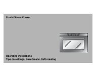
Burner locations<br />
The gas burners<br />
Operation<br />
14<br />
5<br />
3 1 4<br />
2 7<br />
1 Pan supports<br />
2 Control knobs<br />
3 Auxiliary burner (up to 1 kW)<br />
4 Semi-rapid burner (up to 1,75 kW)<br />
5 Rapid burner (up to 3 kW)<br />
6 Double flame burner (up to 3,3 kW)<br />
7 Dual double-flame wok burner (up to 5 kW)<br />
10<br />
4<br />
6<br />
3 1 4<br />
2<br />
3 4<br />
There are indications to show which burner each control<br />
knob operates. Fig. 12.<br />
Fig. 12<br />
It is essential to ensure that all the burner parts and pan<br />
supports are correctly installed for the appliance to work<br />
correctly. Fig.13-14.<br />
Fig. 13<br />
6<br />
Fig. 14
Switching on<br />
automatically<br />
If your cooktop can be switched on automatically (ignition<br />
sparkers):<br />
1. Press the chosen burner control knob and turn it<br />
anticlockwise to the maximum power setting.<br />
While the control knob is still pressed down, sparks are<br />
produced on all burners. The flame ignites (it is no longer<br />
necessary to press down the control knob).<br />
2. Turn the control knob to the required setting.<br />
If it does not come on, turn the control knob to the off<br />
setting and repeat the steps above. This time, press and<br />
hold the control knob for longer (up to 10 seconds).<br />
Warning! If after 15 seconds the flame does not ignite,<br />
switch off the burner and open a nearby window or door.<br />
Wait at least one minute before trying to switch the burner<br />
on.<br />
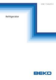
Safety system Depending on the model, your cooktop may have a<br />
Fig. 15<br />
safety system (thermocouple) that prevents the flow of<br />
gas if the burners accidentally switch off. To ensure that<br />
this device is active, switch on the burner as usual and,<br />
without releasing the control knob, press and hold it<br />
down firmly for 4 seconds after lighting the flame. Fig. 15.<br />
Ignition<br />
sparker<br />
Thermocouple<br />
Switching off a burner Turn the corresponding control knob clockwise to the 0<br />
setting.<br />
Power levels The progressive control knobs can be used to control the<br />
power needed, from minimum to maximum power.<br />
Setting $ Control off<br />
Large flame<br />
Economy<br />
flame<br />
— Maximum capacity<br />
˜<br />
or aperture and<br />
electricity on<br />
Minimum capacity<br />
or aperture<br />
For double-flame burners, the inner and outer flames<br />
can be controlled separately.<br />
The available power levels are as follows:<br />
Inner and outer flame on full power.<br />
15
Warnings It is normal to hear a slight whistling noise while the<br />
burner is operating.<br />
When it is first used, it is normal for the burner to give off<br />
odours; this does not pose any risk and does not indicate<br />
a malfunction; they will disappear in time.<br />
A few seconds after switching off the burner, it will make<br />
a sound (thud). This is not a fault - this means that the<br />
safety device is no longer operating.<br />
Keep the burner as clean as possible. If the ignition<br />
sparkers are dirty they will not light properly. Clean them<br />
periodically using a small non-wire brush. Bear in mind<br />
that the ignition sparkers must not suffer any serious<br />
impacts.<br />
An orange-coloured flame is normal. This is caused by<br />
the presence of dust in the atmosphere, spilt liquids, etc.<br />
The kitchen will become hot and humid when this gas<br />
appliance is used. You must therefore ensure that the<br />
kitchen is well ventilated: either keep the natural<br />
ventilation apertures open, or install a ventilation system<br />
(extractor hood).<br />
If using the appliance intensively for prolonged periods,<br />
you may require additional ventilation (e.g. by opening a<br />
window) or more effective ventilation (e.g. by increasing<br />
the cooktop's ventilation, if possible).<br />
If the burner flames are accidentally blown out, switch off<br />
the burner operating control knob and do not try to relight<br />
it for at least one minute.<br />
Use “Large” setting to bring the pan to the boil, then<br />
adjust the flame between “Large flame” and “Economy<br />
flame” to maintain the required pan temperature.<br />
16<br />
Outer flame on minimum, inner flame on full power.<br />
Inner flame on full power.<br />
Inner flame on minimum power.
Suitable pans<br />
Accessories<br />
Additional wok pan<br />
support<br />
Wok pan<br />
Additional coffee maker<br />
support<br />
Important:<br />
The use of a cooktop leads to the production of heat and<br />
moisture in the kitchen. For this reason make sure that<br />
the room is properly ventilated. Keep natural ventilation<br />
openings, such as windows, open or provide a<br />
mechanical ventilation device (e.g. a range hood or<br />
overhead exhaust fan). An orangy flame is normal and<br />
simply indicates the presence of salt in the atmosphere<br />
(from cooking). If the flame has yellow patches, this is not<br />
a fault (of any kind).<br />
The chart below gives the correct pan usage for each burner<br />
Burner Minimum pan<br />
diameter<br />
Maximum pan<br />
diameter<br />
Semi-rapid burner 14 cm 20 cm<br />
Rapid burner 22 cm 26 cm<br />
Wok burner 22 cm<br />
Auxiliary burner 12 cm 16 cm<br />
Depending on the model, the hob may include the<br />
following accessories. These are also available from the<br />
Technical Assistance Service.<br />
Additional wok pan support: to be used exclusively on<br />
double and triple-flame burners with concave-based<br />
pans.<br />
Using these pans may cause some temporary<br />
deformation of the grease splash tray. This is normal and<br />
does not affect the operation of the appliance.<br />
Only for use on the auxiliary burner with pans which are<br />
no more than 12 cm in diameter.<br />
The manufacturer accepts no liability if these accessories<br />
are not used or are used incorrectly.<br />
17
Cooking<br />
recommendation<br />
18<br />
Wok burner Boiling, grilling,<br />
browning and<br />
Asian food (wok).<br />
Rapid burner Steaks, omelettes,<br />
frying.<br />
Semi-rapid burner Steaming potatoes,<br />
fresh vegetables,<br />
stews, pasta.<br />
Auxiliary burner Casseroles, rice<br />
pudding and<br />
caramels.<br />
Very high, high Medium Low<br />
Reheating and keeping things hot:<br />
cooked and pre-cooked dishes.<br />
Rice, white sauce<br />
and ragout.<br />
Steaming and<br />
vegetables.<br />
Reheating, keeping things hot and<br />
making tasty casseroles.<br />
Defrosting and<br />
slow cooking:<br />
vegetables, fruits<br />
and frozen<br />
products.<br />
Melting:<br />
butter, chocolate<br />
and jelly.<br />
Do not place anything, eg. flame tamer,<br />
asbestos mat, between pan and pan support as<br />
serious damage to the appliance may result.<br />
Do not remove the pan support and enclose the<br />
burner with a wok stand as this will concentrate<br />
and deflect heat onto the hotplate.<br />
Do not use large pots or heavy weights which<br />
can bend the pan support or deflect flame onto<br />
the hotplate.
Precautions for use<br />
The following advice is intended to help you save energy<br />
and prevent pan damage:<br />
Use pans which are the right size for each burner.<br />
Do not use small pans on large burners. The flame<br />
should not touch the sides of the pan.<br />
Do not use damaged pans, which do not sit evenly on<br />
the cooktop. Pans may tip over.<br />
Only use pans with a thick, flat base.<br />
Do not cook without using a lid and make sure the lid is<br />
properly fitted to avoid wasting energy.<br />
Always place the pan right over the burner, not to one<br />
side. Otherwise it could tip over.<br />
Do not place large pans on the burners near the control<br />
knobs. These may be damaged by the very high<br />
temperatures.<br />
Place the pans on the pan supports, never directly on<br />
the burner.<br />
Pans should be placed on the cooktop carefully.<br />
Do not strike the cooktop and do not place excessive<br />
weight on it.<br />
Make sure that the pan supports and burner covers are<br />
correctly positioned before using the appliance.<br />
19
Cleaning and<br />
maintenance<br />
Cleaning Once the appliance is cool, use a sponge to clean it with<br />
soap and water.<br />
After each use, clean the surface of the respective burner<br />
parts once they have cooled down. If any residue is left<br />
(baked-on food, drops of grease etc.), however little, it will<br />
become stuck to the surface and more difficult to remove<br />
later. The holes and grooves must be clean for the flame<br />
to ignite properly.<br />
The movement of some pans may leave metal residue on<br />
the pan supports.<br />
Clean the burners and pan supports using soapy water<br />
and scrub with a non-wire brush.<br />
If the pan supports are fitted with rubber rests, ensure that<br />
these are also cleaned. The rests may come loose and<br />
the pan support may scratch the hob.<br />
Always dry the burners and pan supports completely.<br />
Water droplets or damp patches on the hob at the start<br />
of cooking may damage the enamel.<br />
After cleaning and drying the burners, make sure the<br />
burner covers are correctly placed on the diffuser.<br />
Unsuitable products Do not use steam cleaners. This could damage the hob.<br />
If your hob is fitted with a glass or aluminium panel, never<br />
use a knife, scraper or similar to clean the point where it<br />
joins the metal.<br />
Maintenance Always clean off any liquid as soon as it is spilt: you will<br />
save yourself any unnecessary effort.<br />
Do not leave acidic liquids (e.g. lemon juice, vinegar, etc.)<br />
on the hob.<br />
Where possible, do not allow salt to come into contact<br />
with the surface of the electric hob.<br />
The ring cover of the double or triple flame burner and<br />
stainless steel parts such as hotplate rings, top sheet and<br />
the area around the burners may become discoloured<br />
over time. This is normal because of the high<br />
temperatures. Each time the appliance is used these<br />
parts should be cleaned with a product that is suitable for<br />
stainless steel.<br />
The stainless steel cleaner must not be used in the area<br />
around the controls. The (printed) symbols may be wiped<br />
off.<br />
20
Service<br />
DO NOT MODIFY THIS APPLIANCE.<br />
Only authorized personnel from the Service Centre are<br />
qualified to work on the appliance.<br />
Sometimes certain faults detected can be easily resolved.<br />
Before calling the Service Centre, bear in mind the<br />
following advice:<br />
Fault Possible cause Solution<br />
The general electrical<br />
system is malfunctioning.<br />
The automatic on<br />
function does not work.<br />
The burner flame is not<br />
uniform.<br />
The flow of gas does not<br />
appear normal or no gas<br />
comes out.<br />
The kitchen smells of<br />
gas.<br />
The safety valves on one<br />
of the burners are not<br />
working.<br />
Defective fuse.<br />
The automatic safety switch or<br />
circuit breaker has tripped.<br />
There may be food or cleaning<br />
products stuck between the<br />
ignition sparkers and the<br />
burners.<br />
The burners are wet.<br />
The burner covers are not<br />
correctly positioned.<br />
The appliance is not earthed, is<br />
not correctly connected or the<br />
earth wire is faulty.<br />
The burner components are not<br />
correctly positioned.<br />
The grooves on the burner are<br />
dirty.<br />
The gas supply is blocked via<br />
intermediary valves.<br />
If the gas is supplied from a<br />
gas cylinder, check that this is<br />
not empty.<br />
A gas tap has been left on.<br />
There may be a leak in the gas<br />
cylinder coupling.<br />
The control knob was not held<br />
down for long enough.<br />
The grooves on the diffuser are<br />
dirty.<br />
Check the fuse in the main fuse<br />
box and change it if it is damaged.<br />
Check the main control panel to<br />
see if the automatic safety switch<br />
or circuit breaker has tripped.<br />
The space between the ignition<br />
sparker and the burner must be<br />
clean.<br />
Dry the burner covers carefully.<br />
Check that the covers are correctly<br />
positioned.<br />
Contact the electrical installer.<br />
Ensure the components are<br />
correctly positioned.<br />
Clean the grooves on the diffuser.<br />
Open all intermediary valves.<br />
Change the gas cylinder.<br />
Turn off the gas taps.<br />
Check that the coupling is sound.<br />
Once the burner is lit, hold the<br />
control knob down a few seconds<br />
longer. Clean the grooves on the<br />
diffuser.<br />
Any of the following are considered to be abnormal<br />
operation and may require servicing:<br />
Yellow tipping of the cooktop burner flame.<br />
Sooting up of cooking utensils.<br />
Burners not lighting properly.<br />
Gas valves, which are difficult to turn in case the<br />
appliance fails to operate correctly, contact the<br />
authorised service provider in your area.<br />
21
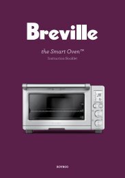
Wiring diagram<br />
A. Switch<br />
B. Blue wire<br />
C. Brown wire<br />
D. Terminal<br />
E. Ignition module<br />
www.bosch-home.com<br />
ROBERT BOSCH HAUSGERÄTE GMBH<br />
CIF: A-28-893550<br />
E-Nr: <strong>PCR915B91A</strong><br />
FD<br />
Gas type<br />
NG ULPG<br />
Gas type<br />
NG ULPG<br />
Test point pressure (kPa)<br />
Injectors marks<br />
LHF<br />
LHR<br />
RHF<br />
RHR<br />
Centre<br />
1,0<br />
155<br />
90<br />
118<br />
118<br />
85/140<br />
2,75<br />
85<br />
50<br />
67<br />
67<br />
46/71<br />
Test point pressure (kPa)<br />
Injectors marks<br />
LHF<br />
LHR<br />
RHF<br />
RHR<br />
CF<br />
CR<br />
1,0<br />
160<br />
90<br />
160<br />
118<br />
90<br />
118<br />
2,75<br />
91<br />
50<br />
91<br />
67<br />
50<br />
67<br />
HGC (MJ)<br />
45,40 43,50<br />
HGC (MJ)<br />
44,20 41,00<br />
In compliance with AS/NZS 3100 and AS 4551:2008 In compliance with AS/NZS 3100 and AS 4551:2008<br />
Preinstalled NG<br />
Preinstalled NG<br />
MADE IN SPAIN<br />
Distributed by BSH Home <strong>Appliances</strong> Pty Ltd GMK 10047<br />
22<br />
www.bosch-home.com<br />
ROBERT BOSCH HAUSGERÄTE GMBH<br />
CIF: A-28-893550<br />
E-Nr: P CT915B91A<br />
FD<br />
MADE IN SPAIN<br />
Distributed by BSH Home <strong>Appliances</strong> Pty Ltd GMK 10047