

10" Band Saw Model 3104 - Manual & Guides
10" Band Saw Model 3104 - Manual & Guides
10" Band Saw Model 3104 - Manual & Guides

Create successful ePaper yourself
Turn your PDF publications into a flip-book with our unique Google optimized e-Paper software.
miter gauge extension allows you to lower the<br />
blade guard within 1/8" of the material to be<br />
cut without any interference from the blade<br />
guard .<br />
RIPPING SLOT . . . Place miter gauge in ripping<br />
slot to desired width and tighten screw . (A rip<br />
scale is provided for a reference .<br />
HOUSING COVER LATCHES . . There are<br />
seven latches to remove the housing cover . To<br />
release latches, place your index finger at one<br />
end of the latch and gently lift the other end<br />
with your thumb. To lock the latch, press down<br />
until the open end of the latch snaps securely<br />
over the locking tab . Always make sure the<br />
latches are securely snapped before turning on<br />
the saw .<br />
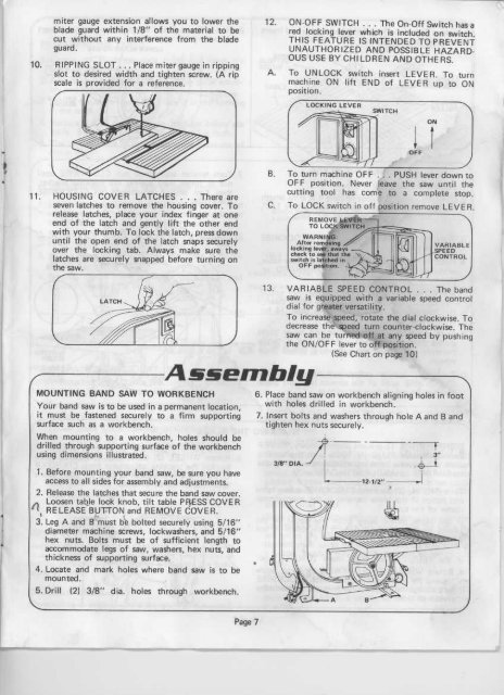
MOUNTING BAND SAW TO WORKBENCH<br />
Assembly<br />
Your band saw is to be used in a permanent location,<br />
it must be fastened securely to a firm supporting<br />
surface such as a workbench .<br />
When mounting to a workbench, holes should be<br />
drilled through supporting surface of the workbench<br />
using dimensions illustrated .<br />
1 . Before mounting your band saw, be sure you have<br />
access to all sides for assembly and adjustments .<br />
2 . Release the latches that secure the band saw cover .<br />
Loosen table lock knob, tilt table PRESS COVER<br />
t RELEASE BUTTON and REMOVE COVER .<br />
3 . Leg A and B 'must be bolted securely using 5/16"<br />
diameter machine screws, lockwashers, and 5/16"<br />
hex nuts . Bolts must be of sufficient length to<br />
accommodate legs of saw, washers, hex nuts, and<br />
thickness of supporting surface .<br />
4 . Locate and mark holes where band saw is<br />
mounted .<br />
to be<br />
5 . Drill (2) 3/8" dia . holes through workbench .<br />
Page 7<br />
12 . ON-OFF SWITCH . . . The On-Off Switch has a<br />
red locking lever which is included on switch .<br />
THIS FEATURE IS INTENDED TO PREVENT<br />
UNAUTHORIZED AND POSSIBLE HAZARD-<br />
OUS USE BY CHILDREN AND OTHERS .<br />
A . To UNLOCK switch insert LEVER . To turn<br />
machine ON lift END of LEVER up to ON<br />
position .<br />
LOCKING LEVER<br />
SWITCH<br />
B . To turn machine OFF . . . PUSH lever down to<br />
OFF position . Never leave the saw until the<br />
cutting tool has come to a complete stop .<br />
C . To LOCK switch in off position remove LEVER .<br />
3/B" DIA.<br />
REMOVE LEVER<br />
TO LOCK SWITCH<br />
WARNING :<br />
After removing<br />
locking lever awavs<br />
check to see that the N<br />
switch a latched in<br />
OFF position .<br />
13 . VARIABLE SPEED CONTROL . . . The band<br />
saw is equipped with a variable speed control<br />
dial for greater versatility .<br />
To increase speed, rotate the dial clockwise . To<br />
decrease the speed turn counter-clockwise . The<br />
saw can be turned off at any speed by pushing<br />
the ONiOF F lever to off position .<br />
(See Chart on page 10)<br />
6 . Place band saw on workbench aligning holes in foot<br />
with holes drilled in workbench .<br />
7 . Insert bolts and washers through hole A and B and<br />
tighten hex nuts securely .<br />
ON<br />
VARIABLE<br />
SPEED<br />
CONTROL<br />
OAF