Slip Ring Assemblies Program 5100 - Conductix-Wampfler
Slip Ring Assemblies Program 5100 - Conductix-Wampfler
Slip Ring Assemblies Program 5100 - Conductix-Wampfler

Create successful ePaper yourself
Turn your PDF publications into a flip-book with our unique Google optimized e-Paper software.
<strong>Slip</strong> <strong>Ring</strong> Assembly<br />
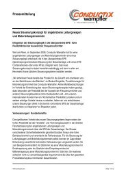
Built-in <strong>Slip</strong> <strong>Ring</strong> Assembly ES45/1 25 A /400 V (415 V) 1)<br />
Electrical data<br />
• Voltage:<br />
- max. 400 V~= (415 V) 1)<br />
- according to DIN VDE 0110<br />
- overtension category III<br />
- insulating material group II<br />
- degree of contamination 3<br />
• Current: mA to 25 A, at max. 30°C<br />
and 100% duty cycle<br />
• <strong>Slip</strong> rings:<br />
- ø 45 x 8 mm, brass (MS)<br />
- distance between rings 14 mm<br />
• Brush holder assembly:<br />
- brush holders with 2 pressed-on<br />
brushes (Cu) 20 x 8 mm<br />
- Connecting fl at plug 6.3<br />
(DIN 46244) for fl at socket 6.3<br />
(DIN 46247)<br />
• Protection class: IP 00<br />
~ 39<br />
a<br />
8<br />
24<br />
68<br />
ø 70<br />
di ø 22<br />
da ø 25h9<br />
ø d1<br />
ø 45<br />
a = (number of poles-1) x 14<br />
ø 45<br />
38.5<br />
R70<br />
6.3<br />
12 poles with terminal posts<br />
36<br />
ø 83<br />
18<br />
13 - 18 poles with insulated terminals<br />
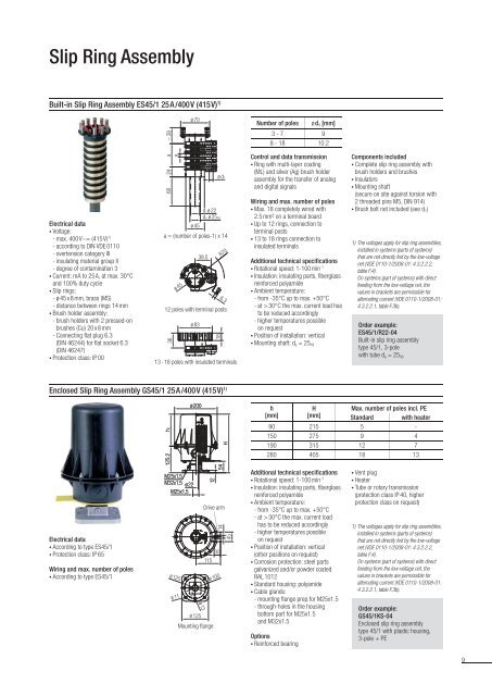
Enclosed <strong>Slip</strong> <strong>Ring</strong> Assembly GS45/1 25 A /400 V (415 V) 1)<br />
Electrical data<br />
• According to type ES45/1<br />
• Protection class: IP 65<br />
Wiring and max. number of poles<br />
• According to type ES45/1<br />
125,2 125.2 hh2<br />
M25x1,5 M25x1.5<br />
M32x1,5 M32x1.5 ø 22<br />
M25x1,5 M25x1.5<br />
ø 125<br />
ø 11<br />
ø 200<br />
ø 13<br />
ø 125<br />
12<br />
54<br />
30<br />
115<br />
Mounting fl ange<br />
H<br />
Drive arm<br />
14<br />
ø 100<br />
45<br />
Number of poles ø d1 [mm]<br />
3 - 7 9<br />
8 - 18 10.2<br />
Control and data transmission<br />
• <strong>Ring</strong> with multi-layer coating<br />
(ML) and silver (Ag) brush holder<br />
assembly for the transfer of analog<br />
and digital signals<br />
Wiring and max. number of poles<br />
• Max. 18 completely wired with<br />
2.5 mm² on a terminal board<br />
• Up to 12 rings, connection to<br />
terminal posts<br />
• 13 to 18 rings connection to<br />
insulated terminals<br />
Additional technical specifi cations<br />
• Rotational speed: 1-100 min-1 • Insulation: insulating parts, fi berglass<br />
reinforced polyamide<br />
• Ambient temperature:<br />
- from -35°C up to max. +50°C<br />
- at > 30°C the max. current load has<br />
to be reduced accordingly<br />
- higher temperatures possible<br />
on request<br />
• Position of installation: vertical<br />
• Mounting shaft: da = 25h9<br />
h<br />
[mm]<br />
H<br />
[mm]<br />
Components included<br />
• Complete slip ring assembly with<br />
brush holders and brushes<br />
• Insulators<br />
• Mounting shaft<br />
(secure on site against torsion with<br />
2 threaded pins M5, DIN 914)<br />
• Brush bolt not included (see d 1)<br />
1) The voltages apply for slip ring assemblies,<br />
installed in systems (parts of systems)<br />
that are not directly fed by the low-voltage<br />
net (VDE 0110-1/2008-01: 4.3.2.2.2,<br />
table F.4).<br />
On systems (part of systems) with direct<br />
feeding from the low-voltage net, the<br />
values in brackets are permissible for<br />
alternating current (VDE 0110-1/2008-01:<br />
4.3.2.2.1, table F.3b).<br />
Order example:<br />
ES45/1/R22-04<br />
Built-in slip ring assembly<br />
type 45/1, 3-pole<br />
with tube da = 25h9<br />
Max. number of poles incl. PE<br />
Standard with heater<br />
90 215 5 -<br />
150 275 9 4<br />
190 315 12 7<br />
280 405 18 13<br />
Additional technical specifi cations<br />
• Rotational speed: 1-100 min-1 • Insulation: insulating parts, fi berglass<br />
reinforced polyamide<br />
• Ambient temperature:<br />
- from -35°C up to max. +50°C<br />
- at > 30°C the max. current load<br />
has to be reduced accordingly<br />
- higher temperatures possible<br />
on request<br />
• Position of installation: vertical<br />
(other positions on request)<br />
• Corrosion protection: steel parts<br />
galvanized and/or powder coated<br />
RAL 1012<br />
• Standard housing: polyamide<br />
• Cable glands:<br />
- mounting fl ange prep.for M25x1.5<br />
- through-holes in the housing<br />
bottom part for M25x1.5<br />
and M32x1.5<br />
Options<br />
• Reinforced bearing<br />
• Vent plug<br />
• Heater<br />
• Tube or rotary transmission<br />
(protection class IP 40, higher<br />
protection class on request)<br />
1) The voltages apply for slip ring assemblies,<br />
installed in systems (parts of systems)<br />
that are not directly fed by the low-voltage<br />
net (VDE 0110-1/2008-01: 4.3.2.2.2,<br />
table F.4).<br />
On systems (part of systems) with direct<br />
feeding from the low-voltage net, the<br />
values in brackets are permissible for<br />
alternating current (VDE 0110-1/2008-01:<br />
4.3.2.2.1, table F.3b).<br />
Order example:<br />
GS45/1KS-04<br />
Enclosed slip ring assembly<br />
type 45/1 with plastic housing,<br />
3-pole + PE<br />
9