
You also want an ePaper? Increase the reach of your titles
YUMPU automatically turns print PDFs into web optimized ePapers that Google loves.
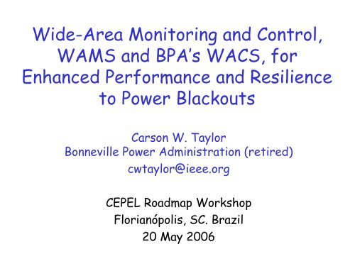
Wide-Area Monitoring and Control,<br />
<strong>WAMS</strong> and BPA’s <strong>WACS</strong>, for<br />
Enhanced Performance and Resilience<br />
to Power Blackouts<br />
Carson W. Taylor<br />
Bonneville Power Administration (retired)<br />
cwtaylor@ieee.org<br />
CEPEL Roadmap Workshop<br />
Florianópolis, SC. Brazil<br />
20 May 2006
What is <strong>WAMS</strong>?<br />
■ <strong>WAMS</strong> is monitoring of power system dynamic<br />
performance:<br />
• Mainly electromechanical and voltage dynamics<br />
• RMS values or phasors, typical sampling at 20–60 Hz<br />
• Fault recorders, oscillographs, power quality instruments<br />
typically not part of <strong>WAMS</strong><br />
• Oriented towards centralized or networked monitoring<br />
• Oriented towards continuous recording with archiving of<br />
interesting events<br />
• Term “<strong>WAMS</strong>” originated at BPA in late 1980s<br />
• “<strong>WAMS</strong>” includes test and analysis techniques such as<br />
the Fourier and Prony methods for system identification?<br />
2
Better Information Supports Better Decisions<br />
Disturbances<br />
System planning<br />
System operation<br />
Automatic control<br />
Source: John Hauer<br />
Decision<br />
Processes<br />
Power<br />
System<br />
Information<br />
Unobserved response<br />
Observed response<br />
Measurement<br />
Based<br />
Information<br />
System<br />
3
<strong>WAMS</strong> is More than Data<br />
Wisdom<br />
Knowledge<br />
Information<br />
Data<br />
Operator needs<br />
information, not data.<br />
4
Source: John Hauer<br />
WECC Phasor Network in<br />
2005 (<strong>WAMS</strong>)<br />
60 Phasor Measurement Units<br />
(PMUs)<br />
382 voltage or current phasors,<br />
plus bus frequencies<br />
8 Phasor Data Concentrators<br />
(PDCs) at control centers<br />
BCH<br />
BPA<br />
CAISO<br />
PG&E<br />
SCE<br />
APS/SRP<br />
PNM<br />
WAPA<br />
4 inter company data links<br />
5
BPA Phasor Measurement System<br />
V - I - F<br />
Measurement<br />
- substations<br />
PMU<br />
PMU<br />
PMU<br />
Direct<br />
exchange with<br />
other utilities<br />
Source: Ken Martin<br />
Data input &<br />
management<br />
- control center<br />
Phasor Data<br />
Concentrator<br />
(PDC)<br />
Correlates data,<br />
feeds selected<br />
applications,<br />
monitors system<br />
PDC<br />
Operations<br />
monitors – display<br />
& alarms<br />
SCADA - Voltage,<br />
angle & frequency<br />
Other displays -<br />
Power World, etc.<br />
StreamReader<br />
Display & recording<br />
Data storage<br />
System<br />
controls<br />
Real-time<br />
controls:<br />
Voltage &<br />
reactive<br />
stability;<br />
interarea<br />
angle limits<br />
6
BPA StreamReader, Loss of Colstrip, 6 Sept. 01<br />
LabVIEW software, real-time display on PC. StreamReader computes<br />
active and reactive power from phasors, etc.<br />
7
BPA StreamReader: Time and Frequency Domain<br />
Ambient activity, 7 June 2000. Source: John Hauer, PNNL<br />
8
Eastern Interconnection Phasor Project<br />
■ August 14, 2003 blackout reports had strong<br />
recommendations for synchronized measurements<br />
■ EIPP organization (http://phasors.pnl.gov):<br />
• AEP, TVA, Entergy, Ameren, NYPA, DoE, NERC, PNNL, etc.<br />
■ Four state estimator integration projects<br />
• State measurements<br />
• Texas A&M finding – Accuracy of state estimation<br />
drastically improves by strategically placing PMUs at 10% of<br />
the network buses<br />
■ On-line efforts:<br />
• Angular separation analysis and alarming<br />
• Interarea oscillations<br />
• Real-time stability applications<br />
Source: Bob Cummings, NERC<br />
9
EIPP Progress, 2005<br />
■ 57 PMUs in Eastern Interconnection<br />
• 24 more in next 12 months<br />
• Over 400 digital relays – extending capability<br />
■ 5 Phasor Data Concentrators<br />
• Entergy, TVA, AEP, NYISO, Ameren<br />
• Internet VPNs for communications<br />
■ TVA Super PDC Operational<br />
• Other PDCs connected<br />
• 24 PMUs connected<br />
■ On-Line Applications in testing<br />
Source: Bob Cummings, NERC<br />
10
Summary: Wide-Area Measurements [6]<br />
■ Purpose: avoid system problems, not just record them.<br />
■ Value: information has the same value as decisions<br />
based upon it. Insurance against operational<br />
uncertainties.<br />
■ Applications: should support tests and analysis, and<br />
real-time system operations<br />
■ Event detection logic: trigger snapshot recordings or<br />
apply to archived records.<br />
• Continuous recording preferred; difficult to detect distant<br />
events<br />
■ Costs: Hardware is cheap, engineering time expensive<br />
11
Power System Stability Controls<br />
Local and Wide-Area<br />
Power System<br />
Disturbances<br />
switch capacitor/reactor banks<br />
direct<br />
detection<br />
(SPS) trip generators/loads<br />
Discontinuous<br />
Controls<br />
response detection<br />
(<strong>WACS</strong>)<br />
Power<br />
System<br />
Dynamics<br />
Continuous<br />
Feedback<br />
Controls<br />
(generators)<br />
12<br />
∆ y
Event-Based Wide-Area Stability Controls<br />
■ Special Protection System (SPS)/Remedial Action<br />
Scheme (RAS)/Emergency Control<br />
■ Many schemes in service, fast and reliable<br />
■ Direct detection of pre-selected outages:<br />
• Feedforward control<br />
• Signal to central logic, then signal to power plant or<br />
substation for action<br />
• Generator/load tripping, reactive power compensation<br />
switching<br />
■ Complex, 24/7 RAS dispatcher<br />
■ Expensive (high redundancy, hardware for each<br />
potential outage). Recent cost of $575K for lineloss<br />
logic at both ends of line with transfer trip to<br />
two control centers.<br />
13
Response-Based Wide-Area Stability Controls<br />
■ Detect any disturbance by measured response<br />
(feedback)<br />
■ Improved observability and controllability<br />
compared to local control<br />
• Example: load shedding based on several voltages and<br />
generator reactive power outputs rather than local<br />
voltage<br />
■ Continuous versus discontinuous controls<br />
■ Continuous:<br />
• “Wide-area PSS”<br />
• Remote signals for control of HVDC, SVC, TCSC<br />
14
Response-Based Wide-Area Stability Controls<br />
■ Facilitated by IT:<br />
• Digital sensors, communications, controllers<br />
• Fiber optic communications<br />
■ Time delays/latencies pose challenges:<br />
• But control feasible for interarea oscillations<br />
■ Example—low frequency mode with 3 second<br />
period:<br />
• Need first swing stabilization<br />
• Impulse (short circuit) response peak at 0.75 second<br />
• Step (line/generator outage) response peak at 1.5 second<br />
15
Discontinuous Wide-Area Stability Controls<br />
■ Response-based to stabilize large disturbances:<br />
• First swing stabilization<br />
• Reduce stress for improved damping<br />
• Region of attraction/post-disturbance equilibrium<br />
■ Generator/load tripping, capacitor/reactor bank<br />
switching—powerful control actions:<br />
• BPA has 550-kV capacitor banks up to 460 MVAr<br />
■ Single switching action, or<br />
■ True feedback—observe response, take action,<br />
observe effect, take further action if necessary<br />
■ SAFER than continuous control<br />
• Biological system analogy—stimuli must be above<br />
activation threshold<br />
16
BPA Wide-Area Control System (<strong>WACS</strong>)<br />
■ On-line demonstration uses existing wide-area<br />
measurement systems (<strong>WAMS</strong>)<br />
• Synchronized phasor measurement units (PMUs)<br />
• Fiber optic communications<br />
• 30 packets per second data rate (60 per second future?)<br />
■ Existing Remedial Action Scheme (RAS) transfer trip<br />
from control center to power plants and substations<br />
available:<br />
• Generator tripping and capacitor/reactor bank switching<br />
■ Control computer(s) at control center(s):<br />
• LabVIEW RT hardware and software (www.ni.com)<br />
• Currently on-line at control center with real-time phasor<br />
measurement inputs (monitor mode)<br />
17
Latest Generation PMU<br />
•Based on digital protective relay hardware and software<br />
•60 packets/second data rate, adjustable data rate and filtering<br />
•Used for new BPA installations — several vendors<br />
18
Flexible Platform for Control<br />
GPS<br />
voltage phasors<br />
current phasors<br />
frequencies<br />
fiber optics<br />
SCADA<br />
control center LAN<br />
control<br />
computers<br />
BPA<br />
control<br />
center(s)<br />
power<br />
system<br />
generator/load<br />
tripping<br />
reactive power<br />
switching<br />
Other actions
<strong>WACS</strong> — Flexible Platform for Control<br />
20
Fiber Optic Latency<br />
Delay in packets from Slatt PMU to control center PDC over one minute period.<br />
PDC processing adds 5–6 ms.<br />
21
<strong>WACS</strong> Computers, NI LabVIEW RT<br />
RT Engine (Networked to<br />
the Power System Phasor<br />
Measurement Units)<br />
Connection Interface to the<br />
Transfer Trip<br />
Communications Network<br />
Host PC (Networked to the<br />
RT Engine)<br />
22
<strong>WACS</strong> Laboratory Installation<br />
23
Source: John Hauer<br />
<strong>WACS</strong> Inputs<br />
12 PMU voltage magnitude<br />
measurements from:<br />
Malin<br />
Captain Jack (2 busses)<br />
Summer Lake (2 busses)<br />
Slatt (2 busses)<br />
Ashe (2 busses)<br />
John Day<br />
McNary 500 (2 busses)<br />
PMU-derived generator reactive<br />
power measurements from:<br />
John Day (4 generator lines)<br />
Big Eddy (4 generator lines)<br />
McNary (5 generator lines)<br />
Ashe (Columbia Gen. Station)<br />
Slatt (Boardman plant)<br />
Calpine Hermiston<br />
BPA fiber optic communications<br />
(SONET)
Why Not Use Voltage Phase Angles?<br />
■ Under study for future [1, Appendix III]<br />
■ Reliable, high speed signals not available from<br />
other utilities<br />
■ Voltage phase angle susceptible to GPS glitches<br />
■ Voltage magnitudes near swing center closely<br />
related to angle difference swings<br />
■ Voltage phase angles state variable for steadystate<br />
analysis (power flow program) but not for<br />
dynamics<br />
25
for high BC exports<br />
26
Two Algorithms<br />
AC Intertie<br />
Pacific NW<br />
to California<br />
First swing (spring)<br />
Vmag or VmagQ algorithm<br />
Simultaneous<br />
Transfer<br />
Nomogram<br />
North to South flow in Washington state<br />
High flow means generation farther away<br />
Ensure RoA and<br />
post disturbance<br />
secure operation<br />
VmagQ algorithm<br />
Damping (summer)<br />
Vmag or VmagQ<br />
algorithm<br />
27
Voltage Magnitude (Vmag) Algorithm<br />
■ Control accumulates volt-seconds of weighted<br />
average voltage from twelve 500-kV measurements:<br />
• Like inverse-time undervoltage relay<br />
• Accumulation (integration) starts when weighted voltage<br />
decays below threshold. No accumulation if present input is<br />
higher than previous<br />
• Control action when accumulation reaches setpoint and<br />
weighted voltage level is below a setpoint<br />
• Accumulator resets if weighted voltage recovers<br />
• Time frame of around one second<br />
■ Separate accumulators for generator tripping and<br />
500-kV reactive power compensation switching<br />
28
Vmag Algorithm Block Diagram for Simulation<br />
Voltage magnitude inputs, weights,<br />
and number of bus measurements<br />
Malin 1.0 01<br />
Captain Jack 1.0 02<br />
Summer Lake 1.0 02<br />
Slatt 0.5 02<br />
John Day 0.5 01<br />
McNary 500 0.2 02<br />
Ashe 0.2 02<br />
Sum 7.3 12<br />
V<br />
W<br />
Arrays (vectors) of 12 voltages<br />
and weights. Valid voltage<br />
ranges are 360–650 kV.<br />
∑ × Vi<br />
Wi<br />
W<br />
∑<br />
V Threshold<br />
520 kV for gen. trip,<br />
525 kV for cap./reactor switching<br />
i<br />
V Avg<br />
Notes:<br />
1. Individual computations and settings for each controlled device.<br />
Currently we use identical settings for all generator tripping locations,<br />
and different identical settings for all capacitor/reactor switching<br />
locations. Identical voltage magnitude weights are used for all devices.<br />
2. Current settings are shown. Latest settings are on ini file.<br />
3. Accumulation is blocked if present VAvg greater than VAvg of last<br />
execution cycle. Reset when VAvg recovers above VThreshold .<br />
-<br />
+<br />
0<br />
HV<br />
Gate<br />
Accumulator<br />
Setpoint<br />
4 kV-seconds for gen. trip<br />
2 kV-seconds for cap./reactor switching<br />
Σ( .<br />
)∆t<br />
Accumulator<br />
Note 3<br />
V supervise<br />
0<br />
<<br />
1<br />
&<br />
490 kV for gen. trip<br />
520 kV for cap./reactor switching<br />
Control<br />
Output<br />
29
Simulation Example: Transient Stability<br />
■ Outage of nuclear units in south:<br />
• Two Palo Verde units, 2700 MW<br />
• Inertia and governor action in north loads North–South<br />
intertie<br />
■ Use <strong>WACS</strong> to extend Pacific intertie transfer<br />
capability:<br />
• Example show gain of 300 MW (4700 MW to 5000 MW)<br />
30
for high BC exports<br />
31
Existing controls, 4700 MW intertie loading<br />
Malin<br />
500-kV voltages<br />
575 kV<br />
550 kV<br />
525 kV<br />
500 kV<br />
475 kV<br />
450 kV<br />
425 kV<br />
Two Palo Verde outage at one second (2710 MW), Reactive power switching<br />
at Malin, Fort Rock at 2.33–2.8 s.<br />
32
w/<strong>WACS</strong>, 5000 MW intertie loading<br />
Malin<br />
500-kV voltages<br />
575 kV<br />
550 kV<br />
525 kV<br />
500 kV<br />
475 kV<br />
450 kV<br />
425 kV<br />
Two Palo Verde outage at one second (2710 MW), generator dropping at<br />
Shrum and Mica (916 MW) at 2.4 s, reactive power switching a Malin, Marion,<br />
Fort Rock at 2.2–2.6 s (FACRI and <strong>WACS</strong>). Base case for sensitivities.<br />
33
Voltage/Reactive Power (VmagQ) Algorithm<br />
■ Generator reactive power outputs are sensitive<br />
indicators of voltage problems<br />
■ Combine using fuzzy logic:<br />
• Weighted voltage magnitude measurements<br />
• Weighted generator reactive power measurements<br />
• Output accumulators similar to Vmag algorithm<br />
■ Reactive power capability is function of active power:<br />
• P, Q measurements from PMUs located at transmission side<br />
• Normalization based on max, min limits<br />
■ Time frame of second (first swing) to tens of seconds:<br />
• Longer-term dynamics: OELs, LTCs, etc.<br />
• Capacitor/reactor bank switching first, followed by generator<br />
tripping as necessary<br />
34
VmagQ Algorithm<br />
V i<br />
Station<br />
measurements<br />
Q gj<br />
Input<br />
processing<br />
u m Defuzzification<br />
(Center of<br />
Gravity)<br />
Normalization<br />
and<br />
weighted<br />
values<br />
u m *<br />
V m<br />
Q gm<br />
Accumulators<br />
and<br />
threshold<br />
logic<br />
Fuzzy<br />
logic<br />
control<br />
To<br />
compensation<br />
stations<br />
and<br />
power plants
Fuzzy Set for Weighted Voltage<br />
36
Fuzzy Set for Weighted Reactive Power<br />
37
Output Fuzzy Set<br />
38
VmagQ Algorithm Fuzzy Logic Rules<br />
Q Avg<br />
PLq<br />
PMq<br />
OKq<br />
NMq<br />
NLq<br />
PLo<br />
1.0<br />
PLo<br />
0.8<br />
PMo<br />
1.0<br />
PMo<br />
0.8<br />
PSo<br />
1.0<br />
5<br />
4<br />
3<br />
2<br />
1<br />
PLo<br />
0.8<br />
PMo<br />
0.8<br />
PSo<br />
1.0<br />
PSo<br />
0.8<br />
ZEo<br />
1.0<br />
10 15<br />
9<br />
8<br />
7<br />
6<br />
PMo<br />
0.5<br />
PSo<br />
0.5<br />
ZEo<br />
1.0<br />
ZEo<br />
1.0<br />
ZEo<br />
1.0<br />
ZEo<br />
1.0<br />
ZEo<br />
1.0<br />
ZEo<br />
1.0<br />
ZEo<br />
1.0<br />
11 16<br />
ZEo<br />
1.0<br />
ZEo<br />
1.0<br />
ZEo<br />
1.0<br />
ZEo<br />
1.0<br />
ZEo<br />
1.0<br />
21<br />
ZEo<br />
1.0<br />
VLOv LOv OKv HIv VHIv<br />
14<br />
13<br />
12<br />
20 25<br />
19<br />
18<br />
17<br />
24<br />
23<br />
22<br />
V Avg<br />
Lower case v, q, o indicate voltage,<br />
reactive power, and output<br />
VLO - Very Low<br />
LO – Low<br />
HI – High<br />
VHI – Very High<br />
NL – Negative Large<br />
NM – Negative Medium<br />
NS – Negative Small<br />
ZE – Zero<br />
PS – Positive Small<br />
PM – Positive Medium<br />
PL – Positive Large<br />
There is no control for high voltage so<br />
inactive rules are set to ZE.<br />
The large number in each cell is the<br />
Degree of Support or weight of the<br />
rule (range is 0 to 1). The small<br />
number is the rule number.<br />
39
Rulebase Editor<br />
40
I/O Characteristic, Weighted Q = 0.5 pu<br />
41
<strong>WACS</strong> Status<br />
■ R&D largely complete with proof of concept, code<br />
verification, and tuning<br />
■ Three years on-line laboratory and control center<br />
monitoring<br />
■ Playback of simulation and archived PDC data<br />
■ BPA deciding on full deployment (~$1.5M):<br />
• Business case in preparation<br />
• Design for WECC certification, new PMUs, SONET<br />
communication expansion, controllers at both control<br />
centers, O&M training, spare parts<br />
42
<strong>WACS</strong> for Voltage Stability<br />
■ Presently <strong>WACS</strong> oriented toward angle stability<br />
for export conditions; BUT…<br />
■ Flexible platform with two existing algorithms<br />
that could be used for load shedding:<br />
• Voltage magnitude based similar to inverse-time relays<br />
• Combination of voltage and generator reactive power<br />
(applicable to August 14, 2003 blackout)<br />
■ <strong>WACS</strong> could be used for other voltage collapse<br />
countermeasures:<br />
• Capacitor/reactor bank switching<br />
• Tap changer blocking, runback, or reverse control<br />
• Boost of high side voltage schedule<br />
43
<strong>WACS</strong> Business Case: Potential Benefits<br />
1. Increased reliability:<br />
• Control for disturbances anywhere in interconnection<br />
• Additional layer of defense: Defense in Depth<br />
• As feedback control, compensate for simulation and<br />
operational uncertainties<br />
• Blackouts happen and cost billions<br />
2. Increased transfer capability, ~300 MW in one<br />
example<br />
3. Flexible, open system platform for rapid control<br />
and monitoring applications<br />
• Future potential with IT advances<br />
• Use of voltage phase angles throughout interconnection<br />
4. Future partial replacement for costly event-<br />
driven RAS<br />
44
Reference<br />
1. C. W. Taylor, D. C. Erickson, K. E. Martin, R. E. Wilson, and V.<br />
Venkatasubramanian, “<strong>WACS</strong>—Wide-Area Stability and Voltage<br />
Control System: R&D and On-Line Demonstration,” Proceedings of<br />
the IEEE special issue on Energy Infrastructure Defense<br />
Systems, Vol. 93, No. 5, pp. 892–906, May 2005.<br />
45
Questions?<br />
46