Carbon CeramiCs For Current transFer - Wind Systems Magazine
Carbon CeramiCs For Current transFer - Wind Systems Magazine
Carbon CeramiCs For Current transFer - Wind Systems Magazine

Create successful ePaper yourself
Turn your PDF publications into a flip-book with our unique Google optimized e-Paper software.
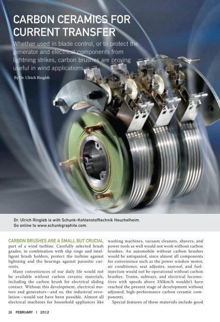
<strong>Carbon</strong> <strong>CeramiCs</strong> <strong>For</strong><br />
<strong>Current</strong> <strong>transFer</strong><br />
Whether used in blade control, or to protect the<br />
generator and electrical components from<br />
lightning strikes, carbon brushes are proving<br />
useful in wind applications.<br />
By Dr. Ulrich Ringleb<br />
Dr. ulrich ringleb is with schunk-Kohlenstofftechnik heuchelheim.<br />
Go online to www.schunkgraphite.com.<br />
<strong>Carbon</strong> brushes are a small but CruCial<br />
part of a wind turbine. Carefully selected brush<br />
grades, in combination with slip rings and intelligent<br />
brush holders, protect the turbine against<br />
lightning and the bearings against parasitic currents.<br />
Many conveniences of our daily life would not<br />
be available without carbon ceramic materials,<br />
including the carbon brush for electrical sliding<br />
contact. Without this development, electrical motors<br />
and generators—and so, the industrial revolution—would<br />
not have been possible. Almost all<br />
electrical machines for household appliances like<br />
28 FEBRUARY | 2012<br />
washing machines, vacuum cleaners, shavers, and<br />
power tools as well would not work without carbon<br />
brushes. An automobile without carbon brushes<br />
would be antiquated, since almost all components<br />
for convenience such as the power window motor,<br />
air conditioner, seat adjuster, sunroof, and fuelinjection<br />
would not be operational without carbon<br />
brushes. Trams, subways, and electrical locomotives<br />
with speeds above 350km/h wouldn’t have<br />
reached the present stage of development without<br />
adjusted, high-performance carbon ceramic components.<br />
Special features of these materials include good
thermal and electrical conductivity and a low friction<br />
coefficient. <strong>Carbon</strong> doesn’t have a liquid phase,<br />
but sublimes at 3500°C, so that there is no welding<br />
with metals. That feature makes carbon superior to<br />
other materials as a material for electrical sliding<br />
contact. <strong>Carbon</strong> ceramics are basically mixtures of<br />
defined carbon containing raw materials with organic<br />
binders. By means of different forming procedures,<br />
components of almost every shape and<br />
size can be fabricated (fig. 1).<br />
At a subsequent temperature treatment up to<br />
3000°C, the green bodies get their characteristic<br />
properties. With a temperature treatment up to<br />
Fig. 1: molecular structure of graphite.<br />
1000°C the materials are called carbon-graphite,<br />
and at a final temperature of 3000°C the result is<br />
electro-graphite. Besides graphitic components,<br />
metal-graphite contains metals such as copper or<br />
silver. Additional treatments involving impregnations<br />
with resins or metals allow further modifications<br />
of the physical properties.<br />
The materials can be adjusted to all possible field<br />
conditions by means of using different raw materials,<br />
their conditioning, and by different shapes.<br />
The good thermal properties are useful in semiconductor<br />
manufacturing and for continuous casting.<br />
Burner nozzles for rockets or brake linings for<br />
automobiles and aircraft are future-oriented developments.<br />
<strong>Carbon</strong> components prove themselves<br />
as replacement for asbestos in the glass industry.<br />
The special tribological properties also show their<br />
advantages in sleeve bearings in pumps. <strong>Carbon</strong>reinforced<br />
fiber materials rank among those with<br />
great future potential due to its high stiffness and<br />
thermal characteristics, and using such grades in<br />
medical applications is just beginning.<br />
appliCations <strong>For</strong> <strong>Carbon</strong> brushes<br />
In the following passage numerous applications for<br />
carbon brushes on wind turbines are described,<br />
along with potential problems and approaches to<br />
solutions (figs. 2, 3).<br />
Generator brushes<br />
The majority of wind turbines are fitted with doubly<br />
fed induction generators (DFIG). The main application<br />
for carbon brushes on wind turbines is<br />
the current transfer on the slip ring of these generators<br />
(fig. 4).<br />
From the extreme cold of Inner Mongolia or<br />
North Dakota to the heat in desert areas, wind<br />
turbines are exposed to harsh environments. Additionally,<br />
there are other challenges like changes in<br />
wind speed, low humidity, and on/off cycles of the<br />
generators, etc. Actually, the carbon brush is only a<br />
windsystemsmag.com 2 9
Fig. 2: typical wind turbine locations where brushes are used.<br />
Fig. 3: power brushes.<br />
Fig. 4: DFiG generator.<br />
30 FEBRUARY | 2012<br />
small part of a wind turbine, but<br />
a very crucial component for efficiency,<br />
maintenance periods,<br />
and output.<br />
From the standpoint of carbon<br />
brushes, there are three<br />
core components for the current<br />
transmission: the carbon brush<br />
itself, the slip ring, and the brush<br />
holder with a spring system. Actual<br />
carbon brush grades consist<br />
mainly of graphite and metal<br />
powder, usually copper, and with<br />
a metal content of 40-60 percent.<br />
<strong>For</strong> difficult cooling conditions,<br />
even brush grades with a high silver<br />
content are in use. Additives<br />
and after-treatments allow adaptation<br />
to these conditions, especially<br />
low humidity. The grade<br />
selection and number of brushes<br />
depend on the rotor current, the<br />
cooling and ambient conditions,<br />
and the slip ring material as well.<br />
During the past 10 years the industry<br />
has gone to great lengths<br />
to improve the brush performance<br />
and shorten maintenance<br />
intervals. Meanwhile, even the<br />
harshest environment is no problem<br />
for carbon brushes. The slip<br />
ring material (fig. 5) is stainless<br />
steel (e.g. X20Cr13 ) or bronze<br />
(e.g. GBz10).<br />
Although the surface speed<br />
is in the normal range for carbon<br />
brushes, the rings are heli-
cally grooved to guarantee<br />
safe contact and to improve<br />
the cooling of the slip ring<br />
surface. During operation a<br />
protective film is formed on<br />
the slip ring surface, called a<br />
patina. This thin film is crucial<br />
for the current transfer<br />
and the friction behavior of<br />
the carbon brushes. The patina<br />
consists of oxides of the<br />
ring material, humidity, and<br />
graphite from the carbon<br />
brush. Any interference of<br />
the film formation process<br />
has a negative influence on<br />
brush performance. That, for<br />
instance, is ambient temperature,<br />
surface temperature of<br />
the ring, current, humidity,<br />
presence of oil or dust, and<br />
state of the ring surface, etc.<br />
An initially sufficient surface<br />
roughness (5-8µm R z , 0,8-1.2<br />
µm R a ) supports the film formation.<br />
Slip rings are available in<br />
different designs: assembled,<br />
or molded. The diameter and<br />
size is a function of the rotor<br />
current. Variants up to 1500<br />
amperes exist. Intelligent<br />
brush holder systems support<br />
the brushes in their function.<br />
Massive and stable, cast<br />
brush holders are the current<br />
state of the art. Referring to<br />
them as “intelligent” means<br />
that the holders have a brush<br />
wear monitoring device included.<br />
Holder systems with<br />
helical tension springs allow<br />
brushes with 100mm length<br />
and a brush lifetime of more<br />
than two years. The single<br />
holders are normally preassembled<br />
on brush rockers<br />
(fig. 6). Each component of<br />
the current transmission apparatus<br />
can also be adjusted<br />
for offshore usage.<br />
GrounDinG brushes<br />
A special application for carbon<br />
brushes is the discharge<br />
of ripple voltages. Ripple<br />
voltages can arise due to different<br />
factors, with electro-<br />
static effects on the electric circuit and backlashes of the inverter being<br />
the main reasons. Despite constructive measures ripple voltages or<br />
parasitic currents are not completely avoidable.<br />
<strong>For</strong> shaft grounding, a double brush holder with two grounding<br />
brushes is usually used. The standard carbon brush design is a so-called<br />
sandwich design made of a silver metal and graphitic brush grade. The<br />
silver grade is for grounding the graphite parts, for film formation on<br />
the shaft, and the removal of existing oil. It has to be certain that in the<br />
turning direction of the shaft, the graphite layer is always in front of the<br />
silver layer.<br />
windsystemsmag.com 3 1
Fig. 5: stainless steel power slip ring with brush holders.<br />
32 FEBRUARY | 2012
This brush design is a safe<br />
solution, but also the most<br />
expensive one. Therefore,<br />
cheaper brush designs such<br />
as metal impregnated grades<br />
or metal graphite grades exist.<br />
The applicability has to be<br />
checked case by case (fig. 7).<br />
liGhtninG proteCtion<br />
Lightning strokes are a wind<br />
turbine’s worst enemy. Due<br />
to their height of over 100<br />
meters, and mostly located<br />
in remote areas, wind turbines<br />
are exposed to lightning<br />
strokes up to 10 times a<br />
year. <strong>Wind</strong> turbines have the<br />
specialty that the blades and<br />
the nacelle rotate and change<br />
position during their function.<br />
Significant amounts<br />
of lightning current passes<br />
through or near to all wind<br />
turbine components, and it<br />
also passes electronic equipment<br />
containing control or<br />
measuring devices.<br />
Your #1 Source<br />
for Gear Machinery<br />
Gould & Eberhardt is a pioneer in high-speed gear gashing<br />
with large diameter carbide-inserted cutters. Our new line<br />
of machines has a rigid design and heads engineered<br />
with state of the art gear gashing cutter technology. The<br />
exceptional results achieved in gear gashing technology<br />
have opened a wide range of applications for gear cutting<br />
in wind energy, mining, off-highway construction and<br />
other coarse pitch gearing.<br />
Our gasher/hobbers are equipped with the new G&E<br />
interchangeable cutter head design. This design provides<br />
the option for both internal and external heads on a single<br />
column machine with capacities up to 5.5 meters. Please<br />
visit our website for all machine offerings or call us<br />
today to request a quote.<br />
Fig. 6: brush holder assembly.<br />
Besides systems based on lightning conductors, carbon brushes and<br />
brush holders are used to protect the bearings and the parts behind it,<br />
i.e. the gearbox and generator. They should allow the current to bypass<br />
the bearing, instead directing it from the blade via the shaft to the tower<br />
and then to the ground. Standard brush designs can carry up to 200kA<br />
during a lightning stroke. Lightning protection brushes are not only<br />
used on turbines with DFIG generators, but on turbines with synchro-<br />
704.872.8888<br />
F: 704.872.5777<br />
820 Cochran Street • Statesville, NC 28677<br />
• sales@rpmachine.com • www.rpmachine.com<br />
windsystemsmag.com 3 3
nous or induction generators as<br />
well (fig. 8).<br />
pitCh Control<br />
Pitch control motors are DC motors<br />
with standard brush grades.<br />
Because of the low speed and<br />
short operating intervals, the<br />
lifetime of these carbon brushes<br />
is extremely long.<br />
hub Control slip rinGs<br />
The hub control slip ring is used<br />
Fig. 7: Grounding brushes.<br />
Fig. 8: lightning protection brushes.<br />
34 FEBRUARY | 2012<br />
for communication between the<br />
generator and the pitch control<br />
unit. Modern wind turbines adjust<br />
rotor blade pitch angle for<br />
two important reasons, safety<br />
and control. The control function<br />
improves turbine efficiency<br />
by adapting the blade aerodynamics<br />
to wind conditions. The<br />
safety function performs as an<br />
aerodynamic brake and rotates<br />
the turbine blades to a non-rotating<br />
(feather or stall) condi-<br />
tion in wind speeds that exceed<br />
safe rated speeds or in other fault<br />
conditions. These slip ring units<br />
consist of a high voltage part and<br />
a low voltage/low current part<br />
for data and signal transfer. Gold<br />
wire technologies are commonly<br />
applied for current transfer. Due<br />
to increasing demands (blade<br />
heating) and increased blade size,<br />
however, this technology hits the<br />
wall, so the “old” brush technology<br />
enjoys a revival in this application.<br />
Silver brush grades are<br />
the main choice when it comes<br />
to data transfer as well as power<br />
supply.<br />
auxiliary Drives<br />
There are also some minor applications<br />
like pumps driven by<br />
induction or DC motors using<br />
carbon brushes.<br />
maintenanCe CheCKlist<br />
Brushes, holders, and slip rings<br />
must be checked regularly. A<br />
problem detected at an early<br />
stage can be addressed before<br />
failure occurs. Recognized too<br />
late it may give rise to heavy<br />
damages, stopped turbines, and<br />
expensive repairs. The following<br />
should be used as a checklist for<br />
regular inspections:<br />
<strong>Carbon</strong> brushes<br />
• Brush length: Too-short brushes<br />
should be replaced.<br />
• Shunts: Discolored shunts are an<br />
indication for uneven current<br />
distribution, possibly caused by<br />
different brush temperature. It<br />
is recommended to replace the<br />
complete brush set, since single<br />
brushes could already have a<br />
defect. If shunts are frayed by<br />
vibration, they should also be<br />
replaced.<br />
• Vibration markings: If carbon<br />
brushes show a shiny side-surface<br />
it is an indication of radial<br />
movement of the brushes in the<br />
brush box. This can be caused<br />
by out of round slip rings, bearing<br />
failures, or a too-smooth<br />
ring surface. If the side surface<br />
shows markings of current, the
connection between brush and shunt could be<br />
damaged.<br />
• Brush contact surface: Rough, broken contact surfaces<br />
may appear in the case of brush sparking.<br />
Brush sparking of the power brushes is a rather<br />
rare phenomenon, while sparking of the grounding<br />
brushes is observed quite often.<br />
brush holder<br />
• Brush box: It must be ensured that brushes can<br />
move freely.<br />
• Electrical connections: All electrical connections<br />
must be fitted accurately.<br />
• Springs: The holder springs should be checked in<br />
longer periods. Springs with a deviation of more<br />
than 10 percent from the nominal value should<br />
be replaced.<br />
• Brush holder distance: It is important for a proper<br />
guiding of the brushes in the brush box, and that<br />
the distance between holder and ring is 2-3mm.<br />
slip rings<br />
• The slip ring surface should be checked with a<br />
strobe light for damages. The surrounding should<br />
be checked for oil. If bearing grease or oil gets to<br />
the ring or commutator surface, it forms an insulation<br />
layer hampering the current transfer and<br />
leads to high brush wear. The porous brush mate-<br />
rial absorbs the oil. So in case of an oil leakage, all<br />
brushes should be replaced.<br />
Flashover marKinGs<br />
Heavy brush dusting and the deposition of brush<br />
dust on the insulators of the brush holders are the<br />
main reasons for flashover on the power slip rings,<br />
so it is essential to remove brush dust regularly.<br />
That must be carried out with a sucking method,<br />
not with a blowing method. Slip rings with a flashover<br />
mark must be replaced on the spot.<br />
reFerenCes:<br />
1) Volkmann – Kohlebürsten – Schunk GmbH<br />
(1980)<br />
2) Nippes – Shaft Voltage <strong>Current</strong> Monitoring System<br />
for early Warning and Problem Detection –<br />
US Patent 6 460 013 B1, Oct.1 2002<br />
3) Technische Information Nr. 8901 - Wellenspannungen<br />
ind Wellenströme an Turbosätzen – Siemens<br />
TI-Nr. 8901/1 (Aug . 1989)<br />
4) Ulrich Wiessler – Historische Entwicklung und<br />
heutige Bedeutung des Kohlebürstengleitkontaktes<br />
– Bericht aus <strong>For</strong>schung und Entwicklung No<br />
42 – Schunk Kohlenstofftechnik 1988<br />
5) Bachinger, Ringleb, Wiessler , Weigel – Einsatz von<br />
Kohlenstoffkeramik für die elektrische Traktion –<br />
ZEV+ DET Glasers Annalen, 125 (2001) 11<br />
MARK THESE DATES!<br />
February 21-23, 2012 • Las Vegas, Nevada<br />
January 29-31, 2013 • Orlando, Florida<br />
It’s All About Tomorrow’s<br />
Business… in <strong>Wind</strong><br />
COMPOSITES 2012, February 21-23, in Las Vegas, offers<br />
attendees access to 200+ exhibitors, demonstrations<br />
and education focused on composites innovation and<br />
technology. Join over 650 companies from around the<br />
globe at the composites manufacturing event that<br />
has a 30-year track record of success. Find windblade<br />
manufacturing and repair techniques, plus the latest<br />
information on the use of composites in wind energy.<br />
Register Now for the COMPOSITES Opportunity!<br />
www.acmashow.org<br />
windsystemsmag.com 3 5