AC24 -- Interim Criteria for Exterior Insulation and Finish Systems
AC24 -- Interim Criteria for Exterior Insulation and Finish Systems
AC24 -- Interim Criteria for Exterior Insulation and Finish Systems

You also want an ePaper? Increase the reach of your titles
YUMPU automatically turns print PDFs into web optimized ePapers that Google loves.
ICC EVALUATION SERVICE, INC.<br />
Evaluate P In<strong>for</strong>m P Protect<br />
INTERIM CRITERIA FOR<br />
EXTERIOR INSULATION AND FINISH SYSTEMS<br />
<strong>AC24</strong><br />
June 2003<br />
(Effective July 1, 2003)<br />
Previously issued April 2001, October 1999, June 1998, January 1998<br />
April 1997, January 1993<br />
PREFACE<br />
Legacy evaluation reports issued by ICC Evaluation Service, Inc. (ICC-ES), are based upon per<strong>for</strong>mance features of the Uni<strong>for</strong>m family<br />
of codes <strong>and</strong> the International family of codes. Section 104.2.8 of the 1997 Uni<strong>for</strong>m Building Code (UBC), Section 104.11 of the 2000<br />
International Building Code ® (IBC) <strong>and</strong> Section R104.11 of the 2000 International Residential Code ® (IRC) are the primary charging sections upon<br />
which evaluation reports are issued. Section 104.2.8 of the UBC reads as follows:<br />
The provisions of this code are not intended to prevent the use of any material, alternate design or method of<br />
construction not specifically prescribed by this code, provided any alternate has been approved <strong>and</strong> its use authorized by the<br />
building official.<br />
The building official may approve any such alternate, provided the building official finds that the proposed design<br />
is satisfactory <strong>and</strong> complies with the provisions of this code <strong>and</strong> that the material, method or work offered is, <strong>for</strong> the purpose<br />
intended, at least the equivalent of that prescribed in this code in suitability, strength, effectiveness, fire resistance, durability,<br />
safety <strong>and</strong> sanitation.<br />
The building official shall require that sufficient evidence or proof be submitted to substantiate any claims that may<br />
be made regarding its use. The details of any action granting approval of an alternate shall be recorded <strong>and</strong> entered in the<br />
files of the code en<strong>for</strong>cement agency.<br />
Similar provisions are contained in Sections 104.11 <strong>and</strong> R104.11 of the IBC <strong>and</strong> IRC, respectively.<br />
The attached acceptance criteria has been issued to provide all interested parties with guidelines on implementing per<strong>for</strong>mance features<br />
of the applicable code(s) referenced in the acceptance criteria. The criteria was developed <strong>and</strong> adopted following public hearings conducted by<br />
the ICC-ES Subcommittee on Uni<strong>for</strong>m Codes <strong>and</strong> is effective on the date shown above. All reports issued or reissued on or after the effective<br />
date must comply with this criteria, while reports issued prior to this date may be in compliance with this criteria or with the previous edition. If the<br />
criteria is an updated version from a previous edition, a solid vertical line (�) in the margin within the criteria indicates a technical change, addition,<br />
or deletion from the previous edition. A deletion indicator (�) is provided in the margin where a paragraph has been deleted if the deletion involved<br />
a technical change. This criteria may be further revised as the need dictates.<br />
ICC-ES may consider alternate criteria, provided the proponent submits valid data demonstrating that the alternate criteria are at least<br />
equivalent to the attached criteria <strong>and</strong> otherwise meet the applicable per<strong>for</strong>mance requirements of the codes. Notwithst<strong>and</strong>ing that a material,<br />
type or method of construction, or equipment, meets the attached acceptance criteria, or that it can be demonstrated that valid alternate criteria<br />
are equivalent <strong>and</strong> otherwise meet the applicable per<strong>for</strong>mance requirements of the codes, if the material, product, system or equipment is such<br />
that either unusual care with its installation or use must be exercised <strong>for</strong> satisfactory per<strong>for</strong>mance, or malfunctioning is apt to cause unreasonable<br />
property damage or personal injury or sickness relative to the benefits to be achieved by the use thereof, ICC-ES retains the right to refuse to issue<br />
or renew an evaluation report.<br />
Copyright © 2003<br />
Business/Regional Office P 5360 Workman Mill Road, Whittier, Cali<strong>for</strong>nia 90601 P (562) 699-0543<br />
www.icc-es.org Regional Office P 900 Montclair Road, Suite A, Birmingham, Alabama 35213 P (205) 599-9800<br />
Regional Office P 4051 West Flossmoor Road, Country Club Hills, Illinois 60478 P (708) 799-2305
1.0 INTRODUCTION<br />
INTERIM CRITERIA FOR EXTERIOR INSULATION AND FINISH SYSTEMS<br />
1.1 Scope: The purpose of this acceptance criteria is to<br />
specify the conditions under which an exterior insulation <strong>and</strong><br />
finish system (EIFS) can be recognized in an ICC-ES<br />
evaluation report under the 1997 Uni<strong>for</strong>m Building Code<br />
(UBC), the 2000 International Building Code ® (IBC) <strong>and</strong> the<br />
2000 International Residential Code (IRC). Where this<br />
criteria references code sections of each of the various<br />
codes, the applicable section is the section of the code<br />
under which the system is being evaluated, unless noted<br />
otherwise. St<strong>and</strong>ard editions applicable to each code are<br />
summarized in Table 1.<br />
Equivalent systems can be considered with proper<br />
justification. At a minimum, the equivalent system must<br />
include the exterior coating, insulation <strong>and</strong> nonmetallic<br />
rein<strong>for</strong>cement, <strong>and</strong> be primarily confined to the exterior wall<br />
surface.<br />
1.2 Referenced Documents:<br />
1.2.1 1997 Uni<strong>for</strong>m Building Code (UBC),<br />
International Conference of Building Officials.<br />
1.2.2 2000 International Building Code ® (IBC),<br />
International Code Council.<br />
1.2.3 2000 International Residential Code (IRC),<br />
International Code Council.<br />
1.2.4 ICC-ES <strong>Interim</strong> <strong>Criteria</strong> <strong>for</strong> Test Reports <strong>and</strong><br />
Product Sampling (AC85).<br />
1.2.5 ICC-ES <strong>Interim</strong> <strong>Criteria</strong> <strong>for</strong> Laboratory<br />
Accreditation (AC89).<br />
1.2.6 ICC-ES <strong>Interim</strong> <strong>Criteria</strong> <strong>for</strong> Quality Control<br />
Manuals (AC10).<br />
1.2.7 1997 UBC St<strong>and</strong>ard 7-1, Fire Tests of Building<br />
Construction <strong>and</strong> Materials, International Conference of<br />
Building Officials.<br />
1.2.8 1997 UBC St<strong>and</strong>ard 8-1, Test Method <strong>for</strong> Surfaceburning<br />
Characteristics of Building Materials, International<br />
Conference of Building Officials.<br />
1.2.9 1997 UBC St<strong>and</strong>ard 14-1, Kraft Waterproof<br />
Building Paper, International Conference of Building<br />
Officials.<br />
1.2.10 1997 UBC St<strong>and</strong>ard 23-2, Construction <strong>and</strong><br />
Industrial Plywood, International Conference of Building<br />
Officials.<br />
1.2.11 1997 UBC St<strong>and</strong>ard 23-3, Per<strong>for</strong>mance St<strong>and</strong>ard<br />
<strong>for</strong> Wood-based Structural-use Panels, International<br />
Conference of Building Officials.<br />
1.2.12 1997 UBC St<strong>and</strong>ard 26-3, Room Fire Test<br />
St<strong>and</strong>ard <strong>for</strong> Interior of Foam Plastic <strong>Systems</strong>, International<br />
Conference of Building Officials.<br />
1.2.13 1997 UBC St<strong>and</strong>ard 26-4, Method of Test <strong>for</strong> the<br />
Evaluation of Flammability Characteristics of <strong>Exterior</strong>,<br />
Nonload-bearing Wall Panel Assemblies Using Foam Plastic<br />
<strong>Insulation</strong>, International Conference of Building Officials.<br />
1.2.14 1997 UBC St<strong>and</strong>ard 26-9, Method of Test <strong>for</strong> the<br />
Evaluation of Flammability Characteristics of <strong>Exterior</strong>,<br />
Nonload-bearing Wall Assemblies Containing Combustible<br />
Components Using the Intermediate-scale, Multistory Test<br />
Apparatus, International Conference of Building Officials.<br />
2<br />
1.2.15 ASTM B 117-90, Practice <strong>for</strong> Operating Salt-spray<br />
(Fog) Apparatus, American Society <strong>for</strong> Testing <strong>and</strong><br />
Materials.<br />
1.2.16 ASTM C 79, St<strong>and</strong>ard Specification <strong>for</strong> Treated<br />
Core <strong>and</strong> Nontreated Core Gypsum Sheathing Board,<br />
American Society <strong>for</strong> Testing <strong>and</strong> Materials.<br />
1.2.17 ASTM C 150, St<strong>and</strong>ard Specification <strong>for</strong> Portl<strong>and</strong><br />
Cement, American Society <strong>for</strong> Testing <strong>and</strong> Materials.<br />
1.2.18 ASTM C 297-94, St<strong>and</strong>ard Test Method <strong>for</strong><br />
Flatwise Tensile Strength of S<strong>and</strong>wich Constructions,<br />
American Society <strong>for</strong> Testing <strong>and</strong> Materials.<br />
1.2.19 ASTM C 897-88 (1993), St<strong>and</strong>ard Specification <strong>for</strong><br />
Aggregate <strong>for</strong> Job-Mixed Portl<strong>and</strong> Cement-Based Plasters,<br />
American Society <strong>for</strong> Testing <strong>and</strong> Materials.<br />
1.2.20 ASTM C 920-98, St<strong>and</strong>ard Specification <strong>for</strong><br />
Elastomeric Joint Sealants, American Society <strong>for</strong> Testing<br />
<strong>and</strong> Materials.<br />
1.2.21 ASTM C 1177-96, St<strong>and</strong>ard Specification <strong>for</strong><br />
Glass Mat Gypsum Substrate <strong>for</strong> Use as Sheathing,<br />
American Society <strong>for</strong> Testing <strong>and</strong> Materials.<br />
1.2.22 ASTM D 226-97a, St<strong>and</strong>ard Specification <strong>for</strong><br />
Asphalt-Saturated Organic Felt Used in Roofing <strong>and</strong><br />
Waterproofing, American Society <strong>for</strong> Testing <strong>and</strong> Materials.<br />
1.2.23 ASTM D 2247-97, St<strong>and</strong>ard Practice <strong>for</strong> Testing<br />
Water Resistance of Coatings in 100% Relative Humidity,<br />
American Society <strong>for</strong> Testing <strong>and</strong> Materials.<br />
1.2.24 ASTM E 84-98�1, St<strong>and</strong>ard Test Method <strong>for</strong><br />
Surface Burning Characteristics of Building Materials,<br />
American Society <strong>for</strong> Testing <strong>and</strong> Materials.<br />
1.2.25 ASTM E 96-95, St<strong>and</strong>ard Test Method <strong>for</strong> Water<br />
Vapor Transmission of Materials, American Society <strong>for</strong><br />
Testing <strong>and</strong> Materials.<br />
1.2.26 ASTM E 119-98, St<strong>and</strong>ard Test Method <strong>for</strong> Fire<br />
Tests of Building Construction <strong>and</strong> Materials, American<br />
Society <strong>for</strong> Testing <strong>and</strong> Materials.<br />
1.2.27 ASTM E 330-90, St<strong>and</strong>ard Test Method <strong>for</strong><br />
Structural Per<strong>for</strong>mance of <strong>Exterior</strong> Windows, Curtain Walls<br />
<strong>and</strong> Doors by Uni<strong>for</strong>m Static Air Pressure Difference,<br />
American Society <strong>for</strong> Testing <strong>and</strong> Materials.<br />
1.2.28 ASTM E 331-86, St<strong>and</strong>ard Test Method <strong>for</strong> Water<br />
Penetration of <strong>Exterior</strong> Windows, Skylight, Doors <strong>and</strong><br />
Curtain Walls by Uni<strong>for</strong>m Static Air Pressure Difference,<br />
American Society <strong>for</strong> Testing <strong>and</strong> Materials.<br />
1.2.29 ASTM E 1233-97, St<strong>and</strong>ard Test Method <strong>for</strong><br />
Structural Per<strong>for</strong>mance of <strong>Exterior</strong> Windows, Curtain Walls<br />
<strong>and</strong> Doors by Cyclic Static Air Pressure Differential,<br />
American Society <strong>for</strong> Testing <strong>and</strong> Materials.<br />
1.2.30 ASTM G 23-81, St<strong>and</strong>ard Practice <strong>for</strong> Operating<br />
Light-Exposure Apparatus (Carbon-Arc Type) With <strong>and</strong><br />
Without Water <strong>for</strong> Exposure of Nonmetallic Materials,<br />
American Society <strong>for</strong> Testing <strong>and</strong> Materials.<br />
1.2.31 ASTM G 26-96, St<strong>and</strong>ard Practice <strong>for</strong> Operating<br />
Light-Exposure Apparatus (Xenon-Arc Type) With <strong>and</strong><br />
Without Water <strong>for</strong> Exposure of Nonmetallic Materials,<br />
American Society <strong>for</strong> Testing <strong>and</strong> Materials.<br />
1.2.32 ANSI A118.9-1999, Test Methods <strong>and</strong><br />
Specifications <strong>for</strong> Cementitious Backer Units.
INTERIM CRITERIA FOR EXTERIOR INSULATION AND FINISH SYSTEMS<br />
1.2.33 EIMA 200.2, St<strong>and</strong>ard Test Method <strong>for</strong><br />
Determining the Drainage Per<strong>for</strong>mance of <strong>Exterior</strong> <strong>Insulation</strong><br />
<strong>and</strong> <strong>Finish</strong> <strong>Systems</strong> (EIFS), Class PB, EIFS Industry<br />
Members Association.<br />
1.2.34 Federal Specification UU-B-790a-1968, Building<br />
Paper, Vegetable Fiber: (Kraft, Waterproofed, Water<br />
Repellent <strong>and</strong> Fire Resistant), General Services<br />
Administration.<br />
1.2.35 NFPA 268-96, St<strong>and</strong>ard Test Method <strong>for</strong><br />
Determining Ignitability of <strong>Exterior</strong> Wall Assemblies Using a<br />
Radiant Heat Energy Source, National Fire Protection<br />
Association.<br />
1.2.36 NFPA 285-98, St<strong>and</strong>ard Method of Test <strong>for</strong> the<br />
Evaluation of Flammability Characteristics of <strong>Exterior</strong>,<br />
Nonload-bearing Wall Assemblies Containing Combustible<br />
Components Using the Intermediate-scale, Multistory Test<br />
Apparatus, National Fire Protection Association.<br />
1.2.37 UL 1715-97, Fire Test of Interior <strong>Finish</strong> Material,<br />
Underwriters Laboratories Inc.<br />
1.2.38 US DOC PS-1-95, Construction <strong>and</strong> Industrial<br />
Plywood, United States Department of Commerce.<br />
1.2.39 US DOC PS-2-92, Per<strong>for</strong>mance St<strong>and</strong>ard <strong>for</strong><br />
Wood-based Structural-use Panels, United States<br />
Department of Commerce.<br />
2.0 DEFINITIONS<br />
2.1 EIFS:<br />
2.1.1 EIFS is a nonbearing exterior wall covering<br />
system, applied to a solid substrate or framing. It includes a<br />
fastening system, insulation board, base coat, nonmetallic<br />
rein<strong>for</strong>cing fabric <strong>and</strong> a finish coat. The system may also<br />
include primers, sealers, <strong>and</strong> accessories such as trim,<br />
corner beads <strong>and</strong> stops.<br />
2.1.2 The fastening system is the method used to attach<br />
the insulation board to the substrate or framing. It may be an<br />
adhesive, a mechanical fastener or a combination thereof.<br />
For combination systems, either the mechanical or adhesive<br />
portion itself must be capable of resisting required <strong>for</strong>ces<br />
when justification is other than results of full-scale structural<br />
per<strong>for</strong>mance tests. See Section 5.5.<br />
2.2 EIFS Wall Covering Assembly With Drainage:<br />
2.2.1 An EIFS wall covering assembly with drainage is<br />
a nonbearing exterior wall covering assembly applied to a<br />
solid substrate. It includes a water-resistive coating that may<br />
be trowel-, spray- or roller-applied over the surface of a<br />
sheathing substrate, or a weather-resistive barrier as<br />
defined in Sections 1402 <strong>and</strong> 2506.4 of the UBC or a waterresistive<br />
barrier as defined in Sections 1404.2 <strong>and</strong> 2510.6 of<br />
the IBC or weather-resistant sheathing paper as defined in<br />
Section R703.2 of the IRC; a drainage medium or other<br />
means of drainage; a fastening system; insulation board; a<br />
base coat; nonmetallic rein<strong>for</strong>cing fabric; <strong>and</strong> a finish coat.<br />
The system may also include primers, sealers, <strong>and</strong><br />
accessories such as trim, corner beads <strong>and</strong> stops.<br />
2.2.2 The fastening system is the method used to attach<br />
the insulation board to the substrate. It may be adhesive, a<br />
mechanical fastener or a combination thereof. For<br />
combination systems, either the mechanical or adhesive<br />
portion itself must be capable of resisting the required <strong>for</strong>ces<br />
when justification is other than full-scale structural<br />
per<strong>for</strong>mance tests. See Section 5.5.<br />
3<br />
2.3 The proponent is the applicant <strong>for</strong> an evaluation report<br />
on an EIFS.<br />
3.0 MATERIAL SPECIFICATIONS<br />
3.1 Water-resistive Coating Components (if<br />
applicable):<br />
3.1.1 Field Blended:<br />
3.1.1.1 Cement: Type <strong>and</strong> description must comply<br />
with ASTM C 150.<br />
3.1.1.2 S<strong>and</strong>: Must be clean <strong>and</strong> free from deleterious<br />
amounts of loam, clay, silt, soluble salts <strong>and</strong> organic matter.<br />
Sampling <strong>and</strong> testing must comply with ASTM C 897. Limits<br />
<strong>for</strong> grading s<strong>and</strong> must be specified when added in the field.<br />
3.1.1.3 Admixtures: Description <strong>and</strong> purpose are<br />
needed <strong>for</strong> each product.<br />
3.1.1.4 Preparation: Mixing instructions are needed.<br />
3.1.2 Factory Blended: A description of the factoryblended<br />
materials is needed.<br />
3.2 Adhesive Components:<br />
3.2.1 Field-blended:<br />
3.2.1.1 Cement: Type <strong>and</strong> description must comply<br />
with ASTM C 150.<br />
3.2.1.2 S<strong>and</strong>: Must be clean <strong>and</strong> free from deleterious<br />
amounts of loam, clay, silt, soluble salts <strong>and</strong> organic matter.<br />
Sampling <strong>and</strong> testing must comply with ASTM C 897. Limits<br />
<strong>for</strong> grading s<strong>and</strong> must be specified when added in the field.<br />
3.2.1.3 Admixtures: Description <strong>and</strong> purpose are<br />
needed <strong>for</strong> each product.<br />
3.2.1.4 Preparation: Mixing instructions are needed.<br />
3.2.2 Factory-blended: A description of the factoryblended<br />
materials is needed.<br />
3.3 Base Coat Components:<br />
3.3.1 Field-blended:<br />
3.3.1.1 Cement: Type <strong>and</strong> description must comply<br />
with ASTM C 150.<br />
3.3.1.2 S<strong>and</strong>: Must be clean <strong>and</strong> free from deleterious<br />
amounts of loam, clay, silt, soluble salts <strong>and</strong> organic matter.<br />
Sampling <strong>and</strong> testing must comply with ASTM C 897. Limits<br />
<strong>for</strong> grading s<strong>and</strong> must be specified when added in the field.<br />
3.3.1.3 Admixtures: Description <strong>and</strong> purpose are<br />
needed <strong>for</strong> each product.<br />
3.3.2 Factory-blended: A description of the factoryblended<br />
materials is needed.<br />
3.4 <strong>Finish</strong> Coat: Specific description is needed, including<br />
any field mixing instructions.<br />
3.5 Nonmetallic Rein<strong>for</strong>cing Fabric: Description must<br />
include such items as type, weight, thread count, strength,<br />
weave, <strong>and</strong> treatments <strong>for</strong> compatibility with coating.<br />
3.6 Substrates: The EIFS must be applied to a rigid, solid<br />
substrate such as concrete, concrete masonry, <strong>Exterior</strong> or<br />
Exposure 1 wood-based panel sheathing complying with<br />
UBC St<strong>and</strong>ard 23-2 or 23-3 (UBC) or US DOC PS-1 or PS-2<br />
(IBC/IRC), water-resistant core gypsum sheathing complying<br />
with ASTM C 79 or C 1177, cementitious backer units
INTERIM CRITERIA FOR EXTERIOR INSULATION AND FINISH SYSTEMS<br />
complying with ANSI A118.9, or equivalent material. In lieu<br />
of substrates, the EIFS may be applied to framing using an<br />
approved fastening system <strong>and</strong> a weather-resistive barrier<br />
complying with Section 1402.1 of the UBC, a water-resistive<br />
barrier complying with Section 1404.2 of the IBC, weatherresistant<br />
sheathing paper complying with Section R703.2 of<br />
the IRC or a weather-resistive barrier complying with the<br />
ICC-ES <strong>Interim</strong> <strong>Criteria</strong> <strong>for</strong> Weather-resistive Barriers<br />
(AC38).<br />
3.7 Foam Plastic <strong>Insulation</strong>: Description of insulation<br />
must include type, density, flame spread, smoke density,<br />
conditioning requirements, dimensional tolerances, flexural<br />
strength, maximum water absorption, <strong>and</strong> other<br />
requirements necessary to show compliance with Section<br />
2602 of the UBC, Section 2603 of the IBC or Section R318<br />
of the IRC, the ICC-ES <strong>Interim</strong> <strong>Criteria</strong> <strong>for</strong> Foam Plastic<br />
<strong>Insulation</strong> (AC12), <strong>and</strong> special requirements unique to the<br />
EIFS. When used on walls required to be of noncombustible<br />
construction, the foam plastic must be identified in<br />
accordance with Section 2602.5.2.2, Item 6, of the UBC or<br />
Section 2603.5.6 of the IBC.<br />
3.8 Other <strong>Insulation</strong> Boards: Other insulation boards<br />
must comply with applicable UBC, IBC or IRC reference<br />
st<strong>and</strong>ards or, if not available, a recognized national<br />
st<strong>and</strong>ard, with the concurrence of ICC-ES.<br />
3.9 Fastening <strong>Systems</strong>:<br />
1. Mechanical fasteners must be specifically described,<br />
including type, shank diameter, length, head diameter,<br />
corrosion-resistance treatment <strong>and</strong> material specifications.<br />
2. Adhesives <strong>for</strong> attachment of insulation to framing<br />
members must be qualified under the ICC-ES <strong>Interim</strong><br />
<strong>Criteria</strong> <strong>for</strong> S<strong>and</strong>wich Panel Adhesives (AC05). Attachment<br />
of an EIFS to framing members must be qualified in<br />
accordance with Section 5.5. Alternative adhesives <strong>and</strong>/or<br />
substrates may be qualified as described in Section 6.4.<br />
3.10 Accessories: Expansion joints, weep screeds, corner<br />
rein<strong>for</strong>cement <strong>and</strong> similar items, when required by the<br />
proponent, must be installed in accordance with the<br />
proponent's recommendations <strong>and</strong> as specified in the<br />
project design specifications (documents). Accessories must<br />
be described as to type of material, dimensions, thickness<br />
<strong>and</strong> corrosion-resistant treatment.<br />
3.11 Primers <strong>and</strong> Adhesion Intermediaries: Specific<br />
description is necessary, including type, use, specification<br />
<strong>and</strong> location.<br />
3.12 Surface Sealers: Specific description is necessary,<br />
including type, use, specification <strong>and</strong> limitations.<br />
3.13 Labeling: Labeling <strong>for</strong> field identification must include<br />
the following:<br />
1. Name <strong>and</strong> address of manufacturer <strong>and</strong> appropriate<br />
evaluation report number.<br />
2. Identification of components.<br />
3. Lot or batch number.<br />
4. Quantity of material in packaged mix.<br />
5. Storage instructions.<br />
6. Specific mixing instructions.<br />
7. Curing instructions.<br />
4<br />
8. Expiration date (when applicable).<br />
9. ICC-ES evaluation report number (ICC-ES ER-xxxx).<br />
4.0 SEALANTS<br />
' Sealants used at control joints, intersections or<br />
' terminations of the EIFS at dissimilar materials, wall/eave<br />
' interfaces, penetrations <strong>and</strong> openings must be Type S or M,<br />
' minimum Grade NS, minimum Class 25, <strong>and</strong> Use O, in<br />
' compliance with ASTM C 920, <strong>and</strong> be compatible with the<br />
' applicant’s EIFS. Under the Use O classification, the sealant<br />
' needs to be qualified <strong>for</strong> each of the materials to which the<br />
' sealant will be applied, such as the EIFS material, copper<br />
' piping, galvanized steel <strong>and</strong> vinyl window frames, by the<br />
' adhesion <strong>and</strong> cohesion under cyclic movement test <strong>and</strong><br />
' adhesion-in-peel tests of Sections 8.8 <strong>and</strong> 8.9 of ASTM C<br />
' 920. The details <strong>for</strong> sealant installation, including the width<br />
' <strong>and</strong> thickness of the sealant, shall be designed by the<br />
' registered design professional, designer, builder, or EIFS<br />
' evaluation report applicant, in that order, to the satisfaction<br />
' of the building official. An installation card, in the <strong>for</strong>mat<br />
shown in Exhibit A, completed by the sealant installer, must<br />
be presented to the building official, with the EIFS contractor<br />
declaration, at the completion of each project. The sealant<br />
declaration states that the sealant installation con<strong>for</strong>ms to<br />
the EIFS evaluation report <strong>and</strong> the sealant manufacturer's<br />
installation methods <strong>and</strong> procedures.<br />
5.0 EXTERIOR WALL CONSTRUCTION<br />
5.1 An EIFS can be recognized <strong>for</strong> application to walls<br />
required to be of noncombustible construction provided the<br />
EIFS is in compliance with Section 6.7.2 of this criteria; <strong>and</strong><br />
Section 2602.5.2.2 of the UBC or Section 2603.5 of the IBC.<br />
5.2 Per<strong>for</strong>mance Requirements:<br />
5.2.1 Water-resistive Coating (if applicable):<br />
1. Tensile bond tests as set <strong>for</strong>th in Section 6.4.1.<br />
2. Freeze-thaw tests as set <strong>for</strong>th in Section 6.5.1.<br />
3. Water-resistance tests as set <strong>for</strong>th in Section 6.6.1.<br />
4. Water-vapor transmission of materials tests as set<br />
<strong>for</strong>th in Section 6.8.1.<br />
5. Water-penetration tests as set <strong>for</strong>th in Section<br />
6.10.1.<br />
5.2.2 EIFS (Section 2.1):<br />
1. Salt-spray-resistance tests as set <strong>for</strong>th in Section<br />
6.3.<br />
2. Tensile-bond tests as set <strong>for</strong>th in Section 6.4.2.<br />
3. Freeze-thaw tests as set <strong>for</strong>th in Section 6.5.2.<br />
4. Water-resistance tests as set <strong>for</strong>th in Section 6.6.2.<br />
5. Optional fire tests as set <strong>for</strong>th in Section 6.7.<br />
6. Structural testing as set <strong>for</strong>th in Section 6.9.<br />
7. Water-penetration tests as set <strong>for</strong>th in Section<br />
6.10.2 (UBC) or Section 6.10.3 (IBC/IRC).<br />
6.12.<br />
8. Accelerated-weathering tests as set <strong>for</strong>th in Section<br />
5.2.3 EIFS Wall Covering Assemblies with Drainage<br />
(Section 2.2):
INTERIM CRITERIA FOR EXTERIOR INSULATION AND FINISH SYSTEMS<br />
1. Salt-spray-resistance tests as set <strong>for</strong>th in Section<br />
6.3.<br />
2. Tensile-bond tests as set <strong>for</strong>th in Section 6.4.2.<br />
3. Freeze-thaw tests as set <strong>for</strong>th in Section 6.5.2.<br />
4. Water-resistance tests as set <strong>for</strong>th in Section 6.6.2.<br />
5. Optional fire tests as set <strong>for</strong>th in Section 6.7.<br />
6. Structural testing as set <strong>for</strong>th in Section 6.9.<br />
7. Water-penetration tests as set <strong>for</strong>th in Section<br />
6.10.2.<br />
8. Accelerated-weathering tests as set <strong>for</strong>th in Section<br />
6.12.<br />
9. Drainage-per<strong>for</strong>mance tests as set <strong>for</strong>th in Section<br />
6.11.<br />
5.3 The need <strong>for</strong> <strong>and</strong> locations of expansion <strong>and</strong> control<br />
joints must be determined <strong>and</strong> specified by the registered<br />
design professional, designer, builder, or exterior coating<br />
manufacturer, in that order. All expansion <strong>and</strong> control joint<br />
materials must be corrosion resistant. If used, expansion<br />
<strong>and</strong> control joints must be a part of test specimens <strong>for</strong><br />
durability <strong>and</strong> structural tests.<br />
When the EIFS is placed over plat<strong>for</strong>m-frame<br />
construction with dimensional lumber, control joints are<br />
required at each floor level.<br />
5.4 An EIFS is a nonbearing system.<br />
5.5 Structural Considerations: Structural tests are<br />
required to determine allowable positive <strong>and</strong> negative wind<br />
loads that may be imposed on the EIFS. The test program<br />
should incorporate the following:<br />
5.5.1 EIFS test specimens must represent minimum<br />
conditions of installation, including such items as material<br />
thickness, density <strong>and</strong> connections. See Section 6.9.<br />
5.5.2 Maximum allowable deflection of structural wall<br />
components must be specified <strong>and</strong> must be limited to a<br />
maximum 1 / 180 of span, except where more restrictive<br />
requirements prevail.<br />
5.5.3 Lateral-resistance tests of mechanical connections<br />
(such as nails <strong>and</strong> screws) are required if connectors<br />
support heavy exterior wall coatings through foam plastic, or<br />
other nonstructural insulations, that are more than 1 1 / 2<br />
inches (38 mm) thick. Where st<strong>and</strong>ard specifications are<br />
available on minimum structural qualities of the materials<br />
involved, calculations may be substituted <strong>for</strong> tests.<br />
5.6 Weather-resistive Consideration:<br />
5.6.1 UBC Type V, Group R, Division 1 <strong>and</strong> Division<br />
3 Occupancies: <strong>Systems</strong> shall comply with Section 5.2.3 as<br />
EIFS wall covering assemblies with drainage. Weatherresistive<br />
barriers complying with Section 1402.1 of the UBC<br />
are required <strong>for</strong> Type V, Group R, Division 1 <strong>and</strong> Division 3<br />
Occupancies having framed walls. Section 1402.2, Section<br />
2506.4, <strong>and</strong> the third paragraph of Section 2506.5 of the<br />
UBC must be considered in establishing the required<br />
weather protection. As an alternative to using two layers of<br />
Grade D building paper as specified in Section 2506.4 of the<br />
UBC <strong>for</strong> construction utilizing wood-based sheathing, a<br />
single layer of Grade D building paper having a waterresistance<br />
rating of 60 minutes may be used. To qualify a<br />
water-resistive coating applied over solid substrates as an<br />
5<br />
alternate to the weather-resistive barrier, testing of the<br />
coating as outlined in Section 5.2.1 is required.<br />
5.6.2 Occupancies Other than Type V, Group R,<br />
Division 1 <strong>and</strong> Division 3, with Framed Walls under the<br />
UBC: Compliance with Section 1402 of the UBC, without the<br />
m<strong>and</strong>atory weather-resistive barriers, is permitted with<br />
proper justification. For Type V Construction, as an<br />
alternative to using two layers of Grade D building paper as<br />
specified in Section 2506.4 of the UBC <strong>for</strong> construction<br />
utilizing wood-based sheathing, a single layer of Grade D<br />
building paper having a water resistance rating of 60<br />
minutes may be used. This justification requires testing<br />
under Section 5.2.2 of this criteria.<br />
5.6.3 IBC—Type V, Group R1, R2, R3 <strong>and</strong> R4<br />
Occupancies: <strong>Systems</strong> shall comply with Section 5.2.3 as<br />
EIFS wall covering assemblies with drainage. Weatherprotection<br />
items complying with Sections 1403.2, 1404.2,<br />
1405.3, 2510.3, 2510.6 <strong>and</strong> 2512.1.2 of the IBC must be<br />
considered in establishing the required weather protection.<br />
For Type V, Group R Occupancies, Exception 2 of<br />
Section 1403.2 of the IBC shall apply to R1 <strong>and</strong> R2<br />
Occupancies only. As an alternative to steel described in<br />
Section 2512.1.2 of the IBC, materials complying with ASTM<br />
C 1063 may be used in weep screeds.<br />
As an alternative to using two layers of Grade D<br />
building paper as specified in Section 2510.6 of the IBC, <strong>for</strong><br />
construction utilizing wood-based sheathing, a single layer<br />
of Grade D building paper having a water-resistance rating<br />
of 60 minutes may be used. To qualify a water-resistive<br />
coating applied over solid substrates as an alternate to the<br />
water-resistive barrier, testing of the coating as outlined in<br />
Section 5.2.1 is required.<br />
5.6.4 Occupancies other than Type V, Group R1, R2,<br />
R3 <strong>and</strong> R4 with Framed Walls under the IBC: Compliance<br />
with Section 1403.2 of the IBC, without the m<strong>and</strong>atory waterresistive<br />
barriers is permitted with proper justification. For<br />
Type V Construction, as an alternative to using two layers of<br />
Grade D building paper as specified in Section 2510.6 of the<br />
IBC, <strong>for</strong> construction utilizing wood-based sheathing, a<br />
single layer of Grade D building paper having a waterresistance<br />
rating of 60 minutes may be used. This<br />
justification requires testing under Section 5.2.2 of this<br />
' criteria. Weather protection items complying with Sections<br />
' 1403.2, 1404.2, 1405.3, 2510.3, 2510.6 <strong>and</strong> 2512.1.2 of the<br />
' IBC must be considered in establishing the required weather<br />
' protection <strong>and</strong> the configuration of the test assemblies<br />
' required under Section 6.10.3.<br />
5.6.5 IRC: Weather-resistive barriers, complying with<br />
Section R703.9.1, <strong>and</strong> flashing, complying with Section<br />
R703.9.2, are required <strong>for</strong> framed-wall construction over<br />
water-sensitive building components. <strong>Systems</strong> shall be EIFS<br />
wall covering assemblies with drainage <strong>and</strong> comply with<br />
Section 5.2.3.<br />
5.7 Plans, details <strong>and</strong> specifications, concerning proper<br />
installation of the EIFS, that are applicable to the specific<br />
building under consideration, must be a part of documents<br />
submitted to the building official <strong>for</strong> approval. When installed<br />
on framed walls of Type V, Group R, Division 1 or Division<br />
3 Occupancies (UBC), Type V, Group R1, R2, R3 or R4<br />
Occupancies (IBC), or building under the IRC, EIFS wall<br />
covering assemblies with drainage, defined in Section 2.2,<br />
are required.
INTERIM CRITERIA FOR EXTERIOR INSULATION AND FINISH SYSTEMS<br />
5.8 Off-site fabrication of EIFS must be done in the shop<br />
of an approved fabricator under special inspection in<br />
con<strong>for</strong>mance with Section 1707.7 of the UBC or Section<br />
1704.2.2 of the IBC.<br />
5.9 Required installation details of the EIFS at typical<br />
areas of termination, such as parapets, wall openings,<br />
intersections with other materials, expansion <strong>and</strong> control<br />
joints, foundations, projections <strong>and</strong> wood-based panel<br />
sheathing are necessary. Details must be of camera-ready<br />
quality, <strong>for</strong> inclusion in evaluation reports, <strong>and</strong> must be<br />
consistent with required application instructions. See<br />
Section 7.1.<br />
5.10 Impact Resistance: Impact resistance is beyond the<br />
scope of this criteria.<br />
5.11 EIF systems must be separated from the interior of<br />
the building with a thermal barrier having a minimum<br />
thermal-barrier index of 15, unless specific recognition is<br />
granted based on Section 2602.4 or Section 2602.6 of the<br />
UBC or Section 2603.4.1 or 2603.7 of the IBC, or Section<br />
R318.1.2 of the IRC.<br />
5.12 Vertical joints of insulation boards must be staggered<br />
from edges of wall openings.<br />
6.0 TESTING<br />
6.1 Testing Laboratories: Testing laboratories must<br />
comply with the ICBO ES Acceptance <strong>Criteria</strong> <strong>for</strong> Laboratory<br />
Accreditation (AC89).<br />
6.2 Test Reports <strong>and</strong> Product Sampling: Test reports<br />
<strong>and</strong> test specimen sampling must comply with the ICBO ES<br />
Acceptance <strong>Criteria</strong> <strong>for</strong> Test Reports <strong>and</strong> Product Sampling<br />
(AC85).<br />
6.3 Salt Spray Resistance:<br />
6.3.1 Testing must comply with ASTM B 117. Three<br />
samples, 4 inches by 6 inches (102 mm by 152 mm) by the<br />
minimum thickness of the EIFS as specified by the<br />
manufacturer, are mounted to minimum 1 / 2-inch-thick (12.7<br />
mm) gypsum sheathing or equivalent <strong>and</strong> cured in<br />
accordance with the manufacturer's instructions. The testing<br />
period is 300 hours.<br />
6.3.2 Condition of Acceptance: The absence of<br />
deleterious effects from salt spray after 300-hour exposure.<br />
6.4 Tensile Bond:<br />
6.4.1 Water-resistive Coating:<br />
6.4.1.1 Testing must comply with ASTM C 297. For<br />
each substrate <strong>for</strong> which recognition is sought, five samples<br />
are prepared by applying the water-resistive coating to the<br />
substrate.<br />
6.4.1.2 Condition of Acceptance: A minimum<br />
flatwise tensile strength of 15 psi (105 kPa) is required.<br />
6.4.2 System Testing (adhesive attachment):<br />
6.4.2.1 Testing must comply with ASTM C 297. For<br />
each substrate <strong>for</strong> which recognition is sought, five samples<br />
are prepared by applying the water-resistive coating (if<br />
applicable) to the substrate, then adhering insulation board<br />
to the water-resistive coating or adhering insulation board<br />
directly to the substrate.<br />
6.4.2.2 Conditions of Acceptance: <strong>Insulation</strong> board<br />
must fail cohesively.<br />
6<br />
Exceptions:<br />
1. Maximum 25 percent adhesive failure is<br />
acceptable.<br />
2. Where flatwise tensile strength test values are 15<br />
psi (105 kPa) or greater, adhesive failure up to 100 percent<br />
is acceptable.<br />
6.5 Freeze-thaw Tests:<br />
6.5.1 Water-resistive Coatings:<br />
6.5.1.1 For each substrate <strong>for</strong> which recognition is<br />
sought, five 6-inch-square (23 226 mm 2 ) samples are<br />
prepared by applying the water-resistive coating to the<br />
substrate. To prepare samples, the substrate is cut in half<br />
<strong>and</strong> the water-resistive coating is applied to the substrate<br />
surface in accordance with the manufacturer's<br />
recommended application instructions. The back <strong>and</strong> sides<br />
of the samples must be sealed with an impervious material<br />
that need not be the coating. Specimens must be<br />
representative of those used in actual construction.<br />
6.5.1.2 Samples are subjected to 10 freeze-thaw<br />
cycles. Each cycle consists of air-drying at a temperature of<br />
120°F (49°C) <strong>for</strong> a minimum of eight hours, followed by total<br />
immersion in water at 70°F to 80°F (21.1°C to 26.7°C) <strong>for</strong><br />
eight hours, <strong>and</strong> exposure to a temperature of -20°F (-<br />
28.9°C) <strong>for</strong> 16 hours.<br />
6.5.1.3 Condition of Acceptance: Failure is defined<br />
as surface changes, as viewed by minimum 5×<br />
magnification, such as cracking, checking, crazing, erosion<br />
or other characteristics that may affect per<strong>for</strong>mance as a<br />
wall covering. Failure is also defined as delamination, or<br />
indications of delamination between components.<br />
6.5.2 EIFS Testing:<br />
6.5.2.1 Five 6-inch-square (23 226 mm 2 ) samples are<br />
prepared by applying the weather-resistive coating (if<br />
applicable) to the substrate, then applying the insulation<br />
board <strong>and</strong> exterior coatings to the front face <strong>and</strong> edges of<br />
the insulation board. The back of the sample must be sealed<br />
with an impervious material that need not be the coating.<br />
Specimens must contain coating <strong>and</strong> insulation accessories<br />
that are representative of those used in actual construction.<br />
6.5.2.2 Samples are subjected to 10 freeze-thaw<br />
cycles. Each cycle consists of air-drying at a temperature of<br />
120°F (49°C) <strong>for</strong> a minimum of eight hours, followed by total<br />
immersion in water at 70°F to 80°F (21.1°C to 26.7°C) <strong>for</strong><br />
eight hours, <strong>and</strong> exposure to a temperature of -20°F (-<br />
28.9°C) <strong>for</strong> 16 hours.<br />
6.5.2.3 Condition of Acceptance: Failure is defined<br />
as surface changes, as viewed by minimum 5×<br />
magnification, such as cracking, checking, crazing, erosion,<br />
or other characteristics that may affect per<strong>for</strong>mance as a<br />
wall cladding.<br />
Failure is also defined as delamination, or<br />
indications of delamination between components.<br />
6.6 Water Resistance Tests:<br />
6.6.1 Water-resistive Coatings:<br />
6.6.1.1 For each substrate <strong>for</strong> which recognition is<br />
sought, three samples, a minimum of 4 inches by 6 inches<br />
(102 mm by 152 mm) in size, are prepared by applying the<br />
water-resistive coating to the substrate. The substrate is cut
INTERIM CRITERIA FOR EXTERIOR INSULATION AND FINISH SYSTEMS<br />
in half, <strong>and</strong> the water-resistive coating is applied to the<br />
substrate surface in accordance with the manufacturer's<br />
recommended application instructions. The back <strong>and</strong> sides<br />
of the samples must be sealed with an impervious material<br />
that need not be the coating. Specimens must be<br />
representative of those used in actual construction.<br />
6.6.1.2 Testing must be in accordance with ASTM D<br />
2247. Periodic inspections must be conducted. Testing may<br />
be concluded after 14 days, or after deleterious effects of<br />
exposure to water are observed.<br />
6.6.1.3 Condition of Acceptance: The absence of<br />
deleterious effects from 14 days of exposure to water.<br />
6.6.2 EIF System:<br />
6.6.2.1 General: Testing must comply with ASTM D<br />
2247. Three samples, a minimum of 4 inches by 6 inches<br />
(102 mm by 152 mm) in size, must be used. Periodic<br />
inspections must be conducted. Testing may be concluded<br />
after 14 days, or after deleterious effects of exposure to<br />
water are observed.<br />
6.6.2.2 Condition of Acceptance: The absence of<br />
deleterious effects from 14 days of exposure to water.<br />
6.7 Fire Tests:<br />
6.7.1 Fire-resistive Construction UBC St<strong>and</strong>ard 7-1<br />
(UBC) or ASTM E 119 (IBC/IRC) (optional): This optional<br />
test is <strong>for</strong> recognition <strong>for</strong> fire-resistive construction. Unless<br />
a report of successful testing of an assembly in accordance<br />
with UBC St<strong>and</strong>ard 7-1 or ASTM E 119 is submitted, EIFS<br />
is limited to nonfire-resistive construction. In this regard, the<br />
application of the EIFS to a recognized noncombustible fireresistive<br />
assembly negates the assembly's fire-resistive<br />
rating, unless: 1) the assembly is tested in accordance with<br />
the specified st<strong>and</strong>ard; or 2) an analysis of the effect of<br />
installation of the EIFS on the fire-resistance of the fireresistive<br />
assembly is submitted. The data comprising the<br />
analysis should include reports of fire-resistance tests on<br />
wall assemblies with <strong>and</strong> without EIFS installed, <strong>and</strong> an<br />
analysis of the effect of the EIFS on fire resistance.<br />
Recognition of EIFS in fire-resistive assemblies must<br />
consider type of assembly, whether bearing or nonbearing,<br />
<strong>and</strong> foam plastic thickness.<br />
6.7.2 Noncombustible Construction under the UBC:<br />
UBC St<strong>and</strong>ard 26-4 or UBC St<strong>and</strong>ard 26-9 (optional):<br />
This optional test is <strong>for</strong> recognition of EIFS <strong>for</strong> application to<br />
walls required to be of noncombustible construction. Other<br />
related requirements are addressed in Section 2602.5.2.2 of<br />
the UBC. Without compliance, EIFS is limited to combustible<br />
construction.<br />
6.7.3 UBC St<strong>and</strong>ard 8-1 (based on ASTM E 84-84)<br />
(optional): This optional test is <strong>for</strong> recognition of EIFS as an<br />
interior finish, provided thermal-barrier requirements <strong>for</strong><br />
foam insulation are resolved in accordance with Section<br />
2602 of the UBC. Without successful testing, the EIFS is<br />
considered an exterior wall covering only. The EIFS must be<br />
tested with the face of the assembly exposed to the fire<br />
source during testing in accordance with UBC St<strong>and</strong>ard 26-<br />
3. For recognition on noncombustible construction, the<br />
system components must be tested separately in<br />
accordance with Item 4 of Section 2602.5.2.2 of the UBC.<br />
6.7.4 Noncombustible Construction under the IBC:<br />
NFPA 285 (optional): This optional test is <strong>for</strong> recognition of<br />
EIFS <strong>for</strong> application to walls required to be of<br />
7<br />
noncombustible construction. Other related requirements<br />
are addressed in Section 2603.5 of the IBC. Without<br />
compliance, EIFS is limited to combustible construction.<br />
6.7.5 ASTM E 84 under the IBC or IRC (optional):<br />
This optional test is <strong>for</strong> recognition of EIFS as an interior<br />
finish, provided thermal-barrier requirements <strong>for</strong> foam<br />
insulation are resolved in accordance with Section 2603.4 of<br />
the IBC or R318.1.2 of the IRC. Without successful testing,<br />
the EIFS is considered an exterior wall covering only. The<br />
EIFS must be tested with the face of the assembly exposed<br />
to the fire source during testing in accordance with UL1715.<br />
For recognition on noncombustible construction, the system<br />
components must be tested separately in accordance with<br />
Section 2603.5.4 of the IBC.<br />
6.7.6 Ignition—NFPA 268 under the IBC: This test is<br />
required <strong>for</strong> exterior wall coverings in accordance with<br />
Section 1406.2 of the IBC. For installation on walls required<br />
to be noncombustible construction, Section 2603.5.7 of the<br />
IBC applies.<br />
6.8 Water Vapor Transmission:<br />
6.8.1 Water-resistive Coatings: Three specimens of<br />
the water-resistive coating are prepared by applying the<br />
coating, at the recommended thickness, to a nonadhesive<br />
surface. After curing, the films are removed from the<br />
surface; the average thickness is determined from material<br />
density, area, <strong>and</strong> weight. The films are used to set up three<br />
wet cups in accordance with ASTM E 96, Water Method.<br />
Specimens are conditioned at 75°F ± 5°F (24°C ± 3°C) <strong>and</strong><br />
50 percent relative humidity <strong>for</strong> 40 hours be<strong>for</strong>e testing.<br />
Each cup is placed in a room with controlled conditions of<br />
75°F ± 5�F (24°C ± 3°C) <strong>and</strong> 50 percent relative humidity.<br />
Reduction in weight is recorded daily. Water vapor<br />
transmission is calculated in accordance with Section 13 of<br />
ASTM E 96, <strong>and</strong> reported in grams per square meter per 24<br />
hours.<br />
6.8.2 Conditions of Acceptance: Water vapor<br />
transmission must satisfy one of the grade requirements in<br />
Table 14-1-A of UBC St<strong>and</strong>ard 14-1 or Table 1 of the ICC-<br />
ES <strong>Interim</strong> <strong>Criteria</strong> <strong>for</strong> Weather-resistive Barriers (AC38).<br />
6.9 Structural Per<strong>for</strong>mance Tests:<br />
6.9.1 Testing must be in accordance with ASTM E 330,<br />
Procedure B. At least three positive <strong>and</strong> three negative load<br />
tests must be conducted on three specimens, with the<br />
coating, insulation board, <strong>and</strong> sheathing prepared <strong>and</strong><br />
installed in accordance with the proponent's published<br />
instructions. Test-specimen fabrication must be done with<br />
verification by the testing agency or its authorized<br />
representative. Specimens must be a minimum of 4 feet by<br />
8 feet (1219 mm by 2438 mm) in size, <strong>and</strong> must include<br />
vertical-control joints, scored joints <strong>and</strong> any other<br />
architectural features located midway between the stud<br />
framing, if these features are to be recognized in the<br />
evaluation report. Application of load to ultimate must<br />
consist of at least six increments, with a 10-second load<br />
duration <strong>for</strong> each increment.<br />
6.9.2 Specimens must be mounted in accordance with<br />
ASTM E 330. Framing supporting the panel must be located<br />
at the maximum spacing <strong>for</strong> which recognition is sought. In<br />
most instances, this will result in triple 16-inch (406 mm)<br />
spans or double 24-inch (610 mm) spans. ICC-ES staff must<br />
be contacted by the report applicant in the event that spans<br />
vary from those required herein. For mechanically fastened<br />
systems, connections to framing members must be based
INTERIM CRITERIA FOR EXTERIOR INSULATION AND FINISH SYSTEMS<br />
on minimum conditions (since test specimens establish a<br />
basis of acceptance), including the steel thickness (where<br />
steel framing is involved).<br />
6.9.3 In addition to data specified in Section 6.2, loaddeflection<br />
readings at panel midpoint must be reported.<br />
6.9.4 Conditions of Acceptance: Allowable loading will<br />
be based on a minimum factor of safety of 3.0 applied to the<br />
ultimate load, if all of the following are satisfied:<br />
6.9.4.1 No single test result varies by more than 15<br />
per cent from the average of three tests. Variations<br />
exceeding this limit require larger safety factors.<br />
6.9.4.2 Allowable load does not exceed established<br />
values <strong>for</strong> mechanical connectors such as nails, screws <strong>and</strong><br />
staples.<br />
6.9.5 To qualify the adequacy of fasteners in concrete<br />
or masonry substrates, a tension-load test program,<br />
consisting of fastener withdrawal from the applicable wall(s)<br />
of the building(s) at the location in question, must be<br />
implemented. The testing must be conducted by an<br />
independent testing laboratory.<br />
The average withdrawal strength, in pounds, must be<br />
six times the design wind pressure <strong>for</strong> the location in<br />
question.<br />
A minimum of five tests per program is required, with<br />
results varying no more than 15 percent from the average.<br />
If a minimum of 10 tests per program is conducted, variation<br />
from the average may be disregarded.<br />
For masonry substrates, minimum 40 percent of the<br />
tests must be run in masonry joints.<br />
Prior to installation of EIFS fasteners, a certificate of<br />
compliance, concerning test results relating to load<br />
requirements in the evaluation report, must be submitted to<br />
<strong>and</strong> approved by the building official.<br />
6.9.6 Results of tests conducted over gypsum sheathing<br />
as specified in Sections 6.9.1 through 6.9.4 can be extended<br />
to EIFS adhered to wood-based sheathing, cementitious<br />
backer units <strong>and</strong> glass-mat gypsum board, under the<br />
following conditions:<br />
6.9.6.1 The EIFS is adhered to all sheathing in<br />
question (e.g., plywood, particleboard, waferboard <strong>and</strong><br />
oriented str<strong>and</strong> board, gypsum panels, <strong>and</strong> cementitious<br />
backer units).<br />
6.9.6.2 Tensile bond tests are conducted in<br />
accordance with ASTM C 297.<br />
6.9.6.3 Tensile bond test results average a minimum<br />
of 15 psi (103 kPa).<br />
6.10 Water Penetration Tests:<br />
6.10.1 Water-resistive Coatings:<br />
6.10.1.1 Three samples are prepared by applying the<br />
water-resistive coating to the substrate. The substrate must<br />
be attached to the framing members as required by the<br />
substrate manufacturer. The test samples must be a<br />
minimum of 4 feet by 8 feet (1219 mm by 2438 mm) in size,<br />
<strong>and</strong> must include a minimum of two vertical joints <strong>and</strong> one<br />
horizontal joint within the sheathing substrate. Joints within<br />
the substrate must be 1 / 8 inch (3.2 mm) wide.<br />
The water-resistive coating is applied to the<br />
substrate surface in accordance with the manufacturer's<br />
8<br />
recommended application instructions. Each sample must<br />
be tested in accordance with ASTM E 1233, Procedure A,<br />
with 80 percent positive design load (design load is defined<br />
as ultimate load with a safety factor of 3.0 imposed) as the<br />
maximum test load. The samples must be cycled <strong>for</strong> a<br />
minimum of 10 cycles. Each sample must then be tested in<br />
accordance with ASTM E 331. A 6.24-psf (298 Pa) airpressure<br />
differential must be maintained, across the test<br />
specimens, <strong>for</strong> 75 minutes.<br />
6.10.1.2 Conditions of Acceptance: There must be no<br />
water penetration on the plane of the exterior-facing side of<br />
the substrate. The substrate must be removed after the test<br />
to make this determination.<br />
6.10.2 EIFS Testing:<br />
6.10.2.1 Three samples are prepared by applying the<br />
EIF system to the substrate. The substrate must be attached<br />
to the supporting framework as required by the substrate<br />
manufacturer. The test samples must be a minimum of 4<br />
feet by 8 feet (1219 mm by 2438 mm) in size, <strong>and</strong> must<br />
include a minimum of two vertical joints <strong>and</strong> one horizontal<br />
joint within the sheathing substrate <strong>and</strong> insulation board.<br />
Each sample must be tested in accordance with ASTM E<br />
331. A 2.86-psf (136.9 Pa) air-pressure differential must be<br />
maintained, across the test specimens, <strong>for</strong> 15 minutes.<br />
6.10.2.2 Conditions of Acceptance: For specimens<br />
with insulation fully adhered to the substrate, no water<br />
penetration is permitted on the unexposed substrate face<br />
(i.e., the face of the test specimen that is not exposed to the<br />
test conditions). For specimens with insulation mechanically<br />
fastened to the substrate, no water penetration is permitted<br />
on the plane of the exterior-facing side of the substrate. The<br />
substrate must be removed after the test to make this<br />
determination.<br />
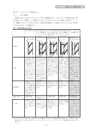
6.10.3 EIFS Testing (IBC/IRC):<br />
6.10.3.1 Tests <strong>for</strong> EIFS are conducted in accordance<br />
with Section 1403.2, Exception 2, of the IBC. At least one<br />
sample <strong>for</strong> each wall envelope assembly configuration is<br />
needed. The configuration is determined by the sheathing,<br />
' insulation, insulation attachment, lamina, openings, joints,<br />
' penetrations <strong>and</strong> wall sill joint configuration used in the test<br />
' samples. Control joints, intersections or terminations of the<br />
' EIFS at dissimilar materials, wall/eave interface,<br />
' configuration <strong>and</strong> methods of making the EIFS at<br />
' penetrations <strong>and</strong> openings waterproof (including the EIFS<br />
' interface at doors <strong>and</strong> windows), as used in the tests, will be<br />
' the basis <strong>for</strong> the evaluation report. Sealants used in the test<br />
' assembly shall comply with Section 4.0. For windows <strong>and</strong><br />
' doors, the test assembly shall be in accordance with Figure<br />
' 1 <strong>and</strong> include the intended flashing system, or the<br />
' evaluation report will need to include dimensioned drawings<br />
' of the type of window <strong>and</strong> door frame used in the tests.<br />
6.10.3.2 Conditions of Acceptance: Conditions of<br />
acceptance are as set <strong>for</strong>th in IBC Section 1403.2,<br />
Exception 2.<br />
6.11 Drainage Test-Drainage-type EIFS:<br />
6.11.1 Testing must be per<strong>for</strong>med in accordance with<br />
EIMA St<strong>and</strong>ard 200.2- St<strong>and</strong>ard Test Method <strong>for</strong><br />
Determining the Drainage Per<strong>for</strong>mance of <strong>Exterior</strong> <strong>Insulation</strong><br />
<strong>and</strong> <strong>Finish</strong> <strong>Systems</strong> (EIFS), Class PB (described in Annex<br />
1). Three samples are required. Each sample panel must be<br />
a minimum of 4 feet by 8 feet (1219 mm by 2438 mm) in<br />
size, with a slot fault measuring 2 inches by 24 inches (50
INTERIM CRITERIA FOR EXTERIOR INSULATION AND FINISH SYSTEMS<br />
mm by 610 mm) positioned 12 inches (305 mm) from the top<br />
of the panel, exposing the weather-resistive barrier. The<br />
sample must be tested <strong>for</strong> 75 minutes.<br />
6.11.2 Conditions of Acceptance: The assemblies must<br />
be capable of draining water, <strong>and</strong> the assemblies must have<br />
an average minimum true drainage efficiency of 90 percent,<br />
except that a minimum of 75 percent may be accepted, with<br />
proper justification, <strong>for</strong> wall assemblies having cementitious<br />
backer units complying with Section 3.6, used as a<br />
sheathing to the exterior of the weather-resistive barriers.<br />
6.12 Accelerated Weathering Test (Weatherometer):<br />
6.12.1 Test Specimens: Five samples are prepared as<br />
<strong>for</strong> the freeze-thaw test (Section 6.5.2), except that sample<br />
size is as necessary to fit the chamber. The back <strong>and</strong> sides<br />
of the sample must be sealed with the appropriate<br />
impervious seal.<br />
6.12.2 Apparatus: Either Section 6.12.2.1 or Section<br />
6.12.2.2 is permitted.<br />
6.12.2.1 ASTM G 23, “Operating Light <strong>and</strong> Water<br />
Exposure Apparatus (Carbon-Arc Type) <strong>for</strong> Exposure of<br />
Nonmetallic Materials” must be used. Model D or DH, with<br />
the operating schedule set <strong>for</strong>th under Method 1, Section 5,<br />
of the referenced ASTM procedure, must be used.<br />
6.12.2.2 ASTM G 26, “Practice <strong>for</strong> Operating Light-<br />
Exposure Apparatus (Xenon Arc-Type) With <strong>and</strong> Without<br />
Water <strong>for</strong> Exposure of Nonmetallic Materials,” Test Method<br />
A, must be used. The exposure apparatus must be Type B<br />
or BH as specified in ASTM G 26, Method A, with a 6,000or<br />
6,500-watt xenon burner tube. Exposure must be <strong>for</strong><br />
2,000 hours, with each cycle consisting of 102 minutes of<br />
light-only exposure <strong>and</strong> 18 minutes of water-spray <strong>and</strong> light<br />
exposure. The water spray must be deionized water. The<br />
spray nozzle must be Type F-80. The apparatus must be<br />
operated with a light exposure of 0.35 W/m 2 at 340 nm. The<br />
test must be per<strong>for</strong>med using a daylight filter system. The<br />
relative humidity <strong>for</strong> the Type BG exposure apparatus must<br />
be 30 ± 5 percent. Black panel temperature must be 145°F<br />
± 5°F (62.7°C ± 2.3°C) during the light-only portion of the<br />
cycle.<br />
6.12.3 Duration: The test must be <strong>for</strong> 2,000 hours.<br />
6.12.4 Conditions of Acceptance: Failure is defined as<br />
surface changes, as viewed by minimum 5× magnification,<br />
such as cracking, checking, crazing, erosion, or other<br />
characteristics that might affect per<strong>for</strong>mance as a wall<br />
cladding.<br />
7.0 APPLICATION<br />
Application instructions bearing the date of publication must<br />
be submitted. Instructions must include the in<strong>for</strong>mation<br />
' noted in Sections 7.1 through 7.6. Installation details need<br />
' to be consistent with assemblies tested under Section<br />
' 6.10.3, as applicable.<br />
7.1 Illustrated details, with the following as a minimum:<br />
7.1.1 Flashing <strong>and</strong>/or sealing around heads, sills <strong>and</strong><br />
jambs of windows <strong>and</strong> doors, <strong>and</strong> at the top of exposed<br />
walls.<br />
7.1.2 Closures <strong>and</strong> flashing at other terminations, such<br />
as eaves <strong>and</strong> sills, <strong>and</strong> at other dissimilar exterior wall<br />
coverings.<br />
9<br />
7.1.3 Typical conditions within the field of the wall<br />
covering, showing substrates <strong>and</strong> control joints.<br />
7.1.4 Parapet at top <strong>and</strong> termination on backside.<br />
7.1.5 Flashing <strong>and</strong>/or sealing at wall penetrations.<br />
7.1.6 Provisions to prevent retention of free water<br />
behind all portions of the EIFS.<br />
7.1.7 Installation over wood-based sheathing.<br />
7.1.8 Other details deemed necessary as conditions of<br />
an evaluation report.<br />
7.2 In<strong>for</strong>mation on any variation from recognized<br />
proportions or content of field-mixed components. See<br />
Sections 3.1 through 3.3.<br />
7.3 Curing instructions.<br />
7.4 Limitations, such as angle of installation <strong>and</strong><br />
installation in interior locations, must be specified.<br />
Architectural treatments that can reduce resistance to water<br />
penetration are prohibited.<br />
7.5 Exposure: For water-resistive coatings <strong>and</strong> insulation<br />
board, the proponent must specify conditions <strong>and</strong> duration<br />
of exposure be<strong>for</strong>e covering.<br />
7.6 IRC: For recognition under the IRC, instructions must<br />
include requirements described in Section R703.9 of the<br />
IRC.<br />
8.0 QUALITY CONTROL<br />
8.1 All foam plastic boards must be listed <strong>and</strong> labeled as<br />
set <strong>for</strong>th in Section 2602.2 of the UBC or 2603.2 of the IBC.<br />
Compliance of foam plastic is based on a current applicable<br />
evaluation report, on the foam plastic; if no such report<br />
exists, foam plastic must comply with the ICC-ES <strong>Interim</strong><br />
<strong>Criteria</strong> <strong>for</strong> Foam Plastic <strong>Insulation</strong> (AC12). The quality<br />
control procedures must also include special requirements<br />
of the EIFS, such as conditioning, dimensional tolerances,<br />
<strong>and</strong> strength. See Section 3.7.<br />
8.2 EIFS Manufacturer: The EIFS manufacturer must<br />
provide to ICC-ES a quality control manual that describes<br />
the in-house testing per<strong>for</strong>med on all incoming raw<br />
materials, <strong>and</strong> on the base coat, finish coat, adhesive, <strong>and</strong><br />
waterproof coating. At a minimum, viscosity, pH level, <strong>and</strong><br />
specific gravity must be tested.<br />
Two quality control systems are acceptable:<br />
1. An in-house quality control system documented in a<br />
manual addressing requirements in this section <strong>and</strong> Section<br />
2.2 of the ICC-ES <strong>Interim</strong> <strong>Criteria</strong> <strong>for</strong> Quality Control<br />
Manuals (AC10); or<br />
2. A quality control system with inspections by an ICBO<br />
ES accredited quality control agency, documented in a<br />
manual addressing requirements in this section <strong>and</strong> the<br />
ICC-ES <strong>Interim</strong> <strong>Criteria</strong> <strong>for</strong> Quality Control Manuals (AC10).<br />
8.3 Field Inspections <strong>and</strong> Reporting:<br />
8.3.1 Installation must be by a contractor recognized by<br />
the proponent as being trained to per<strong>for</strong>m such installations.<br />
A list of the names <strong>and</strong> addresses of recognized contractors<br />
must be maintained by the proponent, <strong>and</strong> must be available<br />
to the building official or ICC-ES upon request.
INTERIM CRITERIA FOR EXTERIOR INSULATION AND FINISH SYSTEMS<br />
8.3.2 An installation card, having the <strong>for</strong>mat shown in<br />
Exhibit A, must be completed by the EIFS contractor <strong>and</strong><br />
must be presented to the building official, with the sealant<br />
installer declaration (such as shown in Exhibit B), at the<br />
completion of each project.<br />
8.3.3 IBC: For recognition under the IBC, special<br />
inspections are required in accordance with Section 1704.1<br />
TABLE 1—CROSS REFERENCE OF STANDARDS EDITIONS<br />
STANDARD 1997 Uni<strong>for</strong>m Building Code 2000 International Building Code ®<br />
10<br />
<strong>and</strong> 1704.12 of the IBC. Duties of the inspector include<br />
verifying field preparation of materials, expiration dates,<br />
installation of components, curing of components,<br />
installation of joints <strong>and</strong> sealants.#<br />
2000 International Residential Code ®<br />
ASTM C 79 1992 1997 1997<br />
ASTM C 150 1994 1997a —<br />
FIGURE 1—CONFIGURATION FOR TESTING WATER PENETRATION RESISTANCE OF OPENING FLASHING SYSTEM
INTERIM CRITERIA FOR EXTERIOR INSULATION AND FINISH SYSTEMS<br />
Completion Date: _______________________________<br />
EXHIBIT A<br />
[SEALANT INSTALLER NAME]<br />
THE SEALANT INSTALLED IN CONJUNCTION WITH AN EXTERIOR INSULATION AND FINISH SYSTEM (EIFS) INSTALLED<br />
ON THE STRUCTURE LOCATED AT THE ADDRESS INDICATED BELOW:<br />
CONFORMS_____<br />
TO [EIFS MANUFACTURER NAME] AND [SEALANT MANUFACTURER'S NAME] RECOMMENDED INSTALLATION<br />
PRACTICES AND SECTION(S) __________ OF ICC-ES, INC., EVALUATION REPORT ER-_______.<br />
Address of Structure: Product Component Names:<br />
______________________________ Primer(s) __________________________________<br />
______________________________ Sealers ___________________________________<br />
______________________________ Bond Breakers _____________________________<br />
______________________________ Sealant Materials____________________________<br />
INSTALLATION CONFORMS<br />
A. Designer's requirements, details <strong>and</strong> instructions ___________<br />
B. Sealant manufacturer's details <strong>and</strong> requirements ___________<br />
C. <strong>Exterior</strong> insulation manufacturer's requirements ___________<br />
D. The in<strong>for</strong>mation entered above is offered in testimony that the Sealant installation con<strong>for</strong>ms with the sealant manufacturer's<br />
installation methods <strong>and</strong> procedures, <strong>and</strong> the EIFS manufacturer's evaluation report.<br />
Sealant Installer Company Name <strong>and</strong> Address:<br />
___________________________________________________<br />
___________________________________________________<br />
___________________________________________________<br />
___________________________________________________<br />
Signature of Responsible Officer: _____________________________________<br />
Typed Name <strong>and</strong> Title of Officer: _____________________________________<br />
Telephone Number: (____) _______________________<br />
cc: Original: Building Department (Must be submitted with EIFS<br />
Copies: EIFS Manufacturer contractor declaration.)<br />
EIFS Contractor<br />
Sealant Manufacturer<br />
11
INTERIM CRITERIA FOR EXTERIOR INSULATION AND FINISH SYSTEMS<br />
Completion Date: _______________________________<br />
EXHIBIT B<br />
[EIFS CONTRACTOR NAME]<br />
THE EXTERIOR INSULATION AND FINISH SYSTEM (EIFS) INSTALLED ON THE STRUCTURE LOCATED AT THE ADDRESS<br />
INDICATED BELOW:<br />
_____ CONFORMS<br />
TO [EIFS MANUFACTURER NAME] RECOMMENDED INSTALLATION PRACTICES AND SECTION (S) _______ OF ICC-ES,<br />
INC., EVALUATION REPORT ER-_______.<br />
Address of Structure: Product Component Names:<br />
________________________________ Adhesive(s) ________________________________<br />
________________________________ Fasteners (mech) ____________________________<br />
________________________________ Base Coat __________________________________<br />
________________________________ Rein<strong>for</strong>cing Fabric ____________________________<br />
<strong>Finish</strong> Coat(s) _______________________________<br />
INSTALLATION CONFORMS<br />
A. Substrate Type <strong>and</strong> Tolerance _______________<br />
B. Weather-resistive Barrier _______________<br />
C. EIFS<br />
1. Adhesive <strong>and</strong>/or Fasteners _______________<br />
2. <strong>Insulation</strong> _______________<br />
3. Rein<strong>for</strong>cing Fabric _______________<br />
4. Base Coat _______________<br />
5. <strong>Finish</strong> _______________<br />
D. The in<strong>for</strong>mation entered above is offered in testimony that the EIFS installation con<strong>for</strong>ms with the EIFS manufacturer's<br />
installation methods <strong>and</strong> procedures, <strong>and</strong> the EIFS manufacturer's ES report.<br />
NOTE: An installation card must be received from the Sealant Installer indicating that the sealant installation con<strong>for</strong>ms with the<br />
EIFS evaluation report <strong>and</strong> sealant manufacturer's installation methods <strong>and</strong> procedures must accompany this declaration. EIFS<br />
Contractor Company Name <strong>and</strong> Address:<br />
________________________________<br />
________________________________<br />
________________________________<br />
________________________________<br />
Signature of Responsible Officer: _____________________________________<br />
Typed Name <strong>and</strong> Title of Officer: _____________________________________<br />
Telephone Number: (____) _______________________<br />
cc: Original: Building Department (Must be submitted with sealant<br />
Copy: EIFS Manufacturer installer declaration.)<br />
12
INTERIM CRITERIA FOR EXTERIOR INSULATION AND FINISH SYSTEMS<br />
1.0 Scope:<br />
ANNEX 1<br />
St<strong>and</strong>ard Test Method <strong>for</strong> Determining the Drainage Per<strong>for</strong>mance of<br />
<strong>Exterior</strong> <strong>Insulation</strong> <strong>and</strong> <strong>Finish</strong> <strong>Systems</strong> (EIFS), Class PB<br />
1.1 This test method determines the drainage per<strong>for</strong>mance of EIFS when subjected to water spray.<br />
1.2 The values stated in SI units in this annex are to be regarded as the st<strong>and</strong>ards. The values given in parenthesis are <strong>for</strong><br />
in<strong>for</strong>mation only.<br />
1.3 This annex does not purport to address all safety concerns, if any, associated with its use. It is the responsibility of the user<br />
of this st<strong>and</strong>ard to establish appropriate safety <strong>and</strong> health practices, <strong>and</strong> to determine the applicability of regulatory<br />
limitations prior to use.<br />
2.0 References:<br />
ASTM E 331—Test Method <strong>for</strong> Water Penetration of <strong>Exterior</strong> Windows, Curtain Walls, <strong>and</strong> Doors by Uni<strong>for</strong>m Static Air Pressure<br />
Difference.<br />
3.0 Definitions:<br />
3.1 Specimen B: The entire assembled unit submitted <strong>for</strong> testing as described in Section 7.<br />
3.2 Water Drainage: The ability of the specimen to drain water at the interface of the drainage plane <strong>and</strong> the weather-resistive<br />
barrier.<br />
3.3 Drainage Efficiency: A percentage value based on the amount of water sprayed into the test specimen versus the amount<br />
of water that passed through the test specimen <strong>and</strong> was collected.<br />
3.4 Test Specimen Slot Fault: A cut-out in the test specimen, into which water spray is directed.<br />
4.0 Summary of Test Method:<br />
This test method consists of sealing the test specimen into or against one face of a test chamber, <strong>and</strong> concentrating a water<br />
spray into the fault of the test specimen.<br />
5.0 Significance <strong>and</strong> Use:<br />
This test method is a st<strong>and</strong>ard procedure <strong>for</strong> determining the per<strong>for</strong>mance <strong>and</strong> the drainage efficiency of an EIFS clad wall<br />
system.<br />
6.0 Apparatus:<br />
6.1 Test Chamber: See Figures 1 <strong>and</strong> 2. A test chamber or box with an opening, a removable mounting panel, or one open side<br />
in which or against which the specimen is installed <strong>and</strong> sealed.<br />
6.2 Water-spray System: The water spray system must deliver water spray directly into the slot fault at a minimum rate of 3.4<br />
L/m 2 � min (5.0 U.S. gal./ft. 2 h). This rate is based on the area of the slot fault, based on net dimensions.<br />
6.2.1 Conversion of Volume Flow Rate to Weight of Water Delivered:<br />
6.2.1.1 Calibrate the water spray system to be within the specified rate.<br />
6.2.1.2 Collect the water from the calibrated water-spray system in a tared container <strong>for</strong> a period of 15 minutes. Weigh the<br />
collected water. Multiply the weight of the collected water by 5.0. The result is defined as the water delivered to the<br />
test specimen.<br />
13
INTERIM CRITERIA FOR EXTERIOR INSULATION AND FINISH SYSTEMS<br />
7.0 Test Specimen:<br />
ANNEX 1—(Continued)<br />
7.1 The EIFS clad wall test specimen must be a minimum of 1220 mm (width) by 2440 mm (height) (4 feet by 8 feet)<br />
7.2 The test specimen must be prepared as follows:<br />
7.2.1 EIFS Drainage Test Specimen:<br />
7.2.1.1 The EIFS drainage specimen must consist of wood or steel framing with a sheathing substrate, a weather-resistive<br />
barrier, <strong>and</strong> the EIFS manufacturer's drainage system. The test specimen must be prepared using the same materials,<br />
details, <strong>and</strong> methods of anchoring as used in actual construction.<br />
7.2.1.2 A 51-millimeter-high-by-610-millimeter-wide (2 inches by 24 inches) slot fault must be cut out of the insulation board<br />
<strong>and</strong> the lamina at a distance of 304 mm (1 foot) from the top of the test specimen, so that the weather-resistive barrier<br />
is exposed. The slot fault must be centered on the panel.<br />
7.2.1.3 The EIFS coatings must be allowed to cure <strong>for</strong> a minimum of 28 days prior to testing.<br />
8.0 Test Procedure:<br />
8.1 Photograph the test setup.<br />
8.2 Mount a clear acrylic plastic spray box measuring 622 mm by 241 mm by 184 mm (24 1 / 2 inches by 9 1 / 2 inches by 7 1 / 4 inches)<br />
flush over the 50.8-millimeter-high-by-610-millimeter-wide (2 inches by 24 inches) slot fault. The spray box is mounted at<br />
an angle to ensure that all water is directed into the slot fault.<br />
8.3 Two spray nozzles must be installed in the spray box. The nozzles must be located 12.7 mm ( 1 / 2 inch) from the front edge<br />
of the spray box, <strong>and</strong> 127 mm (5 inches) to the right <strong>and</strong> to the left of center.<br />
8.4 A pressure regulator, a flow meter, <strong>and</strong> an inline water filter attached to the spray box nozzles must control the volume of<br />
water sprayed into the slot fault. This distribution of water must provide a water spray equivalent to 3.4 L/m 2 �min. (5.0 U.S.<br />
gal./ft. 2 �h) or 1.44 L/75 minutes (2.12 gal./75 minutes), +10% - 0%. Determination of the total amount of water applied to<br />
the test specimen during the test duration must be accurate to within 1%.<br />
8.5 Mount <strong>and</strong> seal the test specimen to the test chamber with the slot fault level.<br />
8.6 Collect the drained water in a tared container. The empty container must be weighed to the nearest 10 g (0.35 oz.). The<br />
container must be placed at the base of the test specimen in order to weigh the drained water at various intervals as<br />
described in Section 8.8.<br />
8.7 Begin water spray, <strong>and</strong> time <strong>for</strong> 75 minutes.<br />
8.8 Weigh the collected water at 15-minute intervals (five times during the test period).<br />
8.9 Terminate the water spray.<br />
8.10 Allow the test specimen to drain <strong>for</strong> 60 minutes, then weigh the collected water.<br />
9.0 Report:<br />
9.1 Report the following in<strong>for</strong>mation:<br />
9.1.1 Date of test <strong>and</strong> date of report.<br />
14
INTERIM CRITERIA FOR EXTERIOR INSULATION AND FINISH SYSTEMS<br />
ANNEX 1—(Continued)<br />
9.1.2 Identification of test specimen (manufacturer, materials, construction, dimensions, <strong>and</strong> other pertinent in<strong>for</strong>mation).<br />
9.1.3 Detailed drawings of the test specimen that provide a description of the EIFS being tested.<br />
9.1.4 A statement that describes the rate of water spray.<br />
9.1.5 The weight of water, collected at 15-minute intervals.<br />
9.1.6 The total weight of the water sprayed into the slot fault.<br />
9.1.7 The drainage efficiency of the test specimen.<br />
9.1.8 Note any leakage through the back of the test specimen.<br />
EIFS Specimen Drainage Efficiency = × 100%<br />
15
INTERIM CRITERIA FOR EXTERIOR INSULATION AND FINISH SYSTEMS<br />
Figures 1 <strong>and</strong> 2 detail typical schematic diagrams of the test equipment used in the test.<br />
WINDOWS<br />
CHAMBER<br />
SPRAY BOX<br />
PRESSURE<br />
RELIEF<br />
VALVE<br />
TO<br />
SPRAY<br />
BOX<br />
WASTE<br />
GATE<br />
FIGURE 1—RIGHT SIDE VIEW<br />
SHUT-OFF<br />
VALVE<br />
FIGURE 2—REAR VIEW<br />
16<br />
MANOMETER<br />
WATER<br />
PRESSURE<br />
GAUGE<br />
PANEL<br />
T · HANDLE<br />
WATER TANK<br />
DRAIN BASIN<br />
PRESSURE<br />
REGULATOR<br />
BLOWER