

SMD High Frequency Power Inductor Designed for VRD & VRM 10.x ...
SMD High Frequency Power Inductor Designed for VRD & VRM 10.x ...
SMD High Frequency Power Inductor Designed for VRD & VRM 10.x ...

You also want an ePaper? Increase the reach of your titles
YUMPU automatically turns print PDFs into web optimized ePapers that Google loves.
<strong>SMD</strong> <strong>High</strong> <strong>Frequency</strong> <strong>Power</strong> <strong>Inductor</strong><br />
<strong>Designed</strong> <strong>for</strong> <strong>VRD</strong> & <strong>VRM</strong> <strong>10.x</strong> & 11.x Applications<br />
FEATURES<br />
Recommended <strong>for</strong> use with all major Voltage<br />
Regulator ICs<br />
<strong>High</strong> Current handling capability in the<br />
smallest footprint<br />
Up to 2MHz operating frequency<br />
Extended operating temperature range: -40C to<br />
125C<br />
Robust <strong>SMD</strong> package capable of handling the<br />
most aggressive SMT assembly process<br />
RoHS compliant version available<br />
100% tested to a 10% DCR tolerance<br />
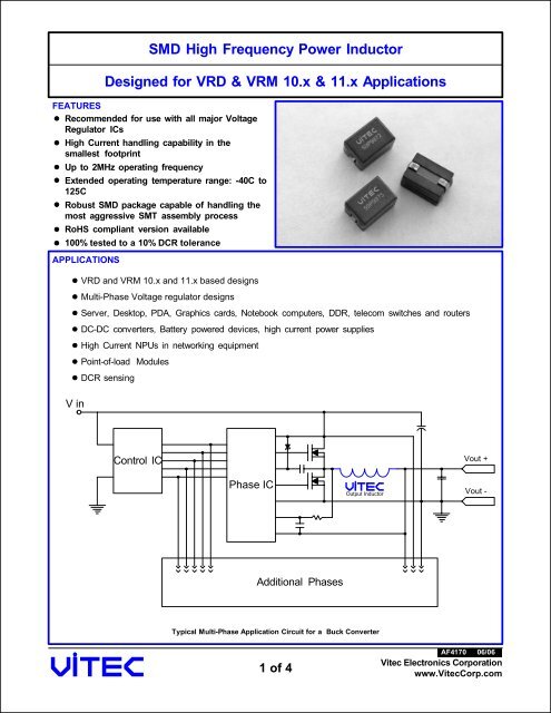
APPLICATIONS<br />
V in<br />
<strong>VRD</strong> and <strong>VRM</strong> <strong>10.x</strong> and 11.x based designs<br />
Multi-Phase Voltage regulator designs<br />
Server, Desktop, PDA, Graphics cards, Notebook computers, DDR, telecom switches and routers<br />
DC-DC converters, Battery powered devices, high current power supplies<br />
<strong>High</strong> Current NPUs in networking equipment<br />
Point-of-load Modules<br />
DCR sensing<br />
Control IC<br />
Phase IC<br />
Additional Phases<br />
Typical Multi-Phase Application Circuit <strong>for</strong> a Buck Converter<br />
1 of 4<br />
Output <strong>Inductor</strong><br />
AF4170<br />
Vout +<br />
Vout -<br />
06/06<br />
Vitec Electronics Corporation<br />
www.VitecCorp.com
PACKAGE<br />
<strong>SMD</strong> <strong>High</strong> <strong>Frequency</strong> <strong>Power</strong> <strong>Inductor</strong><br />
<strong>Designed</strong> <strong>for</strong> <strong>VRD</strong> & <strong>VRM</strong> <strong>10.x</strong> & 11.x Applications<br />
Dimensions: Inches [mm]. Tolerances: +/- 0.005" [0,13mm] unless otherwise noted<br />
ELECTRICAL CHARACTERISTICS @ 25 o C (unless otherwise noted)<br />
Classic<br />
59P9872<br />
Part<br />
Number<br />
2 of 4<br />
SCHEMATIC<br />
1<br />
2<br />
SUGGESTED PCB LAYOUT<br />
0.160<br />
[4,06]<br />
0.100<br />
[2,54]<br />
0.140<br />
(2 PL.)<br />
[3,56]<br />
Drawing NOT to scale<br />
Inductance<br />
@ Irated4 Irated1 Inductance<br />
@ 0Adc<br />
DCR<br />
4 Saturation Current2 Temp.<br />
Rise<br />
nH<br />
ADC<br />
25 MAX<br />
Factor<br />
O Temp.<br />
Rise<br />
Current<br />
nH<br />
MAX<br />
mOhm<br />
C<br />
3<br />
-40OC 125O Application<br />
Inductance<br />
nH<br />
± 15% MIN<br />
+/-10%<br />
ADC ADC ADC<br />
C<br />
ADC<br />
59P9871 59PR9871 120 120 82 76 .470 78 76 74 33 0.0232<br />
59P9873 59PR9873 230 230 156 44 .470 45 41 31 33 0.0469<br />
59P9874<br />
59P9875<br />
59P9876<br />
0.283 [7,20]<br />
MAX<br />
0.005 [0,13]<br />
2 PLS<br />
RoHS<br />
59PR9872<br />
59PR9874<br />
59PR9875<br />
59PR9876<br />
1<br />
0.430 [10,92]<br />
MAX<br />
59P987x<br />
xxxxS<br />
0.300 [7,62]<br />
150<br />
300<br />
400<br />
510<br />
150<br />
300<br />
400<br />
510<br />
2<br />
0.100 [2,5]<br />
2 PLS<br />
102<br />
204<br />
272<br />
346<br />
64<br />
31<br />
23<br />
17<br />
0.295 [7,50]<br />
MAX<br />
0.061 [1.55]<br />
Notes:<br />
1 - The rated current is the saturation current @ 25oC. 2 - The I(Saturation) is the current at which the inductance drops by 20% maximum of its value at 0ADC. This current is measured at the<br />
stated ambient environment and by applying a short duration pulse current to the component, minimizing the self-heating effects.<br />
3 - The I(Temp. Rise) is the current at which the temperature of the part increases by a maximum of 50oC. This test is per<strong>for</strong>med with the<br />
part mounted on a PCB with 0.250" wide, 0.004" thick copper traces and applying the DC current <strong>for</strong> a minimum of 30 minutes.<br />
4 - Inductance is measured at 100 KHz and 1.0 Vrms.<br />
5 - The additional Temperature Rise due to <strong>High</strong> ET (Voltage x Time) can be estimated using the following <strong>for</strong>mula:<br />
DCR Loss = Idc2 Trise (<br />
2 I<br />
+<br />
x .470<br />
2<br />
O 0.833<br />
1.84<br />
2.2<br />
Core Loss + DCR Loss<br />
Core Loss = 0.0054 x ( F ) x (Temp. Rise Factor x I )<br />
C) =<br />
4.83<br />
I = Delta I across the inductor<br />
F = Switching <strong>Frequency</strong> (kHz)<br />
AF4170<br />
0.0293<br />
0.0586<br />
0.0781<br />
0.0996<br />
Add an "R" to the part number after "P" <strong>for</strong> the RoHS compliant version (i.e. 59PR9871 is the RoHS compliant version of 59P9871).<br />
.470<br />
.470<br />
.470<br />
.470<br />
66<br />
32<br />
24<br />
18<br />
70<br />
31<br />
23<br />
17<br />
68<br />
23<br />
17<br />
13<br />
33<br />
33<br />
33<br />
33<br />
06/06<br />
Vitec Electronics Corporation<br />
www.VitecCorp.com
Inductance (nH)<br />
Inductance (nH) Inductance (nH)<br />
Temperature Rise ( o C)<br />
<strong>SMD</strong> <strong>High</strong> <strong>Frequency</strong> <strong>Power</strong> <strong>Inductor</strong><br />
<strong>Designed</strong> <strong>for</strong> <strong>VRD</strong> & <strong>VRM</strong> <strong>10.x</strong> & 11.x Applications<br />
59P9871 Inductance vs. Idc @ 25 o C<br />
59P9873 Inductance vs. Idc @ 25 o C<br />
59P987X Temp. Rise vs. Idc<br />
3 of 4<br />
59P9872 Inductance vs. Idc @ 25 o C<br />
DC Bias (ADC) DC Bias (ADC)<br />
DC Bias (ADC)<br />
59P9874 Inductance vs. Idc @ 25 o C<br />
59P9875 Inductance vs. Idc @ 25 o C 59P9876 Inductance vs. Idc @ 25 o C<br />
DC Bias (ADC)<br />
Inductance (nH)<br />
Inductance (nH)<br />
Inductance (nH)<br />
Resistance (Ohms)<br />
DC Bias (ADC)<br />
DC Bias (ADC)<br />
59P987X Rdc vs. Temp. Rise<br />
IDC (A) Temperature ( o C)<br />
AF4170<br />
06/06<br />
Vitec Electronics Corporation<br />
www.VitecCorp.com
IR Profile<br />
Temp ( o C)<br />
240<br />
217<br />
200<br />
170<br />
100<br />
0<br />
<strong>SMD</strong> <strong>High</strong> <strong>Frequency</strong> <strong>Power</strong> <strong>Inductor</strong><br />
<strong>Designed</strong> <strong>for</strong> <strong>VRD</strong> & <strong>VRM</strong> <strong>10.x</strong> & 11.x Applications<br />
ABOUT US<br />
Vitec Electronics Corporation, founded in 1986, is a worldwide leader in the design, manufacture and sale of magnetic<br />
solutions. Vitec's market focus includes the power, power conditioning, telecom, networking, communications and<br />
computing. Vitec has also established strong alliances with chip manufacturers whereby magnetic solutions are<br />
designed in conjunction with unique silicon requirements and are offered as reference designs by the chip companies.<br />
With its Corporate Headquarters and Research & Development center located in Carlsbad, Cali<strong>for</strong>nia, and its state of<br />
the art manufacturing facility and material sourcing in China, Vitec is uniquely positioned to supply the latest<br />
technology at the lowest cost. Vitec offers both standard and custom product design capabilities with all of its facilities<br />
being ISO certified.<br />
COMMITMENT<br />
VITEC Electronics empowers each of its employees by providing a business environment that encourages a<br />
commitment to excellence, a sense of ownership and personal accountability to all Vitec Customers.<br />
Competitive Pricing, Quality Products, and On Time Deliveries are expected from today’s World Class Magnetics<br />
Suppliers. The high standards of today’s customer are strengthening the dedication and commitment of VITEC<br />
Electronics to provide Total Customer Service.<br />
CONTACT US<br />
USA<br />
Peak Temperature 240 o C<br />
60 120 180 240 300 360<br />
Time (Seconds)<br />
ENVIRONMENTAL & RELIABILITY DATA<br />
VITEC ELECTRONICS CORPORATION<br />
6213 El Camino Real<br />
Carlsbad, CA 92009<br />
U.S.A.<br />
TEL: +1 (760) 918-8831<br />
FAX: +1 (760) 918-8840<br />
Rate of Rise:<br />
2-3C / Sec Max.<br />
Pre-Heat:<br />
150C / 90 Sec Max.<br />
Soak:<br />
150-170C / 60-90<br />
Sec<br />
Time Above 217C:<br />
45-75 Sec<br />
Cooldown:<br />
4C Max. / Sec<br />
Storage Temperature: -40C to +125C<br />
Operating Temperature: -40C to +125C<br />
Resistance to Solder Reflow: 3 passes thru. +235C <strong>for</strong> 30<br />
seconds minimum<br />
ASIA<br />
4 of 4<br />
Tape and Reel<br />
QUALITY POLICY<br />
Vitec will provide products and services that meet or exceed our Customer's requirements, con<strong>for</strong>m to company<br />
policies and standards, and exhibit continuously improving levels of Quality.<br />
C<br />
SHANGHAI VITEC ELECTRONICS CO., LTD.<br />
3369 He Chuan Road<br />
Min Hang District, Shanghai, 201103<br />
China<br />
TEL: +86 (21) 6446-4828<br />
FAX: +86 (21) 6446-4865<br />
P<br />
User Direction of Feed<br />
AF4170<br />
W<br />
Carrier Dimensions:<br />
P= 0.472/12,00 (inch/mm)<br />
C= 0.453/11,50 (inch/mm)<br />
W=0.945/24,00 (inch/mm)<br />
Quantity per Reel: 650 pcs<br />
Reel Size: 13 inches<br />
63-224A1<br />
Marking permanency: Tested per JESD22-B107-A<br />
Solderability: Tested per MIL-STD-750D<br />
Life Test: Tested per MIL-STD-202F, Method 108A<br />
Thermal Cycle: Tested per JESD22-B104-B, Test Condition G<br />
06/06<br />
Vitec Electronics Corporation<br />
www.VitecCorp.com