


Create successful ePaper yourself
Turn your PDF publications into a flip-book with our unique Google optimized e-Paper software.
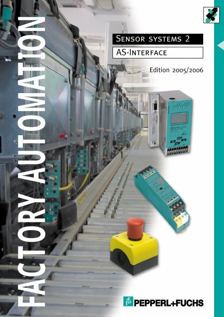
FACTORY AUTOMATION<br />
<strong>Sensor</strong> <strong>systems</strong> 2<br />
<strong>AS</strong>-<strong>Interface</strong><br />
Edition 2005/2006
<strong>AS</strong>-<strong>Interface</strong> - References<br />
6<br />
<strong>AS</strong>-<strong>Interface</strong> has made a breakthrough on a wide front in automotive technology.<br />
And the examples given below of typical applications illustrate how<br />
<strong>AS</strong>-<strong>Interface</strong> is also employed by well-known manufacturers in many other<br />
branches of industry.<br />
Automotive industry:<br />
The floor and overhead suspended conveyor system in the new Rüsselsheim<br />
plant of OPEL AG has been completely automated using <strong>AS</strong>-<strong>Interface</strong>.<br />
Over one hundred <strong>AS</strong>-<strong>Interface</strong> gateways and over one thousand <strong>AS</strong>-<br />
<strong>Interface</strong> modules are used to process the signals from several thousand<br />
sensors and encoders. A remarkable feature of this plant is the throughgoing<br />
production line without buffer <strong>systems</strong>, requiring the <strong>AS</strong>-<strong>Interface</strong> network<br />
to be constructed in segments, using sliding contacts. The overall<br />
length of this system is well over one kilometre. The transfer and assignment<br />
functions via the sliding contacts demonstrate once again the robustness<br />
and reliability of <strong>AS</strong>-<strong>Interface</strong>.<br />
Chemical and process technology:<br />
Paint manufacture and the subsequent filling of the products is the core<br />
business of the Herberts Lacke Company. The demands of the automated<br />
production plant concept include the provision of safeguards in the potentially<br />
explosive areas. <strong>AS</strong>-<strong>Interface</strong> modules with ATEX approval for Zone 1<br />
are daily proving their value in these critical applications.<br />
Storage and mechanical handling:<br />
Plant sections involving logic networks are simply controlled via <strong>AS</strong>-<strong>Interface</strong>.<br />
Thanks to the comprehensive diagnostic functions, problems can be<br />
quickly and precisely located, even in extensive <strong>systems</strong>, leading to the reduction<br />
of downtime and rationalisation of plant servicing.<br />
These attributes prompted Viastore Systems GmbH to select <strong>AS</strong>-<strong>Interface</strong><br />
in numerous high-bay racking stores projects. In another application in<br />
2003, Roche Diagnostik collaborated with Aberle Steuerungstechnik GmbH<br />
in pallet and container handling technology featuring <strong>AS</strong>-<strong>Interface</strong>.<br />
Plant construction:<br />
As a renowned constructor of filling plant, Krones has for some time successfully<br />
incorporated the <strong>AS</strong>-<strong>Interface</strong> concept into its projects. This has<br />
allowed decentralised plant components to be controlled on a modular basis<br />
and networked together with ease. Here, high quality, long life and great<br />
flexibility are the attractive <strong>AS</strong>-<strong>Interface</strong> features.<br />
Food and beverage industry:<br />
In breweries - and as here, in the dispensing of drinks - Feige GmbH uses<br />
<strong>AS</strong>-<strong>Interface</strong> to control flows via the open/close operation of valves. Wellproven<br />
solutions are available for the open structure, as are pcb solutions<br />
for box installation and also integrated solutions for solenoid valves.<br />
Component manufacture:<br />
In order to reduce the amount of cabling required and to provide adequate<br />
flexibility for alternating production lines, <strong>AS</strong>-<strong>Interface</strong> is frequently employed<br />
to control the handling sequences, as illustrated here on an SMD assembly<br />
plant. As a rule the Emergency-Stop buttons are also integrated into<br />
the <strong>AS</strong>-<strong>Interface</strong> Safety at Work concept, so as to avoid dual cabling.<br />
Subject to reasonable modifications due to technical advances. Copyright Pepperl+Fuchs, Printed in Germany<br />
Pepperl+Fuchs Group • Tel.: Germany +49 621 776-0 USA +1 330 4253555 Singapore +65 67799091 Internet http://www.pepperl-fuchs.com<br />
Issue date 2004-11-19 - Catalogue <strong>AS</strong>-<strong>Interface</strong> 2004/2005
Issue date 2004-11-19 - Catalogue <strong>AS</strong>-<strong>Interface</strong> 2004/2005<br />
<strong>AS</strong>-<strong>Interface</strong> - Table of contents<br />
1 Introduction .........................................................................................................................8<br />
1.1 What is <strong>AS</strong>-<strong>Interface</strong>? ........................................................................................................................................8<br />
1.2 The decisive advantages of <strong>AS</strong>-<strong>Interface</strong> ..........................................................................................................8<br />
1.3 Components in the <strong>AS</strong>-<strong>Interface</strong> system .........................................................................................................11<br />
1.4 <strong>AS</strong>-<strong>Interface</strong> specification 2.1 ..........................................................................................................................16<br />
1.5 Configuration and installation of a system with <strong>AS</strong>-<strong>Interface</strong> in 4 steps ..........................................................20<br />
2 Masters and Gateways .....................................................................................................23<br />
2.1 Master..............................................................................................................................................................24<br />
2.2 Gateways .........................................................................................................................................................24<br />
2.3 Programming with <strong>AS</strong>-i Control Tools ..............................................................................................................24<br />
3 Power Supplies, Power Extenders and Repeaters.........................................................57<br />
3.1 Overview of power supplies, power extenders, and repeaters ........................................................................59<br />
4 <strong>AS</strong>-<strong>Interface</strong> - Safety at work ...........................................................................................81<br />
4.1 The safety concept...........................................................................................................................................82<br />
4.2 The advantages ...............................................................................................................................................82<br />
4.3 Safety monitor..................................................................................................................................................83<br />
4.4 Safe slaves ......................................................................................................................................................84<br />
4.5 The <strong>AS</strong>IMON configuration software ...............................................................................................................84<br />
4.6 Overivew of available <strong>AS</strong>-<strong>Interface</strong> Safety at Work products ..........................................................................85<br />
5 Coupling modules...........................................................................................................107<br />
5.1 Switch cabinet and junction box modules......................................................................................................108<br />
5.2 Field modules.................................................................................................................................................150<br />
5.3 Analogue modules .........................................................................................................................................193<br />
5.4 Ex Modules ....................................................................................................................................................207<br />
5.5 AirBox (Pneumatic Module) ...........................................................................................................................216<br />
5.6 Display and control modules..........................................................................................................................221<br />
5.7 Printed circuit board module ..........................................................................................................................221<br />
5.8 Engine starter ................................................................................................................................................221<br />
6 Inductive <strong>AS</strong>-<strong>Interface</strong> <strong>Sensor</strong>s.....................................................................................237<br />
7 Photoelectric <strong>AS</strong>-<strong>Interface</strong> <strong>Sensor</strong>s..............................................................................255<br />
8 <strong>AS</strong>-<strong>Interface</strong> Rotary Encoder .........................................................................................273<br />
9 Accessories.....................................................................................................................307<br />
10 Mating connectors and cable.........................................................................................337<br />
11 <strong>AS</strong>-<strong>Interface</strong> Training Kit ................................................................................................345<br />
12 Additional Information....................................................................................................346<br />
12.1 Glossary.........................................................................................................................................................346<br />
12.2 <strong>AS</strong>-<strong>Interface</strong> type codes (without modules and accessories) ........................................................................348<br />
12.3 Type code for I/O modules / analogue modules ............................................................................................349<br />
12.4 Type code for cable sockets ..........................................................................................................................350<br />
12.5 Type codes for connector cables....................................................................................................................350<br />
12.6 Pepperl+Fuchs GmbH worldwide ..................................................................................................................352<br />
13 Alphabetical list of types................................................................................................358<br />
Subject to reasonable modifications due to technical advances. Copyright Pepperl+Fuchs, Printed in Germany<br />
Pepperl+Fuchs Group Tel.: Germany +49 621 776-0 USA +1 330 4253555 Singapore +65 67799091 Internet http://www.pepperl-fuchs.com<br />
7
<strong>AS</strong>-<strong>Interface</strong> - Introduction<br />
8<br />
1 Introduction<br />
1.1 What is <strong>AS</strong>-<strong>Interface</strong>?<br />
The Actuator-<strong>Sensor</strong> <strong>Interface</strong> (<strong>AS</strong>-<strong>Interface</strong>) is the replacement for conventional<br />
wiring technology on the sensor-actuator level.<br />
<strong>AS</strong>-<strong>Interface</strong> ensures secure, extremely EMC resistant data transmission,<br />
minimises installation time and costs, includes a diagnostic function and detects<br />
short circuits and other conditions, reduces maintenance costs, enables<br />
the simple decentralisation of control processes, increases the transparency<br />
of a system, makes any kind of upgrade particularly simple and<br />
flexible, and guarantees high availability.<br />
<strong>AS</strong>-<strong>Interface</strong> is not a proprietary system, but rather an open standard which<br />
is available on the market from many manufacturers in a wide range of versions.<br />
1.2 The decisive advantages of <strong>AS</strong>-<strong>Interface</strong><br />
The Actuator-<strong>Sensor</strong>-<strong>Interface</strong> (<strong>AS</strong>-<strong>Interface</strong>) is optimised for the reliable<br />
transfer of small volumes of data under harsh industrial conditions and for<br />
economic reasons it has become the tried and tested standard for the networking<br />
of sensors and actuators in many applications.<br />
In conventional wiring two cores per sensor and actuator are typically required<br />
for the power supply and a further core for the signal or control cable.<br />
The power supply, for example, can be laid in parallel via splitter boxes, but<br />
the input and output signals must be looped via distribution devices and laid<br />
to PLC cards. This leads to high costs for the method of connection/distribution,<br />
involves much time on installation and, in addition, the wiring must<br />
be documented in detail.<br />
Subject to reasonable modifications due to technical advances. Copyright Pepperl+Fuchs, Printed in Germany<br />
Pepperl+Fuchs Group Tel.: Germany +49 621 776-0 USA +1 330 4253555 Singapore +65 67799091 Internet http://www.pepperl-fuchs.com<br />
Issue date 2004-11-19 - Catalogue <strong>AS</strong>-<strong>Interface</strong> 2004/2005
Issue date 2004-11-19 - Catalogue <strong>AS</strong>-<strong>Interface</strong> 2004/2005<br />
Actuator <strong>Sensor</strong> <strong>Interface</strong><br />
<strong>AS</strong>-<strong>Interface</strong> - Introduction<br />
In comparison, <strong>AS</strong>-<strong>Interface</strong> offers the following advantages:<br />
Two-core cable for data and power transfer to all devices.<br />
Connection using the insulation penetration technique for I/O stations<br />
saves time, since the operations involving the stripping of insulation and<br />
the application of cable sleeves are eliminated.<br />
In the PLCs the I/O assemblies are replaced by the <strong>AS</strong>-<strong>Interface</strong> master<br />
and the assignment is no longer carried out by fixed addressing of the I/O<br />
cards, but by free assignment via the master.<br />
Diagnostic options via the <strong>AS</strong>-<strong>Interface</strong> enable faults to be quickly eliminated<br />
and down time reduced.<br />
Ground faults and duplicate addressing can be detected and displayed.<br />
If "intelligent" sensors are employed, the display of stability control, remote<br />
parameter assignment, mode of operation reversal and standby indication<br />
functions can be used. The function diagnosis can decisively<br />
increase plant availability.<br />
By using <strong>AS</strong>-<strong>Interface</strong> masters with integrated PLC functionality, control<br />
processes can be stored as programs in the master and self-standing<br />
PLCs can be dispensed with completely. This allows response times of<br />
only a few milliseconds to be achieved.<br />
Due to the reduced requirement for wiring, less cable ducting is required.<br />
Costs are also reduced because of the space saved in the control cabinet<br />
due to the elimination of I/O assemblies.<br />
The free topology makes system planning and installation particularly<br />
simple, so that it can be extended at any time.<br />
Conventional<br />
I/O assembly<br />
Decentralized I/O assemblies<br />
PLC PLC PLC<br />
24 V DC<br />
e.g. INTERBUS-S<br />
PROFIBUS DP<br />
I/O assembly I/O assembly<br />
These <strong>AS</strong>-<strong>Interface</strong> advantages lead to cost savings in planning, commissioning<br />
and maintenance.<br />
By using interface modules up to 248 binary sensors and 186 binary actuators<br />
can be operated on a single <strong>AS</strong>-<strong>Interface</strong> network. The following limiting<br />
values apply to a fully implemented system for both <strong>AS</strong>-<strong>Interface</strong> specifications:<br />
Master/Gateway - Specification 2.0:<br />
max. 124 binary sensors and 124 binary actuators.<br />
Master/Gateway - Specification 2.1:<br />
max. 248 binary sensors and 186 binary actuators.<br />
Subject to reasonable modifications due to technical advances. Copyright Pepperl+Fuchs, Printed in Germany<br />
Pepperl+Fuchs Group Tel.: Germany +49 621 776-0 USA +1 330 4253555 Singapore +65 67799091 Internet http://www.pepperl-fuchs.com<br />
24 V DC<br />
24 V DC<br />
9
<strong>AS</strong>-<strong>Interface</strong> - Introduction<br />
10<br />
Master<br />
Master<br />
Master<br />
Data Protection<br />
The interference resistance of data transmission is an important parameter<br />
for the networking of sensors and actuators in an industrial environment.<br />
Due to the special type of coding (Manchester Code APM, Alternating Pulse<br />
Modulation) and the continual monitoring of signal quality, <strong>AS</strong>-<strong>Interface</strong><br />
achieves such a high level of data protection, that the system is also suitable<br />
for safety applications.<br />
This is not affected by the absence of screening on the transfer cable. Tests<br />
on a welding robot and a galvanising plant showed that the <strong>AS</strong>-<strong>Interface</strong><br />
system was not affected by these levels of external interference. This is<br />
possible due to the symmetrical signal transfer, which filters out interference.<br />
Network hierarchy and topology<br />
<strong>AS</strong>-<strong>Interface</strong> is designed for the lowest level of the automation hierarchy<br />
and offers a simple, safe and fast transfer at an optimum cost/effectiveness<br />
ratio. The system topology can take the form of a line, star, tree, or ring<br />
structure. For information which is not time-critical and for the achievement<br />
of longer transfer paths, <strong>AS</strong>-<strong>Interface</strong> can be connected via gateways to<br />
higher level <strong>systems</strong> such as PROFIBUS, InterBus, EtherNet TCP/IP, DeviceNet,<br />
Modbus, Modbus+, CCLink, CANopen, etc. <strong>AS</strong>-<strong>Interface</strong> masters<br />
with serial RS 232 interfaces and integrated PLC functionality provide a distributed<br />
stand-alone solution. In this way the control system is unloaded<br />
and, in addition, cycle times of, for example, 2 ms are achieveable when the<br />
<strong>AS</strong>-<strong>Interface</strong> network is not fully populated. This solution is directly aligned<br />
with the trend towards the decentralised construction of control units. The<br />
advantages are:<br />
simpler and faster expansion possibilities and also the commissioning of<br />
sub-domains,<br />
shorter cable connections and less data communication on the higherlevel<br />
field bus,<br />
reduction of down time due to the autonomously operating sub-domains<br />
and<br />
shorter and clearer programs.<br />
Subject to reasonable modifications due to technical advances. Copyright Pepperl+Fuchs, Printed in Germany<br />
Pepperl+Fuchs Group Tel.: Germany +49 621 776-0 USA +1 330 4253555 Singapore +65 67799091 Internet http://www.pepperl-fuchs.com<br />
Issue date 2004-11-19 - Catalogue <strong>AS</strong>-<strong>Interface</strong> 2004/2005
Issue date 2004-11-19 - Catalogue <strong>AS</strong>-<strong>Interface</strong> 2004/2005<br />
K5<br />
K20<br />
G4<br />
KF<br />
PCI<br />
<strong>AS</strong>-<strong>Interface</strong> - Introduction<br />
1.3 Components in the <strong>AS</strong>-<strong>Interface</strong> system<br />
Products from Pepperl+Fuchs are certified by independent <strong>AS</strong>-<strong>Interface</strong><br />
testing authorities. This ensures that the products satisfy the <strong>AS</strong>-<strong>Interface</strong><br />
specification and can be operated without problem in a system together with<br />
other certificated <strong>AS</strong>-<strong>Interface</strong> products, including those from other manufacturers.<br />
This is indicated by the shadowed logo on the data sheets.<br />
Masters and Gateways<br />
The core of the <strong>AS</strong>-<strong>Interface</strong> system is the Master (serial connection via<br />
RS 232) and the Gateway (master with an interface to the commonly used<br />
field buses). Earlier programming by PC or PLC can continue to be utilised,<br />
for example, with an S7-400 with a standard I/O data range, since <strong>AS</strong>-<strong>Interface</strong><br />
behaves as an I/O card. The devices control and monitor the data exchange<br />
with the modules and <strong>AS</strong>-<strong>Interface</strong> sensors/actuators on the Master-Slave<br />
principle. However, as seen from the field bus, the gateway behaves<br />
as a slave or station node, with typically more than 32 bytes of input/output<br />
data and also with additional analogue channels and management<br />
channels.<br />
Master/Gateways are available in the form of plug-in cards for a PC, as control<br />
cabinet devices and as field devices. The masters/gateways include a<br />
diagnostic function with the following monitoring functions:<br />
Configuration errors: Deviation between existing slaves and configured<br />
addresses,<br />
Peripheral faults: Loss of function of one or more slaves,<br />
Communication faults: Incorrect transfer of several messages,<br />
Detection and display of duplicate addressing and ground faults (on K20<br />
series),<br />
Safety diagnosis: Separate presentation of the safe slaves and display of<br />
the diagnostic function of the monitor.<br />
<strong>AS</strong>-<strong>Interface</strong> power packs (2 A to 8 A, with 30.5 V and data decoupling)<br />
are used for the power supply. Repeaters and Power Extenders allow the<br />
power supply to be decentralised and cable length to be extended to over<br />
100 m. The repeater galvanically isolates the primary and secondary sides,<br />
in order to provide a reduced probability of failure in the case of a short circuit.<br />
A number of repeaters can be operated in a star formation, their<br />
number being limited only by the input resistance at the <strong>AS</strong>-<strong>Interface</strong>. However,<br />
it is only possible to operate a maximum of 2 repeaters in series. Together<br />
with the repeater, an <strong>AS</strong>-<strong>Interface</strong> power supply is required for the<br />
power supply of the other <strong>AS</strong>-<strong>Interface</strong> circuit.<br />
Subject to reasonable modifications due to technical advances. Copyright Pepperl+Fuchs, Printed in Germany<br />
Pepperl+Fuchs Group Tel.: Germany +49 621 776-0 USA +1 330 4253555 Singapore +65 67799091 Internet http://www.pepperl-fuchs.com<br />
11
<strong>AS</strong>-<strong>Interface</strong> - Introduction<br />
VariKont L<br />
12<br />
G2<br />
G4<br />
G6<br />
KE1<br />
G5<br />
RL28<br />
<strong>AS</strong>-<strong>Interface</strong> slaves<br />
Intelligent sensors/actuators<br />
Either "intelligent" sensors/actuators with integrated <strong>AS</strong>-<strong>Interface</strong> chip, or<br />
modules, are connected to the masters/gateways. Pepperl+Fuchs offers a<br />
wide range of "intelligent" sensors.<br />
Modules<br />
Modules are <strong>AS</strong>-<strong>Interface</strong> stations to which standard sensors/actuators can<br />
be connected. <strong>AS</strong>-<strong>Interface</strong> modules are available as a control cabinet solution<br />
and as field modules with protection to IP67. Analogue values with up<br />
to 16 bits can be automatically transferred to the higher level field bus via<br />
analogue modules within a max. of 35 ms.<br />
The control cabinet modules in the KF and KF2 series are 20 mm or<br />
40 mm (4EA modules) wide and offer plug-in terminals as well as power rail<br />
connections for fast, simple installation in the control cabinet. These KF<br />
modules are only available as standard slaves in specification 2.0. The<br />
newer version in the KE series is available as an A/B slave according to<br />
specification 2.1.<br />
The terminal housing module in the K3 series is flat (39 mm) and thus tailored<br />
to terminal housing requirements. The outputs are supplied externally<br />
and 3-wire sensors can also be connected. The KE1 series, which is only<br />
50 mm high and 22.5 mm wide, offers connections for up to 4 two-wire inputs<br />
and 2 externally-supplied electronic outputs.<br />
In the case of the field modules the G2 series is available with a plug-in<br />
connection via M12, the G6 series with a plug-in connection via M8 and the<br />
G4 series with cable gland and cage-clamp terminals in different housing<br />
sizes.<br />
Connection of the G2 modules is achieved directly by attaching the flat <strong>AS</strong>-<br />
<strong>Interface</strong> cable in the respective base portion. In the G4 series it is possible<br />
to make the <strong>AS</strong>-<strong>Interface</strong> connection via round cable. Series G6 is connected<br />
via a 4-pin M12 plug connector 4 (<strong>AS</strong>-<strong>Interface</strong> and 24 V auxiliary power).<br />
Analogue modules for switching cabinet and field use transmit analogue<br />
input and output values for current and voltage as well as the analogue values<br />
from PT100 thermocouples without additional programming. In this<br />
case it is necessary to use a master/gateway to Specification 2.1.<br />
G5 series modules are in the device category (1)2G and are therefore approved<br />
for hazardous areas in Zone 1 in accordance with ATEX. The <strong>AS</strong>-<br />
<strong>Interface</strong> cable is therefore installed in increased safety and the connection<br />
is carried out in accordance with EN 50019. The module electronics are encapsulated<br />
and intrinsically safe inputs and outputs are available. NAMUR<br />
sensors in accordance with the requirements of IEC 60947-5-6 (DIN 19234,<br />
NAMUR) can be connected to the inputs.<br />
Safe modules are available in the G4, G2 and KE1 versions for field and<br />
junction box or control cabinets. The devices are TÜV-certified according to<br />
EN 954-1 and IEC 61508.<br />
Further information can be found in the chapters on the modules.<br />
Subject to reasonable modifications due to technical advances. Copyright Pepperl+Fuchs, Printed in Germany<br />
Pepperl+Fuchs Group Tel.: Germany +49 621 776-0 USA +1 330 4253555 Singapore +65 67799091 Internet http://www.pepperl-fuchs.com<br />
Issue date 2004-11-19 - Catalogue <strong>AS</strong>-<strong>Interface</strong> 2004/2005
Issue date 2004-11-19 - Catalogue <strong>AS</strong>-<strong>Interface</strong> 2004/2005<br />
VBP-HH1<br />
Software<br />
<strong>AS</strong>-<strong>Interface</strong> - Safety at Work<br />
- for safety-relevant applications<br />
<strong>AS</strong>-<strong>Interface</strong> - Introduction<br />
Safety-relevant components, such as emergency-stop buttons, safety light<br />
grids and safety door locking mechanisms, can be integrated, based on the<br />
identical technology and protocol. This only requires the installation of a<br />
safety monitor and safe slaves in the network. Mixed operation of safe<br />
and non-safe <strong>AS</strong>-<strong>Interface</strong> slaves is possible without problem. The monitor<br />
has the function of monitoring the data communication on the <strong>AS</strong>-<strong>Interface</strong><br />
cable.<br />
The safe slaves are used to transfer dynamic code sequences (8 x 4 bit data<br />
sequence), which are stored in each slave. These are "learned" during<br />
the installation of the monitor. During operation, the monitor compares the<br />
target and actual sequences on each cycle. If the alarm code "0000“ is<br />
transmitted or a departure from the set sequence is established (e. g. due<br />
to the failure of a device or a communication fault), the safety monitor<br />
switches off safely within 40 ms. Switch-on again takes 100 ms. Up to two<br />
shut-off circuits can be implemented per monitor.<br />
The available slaves are safe field and control cabinet modules and an<br />
Emergency-Stop button with an integrated <strong>AS</strong>-<strong>Interface</strong> chip.<br />
Bus communication and the data protocol have been evaluated as safe by<br />
the BIA and the technology has been certified by TÜV. According to<br />
EN 954-1, the maximum safety category 4 is reached, and can be used for<br />
stop category 0 (immediate power-off) and 1 (controlled power-off). In accordance<br />
with IEC 61508 approval, up to SIL 3 can be attained.<br />
Hand-held and Software Tools<br />
<strong>AS</strong>-<strong>Interface</strong> slaves from Pepperl+Fuchs are usually addressed using a<br />
VBP-HH1 hand-held programming device over an addressing connector.<br />
With the hand-held device, the following can be performed very quickly and<br />
simply on-site:<br />
Isolation of the <strong>AS</strong>-<strong>Interface</strong> slave from the <strong>AS</strong>-<strong>Interface</strong> network,<br />
power supply of the <strong>AS</strong>-<strong>Interface</strong> via the hand-held device,<br />
address assignment for the <strong>AS</strong>-<strong>Interface</strong> slave,<br />
setting of outputs for function testing, even without PLC.<br />
Separate disconnection of the master in the control cabinet or modification<br />
of the <strong>AS</strong>-<strong>Interface</strong> power supply is not necessary.<br />
With the hand-held, an entire <strong>AS</strong>-<strong>Interface</strong> network can also be addressed<br />
through the <strong>AS</strong>-<strong>Interface</strong> cable if the master is inactive.<br />
Easy-to-use software tools are available for system parameter assignment<br />
using a PC. The <strong>AS</strong>-<strong>Interface</strong> control tools render parameter assignment a<br />
very simple procedure and the <strong>AS</strong>IMON software is used to assign parameters<br />
to the safety-related components.<br />
Subject to reasonable modifications due to technical advances. Copyright Pepperl+Fuchs, Printed in Germany<br />
Pepperl+Fuchs Group Tel.: Germany +49 621 776-0 USA +1 330 4253555 Singapore +65 67799091 Internet http://www.pepperl-fuchs.com<br />
13
<strong>AS</strong>-<strong>Interface</strong> - Introduction<br />
14<br />
conventional<br />
<strong>AS</strong>-<strong>Interface</strong><br />
Flat cable<br />
<strong>AS</strong>-<strong>Interface</strong> installation<br />
If <strong>AS</strong>-<strong>Interface</strong> modules are used in the control cabinet or junction boxes,<br />
connection via power rail is particularly advantageous.<br />
Flat cable<br />
When using <strong>AS</strong>-<strong>Interface</strong> in the field, the greatest advantages are realised<br />
when flat cable is used. However, a 2-core, unscreened standard round cable<br />
with 1.5 mm2 cross section (for example, H05VV-F2x1,5) can be used.<br />
Due to the form of the flat cable, polarity reversal is impossible, and using<br />
insulation penetration connection, slaves can be connected in seconds. For<br />
this purpose, the flat cable is laid in two cable trays in the lower part of the<br />
module and the upper part of the module is then positioned on it and<br />
screwed down. This ensures both strain relief and also a secure contact via<br />
two contact blades per core.<br />
A 24 V auxiliary power supply is necessary only for very high-powered actuators,<br />
and can be supplied via a black flat cable which is laid parallel to<br />
the yellow <strong>AS</strong>-<strong>Interface</strong> flat cable.<br />
Installation<br />
The <strong>AS</strong>-<strong>Interface</strong> cable is symmetrical, that is, neither of the two cores may<br />
be earthed. A branch can be made at any point (arbitrary topology), on the<br />
end of which no termination resistor is necessary.<br />
The total length of the <strong>AS</strong>-<strong>Interface</strong> network can be extended from 100 m<br />
by an additional 100 m using repeaters.<br />
Power supply is generally incorporated using the <strong>AS</strong>-<strong>Interface</strong> power at any<br />
point in the <strong>AS</strong>-<strong>Interface</strong> network. For slaves with particularly large power<br />
requirements, it makes sense to put the power supply nearby, to keep the<br />
voltage drop low. An optional 24 V auxiliary power supply may be necessary<br />
when using high-powered actuators, in order to be able to drive these via<br />
the electronic outputs.<br />
<strong>AS</strong>-<strong>Interface</strong> masters/gateways are supplied with 24 V directly or from the<br />
<strong>AS</strong>-<strong>Interface</strong>.<br />
Commissioning can be performed directly at the master/gateway using<br />
function keys and the graphical display, a PC or PLC are not required.<br />
The attachment of a new slave is "plug and play": Connection, "teach-in" on<br />
the master, done. The addressing of the same type of slave is automatic after<br />
an exchange. Slaves can be connected or disconnected while the network<br />
is in use.<br />
The connection of sensors and actuators to the interface module is completed<br />
using plug connectors, screw terminals, or cage-clamp terminals. Inputs,<br />
that is, sensors or mechanical contacts, can be supplied with power from<br />
the <strong>AS</strong>-<strong>Interface</strong>.<br />
Pepperl+Fuchs offers a wide variety of connection accessories for simple<br />
installation (for instance, cable gland in M12 or terminals, screw adaptors<br />
for housing installation) and of course various types of <strong>AS</strong>-<strong>Interface</strong> flat cable.<br />
A tool for the quick stripping of flat cable is also available.<br />
Subject to reasonable modifications due to technical advances. Copyright Pepperl+Fuchs, Printed in Germany<br />
Pepperl+Fuchs Group Tel.: Germany +49 621 776-0 USA +1 330 4253555 Singapore +65 67799091 Internet http://www.pepperl-fuchs.com<br />
Issue date 2004-11-19 - Catalogue <strong>AS</strong>-<strong>Interface</strong> 2004/2005
Issue date 2004-11-19 - Catalogue <strong>AS</strong>-<strong>Interface</strong> 2004/2005<br />
<strong>AS</strong>-<strong>Interface</strong> - Introduction<br />
Power Rail<br />
For the control cabinet, there are either distributor terminals as sub-distributors<br />
to the control cabinet modules, power supply, and master, or alternatively<br />
the use of units with integrated Power Rail connections. There are two<br />
different types of Power Rail: PR-05 and UPR-05.<br />
In the PR-05, there is a 50 cm long inset component in the 35 mm tophat<br />
rail per EN 50022. The PR-05 has a 20 mm mounting grid and can be shortened<br />
in 40 mm increments. The PR-05 can be extended using appropriate<br />
adaptors (VE-PR).<br />
The UPR-05 is a gridless Universal Power Rail, which is supplied in lengths<br />
of 2 m and can be shortened at any point. Included in the delivery package,<br />
besides the rail itself, are the C-rail, a cover plate for mechanical and electrical<br />
protection of the inset component, and 2 end caps. If the modules are<br />
vertically mounted, an end terminal (for instance TS35 type 2) should be<br />
used to prevent the module from slipping down.<br />
PR-05 UPR-05<br />
The operating principle of both types of Power Rail is the same. Five conductors<br />
are integrated into the insert component, of which two are used for<br />
the transmission of the <strong>AS</strong>-<strong>Interface</strong> signal. If a module or the master/gateway<br />
is connected to the <strong>AS</strong>-<strong>Interface</strong> line, this node applies the <strong>AS</strong>-<strong>Interface</strong><br />
signal to the Power Rail conductors. All other modules are then connected<br />
to the <strong>AS</strong>-<strong>Interface</strong> line by snapping them onto the tophat rail. Modules<br />
are snapped onto the rail vertically from above.<br />
More notes about the <strong>AS</strong>-<strong>Interface</strong>,<br />
configuring the installation, and many example applications<br />
can be found in the book "<strong>AS</strong>-<strong>Interface</strong> -<br />
Compendium“, available from Pepperl+Fuchs<br />
Subject to reasonable modifications due to technical advances. Copyright Pepperl+Fuchs, Printed in Germany<br />
Pepperl+Fuchs Group Tel.: Germany +49 621 776-0 USA +1 330 4253555 Singapore +65 67799091 Internet http://www.pepperl-fuchs.com<br />
15
<strong>AS</strong>-<strong>Interface</strong> - Introduction<br />
16<br />
62<br />
Spec 2.1<br />
1.4 <strong>AS</strong>-<strong>Interface</strong> specification 2.1<br />
Functional description of the<br />
<strong>AS</strong>-<strong>Interface</strong> specification 2.1<br />
With the <strong>AS</strong>-<strong>Interface</strong> specification 2.1, which was defined in 1999 by the<br />
<strong>AS</strong>-<strong>Interface</strong> Association as a backwards-compatible extension retaining<br />
the protocol and physical parameters, significant advantages for the user<br />
were introduced:<br />
Number of nodes increased from 31 standard slaves to<br />
62 A/B slaves,<br />
enhanced diagnostic function with peripheral error bit,<br />
simple analogue value transmission with internal data handling,<br />
extension of the ID codes of the nodes.<br />
Devices in accordance with specification 2.1 are denoted on data sheets<br />
with this symbol.<br />
62 nodes on <strong>AS</strong>-<strong>Interface</strong> network<br />
To take advantage of these possibilities, a VB... Master/Gateway is needed.<br />
Standard slaves (as in specification 2.0), thanks to backwards compatibility,<br />
can still be connected to a new master using specification 2.1. However,<br />
two of the 62 possible addresses are occupied by one standard slave. The<br />
use of A/B Slaves on an "old" master is possible, by always setting the select<br />
bit to logical "0". Despite this, we don't recommend it, since a change to<br />
this bit will change the address, and it may thus be impossible to talk to the<br />
slave due to such a configuration error.<br />
The master message is almost unchanged in the specification 2.1. The only<br />
change is that the select bit "SEL" is transmitted in what used to be the<br />
fourth output bit "I3", which in addition to the address bits A0 ... A4 enables<br />
the extended A/B addressing.<br />
Each address can therefore be split into A and B addresses, i.e. in addresses<br />
15A and 15B.<br />
Since the fourth output bit is now used as an additional address bit, only 3<br />
output bits per slave can now be transmitted, that is, per <strong>AS</strong>-<strong>Interface</strong> network<br />
3* 62 = 186 output bits are set. The slave response remains unchanged,<br />
and there are now 4 * 62 = 248 bits of input data available.<br />
Standard slaves can easily be used with a "new" VB... master, however, the<br />
following changes apply:<br />
A standard slave occupies both A and B addresses and thus reduces the<br />
maximum number of nodes by one.<br />
Standard slaves on a "new" VB... master/gateway are recognised using<br />
the identification code (ID code) and can still have 4 output data bits.<br />
Analogue modules and safe modules occupy a full address, even if these<br />
devices are designed to specification 2.1. This allows the response time of<br />
these modules to be kept to a minimum.<br />
Subject to reasonable modifications due to technical advances. Copyright Pepperl+Fuchs, Printed in Germany<br />
Pepperl+Fuchs Group Tel.: Germany +49 621 776-0 USA +1 330 4253555 Singapore +65 67799091 Internet http://www.pepperl-fuchs.com<br />
Issue date 2004-11-19 - Catalogue <strong>AS</strong>-<strong>Interface</strong> 2004/2005
Issue date 2004-11-19 - Catalogue <strong>AS</strong>-<strong>Interface</strong> 2004/2005<br />
FAULT<br />
PWR<br />
A D<br />
Spec 2.1<br />
Diagnostic function with peripheral error<br />
<strong>AS</strong>-<strong>Interface</strong> - Introduction<br />
Besides communications disturbances (i.e. erroneous messages), the master<br />
can also detect hardware errors which occur on the slave. These peripheral<br />
error messages can be used to power down <strong>systems</strong> in case of error,<br />
since sensor signals may no longer be safely available. It is also possible<br />
simply to evaluate stored data statistically in the master under "LFS" (list of<br />
faulted slaves), in order to evaluate system safety. A red LED display is located<br />
on the slave. This simplifies the location and correction of errors. An<br />
extended diagnostic also makes it possible to locate even sporadically occurring<br />
problems with configuration and communications and evaluate<br />
them with the <strong>AS</strong>-i Control Tools. This information can be processed in the<br />
PLC using the command interface and for instance then displayed in clear<br />
text to the operator on a remote display.<br />
Analogue transmission<br />
The <strong>AS</strong>-<strong>Interface</strong> protocol allows the transmission of 4 bits in one cycle.<br />
With the analogue profile S7.3, seven messages can be collected in the<br />
master within only 35 ms, and output as a 16-bit analogue value. This was<br />
only possible using an application program in specification 2.0. The output<br />
of analogue control values as 0 V ... 10 V or 4 mA ... 20 mA signals is possible.<br />
Extension of ID codes:<br />
A/B slaves have ID codes = A hex , while standard slaves have a different ID<br />
code of A hex . So as to distinguish the different profiles (types of slave), two<br />
further identification codes were introduced, the ID1 code and the ID2 code.<br />
The IO code and the ID2 code describe the profile of the A/B slaves completely<br />
and are permanently stored in the slave.<br />
Transfer rate and cycle time<br />
The bit transmission rate of the <strong>AS</strong>-<strong>Interface</strong> is about 167 kBaud, in order<br />
to make the system very resistant to cable reflexions and errors even with<br />
complex topologies, while still eliminating the need for termination resistors.<br />
The cycle time is, however, a deciding factor for small quantities of data.<br />
When fully loaded, masters on specification 2.0 (31 slaves or 124 binary<br />
sensors + 124 binary actuators) have a maximum cycle time of 5 ms, and<br />
masters on specification 2.1 in extended mode (62 slaves, or 248 binary<br />
sensors + 186 binary actuators) have a maximum cycle time of 10 ms. The<br />
cycle time can be shortened by reducing the number of nodes or by addressing<br />
A/B slaves in standard mode. Every unoccupied slave address<br />
saves 150 µs. This makes the <strong>AS</strong>-<strong>Interface</strong> one of the fastest bus <strong>systems</strong>.<br />
In a mixed system with standard slaves and A/B slaves, standard slaves are<br />
interrogated on each cycle and A/B slaves every other cycle. On the nth cycle,<br />
all A slaves are addressed, and on the n+1-th cycle, all the B slaves.<br />
The master can use the configuration to detect which addresses are unoccupied<br />
and doesn't interrogate these at all. If only one (either A or B) address<br />
is assigned to an A/B slave on the <strong>AS</strong>-<strong>Interface</strong> network, then these<br />
slaves are interrogated on every cycle. The frequency of interrogation can<br />
be increased in this way.<br />
Subject to reasonable modifications due to technical advances. Copyright Pepperl+Fuchs, Printed in Germany<br />
Pepperl+Fuchs Group Tel.: Germany +49 621 776-0 USA +1 330 4253555 Singapore +65 67799091 Internet http://www.pepperl-fuchs.com<br />
17
<strong>AS</strong>-<strong>Interface</strong> - Introduction<br />
Master call<br />
Slave response<br />
18<br />
The <strong>AS</strong>-<strong>Interface</strong> bus protocol<br />
The <strong>AS</strong>-<strong>Interface</strong> message is constructed in a very compact way. For the<br />
user, this all occurs in the background, and it is presented here only to give<br />
you a better understanding of data transmission.<br />
The slave response, always 7 bits long after the 14-bit master query, takes<br />
the following form:<br />
SB CB A4 A3 A2 A1 A0 I4 SEL I2 I1 I0 PB EB<br />
1 start bit (SB, always "0")<br />
1 control bit (CB)<br />
5 address bits (A0 ... A4) plus SEL bit for A/B address for expansion to 62<br />
slaves<br />
5 data bits (I0, I1, I2, I4)<br />
1 parity bit (PB)<br />
1 end bit (EB, always "1")<br />
The <strong>AS</strong>-<strong>Interface</strong> master uses the control bit to tell the slave whether this<br />
message is a command (i.e. read I/O configuration, read ID code, etc.) or a<br />
data or parameter call.<br />
Together with the SEL bit, the 5 address bits denote the slave being addressed.<br />
With 5+1 Bits, 64 nodes can be addressed. Address 0 must always<br />
be unoccupied, since it is used for automatic addressing after an exchange.<br />
Thus up to 62 slaves can be addressed.<br />
In a data or parameter call (CB = "0"), the I4 bit is used to distinguish between<br />
I4 = "0" ==> parameter call<br />
I4 = "1" ==> data call<br />
.<br />
The bits I0 ... I2 contain the output data, by which up to 3 outputs can be<br />
controlled or 3 parameter bits transmitted. The entire message is secured<br />
with a parity bit and is concluded with an end bit. In specification 2.0 (standard<br />
mode) the I3 bit was available as a fourth output bit, which is now used<br />
as select bit (SEL) when extended-mode addressing is in operation. If<br />
slaves built to specification 2.1 can be operated in standard mode, the I3 bit<br />
can also be used as an output bit.<br />
In the slave response, besides the 4 bits of input data, only the start bit (SB),<br />
the parity bit (PB), and the end bit (EB) are transmitted.<br />
SB I3 I2 I1 I0 PB EB<br />
The master cyclically interrogates the unique addresses (1A, 1B, 2A, 2B,<br />
3A...31A, 31B) of all slaves in turn in a polling process. The addresses in<br />
use are stored in the master's configuration. It only queries these existing<br />
addresses, which shortens the cycle time correspondingly.<br />
Subject to reasonable modifications due to technical advances. Copyright Pepperl+Fuchs, Printed in Germany<br />
Pepperl+Fuchs Group Tel.: Germany +49 621 776-0 USA +1 330 4253555 Singapore +65 67799091 Internet http://www.pepperl-fuchs.com<br />
Issue date 2004-11-19 - Catalogue <strong>AS</strong>-<strong>Interface</strong> 2004/2005
Issue date 2004-11-19 - Catalogue <strong>AS</strong>-<strong>Interface</strong> 2004/2005<br />
Parameters<br />
Summary of parameters<br />
<strong>AS</strong>-<strong>Interface</strong> - Introduction<br />
Topology: Arbitrary: Line, star, tree, etc.<br />
Number of nodes: 62 <strong>AS</strong>-<strong>Interface</strong> slaves<br />
(max. 4 x 62 binary inputs<br />
and 3 x 62 outputs)<br />
Access method: Master/Slave<br />
Address assignment: Via master, with addressing unit, or automatically<br />
upon exchange<br />
Cable: Unshielded two-conductor cable,<br />
round cable 2 x 1.5 mm 2 or<br />
<strong>AS</strong>-<strong>Interface</strong> flat cable 2 x 1.5 mm 2<br />
Network length: 100 m overall length<br />
with 2 repeaters up to a max. of 300 m between<br />
master and end of bus cable,<br />
in star topology larger overall length with additional<br />
repeaters<br />
Transfer rate: approx. 167 kBit/sec<br />
Cycle time: max. 10 ms with 62 A/B slaves<br />
El. interface: Data transfer:<br />
APM with sin2 pulses<br />
Power supply: approx. 30.5 V DC,<br />
max. 8 A total current<br />
Auxiliary power: 24 V DC, max. 8 A<br />
Bit encoding: Manchester<br />
Data/message: 4 bits bidirectional<br />
Data security: Signal quality monitoring +<br />
1 parity bit, corresponds to HD = 4 (Hamming Distance)<br />
Subject to reasonable modifications due to technical advances. Copyright Pepperl+Fuchs, Printed in Germany<br />
Pepperl+Fuchs Group Tel.: Germany +49 621 776-0 USA +1 330 4253555 Singapore +65 67799091 Internet http://www.pepperl-fuchs.com<br />
19
<strong>AS</strong>-<strong>Interface</strong> - Introduction<br />
20<br />
STEP 1<br />
STEP 2<br />
1.5 Configuration and installation of a system<br />
with <strong>AS</strong>-<strong>Interface</strong> in 4 steps<br />
Does the system size fit?<br />
The number of inputs and outputs needed must fit the number of <strong>AS</strong>-<strong>Interface</strong><br />
networks. With a full load of 62 4E3A modules, 248 inputs and 186 outputs<br />
within an <strong>AS</strong>-<strong>Interface</strong> network are possible. If, however, due to local<br />
system layout, not all the input or outputs on a slave are used, or if analogue<br />
modules or standard slaves are connected, the number of addresses is reduced,<br />
since these slaves "use up" an entire address. If safety-related components<br />
are integrated, these must be connected to safe slaves, which also<br />
require an entire address. If the diagnostics of the safety monitor need to be<br />
interrogated at the master, then the monitor must also be assigned a full address.<br />
In time-critical applications, the B address can be left free, so that the<br />
A-addressed slave can be interrogated on every cycle, this allows a cycle<br />
time < 5 ms (instead of < 10 ms) even at full load. These rules influence the<br />
possible number of total inputs and outputs.<br />
If the number of nodes on one <strong>AS</strong>-<strong>Interface</strong> network is insufficient, then a<br />
double master can also be used to drive two <strong>AS</strong>-<strong>Interface</strong> networks. Masters/gateways<br />
installed in parallel in the control cabinet can also enable simple<br />
fulfilment of the required system size. If signals from one <strong>AS</strong>-<strong>Interface</strong><br />
network need to be transferred to a second one, data coupler modules can<br />
be used, which transfer 4 bits at a time from one network to the other.<br />
In extensive installations, line lengths of over 100m (this includes spur lines<br />
to intelligent sensors) may be necessary. By using repeaters (maximum of<br />
2 in series), the length of the line can be extended to up to 300 m from the<br />
master. One or two additional power supplies (or power extenders) will be<br />
necessary. A network with star topology, with more repeaters, can attain<br />
very large overall line lengths. The topology of the network is arbitrary: Star,<br />
tree, line, spur lines, or other.<br />
Specifying the power supply<br />
The power supply needed can be derived from the power consumption of<br />
the individual devices. The following typical values can be used:<br />
Current consumption by the master: approx. 200 mA<br />
Per <strong>AS</strong>-<strong>Interface</strong> module: approx. 30 mA … 80 mA<br />
(depending on type)<br />
Per sensor input: approx. 5 mA<br />
Per sensor: ca. 10 mA … 80 mA (depending<br />
on type)<br />
(inductive typically 10 mA,<br />
optical typically 35 mA)<br />
Per analogue module: approx. 80 mA<br />
Per safety monitor (1/2 channel): 150/200 mA<br />
This makes it possible to estimate whether a 2.8 A, a 4 A or an 8 A <strong>AS</strong>-<strong>Interface</strong><br />
power supply will be necessary. Exact power consumption data can<br />
be found in the corresponding data sheets.<br />
If a 24 V auxiliary power supply is also necessary, the power consumptions<br />
must also be totalled for it, and a corresponding 24 V power supply selected.<br />
Subject to reasonable modifications due to technical advances. Copyright Pepperl+Fuchs, Printed in Germany<br />
Pepperl+Fuchs Group Tel.: Germany +49 621 776-0 USA +1 330 4253555 Singapore +65 67799091 Internet http://www.pepperl-fuchs.com<br />
Issue date 2004-11-19 - Catalogue <strong>AS</strong>-<strong>Interface</strong> 2004/2005
Issue date 2004-11-19 - Catalogue <strong>AS</strong>-<strong>Interface</strong> 2004/2005<br />
STEP 3<br />
STEP 4<br />
<strong>AS</strong>-<strong>Interface</strong> - Introduction<br />
Address configuration of slaves and wiring<br />
It is possible to configure the addressing of slaves at your desk or workbench<br />
using the VBP-HH1 hand-held device, label them, and then install in<br />
the planned locations. This has the advantage, that the addressing and labeling<br />
can be performed rationally. However, it is then very important to<br />
take care to match addresses to functions during installation. This procedure<br />
is generally to be recommended.<br />
If modules are first installed and then connected by flat cable to the <strong>AS</strong>-<strong>Interface</strong><br />
line, addressing and labeling must be performed with the hand-held<br />
device in a second step, since all slaves have address 0 as delivered. It is<br />
important to ensure that no addresses are duplicated.<br />
The addressing of intelligent sensors with integrated <strong>AS</strong>-<strong>Interface</strong> chips can<br />
easily be performed by plugging the sensors into the hand-held device. Appropriate<br />
contact pins are integrated for M12, VariKont M and VariKont designs.<br />
Modules with addressing jacks are connected via a connector cable.<br />
The slave is thus disconnected from the network and other modules and<br />
can only be accessed through the hand-held device.<br />
The hand-held device can also be used for reassigning addresses on the<br />
<strong>AS</strong>-<strong>Interface</strong> network. The master must simply be disconnected from the<br />
network and the hand-held device connected to the yellow <strong>AS</strong>-<strong>Interface</strong> cable.<br />
All nodes on the network can then be addressed selectively. There is<br />
the additional possibility of performing addressing directly on the master using<br />
the display, or using the <strong>AS</strong>-i Control Tools software.<br />
After all modules have been addressed and connected, the <strong>AS</strong>-<strong>Interface</strong> flat<br />
cable is connected to the <strong>AS</strong>-<strong>Interface</strong> power supply, and the 24 V auxiliary<br />
power supply optionally connected. The master and any other control cabinet<br />
modules should be wired in parallel. Adaptors from flat cable to flexible<br />
leads, or Power Rail technology, may be used to do this.<br />
Neither the <strong>AS</strong>-<strong>Interface</strong> positive or negative may be earthed at any point!<br />
Only the earth connection of the power supply may be connected to earth.<br />
To ensure correct earthing, we offer power supplies and gateways with<br />
earth monitoring functions.<br />
Configuration of masters/gateways<br />
Finally, it must be defined in the master/gateway which nodes are connected<br />
to the <strong>AS</strong>-<strong>Interface</strong> network. This is done by pressing the MODE button<br />
on the front of the gateway for about 5 seconds (switching into configuration<br />
mode) and then pressing the MODE button again (switches back to protected<br />
operating mode). Alternatively, on masters with graphical displays, the<br />
"Quick setup" menu can be called up for configuration. After successful configuration<br />
of the master/gateway, the red "Config. Error" LED will be turned<br />
off.<br />
Field bus master simulators are available for PROFIBUS, CANopen, DeviceNET.<br />
and ModBus. EtherNet and Interbus gateways can be simulated<br />
using the <strong>AS</strong>-<strong>Interface</strong> Control Tools and tested including the higher-order<br />
field bus connection.<br />
Subject to reasonable modifications due to technical advances. Copyright Pepperl+Fuchs, Printed in Germany<br />
Pepperl+Fuchs Group Tel.: Germany +49 621 776-0 USA +1 330 4253555 Singapore +65 67799091 Internet http://www.pepperl-fuchs.com<br />
21
Masters and<br />
Gateways<br />
Power Supplies,<br />
Extender, Repeaters<br />
Safety at work<br />
I/O Modules<br />
Control cabinet<br />
I/O Modules<br />
Field application<br />
Analogue modules<br />
Other modules<br />
Inductive sensors<br />
Photoelectric<br />
sensors<br />
Rotary encoders<br />
Accessories<br />
<strong>AS</strong>-<strong>Interface</strong> - Introduction<br />
22<br />
Subject to reasonable modifications due to technical advances. Copyright Pepperl+Fuchs, Printed in Germany<br />
Pepperl+Fuchs Group Tel.: Germany +49 621 776-0 USA +1 330 4253555 Singapore +65 67799091 Internet http://www.pepperl-fuchs.com<br />
Issue date 2004-11-19 - Catalogue <strong>AS</strong>-<strong>Interface</strong> 2004/2005
Issue date 2004-11-19 - Catalogue <strong>AS</strong>-<strong>Interface</strong> 2004/2005<br />
2 Masters and Gateways<br />
<strong>AS</strong>-<strong>Interface</strong> - Introduction<br />
The <strong>AS</strong>-lnterface Masters / Gateways are the core components of an <strong>AS</strong>-<br />
<strong>Interface</strong> system. These devices perform a cyclic interrogation of the slaves<br />
via a polling procedure and represent the link to the higher level system in<br />
the form of a decentrally operating, flexible and fast control unit. The devices<br />
are also available with a control function (Integrated PLC with inputs, outputs,<br />
timers, and counters) for autonomous operation.<br />
Masters are available in various versions and construction types, for example<br />
with a large graphics display for on-site diagnosis. These cover not only<br />
peripheral faults, even statistical faults can be evaluated via an internal fault<br />
counter and used for trouble-shooting if necessary.<br />
Of course, all data can also be transferred via the field bus interface for control<br />
purposes.<br />
Addressing and parameter assignment (On initial installation, for example)<br />
can take place directly on the master/gateway. There are also commissioning<br />
tools available, for instance the <strong>AS</strong>-i Control Tools software, VAZ-SW-<br />
ACT32. This software package allows simple, quick, and easy commissioning<br />
of the <strong>AS</strong>-<strong>Interface</strong> network via the serial interface of a PC.<br />
Various interfaces are available for connecting the higher level control system:<br />
Serial interface (RS 232)<br />
PCI bus for direct connection to a PC<br />
Field bus interface with the gateways (For all current field bus <strong>systems</strong>,<br />
e. g. PROFIBUS DP, DeviceNet, INTERBUS, etc.)<br />
A gateway consists of two parts:<br />
The <strong>AS</strong>-<strong>Interface</strong> master (e. g. to <strong>AS</strong>-<strong>Interface</strong> specification V2.1) for<br />
management of the <strong>AS</strong>-<strong>Interface</strong> network.<br />
The interface to the higher level field bus system (e. g. as PROFIBUS<br />
slave) for transfer of the data to the control system.<br />
For field applications Pepperl+Fuchs can supply masters/gateways in<br />
protection class IP67 in the G4 housing. These devices are ideal for decentralisation<br />
with <strong>AS</strong>-<strong>Interface</strong>, since the devices can be installed close to the<br />
application. The restriction to 100 m of cable is of no great consequence<br />
and the large distances can be bridged using the higher level field bus system.<br />
The unified menu structure and philosophy of the masters/gateways simplifies<br />
operation despite a large number of devices.<br />
Master/Gateways designed to specification 2.1 have the type codes VBM...<br />
oder VBG..., while devices designed to specification 2.0 have the codes<br />
VAM... or VAG...<br />
Devices with codes VBG-...-D oder VBG-...-DMD are equipped with a large<br />
graphics display for extra ease of operation.<br />
For your peace of mind:<br />
This <strong>AS</strong>-<strong>Interface</strong> logo indicates that the <strong>AS</strong>-<strong>Interface</strong> devices are "Certificated"<br />
products. It's there to reassure you that you will experience no negative<br />
mutual interference effects from <strong>AS</strong>-<strong>Interface</strong> devices in your system.<br />
Subject to reasonable modifications due to technical advances. Copyright Pepperl+Fuchs, Printed in Germany<br />
Pepperl+Fuchs Group Tel.: Germany +49 621 776-0 USA +1 330 4253555 Singapore +65 67799091 Internet http://www.pepperl-fuchs.com<br />
23<br />
Masters and<br />
Gateways<br />
Power Supplies,<br />
Extender, Repeaters<br />
Safety at work<br />
I/O Modules<br />
Control cabinet<br />
I/O Modules<br />
Field application<br />
Analogue modules<br />
Other modules<br />
Inductive sensors<br />
Photoelectric<br />
sensors<br />
Rotary encoders<br />
Accessories
Masters and<br />
Gateways<br />
Power Supplies,<br />
Extender, Repeaters<br />
Safety at work<br />
I/O Modules<br />
Control cabinet<br />
I/O Modules<br />
Field application<br />
Analogue modules<br />
Other modules<br />
Inductive sensors<br />
Photoelectric<br />
sensors<br />
Rotary encoders<br />
Accessories<br />
<strong>AS</strong>-<strong>Interface</strong> - Introduction<br />
24<br />
<strong>AS</strong>-<strong>Interface</strong><br />
CTRL<br />
for primary control<br />
(RS 232,RS 422,RS 485)<br />
F<br />
<strong>AS</strong>-<strong>Interface</strong><br />
CTRL<br />
Host<br />
<strong>AS</strong>-<strong>Interface</strong><br />
EV<br />
EV<br />
Gateway<br />
<strong>AS</strong>-<strong>Interface</strong><br />
CTRL<br />
Fieldbus<br />
2.1 Master<br />
Masters with RS 232 serial interfaces are frequently used as point-to-point<br />
connections for local solutions where a short distance to the control node is<br />
involved (Typically up to 10 m). Since these masters also contain a control<br />
function with SPS functionality (Typically 16 kB program memory, 8 kB user<br />
memory, 1024 timer and 1024 counter), they are frequently used as autonomous<br />
control units for sub areas. The program processing time is approximately<br />
1000 instructions every 2 ms.<br />
The programming language is based on STEP5 ® . After commissioning the<br />
connection between the PC and the master is broken and the application<br />
operates independently. This master is available for installation in the control<br />
cabinet in the construction types KF (Removable terminals, power rail<br />
connection) and K5 (Screw terminal connection) or as a plug-in card for the<br />
PC (for instance VAM-CTR-PC2). If PC masters are used, then the structure<br />
is similar to the structure for <strong>AS</strong>-<strong>Interface</strong> masters, except that the master<br />
is integrated in the PCI slot of the PC.<br />
Dual masters are also available: in these, two independent masters are located<br />
in a single housing.<br />
2.2 Gateways<br />
The gateway places the data at the disposal of the higher-level field bus<br />
(PROFIBUS, INTERBUS, DeviceNet, EtherNet, Modbus, Modbus+, CAN,<br />
CC-Link, ...), in the requisite format. If devices with control functionality are<br />
used (see selection table), a preprocessing of <strong>AS</strong>-<strong>Interface</strong> data can be performed,<br />
just as with masters, so that sensors and actuators on the same<br />
<strong>AS</strong>-<strong>Interface</strong> network can be directly connected with one another via the<br />
control functionality. This makes it necessary to transmit only a little data for<br />
display in the higher-level bus system. This reduces the system load on the<br />
higher level bus system and hence increases performance. The preprocessing<br />
also reduces the memory requirement and the processing time,<br />
which in turn decreases the cycle time.<br />
Here, too, there are gateways available for the switch cabinet (KF, K20, or<br />
K5) and for field application (G4).<br />
2.3 Programming with <strong>AS</strong>-i Control Tools<br />
This software is based on Windows (95, 98, ME, NT4, 2000, XP). After a<br />
serial connection has been prepared for the master an easy to follow configuration<br />
assistant guides you through all the further steps required and<br />
provides help text support. The <strong>AS</strong>-<strong>Interface</strong> network is displayed graphically.<br />
A fault elimination routine helps in the event of nonsensical results. The<br />
finished configuration can be saved as a file and sent via download to the<br />
master/gateway. This means that in series production similar configurations<br />
can be easily prepared and the configuration can be printed out for the purpose<br />
of system documentation.<br />
Subject to reasonable modifications due to technical advances. Copyright Pepperl+Fuchs, Printed in Germany<br />
Pepperl+Fuchs Group Tel.: Germany +49 621 776-0 USA +1 330 4253555 Singapore +65 67799091 Internet http://www.pepperl-fuchs.com<br />
Issue date 2004-11-19 - Catalogue <strong>AS</strong>-<strong>Interface</strong> 2004/2005
Issue date 2004-11-19 - Catalogue <strong>AS</strong>-<strong>Interface</strong> 2004/2005<br />
Overview of available <strong>AS</strong>-<strong>Interface</strong> Masters and Gateways:<br />
<strong>AS</strong>-<strong>Interface</strong> - Introduction<br />
(Sorted by design. Dimensions and connection type can be found in the corresponding data sheets.)<br />
Design Type code <strong>Interface</strong> Spec. Features Display Page<br />
PCI VBM-CTR-PCI-DM PCI 2.1<br />
KF<br />
K5<br />
K20<br />
G4<br />
* Also available with PLC functionality on request.<br />
PLC functionality<br />
dual master<br />
mounted in PCI slot<br />
VBM-CTR-KF-R2 RS 232 2.1 PLC Functionality<br />
- 28<br />
VBG-PB-KF-R4 PROFIBUS DP V1 2.1<br />
2<br />
7-Segment<br />
LEDs<br />
34<br />
VAG-MOD-KF-R4 Modbus 2.0 PLC Functionality 46<br />
VAG-IBS-KF-FB INTERBUS 2.0 LCD 42<br />
VBG-PB-K5-R4-DMD PROFIBUS DP V1 2.1 Dual master<br />
VBG-IP-K5-DM EtherNet 2.1 Dual master 44<br />
VBG-DN-K5-D DeviceNet 2.1<br />
graphical<br />
LCD<br />
display,<br />
two lines<br />
48<br />
VBG-DN-K5-DMD DeviceNet 2.1 Dual master 50<br />
VBG-CAN-K5-D CANopen 2.1 52<br />
VBG-PB-K20-D PROFIBUS DP V1 2.1 *<br />
VBG-PB-K20-DMD PROFIBUS DP V1 2.1<br />
*<br />
Dual master<br />
VBG-PB-G4F-R4 PROFIBUS DP V1 2.1 Protection class IP67<br />
VAG-PB-G4F-R4 PROFIBUS DP 2.0<br />
PLC Functionality<br />
Protection class IP67<br />
backlit LCD<br />
display,<br />
clear text<br />
2<br />
7-Segment<br />
LEDs<br />
VBG-CCL-G4F CC-Link 2.1 Protection class IP67 54<br />
The following data sheets are sorted by interface:<br />
RS 232 from page 26<br />
PROFIBUS from page 30<br />
INTERBUS from page 42<br />
EtherNet from page 44<br />
Modbus from page 46<br />
DeviceNet from page 48<br />
CAN, CANopen and CC-Link from page 52<br />
Subject to reasonable modifications due to technical advances. Copyright Pepperl+Fuchs, Printed in Germany<br />
Pepperl+Fuchs Group Tel.: Germany +49 621 776-0 USA +1 330 4253555 Singapore +65 67799091 Internet http://www.pepperl-fuchs.com<br />
26<br />
36<br />
30<br />
32<br />
38<br />
40<br />
25<br />
Masters and<br />
Gateways<br />
Power Supplies,<br />
Extender, Repeaters<br />
Safety at work<br />
I/O Modules<br />
Control cabinet<br />
I/O Modules<br />
Field application<br />
Analogue modules<br />
Other modules<br />
Inductive sensors<br />
Photoelectric<br />
sensors<br />
Rotary encoders<br />
Accessories
VBM-CTR-KF-R2<br />
Masters and<br />
Gateways<br />
Power Supplies,<br />
Extender, Repeaters<br />
Safety at work<br />
I/O Modules<br />
Control cabinet<br />
I/O Modules<br />
Field application<br />
Analogue modules<br />
Other modules<br />
Inductive sensors<br />
Photoelectric<br />
sensors<br />
Rotary encoders<br />
Accessories<br />
<strong>AS</strong>-<strong>Interface</strong> master<br />
Order code<br />
Features<br />
26<br />
Stand-alone master with PLC<br />
functionality<br />
62<br />
Spec 2.1<br />
VBM-CTR-KF-R2<br />
<strong>AS</strong>-<strong>Interface</strong> master RS 232 cabinet<br />
module<br />
Two-digit LC display<br />
Voltage supply from <strong>AS</strong>-<strong>Interface</strong><br />
Automatic baud rate detection<br />
Programmable slave addresses<br />
Display of detected slaves<br />
Fault diagnosis<br />
Parameterisation and monitor<br />
software<br />
Power Rail connection<br />
RS 232 interface<br />
Dimensions<br />
60<br />
Electrical connection<br />
<strong>AS</strong>-<strong>Interface</strong> -<br />
<strong>AS</strong>-<strong>Interface</strong> +<br />
<strong>AS</strong>-<strong>Interface</strong> -<br />
<strong>AS</strong>-<strong>Interface</strong> +<br />
<strong>AS</strong>-<strong>Interface</strong> -<br />
<strong>AS</strong>-<strong>Interface</strong> +<br />
Power Rail<br />
4<br />
5<br />
24<br />
23<br />
33<br />
32<br />
5<br />
4<br />
Indicating/operating means<br />
POWER<br />
SER ACTIVE<br />
CONFIG ERR<br />
U <strong>AS</strong>I<br />
<strong>AS</strong>I ACTIVE<br />
PRG ENABLE<br />
PRJ MODE<br />
Terminal for wall mounting<br />
RS 232<br />
VBM-CTR-KF-R2<br />
Subject to reasonable modifications due to technical advances. Copyright Pepperl+Fuchs, Printed in Germany<br />
Pepperl+Fuchs Group Tel.: Germany +49 621 776-0 USA +1 330 4253555 Singapore +65 67799091 Internet http://www.pepperl-fuchs.com<br />
MODE<br />
SET<br />
114<br />
RS 232<br />
3<br />
2<br />
5<br />
25<br />
26<br />
27<br />
35<br />
36<br />
1 2 3 4 5 6 7 8 9<br />
10 11 12 13 14 15 16 17 18<br />
19 20 21 22 23 24 25 26 27<br />
28 29 30 31 32 33 34 35 36<br />
Sub-D socket<br />
RxD<br />
TxD<br />
GND<br />
RxD<br />
TxD<br />
GND<br />
Screen<br />
107<br />
93<br />
Issue date 2004-11-19 - Catalogue <strong>AS</strong>-<strong>Interface</strong> 2004/2005
Issue date 2004-11-19 - Catalogue <strong>AS</strong>-<strong>Interface</strong> 2004/2005<br />
<strong>AS</strong>-<strong>Interface</strong> master<br />
Technical data<br />
General specifications<br />
<strong>AS</strong>-<strong>Interface</strong> specification<br />
Indicators/operating means<br />
V2.11<br />
LC display, two-digit address display, error message<br />
LED <strong>AS</strong>-i ACTIVE <strong>AS</strong>-<strong>Interface</strong> operation normal; LED green<br />
LED CONFIG ERR configuration error; LED red<br />
LED PRG ENABLE autom. programming; LED green<br />
LED ENERGY voltage ON; LED green<br />
LED PRJ MODE projecting mode active; LED yellow<br />
LED SER ACTIVE interface in operation; LED green<br />
LED U <strong>AS</strong>-i <strong>AS</strong>-<strong>Interface</strong> voltage; LED green<br />
Switch SET Selection and setting of a slave address<br />
Button MODE<br />
Electrical specifications<br />
Mode selection/save configuration<br />
Insulation voltage Ui ≥ 500 V<br />
Rated operational voltage Ue from <strong>AS</strong>-<strong>Interface</strong><br />
Rated operational current Ie ≤ 150 mA<br />
<strong>Interface</strong><br />
<strong>Interface</strong> type RS 232<br />
Transfer rate 1200 , 2400 , 4800 , 9600 , 19200 , 38400 or 57600 Bit/s<br />
, Automatic baud rate detection<br />
Cable length<br />
Connection<br />
max. 30 m<br />
<strong>AS</strong>-<strong>Interface</strong><br />
Standard conformity<br />
removable coded terminals, Power Rail<br />
Electromagnetic compatibility IEC 62026-2, EN 61326<br />
Fieldbus standard<br />
Ambient conditions<br />
IEC 62026-2<br />
Ambient temperature 0 ... 55 °C (273 ... 328 K)<br />
Storage temperature<br />
Mechanical specifications<br />
-25 ... 70 °C (248 ... 343 K)<br />
Protection degree IP20 according to EN 60529<br />
Mass 420 g<br />
Software<br />
The <strong>AS</strong>-i Control Tools software is supplied as restricted version together with the documentation.<br />
The software performs addressing, programming and monitoring of the <strong>AS</strong>-<strong>Interface</strong><br />
network. In addition, it contains an editor that creates programs for the integrated PLC functionality.<br />
The full version of the <strong>AS</strong>-i Control Tool is available as an accessory and features an<br />
expanded diagnostics monitor as well as a larger program memory for <strong>AS</strong>-<strong>Interface</strong> Control<br />
which makes it possible to detect faulty telegrams of slaves.<br />
Function<br />
VBM-CTR-KF-R2<br />
The VBM-CTR-KF-R2 is a stand-alone master<br />
with integrated PLC functionality. The<br />
design of this master is ideal for use in a cabinet.<br />
Its housing, only 60 mm wide, occupies<br />
little space in a cabinet installation. The<br />
VBM-CTR-KF-R2 is installed by snapping it<br />
onto the 35 mm DIN Rail per EN 50022, with<br />
the integrated Power Rail. The <strong>AS</strong>-<strong>Interface</strong><br />
signal is transmitted through conductors,<br />
which are integrated into the Power Rail.<br />
Thus all cabinet modules in KF housing can<br />
be connected to the <strong>AS</strong>-<strong>Interface</strong> cable by<br />
simply snapping them onto the DIN Rail.<br />
Removable terminals for leading the <strong>AS</strong>-<br />
<strong>Interface</strong> cable through the cabinet are available.<br />
These terminals are coded and allow<br />
"online" maintenance, i. e. while the system<br />
is under power. The connection to the <strong>AS</strong>-<br />
<strong>Interface</strong> power supply is established through<br />
these terminals which can also be used for<br />
the serial interface. A 9-pin Sub-D connector<br />
is also available. Power to the master is supplied<br />
by the <strong>AS</strong>-<strong>Interface</strong> cable.<br />
Two push buttons are used for address<br />
assignment of the <strong>AS</strong>-<strong>Interface</strong> slaves and<br />
acceptance of the desired configuration. In<br />
configuration mode, all detected <strong>AS</strong>-<strong>Interface</strong><br />
slaves are displayed on the 2-digit LCD. In<br />
normal operation, the LCD is blank unless<br />
the master detects a faulty <strong>AS</strong>-<strong>Interface</strong><br />
slave. There are 7 LEDs on the front panel,<br />
showing the current status of the <strong>AS</strong>-<strong>Interface</strong><br />
line.<br />
PLC functionality<br />
The VBM-CTR-KF-R2 provides 16 kB of program<br />
memory (approx. 2500 single binary<br />
commands), 8 kB of data memory, 1024<br />
counters and 1024 timers for PLC functionality.<br />
These capacities suffice to process data<br />
on the <strong>AS</strong>-<strong>Interface</strong>. Thus the master can<br />
also be operated in "stand-alone" mode. The<br />
program processing time is approximately<br />
1000 word commands every 2 ms. The programming<br />
language is based upon the<br />
STEP5 ® programming language.<br />
Accessories<br />
VAZ-SW-ACT32<br />
Full version of the <strong>AS</strong>-i Control Tools<br />
UPR-05<br />
Universal Power Rail with DIN rail and<br />
cover, 5 leads<br />
UPR-E<br />
End cap for UPR-03 und UPR-05<br />
Subject to reasonable modifications due to technical advances. Copyright Pepperl+Fuchs, Printed in Germany<br />
Pepperl+Fuchs Group Tel.: Germany +49 621 776-0 USA +1 330 4253555 Singapore +65 67799091 Internet http://www.pepperl-fuchs.com 27<br />
Masters and<br />
Gateways<br />
Power Supplies,<br />
Extender, Repeaters<br />
Safety at work<br />
I/O Modules<br />
Control cabinet<br />
I/O Modules<br />
Field application<br />
Analogue modules<br />
Other modules<br />
Inductive sensors<br />
Photoelectric<br />
sensors<br />
Rotary encoders<br />
Accessories
VBM-CTR-PCI-DM<br />
Masters and<br />
Gateways<br />
Power Supplies,<br />
Extender, Repeaters<br />
Safety at work<br />
I/O Modules<br />
Control cabinet<br />
I/O Modules<br />
Field application<br />
Analogue modules<br />
Other modules<br />
Inductive sensors<br />
Photoelectric<br />
sensors<br />
Rotary encoders<br />
Accessories<br />
<strong>AS</strong>-<strong>Interface</strong> master<br />
Features<br />
28<br />
62<br />
Spec 2.1<br />
Order code<br />
VBM-CTR-PCI-DM<br />
PCI double master for 2 <strong>AS</strong>-<strong>Interface</strong><br />
networks<br />
V2.1 master<br />
Stand-alone master with PLC<br />
functionality<br />
Connection to PCI bus<br />
2 <strong>AS</strong>-<strong>Interface</strong> networks<br />
Simple installation<br />
PC-independent program processing<br />
Does not require any interrupts<br />
Up to 4 VBM-CTR-PCI-DM per PC<br />
Connectable watchdog<br />
Dimensions<br />
Electrical connection<br />
Network 1<br />
<strong>AS</strong>-<strong>Interface</strong> +<br />
<strong>AS</strong>-<strong>Interface</strong> -<br />
Network 2<br />
<strong>AS</strong>-<strong>Interface</strong> +<br />
<strong>AS</strong>-<strong>Interface</strong> -<br />
Indicating/operating means<br />
<strong>AS</strong>-<strong>Interface</strong> network 1 <strong>AS</strong>-<strong>Interface</strong> network 2<br />
<strong>AS</strong>-<strong>Interface</strong> +<br />
<strong>AS</strong>-<strong>Interface</strong> -<br />
VBM-CTR-PCI-DM<br />
PCI bus<br />
interface<br />
Subject to reasonable modifications due to technical advances. Copyright Pepperl+Fuchs, Printed in Germany<br />
Pepperl+Fuchs Group Tel.: Germany +49 621 776-0 USA +1 330 4253555 Singapore +65 67799091 Internet http://www.pepperl-fuchs.com<br />
<strong>AS</strong>-<strong>Interface</strong> +<br />
<strong>AS</strong>-<strong>Interface</strong> -<br />
<strong>AS</strong>-<strong>Interface</strong> +<br />
<strong>AS</strong>-<strong>Interface</strong> -<br />
µP<br />
<strong>AS</strong>-<strong>Interface</strong> +<br />
<strong>AS</strong>-<strong>Interface</strong> -<br />
Issue date 2004-11-19 - Catalogue <strong>AS</strong>-<strong>Interface</strong> 2004/2005
Issue date 2004-11-19 - Catalogue <strong>AS</strong>-<strong>Interface</strong> 2004/2005<br />
<strong>AS</strong>-<strong>Interface</strong> master<br />
Technical data<br />
General specifications<br />
<strong>AS</strong>-<strong>Interface</strong> specification V2.11<br />
Electrical specifications<br />
Insulation voltage Ui ≥ 500 V<br />
Rated operational voltage Ue 5 V DC and <strong>AS</strong>-<strong>Interface</strong> voltage<br />
Rated operational current Ie ≤ 200 mA from power supply,<br />
≤ 70 mA from <strong>AS</strong>-<strong>Interface</strong><br />
<strong>Interface</strong><br />
<strong>Interface</strong> type 32 bit PCI bus interface<br />
Ambient conditions<br />
Ambient temperature 0 ... 55 °C (273 ... 328 K)<br />
Storage temperature<br />
Mechanical specifications<br />
-25 ... 70 °C (248 ... 343 K)<br />
Protection degree IP20 according to EN 60529<br />
Construction type Short PCI card<br />
Software<br />
The <strong>AS</strong>-i Control Tools software is supplied as restricted version together with the documentation.<br />
The software performs addressing, programming and monitoring of the <strong>AS</strong>-<strong>Interface</strong><br />
network. In addition, it contains an editor that creates programs for the integrated PLC functionality.<br />
The full version of the <strong>AS</strong>-i Control Tool is available as an accessory and features an<br />
expanded diagnostics monitor as well as a larger program memory for <strong>AS</strong>-<strong>Interface</strong> Control<br />
which makes it possible to detect faulty telegrams of slaves.<br />
Function<br />
VBM-CTR-PCI-DM<br />
The VBM-CTR-PCI-DM is an <strong>AS</strong>-<strong>Interface</strong><br />
double master with PLC functionality, especially<br />
designed for operation with a PCI bus,<br />
which is available in every modern PC. The<br />
plug-and-play properties of the hardware and<br />
driver permit up to 4 masters to be operated<br />
at the same time, and thus render manual<br />
configurations redundant. The efficient event<br />
control of the card allows data to be<br />
exchanged rapidly. Thus the performance of<br />
the system is considerably enhanced. An<br />
Interrupt is not necessary; it does however<br />
support the event control on system level<br />
and thus enhances the performance of the<br />
system once again.<br />
Communication between <strong>AS</strong>-<strong>Interface</strong> master<br />
and PC is monitored by means of a<br />
switchable watchdog. In case the PC has a<br />
system crash, the <strong>AS</strong>-<strong>Interface</strong> master is set<br />
"off-line" and thus all outputs are set inactive.<br />
Extended diagnostic functions allow sporadical<br />
configuration errors to be located, and<br />
<strong>AS</strong>-<strong>Interface</strong> communication to be assessed<br />
with regard to quality.<br />
Drivers are available for Windows<br />
95/98/2000/NT.<br />
PLC Functionality<br />
The VBM-CTR-PCI-DM provides 4 kBytes of<br />
program memory, 8 kBytes of main memory,<br />
1024 counters and 1024 timers for PLC functionality.<br />
These capacities suffice to process<br />
data on the <strong>AS</strong>-<strong>Interface</strong>. Thus the master<br />
can also be operated in "stand-alone" mode.<br />
The program processing time is 2 ms per<br />
1000 word commands. The programming<br />
language is based on the STEP5® programming<br />
language.<br />
Accessories<br />
VAZ-SW-ACT32<br />
Full version of the <strong>AS</strong>-i Control Tools<br />
Subject to reasonable modifications due to technical advances. Copyright Pepperl+Fuchs, Printed in Germany<br />
Pepperl+Fuchs Group Tel.: Germany +49 621 776-0 USA +1 330 4253555 Singapore +65 67799091 Internet http://www.pepperl-fuchs.com 29<br />
Masters and<br />
Gateways<br />
Power Supplies,<br />
Extender, Repeaters<br />
Safety at work<br />
I/O Modules<br />
Control cabinet<br />
I/O Modules<br />
Field application<br />
Analogue modules<br />
Other modules<br />
Inductive sensors<br />
Photoelectric<br />
sensors<br />
Rotary encoders<br />
Accessories
VBG-PB-K20-D<br />
Masters and<br />
Gateways<br />
Power Supplies,<br />
Extender, Repeaters<br />
Safety at work<br />
I/O Modules<br />
Control cabinet<br />
I/O Modules<br />
Field application<br />
Analogue modules<br />
Other modules<br />
Inductive sensors<br />
Photoelectric<br />
sensors<br />
Rotary encoders<br />
Accessories<br />
<strong>AS</strong>-<strong>Interface</strong> gateway<br />
Order code<br />
VBG-PB-K20-D<br />
PROFIBUS gateway<br />
Features<br />
30<br />
62<br />
Spec 2.1<br />
Gateway according to <strong>AS</strong>-<strong>Interface</strong><br />
specifikation 2.1 for up to 62 units<br />
Connection to PROFIBUS DP<br />
Acyclic communication in accordance<br />
with PROFIBUS DP V1<br />
Commissioning, without PROFIBUS<br />
communication<br />
All <strong>AS</strong>-<strong>Interface</strong> functions can be<br />
called via PROFIBUS<br />
Fault diagnosis via LEDs and grafic<br />
display<br />
Easy commissioning, by grafic<br />
display<br />
<strong>AS</strong>-<strong>Interface</strong> monitor or extended <strong>AS</strong>-<br />
<strong>Interface</strong> diagnostic read via display<br />
Double adressing detection of von<br />
<strong>AS</strong>-<strong>Interface</strong> slaves<br />
Earh fault detection<br />
<strong>AS</strong>-<strong>Interface</strong> EMC monitoring<br />
Dimensions<br />
Electrical connection<br />
Plug-in jumpers<br />
Pos. 1<br />
Pos. 2<br />
+<br />
-<br />
+<br />
-<br />
75<br />
55<br />
Mode<br />
ESC OK<br />
Set<br />
<strong>AS</strong>-<strong>Interface</strong> +<br />
<strong>AS</strong>-<strong>Interface</strong> -<br />
Indicating/operating means<br />
VBG-PB-K20-D<br />
Subject to reasonable modifications due to technical advances. Copyright Pepperl+Fuchs, Printed in Germany<br />
Pepperl+Fuchs Group Tel.: Germany +49 621 776-0 USA +1 330 4253555 Singapore +65 67799091 Internet http://www.pepperl-fuchs.com<br />
120<br />
43<br />
7 20<br />
a<br />
24 V<br />
0 V<br />
b<br />
+<br />
-<br />
–<br />
Using plug-in jumpers, it is possible to choose whether<br />
the master shall be supplied by <strong>AS</strong>-<strong>Interface</strong> circuit<br />
(pos.1) or via an own power pade (PELV) (pos. 2).<br />
PROFIBUS<br />
RS 232<br />
VBG-PB-K20-D<br />
µP<br />
–<br />
POWER<br />
PROFIBUS<br />
CONFIG ERR<br />
U <strong>AS</strong>-i<br />
<strong>AS</strong>-i ACTIVE<br />
PRG ENABLE<br />
PRJ MODE<br />
Mode<br />
ESC OK<br />
Set<br />
PWR<br />
+<strong>AS</strong>-i1- +<strong>AS</strong>-i1-<br />
76<br />
.<br />
3<br />
8<br />
Sub-D socket<br />
RxD/TxD-P<br />
RxD/TxD-N<br />
Screen<br />
Issue date 2004-11-19 - Catalogue <strong>AS</strong>-<strong>Interface</strong> 2004/2005
Issue date 2004-11-19 - Catalogue <strong>AS</strong>-<strong>Interface</strong> 2004/2005<br />
<strong>AS</strong>-<strong>Interface</strong> gateway<br />
Technical data<br />
General specifications<br />
<strong>AS</strong>-<strong>Interface</strong> specification<br />
Indicators/operating means<br />
V2.11<br />
LC display, two-digit address display, error message<br />
LED BUS ACTIVE PROFIBUS master detected; LED green<br />
LED <strong>AS</strong>-i ACTIVE <strong>AS</strong>-<strong>Interface</strong> operation normal; LED green<br />
LED CONFIG ERR configuration error; LED red<br />
LED PRG ENABLE autom. programming; LED green<br />
LED ENERGY voltage ON; LED green<br />
LED PRJ MODE projecting mode active; LED yellow<br />
LED U <strong>AS</strong>-i <strong>AS</strong>-<strong>Interface</strong> voltage; LED green<br />
Switch SET Selection and setting of a slave address<br />
OK button Mode selection traditional-graphical/confirmation<br />
Button MODE Mode selection PRJ-operation/save configuration/cursor<br />
ESC button<br />
Electrical specifications<br />
Mode selection traditional-graphical/cancel<br />
Insulation voltage Ui ≥ 500 V<br />
Rated operational voltage Ue from <strong>AS</strong>-<strong>Interface</strong><br />
Rated operational current Ie ≤ 180 mA from <strong>AS</strong>-<strong>Interface</strong><br />
<strong>Interface</strong><br />
Protocol PROFIBUS<br />
<strong>Interface</strong> type RS 485<br />
Transfer rate<br />
Connection<br />
9.6; 19.2; 44.44; 93.95; 187.5; 500; 1500 kBit/s self-synchronising<br />
PROFIBUS Sub-D interface<br />
<strong>AS</strong>-<strong>Interface</strong><br />
Ambient conditions<br />
screw terminals<br />
Ambient temperature 0 ... 55 °C (273 ... 328 K)<br />
Storage temperature<br />
Mechanical specifications<br />
-15 ... 75 °C (258 ... 348 K)<br />
Protection degree IP20 according to DIN 40050<br />
Mass 420 g<br />
Construction type terminal rail housing, LDG-A-30<br />
Software<br />
The device is supplied with the configuration data files (GSD) as well as a restricted version of<br />
the <strong>AS</strong>-i Control Tools software. The software performs the addressing, programming and<br />
monitoring of the <strong>AS</strong>-<strong>Interface</strong> network. The full version of the <strong>AS</strong>-i Control Tool is available<br />
as an accessory and features an expanded diagnostics monitor as well as a larger program<br />
memory for <strong>AS</strong>-<strong>Interface</strong> Control which makes it possible to detect faulty telegrams of slaves.<br />
A GSD file can be easily created for the PROFIBUS DP using the GSD assistant, whereby<br />
the size of the I/O windows can be conveniently adapted to the <strong>AS</strong>-<strong>Interface</strong> circuit's load and<br />
the <strong>AS</strong>-<strong>Interface</strong> configuration can be stored within the GSD file. A text file is also created,<br />
which documents the status of <strong>AS</strong>-<strong>Interface</strong> data in the gateway's I/O window.<br />
Note:<br />
The VAZ-PB-SIM accessory is required for the <strong>AS</strong>-i Control Tool.<br />
Function<br />
VBG-PB-K20-D<br />
The VBG-PB-K20-D is a PROFIBUS Gateway<br />
in accordance with <strong>AS</strong>-<strong>Interface</strong> specification<br />
2.11 in IP20. The design is especially<br />
suitable for use in the switch cabinet.<br />
The VBG-PB-K20-D is a modular PROFI-<br />
BUS slave. This means that the user can use<br />
the PROFIBUS configuration tool to specify<br />
what data will be transferred via the PROFI-<br />
BUS. This makes it possible to adjust the<br />
amount of data to be transferred via PROFI-<br />
BUS.<br />
In addition, this gateway supports acyclical<br />
communication of the PROFIBUSDP V1.<br />
These acyclical services can be used to<br />
access a mailbox in the gateway that provides<br />
access to all the data made available<br />
by the <strong>AS</strong>-<strong>Interface</strong>/PROFIBUS Gateway.<br />
A push button can be used to accept the target<br />
configuration and to adjust the PROFI-<br />
BUS address and baud rate. There are 7<br />
LEDs on the front panel, showing the current<br />
status of the <strong>AS</strong>-i line.<br />
In the case of the <strong>AS</strong>-<strong>Interface</strong> Gateway with<br />
graphical display, the <strong>AS</strong>-<strong>Interface</strong> circuit can<br />
be placed in service and the test of the connected<br />
periphery can be kept entirely separate<br />
from the commissioning of the<br />
PROFIBUS and the programming. On-site<br />
operation with the aid of the graphical display<br />
and 4 push buttons makes it possible to<br />
show all functions on the display that are<br />
covered by the <strong>AS</strong>-i Control Tools software<br />
for other <strong>AS</strong>-<strong>Interface</strong> masters. An additional<br />
RS 232-socket offers the option of reading<br />
data via gateway, network and function as<br />
part of advanced local diagnostics directly<br />
from the gateway.<br />
PLC functionality<br />
Optionally the gateway is also available with<br />
PLC-functionality.<br />
Accessories<br />
VAZ-SW-ACT32<br />
Full version of the <strong>AS</strong>-i Control Tools<br />
VAZ-PB-SIM<br />
PROFIBUS master simulator<br />
Subject to reasonable modifications due to technical advances. Copyright Pepperl+Fuchs, Printed in Germany<br />
Pepperl+Fuchs Group Tel.: Germany +49 621 776-0 USA +1 330 4253555 Singapore +65 67799091 Internet http://www.pepperl-fuchs.com 31<br />
Masters and<br />
Gateways<br />
Power Supplies,<br />
Extender, Repeaters<br />
Safety at work<br />
I/O Modules<br />
Control cabinet<br />
I/O Modules<br />
Field application<br />
Analogue modules<br />
Other modules<br />
Inductive sensors<br />
Photoelectric<br />
sensors<br />
Rotary encoders<br />
Accessories
VBG-PB-K20-DMD<br />
Masters and<br />
Gateways<br />
Power Supplies,<br />
Extender, Repeaters<br />
Safety at work<br />
I/O Modules<br />
Control cabinet<br />
I/O Modules<br />
Field application<br />
Analogue modules<br />
Other modules<br />
Inductive sensors<br />
Photoelectric<br />
sensors<br />
Rotary encoders<br />
Accessories<br />
<strong>AS</strong>-<strong>Interface</strong> gateway<br />
Order code<br />
Features<br />
32<br />
62<br />
Spec 2.1<br />
VBG-PB-K20-DMD<br />
PROFIBUS gateway, double master for<br />
2 <strong>AS</strong>-<strong>Interface</strong> networks<br />
Gateway according to <strong>AS</strong>-<strong>Interface</strong><br />
specifikation 2.1 for up to 62 units<br />
Connection to PROFIBUS DP<br />
2 <strong>AS</strong>-<strong>Interface</strong> networks<br />
Acyclic communication in accordance<br />
with PROFIBUS DP V1<br />
Commissioning, without PROFIBUS<br />
communication<br />
All <strong>AS</strong>-<strong>Interface</strong> functions can be<br />
called via PROFIBUS<br />
Fault diagnosis via LEDs and grafic<br />
display<br />
Easy commissioning, by grafic<br />
display<br />
<strong>AS</strong>-<strong>Interface</strong> monitor or extended <strong>AS</strong>-<br />
<strong>Interface</strong> diagnostic read via display<br />
Double adressing detection of von<br />
<strong>AS</strong>-<strong>Interface</strong> slaves<br />
Earh fault detection<br />
<strong>AS</strong>-<strong>Interface</strong> EMC monitoring<br />
Dimensions<br />
Electrical connection<br />
+<br />
-<br />
+<br />
-<br />
Plug-in jumpers<br />
Pos. 1<br />
Pos. 2<br />
+<br />
-<br />
+<br />
-<br />
75<br />
55<br />
Mode<br />
ESC OK<br />
Set<br />
<strong>AS</strong>-<strong>Interface</strong> 1<br />
<strong>AS</strong>-<strong>Interface</strong> 2<br />
Indicating/operating means<br />
VBG-PB-K20-DMD<br />
Subject to reasonable modifications due to technical advances. Copyright Pepperl+Fuchs, Printed in Germany<br />
Pepperl+Fuchs Group Tel.: Germany +49 621 776-0 USA +1 330 4253555 Singapore +65 67799091 Internet http://www.pepperl-fuchs.com<br />
120<br />
43<br />
7 20<br />
a<br />
24 V<br />
0 V<br />
b<br />
+<br />
-<br />
–<br />
Using plug-in jumpers, it is possible to choose whether<br />
the master shall be supplied by <strong>AS</strong>-<strong>Interface</strong>-1 circuit<br />
(pos.1) or via an own power pade (PELV) (pos. 2).<br />
PROFIBUS<br />
RS 232<br />
µP<br />
–<br />
POWER<br />
PROFIBUS<br />
CONFIG ERR<br />
U <strong>AS</strong>-i<br />
<strong>AS</strong>-i ACTIVE<br />
PRG ENABLE<br />
PRJ MODE<br />
VBG-PB-K20-DMD<br />
Mode<br />
ESC OK<br />
Set<br />
PWR<br />
PWR<br />
+<strong>AS</strong>-i1- +<strong>AS</strong>-i1- +<strong>AS</strong>-i2- +<strong>AS</strong>-i2-<br />
76<br />
.<br />
3<br />
8<br />
Sub-D socket<br />
RxD/TxD-P<br />
RxD/TxD-N<br />
Screen<br />
Issue date 2004-11-19 - Catalogue <strong>AS</strong>-<strong>Interface</strong> 2004/2005
Issue date 2004-11-19 - Catalogue <strong>AS</strong>-<strong>Interface</strong> 2004/2005<br />
<strong>AS</strong>-<strong>Interface</strong> gateway<br />
Technical data<br />
General specifications<br />
<strong>AS</strong>-<strong>Interface</strong> specification<br />
Indicators/operating means<br />
V2.11<br />
LC display, two-digit address display, error message<br />
LED BUS ACTIVE PROFIBUS master detected; LED green<br />
LED <strong>AS</strong>-i ACTIVE <strong>AS</strong>-<strong>Interface</strong> operation normal; LED green<br />
LED CONFIG ERR configuration error; LED red<br />
LED PRG ENABLE autom. programming; LED green<br />
LED ENERGY voltage ON; LED green<br />
LED PRJ MODE projecting mode active; LED yellow<br />
LED U <strong>AS</strong>-i <strong>AS</strong>-<strong>Interface</strong> voltage; LED green<br />
Switch SET Selection and setting of a slave address<br />
OK button Mode selection traditional-graphical/confirmation<br />
Button MODE Mode selection PRJ-operation/save configuration/cursor<br />
ESC button<br />
Electrical specifications<br />
Mode selection traditional-graphical/cancel<br />
Insulation voltage Ui ≥ 500 V<br />
Rated operational voltage Ue from <strong>AS</strong>-<strong>Interface</strong><br />
Rated operational current Ie ≤ 180 mA from <strong>AS</strong>-<strong>Interface</strong><br />
<strong>Interface</strong><br />
Protocol PROFIBUS<br />
<strong>Interface</strong> type RS 485<br />
Transfer rate<br />
Connection<br />
9.6; 19.2; 44.44; 93.95; 187.5; 500; 1500 kBit/s self-synchronising<br />
PROFIBUS Sub-D interface<br />
<strong>AS</strong>-<strong>Interface</strong><br />
Ambient conditions<br />
screw terminals<br />
Ambient temperature 0 ... 55 °C (273 ... 328 K)<br />
Storage temperature<br />
Mechanical specifications<br />
-15 ... 75 °C (258 ... 348 K)<br />
Protection degree IP20 according to DIN 40050<br />
Mass 420 g<br />
Construction type terminal rail housing, LDG-A-30<br />
Software<br />
The device is supplied with the configuration data files (GSD) as well as a restricted version of<br />
the <strong>AS</strong>-i Control Tools software. The software performs the addressing, programming and<br />
monitoring of the <strong>AS</strong>-<strong>Interface</strong> network. The full version of the <strong>AS</strong>-i Control Tool is available<br />
as an accessory and features an expanded diagnostics monitor as well as a larger program<br />
memory for <strong>AS</strong>-<strong>Interface</strong> Control which makes it possible to detect faulty telegrams of slaves.<br />
A GSD file can be easily created for the PROFIBUS DP using the GSD assistant, whereby<br />
the size of the I/O windows can be conveniently adapted to the <strong>AS</strong>-<strong>Interface</strong> circuit's load and<br />
the <strong>AS</strong>-<strong>Interface</strong> configuration can be stored within the GSD file. A text file is also created,<br />
which documents the status of <strong>AS</strong>-<strong>Interface</strong> data in the gateway's I/O window.<br />
Note:<br />
The VAZ-PB-SIM accessory is required for the <strong>AS</strong>-i Control Tool.<br />
Function<br />
VBG-PB-K20-DMD<br />
The VBG-PB-K20-DMD is a PROFIBUS<br />
Gateway with 2 <strong>AS</strong>-<strong>Interface</strong> masters in<br />
accordance with <strong>AS</strong>-<strong>Interface</strong><br />
Specification 2.11 in IP20. The design is<br />
especially suitable for use in the switch cabinet.<br />
The VBG-PB-K20-DMD is a modular PROFI-<br />
BUS slave. This means that the user can use<br />
the PROFIBUS configuration tool to specify<br />
what data will be transferred via the PROFI-<br />
BUS. This makes it possible to adjust the<br />
amount of data to be transferred via PROFI-<br />
BUS.<br />
In addition, this gateway supports acyclical<br />
communication of the PROFIBUSDP V1.<br />
These acyclical services can be used to<br />
access a mailbox in the gateway that provides<br />
access to all the data made available<br />
by the <strong>AS</strong>-<strong>Interface</strong>/PROFIBUS Gateway.<br />
A push button can be used to accept the target<br />
configuration and to adjust the PROFI-<br />
BUS address and baud rate. There are 7<br />
LEDs on the front panel, showing the current<br />
status of the <strong>AS</strong>-i line.<br />
In the case of the <strong>AS</strong>-<strong>Interface</strong> Gateway with<br />
graphical display, the <strong>AS</strong>-<strong>Interface</strong> circuit can<br />
be placed in service and the test of the connected<br />
periphery can be kept entirely separate<br />
from the commissioning of the<br />
PROFIBUS and the programming. On-site<br />
operation with the aid of the graphical display<br />
and 4 push buttons makes it possible to<br />
show all functions on the display that are<br />
covered by the <strong>AS</strong>-i Control Tools software<br />
for other <strong>AS</strong>-<strong>Interface</strong> masters. An additional<br />
RS 232-socket offers the option of reading<br />
data via gateway, network and function as<br />
part of advanced local diagnostics directly<br />
from the gateway.<br />
PLC functionality<br />
Optionally the gateway is also available with<br />
PLC-functionality.<br />
Accessories<br />
VAZ-SW-ACT32<br />
Full version of the <strong>AS</strong>-i Control Tools<br />
VAZ-PB-SIM<br />
PROFIBUS master simulator<br />
Subject to reasonable modifications due to technical advances. Copyright Pepperl+Fuchs, Printed in Germany<br />
Pepperl+Fuchs Group Tel.: Germany +49 621 776-0 USA +1 330 4253555 Singapore +65 67799091 Internet http://www.pepperl-fuchs.com 33<br />
Masters and<br />
Gateways<br />
Power Supplies,<br />
Extender, Repeaters<br />
Safety at work<br />
I/O Modules<br />
Control cabinet<br />
I/O Modules<br />
Field application<br />
Analogue modules<br />
Other modules<br />
Inductive sensors<br />
Photoelectric<br />
sensors<br />
Rotary encoders<br />
Accessories
VBG-PB-KF-R4<br />
Masters and<br />
Gateways<br />
Power Supplies,<br />
Extender, Repeaters<br />
Safety at work<br />
I/O Modules<br />
Control cabinet<br />
I/O Modules<br />
Field application<br />
Analogue modules<br />
Other modules<br />
Inductive sensors<br />
Photoelectric<br />
sensors<br />
Rotary encoders<br />
Accessories<br />
<strong>AS</strong>-<strong>Interface</strong> gateway<br />
Order code<br />
Features<br />
34<br />
62<br />
Spec 2.1<br />
VBG-PB-KF-R4<br />
PROFIBUS gateway cabinet module<br />
Gateway according to <strong>AS</strong>-<strong>Interface</strong><br />
specifikation 2.1 for up to 62 units<br />
Connection to PROFIBUS DP<br />
Acyclic communication in accordance<br />
with PROFIBUS DP V1<br />
Commissioning, without PROFIBUS<br />
communication<br />
All <strong>AS</strong>-<strong>Interface</strong> functions can be<br />
called via PROFIBUS<br />
Power supply from <strong>AS</strong>-<strong>Interface</strong><br />
Coded, removable terminals<br />
Error diagnostics via LEDs and LC<br />
display<br />
Parameterisation and monitor<br />
software<br />
Power Rail connection<br />
Dimensions<br />
60<br />
Electrical connection<br />
<strong>AS</strong>-<strong>Interface</strong> -<br />
<strong>AS</strong>-<strong>Interface</strong> +<br />
<strong>AS</strong>-<strong>Interface</strong> -<br />
<strong>AS</strong>-<strong>Interface</strong> +<br />
<strong>AS</strong>-<strong>Interface</strong> -<br />
<strong>AS</strong>-<strong>Interface</strong> +<br />
Power Rail<br />
4<br />
5<br />
24<br />
23<br />
33<br />
32<br />
5<br />
4<br />
Indicating/operating means<br />
POWER<br />
BUS ACTIVE<br />
CONFIG ERR<br />
U <strong>AS</strong>I<br />
<strong>AS</strong>I ACTIVE<br />
PRG ENABLE<br />
PRJ MODE<br />
PROFIBUS<br />
Terminal for wall mounting<br />
VBG-PB-KF-R4<br />
Subject to reasonable modifications due to technical advances. Copyright Pepperl+Fuchs, Printed in Germany<br />
Pepperl+Fuchs Group Tel.: Germany +49 621 776-0 USA +1 330 4253555 Singapore +65 67799091 Internet http://www.pepperl-fuchs.com<br />
MODE<br />
SET<br />
114<br />
5<br />
6<br />
3<br />
8<br />
25<br />
26<br />
35<br />
36<br />
1 2 3 4 5 6 7 8 9<br />
10 11 12 13 14 15 16 17 18<br />
PROFIBUS<br />
VBG-PB-KF-R4<br />
19 20 21 22 23 24 25 26 27<br />
28 29 30 31 32 33 34 35 36<br />
Sub-D socket<br />
VP<br />
DGND<br />
RxD/TxD-P<br />
RxD/TxD-N<br />
RxD/TxD-N<br />
RxD/TxD-P<br />
Screen<br />
107<br />
93<br />
Issue date 2004-11-19 - Catalogue <strong>AS</strong>-<strong>Interface</strong> 2004/2005
Issue date 2004-11-19 - Catalogue <strong>AS</strong>-<strong>Interface</strong> 2004/2005<br />
<strong>AS</strong>-<strong>Interface</strong> gateway<br />
Technical data<br />
General specifications<br />
<strong>AS</strong>-<strong>Interface</strong> specification<br />
Indicators/operating means<br />
V2.11<br />
LC display, two-digit address display, error message<br />
LED BUS ACTIVE PROFIBUS master detected; LED green<br />
LED <strong>AS</strong>-i ACTIVE <strong>AS</strong>-<strong>Interface</strong> operation normal; LED green<br />
LED CONFIG ERR configuration error; LED red<br />
LED PRG ENABLE autom. programming; LED green<br />
LED ENERGY voltage ON; LED green<br />
LED PRJ MODE projecting mode active; LED yellow<br />
LED U <strong>AS</strong>-i <strong>AS</strong>-<strong>Interface</strong> voltage; LED green<br />
Switch SET Selection and setting of a slave address<br />
Button MODE<br />
Electrical specifications<br />
Mode selection/save configuration<br />
Insulation voltage Ui ≥ 500 V<br />
Rated operational voltage Ue from <strong>AS</strong>-<strong>Interface</strong><br />
Rated operational current Ie ≤ 180 mA from <strong>AS</strong>-<strong>Interface</strong><br />
<strong>Interface</strong><br />
Protocol PROFIBUS<br />
<strong>Interface</strong> type RS 485<br />
Transfer rate<br />
Connection<br />
9.6; 19.2; 44.44; 93.95; 187.5; 500; 1500 kBit/s self-synchronising<br />
PROFIBUS RS 485 <strong>Interface</strong> and removable coded terminals<br />
<strong>AS</strong>-<strong>Interface</strong><br />
Ambient conditions<br />
removable coded terminals, Power Rail<br />
Ambient temperature 0 ... 55 °C (273 ... 328 K)<br />
Storage temperature<br />
Mechanical specifications<br />
-15 ... 75 °C (258 ... 348 K)<br />
Protection degree IP40 (housing), IP20 (terminals)<br />
Mass 420 g<br />
Software<br />
The device is supplied with the configuration data files (GSD) as well as a restricted version of<br />
the <strong>AS</strong>-i Control Tools software. The software performs the addressing, programming and<br />
monitoring of the <strong>AS</strong>-<strong>Interface</strong> network. The full version of the <strong>AS</strong>-i Control Tool is available<br />
as an accessory and features an expanded diagnostics monitor as well as a larger program<br />
memory for <strong>AS</strong>-<strong>Interface</strong> Control which makes it possible to detect faulty telegrams of slaves.<br />
A GSD file can be easily created for the PROFIBUS DP using the GSD assistant, whereby<br />
the size of the I/O windows can be conveniently adapted to the <strong>AS</strong>-<strong>Interface</strong> circuit's load and<br />
the <strong>AS</strong>-<strong>Interface</strong> configuration can be stored within the GSD file. A text file is also created,<br />
which documents the status of <strong>AS</strong>-<strong>Interface</strong> data in the gateway's I/O window.<br />
Note:<br />
The VAZ-PB-SIM accessory is required for the <strong>AS</strong>-i Control Tool.<br />
Function<br />
VBG-PB-KF-R4<br />
The VBG-PB-KF-R4 is a complete <strong>AS</strong>-<strong>Interface</strong><br />
master in accordance with <strong>AS</strong>-<strong>Interface</strong><br />
specification 2.11 in IP20. The design of this<br />
master is especially suitable for use in the<br />
switch cabinet. The KF cabinet housing of<br />
the PROFIBUS Gateway offers all the advantages<br />
of the serial master, such as Power<br />
Rail connections and coded, removable terminals.<br />
The VBG-PB-KF-R4 is a modular PROFI-<br />
BUS slave. This means that the user can use<br />
the PROFIBUS configuration tool to specify<br />
what data will be transferred via the PROFI-<br />
BUS. This makes it possible to adjust the<br />
amount of data to be transferred via PROFI-<br />
BUS.<br />
In addition, this gateway supports acyclical<br />
communication of the PROFIBUS DP V1.<br />
These acyclical services can be used to<br />
access a mailbox in the gateway that provide<br />
access to all the data that are made available<br />
by the <strong>AS</strong>-<strong>Interface</strong>/PROFIBUS Gateway.<br />
Two push buttons are used for address<br />
assignment, acceptance of the desired configuration<br />
and for adjustment of the PROFI-<br />
BUS address and baud rate. In configuration<br />
mode, all detected <strong>AS</strong>-<strong>Interface</strong> slaves are<br />
displayed on the 2-digit LCD. In normal operation,<br />
the LCD is blank unless the master<br />
detects a faulty <strong>AS</strong>-<strong>Interface</strong> slave. There are<br />
7 LEDs on the front panel, showing the current<br />
status of the <strong>AS</strong>-<strong>Interface</strong> line.<br />
Accessories<br />
VAZ-SW-ACT32<br />
Full version of the <strong>AS</strong>-i Control Tools<br />
VAZ-PB-SIM<br />
PROFIBUS master simulator<br />
UPR-E<br />
End cap for UPR-03 und UPR-05<br />
UPR-05<br />
Universal Power Rail with DIN rail and<br />
cover, 5 leads<br />
Subject to reasonable modifications due to technical advances. Copyright Pepperl+Fuchs, Printed in Germany<br />
Pepperl+Fuchs Group Tel.: Germany +49 621 776-0 USA +1 330 4253555 Singapore +65 67799091 Internet http://www.pepperl-fuchs.com 35<br />
Masters and<br />
Gateways<br />
Power Supplies,<br />
Extender, Repeaters<br />
Safety at work<br />
I/O Modules<br />
Control cabinet<br />
I/O Modules<br />
Field application<br />
Analogue modules<br />
Other modules<br />
Inductive sensors<br />
Photoelectric<br />
sensors<br />
Rotary encoders<br />
Accessories
VBG-PB-K5-R4-DMD<br />
Masters and<br />
Gateways<br />
Power Supplies,<br />
Extender, Repeaters<br />
Safety at work<br />
I/O Modules<br />
Control cabinet<br />
I/O Modules<br />
Field application<br />
Analogue modules<br />
Other modules<br />
Inductive sensors<br />
Photoelectric<br />
sensors<br />
Rotary encoders<br />
Accessories<br />
<strong>AS</strong>-<strong>Interface</strong> gateway<br />
Order code<br />
Features<br />
36<br />
U®<br />
62<br />
Spec 2.1<br />
VBG-PB-K5-R4-DMD<br />
PROFIBUS gateway, double master for<br />
2 <strong>AS</strong>-<strong>Interface</strong> networks<br />
Gateway according to <strong>AS</strong>-<strong>Interface</strong><br />
specifikation 2.1 for up to 62 units<br />
Connection to PROFIBUS DP<br />
2 <strong>AS</strong>-<strong>Interface</strong> networks<br />
Acyclic communication in accordance<br />
with PROFIBUS DP V1<br />
Commissioning, without PROFIBUS<br />
communication<br />
All <strong>AS</strong>-<strong>Interface</strong> functions can be<br />
called via PROFIBUS<br />
Fault diagnosis via LEDs and grafic<br />
display<br />
Easy commissioning, by grafic<br />
display<br />
<strong>AS</strong>-<strong>Interface</strong> monitor or extended <strong>AS</strong>-<br />
<strong>Interface</strong> diagnostic read via display<br />
Dimensions<br />
100<br />
Electrical connection<br />
+<br />
-<br />
+<br />
-<br />
Plug-in jumpers<br />
Pos. 1<br />
Pos. 2<br />
+<br />
-<br />
+<br />
-<br />
Indicating/operating means<br />
POWER<br />
PROFIBUS<br />
CONFIG ERR<br />
U <strong>AS</strong>-i<br />
<strong>AS</strong>-i ACTIVE<br />
PRG ENABLE<br />
PRJ MODE<br />
VBG-PB-K5-R4-DMD<br />
Subject to reasonable modifications due to technical advances. Copyright Pepperl+Fuchs, Printed in Germany<br />
Pepperl+Fuchs Group Tel.: Germany +49 621 776-0 USA +1 330 4253555 Singapore +65 67799091 Internet http://www.pepperl-fuchs.com<br />
110<br />
<strong>AS</strong>-<strong>Interface</strong> 1<br />
<strong>AS</strong>-<strong>Interface</strong> 2<br />
a<br />
24 V<br />
0 V<br />
b<br />
+<br />
-<br />
–<br />
Using plug-in jumpers, it is possible to choose whether<br />
the master shall be supplied by <strong>AS</strong>-<strong>Interface</strong>-1 circuit<br />
(pos.1) or via an own power pade (PELV) (pos. 2).<br />
MODE /<br />
OK<br />
ESC<br />
SET /<br />
<strong>AS</strong>-i 1<br />
<strong>AS</strong>-i 2 PWR CONFIG<br />
+ - + - + - + -<br />
a 24V 0V b<br />
µP<br />
–<br />
.<br />
3<br />
8<br />
VBG-PB-K5-R4-DMD<br />
75<br />
Sub-D socket<br />
RxD/TxD-P<br />
RxD/TxD-N<br />
Screen<br />
PROFIBUS<br />
Issue date 2004-11-19 - Catalogue <strong>AS</strong>-<strong>Interface</strong> 2004/2005
Issue date 2004-11-19 - Catalogue <strong>AS</strong>-<strong>Interface</strong> 2004/2005<br />
<strong>AS</strong>-<strong>Interface</strong> gateway<br />
Technical data<br />
General specifications<br />
<strong>AS</strong>-<strong>Interface</strong> specification<br />
Indicators/operating means<br />
V2.11<br />
LC display, two-digit address display, error message<br />
LED BUS ACTIVE PROFIBUS master detected; LED green<br />
LED <strong>AS</strong>-i ACTIVE <strong>AS</strong>-<strong>Interface</strong> operation normal; LED green<br />
LED CONFIG ERR configuration error; LED red<br />
LED PRG ENABLE autom. programming; LED green<br />
LED ENERGY voltage ON; LED green<br />
LED PRJ MODE projecting mode active; LED yellow<br />
LED U <strong>AS</strong>-i <strong>AS</strong>-<strong>Interface</strong> voltage; LED green<br />
Switch SET Selection and setting of a slave address<br />
OK button Mode selection traditional-graphical/confirmation<br />
Button MODE Mode selection PRJ-operation/save configuration/cursor<br />
ESC button<br />
Electrical specifications<br />
Mode selection traditional-graphical/cancel<br />
Insulation voltage Ui ≥ 500 V<br />
Rated operational voltage Ue from <strong>AS</strong>-<strong>Interface</strong><br />
Rated operational current Ie ≤ 180 mA from <strong>AS</strong>-<strong>Interface</strong><br />
<strong>Interface</strong><br />
Protocol PROFIBUS<br />
<strong>Interface</strong> type RS 485<br />
Transfer rate<br />
Connection<br />
9.6; 19.2; 44.44; 93.95; 187.5; 500; 1500 kBit/s self-synchronising<br />
PROFIBUS RS 485 interface<br />
<strong>AS</strong>-<strong>Interface</strong><br />
Ambient conditions<br />
screw terminals<br />
Ambient temperature 0 ... 55 °C (273 ... 328 K)<br />
Storage temperature<br />
Mechanical specifications<br />
-15 ... 75 °C (258 ... 348 K)<br />
Protection degree Housing: IP40 according to DIN 40050<br />
terminals: IP20 according to DIN 40050<br />
Mass 420 g<br />
Construction type terminal rail housing, LDG-A-30<br />
Software<br />
The device is supplied with the configuration data files (GSD) as well as a restricted version of<br />
the <strong>AS</strong>-i Control Tools software. The software performs the addressing, programming and<br />
monitoring of the <strong>AS</strong>-<strong>Interface</strong> network. The full version of the <strong>AS</strong>-i Control Tool is available<br />
as an accessory and features an expanded diagnostics monitor as well as a larger program<br />
memory for <strong>AS</strong>-<strong>Interface</strong> Control which makes it possible to detect faulty telegrams of slaves.<br />
A GSD file can be easily created for the PROFIBUS DP using the GSD assistant, whereby<br />
the size of the I/O windows can be conveniently adapted to the <strong>AS</strong>-<strong>Interface</strong> circuit's load and<br />
the <strong>AS</strong>-<strong>Interface</strong> configuration can be stored within the GSD file. A text file is also created,<br />
which documents the status of <strong>AS</strong>-<strong>Interface</strong> data in the gateway's I/O window.<br />
Note:<br />
The VAZ-PB-SIM accessory is required for the <strong>AS</strong>-i Control Tool.<br />
Function<br />
VBG-PB-K5-R4-DMD<br />
The VBG-PB-K5-R4-DMD is a PROFIBUS<br />
gateway with 2 <strong>AS</strong>-<strong>Interface</strong> masters in<br />
accordance with <strong>AS</strong>-<strong>Interface</strong> specification<br />
2.11 in IP20. The design is especially suitable<br />
for use in the switch cabinet.<br />
The VBG-PB-K5-R4-DMD is a modular<br />
PROFIBUS slave. This means that the user<br />
can use the PROFIBUS configuration tool to<br />
specify what data will be transferred via the<br />
PROFIBUS. This makes it possible to adjust<br />
the amount of data to be transferred via<br />
PROFIBUS.<br />
In addition, this gateway supports acyclical<br />
communication of the PROFIBUS DP V1.<br />
These acyclical services can be used to<br />
access a mailbox in the gateway that provide<br />
access to all the data that are made available<br />
by the <strong>AS</strong>-<strong>Interface</strong>/PROFIBUS gateway.<br />
A push button can be used to accept the target<br />
configuration and to adjust the PROFI-<br />
BUS address and baud rate. There are<br />
7 LEDs on the front panel, showing the current<br />
status of the <strong>AS</strong>-<strong>Interface</strong> line.<br />
In the case of the <strong>AS</strong>-<strong>Interface</strong> gateway with<br />
graphical display, the <strong>AS</strong>-<strong>Interface</strong> circuit can<br />
be placed in service and the test of the connected<br />
periphery can be kept entirely separate<br />
from the commissioning of the<br />
PROFIBUS and the programming. On-site<br />
operation with the aid of the graphical display<br />
and 4 push buttons makes it possible to<br />
show all functions on the display that are<br />
covered by the <strong>AS</strong>-i Control Tools software<br />
for other <strong>AS</strong>-<strong>Interface</strong> masters.<br />
Accessories<br />
VAZ-SW-ACT32<br />
Full version of the <strong>AS</strong>-i Control Tools<br />
VAZ-PB-SIM<br />
PROFIBUS master simulator<br />
Subject to reasonable modifications due to technical advances. Copyright Pepperl+Fuchs, Printed in Germany<br />
Pepperl+Fuchs Group Tel.: Germany +49 621 776-0 USA +1 330 4253555 Singapore +65 67799091 Internet http://www.pepperl-fuchs.com 37<br />
Masters and<br />
Gateways<br />
Power Supplies,<br />
Extender, Repeaters<br />
Safety at work<br />
I/O Modules<br />
Control cabinet<br />
I/O Modules<br />
Field application<br />
Analogue modules<br />
Other modules<br />
Inductive sensors<br />
Photoelectric<br />
sensors<br />
Rotary encoders<br />
Accessories
VBG-PB-G4F-R4<br />
Masters and<br />
Gateways<br />
Power Supplies,<br />
Extender, Repeaters<br />
Safety at work<br />
I/O Modules<br />
Control cabinet<br />
I/O Modules<br />
Field application<br />
Analogue modules<br />
Other modules<br />
Inductive sensors<br />
Photoelectric<br />
sensors<br />
Rotary encoders<br />
Accessories<br />
<strong>AS</strong>-<strong>Interface</strong> gateway<br />
Order code<br />
VBG-PB-G4F-R4<br />
PROFIBUS gateway IP65<br />
Features<br />
38<br />
62<br />
Spec 2.1<br />
Gateway according to <strong>AS</strong>-<strong>Interface</strong><br />
specifikation 2.1 for up to 62 units<br />
<strong>AS</strong>-<strong>Interface</strong> connection via flat cable<br />
and EMS standard bottom section<br />
(included delivery)<br />
Connection to PROFIBUS DP<br />
Acyclic communication in accordance<br />
with PROFIBUS DP V1<br />
Commissioning, without PROFIBUS<br />
communication<br />
All <strong>AS</strong>-<strong>Interface</strong> functions can be<br />
called via PROFIBUS<br />
Power supply from <strong>AS</strong>-<strong>Interface</strong><br />
PLC functionality<br />
Error diagnostics via LEDs and LC<br />
display<br />
Parameterisation and monitor<br />
software<br />
Dimensions<br />
66<br />
31<br />
Electrical connection<br />
<strong>AS</strong>-<strong>Interface</strong> +<br />
<strong>AS</strong>-<strong>Interface</strong> -<br />
Indicating/operating means<br />
PWR<br />
VBG-PB-G4F-R4<br />
Subject to reasonable modifications due to technical advances. Copyright Pepperl+Fuchs, Printed in Germany<br />
Pepperl+Fuchs Group Tel.: Germany +49 621 776-0 USA +1 330 4253555 Singapore +65 67799091 Internet http://www.pepperl-fuchs.com<br />
. ..<br />
BUS ACTIVE<br />
µP<br />
U <strong>AS</strong>-i<br />
CONF.ERR.<br />
80<br />
102<br />
<strong>AS</strong>-i ACTIVE<br />
PRG ENABLE<br />
PRJ MODE<br />
7<br />
8<br />
6<br />
9<br />
2<br />
4<br />
1<br />
3<br />
5<br />
10<br />
PE<br />
Screen<br />
RxD/TxD-P<br />
RxD/TxD-N<br />
GND<br />
+5 V<br />
VBG-PB-G4F-R4<br />
90<br />
Buttons<br />
Mode Set<br />
Cage clamp<br />
terminal block<br />
Power supply for<br />
terminating resistor<br />
DIPswitch<br />
1 2 3 4 5<br />
6 7 8 9 10<br />
71<br />
Issue date 2004-11-19 - Catalogue <strong>AS</strong>-<strong>Interface</strong> 2004/2005
Issue date 2004-11-19 - Catalogue <strong>AS</strong>-<strong>Interface</strong> 2004/2005<br />
<strong>AS</strong>-<strong>Interface</strong> gateway<br />
Technical data<br />
General specifications<br />
<strong>AS</strong>-<strong>Interface</strong> specification<br />
Indicators/operating means<br />
V2.11<br />
LED display, two-digit address display, error message<br />
LED BUS ACTIVE PROFIBUS master detected; LED green<br />
LED <strong>AS</strong>-i ACTIVE <strong>AS</strong>-<strong>Interface</strong> operation normal; LED green<br />
LED CONFIG ERR configuration error; LED red<br />
LED PRG ENABLE autom. programming; LED green<br />
LED ENERGY voltage ON; LED green<br />
LED PRJ MODE projecting mode active; LED yellow<br />
LED U <strong>AS</strong>-i <strong>AS</strong>-<strong>Interface</strong> voltage; LED green<br />
Switch SET Selection and setting of a slave address<br />
Button MODE<br />
Electrical specifications<br />
Mode selection/save configuration<br />
Insulation voltage Ui ≥ 500 V<br />
Rated operational voltage Ue from <strong>AS</strong>-<strong>Interface</strong><br />
Rated operational current Ie ≤ 180 mA from <strong>AS</strong>-<strong>Interface</strong><br />
<strong>Interface</strong><br />
Protocol PROFIBUS<br />
<strong>Interface</strong> type RS 485<br />
Transfer rate<br />
Connection<br />
9.6 kBit/s ... 12 MBit/s self-synchronising<br />
PROFIBUS Cable gland M16 x 1.5 and cage spring terminals<br />
<strong>AS</strong>-<strong>Interface</strong><br />
Ambient conditions<br />
cable piercing technique<br />
Ambient temperature 0 ... 55 °C (273 ... 328 K)<br />
Storage temperature<br />
Mechanical specifications<br />
-25 ... 85 °C (248 ... 358 K)<br />
Protection degree IP65 according to EN 60529<br />
Mass approx. 355 g<br />
Software<br />
The device is supplied with the configuration data files (GSD) as well as a restricted version of<br />
the <strong>AS</strong>-i Control Tools software. The software performs the addressing, programming and<br />
monitoring of the <strong>AS</strong>-<strong>Interface</strong> network. The full version of the <strong>AS</strong>-i Control Tool is available<br />
as an accessory and features an expanded diagnostics monitor as well as a larger program<br />
memory for <strong>AS</strong>-<strong>Interface</strong> Control which makes it possible to detect faulty telegrams of slaves.<br />
A GSD file can be easily created for the PROFIBUS DP using the GSD assistant, whereby<br />
the size of the I/O windows can be conveniently adapted to the <strong>AS</strong>-<strong>Interface</strong> circuit's load and<br />
the <strong>AS</strong>-<strong>Interface</strong> configuration can be stored within the GSD file. A text file is also created,<br />
which documents the status of <strong>AS</strong>-<strong>Interface</strong> data in the gateway's I/O window.<br />
Note:<br />
The VAZ-PB-SIM accessory is required for the <strong>AS</strong>-i Control Tool.<br />
Function<br />
VBG-PB-G4F-R4<br />
The VBG-PB-G4F-R4 is a complete PROFI-<br />
BUS slave with an IP67 rating designed for<br />
use in the field. The G4 field housing of the<br />
PROFIBUS gateway offers all the advantages<br />
of the serial master in this design.<br />
The VBG-PB-G4F-R4 is a modular PROFI-<br />
BUS slave. This means that the user can use<br />
the PROFIBUS configuration tool to specify<br />
what data will be transferred via the PROFI-<br />
BUS. This makes it possible to adjust the<br />
amount of data to be transferred via PROFI-<br />
BUS.<br />
In addition, this gateway supports acyclical<br />
communication of the PROFIBUS DP V1.<br />
These acyclical services can be used to<br />
access a mailbox in the gateway that provide<br />
access to all the data that are made available<br />
by the <strong>AS</strong>-<strong>Interface</strong>/PROFIBUS Gateway.<br />
Two push buttons are used for address<br />
assignment, acceptance of the desired configuration<br />
and for adjustment of the PROFI-<br />
BUS address and baud rate. In configuration<br />
mode, all detected <strong>AS</strong>-<strong>Interface</strong> slaves are<br />
displayed on the 2-digit LCD. In normal operation,<br />
the LCD is blank unless the master<br />
detects a faulty <strong>AS</strong>-<strong>Interface</strong> slave. There are<br />
7 LEDs on the front panel, showing the current<br />
status of the <strong>AS</strong>-<strong>Interface</strong> line.<br />
Accessories<br />
VAZ-SW-ACT32<br />
Full version of the <strong>AS</strong>-i Control Tools<br />
VAZ-PB-SIM<br />
PROFIBUS master simulator<br />
VAZ-G4-R4<br />
<strong>Interface</strong> cable for direct connection of<br />
the master to a PC<br />
U-G1P<br />
Base for connection to round cable<br />
(EMS;<br />
<strong>AS</strong>-<strong>Interface</strong> only)<br />
VAZ-G4-B<br />
Blind plug PG7<br />
Note<br />
U-G1F<br />
base is included with delivery<br />
Subject to reasonable modifications due to technical advances. Copyright Pepperl+Fuchs, Printed in Germany<br />
Pepperl+Fuchs Group Tel.: Germany +49 621 776-0 USA +1 330 4253555 Singapore +65 67799091 Internet http://www.pepperl-fuchs.com 39<br />
Masters and<br />
Gateways<br />
Power Supplies,<br />
Extender, Repeaters<br />
Safety at work<br />
I/O Modules<br />
Control cabinet<br />
I/O Modules<br />
Field application<br />
Analogue modules<br />
Other modules<br />
Inductive sensors<br />
Photoelectric<br />
sensors<br />
Rotary encoders<br />
Accessories
VAG-PB-G4F-R4<br />
Masters and<br />
Gateways<br />
Power Supplies,<br />
Extender, Repeaters<br />
Safety at work<br />
I/O Modules<br />
Control cabinet<br />
I/O Modules<br />
Field application<br />
Analogue modules<br />
Other modules<br />
Inductive sensors<br />
Photoelectric<br />
sensors<br />
Rotary encoders<br />
Accessories<br />
<strong>AS</strong>-<strong>Interface</strong> gateway<br />
Order code<br />
VAG-PB-G4F-R4<br />
PROFIBUS gateway IP65<br />
Features<br />
40<br />
<strong>AS</strong>-<strong>Interface</strong> certificate<br />
<strong>AS</strong>-<strong>Interface</strong> connection via flat cable<br />
and EMS standard bottom section<br />
(included delivery)<br />
Protection degree IP65<br />
Voltage supply from <strong>AS</strong>-<strong>Interface</strong><br />
Connection to PROFIBUS DP<br />
Commissioning, without PROFIBUS<br />
communication<br />
All <strong>AS</strong>-<strong>Interface</strong> functions can be<br />
called via PROFIBUS<br />
PLC functionality<br />
Error diagnostics via LEDs and LC<br />
display<br />
Parameterisation and monitor<br />
software<br />
Dimensions<br />
66<br />
31<br />
Electrical connection<br />
<strong>AS</strong>-<strong>Interface</strong> +<br />
<strong>AS</strong>-<strong>Interface</strong> -<br />
Indicating/operating means<br />
PWR<br />
VAG-PB-G4F-R4<br />
Subject to reasonable modifications due to technical advances. Copyright Pepperl+Fuchs, Printed in Germany<br />
Pepperl+Fuchs Group Tel.: Germany +49 621 776-0 USA +1 330 4253555 Singapore +65 67799091 Internet http://www.pepperl-fuchs.com<br />
. ..<br />
BUS ACTIVE<br />
µP<br />
U <strong>AS</strong>-i<br />
CONF.ERR.<br />
80<br />
102<br />
<strong>AS</strong>-i ACTIVE<br />
PRG ENABLE<br />
PRJ MODE<br />
1<br />
6<br />
2<br />
7<br />
3<br />
8<br />
4<br />
9<br />
5<br />
10<br />
PE<br />
VAG-PB-G4F-R4<br />
Screen<br />
90<br />
RxD/TxD-P<br />
RxD/TxD-N<br />
GND<br />
+5 V<br />
Buttons<br />
Mode Set<br />
Cage clamp<br />
terminal block<br />
Power supply for<br />
terminating resistor<br />
DIPswitch<br />
1 2 3 4 5<br />
6 7 8 9 10<br />
71<br />
Issue date 2004-11-19 - Catalogue <strong>AS</strong>-<strong>Interface</strong> 2004/2005
Issue date 2004-11-19 - Catalogue <strong>AS</strong>-<strong>Interface</strong> 2004/2005<br />
<strong>AS</strong>-<strong>Interface</strong> gateway<br />
Technical data<br />
General specifications<br />
<strong>AS</strong>-<strong>Interface</strong> specification<br />
Indicators/operating means<br />
V2.0<br />
LED display, two-digit address display, error message<br />
LED BUS ACTIVE PROFIBUS master detected; LED green<br />
LED <strong>AS</strong>-i ACTIVE <strong>AS</strong>-<strong>Interface</strong> operation normal; LED green<br />
LED CONFIG ERR configuration error; LED red<br />
LED PWR voltage ON; LED green<br />
LED PRG ENABLE autom. programming; LED green<br />
LED PRG MODE projecting mode active; LED yellow<br />
LED U <strong>AS</strong>-i <strong>AS</strong>-<strong>Interface</strong> voltage; LED green<br />
Switch SET Selection and setting of a slave address<br />
Button MODE<br />
Electrical specifications<br />
Mode selection/save configuration<br />
Insulation voltage Ui ≥ 500 V<br />
Rated operational voltage Ue from <strong>AS</strong>-<strong>Interface</strong><br />
Rated operational current Ie ≤ 180 mA from <strong>AS</strong>-<strong>Interface</strong><br />
<strong>Interface</strong><br />
Protocol PROFIBUS<br />
<strong>Interface</strong> type RS 485<br />
Transfer rate<br />
Connection<br />
9.6; 19.2; 44.44; 93.95; 187.5; 500; 1500 kBit/s self-synchronising<br />
PROFIBUS Cable gland M16 x 1.5 and cage spring terminals<br />
<strong>AS</strong>-<strong>Interface</strong><br />
Ambient conditions<br />
cable piercing technique<br />
Ambient temperature 0 ... 55 °C (273 ... 328 K)<br />
Storage temperature<br />
Mechanical specifications<br />
-25 ... 85 °C (248 ... 358 K)<br />
Protection degree IP65 according to EN 60529<br />
Mass 420 g<br />
Software<br />
The device is supplied with the configuration data files (GSD) as well as a restricted version of<br />
the <strong>AS</strong>-i Control Tools software. The software performs the addressing, programming and<br />
monitoring of the <strong>AS</strong>-<strong>Interface</strong> network. In addition, it contains an editor that creates programs<br />
for the integrated PLC functionality. The full version of the <strong>AS</strong>-i Control Tools is available as<br />
an accessory and features an expanded diagnostics monitor as well as a larger program<br />
memory for <strong>AS</strong>-<strong>Interface</strong> Control which makes it possible to detect faulty telegrams of slaves.<br />
A GSD file can be easily created for the PROFIBUS DP using the GSD assistant, whereby<br />
the size of the I/O windows can be conveniently adapted to the <strong>AS</strong>-<strong>Interface</strong> circuit's load and<br />
the <strong>AS</strong>-<strong>Interface</strong> configuration can be stored within the GSD file. A text file is also created,<br />
which documents the status of <strong>AS</strong>-<strong>Interface</strong> data in the gateway's I/O window.<br />
Note:<br />
The VAZ-PB-SIM accessory is required for the <strong>AS</strong>-i Control Tools.<br />
Function<br />
VAG-PB-G4F-R4<br />
The VAG-PB-G4F-R4 is a complete PROFI-<br />
BUS slave designed for use in the field. The<br />
G4 field housing of the PROFIBUS gateway<br />
offers all the advantages of the serial master<br />
in this design.<br />
Two operating modes are available for the<br />
exchange of data across PROFIBUS DP:<br />
standard and expanded. In standard mode<br />
the gateway uses a fixed I/O configuration so<br />
that it can be put into operation without additional<br />
parameter assignment. In expanded<br />
mode the data structure can be optimised,<br />
enabling the user to define the data size sent<br />
to the PROFIBUS master. Owing to the<br />
reduction of required data, less I/O space is<br />
needed in the PLC. Two push buttons are<br />
used for address assignment, acceptance of<br />
the desired configuration, adjustment of the<br />
PROFIBUS address and baud rate. In configuration<br />
mode, all detected <strong>AS</strong>-<strong>Interface</strong><br />
slaves are displayed on the 2-digit LCD. In<br />
normal operation, the LCD is blank unless<br />
the master detects a faulty <strong>AS</strong>-<strong>Interface</strong><br />
slave.There are 7 LEDs on the front panel,<br />
showing the current status of the <strong>AS</strong>-<strong>Interface</strong><br />
line.<br />
PLC Functionality<br />
The VAG-PB-G4F-R4 provides 16 kByte program<br />
memory, 8 kByte RAM, 1024 counters<br />
and 1024 timers for PLC functionality. These<br />
capacities suffice to process data on the <strong>AS</strong>-<br />
<strong>Interface</strong>. Thus the master can also be operated<br />
in "stand-alone" mode. The program<br />
processing time is 2 ms per 1000 word commands.<br />
The programming language is based<br />
on the STEP5 ® programming language. The<br />
<strong>AS</strong>-<strong>Interface</strong> CTRL functions (upload, download,<br />
start, stop, read and write internal<br />
memory) are available in expanded mode.<br />
Accessories<br />
VAZ-SW-ACT32<br />
Full version of the <strong>AS</strong>-i Control Tools<br />
VAZ-PB-SIM<br />
PROFIBUS master simulator<br />
VAZ-G4-R4<br />
<strong>Interface</strong> cable for direct connection of<br />
the master to a PC<br />
U-G1P<br />
Base for connection to round cable<br />
(EMS;<br />
<strong>AS</strong>-<strong>Interface</strong> only)<br />
VAZ-G4-B<br />
Blind plug PG7<br />
Note<br />
U-G1F<br />
base is included with delivery<br />
Subject to reasonable modifications due to technical advances. Copyright Pepperl+Fuchs, Printed in Germany<br />
Pepperl+Fuchs Group Tel.: Germany +49 621 776-0 USA +1 330 4253555 Singapore +65 67799091 Internet http://www.pepperl-fuchs.com 41<br />
Masters and<br />
Gateways<br />
Power Supplies,<br />
Extender, Repeaters<br />
Safety at work<br />
I/O Modules<br />
Control cabinet<br />
I/O Modules<br />
Field application<br />
Analogue modules<br />
Other modules<br />
Inductive sensors<br />
Photoelectric<br />
sensors<br />
Rotary encoders<br />
Accessories
VAG-IBS-KF-FB<br />
Masters and<br />
Gateways<br />
Power Supplies,<br />
Extender, Repeaters<br />
Safety at work<br />
I/O Modules<br />
Control cabinet<br />
I/O Modules<br />
Field application<br />
Analogue modules<br />
Other modules<br />
Inductive sensors<br />
Photoelectric<br />
sensors<br />
Rotary encoders<br />
Accessories<br />
<strong>AS</strong>-<strong>Interface</strong> gateway<br />
Order code<br />
VAG-IBS-KF-FB<br />
INTERBUS gateway cabinet module<br />
Features<br />
42<br />
Connection to the remote bus of the<br />
INTERBUS<br />
Voltage supply from <strong>AS</strong>-<strong>Interface</strong><br />
Programmable slave addresses<br />
Display of detected slaves<br />
Fault diagnosis<br />
Coded, removable terminals<br />
Integration into the INTERBUS "CMD<br />
Tools" software<br />
Power Rail connection<br />
Dimensions<br />
80<br />
Electrical connection<br />
<strong>AS</strong>-<strong>Interface</strong> +<br />
<strong>AS</strong>-<strong>Interface</strong> -<br />
<strong>AS</strong>-<strong>Interface</strong> +<br />
<strong>AS</strong>-<strong>Interface</strong> -<br />
<strong>AS</strong>-<strong>Interface</strong> +<br />
<strong>AS</strong>-<strong>Interface</strong> -<br />
Power Rail<br />
5<br />
4<br />
29<br />
30<br />
41<br />
42<br />
5<br />
4<br />
Indicating/operating means<br />
U <strong>AS</strong>I<br />
<strong>AS</strong>I ACTIVE<br />
PRG ENABLE<br />
PRJ MODE<br />
Terminal for wall mounting<br />
VAG-IBS-KF-FB<br />
Subject to reasonable modifications due to technical advances. Copyright Pepperl+Fuchs, Printed in Germany<br />
Pepperl+Fuchs Group Tel.: Germany +49 621 776-0 USA +1 330 4253555 Singapore +65 67799091 Internet http://www.pepperl-fuchs.com<br />
.<br />
1 2 3 4 5 6 7 8 9<br />
13 14 15 16 17 18 19 20 21<br />
UL<br />
CC<br />
CFG<br />
BA<br />
TR<br />
RBDA<br />
MODE<br />
SET<br />
VAG-IBS-KF-FB<br />
25 26 27 28 29 30 31 32 33<br />
37 38 39 40 41 42 43 44 45<br />
µP<br />
114<br />
8<br />
7<br />
6<br />
5<br />
4<br />
3<br />
2<br />
1<br />
8<br />
7<br />
6<br />
5<br />
4<br />
3<br />
2<br />
1<br />
REMOTE IN connector<br />
Screen<br />
DO<br />
DO<br />
D1<br />
D1<br />
GND<br />
(nc)<br />
Screen<br />
REMOTE REMOTE<br />
IN OUT<br />
8<br />
8<br />
7<br />
7<br />
6<br />
5<br />
4<br />
3<br />
2<br />
1<br />
107<br />
93<br />
REMOTE OUT connector<br />
Screen<br />
DO<br />
DO<br />
D1<br />
D1<br />
GND<br />
RBST<br />
Screen<br />
10 11 12<br />
22 23 24<br />
6<br />
5<br />
4<br />
3<br />
2<br />
1<br />
34 35 36<br />
46 47 48<br />
Issue date 2004-11-19 - Catalogue <strong>AS</strong>-<strong>Interface</strong> 2004/2005
Issue date 2004-11-19 - Catalogue <strong>AS</strong>-<strong>Interface</strong> 2004/2005<br />
<strong>AS</strong>-<strong>Interface</strong> gateway<br />
Technical data<br />
General specifications<br />
<strong>AS</strong>-<strong>Interface</strong> specification<br />
Indicators/operating means<br />
V2.0<br />
LC display, two-digit address display, error message<br />
LED TR PCP activity; LED green<br />
LED RBDA Remote bus not available; LED red<br />
LED <strong>AS</strong>-i ACTIVE <strong>AS</strong>-<strong>Interface</strong> operation normal; LED green<br />
LED PRG ENABLE autom. programming; LED green<br />
LED PRG MODE projecting mode active; LED yellow<br />
LED U <strong>AS</strong>-i <strong>AS</strong>-<strong>Interface</strong> voltage; LED green<br />
LED UL operating voltage on INTERBUS side; LED green<br />
LED CC cable check; LED green<br />
LED CFG configuration error; LED red<br />
LED BA INTERBUS active; LED green<br />
Switch SET Selection and setting of a slave address<br />
Button MODE<br />
Electrical specifications<br />
Mode selection/save configuration<br />
Insulation voltage Ui ≥ 500 V<br />
Rated operational voltage Ue from <strong>AS</strong>-<strong>Interface</strong><br />
Rated operational current Ie <strong>Interface</strong><br />
200 mA<br />
Protocol INTERBUS remote bus<br />
<strong>Interface</strong> type<br />
Connection<br />
RS 485<br />
<strong>AS</strong>-<strong>Interface</strong> removable coded terminals, Power Rail<br />
INTERBUS<br />
Ambient conditions<br />
two 8-pin MiniCombiCon connector<br />
Ambient temperature 0 ... 55 °C (273 ... 328 K)<br />
Storage temperature<br />
Mechanical specifications<br />
-15 ... 70 °C (258 ... 343 K)<br />
Protection degree IP20 according to EN 60529<br />
Mass 420 g<br />
Software<br />
No additional software is necessary for installation and monitoring since <strong>AS</strong>-i Control Tools is<br />
completely integrated in the installation software of the INTERBUS (CMD Software).<br />
Function<br />
VAG-IBS-KF-FB<br />
The INTERBUS is a bus system based on a<br />
ring topology which can be enhanced by the<br />
<strong>AS</strong>-<strong>Interface</strong>/INTERBUS gateway. In contrast<br />
to INTERBUS, <strong>AS</strong>-<strong>Interface</strong> is topology independent<br />
and offers a very fast cycle time<br />
VBG-IP-K5-DM<br />
Masters and<br />
Gateways<br />
Power Supplies,<br />
Extender, Repeaters<br />
Safety at work<br />
I/O Modules<br />
Control cabinet<br />
I/O Modules<br />
Field application<br />
Analogue modules<br />
Other modules<br />
Inductive sensors<br />
Photoelectric<br />
sensors<br />
Rotary encoders<br />
Accessories<br />
<strong>AS</strong>-<strong>Interface</strong> gateway<br />
Order code<br />
Features<br />
44<br />
62<br />
Spec 2.1<br />
VBG-IP-K5-DM<br />
Ethernet Gateway, double master for 2<br />
<strong>AS</strong>-<strong>Interface</strong> networks<br />
Gateway according to <strong>AS</strong>-<strong>Interface</strong><br />
specifikation 2.1 for up to 62 units<br />
Connection to Ethernet TCP/IP<br />
1 IP address via boot-up<br />
2 <strong>AS</strong>-<strong>Interface</strong> networks<br />
Commissioning, locally on the<br />
gateway or via <strong>AS</strong>-i Control Tools<br />
software<br />
All <strong>AS</strong>-<strong>Interface</strong> functions possible<br />
via Ethernet<br />
MODBUS protocol as fieldbus<br />
application layer<br />
Dimensions<br />
100<br />
Electrical connection<br />
+<br />
-<br />
+<br />
Plug-in jumpers -<br />
Pos. 1<br />
Pos. 2<br />
+<br />
-<br />
+<br />
-<br />
Indicating/operating means<br />
<strong>AS</strong>-i 2<br />
ETHERNET<br />
CONFIG ERROR<br />
POWER<br />
U <strong>AS</strong>-i<br />
PRG ENABLE<br />
PRJ MODE<br />
VBG-IP-K5-DM<br />
Subject to reasonable modifications due to technical advances. Copyright Pepperl+Fuchs, Printed in Germany<br />
Pepperl+Fuchs Group Tel.: Germany +49 621 776-0 USA +1 330 4253555 Singapore +65 67799091 Internet http://www.pepperl-fuchs.com<br />
110<br />
<strong>AS</strong>-<strong>Interface</strong> 1<br />
<strong>AS</strong>-<strong>Interface</strong> 2<br />
a<br />
24 V<br />
0 V<br />
b<br />
+<br />
-<br />
–<br />
Using plug-in jumpers, it is possible to choose whether<br />
the master shall be supplied by <strong>AS</strong>-<strong>Interface</strong>-1 circuit<br />
(pos.1) or via an own power pade (PELV) (pos. 2).<br />
MODE<br />
SET<br />
Made in Germany<br />
VBG-IP-K5-DM<br />
<strong>AS</strong>-i 1<br />
<strong>AS</strong>-i 2<br />
+ - + - + - + -<br />
a<br />
µP<br />
24V<br />
–<br />
.<br />
75<br />
0V b<br />
RJ-45 socket<br />
Ethernet<br />
Screen<br />
10 B<strong>AS</strong>E-T<br />
Issue date 2004-11-19 - Catalogue <strong>AS</strong>-<strong>Interface</strong> 2004/2005
Issue date 2004-11-19 - Catalogue <strong>AS</strong>-<strong>Interface</strong> 2004/2005<br />
<strong>AS</strong>-<strong>Interface</strong> gateway<br />
Technical data<br />
General specifications<br />
<strong>AS</strong>-<strong>Interface</strong> specification<br />
Indicators/operating means<br />
V2.11<br />
LED <strong>AS</strong>-i 2 assignment of display to <strong>AS</strong>-<strong>Interface</strong> strand 2;<br />
LED green<br />
LC display, two-digit address display, error message<br />
LED ETHERNET ethernet active; LED green<br />
LED CONFIG ERR configuration error; LED red<br />
LED PRG ENABLE autom. programming; LED green<br />
LED ENERGY voltage ON; LED green<br />
LED PRJ MODE projecting mode active; LED yellow<br />
LED U <strong>AS</strong>-i <strong>AS</strong>-<strong>Interface</strong> voltage; LED green<br />
Switch SET Selection and setting of a slave address<br />
Button MODE<br />
Electrical specifications<br />
Mode selection/save configuration<br />
Insulation voltage Ui ≥ 500 V<br />
Rated operational voltage Ue from <strong>AS</strong>-<strong>Interface</strong> or separately<br />
Rated operational current Ie ≤ 200 mA from <strong>AS</strong>-<strong>Interface</strong><br />
<strong>Interface</strong><br />
Protocol Ethernet via TCP/IP<br />
<strong>Interface</strong> type 10 Base-T<br />
Transfer rate<br />
Connection<br />
10 MBit/s<br />
PROFIBUS RS 485 interface<br />
Ethernet RJ-45<br />
<strong>AS</strong>-<strong>Interface</strong><br />
Ambient conditions<br />
screw terminals<br />
Ambient temperature 0 ... 55 °C (273 ... 328 K)<br />
Storage temperature<br />
Mechanical specifications<br />
-25 ... 85 °C (248 ... 358 K)<br />
Protection degree Housing: IP40 according to DIN 40050<br />
terminals: IP20 according to DIN 40050<br />
Mass 420 g<br />
Construction type terminal rail housing, LDG-A-30<br />
Software<br />
The <strong>AS</strong>-i Control Tools software is supplied as restricted version together with the documentation<br />
and performs the addressing, programming and monitoring of the <strong>AS</strong>-<strong>Interface</strong> network.<br />
The full version of <strong>AS</strong>-i Control Tools is available as an accessory and features an<br />
expanded diagnostics monitor as well as a larger program memory for <strong>AS</strong>-<strong>Interface</strong> Control<br />
which makes it possible to detect faulty telegrams of slaves.<br />
Function<br />
VBG-IP-K5-DM<br />
The VBG-IP-K5-DM is an Ethernet gateway<br />
for 2 parallel <strong>AS</strong>-i lines, which means that<br />
the data of 2 <strong>AS</strong>-i lines can be transmitted<br />
via an IP address. Each Ethernet gateway is<br />
supplied with a unique MAC-ID. An IP<br />
address can be assigned to the gateway by<br />
means of this MAC-ID and Bootp.<br />
The design of the master is ideal for use in a<br />
cabinet.<br />
Two push buttons are used for address<br />
assignment of the <strong>AS</strong>-<strong>Interface</strong> slaves and<br />
acceptance of the desired configuration. In<br />
configuration mode, all detected <strong>AS</strong>-<br />
<strong>Interface</strong> slaves are displayed on the 2-digit<br />
LCD. In normal operation, the LCD is blank<br />
unless the master detects a faulty <strong>AS</strong>-<br />
<strong>Interface</strong> slave. There are 7 LEDs on the<br />
front panel for rapid diagnostics.<br />
Accessories<br />
VAZ-SW-ACT32<br />
Full version of the <strong>AS</strong>-i Control Tools<br />
Subject to reasonable modifications due to technical advances. Copyright Pepperl+Fuchs, Printed in Germany<br />
Pepperl+Fuchs Group Tel.: Germany +49 621 776-0 USA +1 330 4253555 Singapore +65 67799091 Internet http://www.pepperl-fuchs.com 45<br />
Masters and<br />
Gateways<br />
Power Supplies,<br />
Extender, Repeaters<br />
Safety at work<br />
I/O Modules<br />
Control cabinet<br />
I/O Modules<br />
Field application<br />
Analogue modules<br />
Other modules<br />
Inductive sensors<br />
Photoelectric<br />
sensors<br />
Rotary encoders<br />
Accessories
VAG-MOD-KF-R4<br />
Masters and<br />
Gateways<br />
Power Supplies,<br />
Extender, Repeaters<br />
Safety at work<br />
I/O Modules<br />
Control cabinet<br />
I/O Modules<br />
Field application<br />
Analogue modules<br />
Other modules<br />
Inductive sensors<br />
Photoelectric<br />
sensors<br />
Rotary encoders<br />
Accessories<br />
<strong>AS</strong>-<strong>Interface</strong> gateway<br />
Order code<br />
VAG-MOD-KF-R4<br />
Modbus gateway cabinet module<br />
Features<br />
46<br />
Coded, removable terminals<br />
PLC functionality<br />
Two-digit LC display<br />
Power supply from MODBUS and<br />
<strong>AS</strong>-<strong>Interface</strong><br />
Programmable slave addresses<br />
Display of detected slaves<br />
Fault diagnosis<br />
Power Rail connection<br />
Dimensions<br />
60<br />
Electrical connection<br />
<strong>AS</strong>-<strong>Interface</strong> -<br />
<strong>AS</strong>-<strong>Interface</strong> +<br />
<strong>AS</strong>-<strong>Interface</strong> -<br />
<strong>AS</strong>-<strong>Interface</strong> +<br />
<strong>AS</strong>-<strong>Interface</strong> -<br />
<strong>AS</strong>-<strong>Interface</strong> +<br />
Power Rail<br />
4<br />
5<br />
24<br />
23<br />
33<br />
32<br />
5<br />
4<br />
Indicating/operating means<br />
POWER<br />
BUS ACTIVE<br />
CONFIG ERR<br />
U <strong>AS</strong>I<br />
<strong>AS</strong>I ACTIVE<br />
PRG ENABLE<br />
MODBUS<br />
Terminal for wall mounting<br />
VAG-MOD-KF-R4<br />
Subject to reasonable modifications due to technical advances. Copyright Pepperl+Fuchs, Printed in Germany<br />
Pepperl+Fuchs Group Tel.: Germany +49 621 776-0 USA +1 330 4253555 Singapore +65 67799091 Internet http://www.pepperl-fuchs.com<br />
MODE<br />
114<br />
3<br />
8<br />
25<br />
26<br />
35<br />
36<br />
1 2 3 4 5 6 7 8 9<br />
10 11 12 13 14 15 16 17 18<br />
PRJ MODE SET<br />
VAG-MOD-KF-R4<br />
RS 485<br />
MODBUS<br />
19 20 21 22 23 24 25 26 27<br />
28 29 30 31 32 33 34 35 36<br />
Sub-D socket<br />
A<br />
B<br />
A<br />
B<br />
screen<br />
107<br />
93<br />
Issue date 2004-11-19 - Catalogue <strong>AS</strong>-<strong>Interface</strong> 2004/2005
Issue date 2004-11-19 - Catalogue <strong>AS</strong>-<strong>Interface</strong> 2004/2005<br />
<strong>AS</strong>-<strong>Interface</strong> gateway<br />
Technical data<br />
General specifications<br />
<strong>AS</strong>-<strong>Interface</strong> specification<br />
Indicators/operating means<br />
V2.0<br />
LC display, two-digit address display, error message<br />
LED BUS ACTIVE MODBUS interface in operation, LED green<br />
LED <strong>AS</strong>-i ACTIVE <strong>AS</strong>-<strong>Interface</strong> operation normal; LED green<br />
LED CONFIG ERR configuration error; LED red<br />
LED PRG ENABLE autom. programming; LED green<br />
LED ENERGY voltage ON; LED green<br />
LED PRG MODE projecting mode active; LED yellow<br />
LED U <strong>AS</strong>-i <strong>AS</strong>-<strong>Interface</strong> voltage; LED green<br />
Switch SET Selection and setting of a slave address<br />
Button MODE<br />
Electrical specifications<br />
Mode selection/save configuration<br />
Insulation voltage Ui ≥ 500 V<br />
Rated operational voltage Ue from <strong>AS</strong>-<strong>Interface</strong><br />
Rated operational current Ie ≤ 200 mA<br />
<strong>Interface</strong><br />
Protocol MODBUS<br />
<strong>Interface</strong> type RS 485<br />
Connection<br />
<strong>AS</strong>-<strong>Interface</strong> removable coded terminals, Power Rail<br />
MODBUS<br />
Ambient conditions<br />
RS 485 interface<br />
Ambient temperature 0 ... 55 °C (273 ... 328 K)<br />
Storage temperature<br />
Mechanical specifications<br />
-15 ... 70 °C (258 ... 343 K)<br />
Protection degree IP20<br />
Mass 420 g<br />
Software<br />
The <strong>AS</strong>-i Control Tools software is supplied as restricted version together with the documentation.<br />
The software performs addressing, programming and monitoring of the <strong>AS</strong>-<strong>Interface</strong><br />
network. In addition, it contains an editor that creates programs for the integrated PLC functionality.<br />
The full version of the <strong>AS</strong>-i Control Tool is available as an accessory and features an<br />
expanded diagnostics monitor as well as a larger program memory for <strong>AS</strong>-<strong>Interface</strong> Control<br />
which makes it possible to detect faulty telegrams of slaves.<br />
Function<br />
VAG-MOD-KF-R4<br />
The VAG-MOD-KF-R4 is a MODBUS gateway<br />
with PLC functionality. The design of this<br />
master is ideal for use in a cabinet.Its housing,<br />
only 60 mm wide, occupies little space in<br />
a cabinet installation. The VAG-MOD-KF-R4<br />
is installed by snapping it onto the 35 mm<br />
DIN Rail according to EN 50022, with the<br />
integrated Power Rail. The <strong>AS</strong>-<strong>Interface</strong> signal<br />
is transmitted via conductors, which are<br />
integrated in the Power Rail. Thus all cabinet<br />
modules in KF housing can be connected to<br />
the <strong>AS</strong>-<strong>Interface</strong> cable by simply snapping<br />
them onto the DIN Rail. The <strong>AS</strong>-<strong>Interface</strong><br />
data can be accessed in a binary format<br />
(functions 1, 2, 5 and 15), or through the registers<br />
(functions 3, 4, 6 and 16). MODBUS<br />
diagnostic registers are supported.<br />
The <strong>AS</strong>-<strong>Interface</strong> data can be used in various<br />
ways. Important data is available either<br />
packed or unpacked by means of the registers<br />
or in the binary format. Thus the <strong>AS</strong>-<br />
<strong>Interface</strong> masters with MODBUS slave interface<br />
can be accessed by different MODBUS<br />
masters and do not require large-scale adaptations.<br />
Power to the master is supplied by<br />
the <strong>AS</strong>-<strong>Interface</strong> cable.<br />
Two push buttons are used for address<br />
assignment of the <strong>AS</strong>-<strong>Interface</strong> slaves and<br />
acceptance of the desired configuration. In<br />
configuration mode, all detected <strong>AS</strong>-<strong>Interface</strong><br />
slaves are displayed on the 2-digit LCD. In<br />
normal operation, the LCD is blank unless<br />
the master detects a faulty <strong>AS</strong>-<strong>Interface</strong><br />
slave. There are 7 LEDs on the front panel,<br />
showing the current status of the <strong>AS</strong>-<strong>Interface</strong><br />
line.<br />
PLC Functionality<br />
The VAG-MOD-KF-R4 has 16 kBytes of program<br />
memory, 8 kBytes of main memory,<br />
1024 counters and 1024 timers for the PLC<br />
functionality. These capacities suffice to<br />
process data on the <strong>AS</strong>-<strong>Interface</strong>. Thus the<br />
master can also be operated in "stand-alone"<br />
mode. The program processing time is 2 ms<br />
per 1000 word commands. The programming<br />
language is based on the STEP5 ® programming<br />
language.<br />
Accessories<br />
VAZ-SW-ACT32<br />
Full version of the <strong>AS</strong>-i Control Tools<br />
VAZ-R4-R2<br />
RS 232C/RS 485 converter<br />
UPR-E<br />
End cap for UPR-03 und UPR-05<br />
UPR-05<br />
Universal Power Rail with DIN rail and<br />
cover, 5 leads<br />
Subject to reasonable modifications due to technical advances. Copyright Pepperl+Fuchs, Printed in Germany<br />
Pepperl+Fuchs Group Tel.: Germany +49 621 776-0 USA +1 330 4253555 Singapore +65 67799091 Internet http://www.pepperl-fuchs.com 47<br />
Masters and<br />
Gateways<br />
Power Supplies,<br />
Extender, Repeaters<br />
Safety at work<br />
I/O Modules<br />
Control cabinet<br />
I/O Modules<br />
Field application<br />
Analogue modules<br />
Other modules<br />
Inductive sensors<br />
Photoelectric<br />
sensors<br />
Rotary encoders<br />
Accessories
VBG-DN-K5-D<br />
Masters and<br />
Gateways<br />
Power Supplies,<br />
Extender, Repeaters<br />
Safety at work<br />
I/O Modules<br />
Control cabinet<br />
I/O Modules<br />
Field application<br />
Analogue modules<br />
Other modules<br />
Inductive sensors<br />
Photoelectric<br />
sensors<br />
Rotary encoders<br />
Accessories<br />
<strong>AS</strong>-<strong>Interface</strong> gateway<br />
Features<br />
48<br />
U®<br />
Order code<br />
VBG-DN-K5-D<br />
DeviceNet Gateway<br />
62<br />
Spec 2.1<br />
Gateway according to <strong>AS</strong>-<strong>Interface</strong><br />
specifikation 2.1 for up to 62 units<br />
Power supply from DeviceNet and<br />
<strong>AS</strong>-<strong>Interface</strong><br />
Programmable slave addresses<br />
Display of detected slaves<br />
Fault diagnosis via LEDs and grafic<br />
display<br />
Easy commissioning, by grafic<br />
display<br />
<strong>AS</strong>-<strong>Interface</strong> monitor or extended <strong>AS</strong>-<br />
<strong>Interface</strong> diagnostic read via display<br />
Dimensions<br />
100<br />
Electrical connection<br />
+<br />
-<br />
+ -<br />
Indicating/operating means<br />
POWER<br />
MNS<br />
CONFIG ERR<br />
U <strong>AS</strong>-i<br />
<strong>AS</strong>-i ACTIVE<br />
PRG ENABLE<br />
PRJ MODE<br />
<strong>AS</strong>-i 1<br />
+ - + -<br />
VBG-DN-K5-D<br />
Subject to reasonable modifications due to technical advances. Copyright Pepperl+Fuchs, Printed in Germany<br />
Pepperl+Fuchs Group Tel.: Germany +49 621 776-0 USA +1 330 4253555 Singapore +65 67799091 Internet http://www.pepperl-fuchs.com<br />
110<br />
<strong>AS</strong>-<strong>Interface</strong> +<br />
<strong>AS</strong>-<strong>Interface</strong> -<br />
MODE /<br />
OK<br />
ESC<br />
SET /<br />
µP<br />
.<br />
1<br />
2<br />
3<br />
4<br />
5<br />
VBG-DN-K5-D<br />
75<br />
CombiCon connector<br />
V+<br />
CAN_H<br />
screen<br />
CAN_L<br />
V-<br />
V+<br />
CAN_H<br />
SHIELD<br />
CAN_L<br />
V-<br />
5<br />
4<br />
3<br />
2<br />
1<br />
DeviceNet<br />
Issue date 2004-11-19 - Catalogue <strong>AS</strong>-<strong>Interface</strong> 2004/2005
Issue date 2004-11-19 - Catalogue <strong>AS</strong>-<strong>Interface</strong> 2004/2005<br />
<strong>AS</strong>-<strong>Interface</strong> gateway<br />
Technical data<br />
General specifications<br />
<strong>AS</strong>-<strong>Interface</strong> specification V2.11<br />
Indicators/operating means<br />
Display graphic display for addressing and error messages<br />
LED <strong>AS</strong>-i ACTIVE <strong>AS</strong>-<strong>Interface</strong> operation normal; LED green<br />
LED CONFIG ERR configuration error; LED red<br />
LED PRG ENABLE autom. programming; LED green<br />
LED ENERGY voltage ON; LED green<br />
LED PRJ MODE projecting mode active; LED yellow<br />
LED U <strong>AS</strong>-i <strong>AS</strong>-<strong>Interface</strong> voltage; LED green<br />
LED MNS Module/net status; LED green/red<br />
Switch SET Selection and setting of a slave address<br />
OK button Mode selection traditional-graphical/confirmation<br />
Button MODE Mode selection PRJ-operation/save configuration/cursor<br />
ESC button<br />
Electrical specifications<br />
Mode selection traditional-graphical/cancel<br />
Insulation voltage Ui ≥ 500 V<br />
Rated operational voltage Ue from <strong>AS</strong>-<strong>Interface</strong><br />
Rated operational current Ie DeviceNet ≤ 100 mA;<br />
<strong>AS</strong>-<strong>Interface</strong> ≤ 200 mA<br />
<strong>Interface</strong><br />
<strong>Interface</strong> type DeviceNet<br />
Connection<br />
<strong>AS</strong>-<strong>Interface</strong> screw terminals<br />
DeviceNet<br />
Ambient conditions<br />
5-pin CombiCon connector according to DeviceNet specification<br />
Ambient temperature 0 ... 55 °C (273 ... 328 K)<br />
Storage temperature<br />
Mechanical specifications<br />
-25 ... 85 °C (248 ... 358 K)<br />
Protection degree Housing: IP40 according to DIN 40050<br />
terminals: IP20 according to DIN 40050<br />
Mass 420 g<br />
Construction type terminal rail housing, LDG-A-30<br />
Software<br />
The device is supplied with the configuration data files (EDS) as well as a restricted version of<br />
the <strong>AS</strong>-i Control Tools software. The software performs the addressing, programming and<br />
monitoring of the <strong>AS</strong>-<strong>Interface</strong> network. The full version of the <strong>AS</strong>-i Control Tool is available<br />
as an accessory and features a larger program memory for <strong>AS</strong>-i Control as well as an<br />
expanded diagnostics monitor, which makes it possible to detect faulty telegrams of slaves.<br />
Note:<br />
The VAZ-DN-SIM accessory is required for the <strong>AS</strong>-i Control Tool.<br />
Function<br />
VBG-DN-K5-D<br />
The VBG-DN-K5-D is a Gateway for the<br />
DeviceNet. The gateway is a 100 %<br />
DeviceNet-Slave (Group 2 Slave) and as a<br />
listed product can be addressed directly via<br />
the DeviceNet device manager. Through collaboration<br />
with Allen-Bradley it is ensured,<br />
that the gateway has been fully integrated<br />
into the DeviceNet software and can be simply<br />
connected to an existing DeviceNet network<br />
in the plug-and-play method.<br />
Communication between the <strong>AS</strong>-<strong>Interface</strong><br />
and the DeviceNet is achieved via the gateway<br />
without additional programming<br />
expense. Connection of the <strong>AS</strong>-<strong>Interface</strong><br />
master to the DeviceNet is achieved via the<br />
5-pin CombiCon connector in accordance<br />
with the DeviceNet specification. Self-opening<br />
screw terminals are available for all other<br />
connections.<br />
Addresses can be assigned to the <strong>AS</strong>-<strong>Interface</strong><br />
slaves and the set configuration can be<br />
accepted using the buttons provided.<br />
7 LEDs, which are situated on the front<br />
panel, indicate the current status of the <strong>AS</strong>-<br />
<strong>Interface</strong> network.<br />
On the <strong>AS</strong>-<strong>Interface</strong> gateway with graphic<br />
display the commissioning of the <strong>AS</strong>-<strong>Interface</strong><br />
circuit and a test of the connected<br />
peripherals can be completely separated<br />
from the commissioning of the DeviceNet.<br />
On site operation using the graphic display<br />
and the 4 buttons enable all functions to be<br />
represented on the display that are covered<br />
by the other <strong>AS</strong>-<strong>Interface</strong> masters via the<br />
<strong>AS</strong>-i Control Tools software.<br />
Accessories<br />
VAZ-DN-SIM<br />
DeviceNet master simulator<br />
Subject to reasonable modifications due to technical advances. Copyright Pepperl+Fuchs, Printed in Germany<br />
Pepperl+Fuchs Group Tel.: Germany +49 621 776-0 USA +1 330 4253555 Singapore +65 67799091 Internet http://www.pepperl-fuchs.com 49<br />
Masters and<br />
Gateways<br />
Power Supplies,<br />
Extender, Repeaters<br />
Safety at work<br />
I/O Modules<br />
Control cabinet<br />
I/O Modules<br />
Field application<br />
Analogue modules<br />
Other modules<br />
Inductive sensors<br />
Photoelectric<br />
sensors<br />
Rotary encoders<br />
Accessories
VBG-DN-K5-DMD<br />
Masters and<br />
Gateways<br />
Power Supplies,<br />
Extender, Repeaters<br />
Safety at work<br />
I/O Modules<br />
Control cabinet<br />
I/O Modules<br />
Field application<br />
Analogue modules<br />
Other modules<br />
Inductive sensors<br />
Photoelectric<br />
sensors<br />
Rotary encoders<br />
Accessories<br />
<strong>AS</strong>-<strong>Interface</strong> gateway<br />
Features<br />
50<br />
U®<br />
62<br />
Spec 2.1<br />
Order code<br />
VBG-DN-K5-DMD<br />
DeviceNet Gateway, double master for<br />
2 <strong>AS</strong>-<strong>Interface</strong> networks<br />
Gateway according to <strong>AS</strong>-<strong>Interface</strong><br />
specifikation 2.1 for up to 62 units<br />
2 <strong>AS</strong>-<strong>Interface</strong> networks<br />
Power supply from DeviceNet and<br />
<strong>AS</strong>-<strong>Interface</strong><br />
Programmable slave addresses<br />
Display of detected slaves<br />
Fault diagnosis via grafic display<br />
Dimensions<br />
100<br />
Electrical connection<br />
+<br />
-<br />
+<br />
-<br />
Plug-in jumpers<br />
Pos. 1<br />
Pos. 2<br />
a<br />
24 V<br />
0 V<br />
b<br />
Indicating/operating means<br />
POWER<br />
MNS<br />
CONFIG ERR<br />
U <strong>AS</strong>-i<br />
<strong>AS</strong>-i ACTIVE<br />
PRG ENABLE<br />
PRJ MODE<br />
+<br />
-<br />
+<br />
-<br />
VBG-DN-K5-DMD<br />
Subject to reasonable modifications due to technical advances. Copyright Pepperl+Fuchs, Printed in Germany<br />
Pepperl+Fuchs Group Tel.: Germany +49 621 776-0 USA +1 330 4253555 Singapore +65 67799091 Internet http://www.pepperl-fuchs.com<br />
110<br />
<strong>AS</strong>-<strong>Interface</strong> 1<br />
<strong>AS</strong>-<strong>Interface</strong> 2<br />
+<br />
-<br />
Using plug-in jumpers, it is possible to choose whether the<br />
master shall be supplied by <strong>AS</strong>-<strong>Interface</strong>-1 circuit (pos.1)<br />
or via an own power pade (PELV) (pos. 2).<br />
MODE /<br />
OK<br />
ESC<br />
SET /<br />
<strong>AS</strong>-i 1 <strong>AS</strong>-i 2 PWR CONFIG<br />
+ - + - + - + - a 24V 0V b<br />
µP<br />
.<br />
1<br />
2<br />
3<br />
4<br />
5<br />
VBG-DN-K5-DMD<br />
75<br />
CombiCon connector<br />
V+<br />
CAN_H<br />
screen<br />
CAN_L<br />
V-<br />
V+<br />
CAN_H<br />
SHIELD<br />
CAN_L<br />
V-<br />
5<br />
4<br />
3<br />
2<br />
1<br />
DeviceNet<br />
Issue date 2004-11-19 - Catalogue <strong>AS</strong>-<strong>Interface</strong> 2004/2005
Issue date 2004-11-19 - Catalogue <strong>AS</strong>-<strong>Interface</strong> 2004/2005<br />
<strong>AS</strong>-<strong>Interface</strong> gateway<br />
Technical data<br />
General specifications<br />
<strong>AS</strong>-<strong>Interface</strong> specification V2.11<br />
Indicators/operating means<br />
Display graphic display for addressing and error messages<br />
LED <strong>AS</strong>-i ACTIVE <strong>AS</strong>-<strong>Interface</strong> operation normal; LED green<br />
LED CONFIG ERR configuration error; LED red<br />
LED PRG ENABLE autom. programming; LED green<br />
LED ENERGY voltage ON; LED green<br />
LED PRJ MODE projecting mode active; LED yellow<br />
LED U <strong>AS</strong>-i <strong>AS</strong>-<strong>Interface</strong> voltage; LED green<br />
LED MNS Module/net status; LED green/red<br />
Switch SET Selection and setting of a slave address<br />
OK button Mode selection traditional-graphical/confirmation<br />
Button MODE Mode selection PRJ-operation/save configuration/cursor<br />
ESC button<br />
Electrical specifications<br />
Mode selection traditional-graphical/cancel<br />
Insulation voltage Ui ≥ 500 V<br />
Rated operational voltage Ue from <strong>AS</strong>-<strong>Interface</strong><br />
Rated operational current Ie DeviceNet ≤ 100 mA;<br />
<strong>AS</strong>-<strong>Interface</strong> ≤ 200 mA<br />
<strong>Interface</strong><br />
<strong>Interface</strong> type DeviceNet<br />
Connection<br />
<strong>AS</strong>-<strong>Interface</strong> screw terminals<br />
DeviceNet<br />
Ambient conditions<br />
5-pin CombiCon connector according to DeviceNet specification<br />
Ambient temperature 0 ... 55 °C (273 ... 328 K)<br />
Storage temperature<br />
Mechanical specifications<br />
-15 ... 70 °C (258 ... 343 K)<br />
Protection degree Housing: IP40 according to DIN 40050<br />
terminals: IP20 according to DIN 40050<br />
Mass 420 g<br />
Construction type terminal rail housing, LDG-A-30<br />
Software<br />
The device is supplied with the configuration data files (EDS) as well as a restricted version of<br />
the <strong>AS</strong>-i Control Tools software. The software performs the addressing, programming and<br />
monitoring of the <strong>AS</strong>-<strong>Interface</strong> network. The full version of the <strong>AS</strong>-i Control Tool is available<br />
as an accessory and features a larger program memory for <strong>AS</strong>-i Control as well as an<br />
expanded diagnostics monitor, which makes it possible to detect faulty telegrams of slaves.<br />
Note:<br />
The VAZ-DN-SIM accessory is required for the <strong>AS</strong>-i Control Tool.<br />
Function<br />
VBG-DN-K5-DMD<br />
The VBG-DN-K5-DMD is a DeviceNet gateway<br />
with 2 <strong>AS</strong>-<strong>Interface</strong> master according to<br />
the <strong>AS</strong>-<strong>Interface</strong> specification 2.11. The<br />
design is very suitable for use in the switch<br />
cabinet.<br />
The gateway is a 100 % DeviceNet slave<br />
(group 2 slave) and can be configured using<br />
DeviceNet Manager. Owing to the cooperation<br />
with Allen-Bradley, the gateway was<br />
completely integrated with the DeviceNet<br />
software, and can be easily connected to an<br />
existing DeviceNet network.<br />
The gateway enables communication<br />
between the <strong>AS</strong>-<strong>Interface</strong> and the Device-<br />
Net, without additional programming. The<br />
<strong>AS</strong>-<strong>Interface</strong> master is connected to Device-<br />
Net with a 5-pin CombiCon connector in<br />
accordance with the DeviceNet specifications.<br />
Self-opening device terminals for leads<br />
are available for all other connections.<br />
The push buttons are used for address<br />
assignment of the <strong>AS</strong>-<strong>Interface</strong> slaves and<br />
acceptance of the desired configuration.<br />
There are 7 LEDs on the front panel, showing<br />
the current status of the <strong>AS</strong>-<strong>Interface</strong> line.<br />
In the case of the <strong>AS</strong>-<strong>Interface</strong> Gateway with<br />
graphical display, the <strong>AS</strong>-<strong>Interface</strong> circuit can<br />
be placed in service and the test of the connected<br />
periphery can be kept entirely separate<br />
from the commissioning of the<br />
DeviceNet. On-site operation with the aid of<br />
the graphical display and 4 push buttons<br />
makes it possible to show all functions on the<br />
display that are covered by the <strong>AS</strong>-i Control<br />
Tools software for other <strong>AS</strong>-<strong>Interface</strong> masters.<br />
Accessories<br />
VAZ-DN-SIM<br />
DeviceNet master simulator<br />
Subject to reasonable modifications due to technical advances. Copyright Pepperl+Fuchs, Printed in Germany<br />
Pepperl+Fuchs Group Tel.: Germany +49 621 776-0 USA +1 330 4253555 Singapore +65 67799091 Internet http://www.pepperl-fuchs.com 51<br />
Masters and<br />
Gateways<br />
Power Supplies,<br />
Extender, Repeaters<br />
Safety at work<br />
I/O Modules<br />
Control cabinet<br />
I/O Modules<br />
Field application<br />
Analogue modules<br />
Other modules<br />
Inductive sensors<br />
Photoelectric<br />
sensors<br />
Rotary encoders<br />
Accessories
VBG-CAN-K5-D<br />
Masters and<br />
Gateways<br />
Power Supplies,<br />
Extender, Repeaters<br />
Safety at work<br />
I/O Modules<br />
Control cabinet<br />
I/O Modules<br />
Field application<br />
Analogue modules<br />
Other modules<br />
Inductive sensors<br />
Photoelectric<br />
sensors<br />
Rotary encoders<br />
Accessories<br />
<strong>AS</strong>-<strong>Interface</strong> gateway<br />
Order code<br />
VBG-CAN-K5-D<br />
CANopen Gateway<br />
Features<br />
52<br />
62<br />
Spec 2.1<br />
Gateway according to <strong>AS</strong>-<strong>Interface</strong><br />
specifikation 2.1 for up to 62 units<br />
Protocol standard: CANopen<br />
Voltage supply from <strong>AS</strong>-<strong>Interface</strong><br />
Programmable slave addresses<br />
Display of detected slaves<br />
Fault diagnosis via LEDs and grafic<br />
display<br />
Easy commissioning, by grafic<br />
display<br />
<strong>AS</strong>-<strong>Interface</strong> monitor or extended <strong>AS</strong>-<br />
<strong>Interface</strong> diagnostic read via display<br />
Dimensions<br />
100<br />
Electrical connection<br />
+<br />
-<br />
+ -<br />
Indicating/operating means<br />
POWER<br />
MNS<br />
CONFIG ERR<br />
U <strong>AS</strong>-i<br />
<strong>AS</strong>-i ACTIVE<br />
PRG ENABLE<br />
PRJ MODE<br />
<strong>AS</strong>-i<br />
+ - + -<br />
VBG-CAN-K5-D<br />
Subject to reasonable modifications due to technical advances. Copyright Pepperl+Fuchs, Printed in Germany<br />
Pepperl+Fuchs Group Tel.: Germany +49 621 776-0 USA +1 330 4253555 Singapore +65 67799091 Internet http://www.pepperl-fuchs.com<br />
110<br />
<strong>AS</strong>-<strong>Interface</strong> +<br />
<strong>AS</strong>-<strong>Interface</strong> -<br />
MODE /<br />
OK<br />
ESC<br />
SET /<br />
µP<br />
.<br />
1<br />
2<br />
3<br />
4<br />
5<br />
VBG-CAN-K5-D<br />
75<br />
CombiCon connector<br />
(nc)<br />
CAN_H<br />
screen<br />
CAN_L<br />
(nc)<br />
V+<br />
CAN_H<br />
SHIELD<br />
CAN_L<br />
V-<br />
5<br />
4<br />
3<br />
2<br />
1<br />
CANopen<br />
Issue date 2004-11-19 - Catalogue <strong>AS</strong>-<strong>Interface</strong> 2004/2005
Issue date 2004-11-19 - Catalogue <strong>AS</strong>-<strong>Interface</strong> 2004/2005<br />
<strong>AS</strong>-<strong>Interface</strong> gateway<br />
Technical data<br />
General specifications<br />
<strong>AS</strong>-<strong>Interface</strong> specification<br />
Indicators/operating means<br />
V2.11<br />
Display graphic display for addressing and error messages<br />
LED <strong>AS</strong>-i ACTIVE <strong>AS</strong>-<strong>Interface</strong> operation normal; LED green<br />
LED CONFIG ERR configuration error; LED red<br />
LED PRG ENABLE autom. programming; LED green<br />
LED ENERGY voltage ON; LED green<br />
LED PRJ MODE projecting mode active; LED yellow<br />
LED U <strong>AS</strong>-i <strong>AS</strong>-<strong>Interface</strong> voltage; LED green<br />
LED MNS Module/net status; LED green/red<br />
Switch SET Selection and setting of a slave address<br />
OK button Mode selection traditional-graphical/confirmation<br />
Button MODE Mode selection PRJ-operation/save configuration/cursor<br />
ESC button<br />
Electrical specifications<br />
Mode selection traditional-graphical/cancel<br />
Insulation voltage Ui ≥ 500 V<br />
Rated operational voltage Ue from <strong>AS</strong>-<strong>Interface</strong><br />
Rated operational current Ie ≤ 200 mA<br />
<strong>Interface</strong><br />
<strong>Interface</strong> type CANopen<br />
Connection<br />
<strong>AS</strong>-<strong>Interface</strong> screw terminals<br />
DeviceNet<br />
Ambient conditions<br />
5-pin CombiCon connector according to DeviceNet specification<br />
Ambient temperature 0 ... 55 °C (273 ... 328 K)<br />
Storage temperature<br />
Mechanical specifications<br />
-15 ... 70 °C (258 ... 343 K)<br />
Protection degree Housing: IP40 according to DIN 40050<br />
terminals: IP20 according to DIN 40050<br />
Mass 420 g<br />
Construction type terminal rail housing, LDG-A-30<br />
Software<br />
No additional software is required.<br />
Function<br />
VBG-CAN-K5-D<br />
The VBG-CAN-K5-D is a gateway to a<br />
CANopen network. The gateway acts as a<br />
128 bit digital I/O module. All mandatory<br />
functions, as well as interrupts and 8 bit<br />
groups etc. are implemented. An emergency<br />
message can be activated in the case of an<br />
<strong>AS</strong>-<strong>Interface</strong> configuration error.<br />
The <strong>AS</strong>-<strong>Interface</strong> master is connected to<br />
CANopen with a 5-pin CombiCon connector<br />
in accordance with the DeviceNet specifications.<br />
Self-opening device terminals for leads<br />
are available for all other connections.<br />
The push buttons are used for address<br />
assignment of the <strong>AS</strong>-<strong>Interface</strong> slaves and<br />
acceptance of the desired configuration.<br />
There are 7 LEDs on the front panel, showing<br />
the current status of the <strong>AS</strong>-<strong>Interface</strong> line.<br />
In the case of the <strong>AS</strong>-<strong>Interface</strong> Gateway with<br />
graphical display, the <strong>AS</strong>-<strong>Interface</strong> circuit can<br />
be placed in service and the test of the connected<br />
periphery can be kept entirely separate<br />
from the commissioning of the<br />
DeviceNet. On-site operation with the aid of<br />
the graphical display and 4 push buttons<br />
makes it possible to show all functions on the<br />
display that are covered by the <strong>AS</strong>-i Control<br />
Tools software for other <strong>AS</strong>-<strong>Interface</strong> masters.<br />
Subject to reasonable modifications due to technical advances. Copyright Pepperl+Fuchs, Printed in Germany<br />
Pepperl+Fuchs Group Tel.: Germany +49 621 776-0 USA +1 330 4253555 Singapore +65 67799091 Internet http://www.pepperl-fuchs.com 53<br />
Masters and<br />
Gateways<br />
Power Supplies,<br />
Extender, Repeaters<br />
Safety at work<br />
I/O Modules<br />
Control cabinet<br />
I/O Modules<br />
Field application<br />
Analogue modules<br />
Other modules<br />
Inductive sensors<br />
Photoelectric<br />
sensors<br />
Rotary encoders<br />
Accessories
VBG-CCL-G4F<br />
Masters and<br />
Gateways<br />
Power Supplies,<br />
Extender, Repeaters<br />
Safety at work<br />
I/O Modules<br />
Control cabinet<br />
I/O Modules<br />
Field application<br />
Analogue modules<br />
Other modules<br />
Inductive sensors<br />
Photoelectric<br />
sensors<br />
Rotary encoders<br />
Accessories<br />
<strong>AS</strong>-<strong>Interface</strong> gateway<br />
Order code<br />
VBG-CCL-G4F<br />
CC Link Gateway IP65<br />
Features<br />
54<br />
62<br />
Spec 2.1<br />
Gateway according to <strong>AS</strong>-<strong>Interface</strong><br />
specifikation 2.1 for up to 62 units<br />
<strong>AS</strong>-<strong>Interface</strong> connection via flat cable<br />
and EMS standard bottom section<br />
(included delivery)<br />
Protection degree IP65<br />
Voltage supply from <strong>AS</strong>-<strong>Interface</strong><br />
PLC functionality<br />
Error diagnostics via LEDs and LC<br />
display<br />
Dimensions<br />
66<br />
31<br />
Electrical connection<br />
<strong>AS</strong>-<strong>Interface</strong> +<br />
<strong>AS</strong>-<strong>Interface</strong> -<br />
Indicating/operating means<br />
PWR<br />
VBG-CCL-G4F<br />
Subject to reasonable modifications due to technical advances. Copyright Pepperl+Fuchs, Printed in Germany<br />
Pepperl+Fuchs Group Tel.: Germany +49 621 776-0 USA +1 330 4253555 Singapore +65 67799091 Internet http://www.pepperl-fuchs.com<br />
L RUN<br />
. ..<br />
L ERR<br />
µP<br />
SD RD<br />
80<br />
102<br />
CONF. ERR<br />
U <strong>AS</strong>-i<br />
1<br />
6<br />
2<br />
7<br />
3<br />
8<br />
4<br />
9<br />
5<br />
10<br />
<strong>AS</strong>-i ACTIVE<br />
VBG-CCL-G4F<br />
FG<br />
SLD<br />
DG<br />
DA<br />
DB<br />
PRG MODE<br />
PRG ENABLE<br />
90<br />
Buttons<br />
Mode Set<br />
1 2 3 4 5<br />
6 7 8 9 10<br />
Cage clamp<br />
terminal block<br />
Terminating resistor<br />
(remove, unless last<br />
CC-lInk module)<br />
71<br />
Issue date 2004-11-19 - Catalogue <strong>AS</strong>-<strong>Interface</strong> 2004/2005
Issue date 2004-11-19 - Catalogue <strong>AS</strong>-<strong>Interface</strong> 2004/2005<br />
<strong>AS</strong>-<strong>Interface</strong> gateway<br />
Technical data<br />
General specifications<br />
<strong>AS</strong>-<strong>Interface</strong> specification<br />
Indicators/operating means<br />
V2.11<br />
LC display, two-digit address display, error message<br />
LED SD CC Link send data; LED green<br />
LED RD CC Link receive data; LED green<br />
LED <strong>AS</strong>-i ACTIVE <strong>AS</strong>-<strong>Interface</strong> operation normal; LED green<br />
LED CONFIG ERR configuration error; LED red<br />
LED PWR voltage ON; LED green<br />
LED L RUN CC link in operation; LED green<br />
LED L ERR CC Link error; LED red<br />
LED PRG ENABLE autom. programming; LED green<br />
LED PRG MODE projecting mode active; LED yellow<br />
LED U <strong>AS</strong>-i <strong>AS</strong>-<strong>Interface</strong> voltage; LED green<br />
Switch SET Selection and setting of a slave address<br />
Button MODE<br />
Electrical specifications<br />
Mode selection/save configuration<br />
Insulation voltage Ui ≥ 500 V<br />
Rated operational voltage Ue from <strong>AS</strong>-<strong>Interface</strong><br />
Rated operational current Ie ≤ 200 mA from <strong>AS</strong>-<strong>Interface</strong><br />
<strong>Interface</strong><br />
Protocol according to CC-Link specification<br />
<strong>Interface</strong> type remote device, 3 occupied stations<br />
Transfer rate<br />
Connection<br />
156 kBit/s up to 10 MBit/s<br />
<strong>AS</strong>-<strong>Interface</strong> cable piercing technique<br />
CC Link<br />
Ambient conditions<br />
Cable gland M16 x 1.5 and cage spring terminals<br />
Ambient temperature 0 ... 55 °C (273 ... 328 K)<br />
Storage temperature<br />
Mechanical specifications<br />
-25 ... 85 °C (248 ... 358 K)<br />
Protection degree IP65 according to EN 60529<br />
Mass 355 g<br />
Software<br />
No additional software is required.<br />
Function<br />
VBG-CCL-G4F<br />
The VBG-CCL-G4F is a complete CC-Link<br />
master for use in the field (IP65). The gateway's<br />
G4 field housing has the same advantages<br />
as the serial master in this design.<br />
Two buttons are used for address assignment<br />
of the <strong>AS</strong>-<strong>Interface</strong> slaves and acceptance<br />
of the desired configuration. In<br />
configuration mode, all detected <strong>AS</strong>-<strong>Interface</strong><br />
slaves are displayed on the 2-digit LCD. In<br />
normal operation, the LCD is blank unless<br />
the master detects a faulty <strong>AS</strong>-<strong>Interface</strong><br />
slave. The LEDs, located on the front panel,<br />
show the current status of the <strong>AS</strong>-i line.<br />
PLC Functionality<br />
The VBG-CCL-G4F provides 16 kBytes of<br />
program memory, 8 kBytes of main memory,<br />
1024 counters and 1024 timers for PLC functionality.<br />
These capacities suffice to process<br />
the data on the <strong>AS</strong>-<strong>Interface</strong>. Thus the master<br />
can also be operated in "stand-alone"<br />
mode. The program processing time is 2 ms<br />
per 1000 word commands. The programming<br />
language is based on the STEP5 ® programming<br />
language. The <strong>AS</strong>-<strong>Interface</strong> CTRL<br />
functions (upload, download, start, stop, read<br />
or write internal memory) are available in<br />
expanded mode.<br />
Accessories<br />
U-G1P<br />
Base for connection to round cable<br />
(EMS;<br />
<strong>AS</strong>-<strong>Interface</strong> only)<br />
VAZ-G4-B<br />
Blind plug PG7<br />
Note<br />
U-G1F<br />
base is included with delivery<br />
Subject to reasonable modifications due to technical advances. Copyright Pepperl+Fuchs, Printed in Germany<br />
Pepperl+Fuchs Group Tel.: Germany +49 621 776-0 USA +1 330 4253555 Singapore +65 67799091 Internet http://www.pepperl-fuchs.com 55<br />
Masters and<br />
Gateways<br />
Power Supplies,<br />
Extender, Repeaters<br />
Safety at work<br />
I/O Modules<br />
Control cabinet<br />
I/O Modules<br />
Field application<br />
Analogue modules<br />
Other modules<br />
Inductive sensors<br />
Photoelectric<br />
sensors<br />
Rotary encoders<br />
Accessories
Masters and<br />
Gateways<br />
Power Supplies,<br />
Extender, Repeaters<br />
Safety at work<br />
I/O Modules - Control<br />
cabinet<br />
I/O Modules - Field<br />
application<br />
Analogue modules<br />
Other modules<br />
Inductive sensors<br />
Photoelectric<br />
sensors<br />
Rotary encoders<br />
Accessories<br />
<strong>AS</strong>-<strong>Interface</strong> - Power Supplies, Power Extenders and Repeaters<br />
56<br />
Subject to reasonable modifications due to technical advances. Copyright Pepperl+Fuchs, Printed in Germany<br />
Pepperl+Fuchs Group Tel.: Germany +49 621 776-0 USA +1 330 4253555 Singapore +65 67799091 Internet http://www.pepperl-fuchs.com<br />
Issue date 2004-11-19 - Catalogue <strong>AS</strong>-<strong>Interface</strong> 2004/2005
Issue date 2004-11-19 - Catalogue <strong>AS</strong>-<strong>Interface</strong> 2004/2005<br />
Gateway<br />
<strong>AS</strong>-<strong>Interface</strong><br />
power supply<br />
<strong>AS</strong>-<strong>Interface</strong> - Power Supplies, Power Extenders and Repeaters<br />
<strong>AS</strong>-<strong>Interface</strong><br />
3 Power Supplies, Power Extenders<br />
and Repeaters<br />
On the <strong>AS</strong>-lnterface data and power supply are transferred on only<br />
2 conductors. Data communication is based on an AC current supply, while<br />
the power supply is DC (29.5 ... 31.6 V). In this respect a power pack with<br />
a decoupling network is required for the <strong>AS</strong>-<strong>Interface</strong> power supply. All power<br />
packs satisfy the PELV (Protective Extra Low Voltage) requirements of<br />
EN 50178 and EN 60204, so that a protective conductor (PE) is not required<br />
for the <strong>AS</strong>-<strong>Interface</strong> circuit. Since the <strong>AS</strong>-<strong>Interface</strong> has a symmetrical<br />
design, the system ground should be connected to the shield terminal on<br />
the power pack.<br />
To increase system safety an earth fault monitor function is integrated in<br />
some power packs. This reliably signals any irregularity in the contact between<br />
the <strong>AS</strong>-<strong>Interface</strong> cable and the earth potential. Whilst on the one<br />
hand such a fault can lead to a breakdown of <strong>AS</strong>-<strong>Interface</strong> communication,<br />
two earth faults can lead to the uncommanded operation of a plant item,<br />
which can then no longer be switched off by the system. This must be prevented<br />
in accordance with EN 60204. A method, which can be employed<br />
here, is to arrange for the <strong>AS</strong>-<strong>Interface</strong> network to be switched off on detection<br />
of an earth fault.<br />
Depending on the size of the system, power packs providing between 2.4 A<br />
and 8 A can be inserted at any point in the <strong>AS</strong>-<strong>Interface</strong> network. For dual<br />
masters, there are also corresponding dual power supplies available. If particularly<br />
large consumers are present, the power supplies should be placed<br />
in their vicinity.<br />
Repeater<br />
Segment 1<br />
Segment 2<br />
<strong>AS</strong>-<strong>Interface</strong><br />
power supply<br />
Switch cabinet In field<br />
If this is not possible, for example due to the protection class required, then<br />
the master can be used as a field device, together with a series-connected<br />
power extender. By this means the length of cable between the power<br />
pack and the power extender does not count as part of the <strong>AS</strong>-<strong>Interface</strong> network<br />
length and in this way a number of <strong>AS</strong>-<strong>Interface</strong> networks, each with<br />
a master and series-connected power extender, can be supplied by a single<br />
power pack.<br />
At least 28 V must be applied to the power extender to ensure that it functions.<br />
The sum of the input currents to the <strong>AS</strong>-<strong>Interface</strong> stations must be<br />
less than the maximum output current of the power pack. In the case of the<br />
modules the current consumption comprises the following: Operating current,<br />
current consumption of the sensors supplied by the <strong>AS</strong>-<strong>Interface</strong>, plus<br />
the current needed to drive the outputs, if these are not externally supplied.<br />
Subject to reasonable modifications due to technical advances. Copyright Pepperl+Fuchs, Printed in Germany<br />
Pepperl+Fuchs Group Tel.: Germany +49 621 776-0 USA +1 330 4253555 Singapore +65 67799091 Internet http://www.pepperl-fuchs.com<br />
57<br />
Masters and<br />
Gateways<br />
Power Supplies,<br />
Extender, Repeaters<br />
Safety at work<br />
I/O Modules - Control<br />
cabinet<br />
I/O Modules - Field<br />
application<br />
Analogue modules<br />
Other modules<br />
Inductive sensors<br />
Photoelectric<br />
sensors<br />
Rotary encoders<br />
Accessories
Masters and<br />
Gateways<br />
Power Supplies,<br />
Extender, Repeaters<br />
Safety at work<br />
I/O Modules - Control<br />
cabinet<br />
I/O Modules - Field<br />
application<br />
Analogue modules<br />
Other modules<br />
Inductive sensors<br />
Photoelectric<br />
sensors<br />
Rotary encoders<br />
Accessories<br />
<strong>AS</strong>-<strong>Interface</strong> - Power Supplies, Power Extenders and Repeaters<br />
58<br />
PLC<br />
Standard<br />
power supply<br />
Field bus<br />
0 V D<br />
The <strong>AS</strong>-<strong>Interface</strong> cable does not have to be grounded, as stated above,<br />
grounded fault monitoring is integrated in a number of power packs. Optionally,<br />
the occurrence of a ground fault can simply be signalled, or used to<br />
switch off the <strong>AS</strong>-<strong>Interface</strong> network.<br />
Power Extender<br />
Gateway<br />
Switch Schaltschrank cabinet Im In field Feld<br />
Gateway<br />
<strong>AS</strong>-<strong>Interface</strong><br />
power supply<br />
100 m<br />
<strong>AS</strong>-<strong>Interface</strong><br />
With a repeater, which can be used in any arbitrary branch, the <strong>AS</strong>-<strong>Interface</strong><br />
network can be extended to more than 100 m in length by means of<br />
signal amplification. There is no limit on the number of repeaters in the network,<br />
but the maximum number of repeaters which can be placed one after<br />
the other in the circuit is two, i.e. the maximum distance between the master<br />
and the last slave is 300 m. If safe slaves are used only one repeater can<br />
be inserted between the master or monitor and a safe slave. The repeater<br />
also provides galvanic isolation between the networks. Therefore it is always<br />
necessary to incorporate an additional <strong>AS</strong>-<strong>Interface</strong> power pack or a<br />
power extender after the repeater.<br />
Repeater<br />
Repeater<br />
100 m<br />
<strong>AS</strong>-<strong>Interface</strong><br />
power supply<br />
100 m<br />
<strong>AS</strong>-<strong>Interface</strong><br />
power supply<br />
Switch cabinet In field<br />
Repeater<br />
Repeater<br />
100 m<br />
<strong>AS</strong>-<strong>Interface</strong><br />
power supply<br />
100 m<br />
<strong>AS</strong>-<strong>Interface</strong><br />
power supply<br />
Subject to reasonable modifications due to technical advances. Copyright Pepperl+Fuchs, Printed in Germany<br />
Pepperl+Fuchs Group Tel.: Germany +49 621 776-0 USA +1 330 4253555 Singapore +65 67799091 Internet http://www.pepperl-fuchs.com<br />
Issue date 2004-11-19 - Catalogue <strong>AS</strong>-<strong>Interface</strong> 2004/2005
Issue date 2004-11-19 - Catalogue <strong>AS</strong>-<strong>Interface</strong> 2004/2005<br />
<strong>AS</strong>-<strong>Interface</strong> - Power Supplies, Power Extenders and Repeaters<br />
3.1 Overview of power supplies, power extenders, and repeaters<br />
Type code Nominal voltage Output voltage Output current Page<br />
VAN-115/230AC-K17 90 ... 265 V AC 29.5 ... 31.6 V DC 4A 60<br />
VAN-115/230AC-K13-EFD 100 ... 240 V AC 29.5 ... 31.6 V DC 2,4A 62<br />
VAN-115/230AC-K14-EFD 100 ... 240 V AC 29.5 ... 31.6 V DC 4,8A 64<br />
VAN-115/230AC-K16<br />
VAN-115/230AC-K7-DN<br />
115 V AC/230 V AC<br />
switchable<br />
115 V AC/230 V AC<br />
switchable<br />
29.5 ... 31.6 V DC 8A 66<br />
29.5 ... 31.6 V DC 2 x 4 A 68<br />
VAN-115/230AC-K8 115 ... 230 V AC 29.5 ... 31.6 V DC 2,8A 70<br />
VAN-24DC-K6 24 V DC 29.5 ... 31.6 V DC 3A 72<br />
VAN-G4-PE 30 V DC 29.5 ... 31.6 V DC 2,8A 74<br />
VAR-G4F Repeater 76<br />
VAR-KE2 Repeater 78<br />
Subject to reasonable modifications due to technical advances. Copyright Pepperl+Fuchs, Printed in Germany<br />
Pepperl+Fuchs Group Tel.: Germany +49 621 776-0 USA +1 330 4253555 Singapore +65 67799091 Internet http://www.pepperl-fuchs.com<br />
59<br />
Masters and<br />
Gateways<br />
Power Supplies,<br />
Extender, Repeaters<br />
Safety at work<br />
I/O Modules - Control<br />
cabinet<br />
I/O Modules - Field<br />
application<br />
Analogue modules<br />
Other modules<br />
Inductive sensors<br />
Photoelectric<br />
sensors<br />
Rotary encoders<br />
Accessories
VAN-115/230AC-K17<br />
Masters and<br />
Gateways<br />
Power Supplies,<br />
Extender, Repeaters<br />
Safety at work<br />
I/O Modules<br />
Control cabinet<br />
I/O Modules<br />
Field application<br />
Analogue modules<br />
Other modules<br />
Inductive sensors<br />
Photoelectric<br />
sensors<br />
Rotary encoders<br />
Accessories<br />
<strong>AS</strong>-<strong>Interface</strong> power supply<br />
Order code<br />
VAN-115/230AC-K17<br />
<strong>AS</strong>-<strong>Interface</strong> power supply<br />
Features<br />
60<br />
4 A output loading<br />
90 V AC bis 265 V AC wide range<br />
power pack<br />
SELV<br />
LED operating display<br />
<strong>AS</strong>-<strong>Interface</strong> data decoupling<br />
Power factor correction<br />
Dimensions<br />
126<br />
Electrical connection<br />
L<br />
(V in)<br />
N<br />
(GND in)<br />
PE<br />
Indicating/operating means<br />
70 129<br />
VAN-115/230AC-K17<br />
Subject to reasonable modifications due to technical advances. Copyright Pepperl+Fuchs, Printed in Germany<br />
Pepperl+Fuchs Group Tel.: Germany +49 621 776-0 USA +1 330 4253555 Singapore +65 67799091 Internet http://www.pepperl-fuchs.com<br />
PE<br />
N<br />
L<br />
<strong>AS</strong>-i -<br />
<strong>AS</strong>-i +<br />
Ground<br />
LED<br />
PE<br />
D<br />
A<br />
T<br />
A<br />
Ue -<br />
Ue +<br />
D<br />
E<br />
C<br />
O<br />
U<br />
P<br />
L<br />
I<br />
N<br />
G<br />
LED Power<br />
<strong>AS</strong>-<strong>Interface</strong> +<br />
Ground<br />
(screen)<br />
LED Overload<br />
<strong>AS</strong>-<strong>Interface</strong> - (brown)<br />
<strong>AS</strong>-<strong>Interface</strong> + (blue)<br />
Screen<br />
<strong>AS</strong>-<strong>Interface</strong> -<br />
Issue date 2004-11-19 - Catalogue <strong>AS</strong>-<strong>Interface</strong> 2004/2005
Issue date 2004-11-19 - Catalogue <strong>AS</strong>-<strong>Interface</strong> 2004/2005<br />
<strong>AS</strong>-<strong>Interface</strong> power supply<br />
Technical data<br />
Indicators/operating means<br />
LED Overload Red LED, flashing<br />
LED PWR<br />
Electrical specifications<br />
LED green<br />
Capacity factor approx. 0.6 (Depending on input voltage)<br />
Mains frequency 47 ... 63 Hz<br />
Efficiency approx. 85 %<br />
Rated operational voltage Ue 90 ... 265 V AC<br />
Rated operational current Ie approx. 0.6 A (Without reactive current)<br />
Ripple<br />
Output<br />
according to <strong>AS</strong>-<strong>Interface</strong> specification<br />
Current limit approx. 4.5 A<br />
Current 4 A<br />
Voltage<br />
Standard conformity<br />
29.5 ... 31.6 V DC<br />
Standards<br />
Ambient conditions<br />
EN 60950, UL 60950 planned, <strong>AS</strong>-<strong>Interface</strong> certificate planned<br />
Ambient temperature -10 ... 60 °C (263 ... 333 K)<br />
Storage temperature<br />
Mechanical specifications<br />
-40 ... 85 °C (233 ... 358 K)<br />
Protection degree IP20<br />
Notes<br />
The "GND" spring-loaded terminal must be connected to the potential of the machine in any<br />
case.<br />
This <strong>AS</strong>-<strong>Interface</strong> Power Supply does not provide insulation monitoring according to<br />
EN 61557-8.<br />
Function<br />
VAN-115/230AC-K17<br />
The primarily pulsed power pack has been<br />
designed for field bus applications which<br />
transmit power and data via one single twowire<br />
cable (<strong>AS</strong>-<strong>Interface</strong> concept). It supplies<br />
a fully extended <strong>AS</strong>-<strong>Interface</strong> system with a<br />
4 A output current. Sinusoidal current drain<br />
from the mains avoids harmonics. The power<br />
factor correction feature ensures that the current<br />
and the voltage are almost cophasal to<br />
avoid reactive power and provide a<br />
cos ϕ > 0.97 power factor.<br />
The power pack makes available electric<br />
power. In addition to this, it provides for data<br />
isolation towards the power source and balancing<br />
of the two output lines (<strong>AS</strong>-<strong>Interface</strong> +<br />
and <strong>AS</strong>-<strong>Interface</strong> -) towards the reference<br />
potential of the machine (shield connection).<br />
Precise transformer coupling allows the use<br />
of unshielded load lines.<br />
Fuses:<br />
The power pack is electronically protected<br />
against external short circuits. In case of<br />
fault, the internal fusible link separates the<br />
power pack from the mains.<br />
Subject to reasonable modifications due to technical advances. Copyright Pepperl+Fuchs, Printed in Germany<br />
Pepperl+Fuchs Group Tel.: Germany +49 621 776-0 USA +1 330 4253555 Singapore +65 67799091 Internet http://www.pepperl-fuchs.com 61<br />
Masters and<br />
Gateways<br />
Power Supplies,<br />
Extender, Repeaters<br />
Safety at work<br />
I/O Modules<br />
Control cabinet<br />
I/O Modules<br />
Field application<br />
Analogue modules<br />
Other modules<br />
Inductive sensors<br />
Photoelectric<br />
sensors<br />
Rotary encoders<br />
Accessories
VAN-115/230AC-K13-EFD<br />
Masters and<br />
Gateways<br />
Power Supplies,<br />
Extender, Repeaters<br />
Safety at work<br />
I/O Modules<br />
Control cabinet<br />
I/O Modules<br />
Field application<br />
Analogue modules<br />
Other modules<br />
Inductive sensors<br />
Photoelectric<br />
sensors<br />
Rotary encoders<br />
Accessories<br />
<strong>AS</strong>-<strong>Interface</strong> power supply<br />
Order code<br />
VAN-115/230AC-K13-EFD<br />
<strong>AS</strong>-<strong>Interface</strong> power supply<br />
Features<br />
62<br />
<strong>AS</strong>-<strong>Interface</strong> certificate<br />
PELV<br />
LED operating display<br />
2.4 A output load<br />
115 V AC to 230 V AC<br />
<strong>AS</strong>-<strong>Interface</strong> filter integrated<br />
Power factor correction<br />
Earh fault detection<br />
Dimensions<br />
135<br />
Electrical connection<br />
L<br />
N<br />
PE<br />
Indicating/operating means<br />
N<br />
L<br />
Reset<br />
LED-EFD<br />
LED-Dc o.k.<br />
<strong>AS</strong>-<strong>Interface</strong> +<br />
GND<br />
<strong>AS</strong>-<strong>Interface</strong> -<br />
13(+)<br />
14<br />
60 110<br />
VAN-115/230AC-K13-EFD<br />
Subject to reasonable modifications due to technical advances. Copyright Pepperl+Fuchs, Printed in Germany<br />
Pepperl+Fuchs Group Tel.: Germany +49 621 776-0 USA +1 330 4253555 Singapore +65 67799091 Internet http://www.pepperl-fuchs.com<br />
EFD<br />
EFD<br />
D<br />
A<br />
T<br />
A<br />
D<br />
E<br />
C<br />
O<br />
U<br />
P<br />
L<br />
I<br />
N<br />
G<br />
<strong>AS</strong>-<strong>Interface</strong> +<br />
GND<br />
<strong>AS</strong>-<strong>Interface</strong> -<br />
13 (+)<br />
EFD<br />
switch<br />
output<br />
14<br />
Auxiliary Power<br />
+ -<br />
Reset button<br />
Press briefly (< 2 sec.) - Earth fault simulation<br />
Press long (> 2 sec.) - Reset of earth fault indication<br />
EFD-switch output<br />
Earth fault detection-selector switch<br />
EFD ext. - Earth fault only signalled<br />
EFD int. - Earth fault switches off power pack<br />
Issue date 2004-11-19 - Catalogue <strong>AS</strong>-<strong>Interface</strong> 2004/2005
Issue date 2004-11-19 - Catalogue <strong>AS</strong>-<strong>Interface</strong> 2004/2005<br />
<strong>AS</strong>-<strong>Interface</strong> power supply<br />
Technical data<br />
Indicators/operating means<br />
Reset push button switch earth fault simulation/reset of earth fault display<br />
Ground fault monitor selection switch int: Switch-off of power supply for earth fault<br />
ext: no switch-off with earth fault<br />
LED PWR operating display; LED green<br />
flashing: overload<br />
LED EFD<br />
Electrical specifications<br />
earth fault display; LED red<br />
Capacity factor approx. 0.95<br />
Mains frequency 47 ... 63 Hz<br />
Efficiency approx. 88 %<br />
Rated operational voltage Ue nominal: 100 ... 240 V AC<br />
permissible: 85 ... 265 V AC<br />
Rated operational current Ie approx. 0.5 A<br />
Ripple<br />
Output<br />
according to <strong>AS</strong>-<strong>Interface</strong> specification<br />
Current limit 3.8 A<br />
Current 2.4 A<br />
Voltage<br />
Ambient conditions<br />
29.5 ... 31.6 V DC<br />
Ambient temperature -25 ... 60 °C (248 ... 333 K)<br />
Storage temperature<br />
Mechanical specifications<br />
-40 ... 85 °C (233 ... 358 K)<br />
Protection degree IP20 according to EN 60529<br />
Notes<br />
The spring terminal "GND" must be connected to ground. Otherwise, earth faults cannot be<br />
detected. Owing to the passive measuring principle, only asymmetric insulation faults can be<br />
detected. Equal insulation faults of the "<strong>AS</strong>-<strong>Interface</strong> +"- and "<strong>AS</strong>-<strong>Interface</strong> -" cables to earth<br />
are not detected.<br />
This <strong>AS</strong>-<strong>Interface</strong> power supply does not represent an insulation monitoring in accordance<br />
with EN 61557-8.<br />
VAN-115/230AC-K13-EFD<br />
Function<br />
The primary switched-mode power supply<br />
unit was designed for field bus applications,<br />
which transmit both energy and data via a<br />
two-wire cable (<strong>AS</strong>-<strong>Interface</strong> design). It provides<br />
power to a fully developed <strong>AS</strong>-<strong>Interface</strong><br />
system with an output current of 2.4 A. The<br />
sinusoidal draw of current from the mains<br />
power prevents harmonics. The powerfactor<br />
correction ensures that the current is in<br />
phase with the voltage, so the capacity factor<br />
of cos ϕ > 0.97 prevents reactive power.<br />
In this case, the power supply unit provides<br />
the energy, decouples data of the power<br />
source and balances the two output cables<br />
(<strong>AS</strong>-<strong>Interface</strong> + and <strong>AS</strong>-<strong>Interface</strong> -) in relation<br />
to ground (screen connection). The precise<br />
and transformer coupling permits the<br />
use of unshielded load lines.<br />
Fuse:<br />
The power supply unit is electronically protected<br />
against external short circuits. In case<br />
of a defect, the internal fuse disconnects the<br />
power supply unit from the supply.<br />
Earth Fault Detection EFD:<br />
The switch output of the earth fault detection<br />
is used for evaluating the detected earth fault<br />
in the <strong>AS</strong>-<strong>Interface</strong> system. By means of the<br />
potential free transistor output, the system<br />
can be stopped directly via the control program.<br />
The output which is normally closed, is<br />
opened permanently due to detection of an<br />
earth fault. An earth fault is also signalled by<br />
means of the "EFD" LED. The output does<br />
not close again until the power supply is<br />
restarted or the reset button is pressed<br />
(> 2 seconds). The transistor output is<br />
reverse-polarity protected and can be loaded<br />
to a maximum of 150 mA. The earth fault<br />
detection can also be configured so that the<br />
power supply disconnects automatically<br />
when an earth fault is detected in the <strong>AS</strong>-<br />
<strong>Interface</strong> system. This setting can be activated<br />
by means of the selector switch,<br />
located on the lower side of the device.<br />
Check of the earth fault detection:<br />
To simulate an earth fault in the device, the<br />
reset button is pressed for less than<br />
2 seconds. This makes it possible to test the<br />
earth fault detection and evaluation, the signalling<br />
as well as the switch output at regular<br />
intervals. To reset the earth fault, the reset<br />
button is pressed again for more than<br />
2 seconds.<br />
Subject to reasonable modifications due to technical advances. Copyright Pepperl+Fuchs, Printed in Germany<br />
Pepperl+Fuchs Group Tel.: Germany +49 621 776-0 USA +1 330 4253555 Singapore +65 67799091 Internet http://www.pepperl-fuchs.com 63<br />
Masters and<br />
Gateways<br />
Power Supplies,<br />
Extender, Repeaters<br />
Safety at work<br />
I/O Modules<br />
Control cabinet<br />
I/O Modules<br />
Field application<br />
Analogue modules<br />
Other modules<br />
Inductive sensors<br />
Photoelectric<br />
sensors<br />
Rotary encoders<br />
Accessories
VAN-115/230AC-K14-EFD<br />
Masters and<br />
Gateways<br />
Power Supplies,<br />
Extender, Repeaters<br />
Safety at work<br />
I/O Modules<br />
Control cabinet<br />
I/O Modules<br />
Field application<br />
Analogue modules<br />
Other modules<br />
Inductive sensors<br />
Photoelectric<br />
sensors<br />
Rotary encoders<br />
Accessories<br />
<strong>AS</strong>-<strong>Interface</strong> power supply<br />
Order code<br />
VAN-115/230AC-K14-EFD<br />
<strong>AS</strong>-<strong>Interface</strong> power supply<br />
Features<br />
64<br />
<strong>AS</strong>-<strong>Interface</strong> certificate<br />
PELV<br />
LED operating display<br />
4.8 A output load<br />
115 V AC to 230 V AC<br />
<strong>AS</strong>-<strong>Interface</strong> filter integrated<br />
Power factor correction<br />
Earh fault detection<br />
Dimensions<br />
135<br />
Electrical connection<br />
L<br />
N<br />
PE<br />
Indicating/operating means<br />
113.5 110<br />
N<br />
L<br />
Reset<br />
LED-EFD<br />
LED-DC o.k.<br />
<strong>AS</strong>-<strong>Interface</strong> +<br />
GND<br />
<strong>AS</strong>-<strong>Interface</strong> -<br />
13(+)<br />
14<br />
VAN-115/230AC-K14-EFD<br />
Subject to reasonable modifications due to technical advances. Copyright Pepperl+Fuchs, Printed in Germany<br />
Pepperl+Fuchs Group Tel.: Germany +49 621 776-0 USA +1 330 4253555 Singapore +65 67799091 Internet http://www.pepperl-fuchs.com<br />
EFD<br />
EFD<br />
D<br />
A<br />
T<br />
A<br />
D<br />
E<br />
C<br />
O<br />
U<br />
P<br />
L<br />
I<br />
N<br />
G<br />
<strong>AS</strong>-<strong>Interface</strong> +<br />
GND<br />
<strong>AS</strong>-<strong>Interface</strong> -<br />
13 (+)<br />
EFD<br />
switch<br />
output<br />
14<br />
Auxiliary Power<br />
+ -<br />
Reset button<br />
Press briefly (< 2 sec.) - Earth fault simulation<br />
Press long (> 2 sec.) - Reset of earth fault indication<br />
EFD-switch output<br />
Earth fault detection-selector switch<br />
EFD ext. - Earth fault only signalled<br />
EFD int. - Earth fault switches off power pack<br />
Issue date 2004-11-19 - Catalogue <strong>AS</strong>-<strong>Interface</strong> 2004/2005
Issue date 2004-11-19 - Catalogue <strong>AS</strong>-<strong>Interface</strong> 2004/2005<br />
<strong>AS</strong>-<strong>Interface</strong> power supply<br />
Technical data<br />
Indicators/operating means<br />
Reset push button switch earth fault simulation/reset of earth fault display<br />
Ground fault monitor selection switch int: Switch-off of power supply for earth fault<br />
ext: no switch-off with earth fault<br />
LED PWR operating display; LED green<br />
flashing: overload<br />
LED EFD<br />
Electrical specifications<br />
earth fault display; LED red<br />
Capacity factor approx. 0.95<br />
Mains frequency 47 ... 63 Hz<br />
Efficiency approx. 88 %<br />
Rated operational voltage Ue nominal: 100 ... 240 V AC<br />
permissible: 85 ... 265 V AC<br />
Rated operational current Ie approx. 0.7 A<br />
Ripple<br />
Output<br />
according to <strong>AS</strong>-<strong>Interface</strong> specification<br />
Current limit approx. 7.6 A<br />
Current 4.8 A<br />
Voltage 29.5 ... 31.6 V DC<br />
Switch-on delay ton Ambient conditions<br />
< 2000 ms<br />
Ambient temperature -25 ... 60 °C (248 ... 333 K)<br />
Storage temperature<br />
Mechanical specifications<br />
-40 ... 85 °C (233 ... 358 K)<br />
Protection degree IP20 according to EN 60529<br />
Mass 1000 g<br />
Notes<br />
The spring terminal "GND" must be connected to ground. Otherwise, earth faults cannot be<br />
detected. Owing to the passive measuring principle, only asymmetric insulation faults can be<br />
detected. Equal insulation faults of the "<strong>AS</strong>-<strong>Interface</strong> +"- and "<strong>AS</strong>-<strong>Interface</strong> -" cables to earth<br />
are not detected.<br />
This <strong>AS</strong>-<strong>Interface</strong> power supply does not represent an insulation monitoring in accordance<br />
with EN 61557-8.<br />
VAN-115/230AC-K14-EFD<br />
Function<br />
The primary switched-mode power supply<br />
unit was designed for field bus applications,<br />
which transmit both energy and data via a<br />
two-wire cable (<strong>AS</strong>-<strong>Interface</strong> design). It provides<br />
power to a fully developed <strong>AS</strong>-<strong>Interface</strong><br />
system with an output current of 4.8 A. The<br />
sinusoidal draw of current from the mains<br />
power prevents harmonics. The powerfactor<br />
correction ensures that the current is in<br />
phase with the voltage, so the capacity factor<br />
of cos ϕ > 0.97 prevents reactive power.<br />
In this case, the power supply unit provides<br />
the energy, decouples data of the power<br />
source and balances the two output cables<br />
(<strong>AS</strong>-<strong>Interface</strong> + and <strong>AS</strong>-<strong>Interface</strong> -) in relation<br />
to ground (screen connection). The precise<br />
and transformer coupling permits the<br />
use of unshielded load lines.<br />
Fuse:<br />
The power supply unit is electronically protected<br />
against external short circuits. In case<br />
of a defect, the internal fuse disconnects the<br />
power supply unit from the supply.<br />
Earth Fault Detection EFD:<br />
The switch output of the earth fault detection<br />
is used for evaluating the detected earth fault<br />
in the <strong>AS</strong>-<strong>Interface</strong> system. By means of the<br />
potential free transistor output, the system<br />
can be stopped directly via the control program.<br />
The output which is normally closed, is<br />
opened permanently due to detection of an<br />
earth fault. An earth fault is also signalled by<br />
means of the "EFD" LED. The output does<br />
not close again until the power supply is<br />
restarted or the reset button is pressed<br />
(> 2 seconds). The transistor output is<br />
reverse-polarity protected and can be loaded<br />
to a maximum of 150 mA. The earth fault<br />
detection can also be configured so that the<br />
power supply disconnects automatically<br />
when an earth fault is detected in the <strong>AS</strong>-<br />
<strong>Interface</strong> system. This setting can be activated<br />
by means of the selector switch,<br />
located on the lower side of the device.<br />
Check of the earth fault detection:<br />
To simulate an earth fault in the device, the<br />
reset button is pressed for less than<br />
2 seconds. This makes it possible to test the<br />
earth fault detection and evaluation, the signalling<br />
as well as the switch output at regular<br />
intervals. To reset the earth fault, the reset<br />
button is pressed again for more than<br />
2 seconds.<br />
Subject to reasonable modifications due to technical advances. Copyright Pepperl+Fuchs, Printed in Germany<br />
Pepperl+Fuchs Group Tel.: Germany +49 621 776-0 USA +1 330 4253555 Singapore +65 67799091 Internet http://www.pepperl-fuchs.com 65<br />
Masters and<br />
Gateways<br />
Power Supplies,<br />
Extender, Repeaters<br />
Safety at work<br />
I/O Modules<br />
Control cabinet<br />
I/O Modules<br />
Field application<br />
Analogue modules<br />
Other modules<br />
Inductive sensors<br />
Photoelectric<br />
sensors<br />
Rotary encoders<br />
Accessories
VAN-115/230AC-K16<br />
Masters and<br />
Gateways<br />
Power Supplies,<br />
Extender, Repeaters<br />
Safety at work<br />
I/O Modules<br />
Control cabinet<br />
I/O Modules<br />
Field application<br />
Analogue modules<br />
Other modules<br />
Inductive sensors<br />
Photoelectric<br />
sensors<br />
Rotary encoders<br />
Accessories<br />
<strong>AS</strong>-<strong>Interface</strong> power supply<br />
Order code<br />
VAN-115/230AC-K16<br />
<strong>AS</strong>-<strong>Interface</strong> power supply<br />
Features<br />
66<br />
<strong>AS</strong>-<strong>Interface</strong> certificate<br />
PELV/SELV<br />
LED operating display<br />
8 A Output loading<br />
115 V AC / 230 V AC switchable<br />
<strong>AS</strong>-<strong>Interface</strong> data decoupling<br />
Overload protection using FUSE<br />
mode<br />
Dimensions<br />
91<br />
Overload<br />
Reset<br />
5 11<br />
Electrical connection<br />
L<br />
N<br />
Output<br />
DC 30.5V / 8A<br />
Input<br />
AC 115/230V<br />
6.0/2.8A 50-60Hz<br />
N L<br />
Transient-<br />
Inrush- and<br />
EMC- Filter<br />
Indicating/operating means<br />
115/230V switch:<br />
Sliding switch for<br />
selection of the input<br />
voltage range<br />
Connection terminals<br />
input<br />
V<br />
VAN-115/230AC-K16<br />
Subject to reasonable modifications due to technical advances. Copyright Pepperl+Fuchs, Printed in Germany<br />
Pepperl+Fuchs Group Tel.: Germany +49 621 776-0 USA +1 330 4253555 Singapore +65 67799091 Internet http://www.pepperl-fuchs.com<br />
IR on<br />
1<br />
2<br />
3<br />
<strong>AS</strong>-int<br />
ok<br />
+ - + - Shield<br />
1-2 Communication mode<br />
2-3 IR addressing mode<br />
Input Rectifier<br />
and Hold-up<br />
Capacitor<br />
124<br />
Overload<br />
Reset<br />
Output<br />
DC 30.5V / 8A<br />
Input<br />
AC 115/230V<br />
6.0/2.8A 50-60Hz<br />
N L<br />
DC<br />
DC<br />
DC to DC<br />
Converter<br />
IR on<br />
1<br />
2<br />
3<br />
<strong>AS</strong>-int<br />
ok<br />
+ - + - Shield<br />
1-2 Communication mode<br />
2-3 IR addressing mode<br />
62<br />
62<br />
5<br />
Mode Selector:<br />
Communication/<br />
IR Addressing<br />
<strong>AS</strong>-<strong>Interface</strong><br />
Decoupling<br />
Network<br />
102<br />
93<br />
Infrared (IR)<br />
Addressing<br />
Mode<br />
4<br />
<strong>AS</strong>-i ok IR on<br />
LED red:<br />
Flashes in fuse mode<br />
Scanner:<br />
Reset fuse mode<br />
LED red:<br />
ON: pos. plug-in jumper 2-3<br />
OFF: pos. plug-in jumper 1-2<br />
<strong>AS</strong>-<strong>Interface</strong> +<br />
Shield<br />
Plug-in jumper:<br />
Pos. 1-2: regular <strong>AS</strong>-<strong>Interface</strong> communication<br />
Pos. 2-3: data communication interrupted<br />
IR addressing can be effected<br />
<strong>AS</strong>-<strong>Interface</strong> -<br />
LED green:<br />
ON: <strong>AS</strong>-<strong>Interface</strong> voltage in the permissible range<br />
OFF: overload or missing supply voltage<br />
Connection terminals output<br />
Double terminals for <strong>AS</strong>-<strong>Interface</strong> + and <strong>AS</strong>-<strong>Interface</strong> -<br />
machine earth (PE)<br />
Issue date 2004-11-19 - Catalogue <strong>AS</strong>-<strong>Interface</strong> 2004/2005
Issue date 2004-11-19 - Catalogue <strong>AS</strong>-<strong>Interface</strong> 2004/2005<br />
<strong>AS</strong>-<strong>Interface</strong> power supply<br />
Technical data<br />
Indicators/operating means<br />
Reset push button switch FUSE mode reset<br />
Mains power selection switch changeover switch for 115 V AC/230 V AC<br />
LED Overload red LED, flashes in the FUSE mode<br />
LED IR on red LED:<br />
ON: Plug-in jumper position 2-3<br />
OFF: Plug-in jumper position 1-2<br />
Plug-in jumper Position 1-2: Communication Mode<br />
Position 2-3: IR addressing<br />
LED <strong>AS</strong>-i ok<br />
Electrical specifications<br />
operating display; LED green<br />
Fusing T8A/250 V AC HBC (Not accessible)<br />
Capacity factor > 0.5<br />
Mains frequency 47 ... 63 Hz or DC<br />
Efficiency typ. 92 % (at 230 V AC/8 A)<br />
Rated operational voltage Ue nominal: 100 ... 120 V AC/220 ... 240 V AC (Selectable on front<br />
panel)<br />
permissible: 85 ... 132 V AC/184 ... 264 V AC/230 ... 375 V DC<br />
Rated operational current Ie 6,0 A (Switch position 115 V)<br />
2.8 A (Switch position 230 V)<br />
Overvoltage protection<br />
Output<br />
limited to max. 55 V<br />
Short-circuit protection/overload FUSE mode (2 ... 5 s contact current, then permanent tripping)<br />
Current limit > 8.4 A<br />
Current 8 A<br />
Voltage 30.55 V DC ± 3 %<br />
Electrical isolation Overvoltage category III<br />
Residual ripple ≤ 50 mVSS (500 kHz bandwidth, 50-Ω-measurement with<br />
ohmic load)<br />
Short-circuit current<br />
Standard conformity<br />
12 ... 25 A (max. 5 s)<br />
Electromagnetic compatibility<br />
Ambient conditions<br />
Emitted interference in accordance with EN 50081-2 class B<br />
(EN 55011, EN 55022)<br />
Interference immunity in accordance with EN 61000-6-2,<br />
EN 61000-4-2 to EN 61000-4-6, EN 61000-4-11<br />
Ambient temperature -10 ... 70 °C (263 ... 343 K) (Measured 25 mm below the<br />
device)<br />
from 60° C 6W/°C power recovery? necessary<br />
Storage temperature -25 ... 85 °C (248 ... 358 K)<br />
Degree of soiling<br />
Mechanical specifications<br />
2<br />
Protection degree IP20 according to EN 60529<br />
Protection class 1 (IEC 536); Protective conductor connection necessary<br />
Connection Connection terminals, max. conductor cross-section<br />
flexible: 0.5 ... 4 mm 2<br />
fixed: 0.5 ... 6 mm2 Material<br />
stripped length 7 mm, connector sleeves are permissible<br />
Housing metal<br />
Mass approx. 890 g<br />
Function<br />
VAN-115/230AC-K16<br />
The primary pulsed DIN rail power pack is<br />
used for special power supply of <strong>AS</strong>-<strong>Interface</strong><br />
networks via a two-wire line. It supplies<br />
a fully loaded <strong>AS</strong>-<strong>Interface</strong> system with an<br />
output current of 8 A.<br />
The voltage input range of the device can be<br />
selected on the front side. This makes it possible<br />
to operate the device on all singlephase<br />
power supply voltages commonly<br />
used worldwide.<br />
Certification of the device according to international<br />
and various national standards<br />
allows for worldwide usage.<br />
Safe operation using FUSE mode:<br />
To protect against overload and excess temperature,<br />
the device has a FUSE mode (electronically<br />
simulated fuse), for permanent<br />
shutoff of the output in the event of failure.<br />
This turns off the device in the event of overload,<br />
short circuit or excess temperature,<br />
thus protecting the <strong>AS</strong>-<strong>Interface</strong> cable and<br />
the attached components. A flashing LED<br />
indicates that the FUSE mode has been triggered.<br />
Turning the device on again requires<br />
deliberately pressing a Reset button on the<br />
front side of the unit. This prevents unwanted<br />
startup from occurring.<br />
Operation without the <strong>AS</strong>-<strong>Interface</strong> string:<br />
This <strong>AS</strong>-<strong>Interface</strong> power pack has an inductive<br />
output. For operation without the <strong>AS</strong>-<br />
<strong>Interface</strong> string (for example lab measurements)<br />
we recommend connecting a<br />
470 µF/35 V capacitor between <strong>AS</strong>-<br />
<strong>Interface</strong> + and <strong>AS</strong>-<strong>Interface</strong> -. Standard<br />
commercial laboratory loads frequently tend<br />
to oscillate and together with the data decoupling<br />
form a resonance that exceeds the permitted<br />
modulation voltage.<br />
Subject to reasonable modifications due to technical advances. Copyright Pepperl+Fuchs, Printed in Germany<br />
Pepperl+Fuchs Group Tel.: Germany +49 621 776-0 USA +1 330 4253555 Singapore +65 67799091 Internet http://www.pepperl-fuchs.com 67<br />
Masters and<br />
Gateways<br />
Power Supplies,<br />
Extender, Repeaters<br />
Safety at work<br />
I/O Modules<br />
Control cabinet<br />
I/O Modules<br />
Field application<br />
Analogue modules<br />
Other modules<br />
Inductive sensors<br />
Photoelectric<br />
sensors<br />
Rotary encoders<br />
Accessories
VAN-115/230AC-K7-DN<br />
Masters and<br />
Gateways<br />
Power Supplies,<br />
Extender, Repeaters<br />
Safety at work<br />
I/O Modules<br />
Control cabinet<br />
I/O Modules<br />
Field application<br />
Analogue modules<br />
Other modules<br />
Inductive sensors<br />
Photoelectric<br />
sensors<br />
Rotary encoders<br />
Accessories<br />
<strong>AS</strong>-<strong>Interface</strong> power supply<br />
Order code<br />
VAN-115/230AC-K7-DN<br />
<strong>AS</strong>-<strong>Interface</strong> dual power supply<br />
Features<br />
68<br />
PELV<br />
115 V AC / 230 V AC switchable<br />
Two galvanically isolated outputs,<br />
each 30.55 V / 4 A<br />
<strong>AS</strong>-<strong>Interface</strong> filter integrated<br />
LED operating display<br />
89 % efficiency level<br />
Dimensions<br />
120<br />
Electrical connection<br />
L<br />
(V in)<br />
N<br />
(GND in)<br />
PE<br />
Indicating/operating means<br />
LED (Vout1)<br />
Screen<br />
<strong>AS</strong>-<strong>Interface</strong> + (brown)<br />
<strong>AS</strong>-<strong>Interface</strong> - (blue)<br />
PE (internal)<br />
PE<br />
115/230 V<br />
manually<br />
L<br />
N<br />
115/230 V<br />
Mains voltage<br />
selector switch<br />
VAN-115/230AC-K7-DN<br />
Subject to reasonable modifications due to technical advances. Copyright Pepperl+Fuchs, Printed in Germany<br />
Pepperl+Fuchs Group Tel.: Germany +49 621 776-0 USA +1 330 4253555 Singapore +65 67799091 Internet http://www.pepperl-fuchs.com<br />
LED<br />
LED<br />
D<br />
A<br />
T<br />
A<br />
D<br />
A<br />
T<br />
A<br />
D<br />
E<br />
C<br />
O<br />
U<br />
P<br />
L<br />
I<br />
N<br />
G<br />
D<br />
E<br />
C<br />
O<br />
U<br />
P<br />
L<br />
I<br />
N<br />
G<br />
120<br />
112.5<br />
134<br />
<strong>AS</strong>-<strong>Interface</strong> + (V OUT1 )<br />
screen (V OUT1 )<br />
<strong>AS</strong>-<strong>Interface</strong> - (V OUT1 )<br />
<strong>AS</strong>-<strong>Interface</strong> + (V OUT2 )<br />
screen (V OUT2 )<br />
<strong>AS</strong>-<strong>Interface</strong> - (V OUT2 )<br />
Airflow direction<br />
(Do not obstruct<br />
ventilation!)<br />
LED (Vout2)<br />
Screen<br />
<strong>AS</strong>-<strong>Interface</strong> + (brown)<br />
<strong>AS</strong>-<strong>Interface</strong> - (blue)<br />
PE (internal)<br />
Issue date 2004-11-19 - Catalogue <strong>AS</strong>-<strong>Interface</strong> 2004/2005
Issue date 2004-11-19 - Catalogue <strong>AS</strong>-<strong>Interface</strong> 2004/2005<br />
<strong>AS</strong>-<strong>Interface</strong> power supply<br />
Technical data<br />
Indicators/operating means<br />
Mains power selection switch changeover switch for 115 V AC/230 V AC<br />
LED green<br />
Electrical specifications<br />
Operating display<br />
Mains frequency 47 ... 63 Hz<br />
Efficiency approx. 89 %<br />
Rated operational voltage Ue nominal: 115 V AC/230 V AC switchable;<br />
permissible: 88 ... 132 V AC/187 ... 264 V AC<br />
Rated operational current Ie Output<br />
6 A at 115 V AC<br />
2.8 A at 230 V AC<br />
Jumpering time 20 ms<br />
Current 2x4 A<br />
Voltage 29.5 ... 31.6 V DC<br />
Switch-on delay ton Ambient conditions<br />
1 ms<br />
Ambient temperature -10 ... 60 °C (263 ... 333 K)<br />
Storage temperature<br />
Mechanical specifications<br />
-20 ... 100 °C (253 ... 373 K)<br />
Protection degree IP20<br />
Connection min. 0.5 mm 2 , max. 4 mm 2 (rigid wire)<br />
min. 0.5 mm2 , max. 2.5 mm2 Material<br />
(strand)<br />
wire min. 9 mm, max. 15 mm separation<br />
Housing aluminium<br />
Mass 1150 g<br />
Function<br />
VAN-115/230AC-K7-DN<br />
The primary switched-mode power supply<br />
unit was designed for field bus applications,<br />
which transmit both energy and data via a<br />
two-wire cable (<strong>AS</strong>-<strong>Interface</strong> design). It provides<br />
an output current of 2 x 4 A for two fully<br />
developed <strong>AS</strong>-<strong>Interface</strong> <strong>systems</strong>.<br />
By means of two identical galvanically isolated<br />
outputs, the power supply unit provides<br />
the energy, decouples data of the power<br />
source and balances the two output cables<br />
(<strong>AS</strong>-<strong>Interface</strong> + and <strong>AS</strong>-<strong>Interface</strong> -) in relation<br />
to ground (screen connection). The precise<br />
and transformer coupling permits the<br />
use of unshielded load lines.<br />
The PELV output circuit is electronically protected<br />
against overload and continuous short<br />
circuit. Its structure is equivalent to safety<br />
isolating transformers per VDE 0551.<br />
Fuse:<br />
The power supply unit is electronically protected<br />
against external short circuits. In case<br />
of a defect, the internal fuse disconnects the<br />
power supply unit from the supply.<br />
Note:<br />
Do not remove any screws from the housing<br />
without consulting us, since internal protective<br />
earthing connections might disconnect.<br />
Subject to reasonable modifications due to technical advances. Copyright Pepperl+Fuchs, Printed in Germany<br />
Pepperl+Fuchs Group Tel.: Germany +49 621 776-0 USA +1 330 4253555 Singapore +65 67799091 Internet http://www.pepperl-fuchs.com 69<br />
Masters and<br />
Gateways<br />
Power Supplies,<br />
Extender, Repeaters<br />
Safety at work<br />
I/O Modules<br />
Control cabinet<br />
I/O Modules<br />
Field application<br />
Analogue modules<br />
Other modules<br />
Inductive sensors<br />
Photoelectric<br />
sensors<br />
Rotary encoders<br />
Accessories
VAN-115/230AC-K8<br />
Masters and<br />
Gateways<br />
Power Supplies,<br />
Extender, Repeaters<br />
Safety at work<br />
I/O Modules<br />
Control cabinet<br />
I/O Modules<br />
Field application<br />
Analogue modules<br />
Other modules<br />
Inductive sensors<br />
Photoelectric<br />
sensors<br />
Rotary encoders<br />
Accessories<br />
<strong>AS</strong>-<strong>Interface</strong> power supply<br />
Order code<br />
VAN-115/230AC-K8<br />
<strong>AS</strong>-<strong>Interface</strong> power supply<br />
Features<br />
70<br />
<strong>AS</strong>-<strong>Interface</strong> certificate<br />
PELV<br />
LED operating display<br />
Up to 2.8 A output load<br />
115 V AC to 230 V AC<br />
<strong>AS</strong>-<strong>Interface</strong> filter integrated<br />
Power factor correction<br />
Cable fed in from below<br />
Dimensions<br />
140<br />
Electrical connection<br />
L<br />
(V in)<br />
N<br />
(GND in)<br />
PE<br />
Indicating/operating means<br />
VAN-115/230AC-K8<br />
Subject to reasonable modifications due to technical advances. Copyright Pepperl+Fuchs, Printed in Germany<br />
Pepperl+Fuchs Group Tel.: Germany +49 621 776-0 USA +1 330 4253555 Singapore +65 67799091 Internet http://www.pepperl-fuchs.com<br />
110<br />
Power LED green<br />
Error LED red<br />
LED<br />
D<br />
A<br />
T<br />
A<br />
D<br />
E<br />
C<br />
O<br />
U<br />
P<br />
L<br />
I<br />
N<br />
G<br />
+<br />
<strong>AS</strong>-<strong>Interface</strong> +<br />
+<br />
GND<br />
PE L1 N + - GND<br />
<strong>AS</strong>-<strong>Interface</strong><br />
-<br />
-<br />
screen<br />
<strong>AS</strong>-<strong>Interface</strong> -<br />
90<br />
Issue date 2004-11-19 - Catalogue <strong>AS</strong>-<strong>Interface</strong> 2004/2005
Issue date 2004-11-19 - Catalogue <strong>AS</strong>-<strong>Interface</strong> 2004/2005<br />
<strong>AS</strong>-<strong>Interface</strong> power supply<br />
Technical data<br />
Indicators/operating means<br />
LED ERROR overload display (beginning at 2.9 A output current); LED red<br />
LED ENERGY operating display; LED green<br />
Electrical specifications<br />
Fusing version TR5, 2 A delayed soldered in permanently internally<br />
Capacity factor at UE = 115 V: 0.99<br />
at UE = 230 V: 0.97<br />
Mains frequency 47 ... 63 Hz<br />
Rated operational voltage Ue nominal: 115 ... 230 V AC<br />
permissible: 98 ... 265 V AC<br />
Rated operational current Ie 0.4 ... 1.2 A<br />
Ripple according to <strong>AS</strong>-<strong>Interface</strong> specification<br />
Output<br />
Current limit 3.5 A<br />
Current 2.8 A<br />
Voltage 29.5 ... 31.6 V DC<br />
Standard conformity<br />
Standards emitted interference to: EN 55022:1995 Class A, VDE 0878<br />
Part 22:12.1995<br />
interference resistance in acc. with: EN 50082-2:1995,<br />
ENV 50140:02.95, ENV 50141:1994, ENV 50142:10.95,<br />
VDE 0839 Part 82-2:02.1996, VDE 0847 Part 3, VDE 0843<br />
Part 4/5/6<br />
Ambient conditions<br />
Ambient temperature 0 ... 70 °C (273 ... 343 K)<br />
Storage temperature -25 ... 85 °C (248 ... 358 K)<br />
Mechanical specifications<br />
Protection degree IP20 according to EN 60529<br />
Function<br />
VAN-115/230AC-K8<br />
The VAN-115/230AC-K8 power supply unit<br />
supplies a fully loaded <strong>AS</strong>-<strong>Interface</strong> system<br />
with an output current of 2.8 A.<br />
The sinusoidal current consumption of the<br />
power supply prevents harmonic waves; thus<br />
this power supply unit has a particularly low<br />
susceptibility to faults. The powerfactor correction<br />
ensures that the current is in phase<br />
with the voltage, so the capacity factor of<br />
cos ϕ > 0.97 prevents reactive power.<br />
Subject to reasonable modifications due to technical advances. Copyright Pepperl+Fuchs, Printed in Germany<br />
Pepperl+Fuchs Group Tel.: Germany +49 621 776-0 USA +1 330 4253555 Singapore +65 67799091 Internet http://www.pepperl-fuchs.com 71<br />
Masters and<br />
Gateways<br />
Power Supplies,<br />
Extender, Repeaters<br />
Safety at work<br />
I/O Modules<br />
Control cabinet<br />
I/O Modules<br />
Field application<br />
Analogue modules<br />
Other modules<br />
Inductive sensors<br />
Photoelectric<br />
sensors<br />
Rotary encoders<br />
Accessories
VAN-24DC-K6<br />
Masters and<br />
Gateways<br />
Power Supplies,<br />
Extender, Repeaters<br />
Safety at work<br />
I/O Modules<br />
Control cabinet<br />
I/O Modules<br />
Field application<br />
Analogue modules<br />
Other modules<br />
Inductive sensors<br />
Photoelectric<br />
sensors<br />
Rotary encoders<br />
Accessories<br />
<strong>AS</strong>-<strong>Interface</strong> power supply<br />
Order code<br />
VAN-24DC-K6<br />
<strong>AS</strong>-<strong>Interface</strong> power supply<br />
Features<br />
72<br />
PELV<br />
Input voltage 24 V DC<br />
Output current 3 A<br />
LED operating display<br />
88 % efficiency level<br />
Dimensions<br />
LED<br />
50<br />
Electrical connection<br />
U e +<br />
U e-<br />
PE<br />
18 ... 32 V DC<br />
voltage range<br />
Indicating/operating means<br />
VAN-24DC-K6<br />
Subject to reasonable modifications due to technical advances. Copyright Pepperl+Fuchs, Printed in Germany<br />
Pepperl+Fuchs Group Tel.: Germany +49 621 776-0 USA +1 330 4253555 Singapore +65 67799091 Internet http://www.pepperl-fuchs.com<br />
LED<br />
<strong>AS</strong>-<strong>Interface</strong> + (brown)<br />
<strong>AS</strong>-<strong>Interface</strong> - (blue)<br />
Screen<br />
PE (internal)<br />
PE<br />
Ue +<br />
Ue -<br />
Secondary<br />
side<br />
Primary<br />
side<br />
120<br />
113<br />
LED<br />
D<br />
A<br />
T<br />
A<br />
D<br />
E<br />
C<br />
O<br />
U<br />
P<br />
L<br />
I<br />
N<br />
G<br />
130<br />
<strong>AS</strong>-<strong>Interface</strong> +<br />
screen<br />
<strong>AS</strong>-<strong>Interface</strong> -<br />
Airflow direction<br />
(Do not obstruct ventilation!)<br />
Issue date 2004-11-19 - Catalogue <strong>AS</strong>-<strong>Interface</strong> 2004/2005
Issue date 2004-11-19 - Catalogue <strong>AS</strong>-<strong>Interface</strong> 2004/2005<br />
<strong>AS</strong>-<strong>Interface</strong> power supply<br />
Technical data<br />
Indicators/operating means<br />
LED U <strong>AS</strong>-i <strong>AS</strong>-<strong>Interface</strong> voltage; LED green<br />
Electrical specifications<br />
Rated operational voltage Ue 24 V DC<br />
18 ... 32 V DC (with full data content)<br />
16 ... 40 V DC (short-time, under 18 V no start-up)<br />
Rated operational current Ie 6 A at 24 V DC<br />
Output<br />
Short-circuit protection/overload max. 5 A<br />
Current limit 3.15 ... 3.6 A<br />
Current 3 A<br />
Voltage 29.5 ... 31.6 V DC<br />
Ambient conditions<br />
Ambient temperature -10 ... 70 °C (263 ... 343 K)<br />
Storage temperature -20 ... 80 °C (253 ... 353 K)<br />
Mechanical specifications<br />
Protection degree IP20 according to EN 60529<br />
Connection min. 0.5 mm 2 , max. 4 mm 2 (rigid wire)<br />
min. 0.5 mm2 , max. 2.5 mm2 (strand)<br />
wire min. 9 mm, max. 15 mm separation<br />
Mass approx. 550 g<br />
Function<br />
VAN-24DC-K6<br />
The VAN-24DC-K6 DC/DC transducer was<br />
designed for field bus applications, which<br />
transmit both energy and data via a two-wire<br />
cable (<strong>AS</strong>-<strong>Interface</strong> design). It powers a fully<br />
loaded <strong>AS</strong>-<strong>Interface</strong> system with a maximum<br />
output current of 30.55 V and 3 A.<br />
In this case, the DC/DC transducer provides<br />
the energy, decouples data of the power<br />
source and balances the two output cables<br />
(<strong>AS</strong>-<strong>Interface</strong> + and <strong>AS</strong>-<strong>Interface</strong> -) in relation<br />
to ground (screen connection).<br />
The precise and transformer coupling permits<br />
the use of unshielded load lines.<br />
The PELV output circuit is electronically protected<br />
against overload and continuous short<br />
circuit.<br />
Fuse:<br />
The DC/DC transducer is electronically protected<br />
against continuous short circuit. In<br />
case of a defect, the internal fuse disconnects<br />
the DC/DC transducer from the power<br />
supply.<br />
Note:<br />
Do not remove any screws from the housing<br />
without consulting us, since internal protective<br />
earthing connections might disconnect!<br />
Subject to reasonable modifications due to technical advances. Copyright Pepperl+Fuchs, Printed in Germany<br />
Pepperl+Fuchs Group Tel.: Germany +49 621 776-0 USA +1 330 4253555 Singapore +65 67799091 Internet http://www.pepperl-fuchs.com 73<br />
Masters and<br />
Gateways<br />
Power Supplies,<br />
Extender, Repeaters<br />
Safety at work<br />
I/O Modules<br />
Control cabinet<br />
I/O Modules<br />
Field application<br />
Analogue modules<br />
Other modules<br />
Inductive sensors<br />
Photoelectric<br />
sensors<br />
Rotary encoders<br />
Accessories
VAN-G4-PE<br />
Masters and<br />
Gateways<br />
Power Supplies,<br />
Extender, Repeaters<br />
Safety at work<br />
I/O Modules<br />
Control cabinet<br />
I/O Modules<br />
Field application<br />
Analogue modules<br />
Other modules<br />
Inductive sensors<br />
Photoelectric<br />
sensors<br />
Rotary encoders<br />
Accessories<br />
<strong>AS</strong>-<strong>Interface</strong> power supply<br />
Order code<br />
VAN-G4-PE<br />
<strong>AS</strong>-<strong>Interface</strong> power extender<br />
Features<br />
74<br />
Multiple <strong>AS</strong>-<strong>Interface</strong> networks can<br />
be operated through a single power<br />
stage<br />
Up to 2.8 A output load<br />
G4 housing with screwed connection<br />
Protection degree IP67<br />
LEDs for display of <strong>AS</strong>-<strong>Interface</strong><br />
voltage<br />
Dimensions<br />
66<br />
31<br />
Electrical connection<br />
<strong>AS</strong>-<strong>Interface</strong><br />
Input voltage<br />
Indicating/operating means<br />
Base is sold separately<br />
VAN-G4-PE<br />
Subject to reasonable modifications due to technical advances. Copyright Pepperl+Fuchs, Printed in Germany<br />
Pepperl+Fuchs Group Tel.: Germany +49 621 776-0 USA +1 330 4253555 Singapore +65 67799091 Internet http://www.pepperl-fuchs.com<br />
80<br />
30 V input voltage<br />
102<br />
45<br />
DATA<br />
DECOUPLING<br />
51<br />
<strong>AS</strong>-<strong>Interface</strong><br />
output voltage<br />
Function ground<br />
Issue date 2004-11-19 - Catalogue <strong>AS</strong>-<strong>Interface</strong> 2004/2005
Issue date 2004-11-19 - Catalogue <strong>AS</strong>-<strong>Interface</strong> 2004/2005<br />
<strong>AS</strong>-<strong>Interface</strong> power supply<br />
Technical data<br />
Indicators/operating means<br />
LED U <strong>AS</strong>-i <strong>AS</strong>-<strong>Interface</strong> voltage on the output is displayed in two stages:<br />
<strong>AS</strong>-<strong>Interface</strong> voltage > 28 V; LED green<br />
<strong>AS</strong>-<strong>Interface</strong> voltage > 26 V; LED green<br />
Electrical specifications<br />
Insulation voltage Ui ≥ 500 V<br />
Rated operational voltage Ue 30 V DC<br />
Rated operational current Ie 2.8 A at 30 V<br />
Input<br />
Lead monitoring self resetting fuse, 3 A<br />
Output<br />
Voltage 29.5 ... 31.6 V DC<br />
Ambient conditions<br />
Ambient temperature 0 ... 70 °C (273 ... 343 K)<br />
Storage temperature -25 ... 85 °C (248 ... 358 K)<br />
Mechanical specifications<br />
Protection degree IP67 according to EN 60529<br />
Connection standard <strong>AS</strong>-<strong>Interface</strong> EEMS base, i. e. cable piercing method<br />
screwed connection M12 x 1,5 and cage-clamp terminals<br />
Mass 120 g<br />
Function<br />
VAN-G4-PE<br />
The maximum cable length in an <strong>AS</strong>-<strong>Interface</strong><br />
line is 100 m. There is often a great distance<br />
to the modules in the field, when the<br />
power supply unit is located in the cabinet.<br />
When an <strong>AS</strong>-<strong>Interface</strong> power extender is<br />
used, the distance between the power supply<br />
unit and the power extender is not included in<br />
the calculation of the bus length. Instead of<br />
an <strong>AS</strong>-<strong>Interface</strong> power supply unit, a standard<br />
power supply unit with an output voltage<br />
of 30 V in accordance with <strong>AS</strong>-<strong>Interface</strong><br />
specifications can be used. The <strong>AS</strong>-<strong>Interface</strong><br />
master and slaves are only usable on the<br />
side of the power extender opposite to the<br />
power supply unit (<strong>AS</strong>-<strong>Interface</strong> output).<br />
The <strong>AS</strong>-<strong>Interface</strong> power extender is located<br />
in an IP67 rated field housing. Small decentralized<br />
<strong>AS</strong>-<strong>Interface</strong> networks can easily be<br />
arranged together with IP67 rated <strong>AS</strong>-<strong>Interface</strong><br />
gateways.<br />
Depending on the lead resistance and the<br />
current, a voltage drop between the power<br />
supply unit and the <strong>AS</strong>-<strong>Interface</strong> power<br />
extender occurs. The <strong>AS</strong>-<strong>Interface</strong> power<br />
extender indicates the <strong>AS</strong>-<strong>Interface</strong> voltage<br />
on the output, in two stages (see technical<br />
data) by means of two LEDs. It has to be<br />
ensured that actuators are supplied with the<br />
permissible voltage tolerance of 24 V +10%/-<br />
15%, as is the case with all <strong>AS</strong>-<strong>Interface</strong> circuits.<br />
A rule-of-thumb formula for the <strong>AS</strong>-<br />
<strong>Interface</strong> cable length relative to the <strong>AS</strong>-<br />
<strong>Interface</strong> voltage is:<br />
<strong>AS</strong>-<strong>Interface</strong> voltage > 28 V: approx. 80 m<br />
cable length,<br />
<strong>AS</strong>-<strong>Interface</strong> voltage > 26 V: approx. 60 m<br />
cable length.<br />
Note:<br />
The <strong>AS</strong>-<strong>Interface</strong> power extender contains a<br />
data decoupling for a maximum current of<br />
2.8 A at 30 V <strong>AS</strong>-<strong>Interface</strong> voltage.<br />
Accessories<br />
VAZ-G4-B<br />
Blind plug PG7<br />
Matching system components<br />
U-G1FF<br />
Base for connection to flat cable (EEMS;<br />
<strong>AS</strong>-<strong>Interface</strong> and external auxiliary power)<br />
U-G1PP<br />
Base for connection to round cable<br />
(EEMS;<br />
<strong>AS</strong>-<strong>Interface</strong> and external auxiliary voltage)<br />
Subject to reasonable modifications due to technical advances. Copyright Pepperl+Fuchs, Printed in Germany<br />
Pepperl+Fuchs Group Tel.: Germany +49 621 776-0 USA +1 330 4253555 Singapore +65 67799091 Internet http://www.pepperl-fuchs.com 75<br />
Masters and<br />
Gateways<br />
Power Supplies,<br />
Extender, Repeaters<br />
Safety at work<br />
I/O Modules<br />
Control cabinet<br />
I/O Modules<br />
Field application<br />
Analogue modules<br />
Other modules<br />
Inductive sensors<br />
Photoelectric<br />
sensors<br />
Rotary encoders<br />
Accessories
VAR-G4F<br />
Masters and<br />
Gateways<br />
Power Supplies,<br />
Extender, Repeaters<br />
Safety at work<br />
I/O Modules<br />
Control cabinet<br />
I/O Modules<br />
Field application<br />
Analogue modules<br />
Other modules<br />
Inductive sensors<br />
Photoelectric<br />
sensors<br />
Rotary encoders<br />
Accessories<br />
<strong>AS</strong>-<strong>Interface</strong> repeater<br />
Order code<br />
VAR-G4F<br />
<strong>AS</strong>-<strong>Interface</strong> repeater<br />
Features<br />
76<br />
Line lengthening by 100 m (max.<br />
2 repeater in series)<br />
Galvanic isolation between <strong>AS</strong>-<br />
<strong>Interface</strong> circuits 1 and 2<br />
No parameterisation<br />
Need no specific address on the <strong>AS</strong>-<br />
<strong>Interface</strong> bus<br />
Base included in delivery<br />
Dimensions<br />
66<br />
31<br />
Electrical connection<br />
<strong>AS</strong>-<strong>Interface</strong><br />
circuit 1<br />
FLT 1<br />
PWR 1<br />
<strong>AS</strong>-<strong>Interface</strong> +<br />
<strong>AS</strong>-<strong>Interface</strong> -<br />
Indicating/operating means<br />
<strong>AS</strong>-<strong>Interface</strong> circuit 1<br />
VAR-G4F<br />
Subject to reasonable modifications due to technical advances. Copyright Pepperl+Fuchs, Printed in Germany<br />
Pepperl+Fuchs Group Tel.: Germany +49 621 776-0 USA +1 330 4253555 Singapore +65 67799091 Internet http://www.pepperl-fuchs.com<br />
80<br />
102<br />
PWR1<br />
FLT1<br />
FLT2<br />
PWR2<br />
45<br />
51<br />
<strong>AS</strong>-<strong>Interface</strong> +<br />
<strong>AS</strong>-<strong>Interface</strong> -<br />
FLT 2<br />
PWR 2<br />
<strong>AS</strong>-<strong>Interface</strong> circuit 2<br />
<strong>AS</strong>-<strong>Interface</strong><br />
circuit 2<br />
Issue date 2004-11-19 - Catalogue <strong>AS</strong>-<strong>Interface</strong> 2004/2005
Issue date 2004-11-19 - Catalogue <strong>AS</strong>-<strong>Interface</strong> 2004/2005<br />
<strong>AS</strong>-<strong>Interface</strong> repeater<br />
Technical data<br />
General specifications<br />
Cycle time 6 per telegram and transfer direction<br />
12 µs total per telegram<br />
Indicators/operating means<br />
LED FLT error display; LED red<br />
red: communication error<br />
LED PWR<br />
Electrical specifications<br />
<strong>AS</strong>-<strong>Interface</strong> voltage; LED green<br />
Rated operational voltage Ue 26.5 ... 31.6 V from <strong>AS</strong>-<strong>Interface</strong><br />
Rated operational current Ie Standard conformity<br />
60 mA (per strand element), 120 mA (total)<br />
Electromagnetic compatibility<br />
Ambient conditions<br />
according EN 50295<br />
Ambient temperature -10 ... 55 °C (263 ... 328 K)<br />
Storage temperature<br />
Mechanical specifications<br />
-25 ... 75 °C (248 ... 348 K)<br />
Protection degree IP67 according to EN 60529<br />
Connection<br />
Material<br />
cable piercing method<br />
flat cable yellow<br />
Housing plastic<br />
Mounting screw mounting<br />
Notes<br />
If connection of upper part with base U-G1PP: connect <strong>AS</strong>-<strong>Interface</strong> 2 + to terminal +, <strong>AS</strong>-<br />
<strong>Interface</strong> 2 - to terminal -, <strong>AS</strong>-<strong>Interface</strong> 1 + to terminal EXT+ and <strong>AS</strong>-<strong>Interface</strong> 1 - to terminal<br />
EXT-.<br />
Function<br />
VAR-G4F<br />
The VAR-G4F Repeater galvanically isolates<br />
two <strong>AS</strong>-<strong>Interface</strong> circuits from each<br />
other and electrically preprocesses the <strong>AS</strong>-<br />
<strong>Interface</strong> signals, in that the cable length is<br />
effectively extended by 100 m. Two repeaters<br />
may be switched in series, thus resulting in a<br />
maximum strand length of 300 m. The<br />
Repeater requires no parameterisation and<br />
no unique address on the <strong>AS</strong>-<strong>Interface</strong>; the<br />
total number of Slaves (31 or 62) per network<br />
remains unchanged.<br />
Both flat and round cables can be used for<br />
the connection of the <strong>AS</strong>-<strong>Interface</strong> transmission<br />
line. If the flat <strong>AS</strong>-<strong>Interface</strong> cable is<br />
used, then the base section supplied in the<br />
delivery package must be used. The contact<br />
with both of the <strong>AS</strong>-<strong>Interface</strong> cables is established<br />
via the standardised EMS interface,<br />
i. e. using the insulation penetration technique.<br />
If the connection is made using round<br />
cable, then the U-G1PP base section must<br />
be used.<br />
Due to the galvanic isolation, each segment<br />
requires a power supply unit or a power<br />
extender.<br />
Two LEDs indicate the correct polarity of the<br />
<strong>AS</strong>-<strong>Interface</strong> cables and two LEDs signal<br />
communication errors in the respective <strong>AS</strong>-<br />
<strong>Interface</strong> circuits.<br />
Matching system components<br />
U-G1PP<br />
Base for connection to round cable<br />
(EEMS;<br />
<strong>AS</strong>-<strong>Interface</strong> and external auxiliary voltage)<br />
Subject to reasonable modifications due to technical advances. Copyright Pepperl+Fuchs, Printed in Germany<br />
Pepperl+Fuchs Group Tel.: Germany +49 621 776-0 USA +1 330 4253555 Singapore +65 67799091 Internet http://www.pepperl-fuchs.com 77<br />
Masters and<br />
Gateways<br />
Power Supplies,<br />
Extender, Repeaters<br />
Safety at work<br />
I/O Modules<br />
Control cabinet<br />
I/O Modules<br />
Field application<br />
Analogue modules<br />
Other modules<br />
Inductive sensors<br />
Photoelectric<br />
sensors<br />
Rotary encoders<br />
Accessories
VAR-KE2<br />
Masters and<br />
Gateways<br />
Power Supplies,<br />
Extender, Repeaters<br />
Safety at work<br />
I/O Modules<br />
Control cabinet<br />
I/O Modules<br />
Field application<br />
Analogue modules<br />
Other modules<br />
Inductive sensors<br />
Photoelectric<br />
sensors<br />
Rotary encoders<br />
Accessories<br />
<strong>AS</strong>-<strong>Interface</strong> repeater<br />
Order code<br />
VAR-KE2<br />
<strong>AS</strong>-<strong>Interface</strong> repeater<br />
Features<br />
78<br />
Line lengthening by 100 m (max.<br />
2 repeater in series)<br />
Galvanic isolation between <strong>AS</strong>-<br />
<strong>Interface</strong> circuits 1 and 2<br />
No parameterisation<br />
Need no specific address on the <strong>AS</strong>-<br />
<strong>Interface</strong> bus<br />
Housing with removable terminals<br />
Dimensions<br />
Electrical connection<br />
<strong>AS</strong>-<strong>Interface</strong><br />
circuit 1<br />
22.5 7<br />
85<br />
FLT 1<br />
PWR 1<br />
<strong>AS</strong>-<strong>Interface</strong> +<br />
<strong>AS</strong>-<strong>Interface</strong> -<br />
Indicating/operating means<br />
n.c. n.c.<strong>AS</strong>-i2- <strong>AS</strong>-i2+<br />
n.c. n.c. n.c. n.c.<br />
n.c. n.c.<br />
<strong>AS</strong>-i1+ <strong>AS</strong>-i1-<br />
n.c. n.c.<br />
n.c. n.c.<br />
VAR-KE2<br />
Subject to reasonable modifications due to technical advances. Copyright Pepperl+Fuchs, Printed in Germany<br />
Pepperl+Fuchs Group Tel.: Germany +49 621 776-0 USA +1 330 4253555 Singapore +65 67799091 Internet http://www.pepperl-fuchs.com<br />
FAULT 1<br />
PWR 1<br />
PWR 2<br />
FAULT 2<br />
99<br />
<strong>AS</strong>-<strong>Interface</strong> +<br />
<strong>AS</strong>-<strong>Interface</strong> -<br />
FLT 2<br />
PWR 2<br />
<strong>AS</strong>-<strong>Interface</strong><br />
circuit 2<br />
Issue date 2004-11-19 - Catalogue <strong>AS</strong>-<strong>Interface</strong> 2004/2005
Issue date 2004-11-19 - Catalogue <strong>AS</strong>-<strong>Interface</strong> 2004/2005<br />
<strong>AS</strong>-<strong>Interface</strong> repeater<br />
Technical data<br />
Indicators/operating means<br />
LED FAULT error display; LED red<br />
red: communication error<br />
LED PWR <strong>AS</strong>-<strong>Interface</strong> voltage; LED green<br />
Electrical specifications<br />
Rated operational voltage Ue 26.5 ... 31.6 V from <strong>AS</strong>-<strong>Interface</strong><br />
Rated operational current Ie 60 mA (per strand element), 120 mA (total)<br />
Standard conformity<br />
Electromagnetic compatibility according EN 50295<br />
Ambient conditions<br />
Ambient temperature 0 ... 55 °C (273 ... 328 K)<br />
Storage temperature -25 ... 75 °C (248 ... 348 K)<br />
Mechanical specifications<br />
Protection degree IP20 according to EN 60529<br />
Connection removable terminals, terminal connection ≤ 2.5 mm 2<br />
Mounting DIN rail<br />
Function<br />
VAR-KE2<br />
The repeater VAR-KE2 galvanically separates<br />
two <strong>AS</strong> interface circuits, and conditions<br />
the <strong>AS</strong>-<strong>Interface</strong> signals electrically,<br />
which extends the cable length by 100 m.<br />
Two repeaters can be cascaded, resulting in<br />
a maximum cable length of 300 m. The<br />
repeater does not require any parameterisation<br />
and no own address in the <strong>AS</strong>-<strong>Interface</strong>;<br />
the overall number of slaves (31 or 62) per<br />
branch remains unchanged.<br />
The housing, only 22.5 mm in width, takes up<br />
little place in the switch cabinet. The module<br />
is mounted by snapping it on to the 35 mm<br />
mounting rail in keeping with European<br />
standard EN 50022. Pluggable screw terminals<br />
are used for connection. This method of<br />
mounting permits easy removal during initial<br />
operation or servicing.<br />
On account of the galvanic separation, each<br />
segment requires a power supply unit or a<br />
power extender.<br />
Two LEDs indicate the correct polarity of the<br />
<strong>AS</strong>-<strong>Interface</strong> cables; two LEDs indicate any<br />
communication errors in the respective <strong>AS</strong>-<br />
<strong>Interface</strong> circuits.<br />
Subject to reasonable modifications due to technical advances. Copyright Pepperl+Fuchs, Printed in Germany<br />
Pepperl+Fuchs Group Tel.: Germany +49 621 776-0 USA +1 330 4253555 Singapore +65 67799091 Internet http://www.pepperl-fuchs.com 79<br />
Masters and<br />
Gateways<br />
Power Supplies,<br />
Extender, Repeaters<br />
Safety at work<br />
I/O Modules<br />
Control cabinet<br />
I/O Modules<br />
Field application<br />
Analogue modules<br />
Other modules<br />
Inductive sensors<br />
Photoelectric<br />
sensors<br />
Rotary encoders<br />
Accessories
Masters and<br />
Gateways<br />
Power Supplies,<br />
Extender, Repeaters<br />
Safety at work<br />
I/O Modules<br />
Control cabinet<br />
I/O Modules<br />
Field application<br />
Analogue modules<br />
Other modules<br />
Inductive sensors<br />
Photoelectric<br />
sensors<br />
Rotary encoders<br />
Accessories<br />
<strong>AS</strong>-<strong>Interface</strong> - Safety at Work<br />
80<br />
Subject to reasonable modifications due to technical advances. Copyright Pepperl+Fuchs, Printed in Germany<br />
Pepperl+Fuchs Group Tel.: Germany +49 621 776-0 USA +1 330 4253555 Singapore +65 67799091 Internet http://www.pepperl-fuchs.com<br />
Issue date 2004-11-19 - Catalogue <strong>AS</strong>-<strong>Interface</strong> 2004/2005
Issue date 2004-11-19 - Catalogue <strong>AS</strong>-<strong>Interface</strong> 2004/2005<br />
<strong>AS</strong>-<strong>Interface</strong> - Safety at Work<br />
4 <strong>AS</strong>-<strong>Interface</strong> - Safety at work<br />
The rubric of "<strong>AS</strong>-<strong>Interface</strong> Safety at Work" includes safe communications<br />
based on <strong>AS</strong>-<strong>Interface</strong>. This system has been the industry standard for networking<br />
of sensors and actuators for years. The safety concept lowers installation<br />
costs for intrinsically safe components while adhering to current<br />
safety regulations.<br />
Typical danger spots are, for example, manually operated feed <strong>systems</strong>, in<br />
which process availability and safety-oriented aspects compete. Short reaction<br />
times are important, so that the switching-off of equipment occurs<br />
quickly and minimal safety distances and margins are not exceeded.<br />
The following functions are frequently required to limit the inherent dangers<br />
to the minimum possible:<br />
EMERGENCY-STOP: For manual switch-off in the event of a fault<br />
Restart inhibit: For safety during and following a fault<br />
Repair and maintenance: Safe access<br />
Moveable protective <strong>systems</strong>: Monitor functional integrity<br />
Setup: Operating functionality and flexibility during re-tooling and process<br />
sequences<br />
Safe operation: Minimising the risks during normal operation<br />
Controlled restart: Achieved, for example, by the use of key-operated<br />
switches after the cancellation of the restart inhibit<br />
Muting function: e. g. for feeding material, with by-pass of the safety function<br />
for a specified short period of time<br />
Indicating via signal lamps: e.g. with activated muting function with increased<br />
risk potential<br />
Access protection (e. g. Safety light barriers with a beam separation of<br />
500 mm in accordance with EN 999)<br />
Intervention protection (e. g. safety light grids with a beam separation of<br />
25 mm)<br />
Finger protection (e. g. safety light curtain with a beam separation of<br />
14 mm)<br />
In these applications EN 954-1 "Safety of machines, safety-related parts of<br />
controls (Categories 1 to 4)", EN 60204-1 "Safety of machines, electrical<br />
equipment" and IEC 61508 "Functional Safety of electronic <strong>systems</strong> (Classified,<br />
for example, in terms of the probability of failure of the safety<br />
system)" must be adhered to. The weakest link in the chain determines the<br />
safety of the overall system.<br />
Current solutions are often contrived, such that conventional sensors and<br />
actuators are installed using parallel wiring, in order to facilitate fault detection<br />
and fault rectification. <strong>AS</strong>-<strong>Interface</strong> Safety at Work sets new standards<br />
here in terms of flexibility, diagnostic cabability and simplicity of installation.<br />
... offers savings potential<br />
Subject to reasonable modifications due to technical advances. Copyright Pepperl+Fuchs, Printed in Germany<br />
Pepperl+Fuchs Group Tel.: Germany +49 621 776-0 USA +1 330 4253555 Singapore +65 67799091 Internet http://www.pepperl-fuchs.com<br />
81<br />
Masters and<br />
Gateways<br />
Power Supplies,<br />
Extender, Repeaters<br />
Safety at work<br />
I/O Modules<br />
Control cabinet<br />
I/O Modules<br />
Field application<br />
Analogue modules<br />
Other modules<br />
Inductive sensors<br />
Photoelectric<br />
sensors<br />
Rotary encoders<br />
Accessories
Masters and<br />
Gateways<br />
Power Supplies,<br />
Extender, Repeaters<br />
Safety at work<br />
I/O Modules<br />
Control cabinet<br />
I/O Modules<br />
Field application<br />
Analogue modules<br />
Other modules<br />
Inductive sensors<br />
Photoelectric<br />
sensors<br />
Rotary encoders<br />
Accessories<br />
<strong>AS</strong>-<strong>Interface</strong> - Safety at Work<br />
82<br />
Check the product reference.<br />
This <strong>AS</strong>-<strong>Interface</strong><br />
Safety Logo indicates<br />
that the device is a safe<br />
<strong>AS</strong>-<strong>Interface</strong> product.<br />
The product-related instructions<br />
and restrictions<br />
must be observed.<br />
4.1 The safety concept<br />
No special cabling or control units are required to take advantage of the<br />
benefits of the system. Intrinsically safe devices can be added to any existing<br />
<strong>AS</strong>-<strong>Interface</strong> line, simply by integrating one or more safety monitors into<br />
the <strong>AS</strong>-<strong>Interface</strong> network. The monitor has the task of observing the responses<br />
from the "safe" slaves to the master. The higher level standard<br />
master drives all the components in a network in the customary manner.<br />
The <strong>AS</strong>-<strong>Interface</strong> transfer protocol is so immune to interference and faulttolerant,<br />
that safety-related messages can be communicated. An additional<br />
monitoring of the "Safe" components is carried out by the safety monitor,<br />
which constantly checks the communication between the standard master<br />
and the "Safe" devices.<br />
This operating principle is extraordinarily reliable and as such it can be used<br />
up to category 4 in accordance with EN 954-1 "Safety of machines, safetyrelated<br />
parts of controls" with TÜV approval. TÜV has certified the devices<br />
and the BIA (Berufsgenossenschaftliche Institut für Arbeitsschutz) has also<br />
classified the communications as "safe".<br />
4.2 The advantages<br />
In <strong>systems</strong> with safety-relevant processes, the yellow cable wiring harnesses<br />
required for conventional safety <strong>systems</strong>, are frequently in evidence.<br />
There are cost savings here, for instance, in the wiring. Moreover, any kind<br />
of modification of the system is extremely costly in terms of both time and<br />
money.<br />
With the <strong>AS</strong>-<strong>Interface</strong> Safety at Work concept, an unshielded two-wire cable<br />
is used. Extensions can be made at any point, simply and easily.<br />
The <strong>AS</strong>-<strong>Interface</strong> flat cable guards against reverse polarity and the insulation<br />
penetration connection technique facilitates fast installation. And it is<br />
even possible to transfer safe and non-safe signals on one cable. Wherever<br />
<strong>AS</strong>-<strong>Interface</strong> has already been installed safety-related components can<br />
simply be added to the system. Since the costs of installation often amount<br />
to more than 40% of total plant costs, there is a tremendous savings potential<br />
here. But the potential for savings doesn't stop there. Take the control<br />
cabinet, for example. No additional control units are required in the control<br />
cabinet - once again leading to savings in equipment costs and space.<br />
In the case of an Emergency-stop action the location from which this precaution<br />
was initiated is immediately known. Then additional information on<br />
the cause of the incident can be communicated and presented.<br />
All these features establish the <strong>AS</strong>-<strong>Interface</strong> Safety at Work system as the<br />
most cost-effective alternative for any field bus installation for standard applications.<br />
<strong>AS</strong>-<strong>Interface</strong> benefits at a glance:<br />
The many safety monitors facilitate grouping<br />
Master and control system remain unchanged<br />
Fail-safe PLCs are not required<br />
Safety at Work is compatible with existing <strong>AS</strong>-<strong>Interface</strong> <strong>systems</strong><br />
Network is flexibly extensible at any time<br />
Safe and non-safe signals can share the same network<br />
Subject to reasonable modifications due to technical advances. Copyright Pepperl+Fuchs, Printed in Germany<br />
Pepperl+Fuchs Group Tel.: Germany +49 621 776-0 USA +1 330 4253555 Singapore +65 67799091 Internet http://www.pepperl-fuchs.com<br />
Issue date 2004-11-19 - Catalogue <strong>AS</strong>-<strong>Interface</strong> 2004/2005
Issue date 2004-11-19 - Catalogue <strong>AS</strong>-<strong>Interface</strong> 2004/2005<br />
4.3 Safety monitor<br />
<strong>AS</strong>-<strong>Interface</strong> - Safety at Work<br />
The safety monitor has the task of monitoring the safe slaves to ensure their<br />
fault-free function during normal operation and maintaining a safe condition<br />
via positive-action relays in the event of a fault. To this end the safety monitor<br />
"listens to" the <strong>AS</strong>-<strong>Interface</strong> communication. All the slaves are called up<br />
by the master on every cycle. In addition to the input status of each of the<br />
connected sensors/contacts the signal response of the safe slaves contains<br />
a 4-bit safety code, which is continuously varied on each query according to<br />
a stored, fixed algorithm. If this 4-bit code is not modified as expected a fault<br />
condition is detected and the system is safely shut down. In this case the<br />
code "0000" is transmitted and results in a switch-off in no more than<br />
40 msec (max. cycle time including repetition and processing time). The<br />
safety monitor requires no address, but it does allow an address to be assigned<br />
for communication with the master, so that all diagnostic information<br />
is also available to the master.<br />
The configuration of the initiation circuits is carried out by the <strong>AS</strong>IMON configuration<br />
software, which enables the logic operations to be defined. Either<br />
1 or 2 safe outputs are available to the safety monitor to facilitate the safe<br />
shut down. The following functions can be configured in the safety monitor<br />
in stop category 0 and stop category 1:<br />
EMERGENCY-STOP function<br />
Two-hand operation<br />
Door locking<br />
Protection checks<br />
Restart inhibit<br />
The <strong>AS</strong>-<strong>Interface</strong> connection localises the position at which the EMERGEN-<br />
CY-STOP is activated. In addition, further information on the type of fault<br />
can be transferred, so that down time can be minimised.<br />
The user can also choose betwee the Standard Safety Monitor and the "Enhanced"<br />
Safety Monitor. The difference between these two monitors is indicated<br />
in the following table:<br />
Technical features Standard Enhanced<br />
Number of logic modules no AND,<br />
only 2 x OR<br />
6 x AND,<br />
6 x OR,<br />
1 R/S Flip-Flop<br />
Number of configuration modules 32 48<br />
Timer function No Yes<br />
Contact debounce function No Yes<br />
Deactivation of function modules No Yes<br />
NOP (No operation) function as space holder1 No Yes<br />
1<br />
Due to timing reasons, at least 5 addresses must be given in the monitor.<br />
The NOP function allows virtual addresses to be used.<br />
The state of the power-off circuit is displayed on the monitor using LEDs:<br />
red LED on: switched off<br />
yellow LED on: ready to restart after release<br />
green LED on: running application<br />
Subject to reasonable modifications due to technical advances. Copyright Pepperl+Fuchs, Printed in Germany<br />
Pepperl+Fuchs Group Tel.: Germany +49 621 776-0 USA +1 330 4253555 Singapore +65 67799091 Internet http://www.pepperl-fuchs.com<br />
83<br />
Masters and<br />
Gateways<br />
Power Supplies,<br />
Extender, Repeaters<br />
Safety at work<br />
I/O Modules<br />
Control cabinet<br />
I/O Modules<br />
Field application<br />
Analogue modules<br />
Other modules<br />
Inductive sensors<br />
Photoelectric<br />
sensors<br />
Rotary encoders<br />
Accessories
Masters and<br />
Gateways<br />
Power Supplies,<br />
Extender, Repeaters<br />
Safety at work<br />
I/O Modules<br />
Control cabinet<br />
I/O Modules<br />
Field application<br />
Analogue modules<br />
Other modules<br />
Inductive sensors<br />
Photoelectric<br />
sensors<br />
Rotary encoders<br />
Accessories<br />
<strong>AS</strong>-<strong>Interface</strong> - Safety at Work<br />
84<br />
S<br />
The labeling of safe<br />
slaves is denoted by a<br />
red "S".<br />
4.4 Safe slaves<br />
In order to be able to cover the necessary functions in the system, safe<br />
slaves are available which connect directly to the <strong>AS</strong>-<strong>Interface</strong>. These are,<br />
for example emergency stop switches with an integrated <strong>AS</strong>-<strong>Interface</strong> interconnection,<br />
safe slaves with 2 safe inputs as well as safe slaves with 2 safe<br />
inputs and 2 non-safe outputs, for example for the connection of contacts.<br />
Safety category 3 is also achieved through separate assignment of the inputs<br />
on the module. The two-channel input on the module must be used to<br />
provide safety category 4.<br />
Safe modules with non-safe outputs can be used for direct local signalling<br />
on site. Using one data bit, inputs and outputs can simply be logically connected<br />
in the module and, for example, a warning light or the LED in the<br />
emergency stop switch can be controlled. However, due to the integrated<br />
logic function in the module, only the output of the module must be fed to<br />
the lamp. Previously it was necessary to route via the master, a software<br />
routine in the PLC, a relay output in the control cabinet and the wiring from<br />
the control cabinet to the warning light.<br />
4.5 The <strong>AS</strong>IMON configuration software<br />
The <strong>AS</strong>IMON softwar is used to configure and commission the safety monitor<br />
via a PC with an RS 232 interface. The easy-to-understand control interface<br />
is used to assign safe inputs for shut-off circuits and monitor modules,<br />
to establish emergency-off or safety light grid functions, for example,<br />
the assignment for the start modules as well as the selection of the output<br />
modules (Stop category 0 or 1). The options are wide ranging, so that the<br />
settings are suitable for almost all applications.<br />
System documentation for the safe components is supported, in that the<br />
configuration can be stored and also printed out. The creation of a copy of<br />
the configuration for other safety monitors is also possible. The following<br />
steps are required to generate a configuration:<br />
Start the program and the "Start Assistant"<br />
Select diagnostic function<br />
Establish configuration: Title, dependencies, slave addresses, assignment<br />
of the slave to a module, complete AND/OR coupling module, determine<br />
stop category, define delay time.<br />
Assign an <strong>AS</strong>-<strong>Interface</strong> address for the safety monitor (Optional)<br />
If a configuration already exists, this can be loaded and amended.<br />
The assignment of modules from a symbol library to the two release circuits<br />
takes place interactively by drag-and-drop.<br />
When a configuration has been devised and checked it can be transferred<br />
to the safety monitor and the code sequence of the safe slaves to be monitored<br />
can be taught in. The configuration protocol must then be checked<br />
and enabled. The last step is to switch over the safety monitor from the configuration<br />
mode to the protection mode.<br />
The functions New Configuration, Teach-in Code Sequence, Enable, Stop<br />
Command and Change Password are password protected.<br />
The <strong>AS</strong>IMON software provides extensive support for fault isolation and<br />
fault rectification. In the <strong>AS</strong>IMON manual you will find several example applications<br />
to enable you to become quickly familiar with the system.<br />
Subject to reasonable modifications due to technical advances. Copyright Pepperl+Fuchs, Printed in Germany<br />
Pepperl+Fuchs Group Tel.: Germany +49 621 776-0 USA +1 330 4253555 Singapore +65 67799091 Internet http://www.pepperl-fuchs.com<br />
Issue date 2004-11-19 - Catalogue <strong>AS</strong>-<strong>Interface</strong> 2004/2005
Issue date 2004-11-19 - Catalogue <strong>AS</strong>-<strong>Interface</strong> 2004/2005<br />
<strong>AS</strong>-<strong>Interface</strong> - Safety at Work<br />
4.6 Overivew of available <strong>AS</strong>-<strong>Interface</strong> Safety at Work products<br />
Type code Function Page<br />
V<strong>AS</strong>-1A-K12-U Standard Monitor, 1 shutdown circuit 86<br />
V<strong>AS</strong>-1A-K12 Enhanced Monitor, 1 shutdown circuit 88<br />
V<strong>AS</strong>-2A-K12-U Standard Monitor, 2 shutdown circuits 90<br />
V<strong>AS</strong>-2A-K12 Enhanced Monitor, 2 shutdown circuits 92<br />
VAA-2E-G4-SN<br />
VAA-2E2A-G2-S/EA2<br />
VAA-2E-G2-S<br />
VAA-2E2A-KE1-S/E2<br />
VAA-2E-KE1-S<br />
VAA-2E-F85-V1<br />
VAZ-SW-SIMON<br />
Intrinsically safe field module, 2 safe inputs,<br />
connection of SN sensors possible<br />
cable gland<br />
Intrinsically safe field module, 2 safe inputs/2 outputs<br />
M12 connector<br />
internal logical connection of inputs/outputs possible<br />
Intrinsically safe field module, 2 safe inputs<br />
M12 connector<br />
Intrinsically safe switch cabinet module, 2 safe inputs/2 outputs<br />
Screw terminal connection<br />
internal logical connection of inputs/outputs possible<br />
Intrinsically safe switch cabinet module, 2 safe inputs<br />
Screw terminal connection<br />
Emergency stop switch,<br />
integrated <strong>AS</strong>-<strong>Interface</strong> connection<br />
<strong>AS</strong>IMON software package<br />
for configuration of <strong>AS</strong>-<strong>Interface</strong> Safety at Work<br />
Subject to reasonable modifications due to technical advances. Copyright Pepperl+Fuchs, Printed in Germany<br />
Pepperl+Fuchs Group Tel.: Germany +49 621 776-0 USA +1 330 4253555 Singapore +65 67799091 Internet http://www.pepperl-fuchs.com<br />
94<br />
96<br />
98<br />
100<br />
102<br />
104<br />
330<br />
85<br />
Masters and<br />
Gateways<br />
Power Supplies,<br />
Extender, Repeaters<br />
Safety at work<br />
I/O Modules<br />
Control cabinet<br />
I/O Modules<br />
Field application<br />
Analogue modules<br />
Other modules<br />
Inductive sensors<br />
Photoelectric<br />
sensors<br />
Rotary encoders<br />
Accessories
V<strong>AS</strong>-1A-K12-U<br />
Masters and<br />
Gateways<br />
Power Supplies,<br />
Extender, Repeaters<br />
Safety at work<br />
I/O Modules<br />
Control cabinet<br />
I/O Modules<br />
Field application<br />
Analogue modules<br />
Other modules<br />
Inductive sensors<br />
Photoelectric<br />
sensors<br />
Rotary encoders<br />
Accessories<br />
<strong>AS</strong>-<strong>Interface</strong> safety monitor<br />
Features<br />
86<br />
SAFETY AT WORK<br />
Order code<br />
V<strong>AS</strong>-1A-K12-U<br />
Safety monitor, 1-channel<br />
U ®<br />
One open circuit<br />
Realising safety requirements in<br />
accordance with category 4 to<br />
EN 954-1<br />
Configuration and commissioning<br />
with configuration software<br />
Dimensions<br />
86.4<br />
7.2 (5x)<br />
63.2<br />
45<br />
Electrical connection<br />
RJ45socket<br />
RS 232<br />
. ..<br />
Indicating/operating means<br />
–<br />
µP<br />
–<br />
V<strong>AS</strong>-1A-K12-U<br />
Subject to reasonable modifications due to technical advances. Copyright Pepperl+Fuchs, Printed in Germany<br />
Pepperl+Fuchs Group Tel.: Germany +49 621 776-0 USA +1 330 4253555 Singapore +65 67799091 Internet http://www.pepperl-fuchs.com<br />
+<br />
-<br />
102<br />
5<br />
1.13 1.23 1.Y1<br />
<strong>AS</strong>-i+ <strong>AS</strong>-i- 1.Y2<br />
–<br />
–<br />
<strong>AS</strong>-i<br />
Service<br />
1<br />
2 1 READY<br />
2 ON<br />
3 3 OFF/FAULT<br />
CONFIG<br />
L+ M 1.32<br />
1.14 1.24 PE<br />
90.9<br />
1.13<br />
1.14<br />
1.23<br />
1.24<br />
1.32<br />
1.Y1<br />
1.Y2<br />
L+<br />
M<br />
PE<br />
120<br />
Safety<br />
switch output 1<br />
Safety<br />
switch output 2<br />
Message output<br />
"Safety on"<br />
Input<br />
"EDM"<br />
Input<br />
"Start"<br />
<strong>AS</strong>-<strong>Interface</strong> +<br />
<strong>AS</strong>-<strong>Interface</strong> -<br />
Auxiliary energy<br />
81.1<br />
104.2<br />
Issue date 2004-11-19 - Catalogue <strong>AS</strong>-<strong>Interface</strong> 2004/2005
Issue date 2004-11-19 - Catalogue <strong>AS</strong>-<strong>Interface</strong> 2004/2005<br />
<strong>AS</strong>-<strong>Interface</strong> safety monitor<br />
Technical data<br />
General specifications<br />
Switch-on delay < 10 s<br />
Response delay < 40 ms<br />
Indicators/operating means<br />
LED green Off: contacts of the safety output (OSSD) open<br />
constantly lit: contacts of the safety output (OSSD) closed<br />
flashing: delay time running for Stop Category 1<br />
LED yellow off: -<br />
constantly lit: startup/restart lock active<br />
flashing: external test required<br />
LED red Off: contacts of the safety output (OSSD) closed<br />
constantly lit: contacts of the safety output (OSSD) open<br />
flashing: error<br />
LED ENERGY from: no power supply<br />
green, continuous illuminated: <strong>AS</strong>-<strong>Interface</strong> power supply<br />
available<br />
LED <strong>AS</strong>-i from: normal operation<br />
red, continuous illuminated: communication error<br />
Electrical specifications<br />
Rated operational voltage Ue 24 V DC ± 15 %<br />
ripple ≤ 15 %<br />
26.5 ... 31.6 V from <strong>AS</strong>-<strong>Interface</strong><br />
Rated operational current Ie ≤ 150 mA<br />
≤ 45 mA from <strong>AS</strong>-<strong>Interface</strong><br />
Overvoltage protection Overvoltage category III<br />
for rated operational voltage 300 V DC acc. to VDE 0110<br />
Part 1<br />
<strong>Interface</strong><br />
<strong>Interface</strong> type RS 232, serial<br />
Transfer rate 9600 baud, no parity, 1 start bit, 1 stop bit, 8 data bits<br />
Input<br />
Number/Type 2 opto-coupling inputs (high-active) "start" and "protection control<br />
(EDM)", input currents about 10 mA at 24 V DC<br />
Output<br />
Safety output 2 potential free normally open contacts,<br />
max. contact load:<br />
1 A DC-13 at 24 V DC,<br />
3 A AC-15 at 230 V AC<br />
Output type Signal output:<br />
PNP transistor output, 200 mA, short-circuit and reverse-polarity-proof<br />
Standard conformity<br />
Standards EN 50295 , EN 60947-5-1 , IEC 61508 (bis SIL 3), IEC 61496-<br />
1, EN 60204-1, EN 1088, EN 418, EN 954-1 (up to categorie<br />
4)<br />
Ambient conditions<br />
Ambient temperature -20 ... 60 °C (253 ... 333 K)<br />
Storage temperature -30 ... 70 °C (243 ... 343 K)<br />
Mechanical specifications<br />
Protection degree IP20 (only for use in electrical operating rooms / switch cabinet<br />
suitable with minimum protection type IP54)<br />
Connection screw terminals<br />
Material<br />
Housing Polyamide PA 66 , black<br />
Mass 350 g<br />
Mounting DIN rail mounting<br />
Function<br />
V<strong>AS</strong>-1A-K12-U<br />
When used in accordance with requirements,<br />
the <strong>AS</strong>-<strong>Interface</strong> safety monitor<br />
makes it possible to operate sensor-controlled<br />
personal protection equipment and other<br />
safety components up to and including<br />
Category 4 in accordance with EN 954-1. If<br />
additional sensors of lower categories are<br />
connected, the maximum category that can<br />
be achieved for the safety path in question is<br />
determined by these sensors. For example,<br />
laser scanners can be classified to a maximum<br />
of Type 3 in accordance with<br />
EN 61496-3. If laser scanners are included in<br />
the <strong>AS</strong>-<strong>Interface</strong> safety circuit, the maximum<br />
safety category that can be achieved for the<br />
path in question is Category 3. Any safety<br />
light curtain of Type 4 connected to the same<br />
safety monitor remains unaffected by this.<br />
Category 4 is still possible for the safety light<br />
curtain.<br />
The safety monitor is also responsible for the<br />
compulsory EMERGENCY OFF function of<br />
all non-manually controlled machines (Stop<br />
Category 0 or 1), dynamic monitoring of the<br />
restart function and the protection control<br />
function.<br />
Documentation<br />
The documentation includes manuals in<br />
German and English. It is available on the Internet<br />
and in printed form as a CD-ROM on<br />
request.<br />
Software<br />
The configuration is made via the<br />
configuration software VAZ-SW-SIMON,<br />
which runs on any Windows 95/98/NT<br />
Standard-PCs.<br />
Accessories<br />
VAZ-SW-SIMON<br />
Software for configuration of safety monitors,<br />
connecting cable VAZ-SIMON-R2<br />
VAZ-SIMON-R2<br />
<strong>Interface</strong> cable for connecting the safety<br />
monitor to a PC<br />
VAZ-SIMON-RJ45<br />
<strong>Interface</strong> cable for connecting two safety<br />
monitors<br />
Subject to reasonable modifications due to technical advances. Copyright Pepperl+Fuchs, Printed in Germany<br />
Pepperl+Fuchs Group Tel.: Germany +49 621 776-0 USA +1 330 4253555 Singapore +65 67799091 Internet http://www.pepperl-fuchs.com 87<br />
Masters and<br />
Gateways<br />
Power Supplies,<br />
Extender, Repeaters<br />
Safety at work<br />
I/O Modules<br />
Control cabinet<br />
I/O Modules<br />
Field application<br />
Analogue modules<br />
Other modules<br />
Inductive sensors<br />
Photoelectric<br />
sensors<br />
Rotary encoders<br />
Accessories
V<strong>AS</strong>-1A-K12<br />
Masters and<br />
Gateways<br />
Power Supplies,<br />
Extender, Repeaters<br />
Safety at work<br />
I/O Modules<br />
Control cabinet<br />
I/O Modules<br />
Field application<br />
Analogue modules<br />
Other modules<br />
Inductive sensors<br />
Photoelectric<br />
sensors<br />
Rotary encoders<br />
Accessories<br />
<strong>AS</strong>-<strong>Interface</strong> safety monitor<br />
Features<br />
88<br />
SAFETY AT WORK<br />
U ®<br />
Order code<br />
V<strong>AS</strong>-1A-K12<br />
Enhanced safety monitor, 1-channel<br />
One open circuit<br />
Realising safety requirements in<br />
accordance with category 4 to<br />
EN 954-1<br />
Configuration and commissioning<br />
with configuration software<br />
extended logic functions<br />
Dimensions<br />
86.4<br />
7.2 (5x)<br />
63.2<br />
45<br />
Electrical connection<br />
RJ45socket<br />
RS 232<br />
. ..<br />
Indicating/operating means<br />
–<br />
µP<br />
–<br />
V<strong>AS</strong>-1A-K12<br />
Subject to reasonable modifications due to technical advances. Copyright Pepperl+Fuchs, Printed in Germany<br />
Pepperl+Fuchs Group Tel.: Germany +49 621 776-0 USA +1 330 4253555 Singapore +65 67799091 Internet http://www.pepperl-fuchs.com<br />
+<br />
-<br />
102<br />
5<br />
1.13 1.23 1.Y1<br />
<strong>AS</strong>-i+ <strong>AS</strong>-i- 1.Y2<br />
–<br />
–<br />
<strong>AS</strong>-i<br />
Service<br />
1<br />
2 1 READY<br />
2 ON<br />
3 3 OFF/FAULT<br />
CONFIG<br />
L+ M 1.32<br />
1.14 1.24 PE<br />
90.9<br />
1.13<br />
1.14<br />
1.23<br />
1.24<br />
1.32<br />
1.Y1<br />
1.Y2<br />
L+<br />
M<br />
PE<br />
120<br />
Safety<br />
switch output 1<br />
Safety<br />
switch output 2<br />
Message output<br />
"Safety on"<br />
Input<br />
"EDM"<br />
Input<br />
"Start"<br />
<strong>AS</strong>-<strong>Interface</strong> +<br />
<strong>AS</strong>-<strong>Interface</strong> -<br />
Auxiliary energy<br />
81.1<br />
104.2<br />
Issue date 2004-11-19 - Catalogue <strong>AS</strong>-<strong>Interface</strong> 2004/2005
Issue date 2004-11-19 - Catalogue <strong>AS</strong>-<strong>Interface</strong> 2004/2005<br />
<strong>AS</strong>-<strong>Interface</strong> safety monitor<br />
Technical data<br />
General specifications<br />
Switch-on delay < 10 s<br />
Response delay < 40 ms<br />
Indicators/operating means<br />
LED green Off: contacts of the safety output (OSSD) open<br />
constantly lit: contacts of the safety output (OSSD) closed<br />
flashing: delay time running for Stop Category 1<br />
LED yellow off: -<br />
constantly lit: startup/restart lock active<br />
flashing: external test required<br />
LED red Off: contacts of the safety output (OSSD) closed<br />
constantly lit: contacts of the safety output (OSSD) open<br />
flashing: error<br />
LED ENERGY from: no power supply<br />
green, continuous illuminated: <strong>AS</strong>-<strong>Interface</strong> power supply<br />
available<br />
LED <strong>AS</strong>-i from: normal operation<br />
red, continuous illuminated: communication error<br />
Electrical specifications<br />
Rated operational voltage Ue 24 V DC ± 15 %<br />
ripple ≤ 15 %<br />
26.5 ... 31.6 V from <strong>AS</strong>-<strong>Interface</strong><br />
Rated operational current Ie ≤ 150 mA<br />
≤ 45 mA from <strong>AS</strong>-<strong>Interface</strong><br />
Overvoltage protection Overvoltage category III<br />
for rated operational voltage 300 V DC acc. to VDE 0110<br />
Part 1<br />
<strong>Interface</strong><br />
<strong>Interface</strong> type RS 232, serial<br />
Transfer rate 9600 baud, no parity, 1 start bit, 1 stop bit, 8 data bits<br />
Input<br />
Number/Type 2 opto-coupling inputs (high-active) "start" and "protection control<br />
(EDM)", input currents about 10 mA at 24 V DC<br />
Output<br />
Safety output 2 potential free normally open contacts,<br />
max. contact load:<br />
1 A DC-13 at 24 V DC,<br />
3 A AC-15 at 230 V AC<br />
Output type Signal output:<br />
PNP transistor output, 200 mA, short-circuit and reverse-polarity-proof<br />
Standard conformity<br />
Standards EN 50295 , EN 60947-5-1 , IEC 61508 (bis SIL 3), IEC 61496-<br />
1, EN 60204-1, EN 1088, EN 418, EN 954-1 (up to categorie<br />
4)<br />
Ambient conditions<br />
Ambient temperature -20 ... 60 °C (253 ... 333 K)<br />
Storage temperature -30 ... 70 °C (243 ... 343 K)<br />
Mechanical specifications<br />
Protection degree IP20 (only for use in electrical operating rooms / switch cabinet<br />
suitable with minimum protection type IP54)<br />
Connection screw terminals<br />
Material<br />
Housing Polyamide PA 66 , black<br />
Mass 350 g<br />
Mounting DIN rail mounting<br />
Function<br />
V<strong>AS</strong>-1A-K12<br />
When used in accordance with requirements,<br />
the <strong>AS</strong>-<strong>Interface</strong> safety monitor<br />
makes it possible to operate sensor-controlled<br />
personal protection equipment and other<br />
safety components up to and including<br />
Category 4 in accordance with EN 954-1. If<br />
additional sensors of lower categories are<br />
connected, the maximum category that can<br />
be achieved for the safety path in question is<br />
determined by these sensors. For example,<br />
laser scanners can be classified to a maximum<br />
of Type 3 in accordance with<br />
EN 61496-3. If laser scanners are included in<br />
the <strong>AS</strong>-<strong>Interface</strong> safety circuit, the maximum<br />
safety category that can be achieved for the<br />
path in question is Category 3. Any safety<br />
light curtain of Type 4 connected to the same<br />
safety monitor remains unaffected by this.<br />
Category 4 is still possible for the safety light<br />
curtain.<br />
The safety monitor is also responsible for the<br />
compulsory EMERGENCY OFF function of<br />
all non-manually controlled machines (Stop<br />
Category 0 or 1), dynamic monitoring of the<br />
restart function and the protection control<br />
function.<br />
Documentation<br />
The documentation includes manuals in<br />
German and English. It is available on the Internet<br />
and in printed form as a CD-ROM on<br />
request.<br />
Software<br />
The configuration is made via the<br />
configuration software VAZ-SW-SIMON,<br />
which runs on any Windows 95/98/NT<br />
Standard-PCs.<br />
Accessories<br />
VAZ-SW-SIMON<br />
Software for configuration of safety monitors,<br />
connecting cable VAZ-SIMON-R2<br />
VAZ-SIMON-R2<br />
<strong>Interface</strong> cable for connecting the safety<br />
monitor to a PC<br />
VAZ-SIMON-RJ45<br />
<strong>Interface</strong> cable for connecting two safety<br />
monitors<br />
Subject to reasonable modifications due to technical advances. Copyright Pepperl+Fuchs, Printed in Germany<br />
Pepperl+Fuchs Group Tel.: Germany +49 621 776-0 USA +1 330 4253555 Singapore +65 67799091 Internet http://www.pepperl-fuchs.com 89<br />
Masters and<br />
Gateways<br />
Power Supplies,<br />
Extender, Repeaters<br />
Safety at work<br />
I/O Modules<br />
Control cabinet<br />
I/O Modules<br />
Field application<br />
Analogue modules<br />
Other modules<br />
Inductive sensors<br />
Photoelectric<br />
sensors<br />
Rotary encoders<br />
Accessories
V<strong>AS</strong>-2A-K12-U<br />
Masters and<br />
Gateways<br />
Power Supplies,<br />
Extender, Repeaters<br />
Safety at work<br />
I/O Modules<br />
Control cabinet<br />
I/O Modules<br />
Field application<br />
Analogue modules<br />
Other modules<br />
Inductive sensors<br />
Photoelectric<br />
sensors<br />
Rotary encoders<br />
Accessories<br />
<strong>AS</strong>-<strong>Interface</strong> safety monitor<br />
Features<br />
90<br />
SAFETY AT WORK<br />
Order code<br />
V<strong>AS</strong>-2A-K12-U<br />
Safety monitor, 2-channel<br />
U ®<br />
Two dependent or independent open<br />
circuits<br />
Realising safety requirements in<br />
accordance with category 4 to<br />
EN 954-1<br />
Configuration and commissioning<br />
with configuration software<br />
Dimensions<br />
86.4<br />
7.2 (5x)<br />
63.2<br />
45<br />
Electrical connection<br />
. ..<br />
µP<br />
Indicating/operating means<br />
V<strong>AS</strong>-2A-K12-U<br />
Subject to reasonable modifications due to technical advances. Copyright Pepperl+Fuchs, Printed in Germany<br />
Pepperl+Fuchs Group Tel.: Germany +49 621 776-0 USA +1 330 4253555 Singapore +65 67799091 Internet http://www.pepperl-fuchs.com<br />
102<br />
5<br />
90.9<br />
120<br />
Device 2-channel<br />
(x=1 resp. x=2)<br />
Safety<br />
switch output 1<br />
Safety<br />
switch output 2<br />
Message output<br />
"Safety on"<br />
Input<br />
"EDM"<br />
Input<br />
"Start"<br />
<strong>AS</strong>-<strong>Interface</strong> +<br />
<strong>AS</strong>-<strong>Interface</strong> -<br />
RJ45-<br />
– L+<br />
+<br />
socket –<br />
-<br />
M Auxiliary energy<br />
RS 232<br />
–<br />
–<br />
PE<br />
<strong>AS</strong>-i<br />
Service<br />
1<br />
2 1 READY<br />
2 ON<br />
3 3 OFF/FAULT<br />
CONFIG<br />
x.13<br />
x.14<br />
x.23<br />
x.24<br />
x.32<br />
x.Y1<br />
x.Y2<br />
1.13 1.23 1.Y1 2.23 2.23 2.Y1<br />
<strong>AS</strong>-i+ <strong>AS</strong>-i- 1.Y2<br />
2.Y2<br />
1<br />
2<br />
L+ M 1.32 2.32<br />
1.14 1.24 PE 2.14 2.24<br />
81.1<br />
104.2<br />
Issue date 2004-11-19 - Catalogue <strong>AS</strong>-<strong>Interface</strong> 2004/2005
Issue date 2004-11-19 - Catalogue <strong>AS</strong>-<strong>Interface</strong> 2004/2005<br />
<strong>AS</strong>-<strong>Interface</strong> safety monitor<br />
Technical data<br />
General specifications<br />
Switch-on delay < 10 s<br />
Response delay < 40 ms<br />
Indicators/operating means<br />
LED green Off: contacts of the safety output (OSSD) open<br />
constantly lit: contacts of the safety output (OSSD) closed<br />
flashing: delay time running for Stop Category 1<br />
LED yellow off: -<br />
constantly lit: startup/restart lock active<br />
flashing: external test required<br />
LED red Off: contacts of the safety output (OSSD) closed<br />
constantly lit: contacts of the safety output (OSSD) open<br />
flashing: error<br />
LED ENERGY from: no power supply<br />
green, continuous illuminated: <strong>AS</strong>-<strong>Interface</strong> power supply<br />
available<br />
LED <strong>AS</strong>-i from: normal operation<br />
red, continuous illuminated: communication error<br />
Electrical specifications<br />
Rated operational voltage Ue 24 V DC ± 15 %<br />
ripple ≤ 15 %<br />
26.5 ... 31.6 V from <strong>AS</strong>-<strong>Interface</strong><br />
Rated operational current Ie ≤ 200 mA<br />
≤ 45 mA from <strong>AS</strong>-<strong>Interface</strong><br />
Overvoltage protection Overvoltage category III<br />
for rated operational voltage 300 V DC acc. to VDE 0110<br />
Part 1<br />
<strong>Interface</strong><br />
<strong>Interface</strong> type RS 232, serial<br />
Transfer rate 9600 baud, no parity, 1 start bit, 1 stop bit, 8 data bits<br />
Input<br />
Number/Type 2 opto-coupling inputs (high-active) "start" and "protection control<br />
(EDM)", input currents about 10 mA at 24 V DC<br />
Output<br />
Safety output 2 x 2 potential free normally open contact,<br />
max. contact rating:<br />
1 A DC-13 by 24 V DC,<br />
3 A AC-15 by 230 V AC<br />
Output type Signal output:<br />
PNP transistor output, 200 mA, short-circuit and reverse-polarity-proof<br />
Standard conformity<br />
Standards EN 50295 , EN 60947-5-1 , IEC 61508 (bis SIL 3), IEC 61496-<br />
1, EN 60204-1, EN 1088, EN 418, EN 954-1 (up to categorie<br />
4)<br />
Ambient conditions<br />
Ambient temperature -20 ... 60 °C (253 ... 333 K)<br />
Storage temperature -30 ... 70 °C (243 ... 343 K)<br />
Mechanical specifications<br />
Protection degree IP20 (only for use in electrical operating rooms / switch cabinet<br />
suitable with minimum protection type IP54)<br />
Connection screw terminals<br />
Material<br />
Housing Polyamide PA 66 , black<br />
Mass 450 g<br />
Mounting DIN rail mounting<br />
Function<br />
V<strong>AS</strong>-2A-K12-U<br />
When used in accordance with requirements,<br />
the <strong>AS</strong>-<strong>Interface</strong> safety monitor<br />
makes it possible to operate sensor-controlled<br />
personal protection equipment and other<br />
safety components up to and including<br />
Category 4 in accordance with EN 954-1. If<br />
additional sensors of lower categories are<br />
connected, the maximum category that can<br />
be achieved for the safety path in question is<br />
determined by these sensors. For example,<br />
laser scanners can be classified to a maximum<br />
of Type 3 in accordance with<br />
EN 61496-3. If laser scanners are included in<br />
the <strong>AS</strong>-<strong>Interface</strong> safety circuit, the maximum<br />
safety category that can be achieved for the<br />
path in question is Category 3. Any safety<br />
light curtain of Type 4 connected to the same<br />
safety monitor remains unaffected by this.<br />
Category 4 is still possible for the safety light<br />
curtain.<br />
The safety monitor is also responsible for the<br />
compulsory EMERGENCY OFF function of<br />
all non-manually controlled machines (Stop<br />
Category 0 or 1), dynamic monitoring of the<br />
restart function and the protection control<br />
function.<br />
Documentation<br />
The documentation includes manuals in<br />
German and English. It is available on the Internet<br />
and in printed form as a CD-ROM on<br />
request.<br />
Software<br />
The configuration is made via the<br />
configuration software VAZ-SW-SIMON,<br />
which runs on any Windows 95/98/NT<br />
Standard-PCs.<br />
Accessories<br />
VAZ-SW-SIMON<br />
Software for configuration of safety monitors,<br />
connecting cable VAZ-SIMON-R2<br />
VAZ-SIMON-R2<br />
<strong>Interface</strong> cable for connecting the safety<br />
monitor to a PC<br />
VAZ-SIMON-RJ45<br />
<strong>Interface</strong> cable for connecting two safety<br />
monitors<br />
Subject to reasonable modifications due to technical advances. Copyright Pepperl+Fuchs, Printed in Germany<br />
Pepperl+Fuchs Group Tel.: Germany +49 621 776-0 USA +1 330 4253555 Singapore +65 67799091 Internet http://www.pepperl-fuchs.com 91<br />
Masters and<br />
Gateways<br />
Power Supplies,<br />
Extender, Repeaters<br />
Safety at work<br />
I/O Modules<br />
Control cabinet<br />
I/O Modules<br />
Field application<br />
Analogue modules<br />
Other modules<br />
Inductive sensors<br />
Photoelectric<br />
sensors<br />
Rotary encoders<br />
Accessories
V<strong>AS</strong>-2A-K12<br />
Masters and<br />
Gateways<br />
Power Supplies,<br />
Extender, Repeaters<br />
Safety at work<br />
I/O Modules<br />
Control cabinet<br />
I/O Modules<br />
Field application<br />
Analogue modules<br />
Other modules<br />
Inductive sensors<br />
Photoelectric<br />
sensors<br />
Rotary encoders<br />
Accessories<br />
<strong>AS</strong>-<strong>Interface</strong> safety monitor<br />
Features<br />
92<br />
SAFETY AT WORK<br />
U ®<br />
Order code<br />
V<strong>AS</strong>-2A-K12<br />
Enhanced safety monitor, 2-channel<br />
Two dependent or independent open<br />
circuits<br />
Realising safety requirements in<br />
accordance with category 4 to<br />
EN 954-1<br />
Configuration and commissioning<br />
with configuration software<br />
extended logic functions<br />
Dimensions<br />
86.4<br />
7.2 (5x)<br />
63.2<br />
45<br />
Electrical connection<br />
. ..<br />
µP<br />
Indicating/operating means<br />
V<strong>AS</strong>-2A-K12<br />
Subject to reasonable modifications due to technical advances. Copyright Pepperl+Fuchs, Printed in Germany<br />
Pepperl+Fuchs Group Tel.: Germany +49 621 776-0 USA +1 330 4253555 Singapore +65 67799091 Internet http://www.pepperl-fuchs.com<br />
102<br />
5<br />
90.9<br />
120<br />
Device 2-channel<br />
(x=1 resp. x=2)<br />
Safety<br />
switch output 1<br />
Safety<br />
switch output 2<br />
Message output<br />
"Safety on"<br />
Input<br />
"EDM"<br />
Input<br />
"Start"<br />
<strong>AS</strong>-<strong>Interface</strong> +<br />
<strong>AS</strong>-<strong>Interface</strong> -<br />
RJ45-<br />
– L+<br />
+<br />
socket –<br />
-<br />
M Auxiliary energy<br />
RS 232<br />
–<br />
–<br />
PE<br />
<strong>AS</strong>-i<br />
Service<br />
1<br />
2 1 READY<br />
2 ON<br />
3 3 OFF/FAULT<br />
CONFIG<br />
x.13<br />
x.14<br />
x.23<br />
x.24<br />
x.32<br />
x.Y1<br />
x.Y2<br />
1.13 1.23 1.Y1 2.23 2.23 2.Y1<br />
<strong>AS</strong>-i+ <strong>AS</strong>-i- 1.Y2<br />
2.Y2<br />
1<br />
2<br />
L+ M 1.32 2.32<br />
1.14 1.24 PE 2.14 2.24<br />
81.1<br />
104.2<br />
Issue date 2004-11-19 - Catalogue <strong>AS</strong>-<strong>Interface</strong> 2004/2005
Issue date 2004-11-19 - Catalogue <strong>AS</strong>-<strong>Interface</strong> 2004/2005<br />
<strong>AS</strong>-<strong>Interface</strong> safety monitor<br />
Technical data<br />
General specifications<br />
Switch-on delay < 10 s<br />
Response delay < 40 ms<br />
Indicators/operating means<br />
LED green Off: contacts of the safety output (OSSD) open<br />
constantly lit: contacts of the safety output (OSSD) closed<br />
flashing: delay time running for Stop Category 1<br />
LED yellow off: -<br />
constantly lit: startup/restart lock active<br />
flashing: external test required<br />
LED red Off: contacts of the safety output (OSSD) closed<br />
constantly lit: contacts of the safety output (OSSD) open<br />
flashing: error<br />
LED ENERGY from: no power supply<br />
green, continuous illuminated: <strong>AS</strong>-<strong>Interface</strong> power supply<br />
available<br />
LED <strong>AS</strong>-i from: normal operation<br />
red, continuous illuminated: communication error<br />
Electrical specifications<br />
Rated operational voltage Ue 24 V DC ± 15 %<br />
ripple ≤ 15 %<br />
26.5 ... 31.6 V from <strong>AS</strong>-<strong>Interface</strong><br />
Rated operational current Ie ≤ 200 mA<br />
≤ 45 mA from <strong>AS</strong>-<strong>Interface</strong><br />
Overvoltage protection Overvoltage category III<br />
for rated operational voltage 300 V DC acc. to VDE 0110<br />
Part 1<br />
<strong>Interface</strong><br />
<strong>Interface</strong> type RS 232, serial<br />
Transfer rate 9600 baud, no parity, 1 start bit, 1 stop bit, 8 data bits<br />
Input<br />
Number/Type 2 opto-coupling inputs (high-active) "start" and "protection control<br />
(EDM)", input currents about 10 mA at 24 V DC<br />
Output<br />
Safety output 2 x 2 potential free normally open contact,<br />
max. contact rating:<br />
1 A DC-13 by 24 V DC,<br />
3 A AC-15 by 230 V AC<br />
Output type Signal output:<br />
PNP transistor output, 200 mA, short-circuit and reverse-polarity-proof<br />
Standard conformity<br />
Standards EN 50295 , EN 60947-5-1 , IEC 61508 (bis SIL 3), IEC 61496-<br />
1, EN 60204-1, EN 1088, EN 418, EN 954-1 (up to categorie<br />
4)<br />
Ambient conditions<br />
Ambient temperature -20 ... 60 °C (253 ... 333 K)<br />
Storage temperature -30 ... 70 °C (243 ... 343 K)<br />
Mechanical specifications<br />
Protection degree IP20 (only for use in electrical operating rooms / switch cabinet<br />
suitable with minimum protection type IP54)<br />
Connection screw terminals<br />
Material<br />
Housing Polyamide PA 66 , black<br />
Mass 450 g<br />
Mounting DIN rail mounting<br />
Function<br />
V<strong>AS</strong>-2A-K12<br />
When used in accordance with requirements,<br />
the <strong>AS</strong>-<strong>Interface</strong> safety monitor<br />
makes it possible to operate sensor-controlled<br />
personal protection equipment and other<br />
safety components up to and including<br />
Category 4 in accordance with EN 954-1. If<br />
additional sensors of lower categories are<br />
connected, the maximum category that can<br />
be achieved for the safety path in question is<br />
determined by these sensors. For example,<br />
laser scanners can be classified to a maximum<br />
of Type 3 in accordance with<br />
EN 61496-3. If laser scanners are included in<br />
the <strong>AS</strong>-<strong>Interface</strong> safety circuit, the maximum<br />
safety category that can be achieved for the<br />
path in question is Category 3. Any safety<br />
light curtain of Type 4 connected to the same<br />
safety monitor remains unaffected by this.<br />
Category 4 is still possible for the safety light<br />
curtain.<br />
The safety monitor is also responsible for the<br />
compulsory EMERGENCY OFF function of<br />
all non-manually controlled machines (Stop<br />
Category 0 or 1), dynamic monitoring of the<br />
restart function and the protection control<br />
function.<br />
Documentation<br />
The documentation includes manuals in<br />
German and English. It is available on the Internet<br />
and in printed form as a CD-ROM on<br />
request.<br />
Software<br />
The configuration is made via the<br />
configuration software VAZ-SW-SIMON,<br />
which runs on any Windows 95/98/NT<br />
Standard-PCs.<br />
Accessories<br />
VAZ-SW-SIMON<br />
Software for configuration of safety monitors,<br />
connecting cable VAZ-SIMON-R2<br />
VAZ-SIMON-R2<br />
<strong>Interface</strong> cable for connecting the safety<br />
monitor to a PC<br />
VAZ-SIMON-RJ45<br />
<strong>Interface</strong> cable for connecting two safety<br />
monitors<br />
Subject to reasonable modifications due to technical advances. Copyright Pepperl+Fuchs, Printed in Germany<br />
Pepperl+Fuchs Group Tel.: Germany +49 621 776-0 USA +1 330 4253555 Singapore +65 67799091 Internet http://www.pepperl-fuchs.com 93<br />
Masters and<br />
Gateways<br />
Power Supplies,<br />
Extender, Repeaters<br />
Safety at work<br />
I/O Modules<br />
Control cabinet<br />
I/O Modules<br />
Field application<br />
Analogue modules<br />
Other modules<br />
Inductive sensors<br />
Photoelectric<br />
sensors<br />
Rotary encoders<br />
Accessories
VAA-2E-G4-SN<br />
Masters and<br />
Gateways<br />
Power Supplies,<br />
Extender, Repeaters<br />
Safety at work<br />
I/O Modules<br />
Control cabinet<br />
I/O Modules<br />
Field application<br />
Analogue modules<br />
Other modules<br />
Inductive sensors<br />
Photoelectric<br />
sensors<br />
Rotary encoders<br />
Accessories<br />
<strong>AS</strong>-<strong>Interface</strong> safety module<br />
Features<br />
94<br />
SAFETY AT WORK<br />
Order code<br />
VAA-2E-G4-SN<br />
G4 PG module IP67<br />
safety module with 2 inputs<br />
Two inputs for SN sensors or two<br />
mechanical contacts such as<br />
EMERGENCY-STOP switch<br />
Protection degree IP67<br />
Flat or round cable connection (via<br />
standardised EMS base, not included<br />
in the delivery package)<br />
Cross-circuit detection for<br />
mechanical switches<br />
Dimensions<br />
66<br />
31<br />
Electrical connection<br />
Indicating/operating means<br />
VAA-2E-G4-SN<br />
Base is sold separately<br />
Subject to reasonable modifications due to technical advances. Copyright Pepperl+Fuchs, Printed in Germany<br />
Pepperl+Fuchs Group Tel.: Germany +49 621 776-0 USA +1 330 4253555 Singapore +65 67799091 Internet http://www.pepperl-fuchs.com<br />
80<br />
102<br />
1.1 1.2 1.3 2.1 2.2 2.3<br />
S+1 RES S-1 S-2 RES S+2<br />
3.1 3.2 3.3 4.1 4.2 4.3<br />
L+1 EM1 L-1 L-2 EM2 L+2<br />
1.1 1.2 1.3 2.1 2.2 2.3<br />
S+1 RES S-1 S-2 RES S+2<br />
3.1 3.2 3.3 4.1 4.2 4.3<br />
L+1 EM1 L-1 L-2 EM2 L+2<br />
I1 I2<br />
I1 I2 FAULT<br />
PWR<br />
45<br />
51<br />
1.1 1.2 1.3 2.1 2.2 2.3<br />
S+1 RES S-1 S-2 RES S+2<br />
3.1 3.2 3.3 4.1 4.2 4.3<br />
L+1 EM1 L-1 L-2 EM2 L+2<br />
1.1 1.2 1.3 2.1 2.2 2.3<br />
S+1 RES S-1 S-2 RES S+2<br />
3.1 3.2 3.3 4.1 4.2 4.3<br />
L+1 EM1 L-1 L-2 EM2 L+2<br />
Issue date 2004-11-19 - Catalogue <strong>AS</strong>-<strong>Interface</strong> 2004/2005
Issue date 2004-11-19 - Catalogue <strong>AS</strong>-<strong>Interface</strong> 2004/2005<br />
<strong>AS</strong>-<strong>Interface</strong> safety module<br />
Technical data<br />
General specifications<br />
Slave type<br />
Indicators/operating means<br />
Standard slave<br />
LED FAULT error display; LED red<br />
red: communication error or address is 0<br />
LED PWR <strong>AS</strong>-<strong>Interface</strong> voltage; LED green<br />
LED IN<br />
Electrical specifications<br />
switching state (input); 2 LED yellow<br />
Protection class III<br />
Rated operational voltage Ue 26.5 ... 31.6 V from <strong>AS</strong>-<strong>Interface</strong><br />
Rated operational current Ie ≤ 70 mA<br />
Fault current If ≤ 90 mA<br />
Input<br />
Number/Type 2 Inputs for SN sensors (category S, EN 60947-5-3; category<br />
3+4, EN 954-1) or for mechanical contacts (category 4, EN<br />
954-1) Inputs for mech. switch, monitored for cross-circuit,<br />
cable length < 30 m<br />
Supply from <strong>AS</strong>-<strong>Interface</strong><br />
Current loading capacity input current limited ≤ 15 mA,<br />
overload and short-circuit resistant<br />
Switching point<br />
Programming instructions<br />
SN specification<br />
mech. switch current 10 mA pulsed<br />
Profile S-0.B<br />
IO code 0<br />
ID code B<br />
ID1 code F<br />
ID2 code E<br />
Data bits (function via <strong>AS</strong>-<strong>Interface</strong>) input output<br />
D0 dyn. safety code S1 -<br />
D1 dyn. safety code S1 -<br />
D2 dyn. safety code S2 -<br />
D3 dyn. safety code S2 -<br />
Parameter bits (programmable via <strong>AS</strong>-i) function<br />
P0 not used<br />
P1 not used<br />
P2 not used<br />
P3<br />
Standard conformity<br />
not used<br />
Insulation coordination EN 50178<br />
Electromagnetic compatibility EN 61000-6-2, EN 61000-4-x, EN 61000-4-5 1kV asymmetric,<br />
criterion B, EN 50081, EN 55011<br />
Protection degree EN 60529<br />
Fieldbus standard EN 50295, IEC 62026-2<br />
Functional safety EN 954-1:1996 (Up to category 4), BIA final draft "Proposal for<br />
a principle for the verification and certification of field busses<br />
for the transmission of safety related signals" 28.05.2000<br />
Standards<br />
Ambient conditions<br />
IEC 60204-1<br />
Ambient temperature -25 ... 55 °C (248 ... 328 K)<br />
Storage temperature<br />
Mechanical specifications<br />
-25 ... 85 °C (248 ... 358 K)<br />
Protection degree IP67<br />
This protection class is achieved by using the <strong>AS</strong>-<strong>Interface</strong> flat<br />
cable VAZ-FK-S-YE<br />
Connection cable piercing method or terminal compartment<br />
flat cable yellow or standard round cable<br />
inputs: screwed connection M12 x 1,5 and cage-clamp terminals<br />
Mass 180 g<br />
Mounting DIN rail or screw mounting<br />
Notes<br />
The cables and the laying of the cables have to meet the standards which apply to the particular<br />
application, e.g. IEC 60204. The instructions for the intended use, the selection and the<br />
correct connection of the sensors or the selection and the attainment of the corresponding<br />
safety category are given in the manual.<br />
Function<br />
VAA-2E-G4-SN<br />
When used in accordance with conditions in<br />
combination with an <strong>AS</strong>-<strong>Interface</strong> safety<br />
monitor, this <strong>AS</strong>-<strong>Interface</strong> safety slave makes<br />
it possible to operate sensor-driven personal<br />
protection equipment. The slave is equipped<br />
with two safety-related inputs to which a<br />
mechanical switch or a secure inductive sensor<br />
of Pepperl+Fuchs in accordance with the<br />
SN specification can be connected.<br />
When single channel force-directed mechanical<br />
switches are connected, up to Category<br />
3 in accordance with EN 954-1 can be<br />
achieved, given the appropriate wiring and<br />
selection of switch. Often the wiring of a single-channel<br />
switch is implemented in such a<br />
manner that a short circuit can be excluded<br />
in one channel (for example by protecting<br />
that channel or with a sufficiently insulated<br />
wire). Without this error exclusion, up to Category<br />
2 can be achieved.<br />
When a two-channel force-directed mechanical<br />
switch is connected, up to Category 4 in<br />
accordance with EN 954-1 can be achieved,<br />
given the appropriate wiring and selection of<br />
switch. Both inputs of the slave are assigned.<br />
The two channels of the mechanical switch<br />
are monitored for a cross circuit.<br />
When SN sensors are connected, an input<br />
achieves Category 3 in accordance with<br />
EN 954-1 given the appropriate wiring, in<br />
case of functional dependent proximity<br />
switches up to Category 4 can be achieved.<br />
Cables of SN sensors are monitored for<br />
short circuit and lead breakage. The SN sensors<br />
may not be connected via a common<br />
cable, unless a cross circuit between both<br />
sensor inputs can be excluded by protected<br />
wiring.<br />
Accessories<br />
VBP-HH1<br />
Hand-held programming device<br />
VAZ-G4-B<br />
Blind plug PG7<br />
Matching system components<br />
U-G1FA<br />
Base with addressing jack for connection<br />
to flat cable (EMS; <strong>AS</strong>-<strong>Interface</strong> only)<br />
U-G1F<br />
Base for connection to flat cable (EMS;<br />
<strong>AS</strong>-<strong>Interface</strong> only)<br />
U-G1P<br />
Base for connection to round cable<br />
(EMS;<br />
<strong>AS</strong>-<strong>Interface</strong> only)<br />
Subject to reasonable modifications due to technical advances. Copyright Pepperl+Fuchs, Printed in Germany<br />
Pepperl+Fuchs Group Tel.: Germany +49 621 776-0 USA +1 330 4253555 Singapore +65 67799091 Internet http://www.pepperl-fuchs.com 95<br />
Masters and<br />
Gateways<br />
Power Supplies,<br />
Extender, Repeaters<br />
Safety at work<br />
I/O Modules<br />
Control cabinet<br />
I/O Modules<br />
Field application<br />
Analogue modules<br />
Other modules<br />
Inductive sensors<br />
Photoelectric<br />
sensors<br />
Rotary encoders<br />
Accessories
VAA-2E2A-G2-S/EA2<br />
Masters and<br />
Gateways<br />
Power Supplies,<br />
Extender, Repeaters<br />
Safety at work<br />
I/O Modules<br />
Control cabinet<br />
I/O Modules<br />
Field application<br />
Analogue modules<br />
Other modules<br />
Inductive sensors<br />
Photoelectric<br />
sensors<br />
Rotary encoders<br />
Accessories<br />
<strong>AS</strong>-<strong>Interface</strong> safety module<br />
Features<br />
96<br />
SAFETY AT WORK<br />
U ®<br />
LISTED 57M3<br />
IND. CONT. EQ.<br />
CL<strong>AS</strong>S 2 CIRCUIT ONLY<br />
Order code<br />
VAA-2E2A-G2-S/EA2<br />
G2 safety module<br />
2 safety-related inputs and<br />
2 conventional electronic outputs<br />
Addressing jack<br />
Flat cable connection with cable<br />
piercing technique, variable flat cable<br />
guide<br />
Communication monitoring<br />
Power supply of outputs from the<br />
external auxiliary voltage<br />
2 inputs for mechanical contacts such<br />
as EMERGENCY-STOP switch<br />
Power supply of inputs from the<br />
module<br />
Function display for bus, ext. auxiliary<br />
voltage, inputs and outputs<br />
Output overload monitoring<br />
Switchable internal logic operation of<br />
the inputs and outputs via parameter<br />
bit<br />
Dimensions<br />
18.7<br />
60<br />
36<br />
Electrical connection<br />
<strong>AS</strong>-<strong>Interface</strong> -<br />
<strong>AS</strong>-<strong>Interface</strong> +<br />
ADDR<br />
AUX+<br />
AUX-<br />
PWR<br />
FAULT<br />
AUX<br />
Indicating/operating means<br />
4 73.5 34.5<br />
VAA-2E2A-G2-S/EA2<br />
Base is sold separately<br />
Subject to reasonable modifications due to technical advances. Copyright Pepperl+Fuchs, Printed in Germany<br />
Pepperl+Fuchs Group Tel.: Germany +49 621 776-0 USA +1 330 4253555 Singapore +65 67799091 Internet http://www.pepperl-fuchs.com<br />
118<br />
1<br />
2<br />
3<br />
4<br />
5<br />
1<br />
2<br />
3<br />
4<br />
5<br />
1<br />
4<br />
2<br />
3<br />
5<br />
1<br />
4<br />
2<br />
3<br />
5<br />
4 1<br />
3 4<br />
5<br />
5<br />
3 2<br />
2 1<br />
OUT1 OUT2<br />
4 1<br />
3 4<br />
5 5<br />
3 2<br />
2 1<br />
S1 S2<br />
C<br />
LISTED57M3<br />
IND. CONT. EQ.<br />
CL<strong>AS</strong>S 2 CIRCUIT ONLY<br />
UL US<br />
PWR<br />
FAULT<br />
S<br />
AUX ADDR<br />
M12 x 1 quick disconnect<br />
S1<br />
IN1+<br />
IN1-<br />
IN2+<br />
IN2-<br />
RES<br />
S2<br />
IN2+<br />
IN2-<br />
(nc)<br />
(nc)<br />
RES<br />
OUT1<br />
(nc)<br />
OUT1<br />
OUT2<br />
AUX-<br />
FG<br />
OUT2<br />
(nc)<br />
OUT2<br />
(nc)<br />
AUX-<br />
FG<br />
Switch<br />
Switch<br />
Load<br />
Load<br />
Functional ground (FG)<br />
Ground connection<br />
via mounting base<br />
Issue date 2004-11-19 - Catalogue <strong>AS</strong>-<strong>Interface</strong> 2004/2005
Issue date 2004-11-19 - Catalogue <strong>AS</strong>-<strong>Interface</strong> 2004/2005<br />
<strong>AS</strong>-<strong>Interface</strong> safety module<br />
Technical data<br />
General specifications<br />
Slave type<br />
Indicators/operating means<br />
Standard slave<br />
LED FAULT error display; LED red<br />
red: communication error or address is 0<br />
red flashing: Output supply overload<br />
LED PWR <strong>AS</strong>-<strong>Interface</strong> voltage; LED green<br />
LED AUX ext. auxiliary voltage UAUX; LED green<br />
LED IN switching state (input); 2 LED yellow<br />
LED OUT<br />
Electrical specifications<br />
switching state (output); 2 LED yellow<br />
Auxiliary voltage (output) UAUX 24 V DC ± 15 % PELV<br />
Protection class III<br />
Rated operational voltage Ue 26.5 ... 31.6 V from <strong>AS</strong>-<strong>Interface</strong><br />
Rated operational current Ie ≤ 70 mA<br />
Input<br />
Number/Type 2 safety-related inputs for mechanical contacts, cross-circuit<br />
monitored: 2 single-channel contacts: up to category 2 to EN<br />
954-1 or 1 2-channel contact: up to category 4 to EN 954-1<br />
Cable length must exceed 30 m per input.<br />
Supply from <strong>AS</strong>-<strong>Interface</strong><br />
Voltage 20 ... 30 V DC pulsed<br />
Current loading capacity<br />
Output<br />
input current limited ≤ 15 mA,<br />
overload and short-circuit resistant<br />
Number/Type 2 conventional electronic outputs, PNP<br />
Supply from external auxiliary voltage UAUX Current 1 A per output<br />
Voltage ≥ (UAUX - 0,5 V)<br />
Programming instructions<br />
Profile S-7.B<br />
IO code 7<br />
ID code B<br />
ID1 code F<br />
ID2 code 0<br />
Data bits (function via <strong>AS</strong>-<strong>Interface</strong>) input output<br />
D0 dyn. safety code S1 OUT 1<br />
D1 dyn. safety code S1 OUT 2<br />
D2 dyn. safety code S2 -<br />
D3 dyn. safety code S2 -<br />
Parameter bits (programmable via <strong>AS</strong>-i) function<br />
P0 Logic operation:<br />
P1 ... P3<br />
Standard conformity<br />
P0 = 1 (Basic setting): The outputs are controlled via <strong>AS</strong>-<strong>Interface</strong>.<br />
P0 = 0: The outputs are controlled via <strong>AS</strong>-<strong>Interface</strong> or the<br />
inputs. The corresponding output is activated on opening the<br />
contacts of an input.<br />
not used<br />
Insulation coordination EN 50178<br />
Electromagnetic compatibility EN 50295, EN 61326, EN 61496-1, EN 61000-6-2, EN 61000-<br />
4-5 1kV asymmetric, criterion B<br />
Protection degree EN 60529<br />
Fieldbus standard EN 50295, IEC 62026-2<br />
Functional safety EN 954-1:1996 (up to category 4), BIA Final Draft "Proposal<br />
for a principle to the verification and certification of field busses<br />
for transmission of safety related signals" 28.05.2000,<br />
IEC 61508 up to SIL3<br />
Standards<br />
Ambient conditions<br />
IEC 60204-1<br />
Ambient temperature -25 ... 55 °C (248 ... 328 K)<br />
Storage temperature<br />
Mechanical specifications<br />
-25 ... 85 °C (248 ... 358 K)<br />
Protection degree IP67<br />
Connection cable piercing method<br />
flat cable yellow/flat cable black<br />
inputs/outputs: M12 round connector<br />
Mass 100 g<br />
Mounting Mounting base<br />
Notes<br />
The cables and the laying of the cables have to meet the standards which apply to the particular application,<br />
e.g. IEC 60204. The instructions for the intended use, the selection and the correct connection of the<br />
sensors/actuators or the selection and the attainment of the corresponding safety category are given in the<br />
manual.<br />
The outputs may not be used for safety-related functions!<br />
Function<br />
VAA-2E2A-G2-S/EA2<br />
The VAA-2E2A-G2-S/EA2 is an <strong>AS</strong>-<strong>Interface</strong><br />
safety module with 2 safety-related<br />
inputs and 2 conventional outputs. A dual<br />
channel mechanical switch or in each case a<br />
single channel mechanical switch can be<br />
connected to the two safety-related inputs.<br />
The outputs are conventional electronic outputs,<br />
which may be loaded in total with 2 A<br />
(max. 1 A per output).<br />
The IP67 flat module features an integrated<br />
addressing jack and is ideal for applications<br />
in the field.<br />
The connection to the switches/actuators is<br />
set up by means of M12 x 1-screw connections.<br />
The current switching state of each<br />
channel is indicated by an LED, located on<br />
the module's top side. Similarly, an LED is<br />
provided to monitor the <strong>AS</strong>-<strong>Interface</strong> communication<br />
and to indicate that the module has<br />
the address 0. If a communication error<br />
occurs, the outputs are de-energized (only<br />
P0=1).<br />
When single channel force-directed mechanical<br />
switches are connected, up to<br />
Category 2 in accordance with EN 954-1 can<br />
be achieved, given the appropriate wiring<br />
and selection of switch.<br />
When a two-channel force-directed mechanical<br />
switch is connected, up to Category 4 in<br />
accordance with EN 954-1 can be achieved,<br />
given the appropriate wiring and selection of<br />
switch.<br />
Both inputs of the module are assigned. The<br />
two channels of the mechanical switch are<br />
monitored for a cross circuit. LEDs are also<br />
provided to indicate <strong>AS</strong>-<strong>Interface</strong> voltage and<br />
external power supply.<br />
As per approval in accordance with<br />
IEC 61508 up to SIL 3 can be achieved.<br />
The U-G3FF mounting base is normally used<br />
for the connection of the <strong>AS</strong>-<strong>Interface</strong> flat<br />
cable and the external sensor power supply.<br />
The specially designed base enables the<br />
user to connect flat cables from both sides.<br />
Note:<br />
The mounting base for the module is sold<br />
separately.<br />
Accessories<br />
VBP-HH1<br />
Hand-held programming device<br />
VAZ-PK-1,5M-V1-G<br />
Connection cable module/hand-held programming<br />
device<br />
VAZ-FK-ED-G2<br />
<strong>AS</strong>-<strong>Interface</strong> end seal for G2 modules<br />
V1-CLIP<br />
Interlock protection for M12 connector<br />
Matching system components<br />
U-G3FF<br />
Mounting plate for connection to flat cable<br />
(<strong>AS</strong>-<strong>Interface</strong> and external auxiliary<br />
power)<br />
Subject to reasonable modifications due to technical advances. Copyright Pepperl+Fuchs, Printed in Germany<br />
Pepperl+Fuchs Group Tel.: Germany +49 621 776-0 USA +1 330 4253555 Singapore +65 67799091 Internet http://www.pepperl-fuchs.com 97<br />
Masters and<br />
Gateways<br />
Power Supplies,<br />
Extender, Repeaters<br />
Safety at work<br />
I/O Modules<br />
Control cabinet<br />
I/O Modules<br />
Field application<br />
Analogue modules<br />
Other modules<br />
Inductive sensors<br />
Photoelectric<br />
sensors<br />
Rotary encoders<br />
Accessories
VAA-2E-G2-S<br />
Masters and<br />
Gateways<br />
Power Supplies,<br />
Extender, Repeaters<br />
Safety at work<br />
I/O Modules<br />
Control cabinet<br />
I/O Modules<br />
Field application<br />
Analogue modules<br />
Other modules<br />
Inductive sensors<br />
Photoelectric<br />
sensors<br />
Rotary encoders<br />
Accessories<br />
<strong>AS</strong>-<strong>Interface</strong> safety module<br />
Features<br />
98<br />
SAFETY AT WORK<br />
U ®<br />
LISTED 57M3<br />
IND. CONT. EQ.<br />
CL<strong>AS</strong>S 2 CIRCUIT ONLY<br />
Order code<br />
VAA-2E-G2-S<br />
G2 safety module<br />
2 safety-related inputs<br />
Addressing jack<br />
Flat cable connection with cable<br />
piercing technique, variable flat cable<br />
guide<br />
Communication monitoring<br />
2 inputs for mechanical contacts such<br />
as EMERGENCY-STOP switch<br />
Power supply of inputs from the<br />
module<br />
Function display for bus and inputs<br />
Dimensions<br />
18.7<br />
60<br />
36<br />
Electrical connection<br />
<strong>AS</strong>-<strong>Interface</strong> -<br />
<strong>AS</strong>-<strong>Interface</strong> +<br />
ADDR<br />
PWR<br />
FAULT<br />
Indicating/operating means<br />
4 73.5 34.5<br />
VAA-2E-G2-S<br />
Base is sold separately<br />
Subject to reasonable modifications due to technical advances. Copyright Pepperl+Fuchs, Printed in Germany<br />
Pepperl+Fuchs Group Tel.: Germany +49 621 776-0 USA +1 330 4253555 Singapore +65 67799091 Internet http://www.pepperl-fuchs.com<br />
118<br />
1<br />
2<br />
3<br />
4<br />
5<br />
1<br />
2<br />
3<br />
4<br />
5<br />
4 1<br />
3 4<br />
5 5<br />
3 2<br />
2 1<br />
S1 S2<br />
C<br />
LISTED57M3<br />
IND. CONT. EQ.<br />
CL<strong>AS</strong>S 2 CIRCUIT ONLY<br />
UL US<br />
PWR<br />
FAULT<br />
S<br />
ADDR<br />
M12 x 1 quick disconnect<br />
S1<br />
IN1+<br />
Switch<br />
IN1-<br />
IN2+<br />
IN2-<br />
RES<br />
S2<br />
IN2+<br />
IN2-<br />
(nc)<br />
(nc)<br />
RES<br />
Switch<br />
Issue date 2004-11-19 - Catalogue <strong>AS</strong>-<strong>Interface</strong> 2004/2005
Issue date 2004-11-19 - Catalogue <strong>AS</strong>-<strong>Interface</strong> 2004/2005<br />
<strong>AS</strong>-<strong>Interface</strong> safety module<br />
Technical data<br />
General specifications<br />
Slave type<br />
Indicators/operating means<br />
Standard slave<br />
LED FAULT error display; LED red<br />
red: communication error or address is 0<br />
LED PWR <strong>AS</strong>-<strong>Interface</strong> voltage; LED green<br />
LED IN<br />
Electrical specifications<br />
switching state (input); 2 LED yellow<br />
Protection class III<br />
Rated operational voltage Ue 26.5 ... 31.6 V from <strong>AS</strong>-<strong>Interface</strong><br />
Rated operational current Ie ≤ 70 mA<br />
Input<br />
Number/Type 2 safety-related inputs for mechanical contacts, cross-circuit<br />
monitored:<br />
2 single-channel contacts: up to category 2 to EN 954-1 or<br />
1 2-channel contact: up to category 4 to EN 954-1<br />
Cable length must exceed 30 m per input.<br />
Supply from <strong>AS</strong>-<strong>Interface</strong><br />
Voltage 20 ... 30 V DC pulsed<br />
Current loading capacity<br />
Programming instructions<br />
input current limited ≤ 15 mA,<br />
overload and short-circuit resistant<br />
Profile S-0.B<br />
IO code 0<br />
ID code B<br />
ID1 code F<br />
ID2 code 0<br />
Data bits (function via <strong>AS</strong>-<strong>Interface</strong>) input output<br />
D0 dyn. safety code S1 -<br />
D1 dyn. safety code S1 -<br />
D2 dyn. safety code S2 -<br />
D3 dyn. safety code S2 -<br />
Parameter bits (programmable via <strong>AS</strong>-i) function<br />
P0 not used<br />
P1 not used<br />
P2 not used<br />
P3<br />
Standard conformity<br />
not used<br />
Insulation coordination EN 50178<br />
Electromagnetic compatibility EN 50295, EN 61326, EN 61496-1, EN 61000-6-2, EN 61000-<br />
4-5 1kV asymmetric, criterion B<br />
Protection degree EN 60529<br />
Fieldbus standard EN 50295, IEC 62026-2<br />
Functional safety EN 954-1:1996 (up to category 4), BIA Final Draft "Proposal<br />
for a principle to the verification and certification of field busses<br />
for transmission of safety related signals" 28.05.2000,<br />
IEC 61508 up to SIL3<br />
Standards<br />
Ambient conditions<br />
IEC 60204-1<br />
Ambient temperature -25 ... 55 °C (248 ... 328 K)<br />
Storage temperature<br />
Mechanical specifications<br />
-25 ... 85 °C (248 ... 358 K)<br />
Protection degree IP67<br />
Connection cable piercing method<br />
flat cable yellow/flat cable black<br />
inputs/outputs: M12 round connector<br />
Mass 100 g<br />
Mounting Mounting base<br />
Notes<br />
The cables and the laying of the cables have to meet the standards which apply to the particular<br />
application, e.g. IEC 60204. The instructions for the intended use, the selection and the<br />
correct connection of the sensors or the selection and the attainment of the corresponding<br />
safety category are given in the manual.<br />
Function<br />
VAA-2E-G2-S<br />
The VAA-2E-G2-S is an <strong>AS</strong>-<strong>Interface</strong> safety<br />
module with 2 safety-related inputs. A dual<br />
channel mechanical switch or in each case a<br />
single channel mechanical switch can be<br />
connected to the two inputs.<br />
The IP67 flat module features an integrated<br />
addressing jack and is ideal for applications<br />
in the field.<br />
The connection to the switches is set up by<br />
means of M12 x 1-screw connections. The<br />
current switching state of each channel is<br />
indicated by an LED, located on the module's<br />
top side. Similarly, an LED is provided to<br />
monitor the <strong>AS</strong>-<strong>Interface</strong> communication and<br />
to indicate that the module has the<br />
address 0.<br />
When single channel force-directed mechanical<br />
switches are connected, up to<br />
Category 2 in accordance with EN 954-1 can<br />
be achieved, given the appropriate wiring<br />
and selection of switch.<br />
When a two-channel force-directed mechanical<br />
switch is connected, up to Category 4 in<br />
accordance with EN 954-1 can be achieved,<br />
given the appropriate wiring and selection of<br />
switch.<br />
Both inputs of the module are assigned. The<br />
two channels of the mechanical switch are<br />
monitored for a cross circuit. LEDs are also<br />
provided to indicate <strong>AS</strong>-<strong>Interface</strong> voltage and<br />
external power supply.<br />
As per approval in accordance with<br />
IEC 61508 up to SIL 3 can be achieved.<br />
The U-G3FF mounting base is normally used<br />
for the connection of the <strong>AS</strong>-<strong>Interface</strong> flat<br />
cable and the external sensor power supply.<br />
The specially designed base enables the<br />
user to connect flat cables from both sides.<br />
Note:<br />
The mounting base for the module is sold<br />
separately.<br />
Accessories<br />
VBP-HH1<br />
Hand-held programming device<br />
VAZ-PK-1,5M-V1-G<br />
Connection cable module/hand-held programming<br />
device<br />
VAZ-FK-ED-G2<br />
<strong>AS</strong>-<strong>Interface</strong> end seal for G2 modules<br />
V1-CLIP<br />
Interlock protection for M12 connector<br />
Matching system components<br />
U-G3FF<br />
Mounting plate for connection to flat cable<br />
(<strong>AS</strong>-<strong>Interface</strong> and external auxiliary<br />
power)<br />
Subject to reasonable modifications due to technical advances. Copyright Pepperl+Fuchs, Printed in Germany<br />
Pepperl+Fuchs Group Tel.: Germany +49 621 776-0 USA +1 330 4253555 Singapore +65 67799091 Internet http://www.pepperl-fuchs.com 99<br />
Masters and<br />
Gateways<br />
Power Supplies,<br />
Extender, Repeaters<br />
Safety at work<br />
I/O Modules<br />
Control cabinet<br />
I/O Modules<br />
Field application<br />
Analogue modules<br />
Other modules<br />
Inductive sensors<br />
Photoelectric<br />
sensors<br />
Rotary encoders<br />
Accessories
VAA-2E2A-KE1-S/E2<br />
Masters and<br />
Gateways<br />
Power Supplies,<br />
Extender, Repeaters<br />
Safety at work<br />
I/O Modules<br />
Control cabinet<br />
I/O Modules<br />
Field application<br />
Analogue modules<br />
Other modules<br />
Inductive sensors<br />
Photoelectric<br />
sensors<br />
Rotary encoders<br />
Accessories<br />
<strong>AS</strong>-<strong>Interface</strong> safety module<br />
Features<br />
2 inputs for mechanical contacts such<br />
as EMERGENCY-STOP switch<br />
Housing with removable terminals<br />
Communication monitoring<br />
Power supply of outputs from the<br />
external auxiliary voltage<br />
Power supply of inputs from the<br />
module<br />
Function display for bus, ext. auxiliary<br />
voltage, inputs and outputs<br />
Output overload monitoring<br />
Switchable internal logic operation of<br />
the inputs and outputs via parameter<br />
bit<br />
100<br />
SAFETY AT WORK<br />
Order code<br />
VAA-2E2A-KE1-S/E2<br />
KE1-Safety module for the control cabinet<br />
2 safety-related inputs and<br />
2 conventional electronic outputs<br />
Dimensions<br />
Electrical connection<br />
<strong>AS</strong>-<strong>Interface</strong> -<br />
<strong>AS</strong>-<strong>Interface</strong> +<br />
ADDR<br />
AUX +<br />
AUX -<br />
PWR<br />
FAULT<br />
AUX<br />
Indicating/operating means<br />
VAA-2E2A-KE1-S/E2<br />
Subject to reasonable modifications due to technical advances. Copyright Pepperl+Fuchs, Printed in Germany<br />
Pepperl+Fuchs Group Tel.: Germany +49 621 776-0 USA +1 330 4253555 Singapore +65 67799091 Internet http://www.pepperl-fuchs.com<br />
22.5<br />
S+1 S-1 S+2 S-2<br />
1 2<br />
S<br />
FAULT<br />
PWR<br />
ADDR<br />
1 2<br />
OUT<br />
S<br />
AUX<br />
01 0 1 02 0 2<br />
<strong>AS</strong>-i+ <strong>AS</strong>-i AUX+ AUX<br />
50.5<br />
48.5<br />
99.6<br />
2 safety-oriented inputs S1 ... S2<br />
S+1<br />
S-1<br />
S+2<br />
S-2<br />
Switch<br />
Switch<br />
2 outputs OUT1 ... OUT2<br />
O1<br />
O-1<br />
O2<br />
O-2<br />
Load<br />
Load<br />
Issue date 2004-11-19 - Catalogue <strong>AS</strong>-<strong>Interface</strong> 2004/2005
Issue date 2004-11-19 - Catalogue <strong>AS</strong>-<strong>Interface</strong> 2004/2005<br />
<strong>AS</strong>-<strong>Interface</strong> safety module<br />
Technical data<br />
General specifications<br />
Slave type Standard slave<br />
Indicators/operating means<br />
LED FAULT error display; LED red<br />
red: communication error or address is 0<br />
red flashing: Output supply overload<br />
LED PWR <strong>AS</strong>-<strong>Interface</strong> voltage; LED green<br />
LED AUX ext. auxiliary voltage UAUX; LED green<br />
LED IN switching state (input); 2 LED yellow<br />
LED OUT switching state (output); 2 LED yellow<br />
Electrical specifications<br />
Auxiliary voltage (output) UAUX 20 ... 30 V DC PELV<br />
Protection class III<br />
Rated operational voltage Ue 26.5 ... 31.6 V from <strong>AS</strong>-<strong>Interface</strong><br />
Rated operational current Ie ≤ 70 mA<br />
Input<br />
Number/Type 2 safety-related inputs for mechanical contacts, cross-circuit<br />
monitored: 2 single-channel contacts: up to category 2 to EN<br />
954-1 or 1 2-channel contact: up to category 4 to EN 954-1<br />
Cable length must exceed 30 m per input.<br />
Supply from <strong>AS</strong>-<strong>Interface</strong><br />
Voltage 20 ... 30 V DC pulsed<br />
Current loading capacity<br />
Output<br />
input current limited ≤ 15 mA,<br />
overload and short-circuit resistant<br />
Number/Type 2 conventional electronic outputs, PNP<br />
Supply from external auxiliary voltage UAUX Current 0.5 A per output<br />
Voltage ≥ (UAUX - 0,5 V)<br />
Programming instructions<br />
Profile S-7.B<br />
IO code 7<br />
ID code B<br />
ID1 code F<br />
ID2 code 0<br />
Data bits (function via <strong>AS</strong>-<strong>Interface</strong>) input output<br />
D0 dyn. safety code S1 OUT 1<br />
D1 dyn. safety code S1 OUT 2<br />
D2 dyn. safety code S2 -<br />
D3 dyn. safety code S2 -<br />
Parameter bits (programmable via <strong>AS</strong>-i) function<br />
P0 Logic operation:<br />
P1 ... P3<br />
Standard conformity<br />
P0 = 1 (Basic setting): The outputs are controlled via <strong>AS</strong>-<strong>Interface</strong>.<br />
P0 = 0: The outputs are controlled via <strong>AS</strong>-<strong>Interface</strong> or the<br />
inputs. The corresponding output is activated on opening the<br />
contacts of an input.<br />
not used<br />
Insulation coordination EN 50178<br />
Electromagnetic compatibility EN 50295, EN 61326, EN 61496-1, EN 61000-6-2, EN 61000-<br />
4-5 1kV asymmetric, criterion B<br />
Protection degree EN 60529<br />
Fieldbus standard EN 50295, IEC 62026-2<br />
Functional safety EN 954-1:1996 (up to category 4), BIA Final Draft "Proposal<br />
for a principle to the verification and certification of field busses<br />
for transmission of safety related signals" 28.05.2000,<br />
IEC 61508 up to SIL3<br />
Standards<br />
Ambient conditions<br />
IEC 60204-1<br />
Ambient temperature -25 ... 50 °C (248 ... 323 K)<br />
Storage temperature<br />
Mechanical specifications<br />
-25 ... 85 °C (248 ... 358 K)<br />
Protection degree IP20<br />
Connection removable terminals, terminal connection ≤ 2.5 mm 2<br />
Mass 80 g<br />
Mounting DIN rail<br />
Notes<br />
The cables and the laying of the cables have to meet the standards which apply to the particular<br />
application, e.g. IEC 60204. The instructions for the intended use, the selection and the<br />
correct connection of the sensors/actuators or the selection and the attainment of the corresponding<br />
safety category are given in the manual.<br />
The outputs may not be used for safety-related functions!<br />
Function<br />
VAA-2E2A-KE1-S/E2<br />
The VAA-2E2A-KE1-S/E2 is an <strong>AS</strong>-<strong>Interface</strong><br />
safety module with 2 safety-related inputs<br />
and 2 conventional outputs. A dual channel<br />
mechanical switch or in each case a single<br />
channel mechanical switch can be connected<br />
to the two safety-related inputs. The<br />
outputs are conventional electronic outputs,<br />
which may be loaded in total with 1 A (max.<br />
0,5 A per output).<br />
The housing, only 22.5 mm in width and<br />
48.5 mm in height, takes up little place in the<br />
switch cabinet. The module features an integrated<br />
addressing jack is mounted by snapping<br />
onto the 35 mm DIN rail in accordance<br />
with EN 50022. Plug-in terminals are used<br />
for connection. A 4-way terminal block<br />
(black) is used for the inputs. The <strong>AS</strong>-<strong>Interface</strong><br />
is connected via a double terminal block<br />
(yellow).<br />
The current switching state of each channel<br />
is indicated by an LED, located on the module's<br />
top side. Similarly, an LED is provided<br />
to monitor the <strong>AS</strong>-<strong>Interface</strong> communication<br />
and to indicate that the module has the<br />
address 0. If a communication error occurs,<br />
the outputs are de-energized (only P0=1).<br />
When single channel force-directed mechanical<br />
switches are connected, up to<br />
Category 2 in accordance with EN 954-1 can<br />
be achieved, given the appropriate wiring<br />
and selection of switch.<br />
When a two-channel force-directed mechanical<br />
switch is connected, up to Category 4 in<br />
accordance with EN 954-1 can be achieved,<br />
given the appropriate wiring and selection of<br />
switch.<br />
As per approval in accordance with<br />
IEC 61508 up to SIL 3 can be achieved.<br />
Both inputs of the module are assigned. The<br />
two channels of the mechanical switch are<br />
monitored for a cross circuit. LEDs are also<br />
provided to indicate <strong>AS</strong>-<strong>Interface</strong> voltage and<br />
external power supply.<br />
Accessories<br />
VBP-HH1<br />
Hand-held programming device<br />
VAZ-PK-1,5M-V1-G<br />
Connection cable module/hand-held programming<br />
device<br />
Subject to reasonable modifications due to technical advances. Copyright Pepperl+Fuchs, Printed in Germany<br />
Pepperl+Fuchs Group Tel.: Germany +49 621 776-0 USA +1 330 4253555 Singapore +65 67799091 Internet http://www.pepperl-fuchs.com 101<br />
Masters and<br />
Gateways<br />
Power Supplies,<br />
Extender, Repeaters<br />
Safety at work<br />
I/O Modules<br />
Control cabinet<br />
I/O Modules<br />
Field application<br />
Analogue modules<br />
Other modules<br />
Inductive sensors<br />
Photoelectric<br />
sensors<br />
Rotary encoders<br />
Accessories
VAA-2E-KE1-S<br />
Masters and<br />
Gateways<br />
Power Supplies,<br />
Extender, Repeaters<br />
Safety at work<br />
I/O Modules<br />
Control cabinet<br />
I/O Modules<br />
Field application<br />
Analogue modules<br />
Other modules<br />
Inductive sensors<br />
Photoelectric<br />
sensors<br />
Rotary encoders<br />
Accessories<br />
<strong>AS</strong>-<strong>Interface</strong> safety module<br />
Features<br />
2 inputs for mechanical contacts such<br />
as EMERGENCY-STOP switch<br />
Housing with removable terminals<br />
Communication monitoring<br />
Power supply of inputs from the<br />
module<br />
Function display for bus and inputs<br />
Cross-circuit detection<br />
102<br />
SAFETY AT WORK<br />
Order code<br />
VAA-2E-KE1-S<br />
KE1 safety module for the control cabinet<br />
2 Safety-related inputs<br />
Dimensions<br />
Electrical connection<br />
<strong>AS</strong>-<strong>Interface</strong> -<br />
<strong>AS</strong>-<strong>Interface</strong> +<br />
ADDR<br />
PWR<br />
FAULT<br />
Indicating/operating means<br />
VAA-2E-KE1-S<br />
Subject to reasonable modifications due to technical advances. Copyright Pepperl+Fuchs, Printed in Germany<br />
Pepperl+Fuchs Group Tel.: Germany +49 621 776-0 USA +1 330 4253555 Singapore +65 67799091 Internet http://www.pepperl-fuchs.com<br />
22.5<br />
S+1 S-1 S+2 S-2<br />
1 2<br />
S<br />
FAULT<br />
PWR<br />
ADDR<br />
<strong>AS</strong>-i+ <strong>AS</strong>-i<br />
S<br />
50.5<br />
48.5<br />
99.6<br />
2 safety-oriented inputs S1 ... S2<br />
S+1<br />
S-1<br />
S+2<br />
S-2<br />
Switch<br />
Switch<br />
Issue date 2004-11-19 - Catalogue <strong>AS</strong>-<strong>Interface</strong> 2004/2005
Issue date 2004-11-19 - Catalogue <strong>AS</strong>-<strong>Interface</strong> 2004/2005<br />
<strong>AS</strong>-<strong>Interface</strong> safety module<br />
Technical data<br />
General specifications<br />
Slave type<br />
Indicators/operating means<br />
Standard slave<br />
LED FAULT error display; LED red<br />
red: communication error or address is 0<br />
LED PWR <strong>AS</strong>-<strong>Interface</strong> voltage; LED green<br />
LED IN<br />
Electrical specifications<br />
switching state (input); 2 LED yellow<br />
Protection class III<br />
Rated operational voltage Ue 26.5 ... 31.6 V from <strong>AS</strong>-<strong>Interface</strong><br />
Rated operational current Ie ≤ 70 mA<br />
Input<br />
Number/Type 2 safety-related inputs for mechanical contacts, cross-circuit<br />
monitored:<br />
2 single-channel contacts: up to category 2 to EN 954-1 or<br />
1 2-channel contact: up to category 4 to EN 954-1<br />
Cable length must exceed 30 m per input.<br />
Supply from <strong>AS</strong>-<strong>Interface</strong><br />
Voltage 20 ... 30 V DC pulsed<br />
Current loading capacity<br />
Programming instructions<br />
input current limited ≤ 15 mA,<br />
overload and short-circuit resistant<br />
Profile S-0.B<br />
IO code 0<br />
ID code B<br />
ID1 code F<br />
ID2 code 0<br />
Data bits (function via <strong>AS</strong>-<strong>Interface</strong>) input output<br />
D0 dyn. safety code S1 -<br />
D1 dyn. safety code S1 -<br />
D2 dyn. safety code S2 -<br />
D3 dyn. safety code S2 -<br />
Parameter bits (programmable via <strong>AS</strong>-i) function<br />
P0 not used<br />
P1 not used<br />
P2 not used<br />
P3<br />
Standard conformity<br />
not used<br />
Insulation coordination EN 50178<br />
Electromagnetic compatibility EN 50295, EN 61326, EN 61496-1, EN 61000-6-2, EN 61000-<br />
4-5 1kV asymmetric, criterion B<br />
Protection degree EN 60529<br />
Fieldbus standard EN 50295, IEC 62026-2<br />
Functional safety EN 954-1:1996 (up to category 4), BIA Final Draft "Proposal<br />
for a principle to the verification and certification of field busses<br />
for transmission of safety related signals" 28.05.2000,<br />
IEC 61508 up to SIL3<br />
Standards<br />
Ambient conditions<br />
IEC 60204-1<br />
Ambient temperature -25 ... 50 °C (248 ... 323 K)<br />
Storage temperature<br />
Mechanical specifications<br />
-25 ... 85 °C (248 ... 358 K)<br />
Protection degree IP20<br />
Connection removable terminals, terminal connection ≤ 2.5 mm 2<br />
Mass 80 g<br />
Mounting DIN rail<br />
Notes<br />
The cables and the laying of the cables have to meet the standards which apply to the particular<br />
application, e.g. IEC 60204. The instructions for the intended use, the selection and the<br />
correct connection of the sensors or the selection and the attainment of the corresponding<br />
safety category are given in the manual.<br />
Function<br />
VAA-2E-KE1-S<br />
The VAA-2E-KE1-S is an <strong>AS</strong>-<strong>Interface</strong> safety<br />
module with 2 safety-related inputs. A dual<br />
channel mechanical switch or in each case a<br />
single channel mechanical switch can be<br />
connected to the two inputs.<br />
The housing, only 22.5 mm in width and<br />
48.5 mm in height, takes up little place in the<br />
switch cabinet. The module features an integrated<br />
addressing jack is mounted by snapping<br />
onto the 35 mm DIN rail in accordance<br />
with EN 50022. Plug-in terminals are used<br />
for connection. A 4-way terminal block<br />
(black) is used for the inputs. The <strong>AS</strong>-<strong>Interface</strong><br />
is connected via a double terminal block<br />
(yellow).<br />
The current switching state of each channel<br />
is indicated by an LED, located on the module's<br />
top side. Similarly, an LED is provided<br />
to monitor the <strong>AS</strong>-<strong>Interface</strong> communication<br />
and to indicate that the module has the<br />
address 0.<br />
When single channel force-directed mechanical<br />
switches are connected, up to<br />
Category 2 in accordance with EN 954-1 can<br />
be achieved, given the appropriate wiring<br />
and selection of switch.<br />
When a two-channel force-directed mechanical<br />
switch is connected, up to Category 4 in<br />
accordance with EN 954-1 can be achieved,<br />
given the appropriate wiring and selection of<br />
switch.<br />
As per approval in accordance with<br />
IEC 61508 up to SIL 3 can be achieved.<br />
Both inputs of the module are assigned. The<br />
two channels of the mechanical switch are<br />
monitored for a cross circuit. A LED is also<br />
provided to indicate <strong>AS</strong>-<strong>Interface</strong> voltage.<br />
Accessories<br />
VBP-HH1<br />
Hand-held programming device<br />
VAZ-PK-1,5M-V1-G<br />
Connection cable module/hand-held programming<br />
device<br />
Subject to reasonable modifications due to technical advances. Copyright Pepperl+Fuchs, Printed in Germany<br />
Pepperl+Fuchs Group Tel.: Germany +49 621 776-0 USA +1 330 4253555 Singapore +65 67799091 Internet http://www.pepperl-fuchs.com 103<br />
Masters and<br />
Gateways<br />
Power Supplies,<br />
Extender, Repeaters<br />
Safety at work<br />
I/O Modules<br />
Control cabinet<br />
I/O Modules<br />
Field application<br />
Analogue modules<br />
Other modules<br />
Inductive sensors<br />
Photoelectric<br />
sensors<br />
Rotary encoders<br />
Accessories
VAA-2E-F85-V1<br />
Masters and<br />
Gateways<br />
Power Supplies,<br />
Extender, Repeaters<br />
Safety at work<br />
I/O Modules<br />
Control cabinet<br />
I/O Modules<br />
Field application<br />
Analogue modules<br />
Other modules<br />
Inductive sensors<br />
Photoelectric<br />
sensors<br />
Rotary encoders<br />
Accessories<br />
<strong>AS</strong>-<strong>Interface</strong> emergency off button<br />
Features<br />
Protection degree IP65 and IP69k<br />
Outwit-proof according to<br />
ISO 13850/EN 418<br />
2-channel, compelled connected<br />
TÜV-approval for system<br />
components is available<br />
Function<br />
When used in accordance with conditions in<br />
combination with an <strong>AS</strong>-<strong>Interface</strong> safety<br />
monitor, this <strong>AS</strong>-<strong>Interface</strong> EMERGENCY<br />
OFF makes it possible to operate personal<br />
protection equipment.<br />
Accessories<br />
VAZ-F85-SH<br />
Actuating protection<br />
104<br />
SAFETY AT WORK<br />
Order code<br />
VAA-2E-F85-V1<br />
<strong>AS</strong>-<strong>Interface</strong> emergency off button<br />
ü<br />
BG-Pr fZert<br />
01097<br />
Dimensions<br />
Electrical connection<br />
Technical data<br />
58.6<br />
72<br />
VAA-2E-F85-V1<br />
General specifications<br />
Slave type<br />
Electrical specifications<br />
Standard slave<br />
Protection class III<br />
Rated operational voltage Ue 26.5 ... 31.6 V from <strong>AS</strong>-<strong>Interface</strong><br />
Rated operational current Ie Input<br />
≤ 20 mA<br />
Number/Type 2 NC<br />
Safety function with positive opening operation in accordance<br />
with IEC/EN 60947-5-1 Reset on pulling<br />
Supply<br />
Programming instructions<br />
from <strong>AS</strong>-<strong>Interface</strong><br />
Profile S-7.B.E<br />
IO code 7<br />
ID code B<br />
ID1 code 0<br />
ID2 code E<br />
Data bits (function via <strong>AS</strong>-<strong>Interface</strong>) input output<br />
D0 dyn. safety code S1 -<br />
D1 dyn. safety code S1 -<br />
D2 dyn. safety code S2 -<br />
D3 dyn. safety code S2 -<br />
Parameter bits (programmable via <strong>AS</strong>-i) function<br />
P0 not used<br />
P1 not used<br />
P2 not used<br />
P3<br />
Ambient conditions<br />
not used<br />
Ambient temperature -25 ... 55 °C (248 ... 328 K)<br />
Storage temperature<br />
Mechanical specifications<br />
-25 ... 85 °C (248 ... 358 K)<br />
Protection degree IP65 according to EN 60529 and IP69k<br />
Connection M12 round connector<br />
Subject to reasonable modifications due to technical advances. Copyright Pepperl+Fuchs, Printed in Germany<br />
Pepperl+Fuchs Group Tel.: Germany +49 621 776-0 USA +1 330 4253555 Singapore +65 67799091 Internet http://www.pepperl-fuchs.com<br />
66.5<br />
2<br />
80<br />
ø4.5<br />
<strong>AS</strong>-<strong>Interface</strong> +<br />
1<br />
3<br />
<strong>AS</strong>-<strong>Interface</strong> -<br />
4<br />
56<br />
20<br />
Issue date 2004-11-19 - Catalogue <strong>AS</strong>-<strong>Interface</strong> 2004/2005
Issue date 2004-11-19 - Catalogue <strong>AS</strong>-<strong>Interface</strong> 2004/2005<br />
Notes<br />
Subject to reasonable modifications due to technical advances. Copyright Pepperl+Fuchs, Printed in Germany<br />
Pepperl+Fuchs Group Tel.: Germany +49 621 776-0 USA +1 330 4253555 Singapore +65 67799091 Internet http://www.pepperl-fuchs.com 105<br />
Masters and<br />
Gateways<br />
Power Supplies,<br />
Extender, Repeaters<br />
Safety at work<br />
I/O Modules<br />
Control cabinet<br />
I/O Modules<br />
Field application<br />
Analogue modules<br />
Other modules<br />
Inductive sensors<br />
Photoelectric<br />
sensors<br />
Rotary encoders<br />
Accessories
Masters and<br />
Gateways<br />
Power Supplies,<br />
Extender, Repeaters<br />
Safety at work<br />
I/O Modules<br />
Control cabinet<br />
I/O Modules<br />
Field application<br />
Analogue modules<br />
Other modules<br />
Inductive sensors<br />
Photoelectric<br />
sensors<br />
Rotary encoders<br />
Accessories<br />
<strong>AS</strong>-<strong>Interface</strong> - Coupling modules<br />
106<br />
Subject to reasonable modifications due to technical advances. Copyright Pepperl+Fuchs, Printed in Germany<br />
Pepperl+Fuchs Group Tel.: Germany +49 621 776-0 USA +1 330 4253555 Singapore +65 67799091 Internet http://www.pepperl-fuchs.com<br />
Issue date 2004-11-19 - Catalogue <strong>AS</strong>-<strong>Interface</strong> 2004/2005
Issue date 2004-11-19 - Catalogue <strong>AS</strong>-<strong>Interface</strong> 2004/2005<br />
5 Coupling modules<br />
<strong>AS</strong>-<strong>Interface</strong> - Coupling modules<br />
<strong>AS</strong>-<strong>Interface</strong> coupling modules enable even conventional sensors to be<br />
connected to <strong>AS</strong>-<strong>Interface</strong> and still achieve significant installation advantages<br />
compared to traditional wiring. To handle different applications, there are<br />
a wide variety of versions available:<br />
Pure input modules (<strong>Sensor</strong>s supplied with power from <strong>AS</strong>-<strong>Interface</strong>)<br />
Modules with inputs and outputs (power supply through <strong>AS</strong>-<strong>Interface</strong> or<br />
external)<br />
Modules with relays or triac outputs for high current consumption<br />
Modules for connection of two-wire sensors or contacts<br />
Modules for connection of analogue signals<br />
(0 V ... 10 V/0 mA... 20 mA/PT100)<br />
Modules in PNP technology (switched high)<br />
(Modules in NPN technology on request)<br />
Modules with different connection <strong>systems</strong><br />
Modules with special approval (intrinsically safe modules/Ex modules)<br />
Diverse designs with different protection classes from IP20 to IP67.<br />
With the new <strong>AS</strong>-<strong>Interface</strong> specification 2.1, up to 62 modules can be connected<br />
to a single <strong>AS</strong>-<strong>Interface</strong> network, serving up to 248 inputs and<br />
186 outputs. When using <strong>AS</strong>-<strong>Interface</strong> integrated sensors, up to 62 sensors<br />
can operate on a single network.<br />
With its broad spectrum of I/O modules for the switch cabinet, junction boxes,<br />
and field applications, Pepperl+Fuchs offers a fitting design for every application.<br />
Subject to reasonable modifications due to technical advances. Copyright Pepperl+Fuchs, Printed in Germany<br />
Pepperl+Fuchs Group Tel.: Germany +49 621 776-0 USA +1 330 4253555 Singapore +65 67799091 Internet http://www.pepperl-fuchs.com<br />
107<br />
Masters and<br />
Gateways<br />
Power Supplies,<br />
Extender, Repeaters<br />
Safety at work<br />
I/O Modules<br />
Control cabinet<br />
I/O Modules<br />
Field application<br />
Analogue modules<br />
Other modules<br />
Inductive sensors<br />
Photoelectric<br />
sensors<br />
Rotary encoders<br />
Accessories
Masters and<br />
Gateways<br />
Power Supplies,<br />
Extender, Repeaters<br />
Safety at work<br />
I/O Modules<br />
Control cabinet<br />
I/O Modules<br />
Field application<br />
Analogue modules<br />
Other modules<br />
Inductive sensors<br />
Photoelectric<br />
sensors<br />
Rotary encoders<br />
Accessories<br />
<strong>AS</strong>-<strong>Interface</strong> - Switch cabinet and junction box modules<br />
108<br />
5.1 Switch cabinet and junction box modules<br />
The KF series, with only a 20 mm widht, provides 4 short-circuit protected<br />
inputs, or with a 40 mm width, 4 short-circuit protected inputs and 4 shortcircuit<br />
protected outputs. A function indicator is available for each channel.<br />
The outputs can drive up to 2 A per output and have an external power supply.<br />
If no <strong>AS</strong>-<strong>Interface</strong> communication occurs, parameter bit P0 can be used<br />
to set whether the outputs should then be powered down within 80 ms.<br />
Connection is performed using pluggable coded terminal blocks, guaranteeing<br />
fast and error-free exchanges. The terminals can also be connected<br />
under power. The maximum allowable wire size is 2.5 mm 2 .<br />
The KF modules can simply be popped onto the 35 mm DIN rail (as per EN<br />
50022) in the switch cabinet and connected via Power Rail, so that, for instance,<br />
only the master in the KF housing must be wired to the <strong>AS</strong>-<strong>Interface</strong><br />
flat cable. To do this, either the inset component PR-05 in 0.5 m lengths for<br />
the DIN rail is required, or UPR-05 continuous complete rails including DIN<br />
rail (2 m lengths, may be cut) can be used.<br />
In the KF housing there is also a data coupler available which can transmit<br />
4 bits of data from one <strong>AS</strong>-<strong>Interface</strong> network to a second network.<br />
Alternatively, modules of the KE series can be used in the switch cabinet.<br />
In this type, up to 4 inputs and 3 outputs are provided in only 22.5 mm width.<br />
The KE series also features coloured terminal blocks, making connection<br />
particularly simple:<br />
yellow: <strong>AS</strong>-<strong>Interface</strong><br />
black: Inputs/Outputs<br />
gray: 24 V DC power supply<br />
red: relay outputs.<br />
The Power Rail connection is not supported by the KE series.<br />
In decentralised installations, flat junction boxes are often used in order to<br />
connect to contacts or sensors. The KE1 series is suitable for this use, with<br />
up to 4 inputs and 2 outputs in only 22.5 mm of width and 50 mm of height.<br />
Power supply is accomplished over the <strong>AS</strong>-<strong>Interface</strong> and the KE1 modules<br />
are easy to pop onto the DIN rails. The terminals are colour-coded to prevent<br />
confusion.<br />
The somewhat taller housings of the KE2 series, with two rows of terminals,<br />
can be used, for example, with analoguemodules in the switch cabinet.<br />
If 3-wire sensors are attached to a junction box, or power is externally supplied,<br />
the K3 series is the right solution. In a width of 71 mm and a height of<br />
only 40 mm, up to 4 inputs and 3 outputs can be connected. A version with<br />
relay output is also available.<br />
Connection is performed by screw terminals (wire size max. 2.5 mm 2 ).<br />
Subject to reasonable modifications due to technical advances. Copyright Pepperl+Fuchs, Printed in Germany<br />
Pepperl+Fuchs Group Tel.: Germany +49 621 776-0 USA +1 330 4253555 Singapore +65 67799091 Internet http://www.pepperl-fuchs.com<br />
Issue date 2004-11-19 - Catalogue <strong>AS</strong>-<strong>Interface</strong> 2004/2005
Issue date 2004-11-19 - Catalogue <strong>AS</strong>-<strong>Interface</strong> 2004/2005<br />
Overview of switch cabinet and junction box modules<br />
<strong>AS</strong>-<strong>Interface</strong> - Switch cabinet and junction box modules<br />
(Sorted by design. Dimensions and connection type can be found in the corresponding data sheets.)<br />
Design Type code Inputs Outputs External power supply Page<br />
KF<br />
KF2<br />
KE<br />
KE1<br />
K3<br />
VAA-4EA-KF-ZE/E2 4 4 Inputs and outputs (V AUX) 110<br />
VAA-4EA-KF-ZE/R 4 4 relays Inputs and outputs 112<br />
VAA-4E-KF-ZE 4 - Inputs 114<br />
VAA-4A-KF-E2 - 4 Outputs (V AUX ) 116<br />
VAA-4EA-KF-DK Data coupler - 118<br />
VAA-4EA-KF2-ZE/E2 4 4 Outputs (V AUX ) 120<br />
VAA-4EA-KF2-ZE/R 4 4 relays Inputs and outputs 122<br />
VAA-4EA-KF2-ZE/T 4 4 Outputs (V AUX) 124<br />
VAA-4E-KF2-ZE 4 - - 126<br />
VBA-4E3A-KE-ZE/E2 4 3<br />
VBA-4E3A-KE-ZE/R 4 3 relays<br />
Modules in NPN technology (current sinking) upon request.<br />
Inputs as required (V EXT)<br />
and outputs (V AUX )<br />
Inputs as required (V EXT)<br />
and outputs<br />
VBA-4E-KE-ZE 4 - Inputs as required (V EXT) 134<br />
VAA-4E4A-KE-ZE/E2 4 4<br />
VAA-4E4A-KE-ZE/R 4 4 relays<br />
Inputs as required (V EXT )<br />
and outputs (V AUX)<br />
Inputs as required (V EXT)<br />
and outputs<br />
VBA-4E2A-KE1-Z/E2 4 two-wire 2 Outputs (V AUX ) 142<br />
VBA-4E-KE1-Z 4 two-wire - - 144<br />
VAA-4EA-K3-ZE/E2 4 4 Inputs and outputs (V AUX) 146<br />
VAA-4A-K3-R - 4 relays Outputs 148<br />
Subject to reasonable modifications due to technical advances. Copyright Pepperl+Fuchs, Printed in Germany<br />
Pepperl+Fuchs Group Tel.: Germany +49 621 776-0 USA +1 330 4253555 Singapore +65 67799091 Internet http://www.pepperl-fuchs.com<br />
128<br />
130<br />
136<br />
138<br />
109<br />
Masters and<br />
Gateways<br />
Power Supplies,<br />
Extender, Repeaters<br />
Safety at work<br />
I/O Modules<br />
Control cabinet<br />
I/O Modules<br />
Field application<br />
Analogue modules<br />
Other modules<br />
Inductive sensors<br />
Photoelectric<br />
sensors<br />
Rotary encoders<br />
Accessories
VAA-4EA-KF-ZE/E2<br />
Masters and<br />
Gateways<br />
Power Supplies,<br />
Extender, Repeaters<br />
Safety at work<br />
I/O Modules<br />
Control cabinet<br />
I/O Modules<br />
Field application<br />
Analogue modules<br />
Other modules<br />
Inductive sensors<br />
Photoelectric<br />
sensors<br />
Rotary encoders<br />
Accessories<br />
<strong>AS</strong>-<strong>Interface</strong> sensor-/actuator module<br />
Features<br />
<strong>AS</strong>-<strong>Interface</strong> certificate<br />
Housing with removable, coded<br />
terminals<br />
<strong>AS</strong>-<strong>Interface</strong> connection via Power<br />
Rail<br />
Communication monitoring, turn-off<br />
Outputs loadable up to 8 A (per<br />
module)<br />
Addressing jack<br />
Power supply of outputs from the<br />
external auxiliary voltage<br />
External power supply of sensors<br />
Function display for bus, ext. auxiliary<br />
voltage, inputs and outputs<br />
110<br />
U®<br />
Order code<br />
VAA-4EA-KF-ZE/E2<br />
Cabinet module<br />
4 inputs (PNP) and 4 electronic outputs<br />
Dimensions<br />
40<br />
Electrical connection<br />
<strong>AS</strong>-<strong>Interface</strong> -<br />
<strong>AS</strong>-<strong>Interface</strong> -<br />
<strong>AS</strong>-<strong>Interface</strong> +<br />
<strong>AS</strong>-<strong>Interface</strong> +<br />
Power<br />
Rail<br />
2<br />
8<br />
1<br />
7<br />
5<br />
4<br />
3<br />
ADDR<br />
Indicating/operating means<br />
Terminal for wall mounting<br />
VAA-4EA-KF-ZE/E2<br />
Subject to reasonable modifications due to technical advances. Copyright Pepperl+Fuchs, Printed in Germany<br />
Pepperl+Fuchs Group Tel.: Germany +49 621 776-0 USA +1 330 4253555 Singapore +65 67799091 Internet http://www.pepperl-fuchs.com<br />
PWR/<br />
FAULT<br />
114<br />
13<br />
+IN1<br />
15<br />
+IN2<br />
19<br />
+IN3<br />
21<br />
14<br />
+IN4<br />
20 -IN<br />
16<br />
18<br />
22<br />
24<br />
17<br />
23<br />
4<br />
6<br />
5<br />
10<br />
1 2 3 4 5 6<br />
7 8 9 10 11 12<br />
IN1 IN2<br />
ADDR<br />
IN3 IN4 PWR/<br />
FAULT<br />
OUT1 OUT2<br />
OUT3 OUT4 AUX<br />
13 14 15 16 17 18<br />
19 20 21 22 23 24<br />
+OUT1<br />
+OUT2<br />
+OUT3<br />
+OUT4<br />
-OUT<br />
107<br />
93<br />
+ 24 V PELV<br />
for 3-wire<br />
sensors<br />
Load<br />
-AUX<br />
for connection<br />
+AUX of UAUX Issue date 2004-11-19 - Catalogue <strong>AS</strong>-<strong>Interface</strong> 2004/2005
Issue date 2004-11-19 - Catalogue <strong>AS</strong>-<strong>Interface</strong> 2004/2005<br />
<strong>AS</strong>-<strong>Interface</strong> sensor-/actuator module<br />
Technical data<br />
General specifications<br />
Slave type<br />
Indicators/operating means<br />
Standard slave<br />
LED PWR/FAULT dual-LED green/red<br />
green: <strong>AS</strong>-<strong>Interface</strong> voltage, normal operation<br />
red: communication error or address 0<br />
LED AUX ext. auxiliary voltage UAUX; LED green<br />
LED IN switching state (input); 4 LED yellow<br />
LED OUT<br />
Electrical specifications<br />
switching state (output); 4 LED yellow<br />
Auxiliary voltage (output) UAUX 20 ... 30 V DC PELV<br />
Protection class III<br />
Rated operational voltage Ue 26.5 ... 31.6 V from <strong>AS</strong>-<strong>Interface</strong><br />
Rated operational current Ie ≤ 30 mA<br />
Input<br />
Number/Type 4 inputs for 2- or 3-wire sensors (PNP), DC<br />
Supply external<br />
Switching point<br />
0 (unattenuated) ≤ 2 mA<br />
1 (attenuated) ≥ 4 mA<br />
Output<br />
Number/Type 4 electronic outputs, PNP<br />
Supply from external auxiliary voltage U AUX<br />
Current 2 A per output , 8 A per module<br />
Voltage ≥ (U AUX - 0,5 V)<br />
Programming instructions<br />
Profile S-7.F<br />
IO code 7<br />
ID code F<br />
Data bits (function via <strong>AS</strong>-<strong>Interface</strong>) input output<br />
D0 IN1 OUT1<br />
D1 IN2 OUT2<br />
D2 IN3 OUT3<br />
D3 IN4 OUT4<br />
Parameter bits (programmable via <strong>AS</strong>-i) function<br />
P0 communication monitoring<br />
P0 = 1 (basic setting), monitoring = ON, i.e. if communication<br />
fails, the outputs are de-energised<br />
P0 = 0, monitoring = OFF, if communication fails, the outputs<br />
maintain their condition<br />
P1 not used<br />
P2 not used<br />
P3<br />
Ambient conditions<br />
not used<br />
Ambient temperature -25 ... 70 °C (248 ... 343 K)<br />
Storage temperature<br />
Mechanical specifications<br />
-25 ... 85 °C (248 ... 358 K)<br />
Protection degree IP20 according to EN 60529<br />
Connection removable coded terminals, Power Rail<br />
Mass 170 g<br />
Mounting DIN rail<br />
Function<br />
VAA-4EA-KF-ZE/E2<br />
The VAA-4EA-KF-ZE/E2 <strong>AS</strong>-<strong>Interface</strong> coupling<br />
module is a cabinet module with<br />
4 inputs and 4 electronic outputs. Its design,<br />
only 40 mm wide, occupies little space in a<br />
cabinet installation. The VAA-4EA-KF-ZE/E2<br />
is installed by snapping it onto the 35 mm<br />
DIN Rail per EN 50022, with the integrated<br />
Power Rail.<br />
When an <strong>AS</strong>-<strong>Interface</strong> master/gateway is<br />
used in the cabinet housing, the <strong>AS</strong>-<strong>Interface</strong><br />
signal is automatically transmitted via the<br />
Power Rail. The connection of the module to<br />
the <strong>AS</strong>-<strong>Interface</strong> cable is accomplished by<br />
simply snapping it onto the DIN Rail.<br />
The plug-in coded terminals of the inputs and<br />
outputs allow "online" maintenance, i. e.<br />
while the system is under power. The terminals<br />
are coded to prevent incorrect connections.<br />
If a master/gateway other than the one in the<br />
cabinet housing is used, the connection to<br />
the <strong>AS</strong>-<strong>Interface</strong> cable is established via the<br />
same terminals. Once the <strong>AS</strong>-<strong>Interface</strong> cable<br />
has been connected to the terminals, the <strong>AS</strong>-<br />
<strong>Interface</strong> signal is automatically transferred<br />
to the Power Rail.<br />
Power to the module is supplied by the <strong>AS</strong>-<br />
<strong>Interface</strong> cable and the inputs and outputs<br />
are powered externally (see connection diagram).<br />
A programming jack is available for<br />
address configuration.<br />
Note:<br />
The outputs are de-energised by means of<br />
an integrated watchdog, whenever communication<br />
on the <strong>AS</strong>-<strong>Interface</strong> cable is interrupted<br />
for more than 80 ms. The watchdog<br />
can be disabled by the parameter bit P0.<br />
Accessories<br />
UPR-E<br />
End cap for UPR-03 und UPR-05<br />
VBP-HH1<br />
Hand-held programming device<br />
VAZ-PK-1,5M-V1-G<br />
Connection cable module/hand-held programming<br />
device<br />
UPR-05<br />
Universal Power Rail with DIN rail and<br />
cover, 5 leads<br />
Subject to reasonable modifications due to technical advances. Copyright Pepperl+Fuchs, Printed in Germany<br />
Pepperl+Fuchs Group Tel.: Germany +49 621 776-0 USA +1 330 4253555 Singapore +65 67799091 Internet http://www.pepperl-fuchs.com 111<br />
Masters and<br />
Gateways<br />
Power Supplies,<br />
Extender, Repeaters<br />
Safety at work<br />
I/O Modules<br />
Control cabinet<br />
I/O Modules<br />
Field application<br />
Analogue modules<br />
Other modules<br />
Inductive sensors<br />
Photoelectric<br />
sensors<br />
Rotary encoders<br />
Accessories
VAA-4EA-KF-ZE/R<br />
Masters and<br />
Gateways<br />
Power Supplies,<br />
Extender, Repeaters<br />
Safety at work<br />
I/O Modules<br />
Control cabinet<br />
I/O Modules<br />
Field application<br />
Analogue modules<br />
Other modules<br />
Inductive sensors<br />
Photoelectric<br />
sensors<br />
Rotary encoders<br />
Accessories<br />
<strong>AS</strong>-<strong>Interface</strong> sensor-/actuator module<br />
Features<br />
<strong>AS</strong>-<strong>Interface</strong> certificate<br />
Housing with removable, coded<br />
terminals<br />
<strong>AS</strong>-<strong>Interface</strong> connection via Power<br />
Rail<br />
Communication monitoring, turn-off<br />
Outputs loadable up to 8 A (per<br />
module)<br />
Addressing jack<br />
External power supply of sensors<br />
Function display for bus, inputs and<br />
outputs<br />
4 potential-free switch-contacts<br />
112<br />
U®<br />
Order code<br />
VAA-4EA-KF-ZE/R<br />
Cabinet module<br />
4 inputs (PNP) and 4 relay outputs<br />
Dimensions<br />
40<br />
Electrical connection<br />
<strong>AS</strong>-<strong>Interface</strong> -<br />
<strong>AS</strong>-<strong>Interface</strong> -<br />
<strong>AS</strong>-<strong>Interface</strong> +<br />
<strong>AS</strong>-<strong>Interface</strong> +<br />
Power<br />
Rail<br />
Back-<br />
side<br />
2<br />
8<br />
1<br />
7<br />
ADDR<br />
Indicating/operating means<br />
Terminal for wall mounting<br />
VAA-4EA-KF-ZE/R<br />
Subject to reasonable modifications due to technical advances. Copyright Pepperl+Fuchs, Printed in Germany<br />
Pepperl+Fuchs Group Tel.: Germany +49 621 776-0 USA +1 330 4253555 Singapore +65 67799091 Internet http://www.pepperl-fuchs.com<br />
PWR/<br />
FAULT<br />
114<br />
13<br />
15<br />
19<br />
21<br />
14<br />
20<br />
4<br />
6<br />
5<br />
10<br />
12<br />
11<br />
16<br />
18<br />
17<br />
22<br />
24<br />
23<br />
1 2 3 4 5 6<br />
7 8 9 10 11 12<br />
IN1 IN2<br />
ADDR<br />
IN3 IN4 PWR/<br />
FAULT<br />
OUT1 OUT2<br />
OUT3 OUT4<br />
13 14 15 16 17 18<br />
19 20 21 22 23 24<br />
IN1<br />
IN2<br />
IN3<br />
IN4<br />
-IN<br />
OUT1<br />
OUT2<br />
OUT3<br />
OUT4<br />
107<br />
93<br />
+ 24 V PELV<br />
for 3-wire<br />
sensors<br />
Issue date 2004-11-19 - Catalogue <strong>AS</strong>-<strong>Interface</strong> 2004/2005
Issue date 2004-11-19 - Catalogue <strong>AS</strong>-<strong>Interface</strong> 2004/2005<br />
<strong>AS</strong>-<strong>Interface</strong> sensor-/actuator module<br />
Technical data<br />
General specifications<br />
Slave type Standard slave<br />
Indicators/operating means<br />
LED PWR/FAULT dual-LED green/red<br />
green: <strong>AS</strong>-<strong>Interface</strong> voltage, normal operation<br />
red: communication error or address 0<br />
LED IN switching state (input); 4 LED yellow<br />
LED OUT switching state (output); 4 LED yellow<br />
Electrical specifications<br />
Rated operational voltage Ue 26.5 ... 31.6 V from <strong>AS</strong>-<strong>Interface</strong><br />
Rated operational current Ie ≤ 110 mA<br />
Input<br />
Number/Type 4 inputs for 2- or 3-wire sensors (PNP), DC<br />
Supply external<br />
Switching point<br />
0 (unattenuated) ≤ 2 mA<br />
1 (attenuated) ≥ 4 mA<br />
Output<br />
Number/Type 4 relay outputs<br />
Electrical isolation <strong>AS</strong>-<strong>Interface</strong> - Outputs: Safe isolation according to EN 50178<br />
(250 V AC)<br />
Output - Output: Safe isolation according to EN 50178 (250 V<br />
AC)<br />
Contact loading 2 A/30 V DC per output<br />
2 A/250 V AC per output<br />
Lifetime mechanical: 30 x 10 6 switching cycles<br />
electrical:<br />
1 x 10 6 operations (30 V DC, 2 A, ohmic)<br />
5 x 10 6 operations (250 V AC, 2 A, cosϕ = 1)<br />
4.5 x 10 6 switching cycles(250 V AC, 2 A, cosϕ = 0.7)<br />
Programming instructions<br />
Profile S-7.F<br />
IO code 7<br />
ID code F<br />
Data bits (function via <strong>AS</strong>-<strong>Interface</strong>) input output<br />
D0 IN1 OUT1<br />
D1 IN2 OUT2<br />
D2 IN3 OUT3<br />
D3 IN4 OUT4<br />
Parameter bits (programmable via <strong>AS</strong>-i) function<br />
P0 communication monitoring<br />
P0 = 1 (basic setting), monitoring = ON, i.e. if communication<br />
fails, the outputs are de-energised<br />
P0 = 0, monitoring = OFF, if communication fails, the outputs<br />
maintain their condition<br />
P1 not used<br />
P2 not used<br />
P3<br />
Ambient conditions<br />
not used<br />
Ambient temperature -25 ... 70 °C (248 ... 343 K)<br />
Storage temperature<br />
Mechanical specifications<br />
-25 ... 85 °C (248 ... 358 K)<br />
Protection degree IP20 according to EN 60529<br />
Connection removable coded terminals, Power Rail<br />
Mass 170 g<br />
Mounting DIN rail<br />
Function<br />
VAA-4EA-KF-ZE/R<br />
The VAA-4EA-KF-ZE/R <strong>AS</strong>-<strong>Interface</strong> coupling<br />
module is a cabinet module with<br />
4 inputs and 4 relay outputs. Its design, only<br />
40 mm wide, occupies little space in a cabinet<br />
installation. The VAA-4EA-KF-ZE/R is<br />
installed by snapping it onto the 35 mm DIN<br />
Rail per EN 50022, with the integrated Power<br />
Rail.<br />
When an <strong>AS</strong>-<strong>Interface</strong> master/gateway is<br />
used in the cabinet housing, the <strong>AS</strong>-<strong>Interface</strong><br />
signal is automatically transmitted via the<br />
Power Rail. The connection of the module to<br />
the <strong>AS</strong>-<strong>Interface</strong> cable is accomplished by<br />
simply snapping it onto the DIN Rail.<br />
The plug-in coded terminals of the inputs and<br />
outputs allow "online" maintenance, i. e.<br />
while the system is under power. The terminals<br />
are coded to prevent incorrect connections.<br />
If a master/gateway other than the one in the<br />
cabinet housing is used, the connection to<br />
the <strong>AS</strong>-<strong>Interface</strong> cable is established via the<br />
same terminals. Once the <strong>AS</strong>-<strong>Interface</strong> cable<br />
has been connected to the terminals, the <strong>AS</strong>-<br />
<strong>Interface</strong> signal is automatically transferred<br />
to the Power Rail.<br />
Power to the module is supplied by the <strong>AS</strong>-<br />
<strong>Interface</strong> cable and the inputs and outputs<br />
are powered externally (see connection diagram).<br />
A programming jack is available for<br />
address configuration.<br />
Note:<br />
The outputs are de-energised by means of<br />
an integrated watchdog, whenever communication<br />
on the <strong>AS</strong>-<strong>Interface</strong> cable is interrupted<br />
for more than 80 ms. The watchdog<br />
can be disabled by the parameter bit P0.<br />
Accessories<br />
VBP-HH1<br />
Hand-held programming device<br />
UPR-05<br />
Universal Power Rail with DIN rail and<br />
cover, 5 leads<br />
VAZ-PK-1,5M-V1-G<br />
Connection cable module/hand-held programming<br />
device<br />
UPR-E<br />
End cap for UPR-03 und UPR-05<br />
Subject to reasonable modifications due to technical advances. Copyright Pepperl+Fuchs, Printed in Germany<br />
Pepperl+Fuchs Group Tel.: Germany +49 621 776-0 USA +1 330 4253555 Singapore +65 67799091 Internet http://www.pepperl-fuchs.com 113<br />
Masters and<br />
Gateways<br />
Power Supplies,<br />
Extender, Repeaters<br />
Safety at work<br />
I/O Modules<br />
Control cabinet<br />
I/O Modules<br />
Field application<br />
Analogue modules<br />
Other modules<br />
Inductive sensors<br />
Photoelectric<br />
sensors<br />
Rotary encoders<br />
Accessories
VAA-4E-KF-ZE<br />
Masters and<br />
Gateways<br />
Power Supplies,<br />
Extender, Repeaters<br />
Safety at work<br />
I/O Modules<br />
Control cabinet<br />
I/O Modules<br />
Field application<br />
Analogue modules<br />
Other modules<br />
Inductive sensors<br />
Photoelectric<br />
sensors<br />
Rotary encoders<br />
Accessories<br />
<strong>AS</strong>-<strong>Interface</strong> sensor module<br />
Features<br />
<strong>AS</strong>-<strong>Interface</strong> certificate<br />
Housing with removable, coded<br />
terminals<br />
<strong>AS</strong>-<strong>Interface</strong> connection via Power<br />
Rail<br />
Addressing jack<br />
External power supply of sensors<br />
Function display for bus and inputs<br />
114<br />
U®<br />
Order code<br />
VAA-4E-KF-ZE<br />
Cabinet module<br />
4 inputs (PNP)<br />
Dimensions<br />
20<br />
Electrical connection<br />
Power<br />
Rail<br />
2<br />
5<br />
1<br />
4<br />
5<br />
4<br />
3<br />
<strong>AS</strong>-<strong>Interface</strong> -<br />
<strong>AS</strong>-<strong>Interface</strong> +<br />
ADDR<br />
PWR/<br />
FAULT<br />
Indicating/operating means<br />
Terminal for wall mounting<br />
VAA-4E-KF-ZE<br />
Subject to reasonable modifications due to technical advances. Copyright Pepperl+Fuchs, Printed in Germany<br />
Pepperl+Fuchs Group Tel.: Germany +49 621 776-0 USA +1 330 4253555 Singapore +65 67799091 Internet http://www.pepperl-fuchs.com<br />
114<br />
1 2 3<br />
4 5 6<br />
10<br />
IN1 IN2<br />
7<br />
ADDR<br />
IN3 IN4 PWR/<br />
FAULT<br />
8<br />
11<br />
9<br />
12<br />
7<br />
9<br />
10<br />
12<br />
8<br />
11<br />
+IN1<br />
+IN2<br />
+IN3<br />
+IN4<br />
-IN<br />
107<br />
93<br />
+ 24 V PELV<br />
for 3-wire<br />
sensors<br />
Issue date 2004-11-19 - Catalogue <strong>AS</strong>-<strong>Interface</strong> 2004/2005
Issue date 2004-11-19 - Catalogue <strong>AS</strong>-<strong>Interface</strong> 2004/2005<br />
<strong>AS</strong>-<strong>Interface</strong> sensor module<br />
Technical data<br />
General specifications<br />
Slave type Standard slave<br />
Indicators/operating means<br />
LED PWR/FAULT dual-LED green/red<br />
green: <strong>AS</strong>-<strong>Interface</strong> voltage, normal operation<br />
red: communication error or address 0<br />
LED IN switching state (input); 4 LED yellow<br />
Electrical specifications<br />
Protection class III<br />
Rated operational voltage Ue 26.5 ... 31.6 V from <strong>AS</strong>-<strong>Interface</strong><br />
Rated operational current Ie ≤ 20 mA<br />
Input<br />
Number/Type 4 inputs for sensors (PNP), DC<br />
Supply external<br />
Switching point<br />
0 (unattenuated) ≤ 2 mA<br />
1 (attenuated) ≥ 4 mA<br />
Programming instructions<br />
Profile S-0.0<br />
IO code 0<br />
ID code 0<br />
Data bits (function via <strong>AS</strong>-<strong>Interface</strong>) input output<br />
D0 IN1 -<br />
D1 IN2 -<br />
D2 IN3 -<br />
D3 IN4 -<br />
Parameter bits (programmable via <strong>AS</strong>-i) function<br />
P0 not used<br />
P1 not used<br />
P2 not used<br />
P3<br />
Ambient conditions<br />
not used<br />
Ambient temperature -25 ... 70 °C (248 ... 343 K)<br />
Storage temperature<br />
Mechanical specifications<br />
-25 ... 85 °C (248 ... 358 K)<br />
Protection degree IP20 according to EN 60529<br />
Connection removable coded terminals, Power Rail<br />
Mass 130 g<br />
Mounting DIN rail<br />
Function<br />
VAA-4E-KF-ZE<br />
The VAA-4E-KF-ZE <strong>AS</strong> <strong>Interface</strong> coupling<br />
module is a cabinet module with 4 inputs.<br />
The design, only 20 mm wide, occupies little<br />
space in a cabinet installation. The VAA-4E-<br />
KF-ZE is installed by snapping it onto the<br />
35 mm DIN rail per EN 50022, with the integrated<br />
Power Rail.<br />
When an <strong>AS</strong>-<strong>Interface</strong> master/gateway is<br />
used in the cabinet housing, the <strong>AS</strong>-<strong>Interface</strong><br />
signal is automatically transmitted via the<br />
Power Rail. The connection of the module to<br />
the <strong>AS</strong>-<strong>Interface</strong> cable is accomplished by<br />
simply snapping it onto the DIN rail.<br />
The plug-in coded terminals of the inputs<br />
allow "online" maintenance, i. e. while the<br />
system is under power. The terminals are<br />
coded to prevent incorrect connections.<br />
If a master/gateway other than the one in the<br />
cabinet housing is used, the connection to<br />
the <strong>AS</strong>-<strong>Interface</strong> cable is established via the<br />
same terminals. Once the <strong>AS</strong>-<strong>Interface</strong> cable<br />
has been connected to the terminals, the <strong>AS</strong>-<br />
<strong>Interface</strong> signal is automatically transferred<br />
to the Power Rail.<br />
Power to the module is supplied by the <strong>AS</strong>-<br />
<strong>Interface</strong> cable and the outputs are powered<br />
externally (see connection diagram). A programming<br />
jack is available for address configuration.<br />
Accessories<br />
VBP-HH1<br />
Hand-held programming device<br />
VAZ-PK-1,5M-V1-G<br />
Connection cable module/hand-held programming<br />
device<br />
UPR-05<br />
Universal Power Rail with DIN rail and<br />
cover, 5 leads<br />
UPR-E<br />
End cap for UPR-03 und UPR-05<br />
Subject to reasonable modifications due to technical advances. Copyright Pepperl+Fuchs, Printed in Germany<br />
Pepperl+Fuchs Group Tel.: Germany +49 621 776-0 USA +1 330 4253555 Singapore +65 67799091 Internet http://www.pepperl-fuchs.com 115<br />
Masters and<br />
Gateways<br />
Power Supplies,<br />
Extender, Repeaters<br />
Safety at work<br />
I/O Modules<br />
Control cabinet<br />
I/O Modules<br />
Field application<br />
Analogue modules<br />
Other modules<br />
Inductive sensors<br />
Photoelectric<br />
sensors<br />
Rotary encoders<br />
Accessories
VAA-4A-KF-E2<br />
Masters and<br />
Gateways<br />
Power Supplies,<br />
Extender, Repeaters<br />
Safety at work<br />
I/O Modules<br />
Control cabinet<br />
I/O Modules<br />
Field application<br />
Analogue modules<br />
Other modules<br />
Inductive sensors<br />
Photoelectric<br />
sensors<br />
Rotary encoders<br />
Accessories<br />
<strong>AS</strong>-<strong>Interface</strong> actuator module<br />
Features<br />
Housing with removable, coded<br />
terminals<br />
<strong>AS</strong>-<strong>Interface</strong> connection via Power<br />
Rail<br />
116<br />
U®<br />
Order code<br />
VAA-4A-KF-E2<br />
Cabinet module<br />
4 electronic outputs<br />
Communication monitoring, turn-off<br />
Outputs loadable up to 8 A (per<br />
module)<br />
Addressing jack<br />
Power supply of outputs from the<br />
external auxiliary voltage<br />
Function display for bus, external<br />
auxiliary voltage and outputs<br />
Dimensions<br />
20<br />
Electrical connection<br />
<strong>AS</strong>-<strong>Interface</strong> -<br />
<strong>AS</strong>-<strong>Interface</strong> -<br />
<strong>AS</strong>-<strong>Interface</strong> +<br />
<strong>AS</strong>-<strong>Interface</strong> +<br />
Power<br />
Rail<br />
2<br />
8<br />
1<br />
7<br />
5<br />
4<br />
3<br />
ADDR<br />
Indicating/operating means<br />
Terminal for wall mounting<br />
VAA-4A-KF-E2<br />
Subject to reasonable modifications due to technical advances. Copyright Pepperl+Fuchs, Printed in Germany<br />
Pepperl+Fuchs Group Tel.: Germany +49 621 776-0 USA +1 330 4253555 Singapore +65 67799091 Internet http://www.pepperl-fuchs.com<br />
PWR/<br />
FAULT<br />
114<br />
+ - AE-<br />
<strong>AS</strong>-i<br />
+ - AE+<br />
ADDR<br />
OUT1 OUT2<br />
OUT3 OUT4<br />
OUT1<br />
OUT3<br />
0V<br />
0V<br />
AE<br />
AE<br />
PWR/<br />
FAULT<br />
OUT2<br />
OUT4<br />
7<br />
9<br />
10<br />
12<br />
8<br />
11<br />
3<br />
6<br />
OUT1<br />
OUT2<br />
OUT3<br />
OUT4<br />
0 V<br />
AE-<br />
AE+<br />
107<br />
93<br />
Load<br />
for connection<br />
of U AUX<br />
Issue date 2004-11-19 - Catalogue <strong>AS</strong>-<strong>Interface</strong> 2004/2005
Issue date 2004-11-19 - Catalogue <strong>AS</strong>-<strong>Interface</strong> 2004/2005<br />
<strong>AS</strong>-<strong>Interface</strong> actuator module<br />
Technical data<br />
Indicators/operating means<br />
LED PWR/FAULT dual-LED green/red<br />
green: <strong>AS</strong>-<strong>Interface</strong> voltage, normal operation<br />
red: communication error or address 0<br />
LED OUT switching state (output); 4 LED yellow<br />
LED AE<br />
Electrical specifications<br />
ext. auxiliary voltage UAUX ; LED green<br />
Auxiliary voltage (output) UAUX 20 ... 30 V DC PELV<br />
Protection class III<br />
Rated operational voltage Ue 26.5 ... 31.6 V from <strong>AS</strong>-<strong>Interface</strong><br />
Rated operational current Ie ≤ 30 mA<br />
Output<br />
Number/Type 4 electronic outputs, PNP<br />
Supply from external auxiliary voltage U AUX<br />
Current 2 A per output , 8 A per module<br />
Voltage ≥ (U AUX - 0,5 V)<br />
Programming instructions<br />
Profile S-8.F<br />
IO code 8<br />
ID code F<br />
Data bits (function via <strong>AS</strong>-<strong>Interface</strong>) input output<br />
D0 IN4 O4<br />
D1 - OUT2<br />
D2 - OUT3<br />
D3 - OUT4<br />
Parameter bits (programmable via <strong>AS</strong>-i) function<br />
P0 communication monitoring<br />
P0 = 1 (basic setting), monitoring = ON, i.e. if communication<br />
fails, the outputs are de-energised<br />
P0 = 0, monitoring = OFF, if communication fails, the outputs<br />
maintain their condition<br />
P1 not used<br />
P2 not used<br />
P3<br />
Ambient conditions<br />
not used<br />
Ambient temperature -25 ... 70 °C (248 ... 343 K)<br />
Storage temperature<br />
Mechanical specifications<br />
-25 ... 85 °C (248 ... 358 K)<br />
Protection degree IP20 according to EN 60529<br />
Connection removable coded terminals, Power Rail<br />
Mass 130 g<br />
Mounting DIN rail<br />
Function<br />
VAA-4A-KF-E2<br />
The VAA-4A-KF-E2 <strong>AS</strong>-<strong>Interface</strong> coupling<br />
module is a cabinet module with 4 electronic<br />
outputs. Its design, only 20 mm wide, occupies<br />
only little space in a cabinet installation.<br />
The VAA-4E-KF-E2 is installed by snapping it<br />
onto a 35 mm DIN rail according to<br />
EN 50022, with the integrated Power Rail.<br />
When an <strong>AS</strong>-<strong>Interface</strong> master/gateway is<br />
used in the cabinet housing, the <strong>AS</strong>-<strong>Interface</strong><br />
signal is automatically transmitted via the<br />
Power Rail. The connection of the module to<br />
the <strong>AS</strong>-<strong>Interface</strong> cable is accomplished by<br />
simply snapping it onto the DIN rail.<br />
The plug-in coded terminals of the inputs and<br />
outputs allow "online" maintenance, i. e.<br />
while the system is under power. The terminals<br />
are coded to prevent incorrect connections.<br />
If a master/gateway other than the one in the<br />
cabinet housing is used, the connection to<br />
the <strong>AS</strong>-<strong>Interface</strong> cable is established via the<br />
same terminals. Once the <strong>AS</strong>-<strong>Interface</strong> cable<br />
has been connected to the terminals, the <strong>AS</strong>-<br />
<strong>Interface</strong> signal is automatically transferred<br />
to the Power Rail.<br />
Power to the module is supplied by the <strong>AS</strong>-<br />
<strong>Interface</strong> cable and the outputs are powered<br />
externally (see connection diagram). A programming<br />
jack is available for address configuration.<br />
Note:<br />
The outputs are de-energised via an integrated<br />
watchdog, whenever communication<br />
on the <strong>AS</strong>-<strong>Interface</strong> cable is interrupted for<br />
more than 80 ms. The watchdog can be disabled<br />
by the P0 parameter bit.<br />
Accessories<br />
VBP-HH1<br />
Hand-held programming device<br />
VAZ-PK-1,5M-V1-G<br />
Connection cable module/hand-held programming<br />
device<br />
UPR-05<br />
Universal Power Rail with DIN rail and<br />
cover, 5 leads<br />
UPR-E<br />
End cap for UPR-03 und UPR-05<br />
Subject to reasonable modifications due to technical advances. Copyright Pepperl+Fuchs, Printed in Germany<br />
Pepperl+Fuchs Group Tel.: Germany +49 621 776-0 USA +1 330 4253555 Singapore +65 67799091 Internet http://www.pepperl-fuchs.com 117<br />
Masters and<br />
Gateways<br />
Power Supplies,<br />
Extender, Repeaters<br />
Safety at work<br />
I/O Modules<br />
Control cabinet<br />
I/O Modules<br />
Field application<br />
Analogue modules<br />
Other modules<br />
Inductive sensors<br />
Photoelectric<br />
sensors<br />
Rotary encoders<br />
Accessories
VAA-4EA-KF-DK<br />
Masters and<br />
Gateways<br />
Power Supplies,<br />
Extender, Repeaters<br />
Safety at work<br />
I/O Modules<br />
Control cabinet<br />
I/O Modules<br />
Field application<br />
Analogue modules<br />
Other modules<br />
Inductive sensors<br />
Photoelectric<br />
sensors<br />
Rotary encoders<br />
Accessories<br />
<strong>AS</strong>-<strong>Interface</strong> data coupler<br />
Order code<br />
Features<br />
Module for bi-directional data<br />
exchange between two <strong>AS</strong>-<strong>Interface</strong><br />
circuits<br />
2 <strong>AS</strong>-<strong>Interface</strong> connections<br />
4 inputs/4 outputs per slave<br />
(internally connected)<br />
<strong>AS</strong>-<strong>Interface</strong>-connection 1 via Power<br />
Rail<br />
Housing with removable, coded<br />
terminals<br />
Function display for all outputs<br />
Addressing via 2 sockets in the front<br />
plate<br />
118<br />
U ®<br />
VAA-4EA-KF-DK<br />
Cabinet module<br />
Dimensions<br />
20<br />
Electrical connection<br />
<strong>AS</strong>-<strong>Interface</strong> 1 -<br />
<strong>AS</strong>-<strong>Interface</strong> 1 +<br />
Power<br />
Rail<br />
1<br />
2<br />
4<br />
5<br />
Indicating/operating means<br />
Terminal for wall mounting<br />
VAA-4EA-KF-DK<br />
Subject to reasonable modifications due to technical advances. Copyright Pepperl+Fuchs, Printed in Germany<br />
Pepperl+Fuchs Group Tel.: Germany +49 621 776-0 USA +1 330 4253555 Singapore +65 67799091 Internet http://www.pepperl-fuchs.com<br />
010<br />
011<br />
012<br />
013<br />
ADDR1 ADDR2<br />
114<br />
020<br />
021<br />
022<br />
023<br />
PWR1 PWR2<br />
1 2 3<br />
4<br />
7<br />
010 011 PWR1<br />
012 013<br />
022 023<br />
020 021 PWR2<br />
5<br />
8<br />
ADDR1<br />
ADDR2<br />
6<br />
9<br />
<strong>AS</strong>-<strong>Interface</strong>-circuit 1<br />
<strong>AS</strong>-<strong>Interface</strong>-circuit 2<br />
5<br />
6<br />
8<br />
9<br />
107<br />
93<br />
<strong>AS</strong>-<strong>Interface</strong> 2-<br />
<strong>AS</strong>-<strong>Interface</strong> 2+<br />
<strong>AS</strong>-<strong>Interface</strong> 2-<br />
<strong>AS</strong>-<strong>Interface</strong> 2+<br />
Issue date 2004-11-19 - Catalogue <strong>AS</strong>-<strong>Interface</strong> 2004/2005
Issue date 2004-11-19 - Catalogue <strong>AS</strong>-<strong>Interface</strong> 2004/2005<br />
<strong>AS</strong>-<strong>Interface</strong> data coupler<br />
Technical data<br />
General specifications<br />
Slave type Standard slave<br />
Indicators/operating means<br />
LED PWR <strong>AS</strong>-<strong>Interface</strong> voltage; 2 LED green<br />
LED OUT switching state (output); 8 LED yellow<br />
O10-O13: <strong>AS</strong>-<strong>Interface</strong> 1;<br />
O20-O23: <strong>AS</strong>-<strong>Interface</strong> 2<br />
Electrical specifications<br />
Protection class III<br />
Rated operational voltage Ue 26.5 ... 31.6 V from <strong>AS</strong>-<strong>Interface</strong><br />
Rated operational current Ie ≤ 30 mA<br />
Input<br />
Number/Type 4 internal inputs per <strong>AS</strong>-<strong>Interface</strong> circuit 1+2<br />
Output<br />
Number/Type 4 internal outputs per <strong>AS</strong>-<strong>Interface</strong> circuit 1+2<br />
Programming instructions<br />
Profile S-7.F<br />
IO code 7<br />
ID code F<br />
Data bits (function via <strong>AS</strong>-<strong>Interface</strong>) input output<br />
D0 IN1 OUT1<br />
D1 IN2 OUT2<br />
D2 IN3 OUT3<br />
D3<br />
Parameter bits (programmable via <strong>AS</strong>-i)<br />
IN4 OUT4<br />
P0 not used<br />
P1 not used<br />
P2 not used<br />
P3<br />
Ambient conditions<br />
not used<br />
Ambient temperature -25 ... 70 °C (248 ... 343 K)<br />
Storage temperature<br />
Mechanical specifications<br />
-25 ... 85 °C (248 ... 358 K)<br />
Protection degree IP20 according to EN 60529<br />
Connection removable coded terminals, Power Rail<br />
Mass 130 g<br />
Mounting DIN rail<br />
Function<br />
VAA-4EA-KF-DK<br />
The data coupler interface module VAA-4EA-<br />
KF-DK is used when the output bits of an<br />
<strong>AS</strong>-<strong>Interface</strong> circuit are to be used as the<br />
input bits of another <strong>AS</strong>-<strong>Interface</strong> circuit. The<br />
data coupler is equipped with two <strong>AS</strong>-<strong>Interface</strong><br />
connections for this purpose, each representing<br />
a 4EA module. The output bits of<br />
the <strong>AS</strong>-<strong>Interface</strong> circuit 1 are represented on<br />
the <strong>AS</strong>-<strong>Interface</strong> circuit 2 as input bits and<br />
vice versa. This enables data exchange to be<br />
carried out in both directions without having<br />
to transfer the data via the higher-level control<br />
system. This is a particular advantage in<br />
time-critical applications. The addressing<br />
procedures for the two integrated <strong>AS</strong>-<strong>Interface</strong><br />
slaves are carried out independently of<br />
each other. Two addressing jacks are provided<br />
for this purpose.<br />
Because two independent <strong>AS</strong>-<strong>Interface</strong> modules<br />
are used, the related inputs and outputs<br />
are galvanically isolated from each other.<br />
This avoids problems with potential shifts<br />
(earth potential). The status of all the outputs<br />
is indicated via 8 LEDs located on the module's<br />
front panel. Two additional LEDs indicate<br />
the <strong>AS</strong>-<strong>Interface</strong> voltage on the two<br />
circuits.<br />
Its design, only 20 mm wide, occupies little<br />
space in a cabinet installation. The VAA-<br />
4EA-KF-DK is installed by snapping it onto<br />
the 35 mm DIN rail per EN 50022, with the<br />
inserted Power Rail. This ensures that <strong>AS</strong>-<br />
<strong>Interface</strong> circuit 1 of the module is automatically<br />
connected to the <strong>AS</strong>-<strong>Interface</strong> transmission<br />
line, if other cabinet modules or a<br />
master/gateway are operating on this circuit.<br />
If this is not the case, the <strong>AS</strong>-<strong>Interface</strong> transmission<br />
line is connected to the pluggable,<br />
coded terminals. This is absolutely essential<br />
for <strong>AS</strong>-<strong>Interface</strong> circuit 2.<br />
Accessories<br />
VBP-HH1<br />
Hand-held programming device<br />
VAZ-PK-1,5M-V1-G<br />
Connection cable module/hand-held programming<br />
device<br />
UPR-05<br />
Universal Power Rail with DIN rail and<br />
cover, 5 leads<br />
UPR-E<br />
End cap for UPR-03 und UPR-05<br />
Subject to reasonable modifications due to technical advances. Copyright Pepperl+Fuchs, Printed in Germany<br />
Pepperl+Fuchs Group Tel.: Germany +49 621 776-0 USA +1 330 4253555 Singapore +65 67799091 Internet http://www.pepperl-fuchs.com 119<br />
Masters and<br />
Gateways<br />
Power Supplies,<br />
Extender, Repeaters<br />
Safety at work<br />
I/O Modules<br />
Control cabinet<br />
I/O Modules<br />
Field application<br />
Analogue modules<br />
Other modules<br />
Inductive sensors<br />
Photoelectric<br />
sensors<br />
Rotary encoders<br />
Accessories
VAA-4EA-KF2-ZE/E2<br />
Masters and<br />
Gateways<br />
Power Supplies,<br />
Extender, Repeaters<br />
Safety at work<br />
I/O Modules<br />
Control cabinet<br />
I/O Modules<br />
Field application<br />
Analogue modules<br />
Other modules<br />
Inductive sensors<br />
Photoelectric<br />
sensors<br />
Rotary encoders<br />
Accessories<br />
<strong>AS</strong>-<strong>Interface</strong> sensor-/actuator module<br />
Features<br />
Housing with removable, coded<br />
terminals<br />
<strong>AS</strong>-<strong>Interface</strong> connection via Power<br />
Rail<br />
120<br />
U®<br />
Order code<br />
VAA-4EA-KF2-ZE/E2<br />
Cabinet module<br />
4 inputs (PNP) and 4 electronic outputs<br />
Communication monitoring, turn-off<br />
Outputs loadable up to 8 A (per<br />
module)<br />
Inputs for 2- and 3-wire sensors<br />
Addressing jack<br />
Power supply of outputs from the<br />
external auxiliary voltage<br />
Power supply of inputs from the<br />
module<br />
Function display for bus, ext. auxiliary<br />
voltage, inputs and outputs<br />
Dimensions<br />
40<br />
Electrical connection<br />
Power<br />
Rail<br />
2 <strong>AS</strong>-<strong>Interface</strong> -<br />
1 <strong>AS</strong>-<strong>Interface</strong> +<br />
5<br />
4<br />
3<br />
ADDR<br />
PWR/<br />
FAULT<br />
Indicating/operating means<br />
114<br />
Terminal for wall mounting<br />
1 2 3 4 5 6<br />
7 8 9 10 11 12<br />
IN1 IN2<br />
VAA-4EA-KF2-ZE/E2<br />
7<br />
13<br />
19 +IN<br />
25<br />
8 +IN1<br />
14 +IN2<br />
20 +IN3<br />
26 +IN4<br />
9<br />
15<br />
21 -IN<br />
27<br />
11<br />
+OUT1<br />
17<br />
+OUT<br />
23<br />
+OUT<br />
29 +OUT4<br />
12<br />
18<br />
24 -OUT<br />
30<br />
6 - AUX<br />
5 +AUX<br />
93<br />
111<br />
118<br />
for 3-wire<br />
sensors<br />
Subject to reasonable modifications due to technical advances. Copyright Pepperl+Fuchs, Printed in Germany<br />
Pepperl+Fuchs Group Tel.: Germany +49 621 776-0 USA +1 330 4253555 Singapore +65 67799091 Internet http://www.pepperl-fuchs.com<br />
ADDR<br />
OUT1 OUT2<br />
IN3 IN4 PWR/<br />
FAULT<br />
OUT3 OUT4 AUX<br />
13 14 15 16 17 18<br />
19 20 21 22 23 24<br />
25 26 27 28 28 29<br />
Load<br />
or connection<br />
of U AUX<br />
Issue date 2004-11-19 - Catalogue <strong>AS</strong>-<strong>Interface</strong> 2004/2005
Issue date 2004-11-19 - Catalogue <strong>AS</strong>-<strong>Interface</strong> 2004/2005<br />
<strong>AS</strong>-<strong>Interface</strong> sensor-/actuator module<br />
Technical data<br />
General specifications<br />
Slave type Standard slave<br />
Indicators/operating means<br />
LED PWR/FAULT dual LED green/red<br />
green: <strong>AS</strong>-<strong>Interface</strong> voltage<br />
red: communication error or address 0<br />
green/red flashing: overload sensor supply<br />
LED AUX ext. auxiliary voltage UAUX; LED green<br />
LED IN switching state (input); 4 LED yellow<br />
LED OUT switching state (output); 4 LED yellow<br />
Electrical specifications<br />
Auxiliary voltage (output) UAUX 20 ... 30 V DC PELV<br />
Protection class III<br />
Rated operational voltage Ue 26.5 ... 31.6 V from <strong>AS</strong>-<strong>Interface</strong><br />
Rated operational current Ie ≤ 50 mA (without sensors) / max. 200 mA<br />
Input<br />
Number/Type 4 inputs for 2- or 3-wire sensors (PNP), DC<br />
Supply from <strong>AS</strong>-<strong>Interface</strong><br />
Voltage 21 ... 31 V DC<br />
Current loading capacity ≤ 150 mA, short-circuit protected<br />
Switching point<br />
0 (unattenuated) ≤ 2 mA<br />
1 (attenuated) ≥ 4 mA<br />
Output<br />
Number/Type 4 electronic outputs, PNP<br />
Supply from external auxiliary voltage U AUX<br />
Current 2 A per output , 8 A per module<br />
Voltage ≥ (U AUX - 0,5 V)<br />
Programming instructions<br />
Profile S-7.F<br />
IO code 7<br />
ID code F<br />
Data bits (function via <strong>AS</strong>-<strong>Interface</strong>) input output<br />
D0 IN1 OUT1<br />
D1 IN2 OUT2<br />
D2 IN3 OUT3<br />
D3 IN4 OUT4<br />
Parameter bits (programmable via <strong>AS</strong>-i) function<br />
P0 communication monitoring<br />
P0 = 1 (basic setting), monitoring = ON, i.e. if communication<br />
fails, the outputs are de-energised<br />
P0 = 0, monitoring = OFF, if communication fails, the outputs<br />
maintain their condition<br />
P1 not used<br />
P2 not used<br />
P3<br />
Ambient conditions<br />
not used<br />
Ambient temperature -25 ... 70 °C (248 ... 343 K)<br />
Storage temperature<br />
Mechanical specifications<br />
-25 ... 85 °C (248 ... 358 K)<br />
Protection degree IP20 according to EN 60529<br />
Connection removable coded terminals, Power Rail<br />
Mass 170 g<br />
Mounting DIN rail<br />
Function<br />
VAA-4EA-KF2-ZE/E2<br />
The VAA-4EA-KF2-ZE/E2 <strong>AS</strong>-<strong>Interface</strong> coupling<br />
module is a cabinet module with<br />
4 inputs and 4 electronic outputs. The VAA-<br />
4EA-KF2-ZE/E2 is installed by snapping it<br />
onto the 35 mm DIN Rail per EN 50022, with<br />
the integrated Power Rail.<br />
When an <strong>AS</strong>-<strong>Interface</strong> master/gateway is<br />
used in the cabinet housing, the <strong>AS</strong>-<strong>Interface</strong><br />
signal is automatically transmitted via the<br />
Power Rail. The connection of the module to<br />
the <strong>AS</strong>-<strong>Interface</strong> cable is accomplished by<br />
simply snapping it onto the DIN Rail.<br />
The plug-in coded terminals of the inputs and<br />
outputs allow "online" maintenance, i. e.<br />
while the system is under power. The terminals<br />
are coded to prevent incorrect connections.<br />
If a master/gateway other than the one in the<br />
cabinet housing is used, the connection to<br />
the <strong>AS</strong>-<strong>Interface</strong> cable is established via the<br />
same terminals. Once the <strong>AS</strong>-<strong>Interface</strong> cable<br />
has been connected to the terminals, the <strong>AS</strong>-<br />
<strong>Interface</strong> signal is automatically transferred<br />
to the Power Rail.<br />
Power to the module and to the inputs is supplied<br />
by the <strong>AS</strong>-<strong>Interface</strong> cable and the outputs<br />
are powered externally (see connection<br />
diagram). A programming jack is available for<br />
address configuration.<br />
Note:<br />
The outputs are de-energised by means of<br />
an integrated watchdog, whenever communication<br />
on the <strong>AS</strong>-<strong>Interface</strong> cable is interrupted<br />
for more than 80 ms. The watchdog<br />
can be disabled by the parameter bit P0.<br />
If a short circuit occurs in the sensor supply,<br />
the <strong>AS</strong>-<strong>Interface</strong> master will indicate an error<br />
and the module will disconnect from the <strong>AS</strong>-<br />
<strong>Interface</strong>.<br />
Accessories<br />
VBP-HH1<br />
Hand-held programming device<br />
VAZ-PK-1,5M-V1-G<br />
Connection cable module/hand-held programming<br />
device<br />
UPR-05<br />
Universal Power Rail with DIN rail and<br />
cover, 5 leads<br />
UPR-E<br />
End cap for UPR-03 und UPR-05<br />
Subject to reasonable modifications due to technical advances. Copyright Pepperl+Fuchs, Printed in Germany<br />
Pepperl+Fuchs Group Tel.: Germany +49 621 776-0 USA +1 330 4253555 Singapore +65 67799091 Internet http://www.pepperl-fuchs.com 121<br />
Masters and<br />
Gateways<br />
Power Supplies,<br />
Extender, Repeaters<br />
Safety at work<br />
I/O Modules<br />
Control cabinet<br />
I/O Modules<br />
Field application<br />
Analogue modules<br />
Other modules<br />
Inductive sensors<br />
Photoelectric<br />
sensors<br />
Rotary encoders<br />
Accessories
VAA-4EA-KF2-ZE/R<br />
Masters and<br />
Gateways<br />
Power Supplies,<br />
Extender, Repeaters<br />
Safety at work<br />
I/O Modules<br />
Control cabinet<br />
I/O Modules<br />
Field application<br />
Analogue modules<br />
Other modules<br />
Inductive sensors<br />
Photoelectric<br />
sensors<br />
Rotary encoders<br />
Accessories<br />
<strong>AS</strong>-<strong>Interface</strong> sensor-/actuator module<br />
Features<br />
Housing with removable, coded<br />
terminals<br />
Function display for bus, inputs and<br />
outputs<br />
4 potential-free switch-contacts<br />
Addressing jack<br />
Communication monitoring, turn-off<br />
Outputs loadable up to 8 A (per<br />
module)<br />
Inputs for 2- and 3-wire sensors<br />
Power supply of inputs from the<br />
module<br />
<strong>AS</strong>-<strong>Interface</strong> connection via Power<br />
Rail<br />
122<br />
U®<br />
Order code<br />
VAA-4EA-KF2-ZE/R<br />
Cabinet module<br />
4 inputs (NPN) and 4 relay outputs<br />
Dimensions<br />
40<br />
Electrical connection<br />
Power<br />
Rail<br />
2 <strong>AS</strong>-<strong>Interface</strong> -<br />
1 <strong>AS</strong>-<strong>Interface</strong> +<br />
5<br />
4<br />
3<br />
ADDR<br />
PWR/<br />
FAULT<br />
Indicating/operating means<br />
IN1 IN2<br />
114<br />
Terminal for wall mounting<br />
VAA-4EA-KF2-ZE/R<br />
7<br />
13<br />
19 +IN<br />
25<br />
8<br />
IN1<br />
14 IN2<br />
20 IN3<br />
26 IN4<br />
9<br />
15<br />
21 -IN<br />
27<br />
93<br />
111<br />
118<br />
for 3-wire<br />
sensors<br />
Subject to reasonable modifications due to technical advances. Copyright Pepperl+Fuchs, Printed in Germany<br />
Pepperl+Fuchs Group Tel.: Germany +49 621 776-0 USA +1 330 4253555 Singapore +65 67799091 Internet http://www.pepperl-fuchs.com<br />
ADDR<br />
OUT1 OUT2<br />
10<br />
12<br />
11<br />
16<br />
18<br />
17<br />
22<br />
24<br />
23<br />
28<br />
30<br />
29<br />
1 2 3 4 5 6<br />
7 8 9 10 11 12<br />
IN3 IN4 PWR/<br />
FAULT<br />
OUT3 OUT4<br />
13 14 15 16 17 18<br />
19 20 21 22 23 24<br />
25 26 27 28 29 30<br />
OUT1<br />
OUT2<br />
OUT3<br />
OUT4<br />
Issue date 2004-11-19 - Catalogue <strong>AS</strong>-<strong>Interface</strong> 2004/2005
Issue date 2004-11-19 - Catalogue <strong>AS</strong>-<strong>Interface</strong> 2004/2005<br />
<strong>AS</strong>-<strong>Interface</strong> sensor-/actuator module<br />
Technical data<br />
General specifications<br />
Slave type Standard slave<br />
Indicators/operating means<br />
LED PWR/FAULT dual LED green/red<br />
green: <strong>AS</strong>-<strong>Interface</strong> voltage<br />
red: communication error or address 0<br />
green/red flashing: overload sensor supply<br />
LED IN switching state (input); 4 LED yellow<br />
LED OUT switching state (output); 4 LED yellow<br />
Electrical specifications<br />
Rated operational voltage Ue 26.5 ... 31.6 V from <strong>AS</strong>-<strong>Interface</strong><br />
Rated operational current Ie ≤ 80 mA (without sensors) / max. 230 mA<br />
Input<br />
Number/Type 4 inputs for 2- or 3-wire sensors (PNP), DC<br />
Supply from <strong>AS</strong>-<strong>Interface</strong><br />
Voltage 21 ... 31 V DC<br />
Current loading capacity ≤ 150 mA, short-circuit protected<br />
Switching point<br />
0 (unattenuated) ≤ 2 mA<br />
1 (attenuated) ≥ 4 mA<br />
Output<br />
Number/Type 4 relay outputs<br />
Electrical isolation <strong>AS</strong>-<strong>Interface</strong> - Outputs: Safe isolation according to EN 50178<br />
(250 V AC)<br />
Output - Output: Safe isolation according to EN 50178 (250 V<br />
AC)<br />
Contact loading 2 A/30 V DC per output<br />
2 A/250 V AC per output<br />
Lifetime mechanical: 30 x 10 6 switching cycles<br />
electrical:<br />
1 x 10 6 operations (30 V DC, 2 A, ohmic)<br />
5 x 10 6 operations (250 V AC, 2 A, cosϕ = 1)<br />
4.5 x 10 6 switching cycles(250 V AC, 2 A, cosϕ = 0.7)<br />
Programming instructions<br />
Profile S-7.F<br />
IO code 7<br />
ID code F<br />
Data bits (function via <strong>AS</strong>-<strong>Interface</strong>) input output<br />
D0 IN1 OUT1<br />
D1 IN2 OUT2<br />
D2 IN3 OUT3<br />
D3 IN4 OUT4<br />
Parameter bits (programmable via <strong>AS</strong>-i) function<br />
P0 communication monitoring<br />
P0 = 1 (basic setting), monitoring = ON, i.e. if communication<br />
fails, the outputs are de-energised<br />
P0 = 0, monitoring = OFF, if communication fails, the outputs<br />
maintain their condition<br />
P1 not used<br />
P2 not used<br />
P3<br />
Ambient conditions<br />
not used<br />
Ambient temperature -25 ... 70 °C (248 ... 343 K)<br />
Storage temperature<br />
Mechanical specifications<br />
-25 ... 85 °C (248 ... 358 K)<br />
Protection degree IP20 according to EN 60529<br />
Connection removable coded terminals, Power Rail<br />
Mass 170 g<br />
Mounting DIN rail<br />
Function<br />
VAA-4EA-KF2-ZE/R<br />
The VAA-4EA-KF2-ZE/R <strong>AS</strong>-<strong>Interface</strong> coupling<br />
module is a cabinet module with<br />
4 inputs and 4 relay outputs. Its design, only<br />
40 mm wide, occupies little space in a cabinet<br />
installation. To install the VAA-4EA-KF2-<br />
ZE/R, simply snap it onto the 35 mm DIN rail<br />
according to EN 50022, with the integrated<br />
Power Rail.<br />
When an <strong>AS</strong>-<strong>Interface</strong> master/gateway is<br />
used in the cabinet housing, the <strong>AS</strong>-<strong>Interface</strong><br />
signal is automatically transmitted via the<br />
Power Rail. The connection of the module to<br />
the <strong>AS</strong>-<strong>Interface</strong> cable is accomplished by<br />
simply snapping it onto the DIN rail.<br />
The plug-in coded terminals of the inputs and<br />
outputs allow "online" maintenance, i. e.<br />
while the system is under power. The terminals<br />
are coded to prevent incorrect connections.<br />
If a master/gateway other than the one in the<br />
cabinet housing is used, the connection to<br />
the <strong>AS</strong>-<strong>Interface</strong> cable is established via the<br />
same terminals. Once the <strong>AS</strong>-<strong>Interface</strong> cable<br />
has been connected to the terminals, the <strong>AS</strong>-<br />
<strong>Interface</strong> signal is automatically transferred<br />
to the Power Rail.<br />
Power to the module is supplied by the <strong>AS</strong>-<br />
<strong>Interface</strong> cable and the outputs are powered<br />
externally (see connection diagram). A programming<br />
jack is available for address configuration.<br />
Note:<br />
The outputs are de-energised by means of<br />
an integrated watchdog, whenever communication<br />
on the <strong>AS</strong>-<strong>Interface</strong> cable is interrupted<br />
for more than 80 ms. The watchdog<br />
can be disabled by the parameter bit P0.<br />
Accessories<br />
VBP-HH1<br />
Hand-held programming device<br />
VAZ-PK-1,5M-V1-G<br />
Connection cable module/hand-held programming<br />
device<br />
UPR-05<br />
Universal Power Rail with DIN rail and<br />
cover, 5 leads<br />
UPR-E<br />
End cap for UPR-03 und UPR-05<br />
Subject to reasonable modifications due to technical advances. Copyright Pepperl+Fuchs, Printed in Germany<br />
Pepperl+Fuchs Group Tel.: Germany +49 621 776-0 USA +1 330 4253555 Singapore +65 67799091 Internet http://www.pepperl-fuchs.com 123<br />
Masters and<br />
Gateways<br />
Power Supplies,<br />
Extender, Repeaters<br />
Safety at work<br />
I/O Modules<br />
Control cabinet<br />
I/O Modules<br />
Field application<br />
Analogue modules<br />
Other modules<br />
Inductive sensors<br />
Photoelectric<br />
sensors<br />
Rotary encoders<br />
Accessories
VAA-4EA-KF2-ZE/T<br />
Masters and<br />
Gateways<br />
Power Supplies,<br />
Extender, Repeaters<br />
Safety at work<br />
I/O Modules<br />
Control cabinet<br />
I/O Modules<br />
Field application<br />
Analogue modules<br />
Other modules<br />
Inductive sensors<br />
Photoelectric<br />
sensors<br />
Rotary encoders<br />
Accessories<br />
<strong>AS</strong>-<strong>Interface</strong> sensor-/actuator module<br />
Order code<br />
VAA-4EA-KF2-ZE/T<br />
Cabinet module<br />
4 inputs (PNP) and 4 electronic outputs<br />
Features<br />
Housing with removable, coded<br />
terminals<br />
<strong>AS</strong>-<strong>Interface</strong> connection via Power<br />
Rail<br />
124<br />
Communication monitoring, turn-off<br />
115/230 V AC electronic outputs<br />
Inputs for 2- and 3-wire sensors<br />
Addressing jack<br />
Power supply of outputs from the<br />
external auxiliary voltage<br />
Power supply of inputs from the<br />
module<br />
Function display for bus, inputs and<br />
outputs<br />
Dimensions<br />
40<br />
Electrical connection<br />
Power<br />
Rail<br />
2 <strong>AS</strong>-<strong>Interface</strong> -<br />
1 <strong>AS</strong>-<strong>Interface</strong> +<br />
5<br />
4<br />
3<br />
ADDR<br />
PWR/<br />
FAULT<br />
Indicating/operating means<br />
IN1 IN2<br />
114<br />
Terminal for wall mounting<br />
VAA-4EA-KF2-ZE/T<br />
7<br />
13<br />
19<br />
25<br />
IN+<br />
8 IN1<br />
14 IN2<br />
20 IN3<br />
26<br />
9<br />
IN4<br />
15<br />
21<br />
27<br />
IN-<br />
11<br />
12 OUT1<br />
93<br />
111<br />
118<br />
for 3-wire<br />
sensors<br />
Connection<br />
for U AUX<br />
Subject to reasonable modifications due to technical advances. Copyright Pepperl+Fuchs, Printed in Germany<br />
Pepperl+Fuchs Group Tel.: Germany +49 621 776-0 USA +1 330 4253555 Singapore +65 67799091 Internet http://www.pepperl-fuchs.com<br />
ADDR<br />
OUT1 OUT2<br />
17<br />
18<br />
23<br />
24<br />
29<br />
30<br />
IN3 IN4 PWR/<br />
FAULT<br />
OUT3 OUT4<br />
13 14 15 16 17 18<br />
19 20 21 22 23 24<br />
25 26 27 28 29 30<br />
6<br />
5<br />
1 2 3 4 5 6<br />
7 8 9 10 11 12<br />
OUT2<br />
OUT3<br />
OUT4<br />
AUX(N)<br />
AUX(L)<br />
Issue date 2004-11-19 - Catalogue <strong>AS</strong>-<strong>Interface</strong> 2004/2005
Issue date 2004-11-19 - Catalogue <strong>AS</strong>-<strong>Interface</strong> 2004/2005<br />
<strong>AS</strong>-<strong>Interface</strong> sensor-/actuator module<br />
Technical data<br />
General specifications<br />
Slave type Standard slave<br />
Indicators/operating means<br />
LED PWR/FAULT dual LED green/red<br />
green: <strong>AS</strong>-<strong>Interface</strong> voltage<br />
red: communication error or address 0<br />
green/red flashing: overload sensor supply<br />
LED IN switching state (input); 4 LED yellow<br />
LED OUT switching state (output); 4 LED yellow<br />
Electrical specifications<br />
Auxiliary voltage (output) UAUX 115 / 230 V AC ± 10 %<br />
Rated operational voltage Ue 26.5 ... 31.6 V from <strong>AS</strong>-<strong>Interface</strong><br />
Rated operational current Ie ≤ 80 mA (without sensors) / max. 230 mA<br />
Input<br />
Number/Type 4 inputs for 2- or 3-wire sensors (PNP), DC<br />
Supply from <strong>AS</strong>-<strong>Interface</strong><br />
Voltage 21 ... 31 V DC<br />
Current loading capacity ≤ 150 mA, short-circuit protected<br />
Switching point<br />
0 (unattenuated) ≤ 2 mA<br />
1 (attenuated) ≥ 4 mA<br />
Output<br />
Number/Type 4 electronic outputs, AC<br />
Supply from external auxiliary voltage UAUX Current ≤ 2 A total (TB ≤ 50°C)<br />
≤ 1.5 A total (TB ≤ 60°C)<br />
≤ 0.7 A total (TB ≤ 70°C)<br />
Voltage ≥ (UAUX - 2 V)<br />
Electrical isolation<br />
Programming instructions<br />
<strong>AS</strong>-<strong>Interface</strong>/Outputs: Safe isolation according to EN 50178<br />
(250 V AC)<br />
Profile S-7.F<br />
IO code 7<br />
ID code F<br />
Data bits (function via <strong>AS</strong>-<strong>Interface</strong>) input output<br />
D0 IN1 OUT1<br />
D1 IN2 OUT2<br />
D2 IN3 OUT3<br />
D3 IN4 OUT4<br />
Parameter bits (programmable via <strong>AS</strong>-i) function<br />
P0 communication monitoring<br />
P0 = 1 (basic setting), monitoring = ON, i.e. if communication<br />
fails, the outputs are de-energised<br />
P0 = 0, monitoring = OFF, if communication fails, the outputs<br />
maintain their condition<br />
P1 not used<br />
P2 not used<br />
P3<br />
Ambient conditions<br />
not used<br />
Ambient temperature -25 ... 70 °C (248 ... 343 K)<br />
Storage temperature<br />
Mechanical specifications<br />
-25 ... 85 °C (248 ... 358 K)<br />
Protection degree IP20 according to EN 60529<br />
Connection removable coded terminals, Power Rail<br />
Mass 170 g<br />
Mounting DIN rail<br />
Function<br />
VAA-4EA-KF2-ZE/T<br />
The VAA-4EA-KF2-ZE/T <strong>AS</strong>-<strong>Interface</strong> coupling<br />
module is a cabinet module with<br />
4 inputs and 4 electronic outputs for<br />
115/230 V AC. To install the VAA-4EA-KF2-<br />
ZE/T, simply snap it onto the 35 mm DIN<br />
Rail, according to EN 50022, with the integrated<br />
Power Rail.<br />
When an <strong>AS</strong>-<strong>Interface</strong> master/gateway is<br />
used in the cabinet housing, the <strong>AS</strong>-<strong>Interface</strong><br />
signal is automatically transmitted via the<br />
Power Rail. The connection of the module to<br />
the <strong>AS</strong>-<strong>Interface</strong> cable is accomplished by<br />
simply snapping it onto the DIN Rail.<br />
The plug-in coded terminals of the inputs and<br />
outputs allow "online" maintenance, i. e.<br />
while the system is under power. The terminals<br />
are coded to prevent incorrect connections<br />
at the inputs and outputs.<br />
If a master/gateway other than the one in the<br />
cabinet housing is used, the connection to<br />
the <strong>AS</strong>-<strong>Interface</strong> cable is established via the<br />
same terminals. Once the <strong>AS</strong>-<strong>Interface</strong> cable<br />
has been connected to the terminals, the <strong>AS</strong>-<br />
<strong>Interface</strong> signal is automatically transferred<br />
to the Power Rail.<br />
Power to the module and to the inputs is supplied<br />
by the <strong>AS</strong>-<strong>Interface</strong> cable and the outputs<br />
are powered externally (see connection<br />
diagram). A programming jack is available for<br />
address configuration.<br />
Note:<br />
The outputs are de-energised by means of<br />
an integrated watchdog, whenever communication<br />
on the <strong>AS</strong>-<strong>Interface</strong> cable is interrupted<br />
for more than 80 ms. The watchdog<br />
can be disabled by the parameter bit P0.<br />
If a short circuit occurs in the sensor supply,<br />
the <strong>AS</strong>-<strong>Interface</strong> master indicates an error<br />
and the module disconnects from the <strong>AS</strong>-<br />
<strong>Interface</strong>.<br />
Accessories<br />
VBP-HH1<br />
Hand-held programming device<br />
VAZ-PK-1,5M-V1-G<br />
Connection cable module/hand-held programming<br />
device<br />
UPR-05<br />
Universal Power Rail with DIN rail and<br />
cover, 5 leads<br />
UPR-E<br />
End cap for UPR-03 und UPR-05<br />
Subject to reasonable modifications due to technical advances. Copyright Pepperl+Fuchs, Printed in Germany<br />
Pepperl+Fuchs Group Tel.: Germany +49 621 776-0 USA +1 330 4253555 Singapore +65 67799091 Internet http://www.pepperl-fuchs.com 125<br />
Masters and<br />
Gateways<br />
Power Supplies,<br />
Extender, Repeaters<br />
Safety at work<br />
I/O Modules<br />
Control cabinet<br />
I/O Modules<br />
Field application<br />
Analogue modules<br />
Other modules<br />
Inductive sensors<br />
Photoelectric<br />
sensors<br />
Rotary encoders<br />
Accessories
VAA-4E-KF2-ZE<br />
Masters and<br />
Gateways<br />
Power Supplies,<br />
Extender, Repeaters<br />
Safety at work<br />
I/O Modules<br />
Control cabinet<br />
I/O Modules<br />
Field application<br />
Analogue modules<br />
Other modules<br />
Inductive sensors<br />
Photoelectric<br />
sensors<br />
Rotary encoders<br />
Accessories<br />
<strong>AS</strong>-<strong>Interface</strong> sensor module<br />
Features<br />
Housing with removable, coded<br />
terminals<br />
<strong>AS</strong>-<strong>Interface</strong> connection via Power<br />
Rail<br />
Addressing jack<br />
Inputs for 2- and 3-wire sensors<br />
Function display for bus and inputs<br />
Power supply of inputs from the<br />
module<br />
126<br />
U®<br />
Order code<br />
VAA-4E-KF2-ZE<br />
Cabinet module<br />
4 inputs (PNP)<br />
Dimensions<br />
20<br />
Electrical connection<br />
Power<br />
Rail<br />
2 <strong>AS</strong>-<strong>Interface</strong> -<br />
1 <strong>AS</strong>-<strong>Interface</strong> +<br />
5<br />
4<br />
3<br />
ADDR<br />
PWR/<br />
FAULT<br />
Indicating/operating means<br />
114<br />
Terminal for wall mounting<br />
1 2 3<br />
4 5 6<br />
IN1 IN2<br />
4<br />
7<br />
10 IN+<br />
13<br />
VAA-4E-KF2-ZE<br />
93<br />
111<br />
118<br />
for 3-wire<br />
sensors<br />
Subject to reasonable modifications due to technical advances. Copyright Pepperl+Fuchs, Printed in Germany<br />
Pepperl+Fuchs Group Tel.: Germany +49 621 776-0 USA +1 330 4253555 Singapore +65 67799091 Internet http://www.pepperl-fuchs.com<br />
ADDR<br />
IN3 IN4 PWR/<br />
FAULT<br />
7 8 9<br />
10 11 12<br />
13 14 15<br />
5<br />
8<br />
11<br />
14<br />
+IN1<br />
+IN2<br />
+IN3<br />
+IN4<br />
6<br />
9<br />
IN-<br />
12<br />
15<br />
Issue date 2004-11-19 - Catalogue <strong>AS</strong>-<strong>Interface</strong> 2004/2005
Issue date 2004-11-19 - Catalogue <strong>AS</strong>-<strong>Interface</strong> 2004/2005<br />
<strong>AS</strong>-<strong>Interface</strong> sensor module<br />
Technical data<br />
General specifications<br />
Slave type Standard slave<br />
Indicators/operating means<br />
LED PWR/FAULT dual LED green/red<br />
green: <strong>AS</strong>-<strong>Interface</strong> voltage<br />
red: communication error or address 0<br />
green/red flashing: overload sensor supply<br />
LED IN switching state (input); 4 LED yellow<br />
LED OUT switching state (output); 4 LED yellow<br />
Electrical specifications<br />
Protection class III<br />
Rated operational voltage Ue 26.5 ... 31.6 V from <strong>AS</strong>-<strong>Interface</strong><br />
Rated operational current Ie ≤ 50 mA (without sensors) / max. 200 mA<br />
Input<br />
Number/Type 4 inputs for 2- or 3-wire sensors (PNP), DC<br />
Supply from <strong>AS</strong>-<strong>Interface</strong><br />
Voltage 21 ... 31 V DC<br />
Current loading capacity ≤ 150 mA, short-circuit protected<br />
Switching point<br />
0 (unattenuated) ≤ 2 mA<br />
1 (attenuated) ≥ 4 mA<br />
Programming instructions<br />
Profile S-0.0<br />
IO code 0<br />
ID code 0<br />
Data bits (function via <strong>AS</strong>-<strong>Interface</strong>) input output<br />
D0 IN1 -<br />
D1 IN2 -<br />
D2 IN3 -<br />
D3 IN4 -<br />
Parameter bits (programmable via <strong>AS</strong>-i) function<br />
P0 not used<br />
P1 not used<br />
P2 not used<br />
P3<br />
Ambient conditions<br />
not used<br />
Ambient temperature -25 ... 70 °C (248 ... 343 K)<br />
Storage temperature<br />
Mechanical specifications<br />
-25 ... 85 °C (248 ... 358 K)<br />
Protection degree IP20 according to EN 60529<br />
Connection removable coded terminals, Power Rail<br />
Mass 90 g<br />
Mounting DIN rail<br />
Function<br />
VAA-4E-KF2-ZE<br />
The VAA-4E-KF2-ZE <strong>AS</strong>-<strong>Interface</strong> coupling<br />
module is a cabinet module with 4 inputs. Its<br />
design, only 20 mm wide, occupies little<br />
space in a cabinet installation. The VAA-4E-<br />
KF2-ZE is installed by snapping it onto the<br />
35 mm DIN Rail per EN 50022, with the integrated<br />
Power Rail.<br />
When an <strong>AS</strong>-<strong>Interface</strong> master/gateway is<br />
used in the cabinet housing, the <strong>AS</strong>-<strong>Interface</strong><br />
signal is automatically transmitted via the<br />
Power Rail. The connection of the module to<br />
the <strong>AS</strong>-<strong>Interface</strong> cable is accomplished by<br />
simply snapping it onto the DIN Rail.<br />
The plug-in coded terminals of the inputs<br />
allow "online" maintenance, i. e. while the<br />
system is under power. The terminals are<br />
coded to prevent incorrect connections.<br />
If a master/gateway other than the one in the<br />
cabinet housing is used, the connection to<br />
the <strong>AS</strong>-<strong>Interface</strong> cable is established via the<br />
same terminals. Once the <strong>AS</strong>-<strong>Interface</strong> cable<br />
has been connected to the terminals, the <strong>AS</strong>-<br />
<strong>Interface</strong> signal is automatically transferred<br />
to the Power Rail.<br />
The module and the inputs are supplied by<br />
the <strong>AS</strong>-<strong>Interface</strong> cable (see connection diagram).<br />
A programming jack is available for<br />
address configuration.<br />
Note:<br />
If an overload occurs in the sensor power<br />
supply, the <strong>AS</strong>-<strong>Interface</strong> master indicates an<br />
error and the module disconnects from the<br />
<strong>AS</strong>-<strong>Interface</strong>.<br />
Accessories<br />
VBP-HH1<br />
Hand-held programming device<br />
VAZ-PK-1,5M-V1-G<br />
Connection cable module/hand-held programming<br />
device<br />
UPR-05<br />
Universal Power Rail with DIN rail and<br />
cover, 5 leads<br />
UPR-E<br />
End cap for UPR-03 und UPR-05<br />
Subject to reasonable modifications due to technical advances. Copyright Pepperl+Fuchs, Printed in Germany<br />
Pepperl+Fuchs Group Tel.: Germany +49 621 776-0 USA +1 330 4253555 Singapore +65 67799091 Internet http://www.pepperl-fuchs.com 127<br />
Masters and<br />
Gateways<br />
Power Supplies,<br />
Extender, Repeaters<br />
Safety at work<br />
I/O Modules<br />
Control cabinet<br />
I/O Modules<br />
Field application<br />
Analogue modules<br />
Other modules<br />
Inductive sensors<br />
Photoelectric<br />
sensors<br />
Rotary encoders<br />
Accessories
VBA-4E3A-KE-ZE/E2<br />
Masters and<br />
Gateways<br />
Power Supplies,<br />
Extender, Repeaters<br />
Safety at work<br />
I/O Modules<br />
Control cabinet<br />
I/O Modules<br />
Field application<br />
Analogue modules<br />
Other modules<br />
Inductive sensors<br />
Photoelectric<br />
sensors<br />
Rotary encoders<br />
Accessories<br />
<strong>AS</strong>-<strong>Interface</strong> sensor-/actuator module<br />
Order code<br />
VBA-4E3A-KE-ZE/E2<br />
KE switch cabinet module<br />
4 inputs and 3 outputs<br />
Features<br />
A/B slave with extended addressing<br />
possibility for up to 62 slaves<br />
Housing with removable and colour<br />
coded terminals<br />
Communication monitoring<br />
Inputs for 2- and 3-wire sensors<br />
Addressing jack<br />
Power supply of outputs from the<br />
external auxiliary voltage<br />
Supply of inputs external or from the<br />
module, as required<br />
Function display for bus, ext. auxiliary<br />
voltage, inputs and outputs<br />
128<br />
U®<br />
62<br />
Spec 2.1<br />
Dimensions<br />
Electrical connection<br />
<strong>AS</strong>-<strong>Interface</strong> -<br />
<strong>AS</strong>-<strong>Interface</strong> +<br />
ADDR<br />
AUX +<br />
AUX -<br />
22.5 7<br />
99<br />
PWR<br />
FAULT<br />
AUX<br />
Indicating/operating means<br />
3<br />
1<br />
VBA-4E3A-KE-ZE/E2<br />
4 inputs IN1 ... IN4<br />
I+<br />
Subject to reasonable modifications due to technical advances. Copyright Pepperl+Fuchs, Printed in Germany<br />
Pepperl+Fuchs Group Tel.: Germany +49 621 776-0 USA +1 330 4253555 Singapore +65 67799091 Internet http://www.pepperl-fuchs.com<br />
EXT<br />
INT<br />
Entriegeln / unlock<br />
Auf BEIDEN Seiten drücken /<br />
press on BOTH sides<br />
2 Öffnen / open<br />
Oberteil bis zum STOPP<br />
herausziehen /<br />
pull upper part until STOP<br />
EXT<br />
INT<br />
Schalter einstellen / set switch<br />
INT=<strong>Sensor</strong>versorgung aus <strong>AS</strong>-i /<br />
sensor supply from <strong>AS</strong>-i<br />
EXT=<strong>Sensor</strong>versorgung extern /<br />
external sensor supply<br />
IN<br />
OUT<br />
INT/EXT Umschaltung nur spannungslos<br />
INT/EXT Switchable under off-circuit conditions only<br />
IN<br />
I-<br />
3 outputs O1 ... O3<br />
O<br />
O-<br />
I- 1<br />
IN1<br />
I+ 1<br />
I- 2<br />
IN2<br />
I+ 2<br />
Load<br />
102<br />
Switch position<br />
"INT" "EXT"<br />
for 3-wire<br />
sensors<br />
I- 3<br />
IN3<br />
I+ 3<br />
I- 4<br />
IN4<br />
I+ 4<br />
1 2 3 4<br />
IN<br />
FAULT INT<br />
PWR<br />
ADDR<br />
1<br />
OUT<br />
2<br />
01 0-1<br />
03 0-3<br />
<strong>AS</strong>-i+ <strong>AS</strong>-i-<br />
3<br />
02<br />
AUX+<br />
AUX<br />
0-2<br />
AUX-<br />
U EXT<br />
for 3-wire<br />
sensors<br />
Beschriftungsfeld<br />
label field<br />
Issue date 2004-11-19 - Catalogue <strong>AS</strong>-<strong>Interface</strong> 2004/2005
Issue date 2004-11-19 - Catalogue <strong>AS</strong>-<strong>Interface</strong> 2004/2005<br />
<strong>AS</strong>-<strong>Interface</strong> sensor-/actuator module<br />
Technical data<br />
General specifications<br />
Slave type<br />
Indicators/operating means<br />
A/B slave<br />
LED FAULT Fault display; Red LED<br />
red: Communication fault or address is 0<br />
red, flashing: Overload, internal input supply or outputs<br />
LED INT Internal input voltage active; LED green<br />
LED PWR <strong>AS</strong>-<strong>Interface</strong> voltage; LED green<br />
LED AUX ext. auxiliary voltage UAUX; LED green<br />
LED IN switching state (input); 4 LED yellow<br />
LED OUT<br />
Electrical specifications<br />
switching state (output); 3 LED yellow<br />
Auxiliary voltage (input) UEXT 12 ... 30 V DC PELV<br />
Auxiliary voltage (output) UAUX 20 ... 30 V DC PELV<br />
Protection class III<br />
Rated operational voltage Ue 26.5 ... 31.6 V from <strong>AS</strong>-<strong>Interface</strong><br />
Rated operational current Ie ≤ 35 mA (without sensors) / max. 190 mA<br />
Overvoltage protection<br />
Input<br />
UEXT , UAUX , Ue : Over voltage category III, safe isolated power<br />
supplies (PELV)<br />
Number/Type 4 inputs for 2- or 3-wire sensors (PNP), DC<br />
Supply from <strong>AS</strong>-<strong>Interface</strong> (switch position INT, basic setting) or external<br />
UEXT (switch position EXT)<br />
Voltage 21 ... 31 V DC (INT)<br />
Current loading capacity ≤ 150 mA, overload- and short-circuit proof (INT)<br />
Input current ≤ 8 mA (limited internally)<br />
Switching point according to DIN EN 61131-2 (Type 2)<br />
0 (unattenuated) ≤ 2 mA<br />
1 (attenuated) ≥ 4 mA<br />
Signal delay < 2 ms (input/<strong>AS</strong>-<strong>Interface</strong>)<br />
Signal frequency ≤ 250 Hz<br />
Output<br />
Number/Type 3 electronic outputs, PNP, overload and short-circuit proof<br />
Supply from external auxiliary voltage UAUX Current O1 max. 3 A, O2/O3 max. 1.5 A, total 6 A (TB ≤ 40 °C)<br />
O1 max. 2 A, O2/O3 max. 1 A, total 4 A (TB ≤ 60 °C)<br />
Voltage ≥ (UAUX - 0,5 V)<br />
Usage category<br />
Programming instructions<br />
DC-13<br />
Profile S-7.A.0<br />
IO code 7<br />
ID code A<br />
ID1 code 7<br />
ID2 code 0<br />
Data bits (function via <strong>AS</strong>-<strong>Interface</strong>) input output<br />
D0 IN1 O1<br />
D1 IN2 O2<br />
D2 IN3 O3<br />
D3 IN4 -<br />
Parameter bits (programmable via <strong>AS</strong>-i) function<br />
P0 not used<br />
P1 not used<br />
P2 not used<br />
P3<br />
Ambient conditions<br />
not used<br />
Ambient temperature -25 ... 60 °C (248 ... 333 K)<br />
Storage temperature -25 ... 85 °C (248 ... 358 K)<br />
Relative humidity 90 % , not condensed<br />
Degree of soiling<br />
Mechanical specifications<br />
2<br />
Protection degree IP20 according to EN 60529<br />
Connection removable terminals<br />
rated connection capacity:<br />
rigid/flexible (with and without wire-end ferrules):<br />
0.25 mm 2 ... 2.5 mm 2<br />
for multiple-wire connection with two wires of equal cross-section:<br />
flexible with twin wire-end ferrules: 0.5 mm 2 ... 1.5 mm 2<br />
Mass 150 g<br />
Mounting DIN rail<br />
Function<br />
VBA-4E3A-KE-ZE/E2<br />
The VBA-4E3A-KE-ZE/E2 <strong>AS</strong>-<strong>Interface</strong> coupling<br />
module is a cabinet module with<br />
4 inputs and 3 electronic outputs. The only<br />
22.5 mm width housing requires not much<br />
space in the switch cabinet. The VBA-4E3A-<br />
KE-ZE/E2 is installed by snapping on the<br />
35 mm DIN Rail in accordance with<br />
EN 50022.<br />
The connection type is made through plug-in<br />
terminals. 4-way terminal blocks (black) are<br />
used for the inputs. The connection of the<br />
outputs and the external auxiliary supply and<br />
<strong>AS</strong>-<strong>Interface</strong> is made through the 2-way terminal<br />
blocks (outputs black, Auxiliary voltage<br />
gray and <strong>AS</strong>-<strong>Interface</strong> yellow). This allows<br />
simple disconnection of single actuators or<br />
supply for commissioning or service.<br />
The power supply of the inputs and the connected<br />
sensors can made as required internal<br />
via the module (<strong>AS</strong>-<strong>Interface</strong>) or via an<br />
external voltage source. The switching<br />
occurs with the switch in the device. The<br />
selection of the internal input supply is indicated<br />
via the LED INT. The current switching<br />
state of each in- and output is indicated by a<br />
LED on the front plate.<br />
Note:<br />
The device is equipped with a watchdog,<br />
which switches the outputs to their de-energized<br />
state, when on the <strong>AS</strong>-interface cable<br />
is no communication for more than 40 ms.<br />
An overloading of the internal input supply or<br />
of the outputs will be reported via the function<br />
'peripheral error' to the <strong>AS</strong>-<strong>Interface</strong><br />
master. Communication via the <strong>AS</strong>-<strong>Interface</strong><br />
remains intact.<br />
Accessories<br />
VBP-HH1<br />
Hand-held programming device<br />
VAZ-PK-1,5M-V1-G<br />
Connection cable module/hand-held programming<br />
device<br />
Subject to reasonable modifications due to technical advances. Copyright Pepperl+Fuchs, Printed in Germany<br />
Pepperl+Fuchs Group Tel.: Germany +49 621 776-0 USA +1 330 4253555 Singapore +65 67799091 Internet http://www.pepperl-fuchs.com 129<br />
Masters and<br />
Gateways<br />
Power Supplies,<br />
Extender, Repeaters<br />
Safety at work<br />
I/O Modules<br />
Control cabinet<br />
I/O Modules<br />
Field application<br />
Analogue modules<br />
Other modules<br />
Inductive sensors<br />
Photoelectric<br />
sensors<br />
Rotary encoders<br />
Accessories
VBA-4E3A-KE-ZE/R<br />
Masters and<br />
Gateways<br />
Power Supplies,<br />
Extender, Repeaters<br />
Safety at work<br />
I/O Modules<br />
Control cabinet<br />
I/O Modules<br />
Field application<br />
Analogue modules<br />
Other modules<br />
Inductive sensors<br />
Photoelectric<br />
sensors<br />
Rotary encoders<br />
Accessories<br />
<strong>AS</strong>-<strong>Interface</strong> sensor-/actuator module<br />
Features<br />
A/B slave with extended addressing<br />
possibility for up to 62 slaves<br />
Housing with removable terminals<br />
Communication monitoring<br />
Inputs for 2- and 3-wire sensors<br />
Isolated relay output<br />
Addressing jack<br />
Supply of inputs external or from the<br />
module, as required<br />
Function display for bus, internal<br />
input supply, inputs and outputs<br />
130<br />
U®<br />
62<br />
Spec 2.1<br />
Order code<br />
VBA-4E3A-KE-ZE/R<br />
KE switch cabinet module<br />
4 inputs (PNP) and 3 relay outputs<br />
Dimensions<br />
Electrical connection<br />
<strong>AS</strong>-<strong>Interface</strong> -<br />
<strong>AS</strong>-<strong>Interface</strong> +<br />
ADDR<br />
22.5 7<br />
99<br />
PWR<br />
FAULT<br />
Indicating/operating means<br />
3<br />
VBA-4E3A-KE-ZE/R<br />
4 Inputs IN1 ... IN4<br />
I+<br />
Subject to reasonable modifications due to technical advances. Copyright Pepperl+Fuchs, Printed in Germany<br />
Pepperl+Fuchs Group Tel.: Germany +49 621 776-0 USA +1 330 4253555 Singapore +65 67799091 Internet http://www.pepperl-fuchs.com<br />
OUT<br />
EXT<br />
INT<br />
Vor dem Öffnen alle Anschlüsse<br />
spannungsfrei schalten /<br />
de-energize all connections<br />
before opening<br />
1<br />
Entriegeln / unlock<br />
Auf BEIDEN Seiten drücken /<br />
press on BOTH sides<br />
2 Öffnen / open<br />
Oberteil bis zum STOPP<br />
herausziehen /<br />
pull upper part until STOP<br />
EXT<br />
INT<br />
Schalter einstellen / set switch<br />
INT=<strong>Sensor</strong>versorgung aus <strong>AS</strong>-i /<br />
sensor supply from <strong>AS</strong>-i<br />
EXT=<strong>Sensor</strong>versorgung extern /<br />
external sensor supply<br />
IN<br />
IN<br />
I-<br />
3 Outputs O1 ... O3<br />
O1.4 ... O3.4<br />
O1.1 ... O3.1<br />
I- 1<br />
IN1<br />
I+ 1<br />
I- 2<br />
IN2<br />
I+ 2<br />
102<br />
Switch position<br />
"INT" "EXT"<br />
for 3-wire<br />
sensors<br />
I- 3<br />
IN3<br />
I+ 3<br />
I- 4<br />
IN4<br />
I+ 4<br />
1 2 3 4<br />
IN<br />
FAULT INT<br />
PWR<br />
ADDR<br />
OUT<br />
1<br />
2<br />
3<br />
01.1 01.4<br />
02.1 02.4<br />
<strong>AS</strong>-i+ <strong>AS</strong>-i-<br />
03.1 03.4<br />
U EXT<br />
for 3-wire<br />
sensors<br />
Beschriftungsfeld /<br />
label field<br />
Issue date 2004-11-19 - Catalogue <strong>AS</strong>-<strong>Interface</strong> 2004/2005
Issue date 2004-11-19 - Catalogue <strong>AS</strong>-<strong>Interface</strong> 2004/2005<br />
<strong>AS</strong>-<strong>Interface</strong> sensor-/actuator module<br />
Technical data<br />
General specifications<br />
Slave type<br />
Indicators/operating means<br />
A/B slave<br />
LED FAULT Fault display; Red LED<br />
red: Communication fault or address is 0<br />
red, flashing: Overload, internal input supply<br />
LED INT Internal input voltage active; LED green<br />
LED PWR <strong>AS</strong>-<strong>Interface</strong> voltage; LED green<br />
LED IN switching state (input); 4 LED yellow<br />
LED OUT<br />
Electrical specifications<br />
switching state (output); 3 LED yellow<br />
Auxiliary voltage (input) UEXT 12 ... 30 V DC PELV<br />
Rated operational voltage Ue 26.5 ... 31.6 V from <strong>AS</strong>-<strong>Interface</strong><br />
Rated operational current Ie ≤ 35 mA (without sensors) / max. 190 mA<br />
Overvoltage protection<br />
Input<br />
O1 ... O3: Over voltage category II<br />
UEXT , Ue : Over voltage category III, safe isolated power supplies<br />
(PELV)<br />
Number/Type 4 inputs for 2- or 3-wire sensors (PNP), DC<br />
Supply from <strong>AS</strong>-<strong>Interface</strong> (switch position INT, basic setting) or external<br />
UEXT (switch position EXT)<br />
Voltage 21 ... 31 V DC (INT)<br />
Current loading capacity ≤ 150 mA, overload- and short-circuit proof (INT)<br />
Input current ≤ 8 mA (limited internally)<br />
Switching point according to DIN EN 61131-2 (Type 2)<br />
0 (unattenuated) ≤ 2 mA<br />
1 (attenuated) ≥ 4 mA<br />
Signal delay < 2 ms (input/<strong>AS</strong>-<strong>Interface</strong>)<br />
Signal frequency ≤ 250 Hz<br />
Output<br />
Number/Type 3 relay outputs, normally open<br />
Supply none<br />
Nominal load<br />
Per contact 2 A / 30 V DC; 2 A / 253 V AC<br />
Per module 6 A<br />
Minimum load<br />
Per contact 10 mA / 5 V DC<br />
Short-circuit proof Contact: 500 A / 40 ms<br />
Switching off power 500 VA<br />
Switching delay < 10 ms (<strong>AS</strong>-<strong>Interface</strong>/contact)<br />
Usage category DC-13 and AC-14<br />
Switching frequency f < 20 Hz (without load)<br />
< 0.1 Hz (nominal load)<br />
Switchings<br />
Mechanical 30 x 10 6<br />
Electrical 1 x 10 6 (40 V DC, 2 A, ohmic)<br />
0.5 x 10 6 (253 V AC, 2 A, cosϕ = 1)<br />
0.45 x 10 6 (253 V AC, 2 A, cosϕ = 0.7)<br />
Electrical isolation<br />
Input/Output IN1 ... IN4 to O1 ... O3: safe isolation acc. to EN 60947-1,<br />
rated insulation voltage 278 V AC<br />
Input/<strong>AS</strong>-<strong>Interface</strong> none<br />
Output/Output O1 to O2, O3: safe isolation according to EN 60947-1,<br />
rated insulation voltage 278 V AC<br />
O2 to O3: basic insulation according to EN 60947-1,<br />
rated insulation voltage 278 V AC<br />
Output/<strong>AS</strong>-<strong>Interface</strong><br />
Programming instructions<br />
safe isolation acc. to EN 60947-1,<br />
rated insulation voltage 278 V AC<br />
Profile S-7.A.0<br />
IO code 7<br />
ID code A<br />
ID1 code 7<br />
ID2 code 0<br />
Data bits (function via <strong>AS</strong>-<strong>Interface</strong>) input output<br />
D0 IN1 O1<br />
D1 IN2 O2<br />
D2 IN3 O3<br />
Parameter bits (programmable via <strong>AS</strong>-i) function<br />
P0 not used<br />
P1 not used<br />
P2 not used<br />
P3 not used<br />
Function<br />
VBA-4E3A-KE-ZE/R<br />
The <strong>AS</strong>-<strong>Interface</strong> VBA-4E3A-KE-ZE/R I/O<br />
module is a switch cabinet module with<br />
4 inputs and 3 relay outputs. The housing,<br />
only 22.5 mm in width, takes up little place in<br />
the switch cabinet. The VBA-4E3A-KE-ZE/R<br />
can be mounted by snapping it onto the<br />
35 mm carrier rail in accordance with<br />
EN 50022.<br />
Plug-in terminals are used for connection. 4X<br />
terminal blocks (black) are used for the<br />
inputs. Double terminal blocks (red outputs,<br />
yellow <strong>AS</strong>-<strong>Interface</strong>) are used to connect outputs<br />
and the <strong>AS</strong>-<strong>Interface</strong>. This makes it possible<br />
to separate individual actuators or to<br />
supply power during commissioning or servicing.<br />
Either the module (from the <strong>AS</strong>-<strong>Interface</strong>) or<br />
an external power source are used to supply<br />
power to the inputs and the connected sensors.<br />
One switch in the device is used for<br />
switching. The selection of the internal input<br />
power supply is displayed on the INT LED.<br />
An LED on the front control plate is used to<br />
display the current switching state for each<br />
input and output.<br />
Note:<br />
The device is equipped with communication<br />
monitoring that turns off the outputs if no <strong>AS</strong>-<br />
<strong>Interface</strong> communication has taken place<br />
with the device for more than 40 ms.<br />
An overload of the internal input supply is<br />
reported by the 'periphery error' to the <strong>AS</strong>-<br />
<strong>Interface</strong> master. Communication over the<br />
<strong>AS</strong>-<strong>Interface</strong> remains in effect.<br />
Accessories<br />
VBP-HH1<br />
Hand-held programming device<br />
VAZ-PK-1,5M-V1-G<br />
Connection cable module/hand-held programming<br />
device<br />
Subject to reasonable modifications due to technical advances. Copyright Pepperl+Fuchs, Printed in Germany<br />
Pepperl+Fuchs Group Tel.: Germany +49 621 776-0 USA +1 330 4253555 Singapore +65 67799091 Internet http://www.pepperl-fuchs.com 131<br />
Masters and<br />
Gateways<br />
Power Supplies,<br />
Extender, Repeaters<br />
Safety at work<br />
I/O Modules<br />
Control cabinet<br />
I/O Modules<br />
Field application<br />
Analogue modules<br />
Other modules<br />
Inductive sensors<br />
Photoelectric<br />
sensors<br />
Rotary encoders<br />
Accessories
Masters and<br />
Gateways<br />
Power Supplies,<br />
Extender, Repeaters<br />
Safety at work<br />
I/O Modules<br />
Control cabinet<br />
I/O Modules<br />
Field application<br />
Analogue modules<br />
Other modules<br />
Inductive sensors<br />
Photoelectric<br />
sensors<br />
Rotary encoders<br />
Accessories<br />
<strong>AS</strong>-<strong>Interface</strong> sensor-/actuator module<br />
132<br />
Standard conformity<br />
VBA-4E3A-KE-ZE/R<br />
Standards EN 50295:1999-10<br />
EN 61326:2002-03<br />
NAMUR NE 21: 1998-08<br />
Ambient conditions<br />
Ambient temperature -25 ... 60 °C (248 ... 333 K)<br />
Storage temperature -25 ... 85 °C (248 ... 358 K)<br />
Relative humidity 90 % , not condensed<br />
Degree of soiling 2<br />
Mechanical specifications<br />
Protection degree IP20 according to EN 60529<br />
Connection removable terminals<br />
rated connection capacity:<br />
rigid/flexible (with and without wire-end ferrules):<br />
0.25 mm2 ... 2.5 mm2 for multiple-wire connection with two wires of equal cross-section:<br />
flexible with twin wire-end ferrules: 0.5 mm2 ... 1.5 mm2 Mass 170 g<br />
Mounting DIN rail<br />
Notes<br />
Installation, commissioning, maintenance:<br />
The device has to be installed into a separate electrical operation facility with access only for<br />
electrical professionals or instructed persons.<br />
The plug connectors must not be connected or disconnected under power.<br />
The operator is responsible for complying with rights, guidelines and standards according to<br />
the intended or planned use.<br />
Bundled devices:<br />
Isolation to external surfaces: basic isolation according to EN 60947-1, no basic isolation to<br />
terminals.<br />
Subject to reasonable modifications due to technical advances. Copyright Pepperl+Fuchs, Printed in Germany<br />
Pepperl+Fuchs Group Tel.: Germany +49 621 776-0 USA +1 330 4253555 Singapore +65 67799091 Internet http://www.pepperl-fuchs.com<br />
Issue date 2004-11-19 - Catalogue <strong>AS</strong>-<strong>Interface</strong> 2004/2005
Issue date 2004-11-19 - Catalogue <strong>AS</strong>-<strong>Interface</strong> 2004/2005<br />
Notes<br />
Subject to reasonable modifications due to technical advances. Copyright Pepperl+Fuchs, Printed in Germany<br />
Pepperl+Fuchs Group Tel.: Germany +49 621 776-0 USA +1 330 4253555 Singapore +65 67799091 Internet http://www.pepperl-fuchs.com 133<br />
Masters and<br />
Gateways<br />
Power Supplies,<br />
Extender, Repeaters<br />
Safety at work<br />
I/O Modules<br />
Control cabinet<br />
I/O Modules<br />
Field application<br />
Analogue modules<br />
Other modules<br />
Inductive sensors<br />
Photoelectric<br />
sensors<br />
Rotary encoders<br />
Accessories
VBA-4E-KE-ZE<br />
Masters and<br />
Gateways<br />
Power Supplies,<br />
Extender, Repeaters<br />
Safety at work<br />
I/O Modules<br />
Control cabinet<br />
I/O Modules<br />
Field application<br />
Analogue modules<br />
Other modules<br />
Inductive sensors<br />
Photoelectric<br />
sensors<br />
Rotary encoders<br />
Accessories<br />
<strong>AS</strong>-<strong>Interface</strong> sensor module<br />
Order code<br />
VBA-4E-KE-ZE<br />
KE switch cabinet module<br />
4 inputs (PNP)<br />
Features<br />
A/B slave with extended addressing<br />
possibility for up to 62 slaves<br />
Housing with removable and colour<br />
coded terminals<br />
Communication monitoring<br />
Inputs for 2- and 3-wire sensors<br />
Addressing jack<br />
Supply of inputs external or from the<br />
module, as required<br />
Function display for bus, internal<br />
input supply and inputs<br />
134<br />
U®<br />
62<br />
Spec 2.1<br />
Dimensions<br />
Electrical connection<br />
<strong>AS</strong>-<strong>Interface</strong> -<br />
<strong>AS</strong>-<strong>Interface</strong> +<br />
ADDR<br />
22.5 7<br />
99<br />
PWR<br />
FAULT<br />
Indicating/operating means<br />
3<br />
1<br />
4 Inputs IN1 ... IN4<br />
I+<br />
VBA-4E-KE-ZE<br />
Subject to reasonable modifications due to technical advances. Copyright Pepperl+Fuchs, Printed in Germany<br />
Pepperl+Fuchs Group Tel.: Germany +49 621 776-0 USA +1 330 4253555 Singapore +65 67799091 Internet http://www.pepperl-fuchs.com<br />
EXT<br />
INT<br />
Entriegeln / unlock<br />
Auf BEIDEN Seiten drücken /<br />
press on BOTH sides<br />
2 Öffnen / open<br />
Oberteil bis zum STOPP<br />
herausziehen /<br />
pull upper part until STOP<br />
EXT<br />
INT<br />
Schalter einstellen / set switch<br />
INT=<strong>Sensor</strong>versorgung aus <strong>AS</strong>-i /<br />
sensor supply from <strong>AS</strong>-i<br />
EXT=<strong>Sensor</strong>versorgung extern /<br />
external sensor supply<br />
INT/EXT Umschaltung nur spannungslos<br />
INT/EXT Switchable under off-circuit conditions only<br />
IN<br />
IN<br />
I-<br />
102<br />
Switch position<br />
"INT" "EXT"<br />
for 3-wire<br />
sensors<br />
I 1 I 2 I 3 I 4<br />
IN1 IN2 IN3 IN4<br />
I+ 1 I+ 2 I+ 3 I+<br />
4<br />
1 2 3 4<br />
IN<br />
FAULT INT<br />
PWR<br />
ADDR<br />
PEPPERL+FUCHS<br />
<strong>AS</strong>-i+ <strong>AS</strong>-i<br />
U EXT<br />
for 3-wire<br />
sensors<br />
Beschriftungsfeld /<br />
label field<br />
Issue date 2004-11-19 - Catalogue <strong>AS</strong>-<strong>Interface</strong> 2004/2005
Issue date 2004-11-19 - Catalogue <strong>AS</strong>-<strong>Interface</strong> 2004/2005<br />
<strong>AS</strong>-<strong>Interface</strong> sensor module<br />
Technical data<br />
General specifications<br />
Slave type<br />
Indicators/operating means<br />
A/B slave<br />
LED FAULT Fault display; Red LED<br />
red: Communication fault or address is 0<br />
red, flashing: Overload, internal input supply<br />
LED INT Internal input voltage active; LED green<br />
LED PWR <strong>AS</strong>-<strong>Interface</strong> voltage; LED green<br />
LED IN<br />
Electrical specifications<br />
switching state (input); 4 LED yellow<br />
Auxiliary voltage (input) UEXT 12 ... 30 V DC PELV<br />
Protection class III<br />
Rated operational voltage Ue 26.5 ... 31.6 V from <strong>AS</strong>-<strong>Interface</strong><br />
Rated operational current Ie ≤ 30 mA (without sensors) / max. 180 mA<br />
Overvoltage protection<br />
Input<br />
UEXT , Ue : Over voltage category III, safe isolated power supplies<br />
(PELV)<br />
Number/Type 4 inputs for 2- or 3-wire sensors (PNP), DC<br />
Supply from <strong>AS</strong>-<strong>Interface</strong> (switch position INT, basic setting) or external<br />
UEXT (switch position EXT)<br />
Voltage 21 ... 31 V DC (INT)<br />
Current loading capacity ≤ 150 mA, overload- and short-circuit proof (INT)<br />
Input current ≤ 8 mA (limited internally)<br />
Switching point according to DIN EN 61131-2 (Type 2)<br />
0 (unattenuated) ≤ 2 mA<br />
1 (attenuated) ≥ 4 mA<br />
Signal delay < 2 ms (input/<strong>AS</strong>-<strong>Interface</strong>)<br />
Signal frequency ≤ 250 Hz<br />
Programming instructions<br />
Profile S-0.A.0<br />
IO code 0<br />
ID code A<br />
ID1 code 7<br />
ID2 code 0<br />
Data bits (function via <strong>AS</strong>-<strong>Interface</strong>) Input<br />
D0 IN1<br />
D1 IN2<br />
D2 IN3<br />
D3 IN4<br />
Parameter bits (programmable via <strong>AS</strong>-i) function<br />
P0 not used<br />
P1 not used<br />
P2 not used<br />
P3<br />
Ambient conditions<br />
not used<br />
Ambient temperature -25 ... 60 °C (248 ... 333 K)<br />
Storage temperature -25 ... 85 °C (248 ... 358 K)<br />
Relative humidity 90 % , not condensed<br />
Degree of soiling<br />
Mechanical specifications<br />
2<br />
Protection degree IP20 according to EN 60529<br />
Connection removable terminals<br />
rated connection capacity:<br />
rigid/flexible (with and without wire-end ferrules):<br />
0.25 mm2 ... 2.5 mm2 for multiple-wire connection with two wires of equal cross-section:<br />
flexible with twin wire-end ferrules: 0.5 mm2 ... 1.5 mm2 Mass 150 g<br />
Mounting DIN rail<br />
Function<br />
VBA-4E-KE-ZE<br />
The VBA-4E-KE-ZE <strong>AS</strong>-<strong>Interface</strong> coupling<br />
module is a cabinet module with 4 inputs.<br />
The housing, only 22.5 mm in width, takes up<br />
little place in the switch cabinet. The module<br />
is mounted by snapping onto the 35 mm DIN<br />
rail in accordance with EN 50022.<br />
It can be connected by plug-in terminals. 4way<br />
terminal blocks (black) are used for the<br />
inputs. The <strong>AS</strong>-<strong>Interface</strong> is connected via a<br />
double terminal block (yellow). This allows<br />
simple disconnection of single actuators or<br />
supply by commissioning or service.<br />
Either the module (from the <strong>AS</strong>-<strong>Interface</strong>) or<br />
an external power source are used to supply<br />
power to the inputs and the connected sensors.<br />
One switch in the device is used for<br />
switching. The selection of the internal input<br />
power supply is displayed on the INT LED.<br />
An LED on the front control plate is used to<br />
display the current switching state for each<br />
input.<br />
Note:<br />
An overload of the internal input supply is<br />
reported by the 'periphery error' to the <strong>AS</strong>-<br />
<strong>Interface</strong> master. Communication over the<br />
<strong>AS</strong>-<strong>Interface</strong> remains in effect.<br />
Accessories<br />
VBP-HH1<br />
Hand-held programming device<br />
VAZ-PK-1,5M-V1-G<br />
Connection cable module/hand-held programming<br />
device<br />
Subject to reasonable modifications due to technical advances. Copyright Pepperl+Fuchs, Printed in Germany<br />
Pepperl+Fuchs Group Tel.: Germany +49 621 776-0 USA +1 330 4253555 Singapore +65 67799091 Internet http://www.pepperl-fuchs.com 135<br />
Masters and<br />
Gateways<br />
Power Supplies,<br />
Extender, Repeaters<br />
Safety at work<br />
I/O Modules<br />
Control cabinet<br />
I/O Modules<br />
Field application<br />
Analogue modules<br />
Other modules<br />
Inductive sensors<br />
Photoelectric<br />
sensors<br />
Rotary encoders<br />
Accessories
VAA-4E4A-KE-ZE/E2<br />
Masters and<br />
Gateways<br />
Power Supplies,<br />
Extender, Repeaters<br />
Safety at work<br />
I/O Modules<br />
Control cabinet<br />
I/O Modules<br />
Field application<br />
Analogue modules<br />
Other modules<br />
Inductive sensors<br />
Photoelectric<br />
sensors<br />
Rotary encoders<br />
Accessories<br />
<strong>AS</strong>-<strong>Interface</strong> sensor-/actuator module<br />
Order code<br />
VAA-4E4A-KE-ZE/E2<br />
KE switch cabinet module<br />
4 inputs and 4 outputs<br />
Features<br />
Housing with removable, mechanical<br />
and colour coded terminals<br />
Communication monitoring<br />
Inputs for 2- and 3-wire sensors<br />
Addressing jack<br />
Power supply of outputs from the<br />
external auxiliary voltage<br />
Selectable supply to the sensors:<br />
External or from the module<br />
Function display for bus, external<br />
auxiliary voltage, internal sensor<br />
supply, inputs and outputs<br />
136<br />
U®<br />
Dimensions<br />
Electrical connection<br />
<strong>AS</strong>-<strong>Interface</strong> -<br />
<strong>AS</strong>-<strong>Interface</strong> +<br />
ADDR<br />
AUX +<br />
AUX -<br />
PWR<br />
FAULT<br />
AUX<br />
22.5 7<br />
99<br />
Indicating/operating means<br />
VAA-4E4A-KE-ZE/E2<br />
4 inputs IN1 ... IN4<br />
I+<br />
Subject to reasonable modifications due to technical advances. Copyright Pepperl+Fuchs, Printed in Germany<br />
Pepperl+Fuchs Group Tel.: Germany +49 621 776-0 USA +1 330 4253555 Singapore +65 67799091 Internet http://www.pepperl-fuchs.com<br />
EXT<br />
INT<br />
EXT<br />
INT<br />
IN<br />
OUT<br />
A T T E N T I O N<br />
Do not connect the terminals I+, IN and I- with<br />
any external potential when switch set to "INT"<br />
<strong>Sensor</strong> supply:<br />
INT = internal sensor supply (from <strong>AS</strong>-i)<br />
EXT = external sensor supply<br />
INT<br />
EXT<br />
IN<br />
I-<br />
4 outputs O1 ... O4<br />
O<br />
O-<br />
I- 1<br />
IN1<br />
I+ 1<br />
Load<br />
102<br />
Switch position<br />
"INT" "EXT"<br />
for 3-wire<br />
sensors<br />
I- 2<br />
IN2<br />
I+ 2<br />
I- 3<br />
IN3<br />
I+ 3<br />
I- 4<br />
IN4<br />
I+ 4<br />
1 2 3 4<br />
IN<br />
FAULT INT<br />
PWR<br />
ADDR<br />
1<br />
OUT<br />
O1<br />
O3<br />
<strong>AS</strong>-i+<br />
2<br />
O-1<br />
O-3<br />
<strong>AS</strong>-i-<br />
3 4<br />
AUX<br />
O2 O-2<br />
O4 O-4<br />
AUX+ AUX-<br />
U EXT<br />
label field<br />
for 3-wire<br />
sensors<br />
Issue date 2004-11-19 - Catalogue <strong>AS</strong>-<strong>Interface</strong> 2004/2005
Issue date 2004-11-19 - Catalogue <strong>AS</strong>-<strong>Interface</strong> 2004/2005<br />
<strong>AS</strong>-<strong>Interface</strong> sensor-/actuator module<br />
Technical data<br />
General specifications<br />
Slave type<br />
Indicators/operating means<br />
Standard slave<br />
LED FAULT Fault display; Red LED<br />
red: Communication fault or address is 0<br />
red, flashing: Overload, internal input supply or outputs<br />
LED INT Internal input voltage active; LED green<br />
LED PWR <strong>AS</strong>-<strong>Interface</strong> voltage; LED green<br />
LED AUX ext. auxiliary voltage UAUX; dual LED green/red<br />
green: voltage OK<br />
red: reverse voltage<br />
LED IN switching state (input); 4 LED yellow<br />
LED OUT<br />
Electrical specifications<br />
switching state (output); 4 LED yellow<br />
Auxiliary voltage (input) UEXT 12 ... 30 V DC PELV<br />
Auxiliary voltage (output) UAUX 20 ... 30 V DC PELV<br />
Protection class III<br />
Rated operational voltage Ue 26.5 ... 31.6 V from <strong>AS</strong>-<strong>Interface</strong><br />
Rated operational current Ie ≤ 35 mA (without sensors) / max. 190 mA<br />
Overvoltage protection<br />
Input<br />
UEXT, UAUX, Ue: Over voltage category III, safe isolated power<br />
supplies (PELV)<br />
Number/Type 4 inputs for 2- or 3-wire sensors (PNP), DC<br />
Supply from <strong>AS</strong>-<strong>Interface</strong> (switch position INT, basic setting) or external<br />
UEXT (switch position EXT)<br />
Voltage 21 ... 31 V DC (INT)<br />
Current loading capacity ≤ 150 mA, overload- and short-circuit proof (INT)<br />
Input current ≤ 8 mA (limited internally)<br />
Switching point according to DIN EN 61131-2 (Type 2)<br />
0 (unattenuated) ≤ 2 mA<br />
1 (attenuated) ≥ 4 mA<br />
Signal delay < 2 ms (input/<strong>AS</strong>-<strong>Interface</strong>)<br />
Signal frequency ≤ 250 Hz<br />
Output<br />
Number/Type 4 electronic outputs, PNP, overload and short-circuit proof<br />
Supply from external auxiliary voltage UAUX Current O1 ... O4 max. 0.7 A, Sum 2.8 A<br />
Voltage ≥ (UAUX - 0,5 V)<br />
Usage category<br />
Programming instructions<br />
DC-13<br />
Profile S-7.0<br />
IO code 7<br />
ID code 0<br />
ID1 code F<br />
ID2 code E<br />
Data bits (function via <strong>AS</strong>-<strong>Interface</strong>) input output<br />
D0 IN1 O1<br />
D1 IN2 O2<br />
D2 IN3 O3<br />
D3 IN4 O4<br />
Parameter bits (programmable via <strong>AS</strong>-i) function<br />
P0 not used<br />
P1 not used<br />
P2 not used<br />
P3<br />
Ambient conditions<br />
not used<br />
Ambient temperature -25 ... 60 °C (248 ... 333 K)<br />
Storage temperature -25 ... 85 °C (248 ... 358 K)<br />
Relative humidity 90 % , not condensed<br />
Degree of soiling<br />
Mechanical specifications<br />
2<br />
Protection degree IP20 according to EN 60529<br />
Connection removable terminals<br />
rated connection capacity:<br />
rigid/flexible (with and without wire-end ferrules):<br />
0.25 mm 2 ... 2.5 mm 2<br />
for multiple-wire connection with two wires of equal cross-section:<br />
flexible with twin wire-end ferrules: 0.5 mm 2 ... 1.5 mm 2<br />
Mass 150 g<br />
Mounting DIN rail<br />
Function<br />
VAA-4E4A-KE-ZE/E2<br />
The VAA-4E4A-KE-ZE/E2 <strong>AS</strong>-<strong>Interface</strong> I/O<br />
module is a cabinet module with 4 inputs and<br />
4 electronic outputs. The only 22.5 mm width<br />
housing requires not much space in the<br />
switch cabinet. The module is installed by<br />
snapping on the 35 mm DIN Rail in accordance<br />
with EN 50022.<br />
The connection is made through plug-in terminals.<br />
For the inputs and outputs 4-way terminal<br />
blocks (black) are used. The<br />
connection of the external auxiliary supply<br />
and <strong>AS</strong>-<strong>Interface</strong> is made through the 2-wayterminal<br />
blocks (auxiliary supply gray, <strong>AS</strong>-<br />
<strong>Interface</strong> yellow). In order to avoid<br />
exchanges, the terminals for inputs and outputs<br />
are coded mechanically.<br />
The power supply of the inputs and the connected<br />
sensors can be made as required via<br />
the internal supply of the module (<strong>AS</strong>-<strong>Interface</strong>)<br />
or via an external voltage source. The<br />
switching is carried out by means of a switch<br />
that is positioned at the side of the module.<br />
The selection of the internal input supply is<br />
indicated via the LED INT. The current<br />
switching state of each input and output is<br />
indicated by the resp. LED IN and OUT.<br />
Note:<br />
The device is equipped with a communication<br />
monitoring, which switches the outputs<br />
to their de-energized state, when there is no<br />
<strong>AS</strong>-<strong>Interface</strong> communication with the module<br />
for more than 40 ms.<br />
An overloading of the internal input supply or<br />
of the outputs will be reported via the function<br />
'peripheral error' to the <strong>AS</strong>-<strong>Interface</strong><br />
master. The communication via the <strong>AS</strong>-<strong>Interface</strong><br />
remains intact.<br />
Accessories<br />
VBP-HH1<br />
Hand-held programming device<br />
VAZ-PK-1,5M-V1-G<br />
Connection cable module/hand-held programming<br />
device<br />
Subject to reasonable modifications due to technical advances. Copyright Pepperl+Fuchs, Printed in Germany<br />
Pepperl+Fuchs Group Tel.: Germany +49 621 776-0 USA +1 330 4253555 Singapore +65 67799091 Internet http://www.pepperl-fuchs.com 137<br />
Masters and<br />
Gateways<br />
Power Supplies,<br />
Extender, Repeaters<br />
Safety at work<br />
I/O Modules<br />
Control cabinet<br />
I/O Modules<br />
Field application<br />
Analogue modules<br />
Other modules<br />
Inductive sensors<br />
Photoelectric<br />
sensors<br />
Rotary encoders<br />
Accessories
VAA-4E4A-KE-ZE/R<br />
Masters and<br />
Gateways<br />
Power Supplies,<br />
Extender, Repeaters<br />
Safety at work<br />
I/O Modules<br />
Control cabinet<br />
I/O Modules<br />
Field application<br />
Analogue modules<br />
Other modules<br />
Inductive sensors<br />
Photoelectric<br />
sensors<br />
Rotary encoders<br />
Accessories<br />
<strong>AS</strong>-<strong>Interface</strong> sensor-/actuator module<br />
Features<br />
Housing with removable, mechanical<br />
and colour coded terminals<br />
Communication monitoring<br />
Inputs for 2- and 3-wire sensors<br />
Isolated relay output<br />
Addressing jack<br />
Selectable supply to the sensors:<br />
External or from the module<br />
Function display for bus, internal<br />
sensor supply, inputs and outputs<br />
138<br />
U®<br />
Order code<br />
VAA-4E4A-KE-ZE/R<br />
KE switch cabinet module<br />
4 inputs (PNP) and 4 relay outputs<br />
Dimensions<br />
Electrical connection<br />
<strong>AS</strong>-<strong>Interface</strong> -<br />
<strong>AS</strong>-<strong>Interface</strong> +<br />
ADDR<br />
22.5 7<br />
99<br />
PWR<br />
FAULT<br />
Indicating/operating means<br />
VAA-4E4A-KE-ZE/R<br />
4 Inputs IN1 ... IN4<br />
I+<br />
Subject to reasonable modifications due to technical advances. Copyright Pepperl+Fuchs, Printed in Germany<br />
Pepperl+Fuchs Group Tel.: Germany +49 621 776-0 USA +1 330 4253555 Singapore +65 67799091 Internet http://www.pepperl-fuchs.com<br />
OUT<br />
EXT<br />
INT IN<br />
EXT<br />
INT<br />
The plug connectors with dangerous contact<br />
voltage must not be connected or disconnected<br />
under power<br />
A T T E N T I O N<br />
Do not connect the terminals I+, IN and I- with<br />
any external potential when switch set to "INT"<br />
<strong>Sensor</strong> supply:<br />
INT = internal sensor supply (from <strong>AS</strong>-i)<br />
EXT = external sensor supply<br />
INT<br />
EXT<br />
IN<br />
I-<br />
4 Outputs O1 ... O4<br />
O1.4 ... O4.4<br />
O1.1 ... O4.1<br />
I- 1<br />
IN1<br />
I+ 1<br />
I- 2<br />
IN2<br />
I+ 2<br />
102<br />
Switch position<br />
"INT" "EXT"<br />
for 3-wire<br />
sensors<br />
I- 3<br />
IN3<br />
I+ 3<br />
I- 4<br />
IN4<br />
I+ 4<br />
1 2 3 4<br />
IN<br />
FAULT INT<br />
PWR<br />
ADDR<br />
1<br />
OUT<br />
O1.1<br />
O3.1<br />
<strong>AS</strong>-i+<br />
2<br />
O1.4<br />
O3.4<br />
<strong>AS</strong>-i-<br />
3 4<br />
O2.1 O2.4<br />
O4.1 O4.4<br />
U EXT<br />
label field<br />
for 3-wire<br />
sensors<br />
Issue date 2004-11-19 - Catalogue <strong>AS</strong>-<strong>Interface</strong> 2004/2005
Issue date 2004-11-19 - Catalogue <strong>AS</strong>-<strong>Interface</strong> 2004/2005<br />
<strong>AS</strong>-<strong>Interface</strong> sensor-/actuator module<br />
Technical data<br />
General specifications<br />
Slave type<br />
Indicators/operating means<br />
Standard slave<br />
LED FAULT Fault display; Red LED<br />
red: Communication fault or address is 0<br />
red, flashing: Overload, internal input supply<br />
LED INT Internal input voltage active; LED green<br />
LED PWR <strong>AS</strong>-<strong>Interface</strong> voltage; LED green<br />
LED IN switching state (input); 4 LED yellow<br />
LED OUT<br />
Electrical specifications<br />
switching state (output); 4 LED yellow<br />
Auxiliary voltage (input) UEXT 12 ... 30 V DC PELV<br />
Rated operational voltage Ue 26.5 ... 31.6 V from <strong>AS</strong>-<strong>Interface</strong><br />
Rated operational current Ie ≤ 35 mA (without sensors) / max. 190 mA<br />
Overvoltage protection<br />
Input<br />
O1 ... O4: Over voltage category II<br />
UEXT , Ue : Over voltage category III, safe isolated power supplies<br />
(PELV)<br />
Number/Type 4 inputs for 2- or 3-wire sensors (PNP), DC<br />
Supply from <strong>AS</strong>-<strong>Interface</strong> (switch position INT, basic setting) or external<br />
UEXT (switch position EXT)<br />
Voltage 21 ... 31 V DC (INT)<br />
Current loading capacity ≤ 150 mA, overload- and short-circuit proof (INT)<br />
Input current ≤ 8 mA (limited internally)<br />
Switching point according to DIN EN 61131-2 (Type 2)<br />
0 (unattenuated) ≤ 2 mA<br />
1 (attenuated) ≥ 4 mA<br />
Signal delay < 2 ms (input/<strong>AS</strong>-<strong>Interface</strong>)<br />
Signal frequency ≤ 250 Hz<br />
Output<br />
Number/Type 4 relay outputs, normally open<br />
Supply none<br />
Nominal load<br />
Per contact 2 A / 30 V DC; 2 A / 253 V AC<br />
Per module 8 A<br />
Control circuit ≤ 8 mA per relay (from <strong>AS</strong>-<strong>Interface</strong>)<br />
Switching delay < 10 ms (<strong>AS</strong>-<strong>Interface</strong>/contact)<br />
Usage category DC-13 and AC-14<br />
Switchings<br />
Mechanical 5 x 10 6<br />
Electrical 0.2 x 10 6 (250 V AC, 2 A, cosϕ = 0.4)<br />
Electrical isolation<br />
Input/Output safe isolation, rated insulation voltage 300 V AC<br />
Input/<strong>AS</strong>-<strong>Interface</strong> Switch position INT: None Switch position EXT: reinforced<br />
insulation, rated insulation voltage 66 V DC<br />
Output/Output basic insulation, rated insulation voltage 300 V AC<br />
Output/<strong>AS</strong>-<strong>Interface</strong><br />
Programming instructions<br />
safe isolation, rated insulation voltage 300 V AC<br />
Profile S-7.0<br />
IO code 7<br />
ID code 0<br />
ID1 code F<br />
ID2 code E<br />
Data bits (function via <strong>AS</strong>-<strong>Interface</strong>) input output<br />
D0 IN1 O1<br />
D1 IN2 O2<br />
D2 IN3 O3<br />
D3 IN4 O4<br />
Parameter bits (programmable via <strong>AS</strong>-i) function<br />
P0 not used<br />
P1 not used<br />
P2 not used<br />
P3<br />
Standard conformity<br />
not used<br />
Electrical isolation EN 60947-1<br />
Standards<br />
Ambient conditions<br />
EN 50295:1999-10, EN 61326:2002-03<br />
NAMUR NE 21: 1998-08<br />
Ambient temperature -25 ... 60 °C (248 ... 333 K)<br />
Storage temperature -25 ... 85 °C (248 ... 358 K)<br />
Relative humidity 90 % , not condensed<br />
Degree of soiling 2<br />
Function<br />
VAA-4E4A-KE-ZE/R<br />
The VAA-4E4A-KE-ZE/R <strong>AS</strong>-<strong>Interface</strong> I/O<br />
module is a cabinet module with 4 inputs and<br />
4 relay outputs. The only 22.5 mm width<br />
housing requires not much space in the<br />
switch cabinet. The module is installed by<br />
snapping on the 35 mm DIN Rail in accordance<br />
with EN 50022.<br />
The connection is made through plug-in terminals.<br />
For the inputs and outputs 4-way-terminal<br />
blocks (inputs black, outputs red) are<br />
used. The connection of the <strong>AS</strong>-<strong>Interface</strong> is<br />
made via a 2-way-terminal block (yellow). In<br />
order to avoid exchanges, the terminals for<br />
inputs and outputs as well as <strong>AS</strong>-<strong>Interface</strong><br />
are coded mechanically.<br />
The power supply of the inputs and the connected<br />
sensors can be made as required via<br />
the internal supply of the module (<strong>AS</strong>-<strong>Interface</strong>)<br />
or via an external voltage source. The<br />
switching is carried out by means of a switch<br />
that is positioned at the side of the module.<br />
The selection of the internal input supply is<br />
indicated via the LED INT. The current<br />
switching state of each input and output is<br />
indicated by the resp. LED IN and OUT.<br />
Note:<br />
The device is equipped with a communication<br />
monitoring, which switches the outputs<br />
to their de-energized state, when there is no<br />
<strong>AS</strong>-<strong>Interface</strong> communication with the module<br />
for more than 40 ms.<br />
An overloading of the internal input supply<br />
will be reported via the function 'peripheral<br />
error' to the <strong>AS</strong>-<strong>Interface</strong> master. The communication<br />
via the <strong>AS</strong>-<strong>Interface</strong> remains<br />
intact.<br />
Accessories<br />
VBP-HH1<br />
Hand-held programming device<br />
VAZ-PK-1,5M-V1-G<br />
Connection cable module/hand-held programming<br />
device<br />
Subject to reasonable modifications due to technical advances. Copyright Pepperl+Fuchs, Printed in Germany<br />
Pepperl+Fuchs Group Tel.: Germany +49 621 776-0 USA +1 330 4253555 Singapore +65 67799091 Internet http://www.pepperl-fuchs.com 139<br />
Masters and<br />
Gateways<br />
Power Supplies,<br />
Extender, Repeaters<br />
Safety at work<br />
I/O Modules<br />
Control cabinet<br />
I/O Modules<br />
Field application<br />
Analogue modules<br />
Other modules<br />
Inductive sensors<br />
Photoelectric<br />
sensors<br />
Rotary encoders<br />
Accessories
Masters and<br />
Gateways<br />
Power Supplies,<br />
Extender, Repeaters<br />
Safety at work<br />
I/O Modules<br />
Control cabinet<br />
I/O Modules<br />
Field application<br />
Analogue modules<br />
Other modules<br />
Inductive sensors<br />
Photoelectric<br />
sensors<br />
Rotary encoders<br />
Accessories<br />
<strong>AS</strong>-<strong>Interface</strong> sensor-/actuator module<br />
140<br />
Mechanical specifications<br />
VAA-4E4A-KE-ZE/R<br />
Protection degree IP20 according to EN 60529<br />
Connection removable terminals<br />
rated connection capacity:<br />
rigid/flexible (with and without wire-end ferrules):<br />
0.25 mm 2 ... 2.5 mm 2<br />
for multiple-wire connection with two wires of equal cross-section:<br />
flexible with twin wire-end ferrules: 0.5 mm 2 ... 1.5 mm 2<br />
Mass 170 g<br />
Mounting DIN rail<br />
Notes<br />
Installation, commissioning, maintenance:<br />
The device has to be installed into a separate electrical operation facility with access only for<br />
electrical professionals or instructed persons.<br />
Connectors with dangerous contact voltage must only be plugged-in or unplugged in a deenergized<br />
state.<br />
The rights, guidelines and standards according to the intended or planned use should be<br />
observed.<br />
Bundled devices:<br />
Isolation to external surfaces: basic insulation to EN 60947-1, no basic insulation at the terminals.<br />
Subject to reasonable modifications due to technical advances. Copyright Pepperl+Fuchs, Printed in Germany<br />
Pepperl+Fuchs Group Tel.: Germany +49 621 776-0 USA +1 330 4253555 Singapore +65 67799091 Internet http://www.pepperl-fuchs.com<br />
Issue date 2004-11-19 - Catalogue <strong>AS</strong>-<strong>Interface</strong> 2004/2005
Issue date 2004-11-19 - Catalogue <strong>AS</strong>-<strong>Interface</strong> 2004/2005<br />
Notes<br />
Subject to reasonable modifications due to technical advances. Copyright Pepperl+Fuchs, Printed in Germany<br />
Pepperl+Fuchs Group Tel.: Germany +49 621 776-0 USA +1 330 4253555 Singapore +65 67799091 Internet http://www.pepperl-fuchs.com 141<br />
Masters and<br />
Gateways<br />
Power Supplies,<br />
Extender, Repeaters<br />
Safety at work<br />
I/O Modules<br />
Control cabinet<br />
I/O Modules<br />
Field application<br />
Analogue modules<br />
Other modules<br />
Inductive sensors<br />
Photoelectric<br />
sensors<br />
Rotary encoders<br />
Accessories
VBA-4E2A-KE1-Z/E2<br />
Masters and<br />
Gateways<br />
Power Supplies,<br />
Extender, Repeaters<br />
Safety at work<br />
I/O Modules<br />
Control cabinet<br />
I/O Modules<br />
Field application<br />
Analogue modules<br />
Other modules<br />
Inductive sensors<br />
Photoelectric<br />
sensors<br />
Rotary encoders<br />
Accessories<br />
<strong>AS</strong>-<strong>Interface</strong> sensor-/actuator module<br />
Features<br />
A/B slave with extended addressing<br />
possibility for up to 62 slaves<br />
Housing with removable terminals<br />
Communication monitoring<br />
Inputs for 2-wire sensors and<br />
mechanical contacts<br />
Addressing jack<br />
Power supply of outputs from the<br />
external auxiliary voltage<br />
Power supply of inputs from the<br />
module<br />
Function display for bus, ext. auxiliary<br />
voltage, inputs and outputs<br />
142<br />
U®<br />
Order code<br />
VBA-4E2A-KE1-Z/E2<br />
KE1 switch cabinet module<br />
4 inputs and 2 outputs<br />
62<br />
Spec 2.1<br />
Dimensions<br />
Electrical connection<br />
<strong>AS</strong>-<strong>Interface</strong> -<br />
<strong>AS</strong>-<strong>Interface</strong> +<br />
ADDR<br />
AUX +<br />
AUX -<br />
PWR<br />
FAULT<br />
AUX<br />
Indicating/operating means<br />
VBA-4E2A-KE1-Z/E2<br />
Subject to reasonable modifications due to technical advances. Copyright Pepperl+Fuchs, Printed in Germany<br />
Pepperl+Fuchs Group Tel.: Germany +49 621 776-0 USA +1 330 4253555 Singapore +65 67799091 Internet http://www.pepperl-fuchs.com<br />
22.5<br />
IN1 IN2 IN3 IN4<br />
I+ 1 I+ 2 I+ 3 I+<br />
4<br />
1 2<br />
IN<br />
FAULT<br />
PWR<br />
ADDR<br />
1 2<br />
OUT<br />
3 4<br />
AUX<br />
01 0 1 02 0 2<br />
<strong>AS</strong>-i+ <strong>AS</strong>-i AUX+ AUX<br />
50.5<br />
48.5<br />
IN<br />
OUT<br />
99.6<br />
4 inputs IN1 ... IN4<br />
I+<br />
IN<br />
2 outputs O1, O2<br />
O<br />
O-<br />
Load<br />
Issue date 2004-11-19 - Catalogue <strong>AS</strong>-<strong>Interface</strong> 2004/2005
Issue date 2004-11-19 - Catalogue <strong>AS</strong>-<strong>Interface</strong> 2004/2005<br />
<strong>AS</strong>-<strong>Interface</strong> sensor-/actuator module<br />
Technical data<br />
General specifications<br />
Slave type<br />
Indicators/operating means<br />
A/B slave<br />
LED FAULT error display; LED red<br />
red: communication error or address is 0<br />
red flashing: overload of outputs<br />
LED PWR <strong>AS</strong>-<strong>Interface</strong> voltage; LED green<br />
LED AUX ext. auxiliary voltage UAUX; LED green<br />
LED IN switching state (input); 4 LED yellow<br />
LED OUT<br />
Electrical specifications<br />
switching state (output); 2 LED yellow<br />
Auxiliary voltage (output) UAUX 20 ... 30 V DC PELV<br />
Protection class III<br />
Rated operational voltage Ue 26.5 ... 31.6 V from <strong>AS</strong>-<strong>Interface</strong><br />
Rated operational current Ie ≤ 25 mA (without sensors) / max. 60 mA<br />
Overvoltage protection<br />
Input<br />
UAUX, Ue: Over voltage category III, safe isolated power supplies<br />
(PELV)<br />
Number/Type 4 inputs for 2-wire sensors (PNP), DC or for mechanical contacts<br />
Input current ≤ 8 mA (limited internally)<br />
Switching point according to DIN EN 61131-2 (Type 2)<br />
0 (unattenuated) ≤ 2 mA<br />
1 (attenuated) ≥ 4 mA<br />
Signal delay < 2 ms (input/<strong>AS</strong>-<strong>Interface</strong>)<br />
Signal frequency ≤ 250 Hz<br />
Output<br />
Number/Type 2 electronic outputs, PNP, overload and short-circuit proof<br />
Supply from external auxiliary voltage U AUX<br />
Current O1/O2 max. 1.5 A, total 3 A (T B ≤ 40 °C)<br />
O1/O2 max. 1 A, total 2 A (T B ≤ 70 °C)<br />
Voltage ≥ (U AUX - 0,5 V)<br />
Usage category DC-13<br />
Programming instructions<br />
Profile S-7.A.0<br />
IO code 7<br />
ID code A<br />
ID1 code 7<br />
ID2 code 0<br />
Data bits (function via <strong>AS</strong>-<strong>Interface</strong>) input output<br />
D0 IN1 O1<br />
D1 IN2 O2<br />
D2 IN3 -<br />
D3 IN4 -<br />
Parameter bits (programmable via <strong>AS</strong>-i) function<br />
P0 not used<br />
P1 not used<br />
P2 not used<br />
P3<br />
Ambient conditions<br />
not used<br />
Ambient temperature -25 ... 70 °C (248 ... 343 K)<br />
Storage temperature -25 ... 85 °C (248 ... 358 K)<br />
Relative humidity 90 % , not condensed<br />
Degree of soiling<br />
Mechanical specifications<br />
2<br />
Protection degree IP20 according to EN 60529<br />
Connection removable terminals<br />
rated connection capacity:<br />
rigid/flexible (with and without wire-end ferrules):<br />
0.25 mm2 ... 2.5 mm2 for multiple-wire connection with two wires of equal cross-section:<br />
flexible with twin wire-end ferrules: 0.5 mm2 ... 1.5 mm2 Mass 80 g<br />
Mounting DIN rail<br />
Function<br />
VBA-4E2A-KE1-Z/E2<br />
The VBA-4E2A-KE1-Z/E2 <strong>AS</strong>-interface coupling<br />
module is a cabinet module with<br />
4 inputs and 2 electronic outputs. The housing,<br />
only 22.5 mm in width and 48.5 mm in<br />
height, takes up little place in the switch cabinet.<br />
The module is mounted by snapping<br />
onto the 35 mm DIN rail in accordance with<br />
EN 50022.<br />
Plug-in terminals are used for connection. 4way<br />
terminal blocks (black) are used for the<br />
inputs. The connection of the outputs and the<br />
external auxiliary supply and <strong>AS</strong>-<strong>Interface</strong> is<br />
made through the 2-way terminal blocks (outputs<br />
black, auxiliary voltage gray and <strong>AS</strong>-<br />
<strong>Interface</strong> yellow). This makes it possible to<br />
separate individual actuators or to supply<br />
power during commissioning or servicing.<br />
The supply of the inputs and the connected<br />
sensors occurs internally via the module<br />
(from <strong>AS</strong>-<strong>Interface</strong>). An LED on the front control<br />
plate is used to display the current<br />
switching state for each input and output.<br />
Note:<br />
The device is equipped with a watchdog,<br />
which switches the outputs to their de-energized<br />
state, when on the <strong>AS</strong>-interface cable<br />
is no communication for more than 40 ms.<br />
An overload of the outputs is reported by the<br />
'periphery error' to the <strong>AS</strong>-<strong>Interface</strong> master.<br />
Communication over the <strong>AS</strong>-<strong>Interface</strong><br />
remains in effect.<br />
Accessories<br />
VBP-HH1<br />
Hand-held programming device<br />
VAZ-PK-1,5M-V1-G<br />
Connection cable module/hand-held programming<br />
device<br />
Subject to reasonable modifications due to technical advances. Copyright Pepperl+Fuchs, Printed in Germany<br />
Pepperl+Fuchs Group Tel.: Germany +49 621 776-0 USA +1 330 4253555 Singapore +65 67799091 Internet http://www.pepperl-fuchs.com 143<br />
Masters and<br />
Gateways<br />
Power Supplies,<br />
Extender, Repeaters<br />
Safety at work<br />
I/O Modules<br />
Control cabinet<br />
I/O Modules<br />
Field application<br />
Analogue modules<br />
Other modules<br />
Inductive sensors<br />
Photoelectric<br />
sensors<br />
Rotary encoders<br />
Accessories
VBA-4E-KE1-Z<br />
Masters and<br />
Gateways<br />
Power Supplies,<br />
Extender, Repeaters<br />
Safety at work<br />
I/O Modules<br />
Control cabinet<br />
I/O Modules<br />
Field application<br />
Analogue modules<br />
Other modules<br />
Inductive sensors<br />
Photoelectric<br />
sensors<br />
Rotary encoders<br />
Accessories<br />
<strong>AS</strong>-<strong>Interface</strong> sensor-/actuator module<br />
Features<br />
A/B slave with extended addressing<br />
possibility for up to 62 slaves<br />
Housing with removable terminals<br />
Communication monitoring<br />
Inputs for 2-wire sensors and<br />
mechanical contacts<br />
Addressing jack<br />
Power supply of inputs from the<br />
module<br />
Function display for bus, external<br />
auxiliary voltage and inputs<br />
144<br />
U®<br />
Order code<br />
VBA-4E-KE1-Z<br />
KE1 switch cabinet module<br />
4 inputs<br />
62<br />
Spec 2.1<br />
Dimensions<br />
Electrical connection<br />
<strong>AS</strong>-<strong>Interface</strong> -<br />
<strong>AS</strong>-<strong>Interface</strong> +<br />
ADDR<br />
PWR<br />
FAULT<br />
Indicating/operating means<br />
VBA-4E-KE1-Z<br />
Subject to reasonable modifications due to technical advances. Copyright Pepperl+Fuchs, Printed in Germany<br />
Pepperl+Fuchs Group Tel.: Germany +49 621 776-0 USA +1 330 4253555 Singapore +65 67799091 Internet http://www.pepperl-fuchs.com<br />
22.5<br />
IN1 IN2 IN3 IN4<br />
I+ 1 I+ 2 I+ 3 I+<br />
4<br />
1 2 3 4<br />
IN<br />
FAULT<br />
PWR<br />
ADDR<br />
<strong>AS</strong>-i+ <strong>AS</strong>-i<br />
50.5<br />
48.5<br />
IN<br />
99.6<br />
4 inputs IN1 ... IN4<br />
I+<br />
IN<br />
Issue date 2004-11-19 - Catalogue <strong>AS</strong>-<strong>Interface</strong> 2004/2005
Issue date 2004-11-19 - Catalogue <strong>AS</strong>-<strong>Interface</strong> 2004/2005<br />
<strong>AS</strong>-<strong>Interface</strong> sensor-/actuator module<br />
Technical data<br />
General specifications<br />
Slave type<br />
Indicators/operating means<br />
A/B slave<br />
LED FAULT error display; LED red<br />
red: communication error or address is 0<br />
LED PWR <strong>AS</strong>-<strong>Interface</strong> voltage; LED green<br />
LED IN<br />
Electrical specifications<br />
switching state (input); 4 LED yellow<br />
Protection class III<br />
Rated operational voltage Ue 26.5 ... 31.6 V from <strong>AS</strong>-<strong>Interface</strong><br />
Rated operational current Ie ≤ 25 mA (without sensors) / max. 60 mA<br />
Overvoltage protection<br />
Input<br />
Ue : Over voltage category III, safe isolated power supplies<br />
(PELV)<br />
Number/Type 4 inputs for 2-wire sensors (PNP), DC or for mechanical contacts<br />
Input current ≤ 8 mA (limited internally)<br />
Switching point according to DIN EN 61131-2 (Type 2)<br />
0 (unattenuated) ≤ 2 mA<br />
1 (attenuated) ≥ 4 mA<br />
Signal delay < 2 ms (input/<strong>AS</strong>-<strong>Interface</strong>)<br />
Signal frequency ≤ 250 Hz<br />
Programming instructions<br />
Profile S-0.A.0<br />
IO code 0<br />
ID code A<br />
ID1 code 7<br />
ID2 code 0<br />
Data bits (function via <strong>AS</strong>-<strong>Interface</strong>) Input<br />
D0 IN1<br />
D1 IN2<br />
D2 IN3<br />
D3 IN4<br />
Parameter bits (programmable via <strong>AS</strong>-i) function<br />
P0 not used<br />
P1 not used<br />
P2 not used<br />
P3<br />
Ambient conditions<br />
not used<br />
Ambient temperature -25 ... 70 °C (248 ... 343 K)<br />
Storage temperature -25 ... 85 °C (248 ... 358 K)<br />
Relative humidity 90 % , not condensed<br />
Degree of soiling<br />
Mechanical specifications<br />
2<br />
Protection degree IP20 according to EN 60529<br />
Connection removable terminals<br />
rated connection capacity:<br />
rigid/flexible (with and without wire-end ferrules):<br />
0.25 mm 2 ... 2.5 mm 2<br />
for multiple-wire connection with two wires of equal cross-section:<br />
flexible with twin wire-end ferrules: 0.5 mm 2 ... 1.5 mm 2<br />
Mass 80 g<br />
Mounting DIN rail<br />
Function<br />
VBA-4E-KE1-Z<br />
The VBA-4E-KE1 <strong>AS</strong>-<strong>Interface</strong> coupling<br />
module is a cabinet module with 4 inputs.<br />
The housing, only 22.5 mm in width and<br />
48.5 mm in height, takes up little place in the<br />
switch cabinet. The module is mounted by<br />
snapping onto the 35 mm DIN rail in accordance<br />
with EN 50022.<br />
Plug-in terminals are used for connection. 4way<br />
terminal blocks (black) are used for the<br />
inputs. The <strong>AS</strong>-<strong>Interface</strong> is connected via a<br />
double terminal block (yellow).<br />
The supply of the inputs and the connected<br />
sensors occurs internally via the module<br />
(from <strong>AS</strong>-<strong>Interface</strong>). An LED on the front control<br />
plate is used to display the current<br />
switching state for each input.<br />
Accessories<br />
VBP-HH1<br />
Hand-held programming device<br />
VAZ-PK-1,5M-V1-G<br />
Connection cable module/hand-held programming<br />
device<br />
Subject to reasonable modifications due to technical advances. Copyright Pepperl+Fuchs, Printed in Germany<br />
Pepperl+Fuchs Group Tel.: Germany +49 621 776-0 USA +1 330 4253555 Singapore +65 67799091 Internet http://www.pepperl-fuchs.com 145<br />
Masters and<br />
Gateways<br />
Power Supplies,<br />
Extender, Repeaters<br />
Safety at work<br />
I/O Modules<br />
Control cabinet<br />
I/O Modules<br />
Field application<br />
Analogue modules<br />
Other modules<br />
Inductive sensors<br />
Photoelectric<br />
sensors<br />
Rotary encoders<br />
Accessories
VAA-4EA-K3-ZE/E2<br />
Masters and<br />
Gateways<br />
Power Supplies,<br />
Extender, Repeaters<br />
Safety at work<br />
I/O Modules<br />
Control cabinet<br />
I/O Modules<br />
Field application<br />
Analogue modules<br />
Other modules<br />
Inductive sensors<br />
Photoelectric<br />
sensors<br />
Rotary encoders<br />
Accessories<br />
<strong>AS</strong>-<strong>Interface</strong> sensor-/actuator module<br />
Features<br />
<strong>AS</strong>-<strong>Interface</strong> certificate<br />
Inputs for 2- and 3-wire sensors<br />
Addressing jack<br />
Power supply of the inputs and<br />
outputs from the external auxiliary<br />
voltage<br />
Function display for bus, ext. auxiliary<br />
voltage, inputs and outputs<br />
146<br />
U ®<br />
Order code<br />
VAA-4EA-K3-ZE/E2<br />
Junction box modul<br />
4 inputs (PNP) and 4 electronic outputs<br />
Dimensions<br />
63<br />
ø4<br />
71<br />
63<br />
Electrical connection<br />
<strong>AS</strong>-<strong>Interface</strong> -<br />
<strong>AS</strong>-<strong>Interface</strong> -<br />
<strong>AS</strong>-<strong>Interface</strong> +<br />
2<br />
4<br />
1<br />
<strong>AS</strong>-<strong>Interface</strong> +<br />
3<br />
ADDR<br />
PWR<br />
Indicating/operating means<br />
VAA-4EA-K3-ZE/E2<br />
Subject to reasonable modifications due to technical advances. Copyright Pepperl+Fuchs, Printed in Germany<br />
Pepperl+Fuchs Group Tel.: Germany +49 621 776-0 USA +1 330 4253555 Singapore +65 67799091 Internet http://www.pepperl-fuchs.com<br />
75<br />
20.5<br />
IN1 IN2 IN3 IN4 OUT1 OUT2 OUT3 OUT4<br />
39<br />
7<br />
8<br />
13<br />
14<br />
15<br />
16<br />
5<br />
6<br />
IN+<br />
IN+<br />
IN1<br />
IN2<br />
IN3<br />
IN4<br />
IN-<br />
IN-<br />
17<br />
OUT1<br />
18<br />
OUT2<br />
19<br />
OUT3<br />
20<br />
OUT4<br />
9<br />
10<br />
OUT-<br />
OUT-<br />
12<br />
11<br />
AUX+<br />
AUX-<br />
Addressing jack<br />
PWR<br />
AE<br />
for 3-wire<br />
sensors<br />
Load<br />
for connection<br />
of U AUX<br />
Issue date 2004-11-19 - Catalogue <strong>AS</strong>-<strong>Interface</strong> 2004/2005
Issue date 2004-11-19 - Catalogue <strong>AS</strong>-<strong>Interface</strong> 2004/2005<br />
<strong>AS</strong>-<strong>Interface</strong> sensor-/actuator module<br />
Technical data<br />
General specifications<br />
Slave type<br />
Indicators/operating means<br />
Standard slave<br />
LED PWR dual-LED green/red<br />
green: <strong>AS</strong>-<strong>Interface</strong> voltage, normal operation<br />
red: communication error or address 0<br />
LED IN switching state (input); 4 LED yellow<br />
LED OUT switching state (output); 4 LED yellow<br />
LED AE<br />
Electrical specifications<br />
ext. auxiliary voltage UAUX; LED green<br />
Auxiliary voltage (output) UAUX 24 V DC ± 15 % PELV<br />
Protection class III<br />
Rated operational voltage Ue 26.5 ... 31.6 V from <strong>AS</strong>-<strong>Interface</strong><br />
Rated operational current Ie ≤ 60 mA<br />
Input<br />
Number/Type 4 inputs for 2- or 3-wire sensors (PNP), DC<br />
Supply from external auxiliary voltage U AUX<br />
Current loading capacity ≤ 1 A<br />
Input current ≤ 8 mA (limited internally)<br />
Switching point<br />
0 (unattenuated) ≤ 1.5 mA<br />
1 (attenuated) ≥ 4 mA<br />
Output<br />
Number/Type 4 electronic outputs, PNP<br />
Supply from external auxiliary voltage UAUX Current 500 mA per output<br />
Voltage<br />
Programming instructions<br />
ext. auxiliary voltage UAUX - 0.5 V<br />
Profile S-7.F<br />
IO code 7<br />
ID code F<br />
Data bits (function via <strong>AS</strong>-<strong>Interface</strong>) input output<br />
D0 IN1 OUT1<br />
D1 IN2 OUT2<br />
D2 IN3 OUT3<br />
D3 IN4 OUT4<br />
Parameter bits (programmable via <strong>AS</strong>-i) function<br />
P0 communication monitoring<br />
P1<br />
P0 = 1 (basic setting), monitoring = ON, i.e. if communication<br />
fails, the outputs are de-energised<br />
P0 = 0, monitoring = OFF, if communication fails, the outputs<br />
maintain their condition<br />
not used<br />
P2 not used<br />
P3<br />
Ambient conditions<br />
not used<br />
Ambient temperature -25 ... 60 °C (248 ... 333 K)<br />
Storage temperature<br />
Mechanical specifications<br />
-25 ... 85 °C (248 ... 358 K)<br />
Protection degree IP20 according to EN 60529<br />
Connection terminal connection ≤ 2.5 mm 2<br />
Mass 110 g<br />
Mounting DIN rail or screw mounting<br />
Function<br />
VAA-4EA-K3-ZE/E2<br />
The VAA-4EA-K3-ZE/E2 <strong>AS</strong>-<strong>Interface</strong> coupling<br />
module is a junction box module with<br />
4 inputs and 4 electronic outputs. Mechanical<br />
contacts and 2- and 3-wire sensors can<br />
be connected to the inputs.<br />
The design of this module makes it particularly<br />
suitable for operation within a junction<br />
box. Its housing, only 39 mm thick, occupies<br />
little space in an installation. The VAA-4EA-<br />
K3-ZE/E2 is installed by snapping it onto the<br />
35 mm DIN Rail per EN 50022.<br />
Screw terminals are available, for connecting<br />
the inputs and outputs or the <strong>AS</strong>-<strong>Interface</strong><br />
cable. These permit the connection of conductors<br />
of up to 2.5 mm 2 . The inputs and<br />
outputs of the module are supplied externally<br />
with 24 V DC. The external power supply<br />
may be directly connected to the module.<br />
Separate terminals are available for the supply<br />
of sensors/actuators, which are connected<br />
to the respective lines of the<br />
sensors/actuators (see connection diagram).<br />
A green LED indicates if the external<br />
power supply is available. The module itself<br />
is supplied via the <strong>AS</strong>-<strong>Interface</strong> cable. The<br />
outputs can be loaded with up to 0.5 A per<br />
channel.<br />
The current switching state of each input and<br />
output is indicated by a yellow LED, located<br />
on the unit's front panel.<br />
The power supply through <strong>AS</strong>-<strong>Interface</strong> is<br />
indicated by a dual LED, which is also used<br />
to indicate the address of zero, and for communication<br />
monitoring.<br />
A programming jack is integrated into the<br />
unit, for address configuration before or after<br />
installation. It permits a connection to the<br />
hand-held programming device.<br />
Accessories<br />
VBP-HH1<br />
Hand-held programming device<br />
VAZ-PK-1,5M-V1-G<br />
Connection cable module/hand-held programming<br />
device<br />
Subject to reasonable modifications due to technical advances. Copyright Pepperl+Fuchs, Printed in Germany<br />
Pepperl+Fuchs Group Tel.: Germany +49 621 776-0 USA +1 330 4253555 Singapore +65 67799091 Internet http://www.pepperl-fuchs.com 147<br />
Masters and<br />
Gateways<br />
Power Supplies,<br />
Extender, Repeaters<br />
Safety at work<br />
I/O Modules<br />
Control cabinet<br />
I/O Modules<br />
Field application<br />
Analogue modules<br />
Other modules<br />
Inductive sensors<br />
Photoelectric<br />
sensors<br />
Rotary encoders<br />
Accessories
VAA-4A-K3-R<br />
Masters and<br />
Gateways<br />
Power Supplies,<br />
Extender, Repeaters<br />
Safety at work<br />
I/O Modules<br />
Control cabinet<br />
I/O Modules<br />
Field application<br />
Analogue modules<br />
Other modules<br />
Inductive sensors<br />
Photoelectric<br />
sensors<br />
Rotary encoders<br />
Accessories<br />
<strong>AS</strong>-<strong>Interface</strong> actuator module<br />
Features<br />
<strong>AS</strong>-<strong>Interface</strong> certificate<br />
Addressing jack<br />
Function display for outputs<br />
4 potential-free switch-contacts<br />
148<br />
U ®<br />
Order code<br />
VAA-4A-K3-R<br />
Junction box module<br />
4 relay outputs<br />
Dimensions<br />
63<br />
ø4<br />
71<br />
63<br />
Electrical connection<br />
<strong>AS</strong>-<strong>Interface</strong> -<br />
<strong>AS</strong>-<strong>Interface</strong> -<br />
<strong>AS</strong>-<strong>Interface</strong> +<br />
<strong>AS</strong>-<strong>Interface</strong> +<br />
2<br />
4<br />
Indicating/operating means<br />
1<br />
3<br />
ADDR<br />
VAA-4A-K3-R<br />
Subject to reasonable modifications due to technical advances. Copyright Pepperl+Fuchs, Printed in Germany<br />
Pepperl+Fuchs Group Tel.: Germany +49 621 776-0 USA +1 330 4253555 Singapore +65 67799091 Internet http://www.pepperl-fuchs.com<br />
PWR<br />
OUT1 OUT2 OUT3 OUT4<br />
75<br />
20.5<br />
39<br />
5<br />
6<br />
13<br />
7<br />
8<br />
15<br />
9<br />
10<br />
17<br />
11<br />
12<br />
19<br />
OUT1o<br />
OUT1c<br />
OUT1<br />
OUT2o<br />
OUT2c<br />
OUT2<br />
OUT3o<br />
OUT3c<br />
OUT3<br />
OUT4o<br />
OUT4c<br />
OUT4<br />
Addressing jack<br />
Pwr<br />
AE<br />
Issue date 2004-11-19 - Catalogue <strong>AS</strong>-<strong>Interface</strong> 2004/2005
Issue date 2004-11-19 - Catalogue <strong>AS</strong>-<strong>Interface</strong> 2004/2005<br />
<strong>AS</strong>-<strong>Interface</strong> actuator module<br />
Technical data<br />
General specifications<br />
Slave type<br />
Indicators/operating means<br />
Standard slave<br />
LED PWR <strong>AS</strong>-<strong>Interface</strong> voltage; LED green<br />
LED OUT<br />
Electrical specifications<br />
switching state (output); 4 LED yellow<br />
Rated operational voltage Ue 26.5 ... 31.6 V from <strong>AS</strong>-<strong>Interface</strong><br />
Rated operational current Ie ≤ 40 mA<br />
Output<br />
Number/Type 4 relay outputs<br />
Contact loading 24 V DC, 500 mA per output, PELV<br />
(protection class 3 according to VDE 0106/IEC 364-4-41)<br />
Lifetime 3 x 10 7 Programming instructions<br />
switching cycles<br />
Profile S-8.0<br />
IO code 8<br />
ID code 0<br />
Data bits (function via <strong>AS</strong>-<strong>Interface</strong>) input output<br />
D0 IN4 O4<br />
D1 - OUT2<br />
D2 - OUT3<br />
D3 - OUT4<br />
Parameter bits (programmable via <strong>AS</strong>-i) function<br />
P0 not used<br />
P1 not used<br />
P2 not used<br />
P3<br />
Ambient conditions<br />
not used<br />
Ambient temperature -25 ... 60 °C (248 ... 333 K)<br />
Storage temperature<br />
Mechanical specifications<br />
-25 ... 85 °C (248 ... 358 K)<br />
Protection degree IP20 according to EN 60529<br />
Connection terminal connection ≤ 2.5 mm 2<br />
Mass 110 g<br />
Mounting DIN rail or screw mounting<br />
Function<br />
VAA-4A-K3-R<br />
The VAA-4A-K3-R <strong>AS</strong>-<strong>Interface</strong> coupling<br />
module is a junction box module with 4 relay<br />
outputs. The design of this module makes it<br />
particularly suitable for operation within a<br />
junction box. Its housing, only 39 mm thick,<br />
occupies little space in an installation. The<br />
VAA-4A-K3-R is installed by snapping it onto<br />
the 35 mm DIN rail per EN 50022.<br />
Screw terminals are available for connecting<br />
the outputs and the <strong>AS</strong>-<strong>Interface</strong> cable.<br />
These permit the connection of conductors<br />
of up to 2.5 mm 2 . Each output is switched via<br />
a relay, which can be loaded to 24 V DC and<br />
0.5 A.<br />
The actuators connected to the module are<br />
supplied externally (see connection diagram).<br />
The module itself is supplied through<br />
the <strong>AS</strong>-<strong>Interface</strong> cable. The <strong>AS</strong>-<strong>Interface</strong><br />
supply voltage is indicated by a green LED.<br />
The current switching state of each output is<br />
indicated by a yellow LED, located on the<br />
unit's front panel.<br />
Should there be an interruption to bus communications<br />
(e. g. failure of the master), the<br />
outputs maintain their current switch status<br />
while power is supplied.<br />
For address configuration before or after<br />
installation, a programming jack is integrated<br />
into the unit. It permits a connection to the<br />
hand-held programming device.<br />
Accessories<br />
VBP-HH1<br />
Hand-held programming device<br />
VAZ-PK-1,5M-V1-G<br />
Connection cable module/hand-held programming<br />
device<br />
Subject to reasonable modifications due to technical advances. Copyright Pepperl+Fuchs, Printed in Germany<br />
Pepperl+Fuchs Group Tel.: Germany +49 621 776-0 USA +1 330 4253555 Singapore +65 67799091 Internet http://www.pepperl-fuchs.com 149<br />
Masters and<br />
Gateways<br />
Power Supplies,<br />
Extender, Repeaters<br />
Safety at work<br />
I/O Modules<br />
Control cabinet<br />
I/O Modules<br />
Field application<br />
Analogue modules<br />
Other modules<br />
Inductive sensors<br />
Photoelectric<br />
sensors<br />
Rotary encoders<br />
Accessories
Masters and<br />
Gateways<br />
Power Supplies,<br />
Extender, Repeaters<br />
Safety at work<br />
I/O Modules<br />
Control cabinet<br />
I/O Modules<br />
Field application<br />
Analogue modules<br />
Other modules<br />
Inductive sensors<br />
Photoelectric<br />
sensors<br />
Rotary encoders<br />
Accessories<br />
<strong>AS</strong>-<strong>Interface</strong> - Field modules<br />
150<br />
Only one screw necessary<br />
on the housing top<br />
5.2 Field modules<br />
There are three designs available as standard field modules in protection<br />
class IP67:<br />
Flat housing with M12 connector (G2 design)<br />
Field modules with cable glands (G4 design)<br />
Compact modules with M8 connector (G6 design)<br />
In the G2 series with M12 connector, the cable as well as the module can<br />
be quickly exchanged in case of failure without requiring an electrician. The<br />
flat cable can be inserted in two directions, making cable layout simpler. An<br />
addressing jack makes the module easy and quick to address using the<br />
VBP-HH1 hand-held. Due to its small height, this series is well-suited even<br />
when space is short.<br />
Communications are monitored and in case of failure, the outputs can be<br />
powered off. Devices in two sizes (4 ports/8 ports) and in PNP or NPN versions<br />
are available. Dual sensors or 4-wire sensors can be connected directly<br />
to the module with 2 signal inputs on an M12 connector. In most G2<br />
modules, the inputs from pin 2 and pin 4 are bridged from two neighboring<br />
spots for this reason. If only one signal input is to be used, however, a threestrand<br />
connector cable should be used.<br />
The G4 series, in two sizes for the input and input/output module, already<br />
include the cable entry glands. An already completed wiring job is thus particularly<br />
simple and cost-effective to extend.<br />
Connection is performed using cage-clamp terminals, which require no<br />
strand end sleeves. For connection to the <strong>AS</strong>-<strong>Interface</strong> flat cable, the<br />
U-G1F base (<strong>AS</strong>-<strong>Interface</strong> only) is required for the input modules, and the<br />
U-G1FF base (<strong>AS</strong>-<strong>Interface</strong> plus external power supply) is required for the<br />
input/output modules.<br />
For address configuration, the modules can be plugged directly into the<br />
handheld. If the U-1GFA or U-1GFFA based with addressing jacks are<br />
used, they can also be addressed through the base. Round cables can also<br />
be used for the <strong>AS</strong>-<strong>Interface</strong> cable. In this case, the U-G1P or U-G1PP base<br />
is required.<br />
There are versions available for contact and two-wire sensors, for NAMUR<br />
sensors as per IEC 60947-5-6, and for three-wire sensors in PNP or NPN<br />
technologies.<br />
The G6 series, in two sizes (4 ports/8 ports), is a good choice when space<br />
is at a premium (robotics or handling <strong>systems</strong>). By using M8 plug connectors<br />
to connect sensors, compactness and flexibility can be combined.<br />
Using the VAZ-2T5-G2 splitter box, up to five G6 compact modules can be<br />
connected via one M12 connector cable, which is also used for address<br />
configuration. If only a few G6 modules must be connected, this can also be<br />
done using a VAZ-2T1-FK-1M-PUR-V1-W simple junction box.<br />
The short circuit protected inputs supply the sensors with max. 200 mA.<br />
Contacts or two-wire sensors can also be connected, using Pin 4 (Signal)<br />
and Pin 3 (GND). A maximum of 0.5 A per output and 2 A per module is allowable.<br />
The modules provide communication monitoring as well as a function<br />
display for the bus, external auxiliary power, and the inputs and outputs.<br />
Subject to reasonable modifications due to technical advances. Copyright Pepperl+Fuchs, Printed in Germany<br />
Pepperl+Fuchs Group Tel.: Germany +49 621 776-0 USA +1 330 4253555 Singapore +65 67799091 Internet http://www.pepperl-fuchs.com<br />
Issue date 2004-11-19 - Catalogue <strong>AS</strong>-<strong>Interface</strong> 2004
Issue date 2004-11-19 - Catalogue <strong>AS</strong>-<strong>Interface</strong> 2004<br />
Overview of switch cabinet and junction box modules<br />
<strong>AS</strong>-<strong>Interface</strong> - Field modules<br />
(Sorted by design. Dimensions and connection type can be found in the corresponding data sheets.)<br />
Design Type code Inputs Outputs External power supply Page<br />
G2<br />
G4<br />
G6<br />
VBA-4E3A-G2-ZA/EA2 4 3 Outputs (V AUX) 152<br />
VBA-8E-G2-ZA 8 - - 156<br />
VAA-4EA-G2-ZE/E2 4 4 Outputs (V AUX ) 160<br />
VAA-2EA-G2-ZE/E2 2 2 Outputs (V AUX ) 162<br />
VBA-2E2A-G2-ZA/EA2 2 2 Outputs (V AUX ) 154<br />
VBA-4E-G2-ZA 4 - - 158<br />
VAA-2*EA-G2-ZE/E2 2 2 - 164<br />
VAA-4E-G2-ZE 4 - - 166<br />
VAA-4A-G2-E2 - 4 Outputs (V AUX ) 168<br />
VBA-4E3A-G4-ZE/E2 4 3 Outputs (V AUX) 170<br />
VAA-4EA-G4-ZE/E2 4 4 Outputs (V AUX) 176<br />
VAA-2EA-G4-ZE/E2 2 2 Outputs (V AUX) 178<br />
VBA-2E2A-G4-ZE/E2 2 2 Outputs (V AUX ) 172<br />
VBA-4E-G4-ZE 4 - - 174<br />
VAA-4E-G4-Z 4 two-wire - - 180<br />
VAA-4E-G4-N 4 NAMUR - - 182<br />
VAA-4EA-G6-ZE/E2 4 4 Outputs (V AUX ) 184<br />
VAA-2EA-G6-ZE/E2 2 2 Outputs (V AUX ) 186<br />
VAA-4E-G6-ZE 4 - - 188<br />
VAA-4A-G6-E2 - 4 Outputs (V AUX) 190<br />
Subject to reasonable modifications due to technical advances. Copyright Pepperl+Fuchs, Printed in Germany<br />
Pepperl+Fuchs Group Tel.: Germany +49 621 776-0 USA +1 330 4253555 Singapore +65 67799091 Internet http://www.pepperl-fuchs.com<br />
151<br />
Masters and<br />
Gateways<br />
Power Supplies,<br />
Extender, Repeaters<br />
Safety at work<br />
I/O Modules<br />
Control cabinet<br />
I/O Modules<br />
Field application<br />
Analogue modules<br />
Other modules<br />
Inductive sensors<br />
Photoelectric<br />
sensors<br />
Rotary encoders<br />
Accessories
VBA-4E3A-G2-ZA/EA2<br />
Masters and<br />
Gateways<br />
Power Supplies,<br />
Extender, Repeaters<br />
Safety at work<br />
I/O Modules<br />
Control cabinet<br />
I/O Modules<br />
Field application<br />
Analogue modules<br />
Other modules<br />
Inductive sensors<br />
Photoelectric<br />
sensors<br />
Rotary encoders<br />
Accessories<br />
<strong>AS</strong>-<strong>Interface</strong> sensor-/actuator module<br />
Features<br />
<strong>AS</strong>-<strong>Interface</strong> certificate<br />
Protection degree IP67<br />
A/B slave with extended addressing<br />
possibility for up to 62 slaves<br />
Addressing jack<br />
Flat cable connection with cable<br />
piercing technique, variable flat cable<br />
guide<br />
Communication monitoring<br />
Inputs for 2-, 3-, and 4-wire sensors<br />
Power supply of outputs from the<br />
external auxiliary voltage<br />
Supply for inputs from <strong>AS</strong>-<strong>Interface</strong><br />
Ground connection (FE) possible<br />
Function display for bus, ext. auxiliary<br />
voltage, inputs and outputs<br />
Detection of overload on sensor<br />
supply<br />
Detection of output overload<br />
152<br />
U®<br />
62<br />
Spec 2.1<br />
Order code<br />
VBA-4E3A-G2-ZA/EA2<br />
G2 flat module<br />
4 inputs (PNP) and 3 electronic outputs<br />
Dimensions<br />
18,7<br />
60<br />
36<br />
Electrical connection<br />
<strong>AS</strong>-<strong>Interface</strong> -<br />
<strong>AS</strong>-<strong>Interface</strong> +<br />
ADDR<br />
AUX<br />
AUX+<br />
AUX-<br />
4 73,5 34,5<br />
PWR<br />
FAULT<br />
<strong>Sensor</strong> +<br />
<strong>Sensor</strong> -<br />
<strong>Sensor</strong> +<br />
<strong>Sensor</strong> -<br />
Indicating/operating means<br />
1<br />
3 4<br />
5<br />
5<br />
2<br />
2 1<br />
IN1 IN2<br />
4<br />
3<br />
1<br />
3 4<br />
5<br />
5<br />
2<br />
2 1<br />
IN3 IN4<br />
4<br />
VBA-4E3A-G2-ZA/EA2<br />
Base is sold separately<br />
Subject to reasonable modifications due to technical advances. Copyright Pepperl+Fuchs, Printed in Germany<br />
Pepperl+Fuchs Group Tel.: Germany +49 621 776-0 USA +1 330 4253555 Singapore +65 67799091 Internet http://www.pepperl-fuchs.com<br />
3<br />
150<br />
4 1<br />
3 4<br />
5<br />
5<br />
3 2<br />
2 1<br />
OUT1 OUT2<br />
1<br />
4<br />
1<br />
2<br />
4<br />
3<br />
5<br />
IN1<br />
IN+<br />
IN2<br />
IN1<br />
IN-<br />
FG<br />
IN3<br />
IN+<br />
IN4<br />
IN3<br />
IN-<br />
FG<br />
1<br />
2<br />
4<br />
3<br />
5<br />
IN2<br />
IN+<br />
(nc)<br />
IN2<br />
IN-<br />
FG<br />
IN4<br />
IN+<br />
(nc)<br />
IN4<br />
IN-<br />
FG<br />
1<br />
4<br />
3<br />
2<br />
5<br />
(nc)<br />
OUT1<br />
OUT-<br />
OUT2<br />
FG<br />
OUT1<br />
1<br />
4<br />
3<br />
2<br />
5<br />
(nc)<br />
OUT2<br />
OUT-<br />
(nc)<br />
FG<br />
OUT2<br />
1<br />
4<br />
3<br />
2<br />
5<br />
5<br />
(nc)<br />
OUT3<br />
OUT-<br />
(nc)<br />
FG<br />
3 2<br />
OUT3<br />
OUT3<br />
for 3-wire<br />
sensors<br />
for 3-wire<br />
sensors<br />
Load<br />
Load<br />
Load<br />
Functional ground (FG)<br />
Ground connection via mounting base<br />
PWR<br />
FAULT<br />
ADDR<br />
AUX<br />
Issue date 2004-11-19 - Catalogue <strong>AS</strong>-<strong>Interface</strong> 2004/2005
Issue date 2004-11-19 - Catalogue <strong>AS</strong>-<strong>Interface</strong> 2004/2005<br />
<strong>AS</strong>-<strong>Interface</strong> sensor-/actuator module<br />
Technical data<br />
General specifications<br />
Slave type<br />
Indicators/operating means<br />
A/B slave<br />
LED FAULT error display; LED red<br />
red: communication error or address is 0<br />
red flashing: overload of sensor power supply or outputs<br />
LED PWR <strong>AS</strong>-<strong>Interface</strong> voltage; LED green<br />
LED AUX ext. auxiliary voltage UAUX; LED green<br />
LED IN switching state (input); 4 LED yellow<br />
LED OUT<br />
Electrical specifications<br />
switching state (output); 3 LED yellow<br />
Auxiliary voltage (output) UAUX 20 ... 30 V DC PELV<br />
(protection class 3 according to VDE 0106/IEC 364-4-41)<br />
Protection class III<br />
Rated operational voltage Ue 26.5 ... 31.6 V from <strong>AS</strong>-<strong>Interface</strong><br />
Rated operational current Ie ≤ 40 mA (without sensors) / max. 240 mA<br />
Input<br />
Number/Type 4 inputs for 2- or 3-wire sensors (PNP), DC<br />
alternative 2 inputs for 4-wire sensors (PNP), DC<br />
Supply from <strong>AS</strong>-<strong>Interface</strong><br />
Voltage 21 ... 31 V<br />
Current loading capacity ≤ 200 mA (T B ≤ 40 °C),<br />
≤ 150 mA (T B ≤ 60 °C), overload-proof and short-circuit proof<br />
Input current ≤ 8 mA (limited internally)<br />
Switching point according to DIN EN 61131-2 (Type 2)<br />
0 (unattenuated) ≤ 2 mA<br />
1 (attenuated) ≥ 4 mA<br />
Output<br />
Number/Type 3 electronic outputs, PNP, overload and short-circuit proof<br />
Supply from external auxiliary voltage U AUX<br />
Current 4 A total,<br />
OUT 1, OUT 2: 2 A per output,<br />
OUT 3: 1.5 A<br />
Voltage ≥ (U AUX - 0,5 V)<br />
Programming instructions<br />
Profile S-7.A.2<br />
IO code 7<br />
ID code A<br />
ID1 code 7<br />
ID2 code 2<br />
Data bits (function via <strong>AS</strong>-<strong>Interface</strong>) input output<br />
D0 IN1 OUT1<br />
D1 IN2 OUT2<br />
D2 IN3 OUT3<br />
D3 IN4 -<br />
Parameter bits (programmable via <strong>AS</strong>-i) function<br />
P0 not used<br />
P1 not used<br />
P2 not used<br />
P3<br />
Ambient conditions<br />
not used<br />
Ambient temperature -25 ... 60 °C (248 ... 333 K)<br />
Storage temperature<br />
Mechanical specifications<br />
-25 ... 85 °C (248 ... 358 K)<br />
Protection degree IP67 according to EN 60529<br />
Connection cable piercing method<br />
flat cable yellow/flat cable black<br />
inputs/outputs: M12 round connector<br />
Mass 150 g<br />
Mounting Mounting base<br />
Notes<br />
For 4-wire sensors, it is only possible to use plug-in slot IN1 or IN3 for inputs 1+2 or 3+4<br />
(jumpered internally).<br />
Function<br />
VBA-4E3A-G2-ZA/EA2<br />
The VBA-4E3A-G2-ZA/EA2 is an <strong>AS</strong>-<strong>Interface</strong><br />
module with 4 Inputs and 3 outputs.<br />
Mechanical contacts (e. g. push buttons) as<br />
well as 2-, 3- and 4-wire sensors can be connected<br />
to the inputs. The outputs are electronic<br />
outputs, which can be collectively<br />
loaded with 24 V DC and 2 A or 1.5 A per<br />
output.<br />
The IP67 flat module is ideal for applications<br />
in the field. An addressing jack is integrated<br />
in the module.<br />
The connection for the sensors/actuators is<br />
via M12 x 1 screw connections. An LED is<br />
provided on the top of the module, for each<br />
channel, to indicate the current switching status.<br />
Similarly, an LED is provided to monitor<br />
the <strong>AS</strong>-<strong>Interface</strong> communication and to indicate<br />
that the module has the address 0.<br />
LEDs are also provided to indicate <strong>AS</strong>-<strong>Interface</strong><br />
voltage and external power supply.<br />
The mounting plate U-G2FF is used as<br />
standard for the connection to the <strong>AS</strong>-<strong>Interface</strong><br />
flat cable and the external 24 V DC supply.<br />
The specially designed base enables the<br />
user to connect flat cable from both sides.<br />
The device incorporates communication<br />
monitoring, which switches off power to the<br />
outputs if no communication has taken place<br />
on the <strong>AS</strong>-<strong>Interface</strong> line for longer than<br />
40 ms.<br />
An overloading of the internal input supply or<br />
of the outputs is signalled to the <strong>AS</strong>-interface<br />
master via the "Peripheral fault" function.<br />
Communication via the <strong>AS</strong>-<strong>Interface</strong> remains<br />
intact.<br />
Note:<br />
The mounting base for the module is sold<br />
separately.<br />
Accessories<br />
VBP-HH1<br />
Hand-held programming device<br />
VAZ-PK-1,5M-V1-G<br />
Connection cable module/hand-held programming<br />
device<br />
VAZ-FK-ED-G2<br />
<strong>AS</strong>-<strong>Interface</strong> end seal for G2 modules<br />
Matching system components<br />
U-G2FF<br />
Mounting plate for connection to flat cable<br />
(<strong>AS</strong>-<strong>Interface</strong> and external auxiliary<br />
power)<br />
Subject to reasonable modifications due to technical advances. Copyright Pepperl+Fuchs, Printed in Germany<br />
Pepperl+Fuchs Group Tel.: Germany +49 621 776-0 USA +1 330 4253555 Singapore +65 67799091 Internet http://www.pepperl-fuchs.com 153<br />
Masters and<br />
Gateways<br />
Power Supplies,<br />
Extender, Repeaters<br />
Safety at work<br />
I/O Modules<br />
Control cabinet<br />
I/O Modules<br />
Field application<br />
Analogue modules<br />
Other modules<br />
Inductive sensors<br />
Photoelectric<br />
sensors<br />
Rotary encoders<br />
Accessories
VBA-2E2A-G2-ZA/EA2<br />
Masters and<br />
Gateways<br />
Power Supplies,<br />
Extender, Repeaters<br />
Safety at work<br />
I/O Modules<br />
Control cabinet<br />
I/O Modules<br />
Field application<br />
Analogue modules<br />
Other modules<br />
Inductive sensors<br />
Photoelectric<br />
sensors<br />
Rotary encoders<br />
Accessories<br />
<strong>AS</strong>-<strong>Interface</strong> sensor-/actuator module<br />
Features<br />
<strong>AS</strong>-<strong>Interface</strong> certificate<br />
Protection degree IP67<br />
A/B slave with extended addressing<br />
possibility for up to 62 slaves<br />
Addressing jack<br />
Flat cable connection with cable<br />
piercing technique, variable flat cable<br />
guide<br />
Communication monitoring<br />
Inputs for 2-, 3-, and 4-wire sensors<br />
Power supply of outputs from the<br />
external auxiliary voltage<br />
Supply for inputs from <strong>AS</strong>-<strong>Interface</strong><br />
Ground connection (FE) possible<br />
Function display for bus, ext. auxiliary<br />
voltage, inputs and outputs<br />
Detection of overload on sensor<br />
supply<br />
Detection of output overload<br />
154<br />
U®<br />
62<br />
Spec 2.1<br />
Order code<br />
VBA-2E2A-G2-ZA/EA2<br />
G2 flat module<br />
2 inputs (PNP) and 2 electronic outputs<br />
Dimensions<br />
18.7<br />
60<br />
36<br />
Electrical connection<br />
<strong>AS</strong>-<strong>Interface</strong> -<br />
<strong>AS</strong>-<strong>Interface</strong> +<br />
ADDR<br />
AUX<br />
AUX+<br />
AUX-<br />
Indicating/operating means<br />
4 73.5 34.5<br />
PWR<br />
FAULT<br />
<strong>Sensor</strong> +<br />
VBA-2E2A-G2-ZA/EA2<br />
Base is sold separately<br />
Subject to reasonable modifications due to technical advances. Copyright Pepperl+Fuchs, Printed in Germany<br />
Pepperl+Fuchs Group Tel.: Germany +49 621 776-0 USA +1 330 4253555 Singapore +65 67799091 Internet http://www.pepperl-fuchs.com<br />
<strong>Sensor</strong> -<br />
4<br />
3<br />
118<br />
4 1<br />
3 4<br />
5<br />
5<br />
3 2<br />
2 1<br />
OUT1 OUT2<br />
1<br />
3 4<br />
5<br />
5<br />
2<br />
2 1<br />
IN3 IN4<br />
PWR<br />
FAULT<br />
AUX<br />
ADDR<br />
1<br />
4<br />
3<br />
2<br />
5<br />
1<br />
4<br />
3<br />
2<br />
5<br />
1<br />
4<br />
3<br />
2<br />
5<br />
1<br />
4<br />
3<br />
2<br />
5<br />
IN3<br />
IN+<br />
IN3<br />
IN-<br />
IN4<br />
FG<br />
IN4<br />
IN+<br />
IN4<br />
IN-<br />
(nc)<br />
FG<br />
OUT1<br />
(nc)<br />
OUT1<br />
OUT-<br />
OUT2<br />
FG<br />
OUT2<br />
(nc)<br />
OUT2<br />
OUT-<br />
(nc)<br />
FG<br />
Load<br />
Load<br />
for 3-wire<br />
sensors<br />
for 3-wire<br />
sensors<br />
Functional ground (FG)<br />
Ground connection via mounting base<br />
Issue date 2004-11-19 - Catalogue <strong>AS</strong>-<strong>Interface</strong> 2004/2005
Issue date 2004-11-19 - Catalogue <strong>AS</strong>-<strong>Interface</strong> 2004/2005<br />
<strong>AS</strong>-<strong>Interface</strong> sensor-/actuator module<br />
Technical data<br />
General specifications<br />
Slave type<br />
Indicators/operating means<br />
A/B slave<br />
LED FAULT error display; LED red<br />
red: communication error or address is 0<br />
red flashing: overload of sensor power supply or outputs<br />
LED PWR <strong>AS</strong>-<strong>Interface</strong> voltage; LED green<br />
LED AUX ext. auxiliary voltage UAUX; LED green<br />
LED IN switching state (input); 2 LED yellow<br />
LED OUT<br />
Electrical specifications<br />
switching state (output); 2 LED yellow<br />
Auxiliary voltage (output) UAUX 20 ... 30 V DC PELV<br />
Protection class III<br />
Rated operational voltage Ue 26.5 ... 31.6 V from <strong>AS</strong>-<strong>Interface</strong><br />
Rated operational current Ie ≤ 40 mA (without sensors) / max. 140 mA<br />
Input<br />
Number/Type 2 inputs for 2- or 3-wire sensors (PNP), DC<br />
alternative 1 input for 4-wire sensor (PNP), DC<br />
Supply from <strong>AS</strong>-<strong>Interface</strong><br />
Voltage 21 ... 31 V<br />
Current loading capacity ≤ 100 mA (T B ≤ 40 °C),<br />
≤ 75 mA (T B ≤ 60 °C), overload-proof and short-circuit proof<br />
Input current ≤ 8 mA (limited internally)<br />
Switching point according to DIN EN 61131-2 (Type 2)<br />
0 (unattenuated) ≤ 2 mA<br />
1 (attenuated) ≥ 4 mA<br />
Output<br />
Number/Type 2 electronic outputs, PNP overload and short-circuit proof<br />
Supply from external auxiliary voltage U AUX<br />
Current 1 A per output<br />
Voltage ≥ (U AUX - 0,5 V)<br />
Programming instructions<br />
Profile S-B.A.2<br />
IO code B<br />
ID code A<br />
ID1 code 7<br />
ID2 code 2<br />
Data bits (function via <strong>AS</strong>-<strong>Interface</strong>) input output<br />
D0 IN4 O4<br />
D1 - OUT2<br />
D2 IN3 -<br />
D3 IN4 -<br />
Parameter bits (programmable via <strong>AS</strong>-i) function<br />
P0 not used<br />
P1 not used<br />
P2 not used<br />
P3<br />
Ambient conditions<br />
not used<br />
Ambient temperature -25 ... 60 °C (248 ... 333 K)<br />
Storage temperature<br />
Mechanical specifications<br />
-25 ... 85 °C (248 ... 358 K)<br />
Protection degree IP67 according to EN 60529<br />
Connection cable piercing method<br />
flat cable yellow/flat cable black<br />
inputs/outputs: M12 round connector<br />
Mass 100 g<br />
Mounting Mounting base<br />
Notes<br />
In the case of 4-wire sensors, you must use slot IN3 for the inputs (internally bridged).<br />
Function<br />
VBA-2E2A-G2-ZA/EA2<br />
The VBA-2E2A-G2-ZA/EA2 is an <strong>AS</strong>-<strong>Interface</strong><br />
interface module with 2 Inputs and<br />
2 outputs. Mechanical contacts (e. g. push<br />
buttons) as well as 2-, 3- and 4-wire sensors<br />
can be connected to the inputs. The outputs<br />
are electronic outputs, which can be loaded<br />
to 24 V DC and 1 A per output.<br />
The IP67 flat module is ideal for applications<br />
in the field. An addressing jack is integrated<br />
in the module.<br />
Connection to the sensors/actuators is provided<br />
via M12 x 1 screw connections. An<br />
LED is provided for each channel, on the top<br />
of the module, to indicate the current switching<br />
status. Similarly, an LED is provided to<br />
monitor the <strong>AS</strong>-<strong>Interface</strong> communication and<br />
to indicate that the module has the<br />
address 0. LEDs are also provided to indicate<br />
the <strong>AS</strong>-<strong>Interface</strong> voltage and the external<br />
power supply.<br />
The U-G3FF mounting base is normally used<br />
for the connection of the <strong>AS</strong>-<strong>Interface</strong> flat<br />
cable and the external 24 V DC power supply.<br />
The specially designed base enables the<br />
user to connect flat cable from both sides.<br />
The device is equipped with communication<br />
monitoring, which switches off power to the<br />
inputs if no communication has taken place<br />
for longer than 40 ms.<br />
An overloading of the internal power supply<br />
or of the outputs is signalled to the <strong>AS</strong>-interface<br />
master via the "Peripheral fault" function.<br />
Communication via the <strong>AS</strong>-<strong>Interface</strong><br />
remains intact.<br />
Note:<br />
The mounting base for the module is sold<br />
separately.<br />
Accessories<br />
VBP-HH1<br />
Hand-held programming device<br />
VAZ-PK-1,5M-V1-G<br />
Connection cable module/hand-held programming<br />
device<br />
VAZ-FK-ED-G2<br />
<strong>AS</strong>-<strong>Interface</strong> end seal for G2 modules<br />
Matching system components<br />
U-G3FF<br />
Mounting plate for connection to flat cable<br />
(<strong>AS</strong>-<strong>Interface</strong> and external auxiliary<br />
power)<br />
Subject to reasonable modifications due to technical advances. Copyright Pepperl+Fuchs, Printed in Germany<br />
Pepperl+Fuchs Group Tel.: Germany +49 621 776-0 USA +1 330 4253555 Singapore +65 67799091 Internet http://www.pepperl-fuchs.com 155<br />
Masters and<br />
Gateways<br />
Power Supplies,<br />
Extender, Repeaters<br />
Safety at work<br />
I/O Modules<br />
Control cabinet<br />
I/O Modules<br />
Field application<br />
Analogue modules<br />
Other modules<br />
Inductive sensors<br />
Photoelectric<br />
sensors<br />
Rotary encoders<br />
Accessories
VBA-8E-G2-ZA<br />
Masters and<br />
Gateways<br />
Power Supplies,<br />
Extender, Repeaters<br />
Safety at work<br />
I/O Modules<br />
Control cabinet<br />
I/O Modules<br />
Field application<br />
Analogue modules<br />
Other modules<br />
Inductive sensors<br />
Photoelectric<br />
sensors<br />
Rotary encoders<br />
Accessories<br />
<strong>AS</strong>-<strong>Interface</strong> sensor module<br />
Features<br />
<strong>AS</strong>-<strong>Interface</strong> certificate<br />
Protection degree IP67<br />
Does require two addresses<br />
Double A/B slave with extended<br />
addressing possibility for up to 62<br />
slaves<br />
Double addressing jack<br />
Flat cable connection with cable<br />
piercing technique, variable flat cable<br />
guide<br />
Communication monitoring<br />
Inputs for 2-, 3-, and 4-wire sensors<br />
Supply for inputs from <strong>AS</strong>-<strong>Interface</strong><br />
Ground connection (FE) possible<br />
Function display for bus and inputs<br />
Detection of overload on sensor<br />
supply<br />
156<br />
U ®<br />
LISTED 57M3<br />
IND. CONT. EQ.<br />
CL<strong>AS</strong>S 2 CIRCUIT ONLY<br />
Order code<br />
VBA-8E-G2-ZA<br />
G2 flat module<br />
8 inputs (PNP)<br />
Dimensions<br />
18.7<br />
60<br />
36<br />
Electrical connection<br />
1<br />
2<br />
ADDR<br />
ADDR<br />
4 73.5 34.5<br />
PWR/<br />
FAULT<br />
PWR/<br />
FAULT<br />
Indicating/operating means<br />
1<br />
4<br />
1<br />
<strong>AS</strong>-<strong>Interface</strong> +<br />
<strong>AS</strong>-<strong>Interface</strong> -<br />
<strong>AS</strong>-<strong>Interface</strong> +<br />
<strong>AS</strong>-<strong>Interface</strong> -<br />
5<br />
2<br />
VBA-8E-G2-ZA<br />
Base is sold separately<br />
Subject to reasonable modifications due to technical advances. Copyright Pepperl+Fuchs, Printed in Germany<br />
Pepperl+Fuchs Group Tel.: Germany +49 621 776-0 USA +1 330 4253555 Singapore +65 67799091 Internet http://www.pepperl-fuchs.com<br />
sensor +<br />
sensor -<br />
sensor +<br />
sensor -<br />
sensor +<br />
sensor -<br />
sensor +<br />
sensor -<br />
3 4<br />
5<br />
2 1<br />
IN1.2<br />
3 4<br />
5<br />
2 1<br />
IN1.4<br />
150<br />
3 4<br />
5<br />
2 1<br />
IN2.2<br />
1<br />
2<br />
4<br />
3<br />
5<br />
1<br />
2<br />
4<br />
3<br />
5<br />
1<br />
2<br />
4<br />
3<br />
5<br />
1<br />
2<br />
4<br />
3<br />
5<br />
3 4<br />
5<br />
2 1<br />
IN2.4<br />
3 2<br />
IN1.1<br />
4 1<br />
5<br />
3 2<br />
IN1.3<br />
4 1<br />
5<br />
3 2<br />
IN2.1<br />
4 1<br />
5<br />
3 2<br />
IN2.3<br />
IN1.1 IN1.3<br />
IN+ IN+<br />
IN2 IN4<br />
IN1 IN3<br />
IN- IN-<br />
FG FG<br />
IN1.2 IN1.4<br />
IN+ IN+<br />
(nc) (nc)<br />
IN2 IN4<br />
IN- IN-<br />
FG FG<br />
for 3-wire<br />
sensors<br />
for 3-wire<br />
sensors<br />
IN2.1 IN2.3<br />
IN+ IN+<br />
IN2 IN4<br />
IN1 IN3<br />
IN- IN-<br />
FG FG<br />
for 3-wire<br />
sensors<br />
IN2.2 IN2.4<br />
IN+ IN+<br />
(nc) (nc)<br />
IN2 IN4<br />
IN- IN-<br />
FG FG<br />
for 3-wire<br />
sensors<br />
Functional ground (FG)<br />
Ground connection via mounting base<br />
PWR/<br />
FAULT<br />
PWR/<br />
FAULT<br />
1<br />
1<br />
2<br />
2<br />
ADDR<br />
U®<br />
LISTED 57M3<br />
IND. CONT. EQ.<br />
CL<strong>AS</strong>S 2 CIRCUIT ONLY<br />
Issue date 2004-11-19 - Catalogue <strong>AS</strong>-<strong>Interface</strong> 2004/2005
Issue date 2004-11-19 - Catalogue <strong>AS</strong>-<strong>Interface</strong> 2004/2005<br />
<strong>AS</strong>-<strong>Interface</strong> sensor module<br />
Technical data<br />
General specifications<br />
Slave type Double A/B slave<br />
Indicators/operating means<br />
LED PWR/FAULT 2 dual LED green/red<br />
green:<strong>AS</strong>-<strong>Interface</strong> voltage<br />
red: communication error or address 0<br />
green/red flashing: overload sensor supply<br />
LED IN switching state(input); 8 LED yellow<br />
Electrical specifications<br />
Protection class III<br />
Rated operational voltage Ue 26.5 ... 31.6 V from <strong>AS</strong>-<strong>Interface</strong><br />
Rated operational current Ie ≤ 80 mA (without sensors) / max. 280 mA<br />
Input<br />
Number/Type 2x 4 inputs for 2- or 3-wire sensors (PNP), DC<br />
alternative 2x 2 inputs for 4-wire sensors (PNP), DC<br />
Supply from <strong>AS</strong>-<strong>Interface</strong><br />
Voltage 21 ... 31 V<br />
Current loading capacity ≤ 200 mA, overload and short-circuit protected<br />
Input current ≤ 8 mA (limited internally)<br />
Switching point according to DIN EN 61131-2 (Type 2)<br />
0 (unattenuated) ≤ 2 mA<br />
1 (attenuated) ≥ 4 mA<br />
Programming instructions<br />
Profile S-0.A.2<br />
IO code 0<br />
ID code A<br />
ID1 code 7<br />
ID2 code 2<br />
Data bits (function via <strong>AS</strong>-<strong>Interface</strong>) Input slave 1 input slave 2<br />
D0 IN1.1 IN2.1<br />
D1 IN1.2 IN2.2<br />
D2 IN1.3 IN2.3<br />
D3 IN1.4 IN2.4<br />
Parameter bits (programmable via <strong>AS</strong>-i) function<br />
P0 not used<br />
P1 not used<br />
P2 not used<br />
P3<br />
Ambient conditions<br />
not used<br />
Ambient temperature -25 ... 60 °C (248 ... 333 K)<br />
Storage temperature<br />
Mechanical specifications<br />
-25 ... 85 °C (248 ... 358 K)<br />
Protection degree IP67 according to EN 60529<br />
Connection cable piercing method<br />
flat cable yellow<br />
inputs: M12 round connector<br />
Mass 135 g<br />
Mounting Mounting base<br />
Notes<br />
With 4-wire sensors, only plug-in slots IN1.1, IN1.3, IN2.1 or IN2.3 can be used from inputs<br />
IN1.1+IN1.2, IN1.3+IN1.4, IN2.1+IN2.2 or IN2.3+IN2.4 (jumpered internally).<br />
Function<br />
VBA-8E-G2-ZA<br />
The VBA-8E-G2-ZA is an <strong>AS</strong>-<strong>Interface</strong> I/O<br />
module with 8 inputs. Both 2-wire and 3-wire<br />
sensors can be connected to the inputs as<br />
well as 4-wire sensors and mechanical contacts<br />
(for example a pushbutton switch).<br />
The IP67 flat module is ideally suited for use<br />
in the field. The module uses two addresses<br />
and behaves externally like two separate 4E<br />
modules. Inputs 1.1 ... 1.4 are assigned to<br />
Slave 1, while inputs 2.1 ... 2.4 are assigned<br />
to Slave 2. A double addressing socket is<br />
integrated into the module for separate<br />
addressing of the two slaves. The slaves<br />
must be addressed before the unit is placed<br />
in service.<br />
The connection to the sensors is set up by<br />
means of M12 x 1-screw connections. An<br />
LED is available for each channel to display<br />
the current switching status. It is located on<br />
the top side of the module. An LED is also<br />
available for each of the slaves for monitoring<br />
<strong>AS</strong>-<strong>Interface</strong> communication and for displaying<br />
that a slave has 0 as an address. An<br />
overload on the sensor power supply is<br />
shown by both LEDs.<br />
By default, the U-G2FF mounting plate is<br />
used to connect to the <strong>AS</strong>-<strong>Interface</strong> flat<br />
cable. This lower section allows for contact<br />
with the flat cable from both sides. If input<br />
and output modules are used in a single system,<br />
the flat cable can also be inserted into<br />
the lower section for external power supply.<br />
The module will not access this line. The<br />
advantage this offers is that both flat cables<br />
can be laid essentially in parallel without<br />
introducing the danger that an incorrect connection<br />
would destroy the module.<br />
Note:<br />
The mounting plate for the module must be<br />
ordered separately.<br />
Accessories<br />
VBP-HH1<br />
Hand-held programming device<br />
VAZ-PK-1,5M-V1-G<br />
Connection cable module/hand-held programming<br />
device<br />
VAZ-FK-ED-G2<br />
<strong>AS</strong>-<strong>Interface</strong> end seal for G2 modules<br />
VAZ-V1-B1<br />
Blanking plug for M12 addressing socket<br />
Matching system components<br />
U-G2FF<br />
Mounting plate for connection to flat cable<br />
(<strong>AS</strong>-<strong>Interface</strong> and external auxiliary<br />
power)<br />
Subject to reasonable modifications due to technical advances. Copyright Pepperl+Fuchs, Printed in Germany<br />
Pepperl+Fuchs Group Tel.: Germany +49 621 776-0 USA +1 330 4253555 Singapore +65 67799091 Internet http://www.pepperl-fuchs.com 157<br />
Masters and<br />
Gateways<br />
Power Supplies,<br />
Extender, Repeaters<br />
Safety at work<br />
I/O Modules<br />
Control cabinet<br />
I/O Modules<br />
Field application<br />
Analogue modules<br />
Other modules<br />
Inductive sensors<br />
Photoelectric<br />
sensors<br />
Rotary encoders<br />
Accessories
VBA-4E-G2-ZA<br />
Masters and<br />
Gateways<br />
Power Supplies,<br />
Extender, Repeaters<br />
Safety at work<br />
I/O Modules<br />
Control cabinet<br />
I/O Modules<br />
Field application<br />
Analogue modules<br />
Other modules<br />
Inductive sensors<br />
Photoelectric<br />
sensors<br />
Rotary encoders<br />
Accessories<br />
<strong>AS</strong>-<strong>Interface</strong> sensor module<br />
Features<br />
<strong>AS</strong>-<strong>Interface</strong> certificate<br />
Protection degree IP67<br />
A/B slave with extended addressing<br />
possibility for up to 62 slaves<br />
Addressing jack<br />
Flat cable connection with cable<br />
piercing technique, variable flat cable<br />
guide<br />
Communication monitoring<br />
Inputs for 2-, 3-, and 4-wire sensors<br />
Supply for inputs from <strong>AS</strong>-<strong>Interface</strong><br />
Ground connection (FE) possible<br />
Function display for bus and inputs<br />
Detection of overload on sensor<br />
supply<br />
158<br />
U®<br />
Order code<br />
VBA-4E-G2-ZA<br />
G2 flat module<br />
4 inputs (PNP)<br />
62<br />
Spec 2.1<br />
Dimensions<br />
18.7<br />
60<br />
36<br />
Electrical connection<br />
<strong>AS</strong>-<strong>Interface</strong> -<br />
<strong>AS</strong>-<strong>Interface</strong> +<br />
ADDR<br />
FAULT<br />
PWR<br />
Indicating/operating means<br />
4 73.5 34.5<br />
<strong>Sensor</strong> +<br />
<strong>Sensor</strong> -<br />
<strong>Sensor</strong> +<br />
<strong>Sensor</strong> -<br />
VBA-4E-G2-ZA<br />
Base is sold separately<br />
Subject to reasonable modifications due to technical advances. Copyright Pepperl+Fuchs, Printed in Germany<br />
Pepperl+Fuchs Group Tel.: Germany +49 621 776-0 USA +1 330 4253555 Singapore +65 67799091 Internet http://www.pepperl-fuchs.com<br />
4<br />
3<br />
4<br />
3<br />
118<br />
1<br />
2<br />
4<br />
3<br />
5<br />
1<br />
2<br />
4<br />
3<br />
5<br />
1<br />
3 4<br />
5<br />
5<br />
2<br />
2 1<br />
IN1 IN2<br />
1<br />
3 4<br />
5<br />
5<br />
2<br />
2 1<br />
IN3 IN4<br />
PWR<br />
FAULT<br />
IN1 IN3<br />
IN+ IN+<br />
IN2 IN4<br />
IN1 IN3<br />
IN- IN-<br />
FG FG for 3-wire<br />
IN2 IN4<br />
sensors<br />
IN+ IN+<br />
(nc) (nc)<br />
IN2 IN4<br />
IN- IN-<br />
FG FG<br />
for 3-wire<br />
sensors<br />
ADDR<br />
Functional ground (FG)<br />
Ground connection via mounting base<br />
Issue date 2004-11-19 - Catalogue <strong>AS</strong>-<strong>Interface</strong> 2004/2005
Issue date 2004-11-19 - Catalogue <strong>AS</strong>-<strong>Interface</strong> 2004/2005<br />
<strong>AS</strong>-<strong>Interface</strong> sensor module<br />
Technical data<br />
General specifications<br />
Slave type A/B slave<br />
Indicators/operating means<br />
LED FAULT error display; LED red<br />
red: communication error or address is 0<br />
red flashing: overload of sensor supply<br />
LED PWR <strong>AS</strong>-<strong>Interface</strong> voltage; LED green<br />
LED IN switching state (input); 4 LED yellow<br />
Electrical specifications<br />
Protection class III<br />
Rated operational voltage Ue 26.5 ... 31.6 V from <strong>AS</strong>-<strong>Interface</strong><br />
Rated operational current Ie ≤ 40 mA (without sensors) / max. 240 mA<br />
Input<br />
Number/Type 4 inputs for 2- or 3-wire sensors (PNP), DC<br />
alternative 2 inputs for 4-wire sensors (PNP), DC<br />
Supply from <strong>AS</strong>-<strong>Interface</strong><br />
Voltage 21 ... 31 V<br />
Current loading capacity ≤ 200 mA (T B ≤ 40 °C),<br />
≤ 150 mA (T B ≤ 60 °C), overload-proof and short-circuit proof<br />
Input current ≤ 8 mA (limited internally)<br />
Switching point according to DIN EN 61131-2 (Type 2)<br />
0 (unattenuated) ≤ 2 mA<br />
1 (attenuated) ≥ 4 mA<br />
Programming instructions<br />
Profile S-0.A.2<br />
IO code 0<br />
ID code A<br />
ID1 code 7<br />
ID2 code 2<br />
Data bits (function via <strong>AS</strong>-<strong>Interface</strong>) input output<br />
D0 IN1 -<br />
D1 IN2 -<br />
D2 IN3 -<br />
D3 IN4 -<br />
Parameter bits (programmable via <strong>AS</strong>-i) function<br />
P0 not used<br />
P1 not used<br />
P2 not used<br />
P3<br />
Ambient conditions<br />
not used<br />
Ambient temperature -25 ... 60 °C (248 ... 333 K)<br />
Storage temperature<br />
Mechanical specifications<br />
-25 ... 85 °C (248 ... 358 K)<br />
Protection degree IP67 according to EN 60529<br />
Connection cable piercing method<br />
flat cable yellow<br />
inputs: M12 round connector<br />
Mass 100 g<br />
Mounting Mounting base<br />
Notes<br />
For 4-wire sensors, it is only possible to use plug-in slot IN1 or IN3 for inputs 1+2 or 3+4<br />
(jumpered internally).<br />
Function<br />
VBA-4E-G2-ZA<br />
The VBA-4E-G2-ZA is an <strong>AS</strong>-<strong>Interface</strong> interface<br />
module with 4 Inputs. Mechanical contacts<br />
(e. g. push buttons) as well as 2-, 3and<br />
4-wire sensors can be connected to the<br />
inputs.<br />
The IP67 flat module is ideal for applications<br />
in the field. An addressing jack is integrated<br />
in the module.<br />
The sensors are connected by means of<br />
M12 x 1 screw connections. An LED is provided<br />
for each channel to indicate the current<br />
switching status. Similarly, an LED is available<br />
to monitor the <strong>AS</strong>-<strong>Interface</strong> communication<br />
and the indication that the module has<br />
the address 0.<br />
The mounting plate U-G3FF is used, as<br />
standard, for connection to the <strong>AS</strong>-<strong>Interface</strong>.<br />
This lower section enables the flat cable to<br />
be contacted from both sides. If input and<br />
output modules are used in a mixed system,<br />
the flat cable for the internal power supply<br />
can be inserted in the lower section of this<br />
module. The module does not access this<br />
cable. The advantage is that both flat cables<br />
can be laid in parallel, without the danger of<br />
the module being destroyed by an incorrect<br />
connection.<br />
An overloading of the internal input supply is<br />
signalled to the <strong>AS</strong>-<strong>Interface</strong> master via the<br />
"Peripheral fault" function. Communication<br />
via the <strong>AS</strong>-<strong>Interface</strong> remains unaffected.<br />
Note:<br />
The mounting base for the module is sold<br />
separately.<br />
Accessories<br />
VBP-HH1<br />
Hand-held programming device<br />
VAZ-PK-1,5M-V1-G<br />
Connection cable module/hand-held programming<br />
device<br />
VAZ-FK-ED-G2<br />
<strong>AS</strong>-<strong>Interface</strong> end seal for G2 modules<br />
Matching system components<br />
U-G3FF<br />
Mounting plate for connection to flat cable<br />
(<strong>AS</strong>-<strong>Interface</strong> and external auxiliary<br />
power)<br />
Subject to reasonable modifications due to technical advances. Copyright Pepperl+Fuchs, Printed in Germany<br />
Pepperl+Fuchs Group Tel.: Germany +49 621 776-0 USA +1 330 4253555 Singapore +65 67799091 Internet http://www.pepperl-fuchs.com 159<br />
Masters and<br />
Gateways<br />
Power Supplies,<br />
Extender, Repeaters<br />
Safety at work<br />
I/O Modules<br />
Control cabinet<br />
I/O Modules<br />
Field application<br />
Analogue modules<br />
Other modules<br />
Inductive sensors<br />
Photoelectric<br />
sensors<br />
Rotary encoders<br />
Accessories
VAA-4EA-G2-ZE/E2<br />
Masters and<br />
Gateways<br />
Power Supplies,<br />
Extender, Repeaters<br />
Safety at work<br />
I/O Modules<br />
Control cabinet<br />
I/O Modules<br />
Field application<br />
Analogue modules<br />
Other modules<br />
Inductive sensors<br />
Photoelectric<br />
sensors<br />
Rotary encoders<br />
Accessories<br />
<strong>AS</strong>-<strong>Interface</strong> sensor-/actuator module<br />
Features<br />
<strong>AS</strong>-<strong>Interface</strong> certificate<br />
Protection degree IP67<br />
Addressing jack<br />
Flat cable connection with cable<br />
piercing technique, variable flat cable<br />
guide<br />
Communication monitoring, turn-off<br />
Inputs for 2- and 3-wire sensors<br />
Power supply of outputs from the<br />
external auxiliary voltage<br />
Power supply of inputs from the<br />
module<br />
Ground connection (PE) possible<br />
Function display for bus, ext. auxiliary<br />
voltage, inputs and outputs<br />
Monitoring of sensor overloads<br />
160<br />
U®<br />
Order code<br />
VAA-4EA-G2-ZE/E2<br />
G2 flat module<br />
4 inputs (PNP) and 4 electronic outputs<br />
Dimensions<br />
18.7<br />
60<br />
36<br />
Electrical connection<br />
<strong>AS</strong>-<strong>Interface</strong> -<br />
<strong>AS</strong>-<strong>Interface</strong> +<br />
ADDR<br />
AUX+<br />
AUX-<br />
4 73.5 34.5<br />
PWR<br />
IN-ERR<br />
COM-ERR<br />
<strong>Sensor</strong> +<br />
Indicating/operating means<br />
AUX<br />
ADDR<br />
gn: PWR<br />
rd: IN-ERR<br />
COM-<br />
ERR<br />
VAA-4EA-G2-ZE/E2<br />
Base is sold separately<br />
Subject to reasonable modifications due to technical advances. Copyright Pepperl+Fuchs, Printed in Germany<br />
Pepperl+Fuchs Group Tel.: Germany +49 621 776-0 USA +1 330 4253555 Singapore +65 67799091 Internet http://www.pepperl-fuchs.com<br />
<strong>Sensor</strong> -<br />
150<br />
1<br />
4<br />
2<br />
3<br />
5<br />
1<br />
4<br />
2<br />
3<br />
5<br />
M12x1 quick disconnect<br />
4 inputs IN1 ... IN4<br />
IN+<br />
IN<br />
IN1-<br />
FG<br />
Functional ground (FG)<br />
Ground connection via mounting base<br />
4 1<br />
3 4<br />
5<br />
5<br />
3 2<br />
2 1<br />
OUT3 OUT4<br />
4 1<br />
3 4<br />
5<br />
5<br />
3 2<br />
2 1<br />
OUT1 OUT2<br />
for 3-wire<br />
sensors<br />
M12x1 quick disconnect<br />
4 outputs OUT1 ... OUT4<br />
OUT+<br />
OUT<br />
(nc)<br />
Load<br />
OUT-<br />
FG<br />
3<br />
4<br />
1<br />
3 4<br />
5<br />
5<br />
2<br />
2 1<br />
IN3 IN4<br />
3<br />
4<br />
1<br />
3 4<br />
5<br />
5<br />
2<br />
2 1<br />
IN1 IN2<br />
Issue date 2004-11-19 - Catalogue <strong>AS</strong>-<strong>Interface</strong> 2004/2005
Issue date 2004-11-19 - Catalogue <strong>AS</strong>-<strong>Interface</strong> 2004/2005<br />
<strong>AS</strong>-<strong>Interface</strong> sensor-/actuator module<br />
Technical data<br />
General specifications<br />
Slave type<br />
Indicators/operating means<br />
Standard slave<br />
LED PWR <strong>AS</strong>-<strong>Interface</strong> voltage; LED green<br />
LED COM ERR communication error / address is 0; LED red<br />
LED AUX ext. auxiliary voltage UAUX; LED green<br />
LED IN switching state (input); 4 LED yellow<br />
LED OUT switching state (output); 4 LED yellow<br />
LED IN-ERR<br />
Electrical specifications<br />
overload of sensor power supply; LED red<br />
Auxiliary voltage (output) UAUX 24 V DC ± 15 % PELV<br />
Protection class III<br />
Rated operational voltage Ue 26.5 ... 31.6 V from <strong>AS</strong>-<strong>Interface</strong><br />
Rated operational current Ie ≤ 40 mA (without sensors) / max. 240 mA<br />
Input<br />
Number/Type 4 inputs for 2- or 3-wire sensors (PNP), DC<br />
Supply from <strong>AS</strong>-<strong>Interface</strong><br />
Voltage 21 ... 31 V<br />
Current loading capacity ≤ 200 mA (T B ≤ 40 °C),<br />
≤ 150 mA (T B ≤ 60 °C), short-circuit protected<br />
Input current ≤ 8 mA (limited internally)<br />
Switching point<br />
0 (unattenuated) ≤ 1.5 mA<br />
1 (attenuated) ≥ 4.5 mA<br />
Output<br />
Number/Type 4 electronic outputs, PNP<br />
Supply from external auxiliary voltage U AUX<br />
Current 2 A per output, 4 A total<br />
Voltage ≥ (U AUX - 0,5 V)<br />
Programming instructions<br />
Profile S-7.F<br />
IO code 7<br />
ID code F<br />
Data bits (function via <strong>AS</strong>-<strong>Interface</strong>) input output<br />
D0 IN1 OUT1<br />
D1 IN2 OUT2<br />
D2 IN3 OUT3<br />
D3 IN4 OUT4<br />
Parameter bits (programmable via <strong>AS</strong>-i) function<br />
P0 communication monitoring<br />
P0 = 1 (basic setting), monitoring = ON, i.e. if communication<br />
fails, the outputs are de-energised<br />
P0 = 0, monitoring = OFF, if communication fails, the outputs<br />
maintain their condition<br />
P1 not used<br />
P2 not used<br />
P3<br />
Ambient conditions<br />
not used<br />
Ambient temperature -25 ... 60 °C (248 ... 333 K)<br />
Storage temperature<br />
Mechanical specifications<br />
-25 ... 85 °C (248 ... 358 K)<br />
Protection degree IP67 according to EN 60529<br />
Connection cable piercing method<br />
flat cable yellow/flat cable black<br />
inputs/outputs: M12 round connector<br />
Mass 150 g<br />
Mounting Mounting base<br />
Function<br />
VAA-4EA-G2-ZE/E2<br />
The VAA-4EA-G2-ZE/E2 is an <strong>AS</strong>-<strong>Interface</strong><br />
coupling module with 4 inputs and 4 outputs.<br />
Mechanical contacts and 2- and 3-wire sensors<br />
can be connected to the inputs. The outputs<br />
are electronic outputs, which can be<br />
loaded to 24 V DC and 2 A per output.<br />
The IP67 flat module features an integrated<br />
addressing jack and is ideal for applications<br />
in the field.<br />
Connection to the sensors/actuators is provided<br />
via M12 x 1 screw connections. The<br />
current switching state of each channel is<br />
indicated by an LED, located on the module's<br />
top side. Similarly, an LED is provided to<br />
monitor the <strong>AS</strong>-<strong>Interface</strong> communication and<br />
to indicate that the module has the<br />
address 0. If an <strong>AS</strong>-<strong>Interface</strong> communication<br />
error occurs, the outputs are de-energised in<br />
case the watchdog is active.<br />
The input is monitored for short circuits.<br />
LEDs are also provided to indicate <strong>AS</strong>-<strong>Interface</strong><br />
voltage and external power supply.<br />
The U-G2FF mounting base is used as a<br />
standard connection to the <strong>AS</strong>-<strong>Interface</strong> flat<br />
cable and to the external 24 V DC power<br />
supply. The specially designed base enables<br />
the user to connect flat cables from both<br />
sides. This means, for example, that 90°<br />
curves can be laid with very tight radii (variable<br />
flat cable guide).<br />
Note:<br />
The mounting base for the module is sold<br />
separately.<br />
Accessories<br />
VBP-HH1<br />
Hand-held programming device<br />
VAZ-PK-1,5M-V1-G<br />
Connection cable module/hand-held programming<br />
device<br />
VAZ-FK-ED-G2<br />
<strong>AS</strong>-<strong>Interface</strong> end seal for G2 modules<br />
Matching system components<br />
U-G2FF<br />
Mounting plate for connection to flat cable<br />
(<strong>AS</strong>-<strong>Interface</strong> and external auxiliary<br />
power)<br />
Subject to reasonable modifications due to technical advances. Copyright Pepperl+Fuchs, Printed in Germany<br />
Pepperl+Fuchs Group Tel.: Germany +49 621 776-0 USA +1 330 4253555 Singapore +65 67799091 Internet http://www.pepperl-fuchs.com 161<br />
Masters and<br />
Gateways<br />
Power Supplies,<br />
Extender, Repeaters<br />
Safety at work<br />
I/O Modules<br />
Control cabinet<br />
I/O Modules<br />
Field application<br />
Analogue modules<br />
Other modules<br />
Inductive sensors<br />
Photoelectric<br />
sensors<br />
Rotary encoders<br />
Accessories
VAA-2EA-G2-ZE/E2<br />
Masters and<br />
Gateways<br />
Power Supplies,<br />
Extender, Repeaters<br />
Safety at work<br />
I/O Modules<br />
Control cabinet<br />
I/O Modules<br />
Field application<br />
Analogue modules<br />
Other modules<br />
Inductive sensors<br />
Photoelectric<br />
sensors<br />
Rotary encoders<br />
Accessories<br />
<strong>AS</strong>-<strong>Interface</strong> sensor-/actuator module<br />
Features<br />
<strong>AS</strong>-<strong>Interface</strong> certificate<br />
Protection degree IP67<br />
Addressing jack<br />
Flat cable connection with cable<br />
piercing technique, variable flat cable<br />
guide<br />
Communication monitoring, turn-off<br />
Inputs for 2- and 3-wire sensors<br />
Power supply of outputs from the<br />
external auxiliary voltage<br />
Power supply of inputs from the<br />
module<br />
Ground connection (PE) possible<br />
Function display for bus, ext. auxiliary<br />
voltage, inputs and outputs<br />
Monitoring of sensor overloads<br />
162<br />
U®<br />
Order code<br />
VAA-2EA-G2-ZE/E2<br />
G2 flat module<br />
2 inputs (PNP) and 2 electronic outputs<br />
Dimensions<br />
18.7<br />
60<br />
36<br />
Electrical connection<br />
<strong>AS</strong>-<strong>Interface</strong> -<br />
<strong>AS</strong>-<strong>Interface</strong> +<br />
ADDR<br />
AUX+<br />
AUX-<br />
Indicating/operating means<br />
4 73.5 34.5<br />
PWR<br />
FAULT<br />
<strong>Sensor</strong> +<br />
VAA-2EA-G2-ZE/E2<br />
Base is sold separately<br />
Subject to reasonable modifications due to technical advances. Copyright Pepperl+Fuchs, Printed in Germany<br />
Pepperl+Fuchs Group Tel.: Germany +49 621 776-0 USA +1 330 4253555 Singapore +65 67799091 Internet http://www.pepperl-fuchs.com<br />
<strong>Sensor</strong> -<br />
118<br />
1<br />
4<br />
2<br />
3<br />
5<br />
Functional ground (FG)<br />
Ground connection via mounting base<br />
4<br />
3<br />
1<br />
3 4<br />
5<br />
5<br />
2<br />
2 1<br />
IN1 IN2<br />
4 1<br />
3 4<br />
5<br />
5<br />
3 2<br />
2 1<br />
OUT3 OUT4<br />
PWR<br />
FAULT<br />
AUX<br />
ADDR<br />
1<br />
4<br />
2<br />
3<br />
5<br />
1<br />
4<br />
2<br />
3<br />
5<br />
1<br />
4<br />
2<br />
3<br />
5<br />
M12x1 quick disconnect<br />
IN1<br />
IN+<br />
IN1<br />
IN1<br />
IN-<br />
FG<br />
IN2<br />
IN+<br />
IN2<br />
IN2<br />
IN-<br />
FG<br />
OUT3<br />
(nc)<br />
OUT3<br />
(nc)<br />
OUT-<br />
FG<br />
OUT4<br />
(nc)<br />
OUT4<br />
(nc)<br />
OUT-<br />
FG<br />
for 3-wire<br />
sensors<br />
Load<br />
Issue date 2004-11-19 - Catalogue <strong>AS</strong>-<strong>Interface</strong> 2004/2005
Issue date 2004-11-19 - Catalogue <strong>AS</strong>-<strong>Interface</strong> 2004/2005<br />
<strong>AS</strong>-<strong>Interface</strong> sensor-/actuator module<br />
Technical data<br />
General specifications<br />
Slave type<br />
Indicators/operating means<br />
Standard slave<br />
LED FAULT error display; LED red<br />
red: communication error or address is 0<br />
red flashing: overload of sensor supply<br />
LED PWR <strong>AS</strong>-<strong>Interface</strong> voltage; LED green<br />
LED AUX ext. auxiliary voltage UAUX; LED green<br />
LED IN switching state (input); 2 LED yellow<br />
LED OUT<br />
Electrical specifications<br />
switching state (output); 2 LED yellow<br />
Auxiliary voltage (output) UAUX 24 V DC ± 15 % PELV<br />
Protection class III<br />
Rated operational voltage Ue 26.5 ... 31.6 V from <strong>AS</strong>-<strong>Interface</strong><br />
Rated operational current Ie ≤ 40 mA (without sensors) / max. 190 mA<br />
Input<br />
Number/Type 2 inputs for 2- or 3-wire sensors (PNP), DC<br />
Supply from <strong>AS</strong>-<strong>Interface</strong><br />
Voltage 21 ... 31 V<br />
Current loading capacity ≤ 150 mA (T B ≤ 40 °C),<br />
≤ 120 mA (T B ≤ 60 °C), short-circuit proof<br />
Input current ≤ 8 mA (limited internally)<br />
Switching point<br />
0 (unattenuated) ≤ 1.5 mA<br />
1 (attenuated) ≥ 4.5 mA<br />
Output<br />
Number/Type 2 electronic outputs, PNP<br />
Supply from external auxiliary voltage U AUX<br />
Current 1.5 A per output<br />
3 A total (T B ≤ 40 °C), 2 A total (T B ≤ 60 °C)<br />
Voltage ≥ (U AUX - 0,5 V)<br />
Programming instructions<br />
Profile S-3.F<br />
IO code 3<br />
ID code F<br />
Data bits (function via <strong>AS</strong>-<strong>Interface</strong>) input output<br />
D0 IN1 -<br />
D1 IN2 -<br />
D2 - OUT3<br />
D3 - OUT4<br />
Parameter bits (programmable via <strong>AS</strong>-i) function<br />
P0 communication monitoring<br />
P0 = 1 (basic setting), monitoring = ON, i.e. if communication<br />
fails, the outputs are de-energised<br />
P0 = 0, monitoring = OFF, if communication fails, the outputs<br />
maintain their condition<br />
P1 not used<br />
P2 not used<br />
P3<br />
Ambient conditions<br />
not used<br />
Ambient temperature -25 ... 60 °C (248 ... 333 K)<br />
Storage temperature<br />
Mechanical specifications<br />
-25 ... 85 °C (248 ... 358 K)<br />
Protection degree IP67 according to EN 60529<br />
Connection cable piercing method<br />
flat cable yellow/flat cable black<br />
inputs/outputs: M12 round connector<br />
Mass 100 g<br />
Mounting Mounting base<br />
Function<br />
VAA-2EA-G2-ZE/E2<br />
The VAA-2EA-G2-ZE/E2 is an <strong>AS</strong>-<strong>Interface</strong><br />
coupling module with 2 inputs and 2 outputs.<br />
Mechanical contacts and 2- and 3-wire sensors<br />
can be connected to the inputs. The outputs<br />
are electronic outputs, which can be<br />
loaded to 24 V DC and 1.5 A per output.<br />
The IP67 flat module features an integrated<br />
addressing jack and is ideal for applications<br />
in the field.<br />
Connection to the sensors/actuators is provided<br />
via M12 x 1 screw connections. The<br />
current switching state of each channel is<br />
indicated by an LED, located on the module's<br />
top side. Similarly, an LED is provided to<br />
monitor the <strong>AS</strong>-<strong>Interface</strong> communication and<br />
to indicate that the module has the<br />
address 0. If an <strong>AS</strong>-<strong>Interface</strong> communication<br />
error occurs, the outputs are de-energised.<br />
The input circuit is monitored for short circuits.<br />
LEDs are also provided to indicate <strong>AS</strong>-<br />
<strong>Interface</strong> voltage and external power supply.<br />
The U-G3FF mounting base is normally used<br />
for the connection of the <strong>AS</strong>-<strong>Interface</strong> flat<br />
cable and the external 24 V DC power supply.<br />
The specially designed base enables the<br />
user to connect flat cables from both sides.<br />
This means, for example, that 90° curves can<br />
be laid with very tight radii (variable flat cable<br />
guide).<br />
Note:<br />
The mounting base for the module is sold<br />
separately.<br />
Accessories<br />
VBP-HH1<br />
Hand-held programming device<br />
VAZ-PK-1,5M-V1-G<br />
Connection cable module/hand-held programming<br />
device<br />
VAZ-FK-ED-G2<br />
<strong>AS</strong>-<strong>Interface</strong> end seal for G2 modules<br />
Matching system components<br />
U-G3FF<br />
Mounting plate for connection to flat cable<br />
(<strong>AS</strong>-<strong>Interface</strong> and external auxiliary<br />
power)<br />
Subject to reasonable modifications due to technical advances. Copyright Pepperl+Fuchs, Printed in Germany<br />
Pepperl+Fuchs Group Tel.: Germany +49 621 776-0 USA +1 330 4253555 Singapore +65 67799091 Internet http://www.pepperl-fuchs.com 163<br />
Masters and<br />
Gateways<br />
Power Supplies,<br />
Extender, Repeaters<br />
Safety at work<br />
I/O Modules<br />
Control cabinet<br />
I/O Modules<br />
Field application<br />
Analogue modules<br />
Other modules<br />
Inductive sensors<br />
Photoelectric<br />
sensors<br />
Rotary encoders<br />
Accessories
VAA-2*EA-G2-ZE/E2<br />
Masters and<br />
Gateways<br />
Power Supplies,<br />
Extender, Repeaters<br />
Safety at work<br />
I/O Modules<br />
Control cabinet<br />
I/O Modules<br />
Field application<br />
Analogue modules<br />
Other modules<br />
Inductive sensors<br />
Photoelectric<br />
sensors<br />
Rotary encoders<br />
Accessories<br />
<strong>AS</strong>-<strong>Interface</strong> sensor-/actuator module<br />
Features<br />
<strong>AS</strong>-<strong>Interface</strong> certificate<br />
Protection degree IP67<br />
Addressing jack<br />
Flat cable connection with cable<br />
piercing technique, variable flat cable<br />
guide<br />
Communication monitoring, turn-off<br />
Two MOVISWITCH, controllable by<br />
SEW<br />
Inputs for 2- and 3-wire sensors<br />
Power supply of inputs and outputs<br />
from the module<br />
Ground connection (PE) possible<br />
Function display for bus, inputs and<br />
outputs<br />
Monitoring of sensor overloads<br />
164<br />
U®<br />
Order code<br />
VAA-2*EA-G2-ZE/E2<br />
G2 flat module for motor starter<br />
2 inputs/2 electronic outputs<br />
Dimensions<br />
18.7<br />
60<br />
36<br />
Electrical connection<br />
<strong>AS</strong>-<strong>Interface</strong> -<br />
<strong>AS</strong>-<strong>Interface</strong> +<br />
ADDR<br />
PWR<br />
FAULT<br />
Indicating/operating means<br />
4 73.5 34.5<br />
<strong>Sensor</strong> +<br />
VAA-2*EA-G2-ZE/E2<br />
Base is sold separately<br />
Subject to reasonable modifications due to technical advances. Copyright Pepperl+Fuchs, Printed in Germany<br />
Pepperl+Fuchs Group Tel.: Germany +49 621 776-0 USA +1 330 4253555 Singapore +65 67799091 Internet http://www.pepperl-fuchs.com<br />
<strong>Sensor</strong> -<br />
118<br />
Functional ground (FG)<br />
Ground connection via mounting base<br />
4 1<br />
3 4<br />
5<br />
5<br />
3 2<br />
2 1<br />
OUT3<br />
IN1<br />
OUT4<br />
IN2<br />
4 1<br />
3 4<br />
5<br />
5<br />
3 2<br />
2 1<br />
OUT3 OUT4<br />
PWR<br />
FAULT<br />
ADDR<br />
1<br />
4<br />
2<br />
3<br />
5<br />
1<br />
4<br />
2<br />
3<br />
5<br />
1<br />
4<br />
2<br />
3<br />
5<br />
1<br />
4<br />
2<br />
3<br />
5<br />
M12x1 quick disconnect<br />
IN1/OUT3<br />
IN+<br />
IN1<br />
OUT3<br />
IN-<br />
FG<br />
IN2/OUT4<br />
IN+<br />
IN2<br />
OUT4<br />
IN-<br />
FG<br />
OUT3<br />
(nc)<br />
OUT3<br />
(nc)<br />
OUT-<br />
FG<br />
OUT4<br />
(nc)<br />
OUT4<br />
(nc)<br />
OUT-<br />
FG<br />
for 3-wire<br />
sensors<br />
Load<br />
Issue date 2004-11-19 - Catalogue <strong>AS</strong>-<strong>Interface</strong> 2004/2005
Issue date 2004-11-19 - Catalogue <strong>AS</strong>-<strong>Interface</strong> 2004/2005<br />
<strong>AS</strong>-<strong>Interface</strong> sensor-/actuator module<br />
Technical data<br />
General specifications<br />
Slave type<br />
Indicators/operating means<br />
Standard slave<br />
LED FAULT error display; LED red<br />
red: communication error or address is 0<br />
red flashing: overload of sensor supply<br />
LED PWR <strong>AS</strong>-<strong>Interface</strong> voltage; LED green<br />
LED IN switching state (input); 2 LED yellow<br />
LED OUT<br />
Electrical specifications<br />
switching state (output); 2 LED yellow<br />
Protection class III<br />
Rated operational voltage Ue 26.5 ... 31.6 V from <strong>AS</strong>-<strong>Interface</strong><br />
Rated operational current Ie ≤ 30 mA (without sensors) / max. 180 mA<br />
Input<br />
Number/Type 2 inputs for 2- or 3-wire sensors (PNP), DC<br />
Supply from <strong>AS</strong>-<strong>Interface</strong><br />
Voltage 21 ... 31 V<br />
Current loading capacity ≤ 150 mA (T B ≤ 40 °C),<br />
≤ 120 mA (T B ≤ 60 °C), short-circuit proof<br />
Input current ≤ 8 mA (limited internally)<br />
Switching point<br />
0 (unattenuated) ≤ 1.5 mA<br />
1 (attenuated) ≥ 4.5 mA<br />
Output<br />
Number/Type 2 electronic outputs, PNP<br />
Supply from <strong>AS</strong>-<strong>Interface</strong><br />
Current<br />
Programming instructions<br />
limited by the current loading capacity of the module<br />
Profile S-3.F<br />
IO code 3<br />
ID code F<br />
Data bits (function via <strong>AS</strong>-<strong>Interface</strong>) input output<br />
D0 IN1 -<br />
D1 IN2 -<br />
D2 - OUT3<br />
D3 - OUT4<br />
Parameter bits (programmable via <strong>AS</strong>-i) function<br />
P0 communication monitoring<br />
P0 = 1 (basic setting), monitoring = ON, i.e. if communication<br />
fails, the outputs are de-energised<br />
P0 = 0, monitoring = OFF, if communication fails, the outputs<br />
maintain their condition<br />
P1 not used<br />
P2 not used<br />
P3<br />
Ambient conditions<br />
not used<br />
Ambient temperature -25 ... 60 °C (248 ... 333 K)<br />
Storage temperature<br />
Mechanical specifications<br />
-25 ... 85 °C (248 ... 358 K)<br />
Protection degree IP67 according to EN 60529<br />
Connection cable piercing method<br />
flat cable yellow/flat cable black<br />
inputs/outputs: M12 round connector<br />
Mass 100 g<br />
Mounting Mounting base<br />
Function<br />
VAA-2*EA-G2-ZE/E2<br />
The VAA-2*EA-G2-ZE/E2 is an <strong>AS</strong>-<strong>Interface</strong><br />
coupling module with 2 inputs and 2 outputs.<br />
The inputs and outputs are available via a<br />
M12 x 1 socket. Mechanical contacts and 2and<br />
3-wire sensors can be connected to the<br />
inputs. The outputs are powered via the<br />
internal sensor supply.<br />
The module is used to drive motors with<br />
decentralised motor controllers (MOVIS-<br />
WITCH from SEW corporation). Each drive<br />
requires a 24 V input and a 24 V output.<br />
Connection to the sensors/actuators is provided<br />
via M12 x 1 screw connections.<br />
The IP67 flat module features an integrated<br />
addressing jack and is ideal for applications<br />
in the field. The current switching state of<br />
each channel is indicated by an LED located<br />
on the module's top side. The supply of the<br />
inputs and outputs is monitored for short circuits.<br />
Similarly, an LED is provided to monitor<br />
the <strong>AS</strong>-<strong>Interface</strong> communication and to indicate<br />
that the module has the address 0. If an<br />
<strong>AS</strong>-<strong>Interface</strong> communication error occurs,<br />
the outputs are de-energised.<br />
The U-G3FF mounting base is used as a<br />
standard connection to the <strong>AS</strong>-<strong>Interface</strong> flat<br />
cable. The specially designed base enables<br />
users to connect flat cables from both sides.<br />
This means, for example, that 90° curves can<br />
be laid with very tight radii (variable flat cable<br />
guide).<br />
Note:<br />
The mounting base for the module is sold<br />
separately.<br />
Accessories<br />
VBP-HH1<br />
Hand-held programming device<br />
VAZ-PK-1,5M-V1-G<br />
Connection cable module/hand-held programming<br />
device<br />
VAZ-FK-ED-G2<br />
<strong>AS</strong>-<strong>Interface</strong> end seal for G2 modules<br />
Matching system components<br />
U-G3FF<br />
Mounting plate for connection to flat cable<br />
(<strong>AS</strong>-<strong>Interface</strong> and external auxiliary<br />
power)<br />
Subject to reasonable modifications due to technical advances. Copyright Pepperl+Fuchs, Printed in Germany<br />
Pepperl+Fuchs Group Tel.: Germany +49 621 776-0 USA +1 330 4253555 Singapore +65 67799091 Internet http://www.pepperl-fuchs.com 165<br />
Masters and<br />
Gateways<br />
Power Supplies,<br />
Extender, Repeaters<br />
Safety at work<br />
I/O Modules<br />
Control cabinet<br />
I/O Modules<br />
Field application<br />
Analogue modules<br />
Other modules<br />
Inductive sensors<br />
Photoelectric<br />
sensors<br />
Rotary encoders<br />
Accessories
VAA-4E-G2-ZE<br />
Masters and<br />
Gateways<br />
Power Supplies,<br />
Extender, Repeaters<br />
Safety at work<br />
I/O Modules<br />
Control cabinet<br />
I/O Modules<br />
Field application<br />
Analogue modules<br />
Other modules<br />
Inductive sensors<br />
Photoelectric<br />
sensors<br />
Rotary encoders<br />
Accessories<br />
<strong>AS</strong>-<strong>Interface</strong> sensor module<br />
Features<br />
<strong>AS</strong>-<strong>Interface</strong> certificate<br />
Protection degree IP67<br />
Addressing jack<br />
Flat cable connection with cable<br />
piercing technique, variable flat cable<br />
guide<br />
Inputs for 2- and 3-wire sensors<br />
Power supply of inputs from the<br />
module<br />
Ground connection (PE) possible<br />
Function display for bus and inputs<br />
Monitoring of sensor overloads<br />
166<br />
U®<br />
Order code<br />
VAA-4E-G2-ZE<br />
G2 flat module<br />
4 inputs (PNP)<br />
Dimensions<br />
18.7<br />
60<br />
36<br />
Electrical connection<br />
<strong>AS</strong>-<strong>Interface</strong> +<br />
<strong>AS</strong>-<strong>Interface</strong> -<br />
Indicating/operating means<br />
4 73.5 34.5<br />
FAULT<br />
PWR<br />
VAA-4E-G2-ZE<br />
Base is sold separately<br />
Subject to reasonable modifications due to technical advances. Copyright Pepperl+Fuchs, Printed in Germany<br />
Pepperl+Fuchs Group Tel.: Germany +49 621 776-0 USA +1 330 4253555 Singapore +65 67799091 Internet http://www.pepperl-fuchs.com<br />
118<br />
Functional ground (FG)<br />
Ground connection via mounting base<br />
4<br />
3<br />
4<br />
3<br />
1<br />
3 4<br />
5<br />
5<br />
2<br />
2 1<br />
IN1 IN2<br />
1<br />
3 4<br />
5<br />
5<br />
2<br />
2 1<br />
IN3 IN4<br />
PWR<br />
FAULT<br />
ADDR<br />
M12 quick disconnect<br />
IN1<br />
1<br />
4<br />
IN+<br />
2 IN<br />
3<br />
5<br />
IN-<br />
FG<br />
1<br />
4<br />
IN2<br />
IN+<br />
for 3-wire<br />
sensors<br />
2 IN<br />
3<br />
5<br />
IN-<br />
FG<br />
IN3<br />
1<br />
4<br />
IN+<br />
2 IN<br />
3<br />
5<br />
IN-<br />
FG<br />
IN4<br />
1<br />
4<br />
IN+<br />
2 IN<br />
3<br />
5<br />
IN-<br />
FG<br />
Issue date 2004-11-19 - Catalogue <strong>AS</strong>-<strong>Interface</strong> 2004/2005
Issue date 2004-11-19 - Catalogue <strong>AS</strong>-<strong>Interface</strong> 2004/2005<br />
<strong>AS</strong>-<strong>Interface</strong> sensor module<br />
Technical data<br />
General specifications<br />
Slave type Standard slave<br />
Indicators/operating means<br />
LED FAULT error display; LED red<br />
red: communication error or address is 0<br />
red flashing: overload of sensor supply<br />
LED PWR <strong>AS</strong>-<strong>Interface</strong> voltage; LED green<br />
LED IN switching state (input); 4 LED yellow<br />
Electrical specifications<br />
Protection class III<br />
Rated operational voltage Ue 26.5 ... 31.6 V from <strong>AS</strong>-<strong>Interface</strong><br />
Rated operational current Ie ≤ 40 mA (without sensors) / max. 240 mA<br />
Input<br />
Number/Type 4 inputs for 2- or 3-wire sensors (PNP), DC<br />
Supply from <strong>AS</strong>-<strong>Interface</strong><br />
Voltage 21 ... 31 V<br />
Current loading capacity ≤ 200 mA (T B ≤ 40 °C),<br />
≤ 150 mA (T B ≤ 60 °C), short-circuit protected<br />
Input current ≤ 8 mA (limited internally)<br />
Switching point<br />
0 (unattenuated) ≤ 1.5 mA<br />
1 (attenuated) ≥ 4.5 mA<br />
Programming instructions<br />
Profile S-0.0<br />
IO code 0<br />
ID code 0<br />
Data bits (function via <strong>AS</strong>-<strong>Interface</strong>) input output<br />
D0 IN1 -<br />
D1 IN2 -<br />
D2 IN3 -<br />
D3 IN4 -<br />
Parameter bits (programmable via <strong>AS</strong>-i) function<br />
P0 not used<br />
P1 not used<br />
P2 not used<br />
P3<br />
Ambient conditions<br />
not used<br />
Ambient temperature -25 ... 60 °C (248 ... 333 K)<br />
Storage temperature<br />
Mechanical specifications<br />
-25 ... 85 °C (248 ... 358 K)<br />
Protection degree IP67 according to EN 60529<br />
Connection cable piercing method<br />
flat cable yellow<br />
inputs: M12 round connector<br />
Mass 100 g<br />
Mounting Mounting base<br />
Function<br />
VAA-4E-G2-ZE<br />
The VAA-4E-G2-ZE is an <strong>AS</strong>-<strong>Interface</strong> coupling<br />
module with 4 inputs. Mechanical contacts<br />
(e. g. push buttons) and 2- and 3-wire<br />
sensors can be connected to the inputs.<br />
The IP67 flat module features an integrated<br />
addressing jack and is ideal for applications<br />
in the field.<br />
The sensors are connected via M12 x 1<br />
screw connections. The current switching<br />
state of each channel is indicated by an LED.<br />
Similarly, an LED is available to monitor the<br />
<strong>AS</strong>-<strong>Interface</strong> communication and the indication<br />
that the module has the address 0.<br />
The input is monitored for short circuits. In a<br />
failure case, the module disconnects from<br />
the <strong>AS</strong>-<strong>Interface</strong> and an error is indicated.<br />
The U-G3FF mounting base is used as a<br />
standard connection to the <strong>AS</strong>-<strong>Interface</strong>. The<br />
specially designed base enables the flat<br />
cable to be contacted from both sides. This<br />
means, for example, that 90° curves can be<br />
laid with very tight radii (variable flat cable<br />
guide). If input and output modules are used<br />
in an application, the flat cable for the external<br />
power supply can be placed in the base<br />
of the module, since the module does not<br />
access this line. The advantage is that both<br />
flat cables can be placed in parallel without<br />
destroying the module due to a wrong connection.<br />
Note:<br />
The mounting base for the module is sold<br />
separately.<br />
Accessories<br />
VBP-HH1<br />
Hand-held programming device<br />
VAZ-PK-1,5M-V1-G<br />
Connection cable module/hand-held programming<br />
device<br />
VAZ-FK-ED-G2<br />
<strong>AS</strong>-<strong>Interface</strong> end seal for G2 modules<br />
Matching system components<br />
U-G3FF<br />
Mounting plate for connection to flat cable<br />
(<strong>AS</strong>-<strong>Interface</strong> and external auxiliary<br />
power)<br />
Subject to reasonable modifications due to technical advances. Copyright Pepperl+Fuchs, Printed in Germany<br />
Pepperl+Fuchs Group Tel.: Germany +49 621 776-0 USA +1 330 4253555 Singapore +65 67799091 Internet http://www.pepperl-fuchs.com 167<br />
Masters and<br />
Gateways<br />
Power Supplies,<br />
Extender, Repeaters<br />
Safety at work<br />
I/O Modules<br />
Control cabinet<br />
I/O Modules<br />
Field application<br />
Analogue modules<br />
Other modules<br />
Inductive sensors<br />
Photoelectric<br />
sensors<br />
Rotary encoders<br />
Accessories
VAA-4A-G2-E2<br />
Masters and<br />
Gateways<br />
Power Supplies,<br />
Extender, Repeaters<br />
Safety at work<br />
I/O Modules<br />
Control cabinet<br />
I/O Modules<br />
Field application<br />
Analogue modules<br />
Other modules<br />
Inductive sensors<br />
Photoelectric<br />
sensors<br />
Rotary encoders<br />
Accessories<br />
<strong>AS</strong>-<strong>Interface</strong> actuator module<br />
Order code<br />
VAA-4A-G2-E2<br />
G2 flat module<br />
4 electronic outputs (PNP)<br />
Features<br />
<strong>AS</strong>-<strong>Interface</strong> certificate<br />
Protection degree IP67<br />
Addressing jack<br />
Flat cable connection with cable<br />
piercing technique, variable flat cable<br />
guide<br />
Communication monitoring, turn-off<br />
Power supply of outputs from the<br />
external auxiliary voltage<br />
Ground connection (PE) possible<br />
Function display for bus, external<br />
auxiliary voltage and outputs<br />
168<br />
U®<br />
Dimensions<br />
18.7<br />
60<br />
36<br />
Electrical connection<br />
<strong>AS</strong>-<strong>Interface</strong> -<br />
<strong>AS</strong>-<strong>Interface</strong> +<br />
ADDR<br />
AUX+<br />
AUX-<br />
Indicating/operating means<br />
4 73.5 34.5<br />
PWR<br />
FAULT<br />
VAA-4A-G2-E2<br />
Base is sold separately<br />
Subject to reasonable modifications due to technical advances. Copyright Pepperl+Fuchs, Printed in Germany<br />
Pepperl+Fuchs Group Tel.: Germany +49 621 776-0 USA +1 330 4253555 Singapore +65 67799091 Internet http://www.pepperl-fuchs.com<br />
118<br />
Functional ground (FG)<br />
Ground connection via mounting base<br />
4 1<br />
3 4<br />
5<br />
5<br />
3 2<br />
2 1<br />
OUT1 OUT2<br />
4 1<br />
3 4<br />
5<br />
5<br />
3 2<br />
2 1<br />
OUT3 OUT4<br />
PWR<br />
FAULT<br />
AUX<br />
ADDR<br />
1<br />
M12x1 quick disconnect<br />
OUT1<br />
(n.c.)<br />
4<br />
2<br />
3<br />
5<br />
OUT<br />
(n.c.)<br />
OUT-<br />
FG<br />
Load<br />
1<br />
OUT2<br />
(n.c.)<br />
4<br />
2<br />
3<br />
5<br />
OUT<br />
(n.c.)<br />
OUT-<br />
FG<br />
1<br />
OUT3<br />
(n.c.)<br />
4<br />
2<br />
3<br />
5<br />
OUT<br />
(n.c.)<br />
OUT-<br />
FG<br />
1<br />
OUT4<br />
(n.c.)<br />
4<br />
2<br />
3<br />
5<br />
OUT<br />
(n.c.)<br />
OUT-<br />
FG<br />
Issue date 2004-11-19 - Catalogue <strong>AS</strong>-<strong>Interface</strong> 2004/2005
Issue date 2004-11-19 - Catalogue <strong>AS</strong>-<strong>Interface</strong> 2004/2005<br />
<strong>AS</strong>-<strong>Interface</strong> actuator module<br />
Technical data<br />
General specifications<br />
Slave type<br />
Indicators/operating means<br />
Standard slave<br />
LED FAULT communication error / address is 0; LED red<br />
LED PWR <strong>AS</strong>-<strong>Interface</strong> voltage; LED green<br />
LED AUX ext. auxiliary voltage UAUX; LED green<br />
LED OUT<br />
Electrical specifications<br />
switching state (output); 4 LED yellow<br />
Auxiliary voltage (output) UAUX 24 V DC ± 15 % PELV<br />
Protection class III<br />
Rated operational voltage Ue 26.5 ... 31.6 V from <strong>AS</strong>-<strong>Interface</strong><br />
Rated operational current Ie ≤ 30 mA<br />
Output<br />
Number/Type 4 electronic outputs, PNP<br />
Supply from external auxiliary voltage U AUX<br />
Current 1.5 A pro output, 4 A total<br />
Voltage ≥ (U AUX - 0,5 V)<br />
Programming instructions<br />
Profile S-8.F<br />
IO code 8<br />
ID code F<br />
Data bits (function via <strong>AS</strong>-<strong>Interface</strong>) input output<br />
D0 IN4 O4<br />
D1 - OUT2<br />
D2 - OUT3<br />
D3 - OUT4<br />
Parameter bits (programmable via <strong>AS</strong>-i) function<br />
P0 communication monitoring<br />
P0 = 1 (basic setting), monitoring = ON, i.e. if communication<br />
fails, the outputs are de-energised<br />
P0 = 0, monitoring = OFF, if communication fails, the outputs<br />
maintain their condition<br />
P1 not used<br />
P2 not used<br />
P3<br />
Ambient conditions<br />
not used<br />
Ambient temperature -25 ... 60 °C (248 ... 333 K)<br />
Storage temperature<br />
Mechanical specifications<br />
-25 ... 85 °C (248 ... 358 K)<br />
Protection degree IP67 according to EN 60529<br />
Connection cable piercing method<br />
flat cable yellow/flat cable black<br />
inputs/outputs: M12 round connector<br />
Mass 100 g<br />
Mounting Mounting base<br />
Function<br />
VAA-4A-G2-E2<br />
The VAA-4A-G2-E2 is an <strong>AS</strong>-<strong>Interface</strong> coupling<br />
module with four electronic outputs,<br />
which can be loaded to 24 V DC and 1.5 A.<br />
The IP67 flat module features an integrated<br />
addressing jack and is ideal for applications<br />
in the field.<br />
Connection to the actuators is provided via<br />
M12 x 1 screw connections. The current<br />
switching state of each channel is indicated<br />
by an LED, located on the module's top side.<br />
Similarly, an LED is provided to monitor the<br />
<strong>AS</strong>-<strong>Interface</strong> communication and to indicate<br />
that the module has the address 0. If an <strong>AS</strong>-<br />
<strong>Interface</strong> communication error occurs, the<br />
outputs are de-energised.<br />
The voltages of the <strong>AS</strong>-<strong>Interface</strong> and of the<br />
external power supply are also indicated by<br />
an LED each.<br />
The U-G3FF mounting base is normally used<br />
for the connection of the <strong>AS</strong>-<strong>Interface</strong> flat<br />
cable and the external 24 V DC power supply.<br />
The specially designed base enables<br />
users to connect flat cables from both sides.<br />
This means, for example, that 90° curves can<br />
be laid with very tight radii (variable flat cable<br />
guide).<br />
Note:<br />
The mounting base for the module is sold<br />
separately.<br />
Accessories<br />
VBP-HH1<br />
Hand-held programming device<br />
VAZ-PK-1,5M-V1-G<br />
Connection cable module/hand-held programming<br />
device<br />
VAZ-FK-ED-G2<br />
<strong>AS</strong>-<strong>Interface</strong> end seal for G2 modules<br />
Matching system components<br />
U-G3FF<br />
Mounting plate for connection to flat cable<br />
(<strong>AS</strong>-<strong>Interface</strong> and external auxiliary<br />
power)<br />
Subject to reasonable modifications due to technical advances. Copyright Pepperl+Fuchs, Printed in Germany<br />
Pepperl+Fuchs Group Tel.: Germany +49 621 776-0 USA +1 330 4253555 Singapore +65 67799091 Internet http://www.pepperl-fuchs.com 169<br />
Masters and<br />
Gateways<br />
Power Supplies,<br />
Extender, Repeaters<br />
Safety at work<br />
I/O Modules<br />
Control cabinet<br />
I/O Modules<br />
Field application<br />
Analogue modules<br />
Other modules<br />
Inductive sensors<br />
Photoelectric<br />
sensors<br />
Rotary encoders<br />
Accessories
VBA-4E3A-G4-ZE/E2<br />
Masters and<br />
Gateways<br />
Power Supplies,<br />
Extender, Repeaters<br />
Safety at work<br />
I/O Modules<br />
Control cabinet<br />
I/O Modules<br />
Field application<br />
Analogue modules<br />
Other modules<br />
Inductive sensors<br />
Photoelectric<br />
sensors<br />
Rotary encoders<br />
Accessories<br />
<strong>AS</strong>-<strong>Interface</strong> sensor-/actuator module<br />
Features<br />
Protection degree IP65<br />
A/B slave with extended addressing<br />
possibility for up to 62 slaves<br />
Flat or round cable connection (via<br />
standardised EEMS base, not<br />
included in the delivery package)<br />
Cable piercing method for flat cable<br />
Inputs for 2- and 3-wire sensors<br />
Power supply of outputs from the<br />
external auxiliary voltage<br />
Power supply of inputs from the<br />
module<br />
Function display for bus, ext. auxiliary<br />
voltage, inputs and outputs<br />
LED indicator for overload on sensor<br />
supply<br />
170<br />
U ®<br />
62<br />
Spec 2.1<br />
Order code<br />
VBA-4E3A-G4-ZE/E2<br />
G4 module IP65<br />
4 inputs (PNP) and 3 electronic outputs<br />
Dimensions<br />
66<br />
31<br />
Electrical connection<br />
<strong>AS</strong>-<strong>Interface</strong> -<br />
<strong>AS</strong>-<strong>Interface</strong> +<br />
PWR/FAULT<br />
AUX+<br />
AUX-<br />
AUX<br />
Indicating/operating means<br />
VBA-4E3A-G4-ZE/E2<br />
Base is sold separately<br />
Subject to reasonable modifications due to technical advances. Copyright Pepperl+Fuchs, Printed in Germany<br />
Pepperl+Fuchs Group Tel.: Germany +49 621 776-0 USA +1 330 4253555 Singapore +65 67799091 Internet http://www.pepperl-fuchs.com<br />
1<br />
80<br />
102<br />
1.1<br />
1.2<br />
1.3<br />
2.1<br />
2.2<br />
2.3<br />
3.1<br />
3.2<br />
3.3<br />
4.1<br />
4.2<br />
4.3<br />
1.2<br />
1.3<br />
2.2<br />
2.3<br />
3.2<br />
3.3<br />
IN1<br />
I+1<br />
I1<br />
I-1<br />
IN2<br />
I+2<br />
I2<br />
I-2<br />
IN3<br />
I+3<br />
I3<br />
I-3<br />
IN4<br />
I+4<br />
I4<br />
I-4<br />
OUT1<br />
O1<br />
O-1<br />
OUT2<br />
O2<br />
O-2<br />
OUT3<br />
O3<br />
O-3<br />
Terminal block Terminal block<br />
Input Output<br />
Output Input<br />
2 3 4 PWR/ 1 2 3 4 AUX<br />
inputs FAULT<br />
outputs<br />
90<br />
Load<br />
for 3-wire sensors<br />
71<br />
Issue date 2004-11-19 - Catalogue <strong>AS</strong>-<strong>Interface</strong> 2004/2005
Issue date 2004-11-19 - Catalogue <strong>AS</strong>-<strong>Interface</strong> 2004/2005<br />
<strong>AS</strong>-<strong>Interface</strong> sensor-/actuator module<br />
Technical data<br />
General specifications<br />
Slave type A/B slave<br />
Indicators/operating means<br />
LED PWR/FAULT dual LED green/red<br />
green: <strong>AS</strong>-<strong>Interface</strong> voltage<br />
red: communication error or address 0<br />
green/red flashing: overload sensor supply<br />
LED AUX ext. auxiliary voltage UAUX; LED green<br />
LED IN switching state (input); 4 LED yellow<br />
LED OUT switching state (output); 3 LED yellow<br />
Electrical specifications<br />
Auxiliary voltage (output) UAUX 24 V DC ± 15 % PELV<br />
Protection class III<br />
Rated operational voltage Ue 26.5 ... 31.6 V from <strong>AS</strong>-<strong>Interface</strong><br />
Rated operational current Ie ≤ 60 mA (without sensors) / max. 240 mA<br />
Input<br />
Number/Type 4 inputs for 2- or 3-wire sensors (PNP), DC<br />
Supply from <strong>AS</strong>-<strong>Interface</strong><br />
Voltage 21 ... 31 V<br />
Current loading capacity ≤ 180 mA (T B ≤ 40 °C),<br />
≤ 140 mA (T B ≤ 60 °C), short-circuit proof<br />
Input current ≤ 8 mA (limited internally)<br />
Switching point according to DIN EN 61131-2 (Type 2)<br />
0 (unattenuated) ≤ 2 mA<br />
1 (attenuated) ≥ 4 mA<br />
Output<br />
Number/Type 3 electronic outputs, PNP<br />
Supply from external auxiliary voltage U AUX<br />
Current 4 A total<br />
OUT 1, OUT 2: 2 A per output<br />
OUT 3: 1.5 A<br />
Voltage ≥ (U AUX - 0,5 V)<br />
Programming instructions<br />
Profile S-7.A.0<br />
IO code 7<br />
ID code A<br />
ID1 code 7<br />
ID2 code 0<br />
Data bits (function via <strong>AS</strong>-<strong>Interface</strong>) input output<br />
D0 IN1 OUT1<br />
D1 IN2 OUT2<br />
D2 IN3 OUT3<br />
D3 IN4 -<br />
Parameter bits (programmable via <strong>AS</strong>-i) function<br />
P0 not used<br />
P1 not used<br />
P2 not used<br />
P3<br />
Ambient conditions<br />
not used<br />
Ambient temperature -25 ... 60 °C (248 ... 333 K)<br />
Storage temperature<br />
Mechanical specifications<br />
-25 ... 85 °C (248 ... 358 K)<br />
Protection degree IP65 according to EN 60529<br />
Connection cable piercing method or terminal compartment<br />
flat cable yellow/flat cable black or standard round cable<br />
inputs/outputs: screwed connection M12 x 1,5 and cage clamp<br />
terminals<br />
Mass 350 g<br />
Mounting DIN rail or screw mounting<br />
Function<br />
VBA-4E3A-G4-ZE/E2<br />
The VBA-4E3A-G4-ZE/E2 is an <strong>AS</strong>-<strong>Interface</strong><br />
coupling module with four inputs and three<br />
outputs. Mechanical contacts and 2- and 3wire<br />
sensors can be connected to the inputs.<br />
The sensors are supplied via the module.<br />
The outputs are electronic outputs, which<br />
can be loaded to 24 V DC and 2 A or 1.5 A<br />
per output (total load < 4 A).<br />
The G4 module is especially suitable for<br />
rough conditions. <strong>Sensor</strong>s and actuators<br />
attach to cable glands and cage tension<br />
spring terminals thus making the installation<br />
especially user-friendly. For pre-addressing<br />
the module it can be plugged directly onto<br />
the adapter of the hand-held programming<br />
device VBP-HH1.<br />
The current switching state of each channel<br />
is indicated by an LED, located on the module's<br />
top side. In the case of communication<br />
errors on the bus, the outputs are de-energised<br />
via an integrated watchdog.<br />
Both flat and round cables can be used for<br />
the <strong>AS</strong>-<strong>Interface</strong> transmission line and the<br />
external 24 V DC power supply. Use the<br />
U-G1FF base for the <strong>AS</strong>-<strong>Interface</strong> flat cable.<br />
The <strong>AS</strong>-<strong>Interface</strong> standardised EEMS interface,<br />
uses the cable piercing method to connect<br />
both the yellow and black flat cables.<br />
Use the U-G1PP base for the round cable.<br />
The <strong>AS</strong>-<strong>Interface</strong>-cable as well as the external<br />
power supply may be connected within<br />
this base.<br />
Note:<br />
The device incorporates communication<br />
monitoring, which switches off power to the<br />
outputs if no communication has taken place<br />
on the <strong>AS</strong>-<strong>Interface</strong> line for longer than<br />
40 ms.<br />
An overloading of the internal input supply or<br />
of the outputs is signalled to the <strong>AS</strong>-<strong>Interface</strong><br />
master via the "Peripheral fault" function.<br />
Communication via the <strong>AS</strong>-<strong>Interface</strong> remains<br />
intact.<br />
Accessories<br />
VBP-HH1<br />
Hand-held programming device<br />
VAZ-G4-B<br />
Blind plug PG7<br />
Matching system components<br />
U-G1FF<br />
Base for connection to flat cable (EEMS;<br />
<strong>AS</strong>-<strong>Interface</strong> and external auxiliary power)<br />
U-G1FFA<br />
Base with addressing jack for connection<br />
to flat cable (EEMS; <strong>AS</strong>-<strong>Interface</strong> and external<br />
auxiliary power)<br />
U-G1PP<br />
Base for connection to round cable<br />
(EEMS;<br />
<strong>AS</strong>-<strong>Interface</strong> and external auxiliary voltage)<br />
Subject to reasonable modifications due to technical advances. Copyright Pepperl+Fuchs, Printed in Germany<br />
Pepperl+Fuchs Group Tel.: Germany +49 621 776-0 USA +1 330 4253555 Singapore +65 67799091 Internet http://www.pepperl-fuchs.com 171<br />
Masters and<br />
Gateways<br />
Power Supplies,<br />
Extender, Repeaters<br />
Safety at work<br />
I/O Modules<br />
Control cabinet<br />
I/O Modules<br />
Field application<br />
Analogue modules<br />
Other modules<br />
Inductive sensors<br />
Photoelectric<br />
sensors<br />
Rotary encoders<br />
Accessories
VBA-2E2A-G4-ZE/E2<br />
Masters and<br />
Gateways<br />
Power Supplies,<br />
Extender, Repeaters<br />
Safety at work<br />
I/O Modules<br />
Control cabinet<br />
I/O Modules<br />
Field application<br />
Analogue modules<br />
Other modules<br />
Inductive sensors<br />
Photoelectric<br />
sensors<br />
Rotary encoders<br />
Accessories<br />
<strong>AS</strong>-<strong>Interface</strong> sensor-/actuator module<br />
Order code<br />
Features<br />
Protection degree IP67<br />
A/B slave with extended addressing<br />
possibility for up to 62 slaves<br />
Flat or round cable connection (via<br />
standardised EEMS base, not<br />
included in the delivery package)<br />
Cable piercing method for flat cable<br />
Communication monitoring<br />
Inputs for 2- and 3-wire sensors<br />
Power supply of outputs from the<br />
external auxiliary voltage<br />
Supply for inputs from <strong>AS</strong>-<strong>Interface</strong><br />
Function display for bus, inputs and<br />
outputs<br />
LED indicator for overload on sensor<br />
supply<br />
Detection of output overload<br />
172<br />
U ®<br />
62<br />
Spec 2.1<br />
VBA-2E2A-G4-ZE/E2<br />
G4 module IP67<br />
2 inputs (PNP) and 2 electronic outputs<br />
Dimensions<br />
66<br />
31<br />
Electrical connection<br />
<strong>AS</strong>-<strong>Interface</strong> +<br />
<strong>AS</strong>-<strong>Interface</strong> -<br />
AUX+<br />
AUX-<br />
PWR/FAULT<br />
Indicating/operating means<br />
VBA-2E2A-G4-ZE/E2<br />
Base is sold separately<br />
Subject to reasonable modifications due to technical advances. Copyright Pepperl+Fuchs, Printed in Germany<br />
Pepperl+Fuchs Group Tel.: Germany +49 621 776-0 USA +1 330 4253555 Singapore +65 67799091 Internet http://www.pepperl-fuchs.com<br />
80<br />
102<br />
1.1<br />
1.2<br />
1.3<br />
2.1<br />
2.2<br />
2.3<br />
3.2<br />
3.3<br />
4.2<br />
4.3<br />
45<br />
O1 O2 I3 I4 PWR/<br />
FAULT<br />
OUTPUTS INPUTS<br />
IN3<br />
I+3<br />
I3<br />
I-3<br />
IN4<br />
I+4<br />
I4<br />
I-4<br />
OUT1<br />
O1<br />
O-1<br />
OUT2<br />
O2<br />
O-2<br />
51<br />
Load<br />
for 3-wire sensors<br />
Issue date 2004-11-19 - Catalogue <strong>AS</strong>-<strong>Interface</strong> 2004/2005
Issue date 2004-11-19 - Catalogue <strong>AS</strong>-<strong>Interface</strong> 2004/2005<br />
<strong>AS</strong>-<strong>Interface</strong> sensor-/actuator module<br />
Technical data<br />
General specifications<br />
Slave type A/B slave<br />
Indicators/operating means<br />
LED PWR/FAULT dual LED green/red<br />
green: <strong>AS</strong>-<strong>Interface</strong> voltage<br />
red: communication error or address 0<br />
green/red flashing: overload sensor supply or outputs<br />
LED IN switching state (input); 2 LED yellow<br />
LED OUT switching state (output); 2 LED yellow<br />
Electrical specifications<br />
Auxiliary voltage (output) UAUX 24 V DC ± 15 % PELV<br />
Protection class III<br />
Rated operational voltage Ue 26.5 ... 31.6 V from <strong>AS</strong>-<strong>Interface</strong><br />
Rated operational current Ie ≤ 30 mA (without sensors) / max. 140 mA<br />
Input<br />
Number/Type 2 inputs for 2- or 3-wire sensors (PNP), DC<br />
Supply from <strong>AS</strong>-<strong>Interface</strong><br />
Voltage 21 ... 31 V<br />
Current loading capacity ≤ 100 mA (T B ≤ 40 °C),<br />
≤ 75 mA (T B ≤ 60 °C), overload-proof and short-circuit proof<br />
Input current ≤ 8 mA (limited internally)<br />
Switching point according to DIN EN 61131-2 (Type 2)<br />
0 (unattenuated) ≤ 2 mA<br />
1 (attenuated) ≥ 4 mA<br />
Output<br />
Number/Type 2 electronic outputs, PNP<br />
Supply from external auxiliary voltage U AUX<br />
Current 1 A per output<br />
Voltage ≥ (U AUX - 0,5 V)<br />
Programming instructions<br />
Profile S-B.A.0<br />
IO code B<br />
ID code A<br />
ID1 code 7<br />
ID2 code 0<br />
Data bits (function via <strong>AS</strong>-<strong>Interface</strong>) input output<br />
D0 IN4 O4<br />
D1 - OUT2<br />
D2 IN3 -<br />
D3 IN4 -<br />
Parameter bits (programmable via <strong>AS</strong>-i) function<br />
P0 not used<br />
P1 not used<br />
P2 not used<br />
P3<br />
Ambient conditions<br />
not used<br />
Ambient temperature -25 ... 60 °C (248 ... 333 K)<br />
Storage temperature<br />
Mechanical specifications<br />
-25 ... 85 °C (248 ... 358 K)<br />
Protection degree IP67 according to EN 60529<br />
Connection cable piercing method or terminal compartment<br />
flat cable yellow/flat cable black or standard round cable<br />
inputs/outputs: screwed connection M12 x 1,5 and cage clamp<br />
terminals<br />
Mass 180 g<br />
Mounting DIN rail or screw mounting<br />
Function<br />
VBA-2E2A-G4-ZE/E2<br />
The VBA-2E2A-G4-ZE/E2 <strong>AS</strong>-<strong>Interface</strong> module<br />
is equipped with 2 inputs and 2 outputs.<br />
The inputs permit the connection of mechanical<br />
contacts and of 2- and 3-wire sensors,<br />
The sensors are supplied via the module.<br />
The outputs are electronic outputs, which<br />
can be loaded to 24 V DC and 1 A per output.<br />
The IP67 rated G4 module is particularly<br />
suitable for rough conditions. <strong>Sensor</strong>s and<br />
actuators attach to cable glands and cage<br />
tension spring terminals thus making the<br />
installation especially user-friendly. For preaddressing<br />
the module it can be plugged<br />
directly onto the adapter of the hand-held<br />
programming device VBP-HH1.<br />
The current switching state of each channel<br />
is indicated by an LED, located on the module's<br />
top side. In the case of communication<br />
errors on the bus, the outputs are de-energised<br />
via an integrated watchdog.<br />
Both flat and round cables can be used for<br />
the connection of the <strong>AS</strong>-<strong>Interface</strong> transmission<br />
line and the external 24 V DC power<br />
supply. Use the U-G1FF base for the <strong>AS</strong>-<br />
<strong>Interface</strong> flat cable. The <strong>AS</strong>-<strong>Interface</strong> standardised<br />
EEMS interface, uses the cable<br />
piercing method to connect both the yellow<br />
and black flat cables.<br />
Use the U-G1PP base for a round cable. The<br />
<strong>AS</strong>-<strong>Interface</strong>-cable as well as the external<br />
power supply may be connected within the<br />
U-G1PP base.<br />
Note:<br />
The device incorporates communication<br />
monitoring, which switches off power to the<br />
outputs if no communication has taken place<br />
on the <strong>AS</strong>-<strong>Interface</strong> line for longer than<br />
40 ms.<br />
An overloading of the internal input supply or<br />
of the outputs is signalled to the <strong>AS</strong>-<strong>Interface</strong><br />
master via the "Peripheral fault" function.<br />
Communication via the <strong>AS</strong>-<strong>Interface</strong> remains<br />
intact.<br />
Accessories<br />
VBP-HH1<br />
Hand-held programming device<br />
VAZ-G4-B<br />
Blind plug PG7<br />
Matching system components<br />
U-G1FF<br />
Base for connection to flat cable (EEMS;<br />
<strong>AS</strong>-<strong>Interface</strong> and external auxiliary power)<br />
U-G1FFA<br />
Base with addressing jack for connection<br />
to flat cable (EEMS; <strong>AS</strong>-<strong>Interface</strong> and external<br />
auxiliary power)<br />
U-G1PP<br />
Base for connection to round cable<br />
(EEMS;<br />
<strong>AS</strong>-<strong>Interface</strong> and external auxiliary voltage)<br />
Subject to reasonable modifications due to technical advances. Copyright Pepperl+Fuchs, Printed in Germany<br />
Pepperl+Fuchs Group Tel.: Germany +49 621 776-0 USA +1 330 4253555 Singapore +65 67799091 Internet http://www.pepperl-fuchs.com 173<br />
Masters and<br />
Gateways<br />
Power Supplies,<br />
Extender, Repeaters<br />
Safety at work<br />
I/O Modules<br />
Control cabinet<br />
I/O Modules<br />
Field application<br />
Analogue modules<br />
Other modules<br />
Inductive sensors<br />
Photoelectric<br />
sensors<br />
Rotary encoders<br />
Accessories
VBA-4E-G4-ZE<br />
Masters and<br />
Gateways<br />
Power Supplies,<br />
Extender, Repeaters<br />
Safety at work<br />
I/O Modules<br />
Control cabinet<br />
I/O Modules<br />
Field application<br />
Analogue modules<br />
Other modules<br />
Inductive sensors<br />
Photoelectric<br />
sensors<br />
Rotary encoders<br />
Accessories<br />
<strong>AS</strong>-<strong>Interface</strong> sensor module<br />
Features<br />
Protection degree IP67<br />
A/B slave with extended addressing<br />
possibility for up to 62 slaves<br />
Flat or round cable connection (via<br />
standardised EMS base, not included<br />
in the delivery package)<br />
Cable piercing method for flat cable<br />
Inputs for 2- and 3-wire sensors<br />
Power supply of inputs from the<br />
module<br />
Function display for bus and inputs<br />
LED indicator for overload on sensor<br />
supply<br />
174<br />
U ®<br />
Order code<br />
VBA-4E-G4-ZE<br />
G4 module IP67<br />
4 inputs (PNP)<br />
62<br />
Spec 2.1<br />
Dimensions<br />
66<br />
31<br />
Electrical connection<br />
<strong>AS</strong>-<strong>Interface</strong> +<br />
<strong>AS</strong>-<strong>Interface</strong> -<br />
PWR/FAULT<br />
Indicating/operating means<br />
VBA-4E-G4-ZE<br />
Base is sold separately<br />
Subject to reasonable modifications due to technical advances. Copyright Pepperl+Fuchs, Printed in Germany<br />
Pepperl+Fuchs Group Tel.: Germany +49 621 776-0 USA +1 330 4253555 Singapore +65 67799091 Internet http://www.pepperl-fuchs.com<br />
80<br />
102<br />
1.1<br />
1.2<br />
1.3<br />
2.1<br />
2.2<br />
2.3<br />
3.1<br />
3.2<br />
3.3<br />
4.1<br />
4.2<br />
4.4<br />
45<br />
1<br />
INPUTS<br />
2 3 4 PWR/<br />
FAULT<br />
IN1<br />
I+1<br />
I1<br />
I-1<br />
IN2<br />
I+2<br />
I2<br />
I-2<br />
IN3<br />
I+3<br />
I3<br />
I-3<br />
IN4<br />
I+4<br />
I4<br />
I-4<br />
51<br />
for 3-wire sensors<br />
Issue date 2004-11-19 - Catalogue <strong>AS</strong>-<strong>Interface</strong> 2004/2005
Issue date 2004-11-19 - Catalogue <strong>AS</strong>-<strong>Interface</strong> 2004/2005<br />
<strong>AS</strong>-<strong>Interface</strong> sensor module<br />
Technical data<br />
General specifications<br />
Slave type A/B slave<br />
Indicators/operating means<br />
LED PWR/FAULT dual LED green/red<br />
green: <strong>AS</strong>-<strong>Interface</strong> voltage<br />
red: communication error or address 0<br />
green/red flashing: overload sensor supply<br />
LED IN switching state (input); 4 LED yellow<br />
Electrical specifications<br />
Protection class III<br />
Rated operational voltage Ue 26.5 ... 31.6 V from <strong>AS</strong>-<strong>Interface</strong><br />
Rated operational current Ie ≤ 40 mA (without sensors) / max. 190 mA<br />
Input<br />
Number/Type 4 inputs for 2- or 3-wire sensors (PNP), DC<br />
Supply from <strong>AS</strong>-<strong>Interface</strong><br />
Voltage 21 ... 31 V<br />
Current loading capacity ≤ 150 mA (T B ≤ 40 °C),<br />
≤ 120 mA (T B ≤ 60 °C), short-circuit proof<br />
Input current ≤ 8 mA (limited internally)<br />
Switching point according to DIN EN 61131-2 (Type 2)<br />
0 (unattenuated) ≤ 2 mA<br />
1 (attenuated) ≥ 4 mA<br />
Programming instructions<br />
Profile S-0.A.0<br />
IO code 0<br />
ID code A<br />
ID1 code 7<br />
ID2 code 0<br />
Data bits (function via <strong>AS</strong>-<strong>Interface</strong>) input output<br />
D0 IN1 -<br />
D1 IN2 -<br />
D2 IN3 -<br />
D3 IN4 -<br />
Parameter bits (programmable via <strong>AS</strong>-i) function<br />
P0 not used<br />
P1 not used<br />
P2 not used<br />
P3<br />
Ambient conditions<br />
not used<br />
Ambient temperature -25 ... 60 °C (248 ... 333 K)<br />
Storage temperature<br />
Mechanical specifications<br />
-25 ... 85 °C (248 ... 358 K)<br />
Protection degree IP67 according to EN 60529<br />
Connection cable piercing method or terminal compartment<br />
flat cable yellow or standard round cable<br />
inputs: screwed connection M12 x 1,5 and cage-clamp terminals<br />
Mass 180 g<br />
Mounting DIN rail or screw mounting<br />
Function<br />
VBA-4E-G4-ZE<br />
The VBA-4E-G4-ZE <strong>AS</strong>-<strong>Interface</strong> coupling<br />
module is a G4 module with 4 inputs.<br />
Mechanical contacts and 2- and 3-wire sensors<br />
can be connected to the inputs. The<br />
sensors are supplied via the module.<br />
The IP67 rated G4 module is especially suitable<br />
for rough conditions. <strong>Sensor</strong>s attach to<br />
cable glands and cage tension spring terminals<br />
thus making the installation especially<br />
user-friendly. For pre-addressing the module<br />
it can be plugged directly onto the adapter of<br />
the hand-held programming device<br />
VBP-HH1.<br />
The current switching state of each channel<br />
is indicated by an LED, located on the module's<br />
top side.<br />
Both flat and round cables can be used for<br />
the connection of the <strong>AS</strong>-<strong>Interface</strong> transmission<br />
line. Use the U-G1F base or the<br />
U-G1FF base for the <strong>AS</strong>-<strong>Interface</strong> flat cable.<br />
The standardized EMS interface, uses the<br />
cable piercing method to connect the <strong>AS</strong>-<br />
<strong>Interface</strong> cable. The U-G1F base can also be<br />
used as IP67 <strong>AS</strong>-<strong>Interface</strong> distribution box.<br />
The U-G1FF base should be used, when<br />
modules with outputs are mounted in series<br />
with the module. The flat cable for external<br />
power supply can be placed in this base. The<br />
module does not access the supply line.<br />
Use the U-G1P or the U-G1PP base for a<br />
round cable.These bases have the same<br />
functionality as the U-G1F or the U-G1FF<br />
bases.<br />
Note:<br />
An overloading of the internal input supply is<br />
signalled to the <strong>AS</strong>-<strong>Interface</strong> master via the<br />
"Peripheral fault" function. Communication<br />
via the <strong>AS</strong>-<strong>Interface</strong> remains intact.<br />
Accessories<br />
VBP-HH1<br />
Hand-held programming device<br />
VAZ-G4-B<br />
Blind plug PG7<br />
Matching system components<br />
U-G1F<br />
Base for connection to flat cable (EMS;<br />
<strong>AS</strong>-<strong>Interface</strong> only)<br />
U-G1FA<br />
Base with addressing jack for connection<br />
to flat cable (EMS; <strong>AS</strong>-<strong>Interface</strong> only)<br />
U-G1P<br />
Base for connection to round cable<br />
(EMS;<br />
<strong>AS</strong>-<strong>Interface</strong> only)<br />
Subject to reasonable modifications due to technical advances. Copyright Pepperl+Fuchs, Printed in Germany<br />
Pepperl+Fuchs Group Tel.: Germany +49 621 776-0 USA +1 330 4253555 Singapore +65 67799091 Internet http://www.pepperl-fuchs.com 175<br />
Masters and<br />
Gateways<br />
Power Supplies,<br />
Extender, Repeaters<br />
Safety at work<br />
I/O Modules<br />
Control cabinet<br />
I/O Modules<br />
Field application<br />
Analogue modules<br />
Other modules<br />
Inductive sensors<br />
Photoelectric<br />
sensors<br />
Rotary encoders<br />
Accessories
VAA-4EA-G4-ZE/E2<br />
Masters and<br />
Gateways<br />
Power Supplies,<br />
Extender, Repeaters<br />
Safety at work<br />
I/O Modules<br />
Control cabinet<br />
I/O Modules<br />
Field application<br />
Analogue modules<br />
Other modules<br />
Inductive sensors<br />
Photoelectric<br />
sensors<br />
Rotary encoders<br />
Accessories<br />
<strong>AS</strong>-<strong>Interface</strong> sensor-/actuator module<br />
Order code<br />
Features<br />
<strong>AS</strong>-<strong>Interface</strong> certificate<br />
Protection degree IP65<br />
Flat or round cable connection (via<br />
standardised EEMS base, not<br />
included in the delivery package)<br />
Cable piercing method for flat cable<br />
Communication monitoring, turn-off<br />
Inputs for 2- and 3-wire sensors<br />
Power supply of outputs from the<br />
external auxiliary voltage<br />
Power supply of inputs from the<br />
module<br />
Function display for bus, ext. auxiliary<br />
voltage, inputs and outputs<br />
Monitoring of sensor overloads<br />
176<br />
U ®<br />
VAA-4EA-G4-ZE/E2<br />
G4 module IP65<br />
4 inputs (PNP) and 4 electronic outputs<br />
Dimensions<br />
66<br />
31<br />
Electrical connection<br />
<strong>AS</strong>-<strong>Interface</strong> -<br />
<strong>AS</strong>-<strong>Interface</strong> +<br />
PWR/FAULT<br />
AUX+<br />
AUX-<br />
Indicating/operating means<br />
1 2 3 4 PWR/<br />
inputs FAULT<br />
1 2 3 4<br />
VAA-4EA-G4-ZE/E2<br />
Base is sold separately<br />
Subject to reasonable modifications due to technical advances. Copyright Pepperl+Fuchs, Printed in Germany<br />
Pepperl+Fuchs Group Tel.: Germany +49 621 776-0 USA +1 330 4253555 Singapore +65 67799091 Internet http://www.pepperl-fuchs.com<br />
80<br />
102<br />
1.1<br />
1.2<br />
1.3<br />
2.1<br />
2.2<br />
2.3<br />
3.1<br />
3.2<br />
3.3<br />
4.1<br />
4.2<br />
4.3<br />
1.2<br />
1.3<br />
2.2<br />
2.3<br />
3.2<br />
3.3<br />
4.2<br />
4.3<br />
IN1<br />
I+1<br />
I1<br />
I-1<br />
IN2<br />
I+2<br />
I2<br />
I-2<br />
IN3<br />
I+3<br />
I3<br />
I-3<br />
IN4<br />
I+4<br />
I4<br />
I-4<br />
OUT1<br />
O1<br />
O-1<br />
OUT2<br />
O2<br />
O-2<br />
OUT3<br />
O3<br />
O-3<br />
OUT4<br />
O4<br />
O-4<br />
Input<br />
Output<br />
1 2 3 4 AE<br />
outputs<br />
1 2 3 4<br />
Terminal block Terminal block<br />
Input Output<br />
90<br />
Load<br />
for 3-wire sensors<br />
71<br />
Issue date 2004-11-19 - Catalogue <strong>AS</strong>-<strong>Interface</strong> 2004/2005
Issue date 2004-11-19 - Catalogue <strong>AS</strong>-<strong>Interface</strong> 2004/2005<br />
<strong>AS</strong>-<strong>Interface</strong> sensor-/actuator module<br />
Technical data<br />
General specifications<br />
Slave type Standard slave<br />
Indicators/operating means<br />
LED PWR/FAULT dual LED green/red<br />
green: <strong>AS</strong>-<strong>Interface</strong> voltage<br />
red: communication error or address 0<br />
green/red flashing: overload sensor supply<br />
LED IN switching state (input); 4 LED yellow<br />
LED OUT switching state (output); 4 LED yellow<br />
LED AE ext. auxiliary voltage UAUX; LED green<br />
Electrical specifications<br />
Auxiliary voltage (output) UAUX 24 V DC ± 15 % PELV<br />
Protection class III<br />
Rated operational voltage Ue 26.5 ... 31.6 V from <strong>AS</strong>-<strong>Interface</strong><br />
Rated operational current Ie ≤ 60 mA (without sensors) / max. 240 mA<br />
Input<br />
Number/Type 4 inputs for 2- or 3-wire sensors (PNP), DC<br />
Supply from <strong>AS</strong>-<strong>Interface</strong><br />
Voltage 21 ... 31 V<br />
Current loading capacity ≤ 180 mA (T B ≤ 40 °C),<br />
≤ 140 mA (T B ≤ 60 °C), short-circuit proof<br />
Input current ≤ 8 mA (limited internally)<br />
Switching point<br />
0 (unattenuated) ≤ 1.5 mA<br />
1 (attenuated) ≥ 4.5 mA<br />
Output<br />
Number/Type 4 electronic outputs, PNP<br />
Supply from external auxiliary voltage U AUX<br />
Current 2 A per output, 4 A total<br />
Voltage ≥ (U AUX - 0,5 V)<br />
Programming instructions<br />
Profile S-7.F<br />
IO code 7<br />
ID code F<br />
Data bits (function via <strong>AS</strong>-<strong>Interface</strong>) input output<br />
D0 IN1 OUT1<br />
D1 IN2 OUT2<br />
D2 IN3 OUT3<br />
D3 IN4 OUT4<br />
Parameter bits (programmable via <strong>AS</strong>-i) function<br />
P0 communication monitoring<br />
P0 = 1 (basic setting), monitoring = ON, i.e. if communication<br />
fails, the outputs are de-energised<br />
P0 = 0, monitoring = OFF, if communication fails, the outputs<br />
maintain their condition<br />
P1 not used<br />
P2 not used<br />
P3<br />
Ambient conditions<br />
not used<br />
Ambient temperature -25 ... 60 °C (248 ... 333 K)<br />
Storage temperature<br />
Mechanical specifications<br />
-25 ... 85 °C (248 ... 358 K)<br />
Protection degree IP65 according to EN 60529<br />
Connection cable piercing method or terminal compartment<br />
flat cable yellow/flat cable black or standard round cable<br />
inputs/outputs: screwed connection M12 x 1,5 and cage clamp<br />
terminals<br />
Mass 350 g<br />
Mounting DIN rail or screw mounting<br />
Function<br />
VAA-4EA-G4-ZE/E2<br />
The VAA-4EA-G4-ZE/E2 is an <strong>AS</strong>-<strong>Interface</strong><br />
coupling module with four inputs and four<br />
outputs. Mechanical contacts and 2- and 3wire<br />
sensors can be connected to the inputs.<br />
The sensors are supplied via the module.<br />
The outputs are electronic outputs, which<br />
can be loaded to 24 V DC and 2 A per output<br />
(total load < 4 A).<br />
The G4 module is especially suitable for<br />
rough conditions. <strong>Sensor</strong>s and actuators<br />
attach to cable glands and cage tension<br />
spring terminals thus making the installation<br />
especially user-friendly. For pre-addressing<br />
the module it can be plugged directly onto<br />
the adapter of the hand-held programming<br />
device VBP-HH1.<br />
The current switching state of each channel<br />
is indicated by an LED, located on the module's<br />
top side. In the case of communication<br />
errors on the bus, the outputs are de-energised<br />
via an integrated watchdog, which can<br />
be deactivated by the parameter bit P0.<br />
Both flat and round cables can be used for<br />
the <strong>AS</strong>-<strong>Interface</strong> transmission line and the<br />
external 24 V DC power supply. Use the<br />
U-G1FF base for the <strong>AS</strong>-<strong>Interface</strong> flat cable.<br />
The <strong>AS</strong>-<strong>Interface</strong> standardised EEMS interface,<br />
uses the cable piercing method to connect<br />
both the yellow and black flat cables.<br />
Use the U-G1PP base for the round cable.<br />
The <strong>AS</strong>-<strong>Interface</strong> cable as well as the external<br />
power supply may be connected within<br />
this base.<br />
Accessories<br />
VBP-HH1<br />
Hand-held programming device<br />
VAZ-G4-B<br />
Blind plug PG7<br />
Matching system components<br />
U-G1FF<br />
Base for connection to flat cable (EEMS;<br />
<strong>AS</strong>-<strong>Interface</strong> and external auxiliary power)<br />
U-G1FFA<br />
Base with addressing jack for connection<br />
to flat cable (EEMS; <strong>AS</strong>-<strong>Interface</strong> and external<br />
auxiliary power)<br />
U-G1PP<br />
Base for connection to round cable<br />
(EEMS;<br />
<strong>AS</strong>-<strong>Interface</strong> and external auxiliary voltage)<br />
Subject to reasonable modifications due to technical advances. Copyright Pepperl+Fuchs, Printed in Germany<br />
Pepperl+Fuchs Group Tel.: Germany +49 621 776-0 USA +1 330 4253555 Singapore +65 67799091 Internet http://www.pepperl-fuchs.com 177<br />
Masters and<br />
Gateways<br />
Power Supplies,<br />
Extender, Repeaters<br />
Safety at work<br />
I/O Modules<br />
Control cabinet<br />
I/O Modules<br />
Field application<br />
Analogue modules<br />
Other modules<br />
Inductive sensors<br />
Photoelectric<br />
sensors<br />
Rotary encoders<br />
Accessories
VAA-2EA-G4-ZE/E2<br />
Masters and<br />
Gateways<br />
Power Supplies,<br />
Extender, Repeaters<br />
Safety at work<br />
I/O Modules<br />
Control cabinet<br />
I/O Modules<br />
Field application<br />
Analogue modules<br />
Other modules<br />
Inductive sensors<br />
Photoelectric<br />
sensors<br />
Rotary encoders<br />
Accessories<br />
<strong>AS</strong>-<strong>Interface</strong> sensor-/actuator module<br />
Features<br />
<strong>AS</strong>-<strong>Interface</strong> certificate<br />
Protection degree IP67<br />
Flat or round cable connection (via<br />
standardised EEMS base, not<br />
included in the delivery package)<br />
Cable piercing method for flat cable<br />
Communication monitoring, turn-off<br />
Inputs for 2- and 3-wire sensors<br />
Power supply of outputs from the<br />
external auxiliary voltage<br />
Power supply of inputs from the<br />
module<br />
Function display for bus and inputs<br />
Monitoring of sensor overloads<br />
178<br />
U ®<br />
Order code<br />
VAA-2EA-G4-ZE/E2<br />
G4 module IP67<br />
2 inputs (PNP) and 2 electronic outputs<br />
Dimensions<br />
66<br />
31<br />
Electrical connection<br />
for<br />
connection<br />
of U AUX<br />
<strong>AS</strong>-<strong>Interface</strong> -<br />
<strong>AS</strong>-<strong>Interface</strong> +<br />
AUX+<br />
AUX-<br />
PWR<br />
<strong>Sensor</strong> +<br />
<strong>Sensor</strong> -<br />
Indicating/operating means<br />
VAA-2EA-G4-ZE/E2<br />
Base is sold separately<br />
Subject to reasonable modifications due to technical advances. Copyright Pepperl+Fuchs, Printed in Germany<br />
Pepperl+Fuchs Group Tel.: Germany +49 621 776-0 USA +1 330 4253555 Singapore +65 67799091 Internet http://www.pepperl-fuchs.com<br />
80<br />
102<br />
1.1<br />
1.2<br />
1.3<br />
2.1<br />
2.2<br />
2.3<br />
3.2<br />
3.3<br />
4.2<br />
4.3<br />
1 2 3 4 Pwr<br />
inputs outputs<br />
1 2 3 4<br />
45<br />
IN1<br />
I+1<br />
I1<br />
I-1<br />
IN2<br />
I+1<br />
I1<br />
I-1<br />
OUT3<br />
OUT-<br />
OUT4<br />
OUT-<br />
51<br />
for 3-wire sensors<br />
Load<br />
Issue date 2004-11-19 - Catalogue <strong>AS</strong>-<strong>Interface</strong> 2004/2005
Issue date 2004-11-19 - Catalogue <strong>AS</strong>-<strong>Interface</strong> 2004/2005<br />
<strong>AS</strong>-<strong>Interface</strong> sensor-/actuator module<br />
Technical data<br />
General specifications<br />
Slave type Standard slave<br />
Indicators/operating means<br />
LED PWR dual LED green/red<br />
green: <strong>AS</strong>-<strong>Interface</strong> voltage<br />
red: communication error or address 0<br />
green/red flashing: overload sensor supply<br />
LED IN switching state (input); 2 LED yellow<br />
LED OUT switching state (output); 2 LED yellow<br />
Electrical specifications<br />
Auxiliary voltage (output) UAUX 24 V DC ± 15 % PELV<br />
Protection class III<br />
Rated operational voltage Ue 26.5 ... 31.6 V from <strong>AS</strong>-<strong>Interface</strong><br />
Rated operational current Ie ≤ 60 mA (without sensors) / max. 240 mA<br />
Input<br />
Number/Type 2 inputs for 2- or 3-wire sensors (PNP), DC<br />
Supply from <strong>AS</strong>-<strong>Interface</strong><br />
Voltage 21 ... 31 V<br />
Current loading capacity ≤ 180 mA (T B ≤ 40 °C),<br />
≤ 140 mA (T B ≤ 60 °C), short-circuit proof<br />
Input current ≤ 8 mA (limited internally)<br />
Switching point<br />
0 (unattenuated) ≤ 1.5 mA<br />
1 (attenuated) ≥ 4.5 mA<br />
Output<br />
Number/Type 2 electronic outputs, PNP<br />
Supply from external auxiliary voltage U AUX<br />
Current 1.5 A per output<br />
Voltage ≥ (U AUX - 0,5 V)<br />
Programming instructions<br />
Profile S-3.F<br />
IO code 3<br />
ID code F<br />
Data bits (function via <strong>AS</strong>-<strong>Interface</strong>) input output<br />
D0 IN1 -<br />
D1 IN2 -<br />
D2 - OUT3<br />
D3 - OUT4<br />
Parameter bits (programmable via <strong>AS</strong>-i) function<br />
P0 communication monitoring<br />
P0 = 1 (basic setting), monitoring = ON, i.e. if communication<br />
fails, the outputs are de-energised<br />
P0 = 0, monitoring = OFF, if communication fails, the outputs<br />
maintain their condition<br />
P1 not used<br />
P2 not used<br />
P3<br />
Ambient conditions<br />
not used<br />
Ambient temperature -25 ... 60 °C (248 ... 333 K)<br />
Storage temperature<br />
Mechanical specifications<br />
-25 ... 85 °C (248 ... 358 K)<br />
Protection degree IP67 according to EN 60529<br />
Connection cable piercing method or terminal compartment<br />
flat cable yellow/flat cable black or standard round cable<br />
inputs/outputs: screwed connection M12 x 1,5 and cage clamp<br />
terminals<br />
Mass 180 g<br />
Mounting DIN rail or screw mounting<br />
Function<br />
VAA-2EA-G4-ZE/E2<br />
The VAA-2EA-G4-ZE/E2 is an <strong>AS</strong>-<strong>Interface</strong><br />
coupling module with two inputs and two outputs.<br />
Mechanical contacts and 2- and 3-wire<br />
sensors can be connected to the inputs.The<br />
sensors are supplied via the module. The<br />
outputs are electronic outputs, which can be<br />
loaded to 24 V DC and 1.5 A per output (total<br />
load < 4 A).<br />
The G4 module in IP67 is especially suitable<br />
for rough conditions. The connection to sensors<br />
and actuators is established via cable<br />
glands and cage tension spring terminals<br />
thus making the installation especially userfriendly.<br />
For pre-addressing the module, it<br />
can be directly plugged onto the adapter of<br />
the VBP-HH1 handheld programming device.<br />
An LED is provided for each channel, on the<br />
top of the module, to indicate the current<br />
switching status. In the case of communication<br />
errors on the bus, the outputs are deenergised<br />
via an integrated watchdog, which<br />
can be disabled by the P0 parameter bit.<br />
The <strong>AS</strong>-<strong>Interface</strong> transmission cable and the<br />
external 24 V DC supply can be connected<br />
through flat cables or round cables. Use the<br />
U-G1FF for the <strong>AS</strong>-<strong>Interface</strong> flat cable. The<br />
connection to both cables is established<br />
using the <strong>AS</strong>-<strong>Interface</strong> standardised EEMS<br />
interface, i. e. the cable piercing method.<br />
Use the U-G1PP base for a round cable. The<br />
U-G1PP base allows the <strong>AS</strong>-<strong>Interface</strong>-cable<br />
as well as the external power supply to be<br />
connected.<br />
Accessories<br />
VBP-HH1<br />
Hand-held programming device<br />
VAZ-G4-B<br />
Blind plug PG7<br />
Matching system components<br />
U-G1FF<br />
Base for connection to flat cable (EEMS;<br />
<strong>AS</strong>-<strong>Interface</strong> and external auxiliary power)<br />
U-G1FFA<br />
Base with addressing jack for connection<br />
to flat cable (EEMS; <strong>AS</strong>-<strong>Interface</strong> and external<br />
auxiliary power)<br />
U-G1PP<br />
Base for connection to round cable<br />
(EEMS;<br />
<strong>AS</strong>-<strong>Interface</strong> and external auxiliary voltage)<br />
Subject to reasonable modifications due to technical advances. Copyright Pepperl+Fuchs, Printed in Germany<br />
Pepperl+Fuchs Group Tel.: Germany +49 621 776-0 USA +1 330 4253555 Singapore +65 67799091 Internet http://www.pepperl-fuchs.com 179<br />
Masters and<br />
Gateways<br />
Power Supplies,<br />
Extender, Repeaters<br />
Safety at work<br />
I/O Modules<br />
Control cabinet<br />
I/O Modules<br />
Field application<br />
Analogue modules<br />
Other modules<br />
Inductive sensors<br />
Photoelectric<br />
sensors<br />
Rotary encoders<br />
Accessories
VAA-4E-G4-Z<br />
Masters and<br />
Gateways<br />
Power Supplies,<br />
Extender, Repeaters<br />
Safety at work<br />
I/O Modules<br />
Control cabinet<br />
I/O Modules<br />
Field application<br />
Analogue modules<br />
Other modules<br />
Inductive sensors<br />
Photoelectric<br />
sensors<br />
Rotary encoders<br />
Accessories<br />
<strong>AS</strong>-<strong>Interface</strong> sensor module<br />
Features<br />
<strong>AS</strong>-<strong>Interface</strong> certificate<br />
Protection degree IP67<br />
Flat or round cable connection (via<br />
standardised EMS base, not included<br />
in the delivery package)<br />
Inputs for 2-wire sensors<br />
Function display for bus and inputs<br />
Lead monitoring of inputs that can be<br />
switched off selectively by channel<br />
180<br />
U ®<br />
Order code<br />
VAA-4E-G4-Z<br />
G4 module IP67<br />
4 inputs (2-wire )<br />
Dimensions<br />
66<br />
31<br />
Electrical connection<br />
<strong>AS</strong>-<strong>Interface</strong> +<br />
<strong>AS</strong>-<strong>Interface</strong> -<br />
PWR<br />
Indicating/operating means<br />
VAA-4E-G4-Z<br />
Base is sold separately<br />
Subject to reasonable modifications due to technical advances. Copyright Pepperl+Fuchs, Printed in Germany<br />
Pepperl+Fuchs Group Tel.: Germany +49 621 776-0 USA +1 330 4253555 Singapore +65 67799091 Internet http://www.pepperl-fuchs.com<br />
80<br />
102<br />
INPUTS<br />
1 2 3 4 PWR<br />
45<br />
1.1<br />
1.2<br />
2.1<br />
2.2<br />
3.1<br />
3.2<br />
4.1<br />
4.2<br />
IN1+<br />
IN1-<br />
IN2+<br />
IN2-<br />
IN3+<br />
IN3-<br />
IN4+<br />
IN4-<br />
51<br />
Issue date 2004-11-19 - Catalogue <strong>AS</strong>-<strong>Interface</strong> 2004/2005
Issue date 2004-11-19 - Catalogue <strong>AS</strong>-<strong>Interface</strong> 2004/2005<br />
<strong>AS</strong>-<strong>Interface</strong> sensor module<br />
Technical data<br />
General specifications<br />
Slave type Standard slave<br />
Indicators/operating means<br />
LED PWR <strong>AS</strong>-<strong>Interface</strong> voltage; LED green<br />
LED IN 4 dual LED yellow/red<br />
yellow: switching state (input)<br />
red: lead breakage<br />
red and yellow: line short-circuit<br />
Electrical specifications<br />
Protection class III<br />
Rated operational voltage Ue 26.5 ... 31.6 V from <strong>AS</strong>-<strong>Interface</strong><br />
Rated operational current Ie ≤ 40 mA<br />
Input<br />
Number/Type 4 inputs for 2-wire sensors, DC<br />
Supply from <strong>AS</strong>-<strong>Interface</strong><br />
Voltage 15 V<br />
Input current ≤ 8 mA (limited internally)<br />
Switching point<br />
0 (unattenuated) ≤ 1.5 mA<br />
1 (attenuated) ≥ 4.5 mA<br />
Lead monitoring lead breakage: ≤ 0.5 mA<br />
lead short-circuit: ≥ 5 mA<br />
Programming instructions<br />
Profile S-0.F<br />
IO code 0<br />
ID code F<br />
Data bits (function via <strong>AS</strong>-<strong>Interface</strong>) input output<br />
D0 IN1 -<br />
D1 IN2 -<br />
D2 IN3 -<br />
D3 IN4 -<br />
Parameter bits (programmable via <strong>AS</strong>-i) function<br />
P0 lead monitoring IN1<br />
P0 = 1 (basic setting), monitoring deactivated<br />
P0 = 0, monitoring activated<br />
P1 lead monitoring IN2<br />
P1 = 1 (basic setting), monitoring deactivated<br />
P1 = 0, monitoring activated<br />
P2 lead monitoring IN3<br />
P2 = 1 (basic setting), monitoring deactivated<br />
P2 = 0, monitoring activated<br />
P3<br />
Ambient conditions<br />
lead monitoring IN4<br />
P3 = 1 (basic setting), monitoring deactivated<br />
P3 = 0, monitoring activated<br />
Ambient temperature -25 ... 60 °C (248 ... 333 K)<br />
Storage temperature<br />
Mechanical specifications<br />
-25 ... 85 °C (248 ... 358 K)<br />
Protection degree IP67 according to EN 60529<br />
Connection cable piercing method or terminal compartment<br />
flat cable yellow or standard round cable<br />
inputs: screwed connection M12 x 1,5 and cage-clamp terminals<br />
Mass 180 g<br />
Mounting DIN rail or screw mounting<br />
Function<br />
VAA-4E-G4-Z<br />
The VAA-4E-G4-Z <strong>AS</strong>-<strong>Interface</strong> coupling<br />
module is a field module with 4 inputs. The<br />
inputs permit the connection of 2-wire sensors,<br />
which can be monitored for lead breakage<br />
and short circuit (see note).<br />
The IP67 rated G4 module is especially suitable<br />
for rough conditions. <strong>Sensor</strong>s attach to<br />
cable glands and cage tension spring terminals.<br />
For pre-addressing the module it can<br />
be plugged directly onto the adapter of the<br />
hand-held programming device VBP-HH1.<br />
Both flat and round cables can be used for<br />
the connection of the <strong>AS</strong>-<strong>Interface</strong> cable.Use<br />
the U-G1F or U-G1FF base for flat cables.<br />
The connection to the <strong>AS</strong>-<strong>Interface</strong> cable is<br />
established via the standardised EMS interface<br />
(cable piercing method). The U-G1F<br />
base can also be used as IP67 <strong>AS</strong>-<strong>Interface</strong><br />
distribution box. Use the U-G1FF base, when<br />
modules with outputs are mounted in series<br />
with the module. The flat cable for external<br />
power supply can be placed in this base<br />
since the module does not access the supply<br />
line.<br />
Use the U-G1P or the U-G1PP base for a<br />
round cable. These bases have the same<br />
functionality as the U-G1F or the U-G1FF<br />
bases.<br />
Note:<br />
Lead breakage/short circuit monitoring is<br />
activated or deactivated per channel, by<br />
means of the parameter bits P0 ... P3. All<br />
error conditions are linked by an OR-logicoperation.<br />
In a failure case, the <strong>AS</strong>-<strong>Interface</strong><br />
master indicates an error and the module<br />
disconnects from the <strong>AS</strong>-<strong>Interface</strong>, while the<br />
monitoring function is activated.<br />
Accessories<br />
VBP-HH1<br />
Hand-held programming device<br />
VAZ-G4-B<br />
Blind plug PG7<br />
Matching system components<br />
U-G1F<br />
Base for connection to flat cable (EMS;<br />
<strong>AS</strong>-<strong>Interface</strong> only)<br />
U-G1FA<br />
Base with addressing jack for connection<br />
to flat cable (EMS; <strong>AS</strong>-<strong>Interface</strong> only)<br />
U-G1P<br />
Base for connection to round cable<br />
(EMS;<br />
<strong>AS</strong>-<strong>Interface</strong> only)<br />
Subject to reasonable modifications due to technical advances. Copyright Pepperl+Fuchs, Printed in Germany<br />
Pepperl+Fuchs Group Tel.: Germany +49 621 776-0 USA +1 330 4253555 Singapore +65 67799091 Internet http://www.pepperl-fuchs.com 181<br />
Masters and<br />
Gateways<br />
Power Supplies,<br />
Extender, Repeaters<br />
Safety at work<br />
I/O Modules<br />
Control cabinet<br />
I/O Modules<br />
Field application<br />
Analogue modules<br />
Other modules<br />
Inductive sensors<br />
Photoelectric<br />
sensors<br />
Rotary encoders<br />
Accessories
VAA-4E-G4-N<br />
Masters and<br />
Gateways<br />
Power Supplies,<br />
Extender, Repeaters<br />
Safety at work<br />
I/O Modules<br />
Control cabinet<br />
I/O Modules<br />
Field application<br />
Analogue modules<br />
Other modules<br />
Inductive sensors<br />
Photoelectric<br />
sensors<br />
Rotary encoders<br />
Accessories<br />
<strong>AS</strong>-<strong>Interface</strong> sensor module<br />
Features<br />
<strong>AS</strong>-<strong>Interface</strong> certificate<br />
Protection degree IP67<br />
Flat or round cable connection (via<br />
standardised EMS base, not included<br />
in the delivery package)<br />
Cable piercing method for flat cable<br />
Inputs in accordance with IEC 60947-<br />
5-6 (NAMUR, DIN 19234)<br />
Function display for bus and inputs<br />
Lead monitoring of inputs that can be<br />
switched off selectively by channel<br />
182<br />
U ®<br />
Order code<br />
VAA-4E-G4-N<br />
G4 module IP67<br />
4 inputs (NAMUR)<br />
Dimensions<br />
66<br />
31<br />
Electrical connection<br />
<strong>AS</strong>-<strong>Interface</strong> +<br />
<strong>AS</strong>-<strong>Interface</strong> -<br />
PWR<br />
Indicating/operating means<br />
VAA-4E-G4-N<br />
Base is sold separately<br />
Subject to reasonable modifications due to technical advances. Copyright Pepperl+Fuchs, Printed in Germany<br />
Pepperl+Fuchs Group Tel.: Germany +49 621 776-0 USA +1 330 4253555 Singapore +65 67799091 Internet http://www.pepperl-fuchs.com<br />
80<br />
102<br />
INPUTS<br />
1 2 3 4 PWR<br />
45<br />
1.1<br />
1.2<br />
2.1<br />
2.2<br />
3.1<br />
3.2<br />
4.1<br />
4.2<br />
IN1+<br />
IN1-<br />
IN2+<br />
IN2-<br />
IN3+<br />
IN3-<br />
IN4+<br />
IN4-<br />
51<br />
Issue date 2004-11-19 - Catalogue <strong>AS</strong>-<strong>Interface</strong> 2004/2005
Issue date 2004-11-19 - Catalogue <strong>AS</strong>-<strong>Interface</strong> 2004/2005<br />
<strong>AS</strong>-<strong>Interface</strong> sensor module<br />
Technical data<br />
General specifications<br />
Slave type Standard slave<br />
Indicators/operating means<br />
LED PWR <strong>AS</strong>-<strong>Interface</strong> voltage; LED green<br />
LED IN 4 dual LED yellow/red<br />
yellow: switching state (input)<br />
red: lead breakage<br />
red and yellow: line short-circuit<br />
Electrical specifications<br />
Protection class III<br />
Rated operational voltage Ue 26.5 ... 31.6 V from <strong>AS</strong>-<strong>Interface</strong><br />
Rated operational current Ie ≤ 40 mA<br />
Input<br />
Number/Type 4 Inputs for NAMUR sensors<br />
Supply from <strong>AS</strong>-<strong>Interface</strong><br />
Voltage 8 V<br />
Switching point OUT ≥ 1.8 mA<br />
ON ≤ 1.5 mA<br />
Lead monitoring lead breakage: ≤ 0.15 mA<br />
lead short-circuit: ≥ 6 mA<br />
Programming instructions<br />
Profile S-0.F<br />
IO code 0<br />
ID code F<br />
Data bits (function via <strong>AS</strong>-<strong>Interface</strong>) input output<br />
D0 IN1 -<br />
D1 IN2 -<br />
D2 IN3 -<br />
D3 IN4 -<br />
Parameter bits (programmable via <strong>AS</strong>-i) function<br />
P0 lead monitoring IN1<br />
P0 = 1 (basic setting), monitoring deactivated<br />
P0 = 0, monitoring activated<br />
P1 lead monitoring IN2<br />
P1 = 1 (basic setting), monitoring deactivated<br />
P1 = 0, monitoring activated<br />
P2 lead monitoring IN3<br />
P2 = 1 (basic setting), monitoring deactivated<br />
P2 = 0, monitoring activated<br />
P3<br />
Ambient conditions<br />
lead monitoring IN4<br />
P3 = 1 (basic setting), monitoring deactivated<br />
P3 = 0, monitoring activated<br />
Ambient temperature -25 ... 60 °C (248 ... 333 K)<br />
Storage temperature<br />
Mechanical specifications<br />
-25 ... 85 °C (248 ... 358 K)<br />
Protection degree IP67 according to EN 60529<br />
Connection cable piercing method or terminal compartment<br />
flat cable yellow or standard round cable<br />
inputs: screwed connection M12 x 1,5 and cage-clamp terminals<br />
Mass 180 g<br />
Mounting DIN rail or screw mounting<br />
Function<br />
VAA-4E-G4-N<br />
The VAA-4E-G4-N is an <strong>AS</strong>-<strong>Interface</strong> coupling<br />
module with 4 inputs for sensors per<br />
DIN 19234 (NAMUR), which can be monitored<br />
for lead breakage and short circuit (see<br />
note).<br />
The IP67 rated G4 module is especially suitable<br />
for rough conditions. <strong>Sensor</strong>s attach to<br />
cable glands and cage tension spring terminals.<br />
For pre-addressing the module it can<br />
be plugged directly onto the adapter of the<br />
hand-held programming device VBP-HH1.<br />
Both flat and round cables can be used for<br />
the connection of the <strong>AS</strong>-<strong>Interface</strong> transmission<br />
line. Use the U-G1F or U-G1FF base for<br />
<strong>AS</strong>-<strong>Interface</strong> flat cables. The connection to<br />
the <strong>AS</strong>-<strong>Interface</strong> cable is established via the<br />
standardised EMS interface (cable piercing<br />
method). The U-G1F base can also be used<br />
as IP67 <strong>AS</strong>-<strong>Interface</strong> distribution box. Use<br />
the U-G1FF base, when modules with outputs<br />
are mounted in series with the module.<br />
The flat cable for external power supply can<br />
be placed in this base, since the module<br />
does not access the supply line.<br />
Use the U-G1P or U-G1PP base for round<br />
cables. These bases have the same functionality<br />
as the U-G1F or the U-G1FF bases.<br />
Note:<br />
Lead breakage/short circuit monitoring is<br />
activated or deactivated per channel, by<br />
means of the parameter bits P0 ... P3. All<br />
error conditions are linked by an OR-logicoperation.<br />
In a failure case, the <strong>AS</strong>-<strong>Interface</strong><br />
master indicates an error and the module<br />
disconnects from the <strong>AS</strong>-<strong>Interface</strong>, while the<br />
watchdog is activated.<br />
Accessories<br />
VBP-HH1<br />
Hand-held programming device<br />
VAZ-G4-B<br />
Blind plug PG7<br />
Matching system components<br />
U-G1F<br />
Base for connection to flat cable (EMS;<br />
<strong>AS</strong>-<strong>Interface</strong> only)<br />
U-G1FA<br />
Base with addressing jack for connection<br />
to flat cable (EMS; <strong>AS</strong>-<strong>Interface</strong> only)<br />
U-G1P<br />
Base for connection to round cable<br />
(EMS;<br />
<strong>AS</strong>-<strong>Interface</strong> only)<br />
Subject to reasonable modifications due to technical advances. Copyright Pepperl+Fuchs, Printed in Germany<br />
Pepperl+Fuchs Group Tel.: Germany +49 621 776-0 USA +1 330 4253555 Singapore +65 67799091 Internet http://www.pepperl-fuchs.com 183<br />
Masters and<br />
Gateways<br />
Power Supplies,<br />
Extender, Repeaters<br />
Safety at work<br />
I/O Modules<br />
Control cabinet<br />
I/O Modules<br />
Field application<br />
Analogue modules<br />
Other modules<br />
Inductive sensors<br />
Photoelectric<br />
sensors<br />
Rotary encoders<br />
Accessories
VAA-4EA-G6-ZE/E2<br />
Masters and<br />
Gateways<br />
Power Supplies,<br />
Extender, Repeaters<br />
Safety at work<br />
I/O Modules<br />
Control cabinet<br />
I/O Modules<br />
Field application<br />
Analogue modules<br />
Other modules<br />
Inductive sensors<br />
Photoelectric<br />
sensors<br />
Rotary encoders<br />
Accessories<br />
<strong>AS</strong>-<strong>Interface</strong> sensor-/actuator module<br />
Features<br />
<strong>AS</strong>-<strong>Interface</strong> certificate<br />
Compact design, can be mounted in<br />
any position<br />
Protection degree IP67<br />
Connections via round connector<br />
Communication monitoring<br />
Inputs for 2- and 3-wire sensors<br />
Power supply of outputs from the<br />
external auxiliary voltage<br />
Power supply of inputs from the<br />
module<br />
Function display for bus, ext. auxiliary<br />
voltage, inputs and outputs<br />
184<br />
U ®<br />
Order code<br />
VAA-4EA-G6-ZE/E2<br />
G6 compact module<br />
4 inputs (PNP) and 4 electronic outputs<br />
Dimensions<br />
26<br />
ø4.5<br />
26<br />
ø4.5<br />
Electrical connection<br />
M12x1<br />
quick disconnect<br />
BUS IN<br />
Indicating/operating means<br />
1<br />
3<br />
4<br />
2<br />
<strong>AS</strong>-<strong>Interface</strong> +<br />
<strong>AS</strong>-<strong>Interface</strong> -<br />
AUX +<br />
AUX -<br />
<strong>AS</strong>-<strong>Interface</strong><br />
<strong>Sensor</strong> +<br />
VAA-4EA-G6-ZE/E2<br />
Subject to reasonable modifications due to technical advances. Copyright Pepperl+Fuchs, Printed in Germany<br />
Pepperl+Fuchs Group Tel.: Germany +49 621 776-0 USA +1 330 4253555 Singapore +65 67799091 Internet http://www.pepperl-fuchs.com<br />
<strong>Sensor</strong> -<br />
138.7<br />
I-1 I-2 I-3 I-4 O-1 O-2 O-3 O-4<br />
4<br />
3 1<br />
4<br />
3 1<br />
4<br />
3 1<br />
4<br />
3 1<br />
4<br />
3 1<br />
129<br />
129<br />
4<br />
3 1<br />
4<br />
3 1<br />
1<br />
4<br />
3<br />
1<br />
4<br />
3<br />
M8x1 quick disconnect<br />
4 inputs I-1 ... I-4<br />
IN+<br />
IN<br />
IN-<br />
M8x1 quick disconnect<br />
4 outputs O-1 ... O-4<br />
common connection<br />
of all 4 outputs<br />
OUT<br />
OUT-<br />
4<br />
3 1<br />
<strong>AS</strong>I<br />
for 3-wire<br />
sensors<br />
U AUX<br />
Load<br />
1<br />
2 3 4<br />
BUS IN<br />
Issue date 2004-11-19 - Catalogue <strong>AS</strong>-<strong>Interface</strong> 2004/2005
Issue date 2004-11-19 - Catalogue <strong>AS</strong>-<strong>Interface</strong> 2004/2005<br />
<strong>AS</strong>-<strong>Interface</strong> sensor-/actuator module<br />
Technical data<br />
General specifications<br />
Slave type<br />
Indicators/operating means<br />
Standard slave<br />
LED UAUX ext. auxiliary voltage UAUX; LED green<br />
LED <strong>AS</strong>-i <strong>AS</strong>-<strong>Interface</strong> voltage; LED green<br />
LED IN switching state (input); 4 LED yellow<br />
LED OUT<br />
Electrical specifications<br />
switching state (output); 4 LED yellow<br />
Auxiliary voltage (output) UAUX 24 V DC ± 15 % PELV<br />
Protection class III<br />
Rated operational voltage Ue 26.5 ... 31.6 V from <strong>AS</strong>-<strong>Interface</strong><br />
Rated operational current Ie ≤ 40 mA (without sensors) / max. 240 mA<br />
Input<br />
Number/Type 4 inputs for 2- or 3-wire sensors (PNP), DC<br />
Supply from <strong>AS</strong>-<strong>Interface</strong><br />
Voltage 21 ... 31 V<br />
Current loading capacity ≤ 200 mA (T B ≤ 40 °C),<br />
≤ 150 mA (T B ≤ 60 °C), short-circuit protected<br />
Input current ≤ 8 mA (limited internally)<br />
Switching point<br />
0 (unattenuated) ≤ 1.5 mA<br />
1 (attenuated) ≥ 4.5 mA<br />
Output<br />
Number/Type 4 electronic outputs, PNP<br />
Supply from external auxiliary voltage U AUX<br />
Current 0.5 A per output, 2 A total (T B ≤ 40 °C),<br />
0.4 A per output, 1.6 A total (T B ≤ 60 °C)<br />
Voltage ≥ (U AUX - 0,5 V)<br />
Programming instructions<br />
Profile S-7.0<br />
IO code 7<br />
ID code 0<br />
Data bits (function via <strong>AS</strong>-<strong>Interface</strong>) input output<br />
D0 IN1 OUT1<br />
D1 IN2 OUT2<br />
D2 IN3 OUT3<br />
D3 IN4 OUT4<br />
Parameter bits (programmable via <strong>AS</strong>-i) function<br />
P0 not used<br />
P1 not used<br />
P2 not used<br />
P3<br />
Ambient conditions<br />
not used<br />
Ambient temperature -20 ... 60 °C (253 ... 333 K)<br />
Storage temperature<br />
Mechanical specifications<br />
-20 ... 85 °C (253 ... 358 K)<br />
Protection degree IP67 according to EN 60529<br />
Connection <strong>AS</strong>-<strong>Interface</strong> and auxiliary voltage: M12 x 1 round connector<br />
sensors/actuators: M8 x 1 round connector<br />
Mounting screw mounting<br />
Function<br />
VAA-4EA-G6-ZE/E2<br />
The VAA-4EA-G6-ZE/E2 is an <strong>AS</strong>-<strong>Interface</strong><br />
compact module with 4 inputs and 4 outputs.<br />
Mechanical contacts and 2- and 3-wire sensors<br />
can be connected to the inputs. The outputs<br />
are sourcing electronic outputs, which<br />
can be loaded to 24 V DC and 0.5 A per output.<br />
Its particularly flat and narrow design makes<br />
the IP67 compact module particularly suitable<br />
for applications in handling machines,<br />
robots etc. To achieve the IP67 protection<br />
class, it features completely encapsulated<br />
electronics. This module has the further<br />
advantage that it can be mounted in any<br />
position.<br />
The connection to the <strong>AS</strong>-<strong>Interface</strong> cable and<br />
the external power supply is established via<br />
an M12 x 1 quick disconnect. Please refer to<br />
the technical data for the pin assignments.<br />
An advantage of this connection is that a<br />
separate base is not required. A standard<br />
cable with M12 x 1 quick disconnects can<br />
also be used for addressing.<br />
The sensors/actuators are connected via<br />
M8 x 1 quick disconnects. The current<br />
switching state of each channel is indicated<br />
by an LED, located on the module's top side.<br />
The voltages of the <strong>AS</strong>-<strong>Interface</strong> and of the<br />
external power supply are also indicated by<br />
an LED each.<br />
The outputs are de-energised (watchdog),<br />
whenever communication on the <strong>AS</strong>-<strong>Interface</strong><br />
cable is interrupted.<br />
Accessories<br />
VBP-HH1<br />
Hand-held programming device<br />
VAZ-2T5-G2<br />
Splitter box <strong>AS</strong>-<strong>Interface</strong> and auxiliary<br />
voltage to 5 x M12 round connector<br />
VAZ-2T1-FK-1M-PUR-V1-W<br />
Splitter box <strong>AS</strong>-<strong>Interface</strong> and auxiliary<br />
voltage to 1 x M12 round connector<br />
Subject to reasonable modifications due to technical advances. Copyright Pepperl+Fuchs, Printed in Germany<br />
Pepperl+Fuchs Group Tel.: Germany +49 621 776-0 USA +1 330 4253555 Singapore +65 67799091 Internet http://www.pepperl-fuchs.com 185<br />
Masters and<br />
Gateways<br />
Power Supplies,<br />
Extender, Repeaters<br />
Safety at work<br />
I/O Modules<br />
Control cabinet<br />
I/O Modules<br />
Field application<br />
Analogue modules<br />
Other modules<br />
Inductive sensors<br />
Photoelectric<br />
sensors<br />
Rotary encoders<br />
Accessories
VAA-2EA-G6-ZE/E2<br />
Masters and<br />
Gateways<br />
Power Supplies,<br />
Extender, Repeaters<br />
Safety at work<br />
I/O Modules<br />
Control cabinet<br />
I/O Modules<br />
Field application<br />
Analogue modules<br />
Other modules<br />
Inductive sensors<br />
Photoelectric<br />
sensors<br />
Rotary encoders<br />
Accessories<br />
<strong>AS</strong>-<strong>Interface</strong> sensor-/actuator module<br />
Order code<br />
Features<br />
<strong>AS</strong>-<strong>Interface</strong> certificate<br />
Compact design, can be mounted in<br />
any position<br />
Protection degree IP67<br />
Connections via round connector<br />
Inputs for 2- and 3-wire sensors<br />
Power supply of outputs from the<br />
external auxiliary voltage<br />
Power supply of inputs from the<br />
module<br />
Function display for bus, ext. auxiliary<br />
voltage, inputs and outputs<br />
186<br />
U ®<br />
VAA-2EA-G6-ZE/E2<br />
G6 compact module<br />
2 inputs (PNP) and 2 electronic outputs<br />
Dimensions<br />
26<br />
ø4.5<br />
26<br />
ø4.5<br />
Electrical connection<br />
M12x1<br />
quick disconnect<br />
BUS IN<br />
1 <strong>AS</strong>-<strong>Interface</strong>+<br />
3 <strong>AS</strong>-<strong>Interface</strong>-<br />
4<br />
2<br />
<strong>AS</strong>-<strong>Interface</strong><br />
AUX+<br />
AUX-<br />
Indicating/operating means<br />
<strong>Sensor</strong> +<br />
VAA-2EA-G6-ZE/E2<br />
Subject to reasonable modifications due to technical advances. Copyright Pepperl+Fuchs, Printed in Germany<br />
Pepperl+Fuchs Group Tel.: Germany +49 621 776-0 USA +1 330 4253555 Singapore +65 67799091 Internet http://www.pepperl-fuchs.com<br />
<strong>Sensor</strong> -<br />
88.5<br />
79.5<br />
79.5<br />
I-1 I-2 O-1 O-2<br />
4<br />
3 1<br />
4<br />
3 1<br />
4<br />
3 1<br />
4<br />
3 1<br />
<strong>AS</strong>I<br />
1<br />
4<br />
3<br />
1<br />
4<br />
3<br />
U AUX<br />
M8x1 quick disconnect<br />
2 inputs I-1 and I-2<br />
IN+<br />
IN<br />
IN-<br />
for 3-wire<br />
sensors<br />
M8x1 quick disconnect<br />
2 outputs O-1 and O-2<br />
common connection<br />
of all 4 outputs<br />
OUT<br />
OUT-<br />
1<br />
2 3 4<br />
BUS IN<br />
Load<br />
Issue date 2004-11-19 - Catalogue <strong>AS</strong>-<strong>Interface</strong> 2004/2005
Issue date 2004-11-19 - Catalogue <strong>AS</strong>-<strong>Interface</strong> 2004/2005<br />
<strong>AS</strong>-<strong>Interface</strong> sensor-/actuator module<br />
Technical data<br />
General specifications<br />
Slave type<br />
Indicators/operating means<br />
Standard slave<br />
LED UAUX ext. auxiliary voltage UAUX; LED green<br />
LED <strong>AS</strong>-i <strong>AS</strong>-<strong>Interface</strong> voltage; LED green<br />
LED IN switching state (input); 2 LED yellow<br />
LED OUT<br />
Electrical specifications<br />
switching state (output); 2 LED yellow<br />
Auxiliary voltage (output) UAUX 24 V DC ± 15 % PELV<br />
Protection class III<br />
Rated operational voltage Ue 26.5 ... 31.6 V from <strong>AS</strong>-<strong>Interface</strong><br />
Rated operational current Ie ≤ 40 mA (without sensors) / max. 240 mA<br />
Input<br />
Number/Type 2 inputs for 2- or 3-wire sensors (PNP), DC<br />
Supply from <strong>AS</strong>-<strong>Interface</strong><br />
Voltage 21 ... 31 V<br />
Current loading capacity ≤ 200 mA (T B ≤ 40 °C),<br />
≤ 150 mA (T B ≤ 60 °C), short-circuit protected<br />
Input current ≤ 8 mA (limited internally)<br />
Switching point<br />
0 (unattenuated) ≤ 1.5 mA<br />
1 (attenuated) ≥ 4.5 mA<br />
Output<br />
Number/Type 2 electronic outputs, PNP<br />
Supply from external auxiliary voltage U AUX<br />
Current 0.5 A per output, 1 A total (T B ≤ 40 °C),<br />
0.4 A per output, 0.8 A total (T B ≤ 60 °C)<br />
Voltage ≥ (U AUX - 0,5 V)<br />
Programming instructions<br />
Profile S-3.0<br />
IO code 3<br />
ID code 0<br />
Data bits (function via <strong>AS</strong>-<strong>Interface</strong>) input output<br />
D0 IN1 -<br />
D1 IN2 -<br />
D2 IN4 O4<br />
D3 - OUT2<br />
Parameter bits (programmable via <strong>AS</strong>-i) function<br />
P0 not used<br />
P1 not used<br />
P2 not used<br />
P3<br />
Ambient conditions<br />
not used<br />
Ambient temperature -20 ... 60 °C (253 ... 333 K)<br />
Storage temperature<br />
Mechanical specifications<br />
-20 ... 85 °C (253 ... 358 K)<br />
Protection degree IP67 according to EN 60529<br />
Connection <strong>AS</strong>-<strong>Interface</strong> and auxiliary voltage: M12 x 1 round connector<br />
sensors/actuators: M8 x 1 round connector<br />
Mounting screw mounting<br />
Function<br />
VAA-2EA-G6-ZE/E2<br />
The VAA-2EA-G6-ZE/E2 is an <strong>AS</strong>-<strong>Interface</strong><br />
compact module with 2 inputs and 2 outputs.<br />
Mechanical contacts and 2- and 3-wire sensors<br />
can be connected to the inputs. Sourcing<br />
outputs can be loaded to 24 V DC and<br />
0.5 A per output.<br />
Its particularly flat and narrow design makes<br />
the IP67 compact module particularly suitable<br />
for applications in handling machines,<br />
robots etc. To achieve this protection class, it<br />
features completely encapsulated electronics.<br />
This module has the further advantage<br />
that it may be mounted in any position.<br />
The connection to the <strong>AS</strong>-<strong>Interface</strong> cable and<br />
the external power supply is established via<br />
an M12 x 1 quick disconnect. Please refer to<br />
the technical data for the pin-assignments.<br />
An advantage of the connection is that a separate<br />
base is not required. Address configuration<br />
can also be carried out using a<br />
standard cable with M12 x 1 quick disconnects.<br />
The connection to the sensors/actuators is<br />
established via M8 x 1 quick disconnects. An<br />
LED is provided for each channel, on the top<br />
of the module, to indicate the current switching<br />
status. The voltages of the <strong>AS</strong>-<strong>Interface</strong><br />
and of the external power supply are also<br />
indicated by an LED each.<br />
Accessories<br />
VBP-HH1<br />
Hand-held programming device<br />
VAZ-2T5-G2<br />
Splitter box <strong>AS</strong>-<strong>Interface</strong> and auxiliary<br />
voltage to 5 x M12 round connector<br />
VAZ-2T1-FK-1M-PUR-V1-W<br />
Splitter box <strong>AS</strong>-<strong>Interface</strong> and auxiliary<br />
voltage to 1 x M12 round connector<br />
Subject to reasonable modifications due to technical advances. Copyright Pepperl+Fuchs, Printed in Germany<br />
Pepperl+Fuchs Group Tel.: Germany +49 621 776-0 USA +1 330 4253555 Singapore +65 67799091 Internet http://www.pepperl-fuchs.com 187<br />
Masters and<br />
Gateways<br />
Power Supplies,<br />
Extender, Repeaters<br />
Safety at work<br />
I/O Modules<br />
Control cabinet<br />
I/O Modules<br />
Field application<br />
Analogue modules<br />
Other modules<br />
Inductive sensors<br />
Photoelectric<br />
sensors<br />
Rotary encoders<br />
Accessories
VAA-4E-G6-ZE<br />
Masters and<br />
Gateways<br />
Power Supplies,<br />
Extender, Repeaters<br />
Safety at work<br />
I/O Modules<br />
Control cabinet<br />
I/O Modules<br />
Field application<br />
Analogue modules<br />
Other modules<br />
Inductive sensors<br />
Photoelectric<br />
sensors<br />
Rotary encoders<br />
Accessories<br />
<strong>AS</strong>-<strong>Interface</strong> sensor module<br />
Order code<br />
Features<br />
<strong>AS</strong>-<strong>Interface</strong> certificate<br />
Compact design, can be mounted in<br />
any position<br />
Protection degree IP67<br />
Connections via round connector<br />
Inputs for 2- and 3-wire sensors<br />
Power supply of inputs from the<br />
module<br />
Function display for bus and inputs<br />
188<br />
U ®<br />
VAA-4E-G6-ZE<br />
G6 compact module<br />
4 inputs (PNP)<br />
Dimensions<br />
26<br />
ø4.5<br />
26<br />
ø4.5<br />
Electrical connection<br />
M12x1<br />
quick disconnect<br />
BUS IN<br />
1<br />
3<br />
<strong>AS</strong>-<strong>Interface</strong>+<br />
<strong>AS</strong>-<strong>Interface</strong>-<br />
<strong>AS</strong>-<strong>Interface</strong><br />
Indicating/operating means<br />
<strong>Sensor</strong> +<br />
VAA-4E-G6-ZE<br />
Subject to reasonable modifications due to technical advances. Copyright Pepperl+Fuchs, Printed in Germany<br />
Pepperl+Fuchs Group Tel.: Germany +49 621 776-0 USA +1 330 4253555 Singapore +65 67799091 Internet http://www.pepperl-fuchs.com<br />
<strong>Sensor</strong> -<br />
88.5<br />
79.5<br />
79.5<br />
I-1 I-2 I-3 I-4<br />
4<br />
3 1<br />
4<br />
3 1<br />
4<br />
3 1<br />
4<br />
3 1<br />
<strong>AS</strong>I<br />
1<br />
4<br />
3<br />
M8x1 quick disconnect<br />
4 inputs I-1 ... I-4<br />
IN+<br />
IN<br />
IN-<br />
1<br />
2 3 4<br />
BUS IN<br />
for 3-wire<br />
sensors<br />
Issue date 2004-11-19 - Catalogue <strong>AS</strong>-<strong>Interface</strong> 2004/2005
Issue date 2004-11-19 - Catalogue <strong>AS</strong>-<strong>Interface</strong> 2004/2005<br />
<strong>AS</strong>-<strong>Interface</strong> sensor module<br />
Technical data<br />
General specifications<br />
Slave type<br />
Indicators/operating means<br />
Standard slave<br />
LED <strong>AS</strong>-i <strong>AS</strong>-<strong>Interface</strong> voltage; LED green<br />
LED IN<br />
Electrical specifications<br />
switching state (input); 4 LED yellow<br />
Protection class III<br />
Rated operational voltage Ue 26.5 ... 31.6 V from <strong>AS</strong>-<strong>Interface</strong><br />
Rated operational current Ie ≤ 40 mA (without sensors) / max. 240 mA<br />
Input<br />
Number/Type 4 inputs for 2- or 3-wire sensors (PNP), DC<br />
Supply from <strong>AS</strong>-<strong>Interface</strong><br />
Voltage 21 ... 31 V<br />
Current loading capacity ≤ 200 mA (T B ≤ 40 °C),<br />
≤ 150 mA (T B ≤ 60 °C), short-circuit protected<br />
Input current ≤ 8 mA (limited internally)<br />
Switching point<br />
0 (unattenuated) ≤ 1.5 mA<br />
1 (attenuated) ≥ 4.5 mA<br />
Programming instructions<br />
Profile S-0.0<br />
IO code 0<br />
ID code 0<br />
Data bits (function via <strong>AS</strong>-<strong>Interface</strong>) input output<br />
D0 IN1 -<br />
D1 IN2 -<br />
D2 IN3 -<br />
D3 IN4 -<br />
Parameter bits (programmable via <strong>AS</strong>-i) function<br />
P0 not used<br />
P1 not used<br />
P2 not used<br />
P3<br />
Ambient conditions<br />
not used<br />
Ambient temperature -20 ... 60 °C (253 ... 333 K)<br />
Storage temperature<br />
Mechanical specifications<br />
-20 ... 85 °C (253 ... 358 K)<br />
Protection degree IP67 according to EN 60529<br />
Connection <strong>AS</strong>-<strong>Interface</strong>: M12 x 1 round connector<br />
sensors: M8 x 1 round connector<br />
Mounting screw mounting<br />
Function<br />
VAA-4E-G6-ZE<br />
The VAA-4E-G6-ZE is an <strong>AS</strong>-<strong>Interface</strong> compact<br />
module with 4 inputs. Mechanical contacts<br />
and 2- and 3-wire sensors can be<br />
connected to the inputs.<br />
Its particularly flat and narrow design makes<br />
the IP67 compact module especially suitable<br />
for applications in handling machines, robots<br />
etc. To achieve this protection class, it features<br />
completely encapsulated electronics.<br />
The module has the further advantage that it<br />
can be mounted in any position.<br />
The connection to the <strong>AS</strong>-<strong>Interface</strong> cable is<br />
established via an M12 x 1 quick disconnect.<br />
Please refer to the technical data for the pin<br />
assignments. An advantage of this connection<br />
is that a separate base is not required.<br />
Address configuration may also be carried<br />
out using a standard cable with M12 x 1<br />
quick disconnects.<br />
<strong>Sensor</strong>s attach to M8 x 1 quick disconnects.<br />
The current switching state of each channel<br />
is indicated by an LED, located on the module's<br />
top side. The voltages of the <strong>AS</strong>-<strong>Interface</strong><br />
and of the external power supply are<br />
also indicated by an LED each.<br />
Accessories<br />
VBP-HH1<br />
Hand-held programming device<br />
VAZ-2T5-G2<br />
Splitter box <strong>AS</strong>-<strong>Interface</strong> and auxiliary<br />
voltage to 5 x M12 round connector<br />
VAZ-2T1-FK-1M-PUR-V1-W<br />
Splitter box <strong>AS</strong>-<strong>Interface</strong> and auxiliary<br />
voltage to 1 x M12 round connector<br />
Subject to reasonable modifications due to technical advances. Copyright Pepperl+Fuchs, Printed in Germany<br />
Pepperl+Fuchs Group Tel.: Germany +49 621 776-0 USA +1 330 4253555 Singapore +65 67799091 Internet http://www.pepperl-fuchs.com 189<br />
Masters and<br />
Gateways<br />
Power Supplies,<br />
Extender, Repeaters<br />
Safety at work<br />
I/O Modules<br />
Control cabinet<br />
I/O Modules<br />
Field application<br />
Analogue modules<br />
Other modules<br />
Inductive sensors<br />
Photoelectric<br />
sensors<br />
Rotary encoders<br />
Accessories
VAA-4A-G6-E2<br />
Masters and<br />
Gateways<br />
Power Supplies,<br />
Extender, Repeaters<br />
Safety at work<br />
I/O Modules<br />
Control cabinet<br />
I/O Modules<br />
Field application<br />
Analogue modules<br />
Other modules<br />
Inductive sensors<br />
Photoelectric<br />
sensors<br />
Rotary encoders<br />
Accessories<br />
<strong>AS</strong>-<strong>Interface</strong> actuator module<br />
Features<br />
<strong>AS</strong>-<strong>Interface</strong> certificate<br />
Compact design, can be mounted in<br />
any position<br />
Protection degree IP67<br />
Connections via round connector<br />
Power supply of outputs from the<br />
external auxiliary voltage<br />
Function display for bus, external<br />
auxiliary voltage and outputs<br />
190<br />
U ®<br />
Order code<br />
VAA-4A-G6-E2<br />
G6 compact module<br />
4 electronic outputs<br />
Dimensions<br />
26<br />
ø4.5<br />
26<br />
ø4.5<br />
Electrical connection<br />
M12x1<br />
quick disconnect<br />
BUS IN<br />
1 <strong>AS</strong>-<strong>Interface</strong>+<br />
3 <strong>AS</strong>-<strong>Interface</strong>-<br />
4<br />
2<br />
<strong>AS</strong>-<strong>Interface</strong><br />
AUX+<br />
AUX-<br />
Indicating/operating means<br />
VAA-4A-G6-E2<br />
Subject to reasonable modifications due to technical advances. Copyright Pepperl+Fuchs, Printed in Germany<br />
Pepperl+Fuchs Group Tel.: Germany +49 621 776-0 USA +1 330 4253555 Singapore +65 67799091 Internet http://www.pepperl-fuchs.com<br />
88.5<br />
79.5<br />
79.5<br />
O-1 O-2 O-3 O-4<br />
4<br />
3 1<br />
4<br />
3 1<br />
4<br />
3 1<br />
4<br />
3 1<br />
<strong>AS</strong>I<br />
1<br />
4<br />
3<br />
U AUX<br />
M8x1 quick disconnect<br />
4 outputs O-1 ... O-4<br />
common connection<br />
of all 4 outputs<br />
OUT<br />
OUT-<br />
1<br />
2 3 4<br />
BUS IN<br />
Load<br />
Issue date 2004-11-19 - Catalogue <strong>AS</strong>-<strong>Interface</strong> 2004/2005
Issue date 2004-11-19 - Catalogue <strong>AS</strong>-<strong>Interface</strong> 2004/2005<br />
<strong>AS</strong>-<strong>Interface</strong> actuator module<br />
Technical data<br />
General specifications<br />
Slave type<br />
Indicators/operating means<br />
Standard slave<br />
LED UAUX ext. auxiliary voltage UAUX; LED green<br />
LED <strong>AS</strong>-i <strong>AS</strong>-<strong>Interface</strong> voltage; LED green<br />
LED OUT<br />
Electrical specifications<br />
switching state (output); 4 LED yellow<br />
Auxiliary voltage (output) UAUX 24 V DC ± 15 % PELV<br />
Protection class III<br />
Rated operational voltage Ue 26.5 ... 31.6 V from <strong>AS</strong>-<strong>Interface</strong><br />
Rated operational current Ie ≤ 40 mA<br />
Output<br />
Number/Type 4 electronic outputs, PNP<br />
Supply from external auxiliary voltage U AUX<br />
Current 0.5 A per output, 2 A total (T B ≤ 40 °C),<br />
0.4 A per output, 1.6 A total (T B ≤ 60 °C)<br />
Voltage ≥ (U AUX - 0,5 V)<br />
Programming instructions<br />
Profile S-8.0<br />
IO code 8<br />
ID code 0<br />
Data bits (function via <strong>AS</strong>-<strong>Interface</strong>) input output<br />
D0 IN4 O4<br />
D1 - OUT2<br />
D2 - OUT3<br />
D3 - OUT4<br />
Parameter bits (programmable via <strong>AS</strong>-i) function<br />
P0 not used<br />
P1 not used<br />
P2 not used<br />
P3<br />
Ambient conditions<br />
not used<br />
Ambient temperature -20 ... 60 °C (253 ... 333 K)<br />
Storage temperature<br />
Mechanical specifications<br />
-20 ... 85 °C (253 ... 358 K)<br />
Protection degree IP67 according to EN 60529<br />
Connection <strong>AS</strong>-<strong>Interface</strong> and auxiliary voltage: M12 x 1 round connector<br />
actuators: M8 x 1 round connector<br />
Mounting screw mounting<br />
Function<br />
VAA-4A-G6-E2<br />
The VAA-4A-G6-E2 is an <strong>AS</strong>-<strong>Interface</strong> compact<br />
module with 4 current sourcing outputs.<br />
Each output can be loaded to 24 V DC and<br />
0.5 A.<br />
Its particularly flat and narrow design makes<br />
the IP67 compact module particularly suitable<br />
for applications in handling machines,<br />
robots etc. To achieve this protection class,<br />
the entire electronics were encapsulated.<br />
This module has the further advantage that it<br />
may be mounted in any position.<br />
The connection to the <strong>AS</strong>-interface cable is<br />
established via an M12 x 1 quick disconnect.<br />
Please refer to the technical data for the pinassignments.<br />
An advantage of this connection<br />
is that it does not require a separate<br />
base. Address configuration can also be carried<br />
out using a standard cable with M12 x 1<br />
screw connections.<br />
Connection to the actuators is provided via<br />
M8 x 1 screw connections. The current<br />
switching state of each channel is indicated<br />
by an LED. The LEDs are well visible on the<br />
module's top side. The voltages of the <strong>AS</strong>-<br />
<strong>Interface</strong> and of the external power supply<br />
are also indicated by an LED each.<br />
Accessories<br />
VBP-HH1<br />
Hand-held programming device<br />
VAZ-2T5-G2<br />
Splitter box <strong>AS</strong>-<strong>Interface</strong> and auxiliary<br />
voltage to 5 x M12 round connector<br />
VAZ-2T1-FK-1M-PUR-V1-W<br />
Splitter box <strong>AS</strong>-<strong>Interface</strong> and auxiliary<br />
voltage to 1 x M12 round connector<br />
Subject to reasonable modifications due to technical advances. Copyright Pepperl+Fuchs, Printed in Germany<br />
Pepperl+Fuchs Group Tel.: Germany +49 621 776-0 USA +1 330 4253555 Singapore +65 67799091 Internet http://www.pepperl-fuchs.com 191<br />
Masters and<br />
Gateways<br />
Power Supplies,<br />
Extender, Repeaters<br />
Safety at work<br />
I/O Modules<br />
Control cabinet<br />
I/O Modules<br />
Field application<br />
Analogue modules<br />
Other modules<br />
Inductive sensors<br />
Photoelectric<br />
sensors<br />
Rotary encoders<br />
Accessories
Masters and<br />
Gateways<br />
Power Supplies,<br />
Extender, Repeaters<br />
Safety at work<br />
I/O Modules<br />
Control cabinet<br />
I/O Modules<br />
Field application<br />
Analogue modules<br />
Other modules<br />
Inductive sensors<br />
Photoelectric<br />
sensors<br />
Rotary encoders<br />
Accessories<br />
<strong>AS</strong>-<strong>Interface</strong> - Analogue modules<br />
192<br />
Subject to reasonable modifications due to technical advances. Copyright Pepperl+Fuchs, Printed in Germany<br />
Pepperl+Fuchs Group Tel.: Germany +49 621 776-0 USA +1 330 4253555 Singapore +65 67799091 Internet http://www.pepperl-fuchs.com<br />
Issue date 2004-11-19 - Catalogue <strong>AS</strong>-<strong>Interface</strong> 2004/2005
Issue date 2004-11-19 - Catalogue <strong>AS</strong>-<strong>Interface</strong> 2004/2005<br />
5.3 Analogue modules<br />
<strong>AS</strong>-<strong>Interface</strong> - Analogue modules<br />
Using the new specification 2.1, Profile S7.3 now allows analogue values to<br />
be transmitted just as simply and securely as binary signals without special<br />
programming in the PLC. In max. 35 ms, analogue values for pressure, temperature,<br />
fill levels, or anything, are available to the PLC with 16-bit resolution<br />
via <strong>AS</strong>-<strong>Interface</strong>. Analogue output signals have a maximum resolution<br />
of 13 bits. The master automatically detects analogue modules and takes<br />
over data conversion via "plug and play", without needing any configuration.<br />
The field modules are housed in the G4 housings described earlier and are<br />
available in these versions:<br />
Analogue module with 2 inputs for 0 ... 10 V,<br />
Analogue module with 2 outputs for 0 ... 10 V,<br />
Analogue module with 2 inputs for 0/4 ... 20 mA,<br />
Analogue module with 2 outputs for 0/4 ... 20 mA,<br />
Analogue module with 4 outputs for connection of a PT100 sensor<br />
Analogue values are galvanically isolated from the <strong>AS</strong>-<strong>Interface</strong> and analogue<br />
modules can be supplied with power from the <strong>AS</strong>-<strong>Interface</strong> or externally<br />
(configured by jumper). The modules include a display for bus communication,<br />
external auxiliary power, and the inputs/outputs.<br />
For the switch cabinet there is a universal analogue module with inputs for<br />
current and voltage (switchable) in a KE2 housing.<br />
A module with the same design enables the connection of 4 inputs for<br />
PT100 sensors.<br />
Subject to reasonable modifications due to technical advances. Copyright Pepperl+Fuchs, Printed in Germany<br />
Pepperl+Fuchs Group Tel.: Germany +49 621 776-0 USA +1 330 4253555 Singapore +65 67799091 Internet http://www.pepperl-fuchs.com<br />
193<br />
Masters and<br />
Gateways<br />
Power Supplies,<br />
Extender, Repeaters<br />
Safety at work<br />
I/O Modules<br />
Control cabinet<br />
I/O Modules<br />
Field application<br />
Analogue modules<br />
Other modules<br />
Inductive sensors<br />
Photoelectric<br />
sensors<br />
Rotary encoders<br />
Accessories
VBA-4E-G4-Pt100<br />
Masters and<br />
Gateways<br />
Power Supplies,<br />
Extender, Repeaters<br />
Safety at work<br />
I/O Modules<br />
Control cabinet<br />
I/O Modules<br />
Field application<br />
Analogue modules<br />
Other modules<br />
Inductive sensors<br />
Photoelectric<br />
sensors<br />
Rotary encoders<br />
Accessories<br />
<strong>AS</strong>-<strong>Interface</strong> analogue module<br />
Order code<br />
VBA-4E-G4-Pt100<br />
G4 module IP65<br />
4 inputs for Pt100<br />
Features<br />
Protection degree IP65<br />
Flat or round cable connection (via<br />
standardised EMS base, not included<br />
in the delivery package)<br />
Cable piercing method for flat cable<br />
Function display for bus and inputs<br />
194<br />
A D<br />
Spec 2.1<br />
Dimensions<br />
66<br />
31<br />
Electrical connection<br />
<strong>AS</strong>-<strong>Interface</strong> +<br />
<strong>AS</strong>-<strong>Interface</strong> -<br />
Indicating/operating means<br />
. ..<br />
VBA-4E-G4-Pt100<br />
Base is sold separately<br />
Subject to reasonable modifications due to technical advances. Copyright Pepperl+Fuchs, Printed in Germany<br />
Pepperl+Fuchs Group Tel.: Germany +49 621 776-0 USA +1 330 4253555 Singapore +65 67799091 Internet http://www.pepperl-fuchs.com<br />
D<br />
80<br />
102<br />
µP MUX<br />
A<br />
analogue 1<br />
analogue 2<br />
analogue 3<br />
PWR<br />
FAULT<br />
analogue 4<br />
1.1<br />
1.2<br />
1.3<br />
2.1<br />
2.2<br />
2.3<br />
3.1<br />
3.2<br />
3.3<br />
4.1<br />
4.2<br />
4.3<br />
Input1<br />
+<br />
<strong>Sensor</strong><br />
-<br />
Input 2<br />
+<br />
<strong>Sensor</strong><br />
-<br />
Input 3<br />
+<br />
<strong>Sensor</strong><br />
-<br />
Input 4<br />
+<br />
<strong>Sensor</strong><br />
-<br />
90<br />
ϑ<br />
ϑ<br />
Pt100<br />
2-wire<br />
Pt100<br />
3-wire<br />
71<br />
Issue date 2004-11-19 - Catalogue <strong>AS</strong>-<strong>Interface</strong> 2004/2005
Issue date 2004-11-19 - Catalogue <strong>AS</strong>-<strong>Interface</strong> 2004/2005<br />
<strong>AS</strong>-<strong>Interface</strong> analogue module<br />
Technical data<br />
Indicators/operating means<br />
LED FAULT error display; LED red<br />
red: communication error<br />
red flashing: periphery fault<br />
LED PWR <strong>AS</strong>-<strong>Interface</strong> voltage; LED green<br />
LED ANALOG status of input signal; LED green<br />
off: not connected (periphery fault)<br />
green: signal within measurement range<br />
green flashing: signal outside of measurement range (periphery<br />
fault)<br />
Electrical specifications<br />
Protection class III<br />
Rated operational voltage Ue 26.5 ... 31.6 V from <strong>AS</strong>-<strong>Interface</strong><br />
Rated operational current Ie ≤ 80 mA<br />
Input<br />
Number/Type 4 inputs for Pt100, 2- or 3-wire connection<br />
Supply from <strong>AS</strong>-<strong>Interface</strong><br />
Resolution<br />
Programming instructions<br />
16 Bit / 0.1 °C<br />
Profile S-7.3.E<br />
IO code 7<br />
ID code 3<br />
ID2 code E<br />
Data bits (function via <strong>AS</strong>-<strong>Interface</strong>) The transfer of the data value is based on <strong>AS</strong>-<strong>Interface</strong> Profile<br />
7.3.<br />
Parameter bits (programmable via <strong>AS</strong>-i) function<br />
P0 mains power frequency filter<br />
P0=1, 50 Hz filter active<br />
P0=0, 60 Hz filter active<br />
P1/P2 Communication of the peripheral fault on measuring channels<br />
1 to 4:<br />
P1 P2 1 2 3 4<br />
0 0 ✓ – – –<br />
0 1 ✓ ✓ – –<br />
1 0 ✓ ✓ ✓ –<br />
1 1 ✓ ✓ ✓ ✓<br />
P3 configuration Pt100<br />
P3=1, 2-wire connection<br />
P3=0, 3-wire connection<br />
Ambient conditions<br />
Ambient temperature 0 ... 70 °C (273 ... 343 K)<br />
Storage temperature -25 ... 85 °C (248 ... 358 K)<br />
Mechanical specifications<br />
Protection degree IP65 according to EN 60529<br />
Connection cable piercing method or terminal compartment<br />
flat cable yellow or standard round cable<br />
inputs: screwed connection M12 x 1,5 and cage-clamp terminals<br />
Mass 350 g<br />
Mounting DIN rail<br />
Function<br />
VBA-4E-G4-Pt100<br />
The VBA-4E-G4-Pt100 analogue module<br />
has four analogue inputs for Pt100 RTDs.<br />
The asynchronous transformation of measured<br />
values and the data transfer is accomplished<br />
in accordance with <strong>AS</strong>-<strong>Interface</strong><br />
profile 7.3. The resolution of the analogue<br />
values is 16 bit or 0.1 °C. System disturbances<br />
are eliminated using a programmable<br />
filter (50 Hz/60 Hz).<br />
The IP65 rated G4 module is especially suitable<br />
for use in hazardous environments.<br />
Connection to the measured-value transmitters<br />
is established by means of cable glands<br />
and cage tension spring terminals thus making<br />
the installation especially user-friendly.<br />
For pre-addressing the module, it can be<br />
plugged directly onto the adapter of the<br />
hand-held programming device VBP-HH1.<br />
Various bases are available for the module.<br />
Use the U-G1F base to connect to the <strong>AS</strong>-<br />
<strong>Interface</strong> flat cable, and the U-G1P base to<br />
connect to the round cable. The bases can,<br />
at the same time, be used as IP67 rated distributor<br />
box. Moreover, they both have two<br />
connection possibilities for <strong>AS</strong>-<strong>Interface</strong><br />
cables.<br />
Output modules often have to be mounted in<br />
series with input modules. The outputs of the<br />
output modules are supplied externally with<br />
power. If the power is supplied via a flat<br />
cable, the power cable has to be mounted in<br />
the base of the input module. The U-G1FF<br />
base should be used in this case. The VBA-<br />
4E-G4-Pt100 then uses the <strong>AS</strong>-<strong>Interface</strong><br />
cable instead of the power cable.<br />
Accessories<br />
VBP-HH1<br />
Hand-held programming device<br />
VAZ-G4-B<br />
Blind plug PG7<br />
Matching system components<br />
U-G1F<br />
Base for connection to flat cable (EMS;<br />
<strong>AS</strong>-<strong>Interface</strong> only)<br />
U-G1FA<br />
Base with addressing jack for connection<br />
to flat cable (EMS; <strong>AS</strong>-<strong>Interface</strong> only)<br />
U-G1P<br />
Base for connection to round cable<br />
(EMS;<br />
<strong>AS</strong>-<strong>Interface</strong> only)<br />
Subject to reasonable modifications due to technical advances. Copyright Pepperl+Fuchs, Printed in Germany<br />
Pepperl+Fuchs Group Tel.: Germany +49 621 776-0 USA +1 330 4253555 Singapore +65 67799091 Internet http://www.pepperl-fuchs.com 195<br />
Masters and<br />
Gateways<br />
Power Supplies,<br />
Extender, Repeaters<br />
Safety at work<br />
I/O Modules<br />
Control cabinet<br />
I/O Modules<br />
Field application<br />
Analogue modules<br />
Other modules<br />
Inductive sensors<br />
Photoelectric<br />
sensors<br />
Rotary encoders<br />
Accessories
VBA-2E-G4-I<br />
Masters and<br />
Gateways<br />
Power Supplies,<br />
Extender, Repeaters<br />
Safety at work<br />
I/O Modules<br />
Control cabinet<br />
I/O Modules<br />
Field application<br />
Analogue modules<br />
Other modules<br />
Inductive sensors<br />
Photoelectric<br />
sensors<br />
Rotary encoders<br />
Accessories<br />
<strong>AS</strong>-<strong>Interface</strong> analogue module<br />
Order code<br />
VBA-2E-G4-I<br />
G4 module IP65<br />
2 analogue inputs (current)<br />
Features<br />
Protection degree IP65<br />
Flat or round cable connection (via<br />
standardised EEMS base, not<br />
included in the delivery package)<br />
Cable piercing method for flat cable<br />
Function display for bus, external<br />
auxiliary voltage and inputs<br />
Supply of inputs external or from the<br />
module, as required<br />
196<br />
A D<br />
Spec 2.1<br />
Dimensions<br />
66<br />
31<br />
Electrical connection<br />
<strong>AS</strong>-<strong>Interface</strong> +<br />
<strong>AS</strong>-<strong>Interface</strong> -<br />
AUX+<br />
AUX-<br />
U+<br />
µP<br />
U-<br />
Plug-in jumpers<br />
Indicating/operating means<br />
analogue 1<br />
analogue 2<br />
AUX<br />
PWR<br />
FAULT<br />
. ..<br />
VBA-2E-G4-I<br />
Subject to reasonable modifications due to technical advances. Copyright Pepperl+Fuchs, Printed in Germany<br />
Pepperl+Fuchs Group Tel.: Germany +49 621 776-0 USA +1 330 4253555 Singapore +65 67799091 Internet http://www.pepperl-fuchs.com<br />
80<br />
102<br />
1.1<br />
1.2<br />
1.3<br />
2.1<br />
2.2<br />
2.3<br />
3.1<br />
3.2<br />
3.3<br />
4.1<br />
4.2<br />
4.3<br />
+<br />
Signal 2+<br />
-<br />
Signal 2-<br />
Screen<br />
Screen<br />
+<br />
Signal 1+<br />
-<br />
90<br />
5.6 kΩ<br />
2-wire 3-wire 4-wire<br />
+ U+ U+<br />
- OUT OUT+<br />
Signal 1-<br />
Functional ground (FG)<br />
Plug-in jumper:<br />
U-<br />
not used<br />
U -<br />
OUT-<br />
71<br />
Channel 1 Channel 2<br />
Power supply of inputs from<br />
the external auxiliary power<br />
Power supply of inputs from<br />
the module (<strong>AS</strong>-<strong>Interface</strong>)<br />
Issue date 2004-11-19 - Catalogue <strong>AS</strong>-<strong>Interface</strong> 2004/2005
Issue date 2004-11-19 - Catalogue <strong>AS</strong>-<strong>Interface</strong> 2004/2005<br />
<strong>AS</strong>-<strong>Interface</strong> analogue module<br />
Technical data<br />
Indicators/operating means<br />
LED FAULT error display; LED red<br />
red: communication error<br />
red flashing: periphery fault<br />
LED PWR <strong>AS</strong>-<strong>Interface</strong> voltage; LED green<br />
LED ANALOG status input signal; LED green<br />
off: 1 < 1 mA (periphery fault)<br />
green: 1 mA ≤ I ≤ 1 23 mA<br />
green flashing: I > 23 mA (periphery fault)<br />
LED AUX ext. auxiliary voltage UAUX ; LED green<br />
Electrical specifications<br />
Auxiliary voltage (output) UAUX 24 V DC ± 15 % PELV<br />
Protection class III<br />
Rated operational voltage Ue 26.5 ... 31.6 V from <strong>AS</strong>-<strong>Interface</strong><br />
Rated operational current Ie ≤ 80 mA<br />
Input<br />
Number/Type 2 analogue inputs (currrent), 4 ... 20 mA<br />
Supply from <strong>AS</strong>-<strong>Interface</strong> or from external auxiliary voltage as<br />
required U AUX<br />
Input resistance 50 Ω<br />
Resolution 16 Bit / 1 µA<br />
Programming instructions<br />
Profile S-7.3.D<br />
IO code 7<br />
ID code 3<br />
ID2 code D<br />
Data bits (function via <strong>AS</strong>-<strong>Interface</strong>) The transfer of the data value is based on <strong>AS</strong>-<strong>Interface</strong> Profile<br />
7.3.<br />
Parameter bits (programmable via <strong>AS</strong>-i) function<br />
P0 mains power frequency filter<br />
P0=1, 50 Hz filter active<br />
P0=0, 60 Hz filter active<br />
P1 projecting of the 2nd channel<br />
P1=1, channel 2 is projected<br />
P1=0, channel 2 is not projected<br />
P2 Message of peripheral error<br />
P2=1, periphery fault is reported<br />
P2=0, periphery fault is not reported<br />
P3 not used<br />
Ambient conditions<br />
Ambient temperature 0 ... 70 °C (273 ... 343 K)<br />
Storage temperature -25 ... 85 °C (248 ... 358 K)<br />
Mechanical specifications<br />
Protection degree IP65 according to EN 60529<br />
Connection cable piercing method or terminal compartment<br />
flat cable yellow/flat cable black or standard round cable<br />
inputs/outputs: 2 x screwed connection M16 x 1.5 and cage<br />
clamp terminals, 1 x screwed connection M12 x 1.5 (not used)<br />
Mass 350 g<br />
Mounting DIN rail<br />
Function<br />
VBA-2E-G4-I<br />
The VBA-2E-G4-I analogue module has two<br />
analogue current inputs 4 mA ... 20 mA. The<br />
asynchronous transformation of measured<br />
values and the data transfer is accomplished<br />
in accordance with <strong>AS</strong>-<strong>Interface</strong> profile 7.3.<br />
The measured-value transmitter can be supplied<br />
from the <strong>AS</strong>-<strong>Interface</strong> or from the external<br />
auxiliary power via the black flat cable,<br />
depending on the wiring of the plug-in jumpers.<br />
The resolution of the analogue values is<br />
16 bit. System disturbances are eliminated,<br />
using a programmable filter (50 Hz/60 Hz).<br />
The IP65 rated G4 module is especially suitable<br />
for rough conditions. Connection to the<br />
measured-value transmitters is established<br />
by means of cable glands and cage tension<br />
spring terminals thus making the installation<br />
especially user-friendly. For pre-addressing<br />
the module it can be plugged directly onto<br />
the adapter of the hand-held programming<br />
device VBP-HH1.<br />
Both flat and round cables can be used for<br />
the connection of the <strong>AS</strong>-<strong>Interface</strong> transmission<br />
line and the external 24 V DC power<br />
supply. Use the U-G1FF base for the <strong>AS</strong>-<br />
<strong>Interface</strong> flat cable. The <strong>AS</strong>-<strong>Interface</strong> standardised<br />
EEMS interface, uses the cable<br />
piercing method to connect both the yellow<br />
and black flat cables.<br />
Use the U-G1PP base for a round cable. The<br />
<strong>AS</strong>-<strong>Interface</strong> cable as well as the external<br />
power supply may be connected within the<br />
U-G1PP base.<br />
Accessories<br />
VBP-HH1<br />
Hand-held programming device<br />
VAZ-G4-B<br />
Blind plug PG7<br />
Matching system components<br />
U-G1FF<br />
Base for connection to flat cable (EEMS;<br />
<strong>AS</strong>-<strong>Interface</strong> and external auxiliary power)<br />
U-G1FFA<br />
Base with addressing jack for connection<br />
to flat cable (EEMS; <strong>AS</strong>-<strong>Interface</strong> and external<br />
auxiliary power)<br />
U-G1PP<br />
Base for connection to round cable<br />
(EEMS;<br />
<strong>AS</strong>-<strong>Interface</strong> and external auxiliary voltage)<br />
Subject to reasonable modifications due to technical advances. Copyright Pepperl+Fuchs, Printed in Germany<br />
Pepperl+Fuchs Group Tel.: Germany +49 621 776-0 USA +1 330 4253555 Singapore +65 67799091 Internet http://www.pepperl-fuchs.com 197<br />
Masters and<br />
Gateways<br />
Power Supplies,<br />
Extender, Repeaters<br />
Safety at work<br />
I/O Modules<br />
Control cabinet<br />
I/O Modules<br />
Field application<br />
Analogue modules<br />
Other modules<br />
Inductive sensors<br />
Photoelectric<br />
sensors<br />
Rotary encoders<br />
Accessories
VBA-2E-G4-U<br />
Masters and<br />
Gateways<br />
Power Supplies,<br />
Extender, Repeaters<br />
Safety at work<br />
I/O Modules<br />
Control cabinet<br />
I/O Modules<br />
Field application<br />
Analogue modules<br />
Other modules<br />
Inductive sensors<br />
Photoelectric<br />
sensors<br />
Rotary encoders<br />
Accessories<br />
<strong>AS</strong>-<strong>Interface</strong> analogue module<br />
Order code<br />
VBA-2E-G4-U<br />
G4 module IP65<br />
2 analogue inputs (voltage)<br />
Features<br />
Protection degree IP65<br />
Flat or round cable connection (via<br />
standardised EEMS base, not<br />
included in the delivery package)<br />
Cable piercing method for flat cable<br />
Function display for bus and inputs<br />
Supply of inputs external or from the<br />
module, as required<br />
198<br />
A D<br />
Spec 2.1<br />
Dimensions<br />
66<br />
31<br />
Electrical connection<br />
<strong>AS</strong>-<strong>Interface</strong> +<br />
<strong>AS</strong>-<strong>Interface</strong> -<br />
AUX+<br />
AUX-<br />
U+<br />
µP<br />
U-<br />
Plug-in jumpers<br />
Indicating/operating means<br />
analogue 1<br />
analogue 2<br />
AUX<br />
PWR<br />
FAULT<br />
. ..<br />
VBA-2E-G4-U<br />
Subject to reasonable modifications due to technical advances. Copyright Pepperl+Fuchs, Printed in Germany<br />
Pepperl+Fuchs Group Tel.: Germany +49 621 776-0 USA +1 330 4253555 Singapore +65 67799091 Internet http://www.pepperl-fuchs.com<br />
80<br />
102<br />
1.1<br />
1.2<br />
1.3<br />
2.1<br />
2.2<br />
2.3<br />
3.1<br />
3.2<br />
3.3<br />
4.1<br />
4.2<br />
4.3<br />
+<br />
Signal 2+<br />
-<br />
Signal 2-<br />
Screen<br />
Screen<br />
+<br />
Signal 1+<br />
-<br />
90<br />
2-wire 3-wire 4-wire<br />
+ U+ U+<br />
- OUT OUT+<br />
Signal 1-<br />
Functional ground (FG)<br />
Plug-in jumper:<br />
U-<br />
U-<br />
OUT-<br />
71<br />
Channel 1 Channel 2<br />
Power supply of inputs from<br />
the external auxiliary power<br />
Power supply of inputs from<br />
the module (<strong>AS</strong>-<strong>Interface</strong>)<br />
Issue date 2004-11-19 - Catalogue <strong>AS</strong>-<strong>Interface</strong> 2004/2005
Issue date 2004-11-19 - Catalogue <strong>AS</strong>-<strong>Interface</strong> 2004/2005<br />
<strong>AS</strong>-<strong>Interface</strong> analogue module<br />
Technical data<br />
Indicators/operating means<br />
LED FAULT error display; LED red<br />
red: communication error<br />
red flashing: periphery fault<br />
LED PWR <strong>AS</strong>-<strong>Interface</strong> voltage; LED green<br />
LED ANALOG status input signal; LED green<br />
off: not connected (periphery fault)<br />
green: 0 V ≤ U ≤ 11.5 V<br />
green flashing: U > 11.5 V (periphery fault)<br />
LED AUX ext. auxiliary voltage UAUX ; LED green<br />
Electrical specifications<br />
Auxiliary voltage (output) UAUX 24 V DC ± 15 % PELV<br />
Protection class III<br />
Rated operational voltage Ue 26.5 ... 31.6 V from <strong>AS</strong>-<strong>Interface</strong><br />
Rated operational current Ie ≤ 80 mA<br />
Input<br />
Number/Type 2 analogue inputs (voltage), 0 ... 10 V<br />
Supply from <strong>AS</strong>-<strong>Interface</strong> or from external auxiliary voltage as<br />
required UAUX Input resistance 100 kΩ<br />
Resolution 16 Bit / 1 mV<br />
Programming instructions<br />
Profile S-7.3.D<br />
IO code 7<br />
ID code 3<br />
ID2 code D<br />
Data bits (function via <strong>AS</strong>-<strong>Interface</strong>) The transfer of the data value is based on <strong>AS</strong>-<strong>Interface</strong> Profile<br />
7.3.<br />
Parameter bits (programmable via <strong>AS</strong>-i) function<br />
P0 mains power frequency filter<br />
P0=1, 50 Hz filter active<br />
P0=0, 60 Hz filter active<br />
P1 projecting of the 2nd channel<br />
P1=1, channel 2 is projected<br />
P1=0, channel 2 is not projected<br />
P2 Message of peripheral error<br />
P2=1, periphery fault is reported<br />
P2=0, periphery fault is not reported<br />
P3 not used<br />
Ambient conditions<br />
Ambient temperature 0 ... 70 °C (273 ... 343 K)<br />
Storage temperature -25 ... 85 °C (248 ... 358 K)<br />
Mechanical specifications<br />
Protection degree IP65 according to EN 60529<br />
Connection cable piercing method or terminal compartment<br />
flat cable yellow/flat cable black or standard round cable<br />
inputs/outputs: 2 x screwed connection M16 x 1.5 and cage<br />
clamp terminals, 1 x screwed connection M12 x 1.5 (not used)<br />
Mass 350 g<br />
Mounting DIN rail<br />
Function<br />
VBA-2E-G4-U<br />
The VBA-2E-G4-U analogue module has two<br />
analogue voltage inputs 0 V ... 10 V. The<br />
asynchronous transformation of measured<br />
values and the data transfer is accomplished<br />
in accordance with <strong>AS</strong>-<strong>Interface</strong> profile 7.3.<br />
The measured-value transmitter can be supplied<br />
from the <strong>AS</strong>-<strong>Interface</strong> or from the external<br />
auxiliary power via the black flat cable,<br />
depending on the wiring of the plug-in jumpers.<br />
The resolution of the analogue values is<br />
16 bit. System disturbances are eliminated<br />
using a filter, programmable via P0<br />
(50 Hz/60 Hz).<br />
The IP65 rated G4 module is especially suitable<br />
for rough conditions. Connection to the<br />
measured-value transmitters is established<br />
by means of cable glands and cage tension<br />
spring terminals thus making the installation<br />
especially user-friendly. For pre-addressing<br />
the module, it can be plugged directly onto<br />
the adapter of the hand-held programming<br />
device VBP-HH1.<br />
Both flat and round cables can be used for<br />
the connection of the <strong>AS</strong>-<strong>Interface</strong> transmission<br />
line and the external 24 V DC power<br />
supply. Use the U-G1FF base for the <strong>AS</strong>-<br />
<strong>Interface</strong> flat cable. The <strong>AS</strong>-<strong>Interface</strong> standardised<br />
EEMS interface, uses the cable<br />
piercing method to connect both the yellow<br />
and black flat cables.<br />
Use the U-G1PP base for a round cable. The<br />
<strong>AS</strong>-<strong>Interface</strong>-cable as well as the external<br />
power supply may be connected within the<br />
U-G1PP base.<br />
Accessories<br />
VBP-HH1<br />
Hand-held programming device<br />
VAZ-G4-B<br />
Blind plug PG7<br />
Matching system components<br />
U-G1FF<br />
Base for connection to flat cable (EEMS;<br />
<strong>AS</strong>-<strong>Interface</strong> and external auxiliary power)<br />
U-G1FFA<br />
Base with addressing jack for connection<br />
to flat cable (EEMS; <strong>AS</strong>-<strong>Interface</strong> and external<br />
auxiliary power)<br />
U-G1PP<br />
Base for connection to round cable<br />
(EEMS;<br />
<strong>AS</strong>-<strong>Interface</strong> and external auxiliary voltage)<br />
Subject to reasonable modifications due to technical advances. Copyright Pepperl+Fuchs, Printed in Germany<br />
Pepperl+Fuchs Group Tel.: Germany +49 621 776-0 USA +1 330 4253555 Singapore +65 67799091 Internet http://www.pepperl-fuchs.com 199<br />
Masters and<br />
Gateways<br />
Power Supplies,<br />
Extender, Repeaters<br />
Safety at work<br />
I/O Modules<br />
Control cabinet<br />
I/O Modules<br />
Field application<br />
Analogue modules<br />
Other modules<br />
Inductive sensors<br />
Photoelectric<br />
sensors<br />
Rotary encoders<br />
Accessories
VBA-2A-G4-I<br />
Masters and<br />
Gateways<br />
Power Supplies,<br />
Extender, Repeaters<br />
Safety at work<br />
I/O Modules<br />
Control cabinet<br />
I/O Modules<br />
Field application<br />
Analogue modules<br />
Other modules<br />
Inductive sensors<br />
Photoelectric<br />
sensors<br />
Rotary encoders<br />
Accessories<br />
<strong>AS</strong>-<strong>Interface</strong> analogue module<br />
Order code<br />
VBA-2A-G4-I<br />
G4 module IP65<br />
2 analogue outputs (current)<br />
Features<br />
Protection degree IP65<br />
Flat or round cable connection (via<br />
standardised EEMS base, not<br />
included in the delivery package)<br />
Cable piercing method for flat cable<br />
Function display for bus, external<br />
auxiliary voltage and outputs<br />
Power supply of outputs external or<br />
from the module, as required<br />
200<br />
A D<br />
Spec 2.1<br />
Dimensions<br />
66<br />
31<br />
Electrical connection<br />
<strong>AS</strong>-<strong>Interface</strong> +<br />
<strong>AS</strong>-<strong>Interface</strong> -<br />
AUX+<br />
AUX-<br />
µP<br />
U-<br />
Plug-in jumpers<br />
Indicating/operating means<br />
analogue 1<br />
analogue 2<br />
AUX<br />
PWR<br />
FAULT<br />
U+<br />
. ..<br />
VBA-2A-G4-I<br />
Subject to reasonable modifications due to technical advances. Copyright Pepperl+Fuchs, Printed in Germany<br />
Pepperl+Fuchs Group Tel.: Germany +49 621 776-0 USA +1 330 4253555 Singapore +65 67799091 Internet http://www.pepperl-fuchs.com<br />
80<br />
102<br />
1.1<br />
1.2<br />
1.3<br />
2.1<br />
2.2<br />
2.3<br />
3.1<br />
3.2<br />
3.3<br />
4.1<br />
4.2<br />
4.3<br />
+<br />
Signal 2+<br />
-<br />
Signal 2-<br />
Screen<br />
Screen<br />
+<br />
Signal 1+<br />
-<br />
90<br />
Signal 1- -<br />
Functional ground (FG)<br />
2-wire 4-wire<br />
U+<br />
+<br />
Plug-in jumper:<br />
IN+<br />
U -<br />
IN-<br />
71<br />
Channel 1 Channel 2<br />
Power supply of outputs from<br />
the external auxiliary power<br />
Power supply of outputs from<br />
the module (<strong>AS</strong>-<strong>Interface</strong>)<br />
Issue date 2004-11-19 - Catalogue <strong>AS</strong>-<strong>Interface</strong> 2004/2005
Issue date 2004-11-19 - Catalogue <strong>AS</strong>-<strong>Interface</strong> 2004/2005<br />
<strong>AS</strong>-<strong>Interface</strong> analogue module<br />
Technical data<br />
Indicators/operating means<br />
LED FAULT error display; LED red<br />
red: communication error<br />
red flashing: periphery fault<br />
LED PWR <strong>AS</strong>-<strong>Interface</strong> voltage; LED green<br />
LED ANALOG status output signal; LED green<br />
off: not connected (periphery fault)<br />
green: 0 mA ≤ I ≤ 23 mA<br />
green flashing: I > 23 mA (periphery fault)<br />
LED AUX ext. auxiliary voltage UAUX ; LED green<br />
Electrical specifications<br />
Auxiliary voltage (output) UAUX 24 V DC ± 15 % PELV<br />
Protection class III<br />
Rated operational voltage Ue 26.5 ... 31.6 V from <strong>AS</strong>-<strong>Interface</strong><br />
Rated operational current Ie ≤ 80 mA<br />
Output<br />
Number/Type 2 analogue outputs (current), 0 ... 20 mA<br />
Supply from <strong>AS</strong>-<strong>Interface</strong> or from external auxiliary voltage as<br />
required U AUX<br />
Resolution 13 Bit / 1 µA<br />
Programming instructions<br />
Profile S-7.3.5<br />
IO code 7<br />
ID code 3<br />
ID2 code 5<br />
Data bits (function via <strong>AS</strong>-<strong>Interface</strong>) The transfer of the data value is based on <strong>AS</strong>-<strong>Interface</strong> Profile<br />
7.3.<br />
Parameter bits (programmable via <strong>AS</strong>-i) function<br />
P0 not used<br />
P1 projecting of the 2nd channel<br />
P1=1, channel 2 is projected<br />
P1=0, channel 2 is not projected<br />
P2 Message of peripheral error<br />
P2=1, periphery fault is reported<br />
P2=0, periphery fault is not reported<br />
P3<br />
Ambient conditions<br />
not used<br />
Ambient temperature 0 ... 70 °C (273 ... 343 K)<br />
Storage temperature<br />
Mechanical specifications<br />
-25 ... 85 °C (248 ... 358 K)<br />
Protection degree IP65 according to EN 60529<br />
Connection cable piercing method or terminal compartment<br />
flat cable yellow/flat cable black or standard round cable<br />
inputs/outputs: 2 x screwed connection M16 x 1.5 and cage<br />
clamp terminals, 1 x screwed connection M12 x 1.5 (not used)<br />
Mass 350 g<br />
Mounting DIN rail<br />
Function<br />
VBA-2A-G4-I<br />
The VBA-2A-G4-I analogue module has two<br />
analogue current outputs 0 mA ... 20 mA.<br />
Measured value conversion and data transmission<br />
are performed asynchronously in<br />
accordance with <strong>AS</strong>-<strong>Interface</strong> profile 7.3.<br />
Depending on how the plug-in jumpers are<br />
wired, the outputs can be powered from the<br />
<strong>AS</strong>-<strong>Interface</strong> or the external auxiliary power<br />
through the black flat wire. The resolution of<br />
analog values is 13 bits.<br />
The G4 module in IP65 is particularly suitable<br />
for hard field use. The connection to the<br />
outputs is established by screwed connections<br />
and cage-clamp terminals. This makes<br />
the installation especially user friendly. The<br />
module can be plugged directly onto the<br />
adapter of the VBP-HH1 of the hand held<br />
programming device for pre-addressing.<br />
The connection to the <strong>AS</strong>-<strong>Interface</strong> transmission<br />
line and the external 24 V DC power<br />
supply can be made with flat wire or round<br />
cable. If <strong>AS</strong>-<strong>Interface</strong> flat wire is used, the<br />
lower part of the U-G1FF should be used.<br />
The contact to the two lines is made with the<br />
EEMS interface standardised for <strong>AS</strong>-<strong>Interface</strong>,<br />
i. e. using the insulation penetration<br />
technique.<br />
For a round cable, the U-G1PP base should<br />
be used. Here as well, it is possible to connect<br />
both the <strong>AS</strong>-<strong>Interface</strong> lead and the<br />
external power supply in the base.<br />
Accessories<br />
VBP-HH1<br />
Hand-held programming device<br />
VAZ-G4-B<br />
Blind plug PG7<br />
Matching system components<br />
U-G1FF<br />
Base for connection to flat cable (EEMS;<br />
<strong>AS</strong>-<strong>Interface</strong> and external auxiliary power)<br />
U-G1FFA<br />
Base with addressing jack for connection<br />
to flat cable (EEMS; <strong>AS</strong>-<strong>Interface</strong> and external<br />
auxiliary power)<br />
U-G1PP<br />
Base for connection to round cable<br />
(EEMS;<br />
<strong>AS</strong>-<strong>Interface</strong> and external auxiliary voltage)<br />
Subject to reasonable modifications due to technical advances. Copyright Pepperl+Fuchs, Printed in Germany<br />
Pepperl+Fuchs Group Tel.: Germany +49 621 776-0 USA +1 330 4253555 Singapore +65 67799091 Internet http://www.pepperl-fuchs.com 201<br />
Masters and<br />
Gateways<br />
Power Supplies,<br />
Extender, Repeaters<br />
Safety at work<br />
I/O Modules<br />
Control cabinet<br />
I/O Modules<br />
Field application<br />
Analogue modules<br />
Other modules<br />
Inductive sensors<br />
Photoelectric<br />
sensors<br />
Rotary encoders<br />
Accessories
VBA-2A-G4-U<br />
Masters and<br />
Gateways<br />
Power Supplies,<br />
Extender, Repeaters<br />
Safety at work<br />
I/O Modules<br />
Control cabinet<br />
I/O Modules<br />
Field application<br />
Analogue modules<br />
Other modules<br />
Inductive sensors<br />
Photoelectric<br />
sensors<br />
Rotary encoders<br />
Accessories<br />
<strong>AS</strong>-<strong>Interface</strong> analogue module<br />
Order code<br />
VBA-2A-G4-U<br />
G4 module IP65<br />
2 analogue outputs (voltage)<br />
Features<br />
Protection degree IP65<br />
Flat or round cable connection (via<br />
standardised EEMS base, not<br />
included in the delivery package)<br />
Cable piercing method for flat cable<br />
Function display for bus, external<br />
auxiliary voltage and outputs<br />
Power supply of outputs external or<br />
from the module, as required<br />
202<br />
A D<br />
Spec 2.1<br />
Dimensions<br />
66<br />
31<br />
Electrical connection<br />
<strong>AS</strong>-<strong>Interface</strong> +<br />
<strong>AS</strong>-<strong>Interface</strong> -<br />
AUX+<br />
AUX-<br />
U+<br />
µP<br />
U-<br />
Plug-in jumpers<br />
Indicating/operating means<br />
analogue 1<br />
analogue 2<br />
AUX<br />
PWR<br />
FAULT<br />
. ..<br />
VBA-2A-G4-U<br />
Subject to reasonable modifications due to technical advances. Copyright Pepperl+Fuchs, Printed in Germany<br />
Pepperl+Fuchs Group Tel.: Germany +49 621 776-0 USA +1 330 4253555 Singapore +65 67799091 Internet http://www.pepperl-fuchs.com<br />
80<br />
102<br />
1.1<br />
1.2<br />
1.3<br />
2.1<br />
2.2<br />
2.3<br />
3.1<br />
3.2<br />
3.3<br />
4.1<br />
4.2<br />
4.3<br />
+<br />
Signal 2+<br />
-<br />
Signal 2-<br />
Screen<br />
Screen<br />
+<br />
Signal 1+<br />
-<br />
90<br />
Signal 1- -<br />
Functional ground (FG)<br />
Plug-in jumper:<br />
2-wire 4-wire<br />
U+<br />
+<br />
IN+<br />
U -<br />
IN-<br />
71<br />
Channel 1 Channel 2<br />
Power supply of outputs from<br />
the external auxiliary power<br />
Power supply of outputs from<br />
the module (<strong>AS</strong>-<strong>Interface</strong>)<br />
Issue date 2004-11-19 - Catalogue <strong>AS</strong>-<strong>Interface</strong> 2004/2005
Issue date 2004-11-19 - Catalogue <strong>AS</strong>-<strong>Interface</strong> 2004/2005<br />
<strong>AS</strong>-<strong>Interface</strong> analogue module<br />
Technical data<br />
Indicators/operating means<br />
LED FAULT error display; LED red<br />
red: communication error<br />
red flashing: periphery fault<br />
LED PWR <strong>AS</strong>-<strong>Interface</strong> voltage; LED green<br />
LED ANALOG status output signal; LED green<br />
off: not connected (periphery fault)<br />
green: 0 V ≤ U ≤ 11.5 V<br />
green flashing: U > 11.5 V (periphery fault)<br />
LED AUX ext. auxiliary voltage UAUX ; LED green<br />
Electrical specifications<br />
Auxiliary voltage (output) UAUX 24 V DC ± 15 % PELV<br />
Protection class III<br />
Rated operational voltage Ue 26.5 ... 31.6 V from <strong>AS</strong>-<strong>Interface</strong><br />
Rated operational current Ie ≤ 80 mA<br />
Output<br />
Number/Type 2 analogue outputs (voltage), 0 ... 10 V<br />
Supply from <strong>AS</strong>-<strong>Interface</strong> or from external auxiliary voltage as<br />
required UAUX Resolution<br />
Programming instructions<br />
13 Bit / 1 mV<br />
Profile S-7.3.5<br />
IO code 7<br />
ID code 3<br />
ID2 code 5<br />
Data bits (function via <strong>AS</strong>-<strong>Interface</strong>) The transfer of the data value is based on <strong>AS</strong>-<strong>Interface</strong> Profile<br />
7.3.<br />
Parameter bits (programmable via <strong>AS</strong>-i) function<br />
P0 not used<br />
P1 projecting of the 2nd channel<br />
P1=1, channel 2 is projected<br />
P1=0, channel 2 is not projected<br />
P2 Message of peripheral error<br />
P2=1, periphery fault is reported<br />
P2=0, periphery fault is not reported<br />
P3<br />
Ambient conditions<br />
not used<br />
Ambient temperature 0 ... 70 °C (273 ... 343 K)<br />
Storage temperature<br />
Mechanical specifications<br />
-25 ... 85 °C (248 ... 358 K)<br />
Protection degree IP65 according to EN 60529<br />
Connection cable piercing method or terminal compartment<br />
flat cable yellow/flat cable black or standard round cable<br />
inputs/outputs: 2 x screwed connection M16 x 1.5 and cage<br />
clamp terminals, 1 x screwed connection M12 x 1.5 (not used)<br />
Mass 350 g<br />
Mounting DIN rail<br />
Function<br />
VBA-2A-G4-U<br />
The VBA-2A-G4-U analogue module has two<br />
voltage outputs 0 V ... 10 V. The asynchronous<br />
transformation of measured values and<br />
the data transfer is accomplished in accordance<br />
with <strong>AS</strong>-<strong>Interface</strong> profile 7.3. The<br />
measured-value transmitter can be supplied<br />
from the <strong>AS</strong>-<strong>Interface</strong> or from the external<br />
auxiliary power via the black flat cable,<br />
depending on the wiring of the plug-in jumpers.<br />
The resolution of the analogue values is<br />
13 bit.<br />
The IP65 rated G4 module is especially suitable<br />
for rough conditions. Connection to the<br />
outputs is established by means of cable<br />
glands and cage tension spring terminals<br />
thus making the installation especially userfriendly.<br />
For pre-addressing the module it can<br />
be plugged directly onto the adapter of the<br />
hand-held programming device VBP-HH1.<br />
Both flat and round cables can be used for<br />
the connection of the <strong>AS</strong>-<strong>Interface</strong> transmission<br />
line and the external 24 V DC power<br />
supply. Use the U-G1FF base for the <strong>AS</strong>-<br />
<strong>Interface</strong> flat cable. The <strong>AS</strong>-<strong>Interface</strong> standardised<br />
EEMS interface, uses the cable<br />
piercing method to connect both the yellow<br />
and black flat cables.<br />
Use the U-G1PP base for a round cable. The<br />
<strong>AS</strong>-<strong>Interface</strong> cable as well as the external<br />
power supply may be connected within the<br />
U-G1PP base.<br />
Accessories<br />
VBP-HH1<br />
Hand-held programming device<br />
VAZ-G4-B<br />
Blind plug PG7<br />
Matching system components<br />
U-G1FF<br />
Base for connection to flat cable (EEMS;<br />
<strong>AS</strong>-<strong>Interface</strong> and external auxiliary power)<br />
U-G1FFA<br />
Base with addressing jack for connection<br />
to flat cable (EEMS; <strong>AS</strong>-<strong>Interface</strong> and external<br />
auxiliary power)<br />
U-G1PP<br />
Base for connection to round cable<br />
(EEMS;<br />
<strong>AS</strong>-<strong>Interface</strong> and external auxiliary voltage)<br />
Subject to reasonable modifications due to technical advances. Copyright Pepperl+Fuchs, Printed in Germany<br />
Pepperl+Fuchs Group Tel.: Germany +49 621 776-0 USA +1 330 4253555 Singapore +65 67799091 Internet http://www.pepperl-fuchs.com 203<br />
Masters and<br />
Gateways<br />
Power Supplies,<br />
Extender, Repeaters<br />
Safety at work<br />
I/O Modules<br />
Control cabinet<br />
I/O Modules<br />
Field application<br />
Analogue modules<br />
Other modules<br />
Inductive sensors<br />
Photoelectric<br />
sensors<br />
Rotary encoders<br />
Accessories
VBA-2E-KE2-I/U<br />
Masters and<br />
Gateways<br />
Power Supplies,<br />
Extender, Repeaters<br />
Safety at work<br />
I/O Modules<br />
Control cabinet<br />
I/O Modules<br />
Field application<br />
Analogue modules<br />
Other modules<br />
Inductive sensors<br />
Photoelectric<br />
sensors<br />
Rotary encoders<br />
Accessories<br />
<strong>AS</strong>-<strong>Interface</strong> analogue module<br />
Order code<br />
VBA-2E-KE2-I/U<br />
KE control cabinet module<br />
2 analogue inputs<br />
Features<br />
Housing with removable terminals<br />
Communication monitoring<br />
Addressing jack<br />
Supply of inputs external or from the<br />
module, as required<br />
Function indication for bus, internal<br />
and external sensor power supply,<br />
inputs<br />
204<br />
A D<br />
Spec 2.1<br />
Dimensions<br />
Electrical connection<br />
<strong>AS</strong>-<strong>Interface</strong> -<br />
<strong>AS</strong>-<strong>Interface</strong> +<br />
ADDR<br />
U AUX +<br />
U AUX -<br />
22.5 7<br />
85<br />
U+<br />
U-<br />
Plug-in jumpers<br />
Indicating/operating means<br />
2<br />
ON OFF<br />
EXT<br />
INT<br />
. ..<br />
VBA-2E-KE2-I/U<br />
Subject to reasonable modifications due to technical advances. Copyright Pepperl+Fuchs, Printed in Germany<br />
Pepperl+Fuchs Group Tel.: Germany +49 621 776-0 USA +1 330 4253555 Singapore +65 67799091 Internet http://www.pepperl-fuchs.com<br />
µP<br />
Vor dem Öffnen alle Anschlüsse<br />
spannungsfrei schalten /<br />
de-energize all connections<br />
before opening<br />
1<br />
Entriegeln / unlock<br />
Auf BEIDEN Seiten drücken /<br />
press on BOTH sides<br />
2 Öffnen / open<br />
Oberteil bis zum STOPP<br />
herausziehen /<br />
pull upper part until STOP<br />
3 Schalter einstellen / set switches<br />
INT= <strong>Sensor</strong>versorgung aus <strong>AS</strong>-<strong>Interface</strong> /<br />
sensor supply from <strong>AS</strong>-<strong>Interface</strong><br />
EXT= <strong>Sensor</strong>versorgung extern /<br />
external sensor supply<br />
2 ON= Kanal 2 an / Channel 2 on<br />
2 OFF= Kanal 2 aus / Channel 2 off<br />
3<br />
1<br />
2<br />
4<br />
7<br />
5<br />
6<br />
8<br />
24V ext.<br />
Sig +<br />
Sig -<br />
0V ext.<br />
+<br />
Sig +<br />
Sig -<br />
-<br />
I1<br />
Sig+<br />
I2<br />
Sig+<br />
I1<br />
Sig-<br />
I2<br />
Sig-<br />
99<br />
2-wire 3-wire 4-wire<br />
+<br />
U+ U+<br />
-<br />
I/U I/U+<br />
24V<br />
ext.<br />
24V<br />
ext.<br />
PWR AUX<br />
ADDR<br />
U-<br />
I/U-<br />
U-<br />
Connections<br />
Input<br />
1 I1 Sig. +<br />
2 I1 Sig. -<br />
3 24 V ext.<br />
4 0 V ext.<br />
5 I2 Sig. +<br />
6 I2 Sig. -<br />
7 24 V ext.<br />
8 0 V ext.<br />
9 U1 Sig. +<br />
10 U1 Sig. -<br />
11 U2 Sig. +<br />
12 U2 Sig. -<br />
13 <strong>AS</strong>-<strong>Interface</strong> +<br />
14 <strong>AS</strong>-<strong>Interface</strong> -<br />
15 AUX +<br />
16 AUX -<br />
0V<br />
ext.<br />
0V<br />
ext.<br />
INPUT<br />
1 2 1 2 U<br />
OK<br />
I<br />
FAULT INT<br />
U1<br />
Sig+ U1<br />
Sig-<br />
U2<br />
Sig+<br />
U2<br />
Sig-<br />
<strong>AS</strong>-i+ <strong>AS</strong>-i- AUX+ AUX-<br />
Beschriftungsfeld /<br />
label field<br />
Issue date 2004-11-19 - Catalogue <strong>AS</strong>-<strong>Interface</strong> 2004/2005
Issue date 2004-11-19 - Catalogue <strong>AS</strong>-<strong>Interface</strong> 2004/2005<br />
<strong>AS</strong>-<strong>Interface</strong> analogue module<br />
Technical data<br />
Indicators/operating means<br />
LED FAULT error display; LED red<br />
red: communication error<br />
red flashing: periphery fault<br />
LED INT Internal input voltage active; LED green<br />
LED PWR <strong>AS</strong>-<strong>Interface</strong> voltage; LED green<br />
LED AUX ext. auxiliary voltage UAUX ; LED green<br />
LED -/OK Status input signal; LED green<br />
Off: Not connected (Only current module)<br />
On: Signal within measuring range<br />
Flashing: Signal outside measuring range<br />
LED U/I Current or voltage module; Green LED<br />
Off: Voltage input<br />
On: Current input<br />
Electrical specifications<br />
Auxiliary voltage (output) UAUX 24 V DC ± 15 % PELV<br />
(protection class 3 according to VDE 0106/IEC 364-4-41)<br />
Insulation voltage Ui ≥ 500 V<br />
Rated operational voltage Ue 26.5 ... 31.6 V from <strong>AS</strong>-<strong>Interface</strong><br />
Rated operational current Ie ≤ 80 mA<br />
Input<br />
Number/Type 2 analogue inputs<br />
Current: 4 ... 20 mA<br />
voltage: 0 ... 10 V<br />
Supply from <strong>AS</strong>-<strong>Interface</strong> or from external auxiliary voltage as<br />
required UAUX Current loading capacity ≤ 40 mA per input<br />
Input resistance For current module: 50 Ω<br />
For voltage module: 100 kΩ<br />
Switching point Changeover current/voltage module:<br />
current module with Iinput ≥ 1 mA<br />
voltage module with Uinput ≥ 1 V<br />
Resolution 16 Bit / 1 µA (Current module) or<br />
16 bit / 1 mV (Voltage module)<br />
Programming instructions<br />
Profile S-7.3.D<br />
IO code 7<br />
ID code 3<br />
ID2 code D<br />
Data bits (function via <strong>AS</strong>-<strong>Interface</strong>) The transfer of the data value is based on <strong>AS</strong>-<strong>Interface</strong> Profile<br />
7.3.<br />
Parameter bits (programmable via <strong>AS</strong>-i) function<br />
P0 mains power frequency filter<br />
P0=1, 50 Hz filter active<br />
P0=0, 60 Hz filter active<br />
P1 projecting of the 2nd channel<br />
P1=1, channel 2 is projected<br />
P1=0, channel 2 is not projected<br />
P2 Message of peripheral error<br />
P2=1, periphery fault is reported<br />
P2=0, periphery fault is not reported<br />
P3 not used<br />
Standard conformity<br />
Electromagnetic compatibility EN 50295, EN 61326<br />
Ambient conditions<br />
Ambient temperature 0 ... 70 °C (273 ... 343 K)<br />
Storage temperature -25 ... 85 °C (248 ... 358 K)<br />
Mechanical specifications<br />
Protection degree IP20 according to DIN 40050<br />
Connection removable terminals, terminal connection ≤ 2.5 mm 2<br />
Mass 350 g<br />
Mounting DIN rail<br />
Function<br />
VBA-2E-KE2-I/U<br />
The VBA-2E-KE2-I/U analog module is<br />
equipped with two analog inputs that can be<br />
current inputs (4 mA ... 20 mA) or voltage<br />
inputs (0 ... 10 V). The module can also be<br />
connected as a combined current/voltage<br />
module. In this case the module type must<br />
be the same for each channel.<br />
Depending on the setting of the internal sliding<br />
switch, the power supply for the measurement<br />
value transmitter is via the module<br />
(from the <strong>AS</strong>-<strong>Interface</strong>) or through an external<br />
power supply. The input power supply<br />
selection is displayed via the INT and AUX<br />
LEDs.<br />
Measurement values are converted and data<br />
is transferred asynchronously based on <strong>AS</strong>-<br />
<strong>Interface</strong> Profile 7.3. The resolution of analog<br />
values is 16 bits with a value range of<br />
4,000 ... 20,000 (current module) or<br />
0 ... 10,000 (voltage module). Power faults<br />
can be eliminated with a parameterizable filter<br />
(50 Hz/60 Hz) in the A/D converter.<br />
The second channel can be turned off with a<br />
second slide switch to allow for faster data<br />
transfer.<br />
The housing, only 22.5 mm in width, takes up<br />
little place in the switch cabinet. The module<br />
is installed by snapping on the 35-mm carrier<br />
rail in accordance with EN 50022.<br />
It can be connected by plug-in terminals<br />
(COMBICON). 4X terminal blocks (black) are<br />
used for the inputs. The connection of the<br />
external auxiliary supply and <strong>AS</strong>-<strong>Interface</strong> is<br />
made through the 2-way-terminal blocks<br />
(auxiliary supply gray, <strong>AS</strong>-<strong>Interface</strong> yellow).<br />
This makes it possible to separate individual<br />
sensors or to supply power during commissioning<br />
or servicing.<br />
Note:<br />
The device is equipped with communication<br />
monitoring that turns off the outputs if no <strong>AS</strong>-<br />
<strong>Interface</strong> communication has taken place<br />
with the device for more than 40 ms.<br />
An overload of the internal input supply is<br />
reported by the 'periphery error' to the <strong>AS</strong>-<br />
<strong>Interface</strong> master. Communication over the<br />
<strong>AS</strong>-<strong>Interface</strong> remains in effect.<br />
Accessories<br />
VBP-HH1<br />
Hand-held programming device<br />
VAZ-PK-1,5M-V1-G<br />
Connection cable module/hand-held programming<br />
device<br />
Subject to reasonable modifications due to technical advances. Copyright Pepperl+Fuchs, Printed in Germany<br />
Pepperl+Fuchs Group Tel.: Germany +49 621 776-0 USA +1 330 4253555 Singapore +65 67799091 Internet http://www.pepperl-fuchs.com 205<br />
Masters and<br />
Gateways<br />
Power Supplies,<br />
Extender, Repeaters<br />
Safety at work<br />
I/O Modules<br />
Control cabinet<br />
I/O Modules<br />
Field application<br />
Analogue modules<br />
Other modules<br />
Inductive sensors<br />
Photoelectric<br />
sensors<br />
Rotary encoders<br />
Accessories
Masters and<br />
Gateways<br />
Power Supplies,<br />
Extender, Repeaters<br />
Safety at work<br />
I/O Modules<br />
Control cabinet<br />
I/O Modules<br />
Field application<br />
Analogue modules<br />
Other modules<br />
Inductive sensors<br />
Photoelectric<br />
sensors<br />
Rotary encoders<br />
Accessories<br />
<strong>AS</strong>-<strong>Interface</strong> - Ex Modules<br />
206<br />
Subject to reasonable modifications due to technical advances. Copyright Pepperl+Fuchs, Printed in Germany<br />
Pepperl+Fuchs Group Tel.: Germany +49 621 776-0 USA +1 330 4253555 Singapore +65 67799091 Internet http://www.pepperl-fuchs.com<br />
Issue date 2004-11-19 - Catalogue <strong>AS</strong>-<strong>Interface</strong> 2004/2005
Issue date 2004-11-19 - Catalogue <strong>AS</strong>-<strong>Interface</strong> 2004/2005<br />
5.4 Ex Modules<br />
<strong>AS</strong>-<strong>Interface</strong> - Ex Modules<br />
In the G5 design there are Ex modules for Zone 1 of a hazardous area. The<br />
master and power supply should either be located outside Zone 1, or<br />
mounted in an approved Ex housing.<br />
Wiring in Zone 1 is carried out with increased safety (EEx e). The <strong>AS</strong>-<strong>Interface</strong><br />
connection can occur over the flat cable (the VAZ-PG11-FKD cable entry<br />
seal is also necessary) or round cable. Up to 4 NAMUR sensors can be<br />
connected to the sensor input.<br />
The module ist encapsulated (EEx m) and converts the intrinsically safe<br />
NAMUR signal (EEx i) onto the <strong>AS</strong>-<strong>Interface</strong> The field circuits conform to ignition<br />
protection class Ex ia IIC. The inputs are monitored for lead breakage<br />
and short circuits (can be disabled for connection to mechanical contacts).<br />
A version with 4 inputs and 2 outputs is available, as well as a version with<br />
4 outputs; both have ATEX approval.<br />
Instruction manual for the <strong>AS</strong>-<strong>Interface</strong> Ex system<br />
1. Usage<br />
I/O modules are used as measuring and control devices to transfer binary signals within<br />
hazardous areas or from hazardous areas to non-hazardous areas.<br />
The data sheets of the individual devices include the electrical data for the EC Type Examination<br />
Certificate, and are considered an integral part of the operating manual.<br />
The inputs and outputs conform to intrinsic safety ignition protection class "i", the bus to<br />
increased safety protection class "e" and the coupling modules to protection class "encapsulated<br />
housing m".<br />
Conformance to the standards and regulations applicable to the specified or intended<br />
usage should be ensured.<br />
Devices which are operated in general electrical <strong>systems</strong> must not thereafter be operated<br />
in electrical <strong>systems</strong> that are connected with areas subject to the danger of explosions.<br />
I/O Modules are not suitable for the isolation of signals for power engineering. The manufacturer<br />
data sheets should also be adhered to.<br />
2. Commissioning, installation<br />
(Commissioning and installation may only be performed by professionals specifically trained to<br />
do so.)<br />
The coupling modules conform to protection class IP54.<br />
The coupling modules are suitable for installation in zone 1 of hazardous areas.<br />
Intrinsically safe circuits (light blue identification on the device) may be led into hazardous<br />
areas; in this case, particular care must be taken to ensure secure isolation from all nonintrinsically<br />
safe circuits. Installation must be performed in accordance with applicable manufacturer<br />
guidelines.<br />
When using intrinsically safe circuits in Dust-Ex Zone "D", only field devices certified for this<br />
use may be connected.<br />
When conneting intrinsically safe field devices to the intrinsically safe circuits of the coupling<br />
module, the respective peak values of the field device and I/O module with regard to<br />
explosion protection are to be used (Proof of Intrinsic Safety). EN 60079-14/IEC 60079-14<br />
should be observed. In the case of Germany the "National foreword" in DIN EN 60079-<br />
14/VDE 0165 Part 1 must be observed.<br />
The EU certificates of conformity or EU declarations of conformity should be observed. It is<br />
particularly important to ensure that any "Special Conditions" in these documents are<br />
adhered to.<br />
Installation can be performed as direct walll mounting.<br />
3. Maintenance<br />
The long-term stability of the device transmission functions eliminates the need for regular<br />
adjustment or similar intervention. No other maintenance is required.<br />
4. Fault elimination<br />
Devices operating in connection with hazardous areas must not be modified in any way.<br />
Only qualified and authorised personnel are permitted to carry out device repairs.<br />
Subject to reasonable modifications due to technical advances. Copyright Pepperl+Fuchs, Printed in Germany<br />
Pepperl+Fuchs Group Tel.: Germany +49 621 776-0 USA +1 330 4253555 Singapore +65 67799091 Internet http://www.pepperl-fuchs.com<br />
207<br />
Masters and<br />
Gateways<br />
Power Supplies,<br />
Extender, Repeaters<br />
Safety at work<br />
I/O Modules<br />
Control cabinet<br />
I/O Modules<br />
Field application<br />
Analogue modules<br />
Other modules<br />
Inductive sensors<br />
Photoelectric<br />
sensors<br />
Rotary encoders<br />
Accessories
VAA-4E2A-G5-N/V2-Ex<br />
Masters and<br />
Gateways<br />
Power Supplies,<br />
Extender, Repeaters<br />
Safety at work<br />
I/O Modules<br />
Control cabinet<br />
I/O Modules<br />
Field application<br />
Analogue modules<br />
Other modules<br />
Inductive sensors<br />
Photoelectric<br />
sensors<br />
Rotary encoders<br />
Accessories<br />
<strong>AS</strong>-<strong>Interface</strong> sensor-/actuator module<br />
Order code<br />
VAA-4E2A-G5-N/V2-Ex<br />
G5 Ex module<br />
4 inputs/2 valve outputs<br />
Features<br />
Use in hazardous area<br />
Category, ignition protection category<br />
¬ II (1GD) 2G EEx em [ia] IIB/IIC T4<br />
Connection of 4 sensors based on<br />
IEC 60947-5-6 (NAMUR, DIN 19234)<br />
Optional standard connection or 2:1<br />
system (with polarized sensors)<br />
Connection of 2 switch valves<br />
Lead breakage and short-circuit<br />
monitoring for inputs<br />
Function display for bus, status<br />
display for inputs and outputs<br />
208<br />
Dimensions<br />
∅ 6.5<br />
Electrical connection<br />
<strong>AS</strong>-<strong>Interface</strong><br />
+<br />
+<br />
-<br />
-<br />
EEx e<br />
In-/<br />
Outputs<br />
EEx m<br />
Indicating/operating means<br />
VAA-4E2A-G5-N/V2-Ex<br />
Subject to reasonable modifications due to technical advances. Copyright Pepperl+Fuchs, Printed in Germany<br />
Pepperl+Fuchs Group Tel.: Germany +49 621 776-0 USA +1 330 4253555 Singapore +65 67799091 Internet http://www.pepperl-fuchs.com<br />
11<br />
12<br />
21<br />
22<br />
31<br />
32<br />
41<br />
42<br />
51<br />
52<br />
61<br />
62<br />
184<br />
173<br />
1 IN 1 OUT 2 IN 3 IN 2 OUT 4 IN<br />
EEx ia IIC<br />
+<br />
-<br />
+<br />
-<br />
+<br />
-<br />
+<br />
-<br />
+<br />
-<br />
+<br />
-<br />
+<br />
-<br />
+<br />
-<br />
+<br />
-<br />
+<br />
-<br />
129<br />
150<br />
Standard 2:1 Version 1 Version 2 Version 3 Version 4<br />
DIP-switch (in terminal compartment)<br />
1<br />
2<br />
3<br />
4<br />
OFF<br />
+<br />
- 10k<br />
Short circuit monitoring (SC)<br />
Lead breakage monitoring (LB)<br />
Not used<br />
2:1 Mode<br />
1k<br />
46<br />
10k<br />
* Diode necessary for 2:1 technique<br />
PWR<br />
CHK<br />
Issue date 2004-11-19 - Catalogue <strong>AS</strong>-<strong>Interface</strong> 2004/2005
Issue date 2004-11-19 - Catalogue <strong>AS</strong>-<strong>Interface</strong> 2004/2005<br />
<strong>AS</strong>-<strong>Interface</strong> sensor-/actuator module<br />
Technical data<br />
General specifications<br />
Slave type Standard slave<br />
EC-Type Examination Certificate DMT 02 ATEX E 125<br />
Group, category, type of protection ¬ II (1GD) 2G EEx em [ia] IIB/IIC T4<br />
Intrinsically safe input and output circuits can be fed into areas<br />
in the categories 1G and 1D.<br />
Indicators/operating means<br />
LED PWR/CHK dual LED green/red<br />
green: <strong>AS</strong>-<strong>Interface</strong> voltage<br />
red flashing: communication error or address 0 or SC/LK error<br />
LED IN 4 dual LED yellow/red<br />
yellow: switching state (input)<br />
red flashing: SC/LK error<br />
LED OUT switching state (output); 2 LED yellow<br />
Electrical specifications<br />
Safety maximum voltage Um 40 V<br />
Short-circuit current Ik ≤ 35 A<br />
Rated operational voltage Ue 26.5 ... 31.6 V from <strong>AS</strong>-<strong>Interface</strong><br />
Rated operational current Ie ≤ 350 mA<br />
Time delay before availability tv ≤ 1 s<br />
Input<br />
Number/Type 4 inputs according to IEC 60947-5-6 (NAMUR, DIN 19234)<br />
Switching point<br />
Values in accordance with prototype test<br />
certificate<br />
OFF ≤ 1.2 mA<br />
ON ≥ 2.1 mA<br />
Voltage U0 ≤ 8.8 V DC<br />
Current I0 ≤ 6 mA<br />
Power P0 ≤ 13 mW<br />
Internal resistor Ri ≥ 1588 Ω<br />
Internal capacitance Ci negligible<br />
Internal inductance Li negligible<br />
Type of protection EEx ia IIB EEx ia IIC<br />
External capacitance C0 ≤ 46 µF ≤ 5.5 µF<br />
External inductance L0 ≤ 1 H ≤ 0.6 H<br />
L/R ratio L0 /R0 ≤ 11 mH/Ω ≤ 2.9 mH/Ω<br />
Characteristic curve<br />
Output<br />
linear<br />
Number/Type<br />
Values in accordance with prototype test<br />
certificate<br />
2 outputs for control of intrinsically valves<br />
Voltage U0 ≤ 28 V DC<br />
Current I0 ≤ 110 mA<br />
Power P0 ≤ 770 mW<br />
Internal resistor Ri ≥ 258 Ω<br />
Type of protection EEx ia IIB EEx ia IIC<br />
External capacitance C0 ≤ 650 nF ≤ 83 nF<br />
External inductance L0 ≤ 10 mH ≤ 1 mH<br />
L/R ratio L0/R0 ≤ 180 µH/Ω ≤ 46 µH/Ω<br />
Characteristic curve linear<br />
Nominal values (typically)<br />
Open loop voltage UA0 26 V<br />
Short-circuit current IAK 50 mA<br />
Internal resistor RI 270 Ω<br />
Curve angle pointsurve angle<br />
points((nominal values) UE /IE Programming instructions<br />
12.5 V DC, 50 mA<br />
Profile S-7.F<br />
IO code 7<br />
ID code F<br />
Data bits (function via <strong>AS</strong>-<strong>Interface</strong>) input output<br />
D0 IN1 OUT1<br />
D1 IN2 -<br />
D2 IN3 OUT2<br />
D3 IN4 -<br />
Parameter bits (programmable via <strong>AS</strong>-i) function<br />
P0/P1 (Output conditions on failure of the <strong>AS</strong>-<strong>Interface</strong> communication<br />
or LB/LK error)<br />
0/0 outputs unchanged<br />
0/1 outputs not controllable<br />
1/0 outputs controllable<br />
1/1 outputs not controllable<br />
P2 not used<br />
P3 not used<br />
Function<br />
VAA-4E2A-G5-N/V2-Ex<br />
The VAA-4E2A-G5-N/V2-Ex module is suitable<br />
for direct use in areas subject to the danger<br />
of explosion (Zone 1). The module itself<br />
is encapsulated (EEx m), while the connection<br />
technology for the <strong>AS</strong>-<strong>Interface</strong>-lead is<br />
designed for the increased safety category<br />
and the control circuits are designed to conform<br />
to EEx ia IIC.<br />
The VAA-4E2A-G5-N/V2-Ex module makes it<br />
possible to operate 4 sensors in accordance<br />
with IEC 60947-5-6 (NAMUR) or mechanical<br />
contacts and 2 intrinsically safe valves. Four<br />
variations are possible for connecting the<br />
sensors/mech. contacts (see electrical connection):<br />
Variant 1: Connection of NAMUR sensors,<br />
see connection assignment.<br />
Variant 2: If the mechanical contacts are<br />
wired according to the connection diagram,<br />
monitoring for lead breakage and short-circuit<br />
is possible.<br />
Variant 3: If the mechanical contacts are<br />
provided with only one 10 kW parallel resistor,<br />
the lead can be monitored for lead breakage.<br />
In this case, short-circuit monitoring<br />
must be turned off.<br />
Variant 4: No type of monitoring at all is<br />
available for this variant. In this case, lead<br />
breakage monitoring and short-circuit monitoring<br />
must be turned off.<br />
The DIP switches are located in the terminal<br />
compartment for sensor/valve connections<br />
(see the representation of the DIP switches).<br />
Lead breakage / short-circuit:<br />
Error monitoring is activated when the current<br />
in the control circuit I is less than 0.1 mA<br />
(lead breakage) or greater than 6 mA (short<br />
circuit).<br />
In this case the LED of the input in question<br />
and the LED PWR/CHK both flash red, and<br />
the module logs out from the <strong>AS</strong>-<strong>Interface</strong>.<br />
Note:<br />
If two channels are connected incorrectly, the<br />
output voltage may be reduced. To reset a<br />
module, it has to be disconnected from the<br />
supply.<br />
2:1 Mode:<br />
The 2:1 mode enables any two sensors to be<br />
connected via a common 2-wire cable. Since<br />
in this mode the selection of the individual<br />
sensors is made via the polarity of the sensor<br />
supply, reverse polarity-protected sensors<br />
must be used for this operating mode.<br />
<strong>Sensor</strong>s 1 and 3 form the first pair; sensors 2<br />
and 4 the second. The sensors of a pair are<br />
connected anti-parallel to the module via a 2wire<br />
cable. The first pair occupy terminals 12<br />
and 32 (<strong>Sensor</strong> 1 + to terminal 32, <strong>Sensor</strong><br />
3 + to terminal 12). The second pair occupy<br />
terminals 22 and 42 (<strong>Sensor</strong> 2 + to<br />
terminal 42, <strong>Sensor</strong> 4 + to terminal 22).<br />
For mechanical contacts a serial diode is<br />
required for reverse polarity protection for<br />
operation in the 2:1 mode.The connection is<br />
made in the same sense as for the sensors<br />
(Contact 1 + to terminal 32, Contact 3 + to<br />
terminal 12, etc.).<br />
The 2:1 mode is activated via DIP switch 4 in<br />
the terminal compartment for the inputs and<br />
outputs. To activate and deactivate the mode<br />
Subject to reasonable modifications due to technical advances. Copyright Pepperl+Fuchs, Printed in Germany<br />
Pepperl+Fuchs Group Tel.: Germany +49 621 776-0 USA +1 330 4253555 Singapore +65 67799091 Internet http://www.pepperl-fuchs.com 209<br />
Masters and<br />
Gateways<br />
Power Supplies,<br />
Extender, Repeaters<br />
Safety at work<br />
I/O Modules<br />
Control cabinet<br />
I/O Modules<br />
Field application<br />
Analogue modules<br />
Other modules<br />
Inductive sensors<br />
Photoelectric<br />
sensors<br />
Rotary encoders<br />
Accessories
Masters and<br />
Gateways<br />
Power Supplies,<br />
Extender, Repeaters<br />
Safety at work<br />
I/O Modules<br />
Control cabinet<br />
I/O Modules<br />
Field application<br />
Analogue modules<br />
Other modules<br />
Inductive sensors<br />
Photoelectric<br />
sensors<br />
Rotary encoders<br />
Accessories<br />
<strong>AS</strong>-<strong>Interface</strong> sensor-/actuator module<br />
the supply voltage (<strong>AS</strong>-<strong>Interface</strong>) must be<br />
briefly isolated from the device.<br />
210<br />
Ambient conditions<br />
Ambient temperature -20 ... 60 °C (253 ... 333 K)<br />
Storage temperature<br />
Mechanical specifications<br />
-20 ... 85 °C (253 ... 358 K)<br />
Protection degree IP54 according to EN 60529<br />
Connection screw terminals<br />
Mass 1.5 kg<br />
Mounting screw mounting<br />
Notes<br />
VAA-4E2A-G5-N/V2-Ex<br />
Valve coupler:<br />
The block diagram at right illustrates the combined effect of the module and a valve switch.<br />
The module, with respect to the valve, provides a power source with internal resistance. The<br />
input circuit of the valve corresponds to the load resistance R A of this circuit. Minimum currents<br />
and voltages must be available on the valve in order for the valve to switch correctly.<br />
The voltage U RL drops across the cable resistance R L due to the current I RA , which is the<br />
same throughout.<br />
G<br />
R i<br />
U A/ I AK<br />
G: Generator<br />
R i : Internal resistor<br />
R L: Lead resistance<br />
R A : Load resistor<br />
U A0 : Quiescent voltage<br />
U A : Output voltage<br />
U RL : Voltage drop on<br />
lead resistance<br />
U RA : Voltage drop on load<br />
U 0: max. voltage<br />
I 0 : max. current<br />
I AK : Short-circuit current<br />
I RA : Load current<br />
R L<br />
U RL<br />
I RA<br />
R A URA<br />
The output characteristic diagram at right shows the generator characteristic and the resistance<br />
line of the valve. The difference between the U RA and the actual output voltage U A<br />
meets the maximum voltage drop across the cable. From that, the maximum cable length and<br />
resistance can be calculated.<br />
However, the calculation does not take into account the requirements per DIN EN 50020<br />
(Instrinsic Safety).Therefore, the user should test the system to ensure that maximum values<br />
for external inductance and capacitance are not exceeded.<br />
U<br />
UO UAO UA URL URA Output characteristic<br />
E: Curve angle point (U E /I E )<br />
Output characteristic<br />
I RA I AK I O I<br />
unpermissible area for valves<br />
Subject to reasonable modifications due to technical advances. Copyright Pepperl+Fuchs, Printed in Germany<br />
Pepperl+Fuchs Group Tel.: Germany +49 621 776-0 USA +1 330 4253555 Singapore +65 67799091 Internet http://www.pepperl-fuchs.com<br />
E<br />
Issue date 2004-11-19 - Catalogue <strong>AS</strong>-<strong>Interface</strong> 2004/2005
Issue date 2004-11-19 - Catalogue <strong>AS</strong>-<strong>Interface</strong> 2004/2005<br />
Notes<br />
Subject to reasonable modifications due to technical advances. Copyright Pepperl+Fuchs, Printed in Germany<br />
Pepperl+Fuchs Group Tel.: Germany +49 621 776-0 USA +1 330 4253555 Singapore +65 67799091 Internet http://www.pepperl-fuchs.com 211<br />
Masters and<br />
Gateways<br />
Power Supplies,<br />
Extender, Repeaters<br />
Safety at work<br />
I/O Modules<br />
Control cabinet<br />
I/O Modules<br />
Field application<br />
Analogue modules<br />
Other modules<br />
Inductive sensors<br />
Photoelectric<br />
sensors<br />
Rotary encoders<br />
Accessories
VAA-4A-G5-V2-Ex<br />
Masters and<br />
Gateways<br />
Power Supplies,<br />
Extender, Repeaters<br />
Safety at work<br />
I/O Modules<br />
Control cabinet<br />
I/O Modules<br />
Field application<br />
Analogue modules<br />
Other modules<br />
Inductive sensors<br />
Photoelectric<br />
sensors<br />
Rotary encoders<br />
Accessories<br />
<strong>AS</strong>-<strong>Interface</strong> actuator module<br />
Order code<br />
VAA-4A-G5-V2-Ex<br />
G5 Ex module<br />
4 valve outputs<br />
Features<br />
Use in hazardous area<br />
Category, ignition protection category<br />
¬ II (1GD) 2G EEx em [ia] IIB/IIC T4<br />
Outputs EEx ia IIC<br />
Connection of 4 switch valves<br />
Function display for bus and outputs<br />
212<br />
Dimensions<br />
∅ 6.5<br />
Electrical connection<br />
<strong>AS</strong>-i +<br />
<strong>AS</strong>-i +<br />
<strong>AS</strong>-i -<br />
<strong>AS</strong>-i -<br />
EEx e<br />
Indicating/operating means<br />
VAA-4A-G5-V2-Ex<br />
Subject to reasonable modifications due to technical advances. Copyright Pepperl+Fuchs, Printed in Germany<br />
Pepperl+Fuchs Group Tel.: Germany +49 621 776-0 USA +1 330 4253555 Singapore +65 67799091 Internet http://www.pepperl-fuchs.com<br />
184<br />
173<br />
Outputs<br />
EEx m<br />
1 OUT 2 OUT 3 OUT 4 OUT<br />
129<br />
150<br />
11<br />
12<br />
21<br />
22<br />
31<br />
32<br />
41<br />
42<br />
EEx ia IIC<br />
46<br />
PWR<br />
CHK<br />
Issue date 2004-11-19 - Catalogue <strong>AS</strong>-<strong>Interface</strong> 2004/2005
Issue date 2004-11-19 - Catalogue <strong>AS</strong>-<strong>Interface</strong> 2004/2005<br />
<strong>AS</strong>-<strong>Interface</strong> actuator module<br />
Technical data<br />
General specifications<br />
Slave type Standard slave<br />
EC-Type Examination Certificate DMT 99 ATEX E 072<br />
Group, category, type of protection ¬ II (1GD) 2G EEx em [ia] IIB/IIC T4<br />
Intrinsically safe input and output circuits can be fed into areas<br />
in the categories 1G and 1D.<br />
Indicators/operating means<br />
LED PWR/CHK dual-LED green/red<br />
green: <strong>AS</strong>-<strong>Interface</strong> voltage, normal operation<br />
red: communication error or address 0<br />
LED OUT switching state (output); 4 LED yellow<br />
Electrical specifications<br />
Safety maximum voltage Um 40 V<br />
Rated operational voltage Ue 26.5 ... 31.6 V from <strong>AS</strong>-<strong>Interface</strong><br />
Rated operational current Ie ≤ 250 mA<br />
Time delay before availability tv ≤ 1 s<br />
Output<br />
Number/Type<br />
Values in accordance with prototype test<br />
certificate<br />
4 outputs EEx ia IIC for controlling intrinsically safe valves<br />
Voltage U0 ≤ 28 V DC<br />
Current I0 ≤ 110 mA<br />
Power P0 ≤ 770 mW<br />
Internal resistor Ri ≥ 258 Ω<br />
Type of protection EEx ia IIB EEx ia IIC<br />
External capacitance C0 ≤ 650 nF ≤ 83 nF<br />
External inductance L0 ≤ 10 mH ≤ 1 mH<br />
Nominal values (typically)<br />
Open loop voltage UA0 26 V<br />
Short-circuit current IAK 50 mA<br />
Internal resistor RI 270 Ω<br />
Curve angle pointsurve angle<br />
points((nominal values) UE /IE Programming instructions<br />
12.5 V DC, 50 mA<br />
Profile S-8.F<br />
IO code 8<br />
ID code F<br />
Data bits (function via <strong>AS</strong>-<strong>Interface</strong>) input output<br />
D0 IN4 O4<br />
D1 - OUT2<br />
D2 - OUT3<br />
D3 - OUT4<br />
Parameter bits (programmable via <strong>AS</strong>-i) function<br />
P0/P1 (Output conditions on failure of the <strong>AS</strong>-<strong>Interface</strong> communication)<br />
0/0 Outputs old value<br />
0/1 outputs not controlled<br />
1/0 outputs controlled<br />
1/1 outputs not controlled<br />
P2 not used<br />
P3<br />
Ambient conditions<br />
not used<br />
Ambient temperature -20 ... 65 °C (253 ... 338 K)<br />
Storage temperature<br />
Mechanical specifications<br />
-20 ... 85 °C (253 ... 358 K)<br />
Protection degree IP54 according to EN 60529<br />
Connection screw terminals<br />
Mass 1.5 kg<br />
Mounting screw mounting<br />
Function<br />
VAA-4A-G5-V2-Ex<br />
The VAA-4A-G5-V2-Ex module can be<br />
installed in zone 1 hazardous areas. The<br />
module itself is encapsulated (EEx m), while<br />
the connection system of the <strong>AS</strong>-i cable is<br />
designed for use with increased safety.<br />
The VAA-4A-G5-V2-Ex can be connected to<br />
4 intrinsically safe switch valves, i. e. the control<br />
circuit is intrinsically safe.<br />
Note:<br />
If two channels are connected incorrectly,<br />
the output voltage might be reduced. To reset<br />
a module, it has to be disconnected from the<br />
supply.<br />
Subject to reasonable modifications due to technical advances. Copyright Pepperl+Fuchs, Printed in Germany<br />
Pepperl+Fuchs Group Tel.: Germany +49 621 776-0 USA +1 330 4253555 Singapore +65 67799091 Internet http://www.pepperl-fuchs.com 213<br />
Masters and<br />
Gateways<br />
Power Supplies,<br />
Extender, Repeaters<br />
Safety at work<br />
I/O Modules<br />
Control cabinet<br />
I/O Modules<br />
Field application<br />
Analogue modules<br />
Other modules<br />
Inductive sensors<br />
Photoelectric<br />
sensors<br />
Rotary encoders<br />
Accessories
Masters and<br />
Gateways<br />
Power Supplies,<br />
Extender, Repeaters<br />
Safety at work<br />
I/O Modules<br />
Control cabinet<br />
I/O Modules<br />
Field application<br />
Analogue modules<br />
Other modules<br />
Inductive sensors<br />
Photoelectric<br />
sensors<br />
Rotary encoders<br />
Accessories<br />
<strong>AS</strong>-<strong>Interface</strong> actuator module<br />
214<br />
Notes<br />
VAA-4A-G5-V2-Ex<br />
Valve coupler:<br />
The block diagram at right illustrates the combined effect of the module and a valve switch.<br />
The module, with respect to the valve, provides a power source with internal resistance. The<br />
input circuit of the valve corresponds to the load resistance R A of this circuit. Minimum currents<br />
and voltages must be available on the valve in order for the valve to switch correctly.<br />
The voltage U RL drops across the cable resistance R L due to the current I RA, which is the<br />
same throughout.<br />
G<br />
R i<br />
U A/ I AK<br />
G: Generator<br />
R i : Internal resistor<br />
R L: Lead resistance<br />
R A: Load resistor<br />
U A0 : Quiescent voltage<br />
U A : Output voltage<br />
U RL : Voltage drop on<br />
lead resistance<br />
U RA : Voltage drop on load<br />
U 0: max. voltage<br />
I 0 : max. current<br />
I AK : Short-circuit current<br />
I RA : Load current<br />
R L<br />
U RL<br />
I RA<br />
R A URA<br />
The output characteristic diagram at right shows the generator characteristic and the resistance<br />
line of the valve. The difference between the U RA and the actual output voltage U A<br />
meets the maximum voltage drop across the cable. From that, the maximum cable length and<br />
resistance can be calculated.<br />
However, the calculation does not take into account the requirements per DIN EN 50020<br />
(Instrinsic Safety).Therefore, the user should test the system to ensure that maximum values<br />
for external inductance and capacitance are not exceeded.<br />
U<br />
UO UAO UA URL URA Output characteristic<br />
E: Curve angle point (U E/I E)<br />
Output characteristic<br />
I RA I AK I O I<br />
unpermissible area for valves<br />
Subject to reasonable modifications due to technical advances. Copyright Pepperl+Fuchs, Printed in Germany<br />
Pepperl+Fuchs Group Tel.: Germany +49 621 776-0 USA +1 330 4253555 Singapore +65 67799091 Internet http://www.pepperl-fuchs.com<br />
E<br />
Issue date 2004-11-19 - Catalogue <strong>AS</strong>-<strong>Interface</strong> 2004/2005
Issue date 2004-11-19 - Catalogue <strong>AS</strong>-<strong>Interface</strong> 2004/2005<br />
Notes<br />
Subject to reasonable modifications due to technical advances. Copyright Pepperl+Fuchs, Printed in Germany<br />
Pepperl+Fuchs Group Tel.: Germany +49 621 776-0 USA +1 330 4253555 Singapore +65 67799091 Internet http://www.pepperl-fuchs.com 215<br />
Masters and<br />
Gateways<br />
Power Supplies,<br />
Extender, Repeaters<br />
Safety at work<br />
I/O Modules<br />
Control cabinet<br />
I/O Modules<br />
Field application<br />
Analogue modules<br />
Other modules<br />
Inductive sensors<br />
Photoelectric<br />
sensors<br />
Rotary encoders<br />
Accessories
Masters and<br />
Gateways<br />
Power Supplies,<br />
Extender, Repeaters<br />
Safety at work<br />
I/O Modules<br />
Control cabinet<br />
I/O Modules<br />
Field application<br />
Analogue modules<br />
Other modules<br />
Inductive sensors<br />
Photoelectric<br />
sensors<br />
Rotary encoders<br />
Accessories<br />
<strong>AS</strong>-<strong>Interface</strong> - AirBox<br />
216<br />
Model number VAA-2EA-<br />
G1-ZE/P-S<br />
5.5 AirBox (Pneumatic Module)<br />
Actuators are used in many parts of a system. On average, more than 40%<br />
of them are pneumatic cylinders, controlled by compressed air. Long pressure<br />
hoses, however, results in too-long response times, too-thick hoses,<br />
unnecessary pressure losses and high costs when pressure lines must be<br />
moved. So-called valve-island solutions are only appropriate when very<br />
many valves must be driven in very little space. However, this is not always<br />
the case, and here is where decentralized control with pneumatic modules<br />
over <strong>AS</strong>-<strong>Interface</strong> shows clear advantages: fast response times, small air<br />
volumes, simple installation, flexible extensibility, and low cost. Test operation<br />
can be performed using manual operation without a PLC connection,<br />
and very little space is required. Up to 2 valves can be connected to a pneumatic<br />
module with 2 or 4 feedback inputs (max. 100 mA sensor power consumption).<br />
Devices with sinter filters (IP65) and with stainless steel air outlets (IP67) for<br />
the food industry, both monostable or bistable, are available.<br />
These modules can only be driven over the yellow <strong>AS</strong>-<strong>Interface</strong> or with an<br />
optional 24 V auxiliary power supply over the black flat cable.<br />
These modules cover the use of two independent 3/2-way valves each<br />
(three pneumatic inputs/outputs and two connection paths).<br />
VAA-2EA-<br />
G1-ZE/P-V2A<br />
VAA-4E2A-<br />
G1-ZE/P-S<br />
VAA-4E2A-<br />
G1-ZE/PEXT-S<br />
<strong>Sensor</strong> inputs 2 2 4 4<br />
Logical outputs 2 2 2 2<br />
<strong>AS</strong>-<strong>Interface</strong> power supply (yellow cable) ✓<br />
✓ ✓ ✓<br />
Auxiliary power supply (black cable) –<br />
– – ✓<br />
Valve function 3/2 NC 2 2 2 2<br />
Valve function 3/2 NO – – – –<br />
Valve function 4/2 1 1 1 1<br />
Valve function 5/2 – – – –<br />
Valve function 5/3 ✓ ✓ ✓ ✓<br />
Middle position open 1 1 1 1<br />
Middle position ventilated – – – –<br />
Middle position closed – – – –<br />
Air flow [Nl] 0/6 bar 550 550 550 550<br />
Air flow [Nl] 5/6 bar 350 350 350 350<br />
Pressure range [bar] 2 ... 8 2 ... 8 2 ... 8 2 ... 8<br />
Additional drive air supply – – – –<br />
Vacuum switchable – – – –<br />
Exhaust outlet, filtered ✓ – ✓ ✓<br />
Exhaust outlet, contained – ✓ – –<br />
Manual actuation ✓ ✓ ✓ ✓<br />
tamper-proof ✩<br />
– ✩ –<br />
Electrically bistable – – – –<br />
Protection class IP65 IP67 IP65 IP65<br />
✓ Standard<br />
– not available<br />
✩ on request<br />
On request, the 4E2A pneumatic module is also available with flexible conduit<br />
connector and in stainless steel. Model numbers:AirBox 32 S-GE-MO<br />
and AirBox 32 S-SW-MO (with ext. power supply).<br />
Subject to reasonable modifications due to technical advances. Copyright Pepperl+Fuchs, Printed in Germany<br />
Pepperl+Fuchs Group Tel.: Germany +49 621 776-0 USA +1 330 4253555 Singapore +65 67799091 Internet http://www.pepperl-fuchs.com<br />
Issue date 2004-11-19 - Catalogue <strong>AS</strong>-<strong>Interface</strong> 2004/2005
Issue date 2004-11-19 - Catalogue <strong>AS</strong>-<strong>Interface</strong> 2004/2005<br />
Model number AirBox K<br />
F-GE-MO<br />
<strong>AS</strong>-<strong>Interface</strong> - AirBox<br />
Pneumatic modules for 3/2-, 4/2, 5/2-, and 5/3-way valves are available as<br />
special versions (data sheets on request). The modules include two integrated<br />
pneumatic change-over contact outputs and are available in monostable<br />
and bistable versions.<br />
AirBox K<br />
F-SW-MO<br />
AirBox K<br />
F-GE-BI<br />
Selected technical data for AirBox K:<br />
Total current consumption < 270 mA,<br />
inputs: low < 1,5 mA / high > 6,5 mA or > 6 V,<br />
current loading 100 mA (200 mA with ext. power supply)<br />
short-circuit protected, max. switching frequency 5 Hz,<br />
pressure range 3 bar ... 8 bar, filtered compressed air (oiled or non-oiled),<br />
air flow 550 standard liter/min,<br />
auxiliary air supply pressure > 3 bar,<br />
protection class IP65,<br />
dimensions 152 mm x 60 mm x 45 mm (HxWxD),<br />
ambient temperature 0 °C ... 55 °C.<br />
All devices have UL, CSA, and <strong>AS</strong>-<strong>Interface</strong> approval.<br />
AirBox K<br />
F-SW-BI<br />
<strong>Sensor</strong> inputs 4 4 4 4<br />
Logical outputs 2 2 2 2<br />
<strong>AS</strong>-<strong>Interface</strong> power supply (yellow cable) ✓<br />
✓ ✓ ✓<br />
Auxiliary power supply (black cable) –<br />
✓ – ✓<br />
Valve function 3/2 NC 2 2 2 2<br />
Valve function 3/2 NO 2 2 2 2<br />
Valve function 4/2 2 2 2 2<br />
Valve function 5/2 2 2 2 2<br />
Valve function 5/3 ✓ ✓ ✓ ✓<br />
Middle position open 1 1 1 1<br />
Middle position ventilated 1 1 1 1<br />
Middle position closed – – – –<br />
Air flow [Nl] 0/6 bar 700 700 700 700<br />
Air flow [Nl] 5/6 bar 500 500 500 500<br />
Pressure range [bar] 3 ... 8 3 ... 8 3 ... 8 3 ... 8<br />
Additional drive air supply ❍<br />
❍ ❍ ❍<br />
Vacuum switchable ❍ ❍ ❍ ❍<br />
Exhaust outlet, filtered ✓ ✓ ✓ ✓<br />
Exhaust outlet, contained – – – –<br />
Manual actuation ✓ ✓ ✓ ✓<br />
tamper-proof ✓ ✓ ✓ ✓<br />
Electrically bistable – – ✓ ✓<br />
Protection class IP65 IP65 IP65 IP65<br />
Food industry ✩<br />
✩ ✩ ✩<br />
<strong>AS</strong>-<strong>Interface</strong> certification ✓ ✓ ✓ ✓<br />
Ident number 93.025 93.027 93.031 93.026<br />
3RK 1408-_ _ _ _ _ -0CA00 0MT00 1MT00 0CT00 1CT00<br />
✓ Standard<br />
– not available<br />
❍ optional<br />
✩ on request<br />
KM K-FK-SW Base for AirBox K module with external power supply over additional<br />
black flat cable, wall-mounted<br />
KM K-HS Tophat rail adaptor for AirBox K base<br />
Subject to reasonable modifications due to technical advances. Copyright Pepperl+Fuchs, Printed in Germany<br />
Pepperl+Fuchs Group Tel.: Germany +49 621 776-0 USA +1 330 4253555 Singapore +65 67799091 Internet http://www.pepperl-fuchs.com<br />
217<br />
Masters and<br />
Gateways<br />
Power Supplies,<br />
Extender, Repeaters<br />
Safety at work<br />
I/O Modules<br />
Control cabinet<br />
I/O Modules<br />
Field application<br />
Analogue modules<br />
Other modules<br />
Inductive sensors<br />
Photoelectric<br />
sensors<br />
Rotary encoders<br />
Accessories
VAA-4E2A-G1-ZE/P-S<br />
Masters and<br />
Gateways<br />
Power Supplies,<br />
Extender, Repeaters<br />
Safety at work<br />
I/O Modules<br />
Control cabinet<br />
I/O Modules<br />
Field application<br />
Analogue modules<br />
Other modules<br />
Inductive sensors<br />
Photoelectric<br />
sensors<br />
Rotary encoders<br />
Accessories<br />
<strong>AS</strong>-<strong>Interface</strong> pneumatic module<br />
Features<br />
<strong>AS</strong>-<strong>Interface</strong> certificate<br />
Protection degree IP65<br />
Flat or round cable connection (via<br />
standardised EMS base, not included<br />
in the delivery package)<br />
Cable piercing method for flat cable<br />
Inputs for 2- and 3-wire sensors<br />
Function display for bus, inputs and<br />
outputs<br />
Direct connection of pneumatic<br />
cylinders<br />
218<br />
U ®<br />
Order code<br />
VAA-4E2A-G1-ZE/P-S<br />
Pneumatic module<br />
4 inputs/2 pneumatic outputs<br />
Dimensions<br />
52<br />
Electrical connection<br />
<strong>AS</strong>-<strong>Interface</strong> +<br />
<strong>AS</strong>-<strong>Interface</strong> -<br />
<strong>AS</strong>-i<br />
<strong>Sensor</strong> +<br />
<strong>Sensor</strong> -<br />
Indicating/operating means<br />
Manual operation<br />
for OUT3<br />
IN1<br />
IN2<br />
IN3<br />
IN4<br />
<strong>AS</strong>-i<br />
OUT3 OUT4<br />
Air supply<br />
VAA-4E2A-G1-ZE/P-S<br />
Subject to reasonable modifications due to technical advances. Copyright Pepperl+Fuchs, Printed in Germany<br />
Pepperl+Fuchs Group Tel.: Germany +49 621 776-0 USA +1 330 4253555 Singapore +65 67799091 Internet http://www.pepperl-fuchs.com<br />
80<br />
90<br />
102<br />
37 48<br />
45<br />
60<br />
OUT 3/OUT4<br />
Outgoing air<br />
Manual operation<br />
for OUT4<br />
IN-<br />
3<br />
1<br />
2<br />
4<br />
3<br />
M12 x 1 quick disconnect<br />
4 inputs IN1 ... IN4<br />
IN+<br />
IN2/IN4<br />
IN1/IN3<br />
IN-<br />
for 3-wire<br />
sensors<br />
2 pneumatic outputs OUT3 and OUT4<br />
OUT<br />
Air supply<br />
Outgoing air<br />
IN1<br />
4<br />
2<br />
IN2<br />
IN+<br />
1<br />
IN-<br />
3<br />
IN3<br />
4<br />
2<br />
IN4<br />
IN+<br />
1<br />
Issue date 2004-11-19 - Catalogue <strong>AS</strong>-<strong>Interface</strong> 2004/2005
Issue date 2004-11-19 - Catalogue <strong>AS</strong>-<strong>Interface</strong> 2004/2005<br />
<strong>AS</strong>-<strong>Interface</strong> pneumatic module<br />
Technical data<br />
General specifications<br />
Slave type Standard slave<br />
Indicators/operating means<br />
LED <strong>AS</strong>-i <strong>AS</strong>-<strong>Interface</strong> voltage; LED green<br />
LED IN switching state (input); 4 LED yellow<br />
LED OUT switching state (output); 2 LED yellow<br />
Electrical specifications<br />
Rated operational voltage Ue 26.5 ... 31.6 V from <strong>AS</strong>-<strong>Interface</strong><br />
Rated operational current Ie ≤ 45 mA (without sensors)<br />
≤ 200 mA (complete)<br />
Input<br />
Number/Type 2x 2 inputs for 2- or 3-wire sensors (PNP), DC<br />
Supply from <strong>AS</strong>-<strong>Interface</strong><br />
Current loading capacity ≤ 100 mA, short-circuit proof<br />
Switching point OFF: ≤ 1.5 mA<br />
ON: ≥ 5 mA, ≥ 10 V<br />
Output<br />
Number/Type 2 pneumatic outputs with separated 3/2-way valves<br />
Pneumatic output<br />
Venting guide Sinter filter<br />
Compressed air 2 ... 8 bar, filtered (5 µm), oiled or unoiled compressed air<br />
Air throughput 550 Nl/min at 6/0 bar<br />
350 Nl/min at 6/5 bar<br />
Valve cross-section<br />
Programming instructions<br />
5 mm<br />
Profile S-7.F<br />
IO code 7<br />
ID code F<br />
ID1 code F<br />
ID2 code F<br />
Data bits (function via <strong>AS</strong>-<strong>Interface</strong>) input output<br />
D0 IN1 -<br />
D1 IN2 -<br />
D2 IN3 OUT3<br />
D3<br />
Parameter bits (programmable via <strong>AS</strong>-i)<br />
IN4 OUT4<br />
P0 not used<br />
P1 not used<br />
P2 not used<br />
P3<br />
Ambient conditions<br />
not used<br />
Ambient temperature 0 ... 55 °C (273 ... 328 K)<br />
Storage temperature<br />
Mechanical specifications<br />
-20 ... 85 °C (253 ... 358 K)<br />
Protection degree IP65 according to EN 60529<br />
Connection cable piercing method or terminal compartment<br />
flat cable or standard round cable<br />
inputs: M12 x 1 round connector<br />
outputs: plug-in hose connector (8 mm)<br />
Mass approx. 200 g<br />
Mounting DIN rail or screw mounting<br />
Function<br />
VAA-4E2A-G1-ZE/P-S<br />
The VAA-4E2A-G1-ZE/P-S module features<br />
4 inputs for the connection of 2- or 3-wire<br />
sensors and 2 pneumatic outputs with a high<br />
air flow rate for direct control of pneumatic<br />
drives in the field. 2 separate 3/2-way valves<br />
are integrated in the module. Both the valve<br />
and the sensors connected to the module<br />
are supplied via the bus cable.<br />
The sensors are connected to the module via<br />
M12 x 1-circular connectors; the outputs are<br />
connected to the pneumatic drive via standard<br />
hose plug-in connectors (LEGRIS LF<br />
3000, 8 mm).<br />
Various bases are available for the module.The<br />
U-G1F (or U-G1FA) base provides<br />
the connection to the <strong>AS</strong>-<strong>Interface</strong> flat cable;<br />
the U-G1P base provides the connection to a<br />
round cable.<br />
It happens very frequently that output modules<br />
must be installed in series with the<br />
pneumatic module. If the outputs of the output<br />
modules are supplied with external<br />
power transferred via a flat cable, a suitable<br />
EEMS base (U-G1FF or U-G1FFA) must be<br />
used for the pneumatic module. In this case,<br />
VAA-4E2A-G1-ZE/P-S accesses the <strong>AS</strong>-<br />
<strong>Interface</strong> cable instead of the power supply<br />
cable.<br />
Note:<br />
The slave address must be programmed<br />
before commissioning (default setting 0).<br />
Medium: Filtered (5 µm), oiled or unoiled<br />
compressed air (2 ... 8 bars).<br />
Warning:<br />
Dangerous electric voltage can lead to electric<br />
shock and burns. The system must be<br />
disconnected from the power supply before<br />
the beginning of the works.<br />
Accessories<br />
VBP-HH1<br />
Hand-held programming device<br />
Matching system components<br />
U-G1F<br />
Base for connection to flat cable (EMS;<br />
<strong>AS</strong>-<strong>Interface</strong> only)<br />
U-G1P<br />
Base for connection to round cable<br />
(EMS;<br />
<strong>AS</strong>-<strong>Interface</strong> only)<br />
U-G1FA<br />
Base with addressing jack for connection<br />
to flat cable (EMS; <strong>AS</strong>-<strong>Interface</strong> only)<br />
Subject to reasonable modifications due to technical advances. Copyright Pepperl+Fuchs, Printed in Germany<br />
Pepperl+Fuchs Group Tel.: Germany +49 621 776-0 USA +1 330 4253555 Singapore +65 67799091 Internet http://www.pepperl-fuchs.com 219<br />
Masters and<br />
Gateways<br />
Power Supplies,<br />
Extender, Repeaters<br />
Safety at work<br />
I/O Modules<br />
Control cabinet<br />
I/O Modules<br />
Field application<br />
Analogue modules<br />
Other modules<br />
Inductive sensors<br />
Photoelectric<br />
sensors<br />
Rotary encoders<br />
Accessories
Masters and<br />
Gateways<br />
Power Supplies,<br />
Extender, Repeaters<br />
Safety at work<br />
I/O Modules<br />
Control cabinet<br />
I/O Modules<br />
Field application<br />
Analogue modules<br />
Other modules<br />
Inductive sensors<br />
Photoelectric<br />
sensors<br />
Rotary encoders<br />
Accessories<br />
<strong>AS</strong>-<strong>Interface</strong> pneumatic module<br />
220<br />
Notes<br />
Examples for functions of the <strong>AS</strong>-<strong>Interface</strong> Airbox<br />
as 3/2-way valve<br />
as 4/2-way valve<br />
as 5/2-way valvel<br />
ZU-Nr. Xxxxx<br />
IN1<br />
IN2<br />
Power<br />
OUT3 OUT4<br />
as 5/2-way valve<br />
ZU-Nr. Xxxxx<br />
IN1<br />
IN2<br />
Power<br />
OUT3 OUT4<br />
ZU-Nr. Xxxxx<br />
IN1<br />
IN2<br />
Power<br />
OUT3 OUT4<br />
VAA-4E2A-G1-ZE/P-S<br />
Unpressurized Pressurized Switched<br />
ZU-Nr. Xxxxx<br />
IN1<br />
IN2<br />
Power<br />
OUT3 OUT4<br />
Subject to reasonable modifications due to technical advances. Copyright Pepperl+Fuchs, Printed in Germany<br />
Pepperl+Fuchs Group Tel.: Germany +49 621 776-0 USA +1 330 4253555 Singapore +65 67799091 Internet http://www.pepperl-fuchs.com<br />
ZU-Nr. Xxxxx<br />
IN1<br />
IN2<br />
Power<br />
OUT3 OUT4<br />
ZU-Nr. Xxxxx<br />
IN1<br />
IN2<br />
Power<br />
OUT3 OUT4<br />
ZU-Nr. Xxxxx<br />
IN1<br />
IN2<br />
Power<br />
OUT3 OUT4<br />
ZU-Nr. Xxxxx<br />
IN1<br />
IN2<br />
Power<br />
OUT3 OUT4<br />
ZU-Nr. Xxxxx<br />
IN1<br />
IN2<br />
Power<br />
OUT3 OUT4<br />
ZU-Nr. Xxxxx<br />
IN1<br />
IN2<br />
Power<br />
OUT3 OUT4<br />
ZU-Nr. Xxxxx<br />
IN1<br />
IN2<br />
Power<br />
OUT3 OUT4<br />
ZU-Nr. Xxxxx<br />
IN1<br />
IN2<br />
Power<br />
OUT3 OUT4<br />
OUT3 OUT4<br />
ZU-Nr. Xxxxx<br />
IN1<br />
IN2<br />
Power<br />
Issue date 2004-11-19 - Catalogue <strong>AS</strong>-<strong>Interface</strong> 2004/2005
Issue date 2004-11-19 - Catalogue <strong>AS</strong>-<strong>Interface</strong> 2004/2005<br />
5.6 Display and control modules<br />
<strong>AS</strong>-<strong>Interface</strong><br />
illuminated pushbutton modules are used for decentralised control and display<br />
of status. There are two designs available.<br />
The LT2 illuminated pushbutton module in the G1 design has two integrated<br />
buttons, to which 2 inputs and 2 outputs can be connected. The outputs<br />
must be set by the master, and the inputs can be assigned to functions<br />
stored in the master. Due to its high IP67 protection class, this illuminated<br />
pushbutton module can also be used in the field.<br />
Up to 6 illuminated pushbuttons can be installed in the LT3 modules in the<br />
F86 construction type. The 94 x 180 mm housing can be used with standard<br />
installation modules of 22 m diameter. The assignment to the <strong>AS</strong>-<strong>Interface</strong><br />
connection integrated with ground proceeds over single wires on the<br />
built-in buttons. In the basic version, there are 4 inputs and 4 outputs available.<br />
An extension board allows the module to be extended to 8 inputs and<br />
8 outputs.<br />
5.7 Printed circuit board module<br />
To integrate <strong>AS</strong>-<strong>Interface</strong> into existing devices, we also carry circuit board<br />
solutions (type code CB). Standard boards with up to 4 inputs and 4 outputs<br />
are available, as well as special prefabricated solutions or build-in modules<br />
in a plastic housing. New customer-specific solutions are also simply and<br />
quickly implemented. Pins, single wires, or terminals may be selected as<br />
standard connection type.<br />
5.8 Engine starter<br />
Frequency converters for the speed regulation of motors and drives are being<br />
installed decentrally in the field more and more often.<br />
<strong>AS</strong>-<strong>Interface</strong> enables drives and motors to be decentrally controlled, too.<br />
The robust design of the VAA-1E3A-M18-ZE/E2-V1 module in an M18<br />
housing is also suitable for harsh industrial applications and is easy to<br />
screw into many devices and flexible for wiring. Since some motors also<br />
have M25 screwed connections, the module includes an M25 adaptor for<br />
mounting. The engine starter is externally connectable to the <strong>AS</strong>-<strong>Interface</strong><br />
flat cable using an M12 connector. The engine starter provides one input<br />
and 3 outputs (for instance, for fast/slow/stop), which use an external power<br />
supply. For address configuration, the engine starter can simply be plugged<br />
into the VBP-HH1 handheld.<br />
Subject to reasonable modifications due to technical advances. Copyright Pepperl+Fuchs, Printed in Germany<br />
Pepperl+Fuchs Group Tel.: Germany +49 621 776-0 USA +1 330 4253555 Singapore +65 67799091 Internet http://www.pepperl-fuchs.com<br />
221<br />
Masters and<br />
Gateways<br />
Power Supplies,<br />
Extender, Repeaters<br />
Safety at work<br />
I/O Modules<br />
Control cabinet<br />
I/O Modules<br />
Field application<br />
Analogue modules<br />
Other modules<br />
Inductive sensors<br />
Photoelectric<br />
sensors<br />
Rotary encoders<br />
Accessories
VAA-LT2-G1<br />
Masters and<br />
Gateways<br />
Power Supplies,<br />
Extender, Repeaters<br />
Safety at work<br />
I/O Modules<br />
Control cabinet<br />
I/O Modules<br />
Field application<br />
Analogue modules<br />
Other modules<br />
Inductive sensors<br />
Photoelectric<br />
sensors<br />
Rotary encoders<br />
Accessories<br />
<strong>AS</strong>-<strong>Interface</strong> pushbutton module<br />
Order code<br />
Features<br />
<strong>AS</strong>-<strong>Interface</strong> certificate<br />
Protection degree IP67<br />
Flat or round cable connection (via<br />
standardised EMS base, not included<br />
in the delivery package)<br />
Cable piercing method for flat cable<br />
2 integrated illuminated pushbuttons<br />
variable colours<br />
222<br />
U ®<br />
VAA-LT2-G1<br />
Luminous push-button module<br />
Dimensions<br />
52<br />
Electrical connection<br />
<strong>AS</strong>-<strong>Interface</strong> +<br />
<strong>AS</strong>-<strong>Interface</strong> -<br />
Indicating/operating means<br />
VAA-LT2-G1<br />
Subject to reasonable modifications due to technical advances. Copyright Pepperl+Fuchs, Printed in Germany<br />
Pepperl+Fuchs Group Tel.: Germany +49 621 776-0 USA +1 330 4253555 Singapore +65 67799091 Internet http://www.pepperl-fuchs.com<br />
45<br />
37<br />
80<br />
Button 1<br />
LED 1<br />
Button 2<br />
LED 2<br />
30<br />
Button 1<br />
LED 1<br />
Button 2<br />
LED 2<br />
standard: green<br />
standard: red<br />
Issue date 2004-11-19 - Catalogue <strong>AS</strong>-<strong>Interface</strong> 2004/2005
Issue date 2004-11-19 - Catalogue <strong>AS</strong>-<strong>Interface</strong> 2004/2005<br />
<strong>AS</strong>-<strong>Interface</strong> pushbutton module<br />
Technical data<br />
General specifications<br />
Slave type Standard slave<br />
Indicators/operating means<br />
Button 2 integrated,<br />
protected against accidental activation,<br />
keys can be individually labelled,<br />
labeling field on the module<br />
Electrical specifications<br />
Protection class III<br />
Rated operational voltage Ue 26.5 ... 31.6 V from <strong>AS</strong>-<strong>Interface</strong><br />
Rated operational current Ie ≤ 55 mA (LEDs on)<br />
Programming instructions<br />
Profile S-3.F<br />
IO code 3<br />
ID code F<br />
Data bits (function via <strong>AS</strong>-<strong>Interface</strong>) input output<br />
D0 Button 2 red -<br />
D1 Button 1 green -<br />
D2 - LED 2 red<br />
D3<br />
Parameter bits (programmable via <strong>AS</strong>-i)<br />
- LED 1 green<br />
P0 not used<br />
P1 not used<br />
P2 not used<br />
P3<br />
Ambient conditions<br />
not used<br />
Ambient temperature -25 ... 60 °C (248 ... 333 K)<br />
Storage temperature<br />
Mechanical specifications<br />
-40 ... 85 °C (233 ... 358 K)<br />
Protection degree IP67 according to EN 60529<br />
Connection cable piercing method or terminal compartment<br />
flat cable or standard round cable<br />
Function<br />
VAA-LT2-G1<br />
The illuminated pushbutton module VAA-<br />
LT2-G1 provides a link between the operating<br />
personnel and the <strong>AS</strong>-<strong>Interface</strong> master.<br />
The current status can be displayed by<br />
means of the LEDs integrated in the pushbuttons.<br />
The illuminated pushbutton has IP67 protection<br />
and is therefore suitable particularly for<br />
use in the field.<br />
Various bases are available for the module.<br />
Use the U-G1F base to connect to the <strong>AS</strong>-<br />
<strong>Interface</strong> flat cable, and use the U-G1P base<br />
to connect to the round cable.<br />
The output modules often have to be<br />
mounted in series with the illuminated pushbutton.<br />
The outputs of the output modules<br />
are supplied externally with power. If the<br />
power is supplied via a flat cable, the power<br />
supply lead has to be mounted in the base of<br />
the input module. The U-G1FF base should<br />
be used in this case. The VAA-LT2-G1 then<br />
uses the <strong>AS</strong>-<strong>Interface</strong> cable rather than the<br />
power cable.<br />
Accessories<br />
VBP-HH1<br />
Hand-held programming device<br />
Matching system components<br />
U-G1F<br />
Base for connection to flat cable (EMS;<br />
<strong>AS</strong>-<strong>Interface</strong> only)<br />
U-G1FA<br />
Base with addressing jack for connection<br />
to flat cable (EMS; <strong>AS</strong>-<strong>Interface</strong> only)<br />
U-G1P<br />
Base for connection to round cable<br />
(EMS;<br />
<strong>AS</strong>-<strong>Interface</strong> only)<br />
Subject to reasonable modifications due to technical advances. Copyright Pepperl+Fuchs, Printed in Germany<br />
Pepperl+Fuchs Group Tel.: Germany +49 621 776-0 USA +1 330 4253555 Singapore +65 67799091 Internet http://www.pepperl-fuchs.com 223<br />
Masters and<br />
Gateways<br />
Power Supplies,<br />
Extender, Repeaters<br />
Safety at work<br />
I/O Modules<br />
Control cabinet<br />
I/O Modules<br />
Field application<br />
Analogue modules<br />
Other modules<br />
Inductive sensors<br />
Photoelectric<br />
sensors<br />
Rotary encoders<br />
Accessories
VAA-LT3-F86-V1<br />
Masters and<br />
Gateways<br />
Power Supplies,<br />
Extender, Repeaters<br />
Safety at work<br />
I/O Modules<br />
Control cabinet<br />
I/O Modules<br />
Field application<br />
Analogue modules<br />
Other modules<br />
Inductive sensors<br />
Photoelectric<br />
sensors<br />
Rotary encoders<br />
Accessories<br />
<strong>AS</strong>-<strong>Interface</strong> luminous push-button module<br />
Order code<br />
VAA-LT3-F86-V1<br />
Luminous push-button module<br />
4 inputs/4outputs<br />
Features<br />
Empty housing for the installation of<br />
up to 6 built-in buttons, built-in lamps<br />
or similar with diameter 22 mm<br />
Connection of the illuminated<br />
pushbuttons via pluggable screw<br />
terminals<br />
Protection degree IP65 possible<br />
Integrated communication monitoring<br />
function<br />
Inputs and outputs short-circuit and<br />
overload proof<br />
No external power supply required<br />
M12 plug for simple connection to<br />
<strong>AS</strong>-<strong>Interface</strong><br />
224<br />
Dimensions<br />
180<br />
165<br />
100<br />
Electrical connection<br />
<strong>AS</strong>-<strong>Interface</strong> +<br />
<strong>AS</strong>-<strong>Interface</strong> -<br />
1<br />
2<br />
Indicating/operating means<br />
<strong>AS</strong>-<strong>Interface</strong> +<br />
<strong>AS</strong>-<strong>Interface</strong> -<br />
IN1<br />
IN2<br />
IN3<br />
IN4 +-<br />
OUT1<br />
OUT2<br />
OUT3<br />
OUT4<br />
ø22,3<br />
(DN22 accord. to<br />
EN 60947-5-1)<br />
VAA-LT3-F86-V1<br />
Subject to reasonable modifications due to technical advances. Copyright Pepperl+Fuchs, Printed in Germany<br />
Pepperl+Fuchs Group Tel.: Germany +49 621 776-0 USA +1 330 4253555 Singapore +65 67799091 Internet http://www.pepperl-fuchs.com<br />
94<br />
79<br />
45<br />
1<br />
2<br />
4<br />
5<br />
6<br />
7<br />
8<br />
9<br />
10<br />
11<br />
12<br />
13<br />
2<br />
8<br />
4<br />
5<br />
6<br />
7<br />
10<br />
11<br />
12<br />
13<br />
9<br />
+<br />
80<br />
IN1<br />
IN2<br />
IN3<br />
IN4<br />
OUT1<br />
OUT2<br />
OUT3<br />
OUT4<br />
4<br />
Load<br />
Display<br />
<strong>AS</strong>-<strong>Interface</strong> +<br />
1<br />
3<br />
<strong>AS</strong>-<strong>Interface</strong> -<br />
2<br />
Issue date 2004-11-19 - Catalogue <strong>AS</strong>-<strong>Interface</strong> 2004/2005
Issue date 2004-11-19 - Catalogue <strong>AS</strong>-<strong>Interface</strong> 2004/2005<br />
<strong>AS</strong>-<strong>Interface</strong> luminous push-button module<br />
Technical data<br />
General specifications<br />
Slave type<br />
Electrical specifications<br />
Standard slave<br />
Protection class III<br />
Rated operational voltage Ue 26.5 ... 31.6 V from <strong>AS</strong>-<strong>Interface</strong><br />
Rated operational current Ie ≤ 30 mA (without sensors) / max. 180 mA<br />
Input<br />
Number/Type 4 inputs for mechanical contacts<br />
Supply from <strong>AS</strong>-<strong>Interface</strong><br />
Voltage 21 ... 31 V<br />
Input current ≤ 8 mA (limited internally)<br />
Switching point according to EN 61131-2 Typ 1<br />
0 (unattenuated) ≤ 1.5 mA<br />
1 (attenuated) ≥ 4 mA<br />
Output<br />
Number/Type 4 electronic outputs, PNP<br />
Supply from <strong>AS</strong>-<strong>Interface</strong><br />
Current ≤ 100 mA per output, ≤ 140 mA total<br />
Voltage<br />
Programming instructions<br />
21 ... 31 V<br />
Profile S-7.0<br />
IO code 7<br />
ID code 0<br />
ID1 code F<br />
ID2 code E<br />
Data bits (function via <strong>AS</strong>-<strong>Interface</strong>) input output<br />
D0 IN1 OUT1<br />
D1 IN2 OUT2<br />
D2 IN3 OUT3<br />
D3 IN4 OUT4<br />
Parameter bits (programmable via <strong>AS</strong>-i) function<br />
P0 not used<br />
P1 not used<br />
P2 not used<br />
P3<br />
Ambient conditions<br />
not used<br />
Ambient temperature -25 ... 40 °C (248 ... 313 K)<br />
Storage temperature<br />
Mechanical specifications<br />
-40 ... 85 °C (233 ... 358 K)<br />
Protection degree IP65 according to EN 60529 (with compatible display and control<br />
elements)<br />
Connection M12 round connector<br />
Notes<br />
LED displays should be used preferably, in order to avoid an exceeding of the max. current.<br />
Function<br />
VAA-LT3-F86-V1<br />
The VAA-LT3-F86-V1 light sensor module<br />
creates a connection between the operating<br />
personnel and the <strong>AS</strong>-<strong>Interface</strong> master. The<br />
housing is designed in combination with suitable<br />
display and control elements in protection<br />
type IP65.<br />
The internal <strong>AS</strong>-<strong>Interface</strong> I/O module is ideally<br />
suited to integrating customer-specific<br />
electronics, for example light sensors or LED<br />
lights. The printed circuit board is supplied<br />
entirely from the <strong>AS</strong>-<strong>Interface</strong>. The inputs<br />
and outputs are protected against short circuits<br />
and overload and the connection<br />
between the display and control elements<br />
and the <strong>AS</strong>-<strong>Interface</strong> circuit board can be<br />
plugged in with screw-on plug-in terminals.<br />
The connection to the <strong>AS</strong>-<strong>Interface</strong> is implemented<br />
by means of a V1 round plug<br />
(M12 x 1).<br />
An overloading of the outputs is signalled to<br />
the <strong>AS</strong>-<strong>Interface</strong> master via the "Peripheral<br />
fault" function. Communication via the <strong>AS</strong>-<br />
<strong>Interface</strong> remains intact.<br />
The luminous push-button module can be<br />
expanded to a total of 8 inputs/8 outputs by<br />
means of an additional printed circuit board<br />
module VAA-4E4A-CB1-Z/E2.<br />
Note:<br />
Communication monitoring is integrated.<br />
This switches the outputs to a currentless<br />
state if no communication is taking place<br />
over the <strong>AS</strong>-<strong>Interface</strong> cable.<br />
Accessories<br />
VAA-4E4A-CB1-Z/E2<br />
Printed circuit board module encapsulated<br />
in housing for expansion to 8 inputs/8<br />
outputs<br />
VAZ-T1-FK-V1<br />
Splitter box <strong>AS</strong>-<strong>Interface</strong> to 1x M12 round<br />
connector<br />
VAZ-T1-FK-1M-PUR-V1-W<br />
Splitter box <strong>AS</strong>-<strong>Interface</strong> to M12 round<br />
connector<br />
Subject to reasonable modifications due to technical advances. Copyright Pepperl+Fuchs, Printed in Germany<br />
Pepperl+Fuchs Group Tel.: Germany +49 621 776-0 USA +1 330 4253555 Singapore +65 67799091 Internet http://www.pepperl-fuchs.com 225<br />
Masters and<br />
Gateways<br />
Power Supplies,<br />
Extender, Repeaters<br />
Safety at work<br />
I/O Modules<br />
Control cabinet<br />
I/O Modules<br />
Field application<br />
Analogue modules<br />
Other modules<br />
Inductive sensors<br />
Photoelectric<br />
sensors<br />
Rotary encoders<br />
Accessories
VAA-4EA-CB-E/E2-S<br />
Masters and<br />
Gateways<br />
Power Supplies,<br />
Extender, Repeaters<br />
Safety at work<br />
I/O Modules<br />
Control cabinet<br />
I/O Modules<br />
Field application<br />
Analogue modules<br />
Other modules<br />
Inductive sensors<br />
Photoelectric<br />
sensors<br />
Rotary encoders<br />
Accessories<br />
<strong>AS</strong>-<strong>Interface</strong> printed circuit board<br />
Order code<br />
VAA-4EA-CB-E/E2-S<br />
Printed circuit board module<br />
4 inputs/4 outputs<br />
Features<br />
Integrated communication monitoring<br />
function<br />
Inputs and outputs short-circuit and<br />
overload proof<br />
No external power supply required<br />
Connection via screw terminals<br />
226<br />
Dimensions<br />
7<br />
3.5<br />
R2<br />
3.2<br />
Electrical connection<br />
<strong>AS</strong>-<strong>Interface</strong> +<br />
<strong>AS</strong>-<strong>Interface</strong> -<br />
1<br />
2<br />
Indicating/operating means<br />
VAA-4EA-CB-E/E2-S<br />
Subject to reasonable modifications due to technical advances. Copyright Pepperl+Fuchs, Printed in Germany<br />
Pepperl+Fuchs Group Tel.: Germany +49 621 776-0 USA +1 330 4253555 Singapore +65 67799091 Internet http://www.pepperl-fuchs.com<br />
66<br />
4<br />
+<br />
17 +<br />
16<br />
E1<br />
13<br />
E2<br />
10<br />
E3<br />
7<br />
E4<br />
15<br />
A1<br />
12<br />
A2<br />
9<br />
A3<br />
6<br />
A4<br />
5<br />
8<br />
11<br />
14<br />
0<br />
0<br />
0<br />
0<br />
3<br />
18<br />
(free)<br />
(free)<br />
18 NC<br />
17 +<br />
16 E1<br />
15 A1<br />
14 0<br />
13 E2<br />
12 A2<br />
11 0<br />
10 E3<br />
9 A3<br />
8 0<br />
7 E4<br />
6 A4<br />
5 0<br />
4 +<br />
3 PROG<br />
2 <strong>AS</strong>-i -<br />
1 <strong>AS</strong>-i +<br />
Load<br />
37.5<br />
for 3-wire<br />
sensors<br />
Issue date 2004-11-19 - Catalogue <strong>AS</strong>-<strong>Interface</strong> 2004/2005
Issue date 2004-11-19 - Catalogue <strong>AS</strong>-<strong>Interface</strong> 2004/2005<br />
<strong>AS</strong>-<strong>Interface</strong> printed circuit board<br />
Technical data<br />
General specifications<br />
Slave type<br />
Electrical specifications<br />
Standard slave<br />
Protection class III<br />
Rated operational voltage Ue 26.5 ... 31.6 V from <strong>AS</strong>-<strong>Interface</strong><br />
Rated operational current Ie ≤ 20 mA (without sensors) / max. 200 mA<br />
Input<br />
Number/Type 4 inputs for 2- or 3-wire sensors (PNP), DC<br />
Supply from <strong>AS</strong>-<strong>Interface</strong><br />
Voltage 21 ... 31 V<br />
Input current ≤ 8 mA (limited internally)<br />
Switching point<br />
0 (unattenuated) ≤ 1.5 mA<br />
1 (attenuated) ≥ 5 mA<br />
Output<br />
Number/Type 4 electronic outputs, PNP<br />
Supply from <strong>AS</strong>-<strong>Interface</strong><br />
Current ≤ 45 mA per output, ≤ 180 mA total<br />
Voltage<br />
Programming instructions<br />
21 ... 31 V<br />
Profile S-7.0<br />
IO code 7<br />
ID code 0<br />
Data bits (function via <strong>AS</strong>-<strong>Interface</strong>) input output<br />
D0 IN1 OUT1<br />
D1 IN2 OUT2<br />
D2 IN3 OUT3<br />
D3 IN4 OUT4<br />
Parameter bits (programmable via <strong>AS</strong>-i) function<br />
P0 not used<br />
P1 not used<br />
P2 not used<br />
P3<br />
Ambient conditions<br />
not used<br />
Ambient temperature -25 ... 70 °C (248 ... 343 K)<br />
Storage temperature<br />
Mechanical specifications<br />
-40 ... 70 °C (233 ... 343 K)<br />
Protection degree IP20 (completely fitted) according to EN 60529<br />
Connection screw terminal strip<br />
Function<br />
VAA-4EA-CB-E/E2-S<br />
The VAA-4EA-CB-E/E2-S <strong>AS</strong>-<strong>Interface</strong> coupling<br />
module is the circuit board solution for<br />
an <strong>AS</strong>-<strong>Interface</strong> slave. The module is ideal<br />
for integration into customer-specific electronics,<br />
e. g. keypads, actuators, etc. The circuit<br />
board is supplied by the <strong>AS</strong>-<strong>Interface</strong>.<br />
The inputs and outputs are short-circuit and<br />
overload-proof.<br />
Note:<br />
In the case of communication errors on the<br />
bus, the outputs are de-energised via an<br />
integrated watchdog.<br />
Pepperl+Fuchs can customise connectors<br />
and circuit board sizes e. g. for 2EA, 2E1A,<br />
... models to meet your specific applications.<br />
Subject to reasonable modifications due to technical advances. Copyright Pepperl+Fuchs, Printed in Germany<br />
Pepperl+Fuchs Group Tel.: Germany +49 621 776-0 USA +1 330 4253555 Singapore +65 67799091 Internet http://www.pepperl-fuchs.com 227<br />
Masters and<br />
Gateways<br />
Power Supplies,<br />
Extender, Repeaters<br />
Safety at work<br />
I/O Modules<br />
Control cabinet<br />
I/O Modules<br />
Field application<br />
Analogue modules<br />
Other modules<br />
Inductive sensors<br />
Photoelectric<br />
sensors<br />
Rotary encoders<br />
Accessories
VBA-4E3A-CB-E/E2-P<br />
Masters and<br />
Gateways<br />
Power Supplies,<br />
Extender, Repeaters<br />
Safety at work<br />
I/O Modules<br />
Control cabinet<br />
I/O Modules<br />
Field application<br />
Analogue modules<br />
Other modules<br />
Inductive sensors<br />
Photoelectric<br />
sensors<br />
Rotary encoders<br />
Accessories<br />
<strong>AS</strong>-<strong>Interface</strong> printed circuit board<br />
Features<br />
A/B slave with extended addressing<br />
possibility for up to 62 slaves<br />
Integrated communication monitoring<br />
function<br />
Inputs and outputs short-circuit and<br />
overload proof<br />
No external power supply required<br />
Connection via pins<br />
228<br />
62<br />
Spec 2.1<br />
Order code<br />
VBA-4E3A-CB-E/E2-P<br />
Printed circuit board module 4 inputs /<br />
3 outputs<br />
Dimensions<br />
7<br />
3.5<br />
R2<br />
3.2<br />
Electrical connection<br />
<strong>AS</strong>-<strong>Interface</strong> +<br />
<strong>AS</strong>-<strong>Interface</strong> -<br />
1<br />
2<br />
Indicating/operating means<br />
VBA-4E3A-CB-E/E2-P<br />
Subject to reasonable modifications due to technical advances. Copyright Pepperl+Fuchs, Printed in Germany<br />
Pepperl+Fuchs Group Tel.: Germany +49 621 776-0 USA +1 330 4253555 Singapore +65 67799091 Internet http://www.pepperl-fuchs.com<br />
66<br />
4<br />
+<br />
17 +<br />
16<br />
E1<br />
13<br />
E2<br />
10<br />
E3<br />
7<br />
E4<br />
15<br />
A1<br />
12<br />
A2<br />
9<br />
A3<br />
6<br />
A4<br />
5<br />
8<br />
11<br />
14<br />
0<br />
0<br />
0<br />
0<br />
3<br />
18<br />
(free)<br />
(free)<br />
18 NC<br />
17 +<br />
16 E1<br />
15 A1<br />
14 0<br />
13 E2<br />
12 A2<br />
11 0<br />
10 E3<br />
9 A3<br />
8 0<br />
7 E4<br />
6 A4<br />
5 0<br />
4 +<br />
3 PROG<br />
2 <strong>AS</strong>-i -<br />
1 <strong>AS</strong>-i +<br />
Load<br />
37.5<br />
for 3-wire<br />
sensors<br />
Issue date 2004-11-19 - Catalogue <strong>AS</strong>-<strong>Interface</strong> 2004/2005
Issue date 2004-11-19 - Catalogue <strong>AS</strong>-<strong>Interface</strong> 2004/2005<br />
<strong>AS</strong>-<strong>Interface</strong> printed circuit board<br />
Technical data<br />
General specifications<br />
Slave type<br />
Electrical specifications<br />
A/B slave<br />
Protection class III<br />
Rated operational voltage Ue 26.5 ... 31.6 V from <strong>AS</strong>-<strong>Interface</strong><br />
Rated operational current Ie ≤ 20 mA (without sensors)<br />
Input<br />
Number/Type 4 inputs for mechanical contacts<br />
Supply from <strong>AS</strong>-<strong>Interface</strong><br />
Voltage 21 ... 31 V<br />
Input current ≤ 8 mA (limited internally)<br />
Switching point<br />
0 (unattenuated) ≤ 1 mA<br />
1 (attenuated) ≥ 5 mA<br />
Output<br />
Number/Type 3 electronic outputs, PNP<br />
Supply from <strong>AS</strong>-<strong>Interface</strong><br />
Current ≤ 80 mA per output, ≤ 80 mA total<br />
Voltage<br />
Programming instructions<br />
21 ... 31 V<br />
Profile S-7.A.E<br />
IO code 7<br />
ID code A<br />
ID2 code E<br />
Data bits (function via <strong>AS</strong>-<strong>Interface</strong>) input output<br />
D0 IN1 OUT1<br />
D1 IN2 OUT2<br />
D2 IN3 OUT3<br />
D3 IN4 -<br />
Parameter bits (programmable via <strong>AS</strong>-i) function<br />
P0 not used<br />
P1 not used<br />
P2 not used<br />
P3<br />
Ambient conditions<br />
not used<br />
Ambient temperature -25 ... 70 °C (248 ... 343 K)<br />
Storage temperature<br />
Mechanical specifications<br />
Length of housing<br />
Housing width<br />
Height of housing<br />
Diameter of housing<br />
-40 ... 70 °C (233 ... 343 K)<br />
Protection degree IP20 (completely fitted) according to EN 60529<br />
Connection plug connector (pins)<br />
Function<br />
VBA-4E3A-CB-E/E2-P<br />
The VBA-4E3A-CB-E/E2-P <strong>AS</strong>-<strong>Interface</strong><br />
coupling module is the circuit board solution<br />
for an <strong>AS</strong>-<strong>Interface</strong> slave. The module is<br />
ideal for integration into customer-specific<br />
electronics, e. g. keypads, actuators, etc.<br />
The circuit board is supplied by the <strong>AS</strong>-<strong>Interface</strong>.<br />
The inputs and outputs are short-circuit<br />
and overload-proof.<br />
Note:<br />
In the case of communication errors on the<br />
bus, the outputs are de-energised via an<br />
integrated watchdog.<br />
Pepperl+Fuchs can customise connectors<br />
and circuit board sizes e. g. for 2EA, 2E1A,<br />
... models to meet your specific applications.<br />
Subject to reasonable modifications due to technical advances. Copyright Pepperl+Fuchs, Printed in Germany<br />
Pepperl+Fuchs Group Tel.: Germany +49 621 776-0 USA +1 330 4253555 Singapore +65 67799091 Internet http://www.pepperl-fuchs.com 229<br />
Masters and<br />
Gateways<br />
Power Supplies,<br />
Extender, Repeaters<br />
Safety at work<br />
I/O Modules<br />
Control cabinet<br />
I/O Modules<br />
Field application<br />
Analogue modules<br />
Other modules<br />
Inductive sensors<br />
Photoelectric<br />
sensors<br />
Rotary encoders<br />
Accessories
VAA-4E4A-CB1-Z/E2<br />
Masters and<br />
Gateways<br />
Power Supplies,<br />
Extender, Repeaters<br />
Safety at work<br />
I/O Modules<br />
Control cabinet<br />
I/O Modules<br />
Field application<br />
Analogue modules<br />
Other modules<br />
Inductive sensors<br />
Photoelectric<br />
sensors<br />
Rotary encoders<br />
Accessories<br />
<strong>AS</strong>-<strong>Interface</strong> printed circuit board module<br />
Order code<br />
VAA-4E4A-CB1-Z/E2<br />
Printed circuit board module encapsulated<br />
in housing for expansion to 8 inputs/8<br />
outputs<br />
Features<br />
Integrated communication monitoring<br />
function<br />
Inputs and outputs short-circuit and<br />
overload proof<br />
No external power supply required<br />
Connection via removable screw<br />
terminals<br />
230<br />
Dimensions<br />
76<br />
Electrical connection<br />
<strong>AS</strong>-<strong>Interface</strong> +<br />
<strong>AS</strong>-<strong>Interface</strong> -<br />
1<br />
2<br />
Indicating/operating means<br />
<strong>AS</strong>-<strong>Interface</strong> +<br />
<strong>AS</strong>-<strong>Interface</strong> -<br />
IN1<br />
IN2<br />
IN3<br />
IN4 +-<br />
OUT1<br />
OUT2<br />
OUT3<br />
OUT4<br />
1<br />
2<br />
4<br />
5<br />
6<br />
7<br />
8<br />
9<br />
10<br />
11<br />
12<br />
13<br />
VAA-4E4A-CB1-Z/E2<br />
Subject to reasonable modifications due to technical advances. Copyright Pepperl+Fuchs, Printed in Germany<br />
Pepperl+Fuchs Group Tel.: Germany +49 621 776-0 USA +1 330 4253555 Singapore +65 67799091 Internet http://www.pepperl-fuchs.com<br />
1<br />
2<br />
4<br />
5<br />
6<br />
7<br />
8<br />
9<br />
10<br />
11<br />
12<br />
13<br />
51<br />
27<br />
13<br />
8<br />
4<br />
5<br />
6<br />
7<br />
10<br />
11<br />
12<br />
13<br />
9<br />
+<br />
IN1<br />
IN2<br />
IN3<br />
IN4<br />
OUT1<br />
OUT2<br />
OUT3<br />
OUT4<br />
Load<br />
Issue date 2004-11-19 - Catalogue <strong>AS</strong>-<strong>Interface</strong> 2004/2005
Issue date 2004-11-19 - Catalogue <strong>AS</strong>-<strong>Interface</strong> 2004/2005<br />
<strong>AS</strong>-<strong>Interface</strong> printed circuit board module<br />
Technical data<br />
General specifications<br />
Slave type<br />
Electrical specifications<br />
Standard slave<br />
Protection class III<br />
Rated operational voltage Ue 26.5 ... 31.6 V from <strong>AS</strong>-<strong>Interface</strong><br />
Rated operational current Ie ≤ 30 mA (without sensors) / max. 180 mA<br />
Input<br />
Number/Type 4 inputs for 2- or 3-wire sensors (PNP), DC<br />
Supply from <strong>AS</strong>-<strong>Interface</strong><br />
Voltage 21 ... 31 V<br />
Input current ≤ 8 mA (limited internally)<br />
Switching point according to EN 61131-2 Typ 1<br />
0 (unattenuated) ≤ 1.5 mA<br />
1 (attenuated) ≥ 4 mA<br />
Output<br />
Number/Type 4 electronic outputs, PNP<br />
Supply from <strong>AS</strong>-<strong>Interface</strong><br />
Current ≤ 100 mA per output, ≤ 140 mA total<br />
Voltage<br />
Programming instructions<br />
21 ... 31 V<br />
Profile S-7.0<br />
IO code 7<br />
ID code 0<br />
ID1 code F<br />
ID2 code E<br />
Data bits (function via <strong>AS</strong>-<strong>Interface</strong>) input output<br />
D0 IN1 OUT1<br />
D1 IN2 OUT2<br />
D2 IN3 OUT3<br />
D3 IN4 OUT4<br />
Parameter bits (programmable via <strong>AS</strong>-i) function<br />
P0 not used<br />
P1 not used<br />
P2 not used<br />
P3<br />
Ambient conditions<br />
not used<br />
Ambient temperature -25 ... 60 °C (248 ... 333 K)<br />
Storage temperature<br />
Mechanical specifications<br />
-40 ... 85 °C (233 ... 358 K)<br />
Connection screw terminals, removable<br />
Notes<br />
The <strong>AS</strong>-<strong>Interface</strong> I/O module is ideally suited to integrating customer-specific electronics, for<br />
example light sensors or LED lights. The printed circuit board is supplied entirely from the <strong>AS</strong>-<br />
<strong>Interface</strong>. The inputs and outputs are protected against short circuits and overload and the<br />
connection between the display and control elements and the <strong>AS</strong>-<strong>Interface</strong> circuit board can<br />
be plugged in with screw-on plug-in terminals. The connection to the <strong>AS</strong>-<strong>Interface</strong> is implemented<br />
by means removable screw terminals.<br />
Note:<br />
Communication monitoring is integrated. This switches the outputs to a currentless state if no<br />
communication is taking place over the <strong>AS</strong>-<strong>Interface</strong> cable.<br />
Function<br />
VAA-4E4A-CB1-Z/E2<br />
The internal <strong>AS</strong>-<strong>Interface</strong> I/O module is ideally<br />
suited to integrating customer-specific<br />
electronics, for example light sensors or LED<br />
lights. The printed circuit board is supplied<br />
entirely from the <strong>AS</strong>-<strong>Interface</strong>. The inputs<br />
and outputs are protected against short circuits<br />
and overload and the connection<br />
between the display and control elements<br />
and the <strong>AS</strong>-<strong>Interface</strong> circuit board can be<br />
plugged in with screw-on plug-in terminals.<br />
The connection to the <strong>AS</strong>-<strong>Interface</strong> is implemented<br />
by means of plug-in screw terminals.<br />
An overloading of the outputs is signalled to<br />
the <strong>AS</strong>-<strong>Interface</strong> master via the "Peripheral<br />
fault" function. Communication via the <strong>AS</strong>-<br />
<strong>Interface</strong> remains intact.<br />
Note:<br />
Communication monitoring is integrated.<br />
This switches the outputs to a currentless<br />
state if no communication is taking place<br />
over the <strong>AS</strong>-<strong>Interface</strong> cable.<br />
Subject to reasonable modifications due to technical advances. Copyright Pepperl+Fuchs, Printed in Germany<br />
Pepperl+Fuchs Group Tel.: Germany +49 621 776-0 USA +1 330 4253555 Singapore +65 67799091 Internet http://www.pepperl-fuchs.com 231<br />
Masters and<br />
Gateways<br />
Power Supplies,<br />
Extender, Repeaters<br />
Safety at work<br />
I/O Modules<br />
Control cabinet<br />
I/O Modules<br />
Field application<br />
Analogue modules<br />
Other modules<br />
Inductive sensors<br />
Photoelectric<br />
sensors<br />
Rotary encoders<br />
Accessories
VBA-4E3A-CB-E/E2-S<br />
Masters and<br />
Gateways<br />
Power Supplies,<br />
Extender, Repeaters<br />
Safety at work<br />
I/O Modules<br />
Control cabinet<br />
I/O Modules<br />
Field application<br />
Analogue modules<br />
Other modules<br />
Inductive sensors<br />
Photoelectric<br />
sensors<br />
Rotary encoders<br />
Accessories<br />
<strong>AS</strong>-<strong>Interface</strong> printed circuit board<br />
Features<br />
A/B slave with extended addressing<br />
possibility for up to 62 slaves<br />
Integrated communication monitoring<br />
function<br />
Inputs and outputs short-circuit and<br />
overload proof<br />
No external power supply required<br />
Connection via screw terminals<br />
232<br />
62<br />
Spec 2.1<br />
Order code<br />
VBA-4E3A-CB-E/E2-S<br />
Printed circuit board module 4 inputs /<br />
3 outputs<br />
Dimensions<br />
7<br />
3.5<br />
R2<br />
3.2<br />
Electrical connection<br />
<strong>AS</strong>-<strong>Interface</strong> +<br />
<strong>AS</strong>-<strong>Interface</strong> -<br />
1<br />
2<br />
Indicating/operating means<br />
VBA-4E3A-CB-E/E2-S<br />
Subject to reasonable modifications due to technical advances. Copyright Pepperl+Fuchs, Printed in Germany<br />
Pepperl+Fuchs Group Tel.: Germany +49 621 776-0 USA +1 330 4253555 Singapore +65 67799091 Internet http://www.pepperl-fuchs.com<br />
66<br />
4<br />
+<br />
17 +<br />
16<br />
E1<br />
13<br />
E2<br />
10<br />
E3<br />
7<br />
E4<br />
15<br />
A1<br />
12<br />
A2<br />
9<br />
A3<br />
6<br />
A4<br />
5<br />
8<br />
11<br />
14<br />
0<br />
0<br />
0<br />
0<br />
3<br />
18<br />
(free)<br />
(free)<br />
18 NC<br />
17 +<br />
16 E1<br />
15 A1<br />
14 0<br />
13 E2<br />
12 A2<br />
11 0<br />
10 E3<br />
9 A3<br />
8 0<br />
7 E4<br />
6 A4<br />
5 0<br />
4 +<br />
3 PROG<br />
2 <strong>AS</strong>-i -<br />
1 <strong>AS</strong>-i +<br />
Load<br />
37.5<br />
for 3-wire<br />
sensors<br />
Issue date 2004-11-19 - Catalogue <strong>AS</strong>-<strong>Interface</strong> 2004/2005
Issue date 2004-11-19 - Catalogue <strong>AS</strong>-<strong>Interface</strong> 2004/2005<br />
<strong>AS</strong>-<strong>Interface</strong> printed circuit board<br />
Technical data<br />
General specifications<br />
Slave type<br />
Electrical specifications<br />
A/B slave<br />
Protection class III<br />
Rated operational voltage Ue 26.5 ... 31.6 V from <strong>AS</strong>-<strong>Interface</strong><br />
Rated operational current Ie ≤ 20 mA (without sensors)<br />
Input<br />
Number/Type 4 inputs for mechanical contacts<br />
Supply from <strong>AS</strong>-<strong>Interface</strong><br />
Voltage 21 ... 31 V<br />
Input current ≤ 8 mA (limited internally)<br />
Switching point<br />
0 (unattenuated) ≤ 1 mA<br />
1 (attenuated) ≥ 5 mA<br />
Output<br />
Number/Type 3 electronic outputs, PNP<br />
Supply from <strong>AS</strong>-<strong>Interface</strong><br />
Current ≤ 80 mA per output, ≤ 80 mA total<br />
Voltage<br />
Programming instructions<br />
21 ... 31 V<br />
Profile S-7.A.E<br />
IO code 7<br />
ID code A<br />
ID2 code E<br />
Data bits (function via <strong>AS</strong>-<strong>Interface</strong>) input output<br />
D0 IN1 OUT1<br />
D1 IN2 OUT2<br />
D2 IN3 OUT3<br />
D3 IN4 -<br />
Parameter bits (programmable via <strong>AS</strong>-i) function<br />
P0 not used<br />
P1 not used<br />
P2 not used<br />
P3<br />
Ambient conditions<br />
not used<br />
Ambient temperature -25 ... 70 °C (248 ... 343 K)<br />
Storage temperature<br />
Mechanical specifications<br />
-40 ... 70 °C (233 ... 343 K)<br />
Protection degree IP20 (completely fitted) according to EN 60529<br />
Connection screw terminal strip<br />
Function<br />
VBA-4E3A-CB-E/E2-S<br />
The VBA-4E3A-CB-E/E2-S <strong>AS</strong>-<strong>Interface</strong><br />
coupling module is the circuit board solution<br />
for an <strong>AS</strong>-<strong>Interface</strong> slave. The module is<br />
ideal for integration into customer-specific<br />
electronics, e. g. keypads, actuators, etc.<br />
The circuit board is supplied by the <strong>AS</strong>-<strong>Interface</strong>.<br />
The inputs and outputs are short-circuit<br />
and overload-proof.<br />
Note:<br />
In the case of communication errors on the<br />
bus, the outputs are de-energised via an<br />
integrated watchdog.<br />
Pepperl+Fuchs can customise connectors<br />
and circuit board sizes e. g. for 2EA, 2E1A,<br />
... models to meet your specific applications.<br />
Subject to reasonable modifications due to technical advances. Copyright Pepperl+Fuchs, Printed in Germany<br />
Pepperl+Fuchs Group Tel.: Germany +49 621 776-0 USA +1 330 4253555 Singapore +65 67799091 Internet http://www.pepperl-fuchs.com 233<br />
Masters and<br />
Gateways<br />
Power Supplies,<br />
Extender, Repeaters<br />
Safety at work<br />
I/O Modules<br />
Control cabinet<br />
I/O Modules<br />
Field application<br />
Analogue modules<br />
Other modules<br />
Inductive sensors<br />
Photoelectric<br />
sensors<br />
Rotary encoders<br />
Accessories
VAA-1E3A-M18-ZE/E2-V1<br />
Masters and<br />
Gateways<br />
Power Supplies,<br />
Extender, Repeaters<br />
Safety at work<br />
I/O Modules<br />
Control cabinet<br />
I/O Modules<br />
Field application<br />
Analogue modules<br />
Other modules<br />
Inductive sensors<br />
Photoelectric<br />
sensors<br />
Rotary encoders<br />
Accessories<br />
<strong>AS</strong>-<strong>Interface</strong> sensor-/actuator module<br />
Order code<br />
VAA-1E3A-M18-ZE/E2-V1<br />
<strong>AS</strong>-<strong>Interface</strong> module in M18 stainless<br />
steel head ferrule<br />
1 input/3 outputs<br />
Features<br />
Input for 2-wire sensor<br />
Function display for bus<br />
For screwing in almost all metric<br />
threads and PGs<br />
Unlimited addressing!<br />
Power supply of the inputs and<br />
outputs from the external auxiliary<br />
voltage<br />
Including M25 adapter to M18 x 1 for<br />
connection to MOVIMOT<br />
234<br />
Dimensions<br />
Electrical connection<br />
M12 quick<br />
disconnect<br />
for connection<br />
of U AUX<br />
1 <strong>AS</strong>-<strong>Interface</strong> +<br />
3 <strong>AS</strong>-<strong>Interface</strong> -<br />
4 AUX +<br />
2 AUX -<br />
PWR<br />
FAULT<br />
Indicating/operating means<br />
VAA-1E3A-M18-ZE/E2-V1<br />
Subject to reasonable modifications due to technical advances. Copyright Pepperl+Fuchs, Printed in Germany<br />
Pepperl+Fuchs Group Tel.: Germany +49 621 776-0 USA +1 330 4253555 Singapore +65 67799091 Internet http://www.pepperl-fuchs.com<br />
1<br />
2 4<br />
3<br />
M12x1<br />
M18x1<br />
50<br />
60<br />
FAULT<br />
PWR<br />
Cable<br />
green<br />
yellow<br />
orange<br />
brown<br />
red<br />
black<br />
IN1<br />
OUT1<br />
OUT2<br />
OUT3<br />
Load<br />
AUX +<br />
AUX -<br />
Issue date 2004-11-19 - Catalogue <strong>AS</strong>-<strong>Interface</strong> 2004/2005
Issue date 2004-11-19 - Catalogue <strong>AS</strong>-<strong>Interface</strong> 2004/2005<br />
<strong>AS</strong>-<strong>Interface</strong> sensor-/actuator module<br />
Technical data<br />
General specifications<br />
Slave type Standard slave<br />
Indicators/operating means<br />
LED FAULT communication error / address is 0; LED red<br />
LED PWR <strong>AS</strong>-<strong>Interface</strong> voltage; LED green<br />
Electrical specifications<br />
Auxiliary voltage (output) UAUX 24 V DC ± 15 % PELV<br />
(protection class 3 according to VDE 0106/IEC 364-4-41)<br />
Rated operational voltage Ue 26.5 ... 31.6 V from <strong>AS</strong>-<strong>Interface</strong><br />
Rated operational current Ie ≤ 20 mA<br />
Input<br />
Number/Type 1 Input for 2-wire sensor<br />
Supply from external auxiliary voltage U AUX<br />
Switching point OFF ≤ 0.8 mA<br />
ON ≥ 5 mA<br />
Output<br />
Number/Type 3 electronic outputs, PNP<br />
Supply from external auxiliary voltage U AUX<br />
Current 20 mA per output<br />
Programming instructions<br />
Profile S-9.F<br />
IO code 9<br />
ID code F<br />
ID2 code 0<br />
Data bits (function via <strong>AS</strong>-<strong>Interface</strong>) input output<br />
D0 IN4 O4<br />
D1 - OUT2<br />
D2 - OUT3<br />
D3 IN1 -<br />
Parameter bits (programmable via <strong>AS</strong>-i) function<br />
P0 not used<br />
P1 not used<br />
P2 not used<br />
P3<br />
Ambient conditions<br />
not used<br />
Ambient temperature 0 ... 70 °C (273 ... 343 K)<br />
Storage temperature<br />
Mechanical specifications<br />
-40 ... 70 °C (233 ... 343 K)<br />
Protection degree IP67 according to EN 60529<br />
The protection class appplies only for installation of the module<br />
in a connection housing for parts of the module located outside<br />
of the connection housing (external M12 connection, inside<br />
cable connection).<br />
The housing duct must be sealed with a suitable adhesive.<br />
Connection <strong>AS</strong>-<strong>Interface</strong> and auxiliary voltage: M12x1 round connector<br />
auxiliary voltage, input and outputs: 20 cm connection cable<br />
Mass 110 g<br />
VAA-1E3A-M18-ZE/E2-V1<br />
Function<br />
The cylindrical <strong>AS</strong>-<strong>Interface</strong> module permits<br />
an easy connection of standard actuators to<br />
the <strong>AS</strong>-<strong>Interface</strong>. The input/output combination<br />
of 1:3 makes it particularly suitable for<br />
operation with motors (start/stop, forward/reverse,<br />
rotational speed 1/2, alarm<br />
indication); this means that all other actuators<br />
can also be easily connected to the <strong>AS</strong>-<br />
<strong>Interface</strong>. By means of mechanical adaptor<br />
nuts, the <strong>AS</strong>-<strong>Interface</strong> slave attaches to PG<br />
cable glands as well as metric cable glands.<br />
MOVIMOT ® from SEW-Eurodrive requires an<br />
M25 adaptor with M18 x 1 quick disconnects<br />
which is included in the delivery package.<br />
The mechanically strong and short design is<br />
an advantage of the stainless steel head ferrule<br />
in well-tried and tested Pepperl+Fuchs<br />
quality.<br />
The M12 plug establishes a connection to<br />
<strong>AS</strong>-<strong>Interface</strong> and to the auxiliary supply. Two<br />
LEDs show the voltage supply and <strong>AS</strong>-<strong>Interface</strong><br />
communication errors. Using additional<br />
auxiliary power does not overload the <strong>AS</strong>-<br />
<strong>Interface</strong> power supply. Therefore, up to<br />
31 cylinder modules can be connected to the<br />
<strong>AS</strong>-<strong>Interface</strong> line.<br />
Accessories<br />
VAZ-2T5-G2<br />
Splitter box <strong>AS</strong>-<strong>Interface</strong> and auxiliary<br />
voltage to 5 x M12 round connector<br />
VAZ-2T1-FK-1M-PUR-V1-W<br />
Splitter box <strong>AS</strong>-<strong>Interface</strong> and auxiliary<br />
voltage to 1 x M12 round connector<br />
Subject to reasonable modifications due to technical advances. Copyright Pepperl+Fuchs, Printed in Germany<br />
Pepperl+Fuchs Group Tel.: Germany +49 621 776-0 USA +1 330 4253555 Singapore +65 67799091 Internet http://www.pepperl-fuchs.com 235<br />
Masters and<br />
Gateways<br />
Power Supplies,<br />
Extender, Repeaters<br />
Safety at work<br />
I/O Modules<br />
Control cabinet<br />
I/O Modules<br />
Field application<br />
Analogue modules<br />
Other modules<br />
Inductive sensors<br />
Photoelectric<br />
sensors<br />
Rotary encoders<br />
Accessories
Masters and<br />
Gateways<br />
Power Supplies,<br />
Extender, Repeaters<br />
Safety at work<br />
I/O Modules<br />
Control cabinet<br />
I/O Modules<br />
Field application<br />
Analogue modules<br />
Other modules<br />
Inductive sensors<br />
Photoelectric<br />
sensors<br />
Rotary encoders<br />
Accessories<br />
<strong>AS</strong>-<strong>Interface</strong> - Inductive <strong>Sensor</strong>s<br />
236<br />
Subject to reasonable modifications due to technical advances. Copyright Pepperl+Fuchs, Printed in Germany<br />
Pepperl+Fuchs Group Tel.: Germany +49 621 776-0 USA +1 330 4253555 Singapore +65 67799091 Internet http://www.pepperl-fuchs.com<br />
Issue date 2004-11-19 - Catalogue <strong>AS</strong>-<strong>Interface</strong> 2004/2005
Issue date 2004-11-19 - Catalogue <strong>AS</strong>-<strong>Interface</strong> 2004/2005<br />
6 Inductive <strong>AS</strong>-<strong>Interface</strong> <strong>Sensor</strong>s<br />
In previous system concepts with conventional wiring,<br />
the detection of sensor defects was difficult and would<br />
often lead to prolonged machine downtimes.<br />
In a modern system concept, integrated chips provide<br />
sensors with "intelligence" and extend their functionality.<br />
The sensors have an independent self-monitoring<br />
and cable monitoring function, and can output data<br />
messages to a higher-level unit, e.g. to a PLC.<br />
Pre-fault indication<br />
In practice, inductive sensors are set so that the distance<br />
between the object and the sensor corresponds<br />
to approximately 50% of the maximum operating<br />
range. The pre-fault indication is activated if the object<br />
is only active in an area between 80% and 100% of the<br />
maximum operating range. It indicates that the sensor<br />
is out of range. The advantage of this is that the message<br />
is made available before the sensor fails.<br />
Oscillator monitoring<br />
During oscillator monitoring, the oscillator coil is monitored<br />
in order that a fault in the coil, such as an open<br />
circuit, can be detected and indicated.<br />
The 4 data bits in the messages also contain information<br />
about the status of the N.C/N.O. contacts of the<br />
sensor, which can be modified if required by transferring<br />
the appropriate parameter:<br />
Parameter<br />
N.C. contact N.O. contact<br />
31 or 62 of these intelligent sensors can be connected<br />
in a single <strong>AS</strong>-<strong>Interface</strong> network per master. Various<br />
types of sensors are available from Pepperl+Fuchs.<br />
Types<br />
Embeddable and built in flush cylindrical sensors are<br />
available in diameters M12 to M30. Conventional sensors<br />
in stainless steel head ferrules with 2 mm round<br />
cable or V1 plug connection with multiple LED display<br />
are available as standard.<br />
VariKont ®<br />
<strong>AS</strong>-<strong>Interface</strong> - Inductive <strong>Sensor</strong>s<br />
Rectangular sensors are available as surface-mounting<br />
sensors or in VariKont ® , VariKont M ® and VariKont<br />
L ® housings. The VariKont L ® housing is of particular<br />
interest.<br />
The sensor head is convertible and may be rotated in<br />
15° steps. It is fastened using 2 screws, which are also<br />
used to mount the sensor. This sensor has been developed<br />
specifically for conveying applications.<br />
The VariKont ® and VariKont M ® housings correspond<br />
to the mounting slot requirements of EN 60947 for mechanical<br />
roller rocker end switches. They also permit<br />
the rotation of the sensor heads. The VariKont ® housing<br />
permits the head to be rotated in 90° steps, the VariKont<br />
M ® housing in 15° steps. A special base (U9A)<br />
is available for the VariKont ® housing, which enables<br />
direct connection to the <strong>AS</strong>-<strong>Interface</strong> flat cable using<br />
the cable-piercing technique.<br />
Subject to reasonable modifications due to technical advances. Copyright Pepperl+Fuchs, Printed in Germany<br />
Pepperl+Fuchs Group Tel.: Germany +49 621 776-0 USA +1 330 4253555 Singapore +65 67799091 Internet http://www.pepperl-fuchs.com<br />
237<br />
Masters and<br />
Gateways<br />
Power Supplies,<br />
Extender, Repeaters<br />
Safety at work<br />
I/O Modules<br />
Control cabinet<br />
I/O Modules<br />
Field application<br />
Analogue modules<br />
Other modules<br />
Inductive sensors<br />
Photoelectric<br />
sensors<br />
Rotary encoders<br />
Accessories
Masters and<br />
Gateways<br />
Power Supplies,<br />
Extender, Repeaters<br />
Safety at work<br />
I/O Modules<br />
Control cabinet<br />
I/O Modules<br />
Field application<br />
Analogue modules<br />
Other modules<br />
Inductive sensors<br />
Photoelectric<br />
sensors<br />
Rotary encoders<br />
Accessories<br />
Inductive proximity switches<br />
Order code<br />
NCB4-12GM60-B3B-V1<br />
Features<br />
Cylindrical type<br />
Comfort series<br />
4 mm embeddable<br />
A/B slave with extended<br />
addressing possibility for<br />
up to 62 slaves<br />
Cylindrical<br />
NO/NC selectable<br />
ON/Off delay (disconnectable)<br />
Technical data<br />
Rated operating distance s n 4 mm<br />
Installation embeddable<br />
NO/NC programmable NCB4-12GM60-B3B-V1<br />
Assured operating distance sa 0 ... 3.24 mm<br />
Reduction factor rAl 0.23<br />
Reduction factor rCu 0.21<br />
Reduction factor rV2A 0.7<br />
Operating voltage UB 26.5 ... 31.9 V via <strong>AS</strong>-i<br />
bus system<br />
Operating current Ie 25 mA<br />
Switching frequency f 0 ... 500 Hz<br />
Hysteresis H 1 ... 15 typ. 5 %<br />
Time delay before availability tv ≤ 1000 ms<br />
Indication of the switching<br />
state<br />
dual-LED, yellow<br />
Fault indication dual-LED, red<br />
EMC in accordance with EN 60947-5-2<br />
Standards EN 60947-5-2<br />
Ambient temperature -25 ... 70 °C<br />
Connection type V1-connector<br />
Housing material high grade steel<br />
Sensing face PBT<br />
Protection degree IP67<br />
Electrical connection:<br />
B3B<br />
I<br />
238<br />
2<br />
A S-i<br />
1/BN<br />
3/BU<br />
+<br />
-<br />
4<br />
17<br />
LED<br />
M12x1<br />
M12x1<br />
6<br />
60<br />
65<br />
75<br />
Programming Instructions<br />
Adress 00 preset, alterable<br />
via Busmaster<br />
or programming units<br />
IO-Code 0<br />
ID-Code A<br />
Data bit<br />
Bit Function<br />
D0 Switching state<br />
D1 not used<br />
D2 not used<br />
D3 not used<br />
NCB4-12GM60-B3B-V1<br />
Parameter bit<br />
Bit Function<br />
P0 ON / Off delay<br />
activated* / deactivated<br />
P1 Switching element function<br />
NO* / NC<br />
P2 not used<br />
P3 not used<br />
*Standard setting<br />
Subject to reasonable modifications due to technical advances. Copyright Pepperl+Fuchs, Printed in Germany<br />
Pepperl+Fuchs Group Tel.: Germany +49 621 776-0 USA +1 330 4253555 Singapore +65 67799091 Internet http://www.pepperl-fuchs.com<br />
Issue date 2004-11-19 - Catalogue <strong>AS</strong>-<strong>Interface</strong> 2004/2005
Issue date 2004-11-19 - Catalogue <strong>AS</strong>-<strong>Interface</strong> 2004/2005<br />
Inductive proximity switches<br />
Order code<br />
NCN4-12GM60-B3B-C2-V1<br />
Features<br />
Cylindrical type<br />
Comfort series<br />
4 mm not embeddable<br />
A/B slave with extended<br />
addressing possibility for<br />
up to 62 slaves<br />
Cylindrical<br />
NO/NC selectable<br />
ON/Off delay (disconnectable)<br />
Technical data<br />
Rated operating distance s n 4 mm<br />
Installation not embeddable<br />
NO/NC programmable NCN4-12GM60-B3B-<br />
C2-V1<br />
Assured operating distance sa 0 ... 3.24 mm<br />
Reduction factor rAl 0.37<br />
Reduction factor rCu 0.36<br />
Reduction factor rV2A 0.74<br />
Operating voltage UB 26.5 ... 31.9 V via <strong>AS</strong>-i<br />
bus system<br />
Operating current Ie 25 mA<br />
Switching frequency f 0 ... 500 Hz<br />
Hysteresis H 1 ... 15 typ. 5 %<br />
Time delay before availability tv ≤ 1000 ms<br />
Alternating magnetic field B 100 mT<br />
Indication of the switching<br />
state<br />
dual-LED, yellow<br />
Fault indication dual-LED, red<br />
EMC in accordance with EN 60947-5-2<br />
Standards EN 60947-5-2<br />
Ambient temperature -25 ... 70 °C<br />
Connection type V1-connector<br />
Housing material high grade steel<br />
Sensing face PBT<br />
Protection degree IP67<br />
Electrical connection:<br />
B3B<br />
I<br />
2<br />
A S-i<br />
1/BN<br />
3/BU<br />
+<br />
-<br />
4<br />
17<br />
LED<br />
M12x1<br />
M12x1<br />
6 5<br />
60<br />
65<br />
75<br />
NCN4-12GM60-B3B-C2-V1<br />
Programming Instructions<br />
Adress 00 preset, alterable<br />
via Busmaster<br />
or programming units<br />
IO-Code 0<br />
ID-Code A<br />
Data bit<br />
Bit Function<br />
D0 Switching state<br />
D1 not used<br />
D2 not used<br />
D3 not used<br />
Parameter bit<br />
Bit Function<br />
P0 ON / Off delay<br />
activated* / deactivated<br />
P1 Switching element function<br />
NO* / NC<br />
P2 not used<br />
P3 not used<br />
*Standard setting<br />
Subject to reasonable modifications due to technical advances. Copyright Pepperl+Fuchs, Printed in Germany<br />
Pepperl+Fuchs Group Tel.: Germany +49 621 776-0 USA +1 330 4253555 Singapore +65 67799091 Internet http://www.pepperl-fuchs.com<br />
239<br />
Masters and<br />
Gateways<br />
Power Supplies,<br />
Extender, Repeaters<br />
Safety at work<br />
I/O Modules<br />
Control cabinet<br />
I/O Modules<br />
Field application<br />
Analogue modules<br />
Other modules<br />
Inductive sensors<br />
Photoelectric<br />
sensors<br />
Rotary encoders<br />
Accessories
Masters and<br />
Gateways<br />
Power Supplies,<br />
Extender, Repeaters<br />
Safety at work<br />
I/O Modules<br />
Control cabinet<br />
I/O Modules<br />
Field application<br />
Analogue modules<br />
Other modules<br />
Inductive sensors<br />
Photoelectric<br />
sensors<br />
Rotary encoders<br />
Accessories<br />
Inductive proximity switches<br />
Order code<br />
NCB5-18GM60-B3B-V1<br />
Features<br />
Cylindrical type<br />
Comfort series<br />
5 mm embeddable<br />
A/B slave with extended<br />
addressing possibility for<br />
up to 62 slaves<br />
Cylindrical<br />
NO/NC selectable<br />
Stability control warning<br />
Installation help<br />
ON/Off delay (disconnectable)<br />
Oscillator monitoring<br />
Technical data<br />
Rated operating distance s n 5 mm<br />
Installation embeddable<br />
NO/NC programmable NCB5-18GM60-B3B-V1<br />
Assured operating distance sa 0 ... 4.05 mm<br />
Reduction factor rAl 0.2<br />
Reduction factor rCu 0.15<br />
Reduction factor rV2A 0.62<br />
Operating voltage UB 26.5 ... 31.9 V via <strong>AS</strong>-i<br />
bus system<br />
Operating current Ie 25 mA<br />
Switching frequency f 0 ... 100 Hz<br />
Hysteresis H 1 ... 15 typ. 5 %<br />
Time delay before availability tv ≤ 1000 ms<br />
Operating voltage display dual-LED, green<br />
Indication of the switching<br />
state<br />
dual-LED, yellow/red<br />
Fault indication dual-LED, red<br />
Standards EN 60947-5-2<br />
Ambient temperature -25 ... 70 °C<br />
Connection type V1-connector<br />
Housing material high grade steel<br />
Sensing face PBT<br />
Protection degree IP67<br />
Electrical connection:<br />
B3B<br />
I<br />
240<br />
2<br />
A S-i<br />
1/BN<br />
3/BU<br />
+<br />
-<br />
4<br />
24<br />
M18x1<br />
M12x1<br />
44<br />
6<br />
60<br />
70<br />
Programming Instructions<br />
Adress 00 preset, alterable<br />
via Busmaster<br />
or programming units<br />
IO-Code 0<br />
ID-Code A<br />
Data bit<br />
Bit Function<br />
D0 Switching state<br />
D1 Prefailure message (dynamic)<br />
D2 Oscillator monitoring<br />
D3 Object too close<br />
Parameter bit<br />
Bit Function<br />
P0 ON / Off delay<br />
activated* / deactivated<br />
P1 Switching element function<br />
NO* / NC<br />
P2 not used<br />
P3 not used<br />
*Standard setting<br />
Indicators<br />
LED red<br />
UAI<br />
LED red<br />
FAULT<br />
NCB5-18GM60-B3B-V1<br />
LED yellow<br />
OUT<br />
LED green<br />
POWER<br />
Subject to reasonable modifications due to technical advances. Copyright Pepperl+Fuchs, Printed in Germany<br />
Pepperl+Fuchs Group Tel.: Germany +49 621 776-0 USA +1 330 4253555 Singapore +65 67799091 Internet http://www.pepperl-fuchs.com<br />
Issue date 2004-11-19 - Catalogue <strong>AS</strong>-<strong>Interface</strong> 2004/2005
Issue date 2004-11-19 - Catalogue <strong>AS</strong>-<strong>Interface</strong> 2004/2005<br />
Inductive proximity switches<br />
Order code<br />
NCN8-18GM60-B3B-V1<br />
Features<br />
Cylindrical type<br />
Comfort series<br />
8 mm not embeddable<br />
A/B slave with extended<br />
addressing possibility for<br />
up to 62 slaves<br />
Cylindrical<br />
NO/NC selectable<br />
Stability control warning<br />
Installation help<br />
ON/Off delay (disconnectable)<br />
Oscillator monitoring<br />
Technical data<br />
Rated operating distance s n 8 mm<br />
Installation not embeddable<br />
NO/NC programmable NCN8-18GM60-B3B-V1<br />
Assured operating distance sa 0 ... 6.48 mm<br />
Reduction factor rAl 0.42<br />
Reduction factor rCu 0.4<br />
Reduction factor rV2A 0.72<br />
Operating voltage UB 26.5 ... 31.9 V via <strong>AS</strong>-i<br />
bus system<br />
Operating current Ie 25 mA<br />
Switching frequency f 0 ... 100 Hz<br />
Hysteresis H 1 ... 15 typ. 5 %<br />
Time delay before availability tv ≤ 1000 ms<br />
Operating voltage display dual-LED, green<br />
Indication of the switching<br />
state<br />
dual-LED, yellow/red<br />
Fault indication dual-LED, red<br />
Standards EN 60947-5-2<br />
Ambient temperature -25 ... 70 °C<br />
Connection type V1-connector<br />
Housing material high grade steel<br />
Sensing face PBT<br />
Protection degree IP67<br />
Electrical connection:<br />
B3B<br />
I<br />
2<br />
A S-i<br />
1/BN<br />
3/BU<br />
+<br />
-<br />
4<br />
24<br />
M18x1<br />
M12x1<br />
6 10<br />
44<br />
60<br />
70<br />
Programming Instructions<br />
Adress 00 preset, alterable<br />
via Busmaster<br />
or programming units<br />
IO-Code 0<br />
ID-Code A<br />
Data bit<br />
Bit Function<br />
D0 Switching state<br />
D1 Prefailure message (dynamic)<br />
D2 Oscillator monitoring<br />
D3 Object too close<br />
Parameter bit<br />
Bit Function<br />
P0 ON / Off delay<br />
activated* / deactivated<br />
P1 Switching element function<br />
NO* / NC<br />
P2 not used<br />
P3 not used<br />
*Standard setting<br />
Indicators<br />
LED red<br />
UAI<br />
LED red<br />
FAULT<br />
NCN8-18GM60-B3B-V1<br />
LED yellow<br />
OUT<br />
LED green<br />
POWER<br />
Subject to reasonable modifications due to technical advances. Copyright Pepperl+Fuchs, Printed in Germany<br />
Pepperl+Fuchs Group Tel.: Germany +49 621 776-0 USA +1 330 4253555 Singapore +65 67799091 Internet http://www.pepperl-fuchs.com<br />
241<br />
Masters and<br />
Gateways<br />
Power Supplies,<br />
Extender, Repeaters<br />
Safety at work<br />
I/O Modules<br />
Control cabinet<br />
I/O Modules<br />
Field application<br />
Analogue modules<br />
Other modules<br />
Inductive sensors<br />
Photoelectric<br />
sensors<br />
Rotary encoders<br />
Accessories
Masters and<br />
Gateways<br />
Power Supplies,<br />
Extender, Repeaters<br />
Safety at work<br />
I/O Modules<br />
Control cabinet<br />
I/O Modules<br />
Field application<br />
Analogue modules<br />
Other modules<br />
Inductive sensors<br />
Photoelectric<br />
sensors<br />
Rotary encoders<br />
Accessories<br />
Inductive proximity switches<br />
Order code<br />
NCB10-30GM70-B3-V1<br />
NCN15-30GM70-B3-V1<br />
Features<br />
Cylindrical type<br />
NO/NC selectable<br />
Comfort series<br />
10 mm embeddable<br />
15 mm not embeddable<br />
Prefailure message and<br />
indicator<br />
Stability control warning<br />
Technical data<br />
Rated operating distance s n 10 mm 15 mm<br />
Installation embeddable not embeddable<br />
NO/NC programmable NCB10-30GM70-B3-V1 NCN15-30GM70-B3-V1<br />
Assured operating distance sa 0 ... 8.1 mm 0 ... 12.1 mm<br />
Reduction factor rAl 0.32 0.38<br />
Reduction factor rCu 0.32 0.36<br />
Reduction factor rV2A 0.72 0.72<br />
Reduction factor rMs 0.43 0.45<br />
Operating voltage UB 26.5 ... 31.9 V via <strong>AS</strong>-i 26.5 ... 31.9 V via <strong>AS</strong>-i<br />
bus system<br />
bus system<br />
Operating current Ie 25 mA 25 mA<br />
Current consumption -<br />
Measuring plate not<br />
detected<br />
≥ 3 mA -<br />
Measuring plate detected ≤ 1 mA -<br />
Switching frequency f 0 ... 70 Hz 0 ... 50 Hz<br />
Hysteresis H 1 ... 10 typ. 5 % typ. 5 %<br />
Time delay before availability tv ≤ 1000 ms ≤ 1000 ms<br />
Indication of the switching<br />
state<br />
Multihole-LED, yellow Multihole-LED, yellow<br />
Standards EN 60947-5-2 EN 60947-5-2<br />
Ambient temperature -25 ... 70 °C -25 ... 70 °C<br />
Connection type V1-connector V1-connector<br />
Core cross-section -<br />
Housing material high grade steel high grade steel<br />
Sensing face PBT PBT<br />
Protection degree IP67 IP67<br />
Electrical connection:<br />
B3<br />
I<br />
242<br />
<strong>AS</strong>-i<br />
1/BN<br />
3/BU<br />
+<br />
-<br />
5<br />
36<br />
LED<br />
M30x1,5<br />
M12x1<br />
70<br />
75<br />
6<br />
85<br />
5<br />
36<br />
LED<br />
M30x1,5<br />
M12x1<br />
Subject to reasonable modifications due to technical advances. Copyright Pepperl+Fuchs, Printed in Germany<br />
Pepperl+Fuchs Group Tel.: Germany +49 621 776-0 USA +1 330 4253555 Singapore +65 67799091 Internet http://www.pepperl-fuchs.com<br />
18<br />
70<br />
75<br />
6<br />
85<br />
Programming Instructions<br />
Address 00 preset , alterable<br />
via Busmaster or<br />
programming units<br />
IO-code 1<br />
ID-code 1<br />
Data bit<br />
Parameter bit<br />
NC*1*-30GM70-B3-V1<br />
Bit function<br />
D0 switching state<br />
D1 pre-fault signal (dynamic)<br />
D2 ready for operation<br />
D3 not used<br />
Bit function<br />
P0 not used<br />
P1 switching element function<br />
NO* / NC<br />
P2 not used<br />
P3 not used<br />
* Standard setting<br />
Issue date 2004-11-19 - Catalogue <strong>AS</strong>-<strong>Interface</strong> 2004/2005
Issue date 2004-11-19 - Catalogue <strong>AS</strong>-<strong>Interface</strong> 2004/2005<br />
Inductive proximity switches<br />
Order code<br />
NBB6-F-B3<br />
Technical data<br />
Electrical connection:<br />
12<br />
30<br />
Rated operating distance s n 6 mm<br />
Installation embeddable<br />
NO/NC programmable NBB6-F-B3<br />
Assured operating distance sa 0 ... 4.86 mm<br />
Reduction factor rAl 0.28<br />
Reduction factor rCu 0.25<br />
Reduction factor rV2A 0.75<br />
Operating voltage UB 26.5 ... 31.9 V via <strong>AS</strong>-i<br />
bus system<br />
Operating current Ie 20 mA<br />
Hysteresis H typ. 5 %<br />
Time delay before availability tv ≤ 1000 ms<br />
Operating voltage display LED, green<br />
Indication of the switching<br />
state<br />
LED, yellow<br />
Standards EN 60947-5-2<br />
Ambient temperature -25 ... 70 °C<br />
Connection type 2 m, PVC cable<br />
Core cross-section 0.34 mm2 Housing material PBT<br />
Protection degree IP67<br />
Mass 90 g<br />
B3<br />
Features<br />
Rectangular type<br />
Basic series<br />
6 mm embeddable<br />
NO/NC selectable<br />
Protection degree IP67<br />
Oscillator monitoring<br />
I<br />
<strong>AS</strong>-i<br />
1/BN<br />
3/BU<br />
+<br />
-<br />
45<br />
3,2<br />
9,5<br />
Subject to reasonable modifications due to technical advances. Copyright Pepperl+Fuchs, Printed in Germany<br />
Pepperl+Fuchs Group Tel.: Germany +49 621 776-0 USA +1 330 4253555 Singapore +65 67799091 Internet http://www.pepperl-fuchs.com<br />
18<br />
LED<br />
Programming Instructions<br />
Address 00 preset , alterable<br />
via Busmaster or<br />
programming units<br />
IO-code 1<br />
ID-code 1<br />
Data bit<br />
Parameter bit<br />
Bit function<br />
D0 switching state<br />
D1 not used<br />
D2 oscillator monitoring<br />
D3 not used<br />
Bit function<br />
P0 not used<br />
P1 switching element function<br />
NO* / NC<br />
P2 not used<br />
P3 not used<br />
� Standard setting<br />
NBB6-F-B3<br />
243<br />
Masters and<br />
Gateways<br />
Power Supplies,<br />
Extender, Repeaters<br />
Safety at work<br />
I/O Modules<br />
Control cabinet<br />
I/O Modules<br />
Field application<br />
Analogue modules<br />
Other modules<br />
Inductive sensors<br />
Photoelectric<br />
sensors<br />
Rotary encoders<br />
Accessories
Masters and<br />
Gateways<br />
Power Supplies,<br />
Extender, Repeaters<br />
Safety at work<br />
I/O Modules<br />
Control cabinet<br />
I/O Modules<br />
Field application<br />
Analogue modules<br />
Other modules<br />
Inductive sensors<br />
Photoelectric<br />
sensors<br />
Rotary encoders<br />
Accessories<br />
Inductive proximity switches<br />
Order code<br />
NBB20-L2-B3B-V1<br />
Features<br />
VariKont L ®<br />
Basic series<br />
20 mm embeddable<br />
A/B slave with extended<br />
addressing possibility for<br />
up to 62 slaves<br />
<strong>Sensor</strong> head bi-directional<br />
and rotatable<br />
NO/NC selectable<br />
Oscillator monitoring<br />
ON/Off delay (disconnectable)<br />
Technical data<br />
Rated operating distance s n 20 mm<br />
Electrical connection:<br />
244<br />
40<br />
40,5<br />
46,5<br />
55,5<br />
Installation embeddable<br />
NO/NC programmable NBB20-L2-B3B-V1<br />
Assured operating distance sa 0 ... 16.2 mm<br />
Reduction factor rAl 0.3<br />
Reduction factor rCu 0.3<br />
Reduction factor rV2A 0.8<br />
Operating voltage UB 26.5 ... 31.9 V via <strong>AS</strong>-i<br />
bus system<br />
Operating current Ie 25 mA<br />
Switching frequency f 0 ... 100 Hz<br />
Hysteresis H typ. 5 %<br />
Time delay before availability tv ≤ 1000 ms<br />
Operating voltage display LED, green<br />
Indication of the switching<br />
state<br />
LED, yellow<br />
Fault indication LED, red<br />
Standards EN 60947-5-2<br />
Ambient temperature -25 ... 70 °C<br />
Connection type V1-connector<br />
Housing material PBT<br />
Sensing face PBT<br />
Protection degree IP67<br />
Mass 210 g<br />
B3B<br />
I<br />
2<br />
A S-i<br />
1/BN<br />
3/BU<br />
+<br />
-<br />
67<br />
LEDs<br />
1<br />
Ø 5,4<br />
M12x1<br />
30<br />
Programming Instructions<br />
Adress 00 preset, alterable<br />
via Busmaster<br />
or programming units<br />
IO-Code 0<br />
ID-Code A<br />
Data bit<br />
Bit Function<br />
D0 Switching state<br />
D1 not used<br />
D2 Oscillator monitoring<br />
D3 not used<br />
Parameter bit<br />
Bit Function<br />
P0 ON / Off delay<br />
activated* / deactivated<br />
P1 Switching element function<br />
NO* / NC<br />
P2 not used<br />
P3 not used<br />
Indicators<br />
*Standard setting<br />
NBB20-L2-B3B-V1<br />
LED yellow<br />
OUT<br />
LED green<br />
POWER<br />
LED red<br />
FAULT<br />
Subject to reasonable modifications due to technical advances. Copyright Pepperl+Fuchs, Printed in Germany<br />
Pepperl+Fuchs Group Tel.: Germany +49 621 776-0 USA +1 330 4253555 Singapore +65 67799091 Internet http://www.pepperl-fuchs.com<br />
Issue date 2004-11-19 - Catalogue <strong>AS</strong>-<strong>Interface</strong> 2004/2005
Issue date 2004-11-19 - Catalogue <strong>AS</strong>-<strong>Interface</strong> 2004/2005<br />
Inductive proximity switches<br />
Order code<br />
NBN30-L2-B3B-V1<br />
Features<br />
VariKont L ®<br />
Basic series<br />
30 mm not embeddable<br />
A/B slave with extended<br />
addressing possibility for<br />
up to 62 slaves<br />
<strong>Sensor</strong> head bi-directional<br />
and rotatable<br />
NO/NC selectable<br />
Oscillator monitoring<br />
ON/Off delay (disconnectable)<br />
Technical data<br />
Rated operating distance s n 30 mm<br />
Electrical connection:<br />
40<br />
40,5<br />
46,5<br />
55,5<br />
Installation not embeddable<br />
NO/NC programmable NBN30-L2-B3B-V1<br />
Assured operating distance sa 0 ... 24.3 mm<br />
Reduction factor rAl 0.45<br />
Reduction factor rCu 0.4<br />
Reduction factor rV2A 0.8<br />
Operating voltage UB 26.5 ... 31.9 V via <strong>AS</strong>-i<br />
bus system<br />
Operating current Ie 25 mA<br />
Switching frequency f 0 ... 100 Hz<br />
Hysteresis H typ. 5 %<br />
Time delay before availability tv ≤ 1000 ms<br />
Operating voltage display LED green<br />
Indication of the switching<br />
state<br />
LED yellow<br />
Fault indication LED red<br />
Standards EN 60947-5-2<br />
Ambient temperature -25 ... 70 °C<br />
Connection type V1-connector<br />
Housing material PBT<br />
Sensing face PBT<br />
Protection degree IP67<br />
Mass 210 g<br />
B3B<br />
I<br />
2<br />
A S-i<br />
1/BN<br />
3/BU<br />
+<br />
-<br />
67<br />
Subject to reasonable modifications due to technical advances. Copyright Pepperl+Fuchs, Printed in Germany<br />
Pepperl+Fuchs Group Tel.: Germany +49 621 776-0 USA +1 330 4253555 Singapore +65 67799091 Internet http://www.pepperl-fuchs.com<br />
LEDs<br />
1<br />
Ø 5,4<br />
M12x1<br />
30<br />
Programming Instructions<br />
Adress 00 preset, alterable<br />
via Busmaster<br />
or programming units<br />
IO-Code 0<br />
ID-Code A<br />
Data bit<br />
Bit Function<br />
D0 Switching state<br />
D1 not used<br />
D2 Oscillator monitoring<br />
D3 not used<br />
Parameter bit<br />
Bit Function<br />
P0 ON / Off delay<br />
activated* / deactivated<br />
P1 Switching element function<br />
NO* / NC<br />
P2 not used<br />
P3 not used<br />
Indicators<br />
*Standard setting<br />
NBN30-L2-B3B-V1<br />
LED yellow<br />
OUT<br />
LED green<br />
POWER<br />
LED red<br />
FAULT<br />
245<br />
Masters and<br />
Gateways<br />
Power Supplies,<br />
Extender, Repeaters<br />
Safety at work<br />
I/O Modules<br />
Control cabinet<br />
I/O Modules<br />
Field application<br />
Analogue modules<br />
Other modules<br />
Inductive sensors<br />
Photoelectric<br />
sensors<br />
Rotary encoders<br />
Accessories
Masters and<br />
Gateways<br />
Power Supplies,<br />
Extender, Repeaters<br />
Safety at work<br />
I/O Modules<br />
Control cabinet<br />
I/O Modules<br />
Field application<br />
Analogue modules<br />
Other modules<br />
Inductive sensors<br />
Photoelectric<br />
sensors<br />
Rotary encoders<br />
Accessories<br />
Inductive proximity switches<br />
Order code<br />
NBN40-L2-B3B-V1<br />
Features<br />
VariKont L ®<br />
Basic series<br />
40 mm not embeddable<br />
A/B slave with extended<br />
addressing possibility for<br />
up to 62 slaves<br />
<strong>Sensor</strong> head bi-directional<br />
and rotatable<br />
NO/NC selectable<br />
Oscillator monitoring<br />
ON/Off delay (disconnectable)<br />
Technical data<br />
Rated operating distance s n 40 mm<br />
Electrical connection:<br />
246<br />
40<br />
40,5<br />
46,5<br />
55,5<br />
Installation not embeddable<br />
NO/NC programmable NBN40-L2-B3B-V1<br />
Assured operating distance sa 0 ... 32.4 mm<br />
Reduction factor rAl 0.5<br />
Reduction factor rCu 0.45<br />
Reduction factor rV2A 0.85<br />
Operating voltage UB 26.5 ... 31.9 V via <strong>AS</strong>-i<br />
bus system<br />
Operating current Ie 25 mA<br />
Switching frequency f 0 ... 150 Hz<br />
Hysteresis H typ. 5 %<br />
Time delay before availability tv ≤ 1000 ms<br />
Operating voltage display LED, green<br />
Indication of the switching<br />
state<br />
LED, yellow<br />
Fault indication LED, red<br />
EMC in accordance with EN 60947-5-2<br />
Standards EN 50295<br />
Ambient temperature -25 ... 70 °C<br />
Connection type V1-connector<br />
Housing material PBT<br />
Sensing face PBT<br />
Protection degree IP67<br />
Mass 210 g<br />
B3B<br />
I<br />
2<br />
A S-i<br />
1/BN<br />
3/BU<br />
+<br />
-<br />
67<br />
LEDs<br />
1<br />
Ø 5,4<br />
M12x1<br />
30<br />
Programming Instructions<br />
Adress 00 preset, alterable<br />
via Busmaster<br />
or programming units<br />
IO-Code 0<br />
ID-Code A<br />
Data bit<br />
Bit Function<br />
D0 Switching state<br />
D1 not used<br />
D2 Oscillator monitoring<br />
D3 not used<br />
Parameter bit<br />
Bit Function<br />
P0 ON / Off delay<br />
activated* / deactivated<br />
P1 Switching element function<br />
NO* / NC<br />
P2 not used<br />
P3 not used<br />
Indicators<br />
*Standard setting<br />
NBN40-L2-B3B-V1<br />
LED yellow<br />
OUT<br />
LED green<br />
POWER<br />
LED red<br />
FAULT<br />
Subject to reasonable modifications due to technical advances. Copyright Pepperl+Fuchs, Printed in Germany<br />
Pepperl+Fuchs Group Tel.: Germany +49 621 776-0 USA +1 330 4253555 Singapore +65 67799091 Internet http://www.pepperl-fuchs.com<br />
Issue date 2004-11-19 - Catalogue <strong>AS</strong>-<strong>Interface</strong> 2004/2005
Issue date 2004-11-19 - Catalogue <strong>AS</strong>-<strong>Interface</strong> 2004/2005<br />
Inductive proximity switches<br />
Order code<br />
NBB20+U1+B3B<br />
Features<br />
VariKont ®<br />
Basic series<br />
20 mm embeddable<br />
NO/NC programmable<br />
Position of the sensor<br />
head adjustable<br />
Oscillator monitoring<br />
ON/Off delay (disconnectable)<br />
A/B slave with extended<br />
addressing possibility for<br />
up to 62 slaves<br />
Technical data<br />
Rated operating distance s n 20 mm<br />
Installation embeddable<br />
NO/NC programmable NBB20+U1+B3B<br />
Assured operating distance sa 0 ... 16.2 mm<br />
Reduction factor rAl 0.4<br />
Reduction factor rCu 0.35<br />
Reduction factor rV2A 0.85<br />
Operating voltage UB 26.5 ... 31.9 V via <strong>AS</strong>-i<br />
bus system<br />
Operating current Ie 25 mA<br />
Switching frequency f 0 ... 150 Hz<br />
Hysteresis H 1 ... 15 typ. 5 %<br />
Time delay before availability tv ≤ 1000 ms<br />
Operating voltage display LED, green<br />
Indication of the switching<br />
state<br />
LED, yellow<br />
Fault indication LED, red<br />
EMC in accordance with EN 60947-5-2<br />
Standards EN 60947-5-2<br />
Ambient temperature -25 ... 70 °C<br />
Connection type terminal compartment<br />
Core cross-section up to 2.5 mm2 Housing material PBT<br />
Sensing face PBT<br />
Protection degree IP68<br />
Electrical connection:<br />
B3B<br />
I<br />
2<br />
A S-i<br />
1/BN<br />
3/BU<br />
+<br />
-<br />
Programming Instructions<br />
Adress 00 preset, alterable<br />
via Busmaster<br />
or programming units<br />
IO-Code 0<br />
ID-Code A<br />
Data bit<br />
Bit Function<br />
D0 Switching state<br />
D1 not used<br />
D2 Oscillator monitoring<br />
D3 not used<br />
Parameter bit<br />
Bit Function<br />
P0 ON / Off delay<br />
activated* / deactivated<br />
P1 Switching element function<br />
NO* / NC<br />
P2 not used<br />
P3 not used<br />
*Standard setting<br />
NBB20+U1+B3B<br />
Subject to reasonable modifications due to technical advances. Copyright Pepperl+Fuchs, Printed in Germany<br />
Pepperl+Fuchs Group Tel.: Germany +49 621 776-0 USA +1 330 4253555 Singapore +65 67799091 Internet http://www.pepperl-fuchs.com<br />
247<br />
Masters and<br />
Gateways<br />
Power Supplies,<br />
Extender, Repeaters<br />
Safety at work<br />
I/O Modules<br />
Control cabinet<br />
I/O Modules<br />
Field application<br />
Analogue modules<br />
Other modules<br />
Inductive sensors<br />
Photoelectric<br />
sensors<br />
Rotary encoders<br />
Accessories
Masters and<br />
Gateways<br />
Power Supplies,<br />
Extender, Repeaters<br />
Safety at work<br />
I/O Modules<br />
Control cabinet<br />
I/O Modules<br />
Field application<br />
Analogue modules<br />
Other modules<br />
Inductive sensors<br />
Photoelectric<br />
sensors<br />
Rotary encoders<br />
Accessories<br />
Inductive proximity switches<br />
Order code<br />
NBN30+U1+B3B<br />
Features<br />
VariKont ®<br />
Basic series<br />
30 mm not embeddable<br />
Position of the sensor<br />
head adjustable<br />
Oscillator monitoring<br />
NO/NC programmable<br />
ON/Off delay (disconnectable)<br />
A/B slave with extended<br />
addressing possibility for<br />
up to 62 slaves<br />
Technical data<br />
Rated operating distance s n 30 mm<br />
Installation not embeddable<br />
NO/NC programmable NBN30+U1+B3B<br />
Assured operating distance sa 0 ... 24.3 mm<br />
Reduction factor rAl 0.5<br />
Reduction factor rCu 0.45<br />
Reduction factor rV2A 0.85<br />
Operating voltage UB 26.5 ... 31.9 V via <strong>AS</strong>-i<br />
bus system<br />
Operating current Ie 25 mA<br />
Switching frequency f 0 ... 150 Hz<br />
Hysteresis H 1 ... 15 typ. 5 %<br />
Time delay before availability tv ≤ 1000 ms<br />
Operating voltage display LED, green<br />
Indication of the switching<br />
state<br />
LED, yellow<br />
Fault indication LED, red<br />
EMC in accordance with EN 60947-5-2<br />
Standards EN 60947-5-2<br />
Ambient temperature -25 ... 70 °C<br />
Connection type terminal compartment<br />
Core cross-section up to 2.5 mm2 Housing material PBT<br />
Sensing face PBT<br />
Protection degree IP68<br />
Electrical connection:<br />
B3B<br />
I<br />
248<br />
2<br />
A S-i<br />
1/BN<br />
3/BU<br />
+<br />
-<br />
Programming Instructions<br />
Adress 00 preset, alterable<br />
via Busmaster<br />
or programming units<br />
IO-Code 0<br />
ID-Code A<br />
Data bit<br />
Bit Function<br />
D0 Switching state<br />
D1 not used<br />
D2 Oscillator monitoring<br />
D3 not used<br />
Parameter bit<br />
Bit Function<br />
P0 ON / Off delay<br />
activated* / deactivated<br />
P1 Switching element function<br />
NO* / NC<br />
P2 not used<br />
P3 not used<br />
*Standard setting<br />
NBN30+U1+B3B<br />
Subject to reasonable modifications due to technical advances. Copyright Pepperl+Fuchs, Printed in Germany<br />
Pepperl+Fuchs Group Tel.: Germany +49 621 776-0 USA +1 330 4253555 Singapore +65 67799091 Internet http://www.pepperl-fuchs.com<br />
Issue date 2004-11-19 - Catalogue <strong>AS</strong>-<strong>Interface</strong> 2004/2005
Issue date 2004-11-19 - Catalogue <strong>AS</strong>-<strong>Interface</strong> 2004/2005<br />
Inductive proximity switches<br />
Order code<br />
NBN40+U1+B3B<br />
Features<br />
VariKont ®<br />
Basic series<br />
40 mm not embeddable<br />
NO/NC programmable<br />
Position of the sensor<br />
head adjustable<br />
Oscillator monitoring<br />
ON/Off delay (disconnectable)<br />
A/B slave with extended<br />
addressing possibility for<br />
up to 62 slaves<br />
Technical data<br />
Rated operating distance s n 40 mm<br />
Installation not embeddable<br />
NO/NC programmable NBN40+U1+B3B<br />
Assured operating distance sa 0 ... 32.4 mm<br />
Reduction factor rAl 0.5<br />
Reduction factor rCu 0.45<br />
Reduction factor rV2A 0.85<br />
Operating voltage UB 26.5 ... 31.9 V via <strong>AS</strong>-i<br />
bus system<br />
Operating current Ie 25 mA<br />
Switching frequency f 0 ... 150 Hz<br />
Hysteresis H 1 ... 15 typ. 5 %<br />
Time delay before availability tv ≤ 1000 ms<br />
Operating voltage display LED, green<br />
Indication of the switching<br />
state<br />
LED, yellow<br />
Fault indication LED, red<br />
EMC in accordance with EN 60947-5-2<br />
Standards EN 60947-5-2<br />
Ambient temperature -25 ... 70 °C<br />
Connection type terminal compartment<br />
Core cross-section up to 2.5 mm2 Housing material PBT<br />
Sensing face PBT<br />
Protection degree IP68<br />
Electrical connection:<br />
B3B<br />
I<br />
2<br />
A S-i<br />
1/BN<br />
3/BU<br />
+<br />
-<br />
Programming Instructions<br />
Adress 00 preset, alterable<br />
via Busmaster<br />
or programming units<br />
IO-Code 0<br />
ID-Code A<br />
Data bit<br />
Bit Function<br />
D0 Switching state<br />
D1 not used<br />
D2 Oscillator monitoring<br />
D3 not used<br />
Parameter bit<br />
Bit Function<br />
P0 ON / Off delay<br />
activated* / deactivated<br />
P1 Switching element function<br />
NO* / NC<br />
P2 not used<br />
P3 not used<br />
*Standard setting<br />
NBN40+U1+B3B<br />
Subject to reasonable modifications due to technical advances. Copyright Pepperl+Fuchs, Printed in Germany<br />
Pepperl+Fuchs Group Tel.: Germany +49 621 776-0 USA +1 330 4253555 Singapore +65 67799091 Internet http://www.pepperl-fuchs.com<br />
249<br />
Masters and<br />
Gateways<br />
Power Supplies,<br />
Extender, Repeaters<br />
Safety at work<br />
I/O Modules<br />
Control cabinet<br />
I/O Modules<br />
Field application<br />
Analogue modules<br />
Other modules<br />
Inductive sensors<br />
Photoelectric<br />
sensors<br />
Rotary encoders<br />
Accessories
Masters and<br />
Gateways<br />
Power Supplies,<br />
Extender, Repeaters<br />
Safety at work<br />
I/O Modules<br />
Control cabinet<br />
I/O Modules<br />
Field application<br />
Analogue modules<br />
Other modules<br />
Inductive sensors<br />
Photoelectric<br />
sensors<br />
Rotary encoders<br />
Accessories<br />
Inductive proximity switches<br />
Order code<br />
NBB40-FP-B3B-P1<br />
Features<br />
Rectangular type<br />
Basic series<br />
40 mm embeddable<br />
NO/NC selectable<br />
ON/Off delay (disconnectable)<br />
Oscillator monitoring<br />
A/B slave with extended<br />
addressing possibility for<br />
up to 62 slaves<br />
Technical data<br />
Rated operating distance s n 40 mm<br />
Electrical connection:<br />
250<br />
40<br />
80<br />
7<br />
65<br />
M20 x 1,5<br />
Installation embeddable<br />
NO/NC programmable NBB40-FP-B3B-P1<br />
Assured operating distance sa 0 ... 32.4 mm<br />
Reduction factor rAl 0.25<br />
Reduction factor rCu 0.23<br />
Reduction factor rV2A 0.85<br />
Operating voltage UB 26.5 ... 31.9 V via <strong>AS</strong>-i<br />
bus system<br />
Operating current Ie 25 mA<br />
Switching frequency f 0 ... 80 Hz<br />
Hysteresis H 1 ... 15 typ. 5 %<br />
Time delay before availability tv ≤ 1000 ms<br />
Operating voltage display LED green<br />
Indication of the switching<br />
state<br />
LED yellow<br />
Fault indication LED red<br />
Standards EN 60947-5-2<br />
Ambient temperature -25 ... 70 °C<br />
Connection type terminal compartment<br />
Core cross-section up to 2.5 mm2 Housing material PBT<br />
Sensing face PBT<br />
Protection degree IP67<br />
B3B<br />
I<br />
2<br />
A S-i<br />
1/BN<br />
3/BU<br />
+<br />
-<br />
65<br />
LEDs<br />
11<br />
LEDs<br />
Ø5,3<br />
Programming Instructions<br />
Adress 00 preset, alterable<br />
via Busmaster<br />
or programming units<br />
IO-Code 0<br />
ID-Code A<br />
Data bit<br />
Bit Function<br />
D0 Switching state<br />
D1 not used<br />
D2 Oscillator monitoring<br />
D3 not used<br />
Parameter bit<br />
Bit Function<br />
P0 ON / Off delay<br />
activated* / deactivated<br />
P1 Switching element function<br />
NO* / NC<br />
P2 not used<br />
P3 not used<br />
*Standard setting<br />
NBB40-FP-B3B-P1<br />
Subject to reasonable modifications due to technical advances. Copyright Pepperl+Fuchs, Printed in Germany<br />
Pepperl+Fuchs Group Tel.: Germany +49 621 776-0 USA +1 330 4253555 Singapore +65 67799091 Internet http://www.pepperl-fuchs.com<br />
Issue date 2004-11-19 - Catalogue <strong>AS</strong>-<strong>Interface</strong> 2004/2005
Issue date 2004-11-19 - Catalogue <strong>AS</strong>-<strong>Interface</strong> 2004/2005<br />
Inductive proximity switches<br />
Order code<br />
NBB50-FP-B3B-P1<br />
NBN50-FP-B3B-P1<br />
Features<br />
Rectangular type<br />
A/B slave with extended<br />
addressing possibility for<br />
up to 62 slaves<br />
NO/NC selectable<br />
ON/Off delay (disconnectable)<br />
Oscillator monitoring<br />
Basic series<br />
50 mm embeddable<br />
50 mm not embeddable<br />
Technical data<br />
Electrical connection:<br />
40<br />
80<br />
7<br />
65<br />
M20 x 1,5<br />
65<br />
11<br />
LEDs<br />
Rated operating distance s n 50 mm 50 mm<br />
Installation embeddable not embeddable<br />
NO/NC programmable NBB50-FP-B3B-P1 NBN50-FP-B3B-P1<br />
Assured operating distance sa 0 ... 40.5 mm 0 ... 40.5 mm<br />
Reduction factor rAl 0.38 0.4<br />
Reduction factor rCu 0.35 0.3<br />
Reduction factor rV2A 0.83 0.85<br />
Operating voltage UB 26.5 ... 31.9 V via <strong>AS</strong>-i 26.5 ... 31.9 V via <strong>AS</strong>-i<br />
bus system<br />
bus system<br />
Operating current Ie 25 mA 25 mA<br />
Switching frequency f 0 ... 80 Hz 0 ... 80 Hz<br />
Hysteresis H 1 ... 15 typ. 5 % 1 ... 15 typ. 5 %<br />
Time delay before availability tv ≤ 1000 ms ≤ 1000 ms<br />
Operating voltage display LED green LED green<br />
Indication of the switching<br />
state<br />
LED yellow LED yellow<br />
Fault indication LED red LED red<br />
Standards EN 60947-5-2 EN 60947-5-2<br />
Ambient temperature -25 ... 70 °C -25 ... 70 °C<br />
Connection type terminal compartment terminal compartment<br />
Core cross-section up to 2.5 mm2 up to 2.5 mm2 Housing material PBT PBT<br />
Sensing face PBT PBT<br />
Protection degree IP67 IP67<br />
B3B<br />
I<br />
2<br />
A S-i<br />
1/BN<br />
3/BU<br />
+<br />
-<br />
Subject to reasonable modifications due to technical advances. Copyright Pepperl+Fuchs, Printed in Germany<br />
Pepperl+Fuchs Group Tel.: Germany +49 621 776-0 USA +1 330 4253555 Singapore +65 67799091 Internet http://www.pepperl-fuchs.com<br />
LEDs<br />
Ø5,3<br />
Programming Instructions<br />
Adress 00 preset, alterable<br />
via Busmaster<br />
or programming units<br />
IO-Code 0<br />
ID-Code A<br />
Data bit<br />
Bit Function<br />
D0 Switching state<br />
D1 not used<br />
D2 Oscillator monitoring<br />
D3 not used<br />
Parameter bit<br />
Bit Function<br />
P0 ON / Off delay<br />
activated* / deactivated<br />
P1 Switching element function<br />
NO* / NC<br />
P2 not used<br />
P3 not used<br />
*Standard setting<br />
NB*50-FP-B3B-P1<br />
251<br />
Masters and<br />
Gateways<br />
Power Supplies,<br />
Extender, Repeaters<br />
Safety at work<br />
I/O Modules<br />
Control cabinet<br />
I/O Modules<br />
Field application<br />
Analogue modules<br />
Other modules<br />
Inductive sensors<br />
Photoelectric<br />
sensors<br />
Rotary encoders<br />
Accessories
Masters and<br />
Gateways<br />
Power Supplies,<br />
Extender, Repeaters<br />
Safety at work<br />
I/O Modules<br />
Control cabinet<br />
I/O Modules<br />
Field application<br />
Analogue modules<br />
Other modules<br />
Inductive sensors<br />
Photoelectric<br />
sensors<br />
Rotary encoders<br />
Accessories<br />
<strong>AS</strong>-<strong>Interface</strong> sensor<br />
Order code<br />
PL1-F25-B3-K<br />
Features<br />
Pcb version<br />
For installation in housing<br />
Pluggable cage clamp terminals<br />
PL1... with valve connection<br />
4-way LED indicator<br />
Satisfies machinery directive<br />
Technical data<br />
Rated operating distance s n 3 mm<br />
Electrical connection:<br />
252<br />
<strong>Sensor</strong>2<br />
45<br />
30<br />
R20,8<br />
15<br />
45˚<br />
1 2 3 4<br />
58<br />
LED<br />
0<br />
S<br />
67<br />
15<br />
45˚<br />
<strong>Sensor</strong>1<br />
30<br />
45<br />
LED<br />
V<br />
PROG 1 2<br />
Installation embeddable<br />
programmable PL1-F25-B3-K<br />
Assured operating distance sa 0 ... 2.43 mm<br />
Reduction factor rAl 0.5<br />
Reduction factor rV2A 1<br />
Reduction factor rSt37 1.1<br />
Rated operational voltage Ue 26.5 ... 31.6 V from<br />
<strong>AS</strong>-<strong>Interface</strong><br />
Rated operational current Ie 100 mA<br />
Switching frequency f 0 ... 100 Hz<br />
LED ENERGY <strong>AS</strong>-i voltage; LED<br />
green<br />
LED IN switching state (input);<br />
LED yellow<br />
LED OUT switching state (output);<br />
LED yellow<br />
Standards EN 60947-5-2<br />
Ambient temperature<br />
Material<br />
-25 ... 70 °C<br />
Housing PBT<br />
Connection (system side) 4-pin CombiCon connector<br />
Connection (valve side) 2-pin CombiCon connector<br />
Protection degree IP20<br />
81<br />
92 7<br />
11,5<br />
21,5<br />
<strong>Sensor</strong>2<br />
Subject to reasonable modifications due to technical advances. Copyright Pepperl+Fuchs, Printed in Germany<br />
Pepperl+Fuchs Group Tel.: Germany +49 621 776-0 USA +1 330 4253555 Singapore +65 67799091 Internet http://www.pepperl-fuchs.com<br />
34<br />
29<br />
<strong>Sensor</strong>1<br />
PL1-F25-B3-K<br />
Issue date 2004-11-19 - Catalogue <strong>AS</strong>-<strong>Interface</strong> 2004/2005
Issue date 2004-11-19 - Catalogue <strong>AS</strong>-<strong>Interface</strong> 2004/2005<br />
<strong>AS</strong>-<strong>Interface</strong> sensor<br />
Order code<br />
NCN3-F31-B3B-V1-K<br />
Features<br />
Rectangular type<br />
A/B slave with extended<br />
addressing possibility for<br />
up to 62 slaves<br />
Direct mounting on standard<br />
actuators<br />
Nominal sensing range 3<br />
mm by V2A target<br />
Mode of operation, programmable<br />
Lead breakage and shortcircuit<br />
monitoring of the<br />
valve<br />
Technical data<br />
Rated operating distance s n 3 mm<br />
Installation embeddable<br />
programmable NCN3-F31-B3B-V1-K<br />
Assured operating distance sa 0 ... 2.43 mm<br />
Reduction factor rAl 0.5<br />
Reduction factor rCu 0.45<br />
Reduction factor rV2A 1<br />
Reduction factor rSt37 1.2<br />
Rated operational voltage Ue 26.5 ... 31.6 V from<br />
<strong>AS</strong>-<strong>Interface</strong><br />
Rated operational current Ie 100 mA<br />
Switching frequency f 0 ... 100 Hz<br />
No-load supply current I0 ≤ 35 mA<br />
LED PWR <strong>AS</strong>-i voltage; LED<br />
green<br />
LED IN switching state (input);<br />
LED yellow<br />
LED OUT binary LED yellow/red<br />
yellow: switching state<br />
red: lead breakage/<br />
short-circuit<br />
Ambient temperature<br />
Material<br />
-25 ... 70 °C<br />
Housing PBT<br />
Connection (system side) V1-connector<br />
Connection (valve side) 0.5 m, PVC cable<br />
Core cross-section (valve side) 0.75 mm2 Protection degree IP67<br />
Note valve voltage limited to<br />
26,4 V max.; valve<br />
power 2,5 W max.<br />
Electrical connection:<br />
B3B-V1-K<br />
I<br />
II<br />
I<br />
2<br />
<strong>AS</strong>-I<br />
1<br />
S<br />
V<br />
3<br />
2 / RD<br />
4 / YE<br />
+<br />
-<br />
V+<br />
V-<br />
33,5<br />
5<br />
36<br />
V<br />
7<br />
5,4<br />
9<br />
LED<br />
65<br />
30<br />
I<br />
II<br />
M12x1<br />
Subject to reasonable modifications due to technical advances. Copyright Pepperl+Fuchs, Printed in Germany<br />
Pepperl+Fuchs Group Tel.: Germany +49 621 776-0 USA +1 330 4253555 Singapore +65 67799091 Internet http://www.pepperl-fuchs.com<br />
14<br />
25<br />
S<br />
Programming Instructions<br />
Address 00 preset , alterable<br />
via Busmaster or<br />
programming units<br />
IO-code D<br />
ID-code A<br />
Data bit<br />
Bit function<br />
D0 valve status<br />
(0=valve OFF; 1=valve ON)<br />
1)<br />
D1 valve fault<br />
(0=lead breakage/short circuit;<br />
1=no fault)<br />
2)<br />
D2 switch output sensor 1<br />
(0=damped; 1=undamped)<br />
2)<br />
D3 switch output sensor 2<br />
(0=damped; 1=undamped)<br />
Parameter bit<br />
Bit function<br />
P0 Watchdog (0= inactive; 1=active)<br />
P1<br />
P2 switching element function sensor I<br />
(0=NO; 1=NC)<br />
P3 not used<br />
1)<br />
Verification only with actuated valve (D0=1)<br />
2)<br />
Applies to NC function (P2/P3=1; preset),<br />
with NO function (P2/P3=0) reversed characteristics<br />
3)<br />
4)<br />
switching element function sensor II<br />
(0=NO; 1=NC)<br />
4)<br />
Default setting: NC<br />
NCN3-F31-B3B-V1-K<br />
Watchdog active: valve voltage drops<br />
with the occurrence of an <strong>AS</strong>-I communication fault<br />
3)<br />
253<br />
Masters and<br />
Gateways<br />
Power Supplies,<br />
Extender, Repeaters<br />
Safety at work<br />
I/O Modules<br />
Control cabinet<br />
I/O Modules<br />
Field application<br />
Analogue modules<br />
Other modules<br />
Inductive sensors<br />
Photoelectric<br />
sensors<br />
Rotary encoders<br />
Accessories
Masters and<br />
Gateways<br />
Power Supplies,<br />
Extender, Repeaters<br />
Safety at work<br />
I/O Modules<br />
Control cabinet<br />
I/O Modules<br />
Field application<br />
Analogue modules<br />
Other modules<br />
Inductive sensors<br />
Photoelectric<br />
sensors<br />
Rotary encoders<br />
Accessories<br />
<strong>AS</strong>-<strong>Interface</strong> - Photoelectric sensors<br />
254<br />
Subject to reasonable modifications due to technical advances. Copyright Pepperl+Fuchs, Printed in Germany<br />
Pepperl+Fuchs Group Tel.: Germany +49 621 776-0 USA +1 330 4253555 Singapore +65 67799091 Internet http://www.pepperl-fuchs.com<br />
Issue date 2004-11-19 - Catalogue <strong>AS</strong>-<strong>Interface</strong> 2004/2005
Issue date 2004-11-19 - Catalogue <strong>AS</strong>-<strong>Interface</strong> 2004/2005<br />
7 Photoelectric <strong>AS</strong>-<strong>Interface</strong> <strong>Sensor</strong>s<br />
<strong>AS</strong>-<strong>Interface</strong> - Photoelectric sensors<br />
Photoelectric sensors play a central role today when the goal is to detect or monitor objects without touching them.<br />
They are used wherever various objects must be positioned, classified, or counted.<br />
The applications range from the automobile industry, machine design, and assembly automation to warehousing<br />
and conveyor <strong>systems</strong>, packaging machines, the printing and paper industries, the textile industry, and safety <strong>systems</strong>.<br />
Various versions of the photoelectric sensors with <strong>AS</strong>-<strong>Interface</strong> interface are available. These include rectangular<br />
housings with terminal box or M12 connectors, and also VariKont M housings.<br />
One particular feature is the support of the new specification 2.1 of the bus protocol. For the first time, there is a<br />
line of photoelectric sensors for this extended standard. One of the most important changes is the doubling of the<br />
number of <strong>AS</strong>-<strong>Interface</strong> slaves which one master can control, from 31 to 62, which significantly increases the attraction<br />
of the <strong>AS</strong>-<strong>Interface</strong>.<br />
Operating principle<br />
Through-beam sensor<br />
Type code Series Feature Page<br />
Retro-reflective sensor<br />
Retro-reflective sensors with<br />
foreground suppression<br />
Reflective sensors<br />
LDL28/LV28-L<strong>AS</strong>-F1-B3B/73c Series 28 Laser light, Spec. 2.1 264<br />
RL28-55-B3B/73c Series 28 Polarization filter, Spec. 2.1 256<br />
OCS3000-M1A-B3 VariKont M Polarization filter 270<br />
OCS3000-M1A-B3-V1 VariKont M Polarization filter 270<br />
RL28-55-V-B3B/73c Series 28<br />
Polarization filter and foreground<br />
supression, Spec. 2.1<br />
OCT500-M1A-B3 VariKont M 266<br />
OCT500-M1A-B3-V1 VariKont M 266<br />
Reflective sensors with background<br />
suppression RL28-8-H-400-RT-B3B/73c Series 28 Background suppression 262<br />
RL28-8-H-700-RT-B3B/73c Series 28 Background suppression 262<br />
Subject to reasonable modifications due to technical advances. Copyright Pepperl+Fuchs, Printed in Germany<br />
Pepperl+Fuchs Group Tel.: Germany +49 621 776-0 USA +1 330 4253555 Singapore +65 67799091 Internet http://www.pepperl-fuchs.com<br />
256<br />
255<br />
Masters and<br />
Gateways<br />
Power Supplies,<br />
Extender, Repeaters<br />
Safety at work<br />
I/O Modules<br />
Control cabinet<br />
I/O Modules<br />
Field application<br />
Analogue modules<br />
Other modules<br />
Inductive sensors<br />
Photoelectric<br />
sensors<br />
Rotary encoders<br />
Accessories
RL28-55-B3B/73c<br />
Masters and<br />
Gateways<br />
Power Supplies,<br />
Extender, Repeaters<br />
Safety at work<br />
I/O Modules<br />
Control cabinet<br />
I/O Modules<br />
Field application<br />
Analogue modules<br />
Other modules<br />
Inductive sensors<br />
Photoelectric<br />
sensors<br />
Rotary encoders<br />
Accessories<br />
Reflection light beam switch with polarisation filter<br />
Order code<br />
RL28-55-B3B/73c<br />
Reflection light beam switch with polarisation<br />
filter<br />
Features<br />
<strong>Sensor</strong> with <strong>AS</strong> interface according to<br />
Spec. 2.11<br />
Ultra bright LEDs for power on, stability<br />
control and switching state<br />
Not sensitive to ambient light, even<br />
with switched energy saving lamps<br />
Waterproof, protection class IP67<br />
Protection class II<br />
Electrical connection<br />
Option <strong>AS</strong>-<strong>Interface</strong><br />
1<br />
3 -<br />
256<br />
+<br />
U ®<br />
Dimensions<br />
Print<br />
Type code<br />
Connection diagram<br />
4<br />
10<br />
Technische Technical data Daten<br />
LED indicator: switching state<br />
LED indicator:<br />
operation/error<br />
Sensitivity adjuster<br />
RL28-55-B3B/73c<br />
Subject to reasonable modifications due to technical advances. Copyright Pepperl+Fuchs, Printed in Germany<br />
Pepperl+Fuchs Group Tel.: Germany +49 621 776-0 USA +1 330 4253555 Singapore +65 67799091 Internet http://www.pepperl-fuchs.com<br />
M12 x 1<br />
88<br />
1<br />
2 3<br />
54.3<br />
14.8<br />
SW 8<br />
ø5<br />
5<br />
51.8<br />
10<br />
4<br />
11 62<br />
6<br />
Connector view<br />
16<br />
17.8<br />
25<br />
2<br />
LED indicator:<br />
switching state<br />
25.8<br />
9.8<br />
Emitter<br />
Receiver<br />
Dovetail mount<br />
Effective detection range 0 ... 12 m !<br />
Threshold detection range 16 m !<br />
Reflector distance 0.05 ... 12 m !<br />
Reference target H85 reflector !<br />
Light type red, alternating light !<br />
Light source LED, 660 nm !<br />
Diameter of the light spot approx. 270 mm at a distance of 16 m !<br />
Angle of divergence emitter 1.2°<br />
receiver 2°<br />
!<br />
Ambient light limit 80000 Lux !<br />
Approvals CE !<br />
USA UL !<br />
Kanada UL !<br />
Operating display dual-LED green/red<br />
green: <strong>AS</strong>-<strong>Interface</strong> voltage, normal operation<br />
red: communication error or address 0<br />
red/green flashing: Peripherie fault<br />
!<br />
Function display LED yellow:<br />
1. LED lits constantly: signal > 2 x switching point (function reserve)<br />
2. LED flashes: signal between 1 x switching point and 2 x switching point<br />
3. LED off: signal < switching point<br />
!<br />
Operating elements sensitivity adjuster (Adjustment to < 25% of the effective operating range) !<br />
Operating voltage 26.5 ... 31.6 V via <strong>AS</strong>-<strong>Interface</strong> network , min. 18.5 V !<br />
No-load supply current ≤ 40 mA !<br />
Protection class II, rated insulation voltage ¡Ü 230 V AC with degree of pollution 1-2 according to IEC<br />
60664-1<br />
!<br />
Signal output <strong>AS</strong>-<strong>Interface</strong> !<br />
Switching type Light/dark ON, switchable via <strong>AS</strong>-i bus system !<br />
Switching frequency 1000 Hz !<br />
Response time 0.5 ms !<br />
Timer function Impulsed off-delay IAB, 50 ms, switchable via <strong>AS</strong>-<strong>Interface</strong> !<br />
Output of the pre-fault indication<br />
data bit D1:<br />
0: stability control is falling for for approx. 10 s (LED yellow is flashing) or at once 0 after<br />
the 4. light beam interruptionch during the flashtimet<br />
1: sufficient stability control<br />
Test input Data bit D2:<br />
0: emitter on<br />
1: emitter off<br />
!<br />
Standards EN 60947-5-2 EN 50295 <strong>AS</strong>-i Complete Spec 2.11 !<br />
Ambient temperature -40 ... 60 °C (233 ... 333 K) !<br />
Storage temperature -40 ... 75 °C (233 ... 348 K) !<br />
Protection degree IP67 !<br />
Connection Plastic connector M12 x 1, 4-pin !<br />
Housing Plastic ABS !<br />
Optical face plastic !<br />
Mass 70 g !<br />
RL28-55-B3B/73c<br />
!<br />
Issue date 2004-11-19 - Catalogue <strong>AS</strong>-<strong>Interface</strong> 2004/2005
Issue date 2004-11-19 - Catalogue <strong>AS</strong>-<strong>Interface</strong> 2004/2005<br />
RL28-55-B3B/73c<br />
Characteristic response curve<br />
Offset Y [mm]<br />
180<br />
160<br />
140<br />
120<br />
100<br />
80<br />
60<br />
40<br />
20<br />
y<br />
RL28-55; RLK28-55<br />
0<br />
0 5 10 15 20<br />
H85<br />
Distance X [m]<br />
x<br />
C110-2<br />
H60<br />
H160<br />
F2000<br />
Relative received light strength<br />
Stability control > 3<br />
Stability control < 3<br />
x<br />
Reflector type:<br />
H85 (80 mm x 80 mm)<br />
C110_2 (ø = 84 mm)<br />
H60 (60 mm x 40 mm)<br />
F2000 (Foil, 100 mm x 100 mm)<br />
H160 (60 mm x 18 mm)<br />
1000<br />
100<br />
10<br />
3<br />
50 mm<br />
50 mm<br />
50 mm<br />
250 mm<br />
50 mm<br />
Stability control<br />
5 m<br />
Diagrams/notes<br />
RL28-55; RLK28-55<br />
Subject to reasonable modifications due to technical advances. Copyright Pepperl+Fuchs, Printed in Germany<br />
Pepperl+Fuchs Group Tel.: Germany +49 621 776-0 USA +1 330 4253555 Singapore +65 67799091 Internet http://www.pepperl-fuchs.com 257<br />
H85<br />
C110-2<br />
H60<br />
H160<br />
F2000<br />
1<br />
0 5 10 15 20<br />
<strong>AS</strong>-<strong>Interface</strong> programming<br />
Address preset to 00, can be changed via Busmaster or programming devices<br />
IO-Code 3<br />
ID-Code A<br />
ID2 1<br />
Data bit<br />
Bitfunction<br />
D0 Switch output (0=light beam free, 1=light beam interrupted) applies to P1=0<br />
D1 Pre-fault indicator (0=alarm, 1=no alarm)<br />
D2 Test function (0=emitter ON, 1=emitter OFF)<br />
D3 not used<br />
Parameter bit<br />
Bitfunction (1/0)<br />
P0 not used<br />
P1 Light/dark-changeover switch (0=DS, 1=HS)<br />
P2 Time function IAB, 50 ms (0=time ON, 1=time OFF)<br />
P3not used<br />
10 m<br />
12 m<br />
14 m<br />
16 m<br />
Distance X [m]<br />
Masters and<br />
Gateways<br />
Power Supplies,<br />
Extender, Repeaters<br />
Safety at work<br />
I/O Modules<br />
Control cabinet<br />
I/O Modules<br />
Field application<br />
Analogue modules<br />
Other modules<br />
Inductive sensors<br />
Photoelectric<br />
sensors<br />
Rotary encoders<br />
Accessories
RL28-55-V-B3B/73c<br />
Masters and<br />
Gateways<br />
Power Supplies,<br />
Extender, Repeaters<br />
Safety at work<br />
I/O Modules<br />
Control cabinet<br />
I/O Modules<br />
Field application<br />
Analogue modules<br />
Other modules<br />
Inductive sensors<br />
Photoelectric<br />
sensors<br />
Rotary encoders<br />
Accessories<br />
Reflection light beam switch with polarisation filter<br />
Order code<br />
RL28-55-V-B3B/73c<br />
Reflection light beam switch with polarisation<br />
filter with foreground suppression<br />
Features<br />
<strong>Sensor</strong> with <strong>AS</strong> interface according to<br />
Spec. 2.11<br />
Foreground suppression, suited to<br />
recording of sheet-shrink-wrapped<br />
objects<br />
Ultra bright LEDs for power on, stability<br />
control and switching state<br />
Not sensitive to ambient light, even<br />
with switched energy saving lamps<br />
Waterproof, protection class IP67<br />
Protection class II<br />
Electrical connection<br />
Option <strong>AS</strong>-<strong>Interface</strong><br />
1<br />
3 -<br />
258<br />
+<br />
U ®<br />
Dimensions<br />
Print<br />
Type code<br />
Connection diagram<br />
4<br />
10<br />
Technische Technical data Daten<br />
LED indicator: switching state<br />
LED indicator:<br />
operation/error<br />
Sensitivity adjuster<br />
RL28-55-V-B3B/73c<br />
Subject to reasonable modifications due to technical advances. Copyright Pepperl+Fuchs, Printed in Germany<br />
Pepperl+Fuchs Group Tel.: Germany +49 621 776-0 USA +1 330 4253555 Singapore +65 67799091 Internet http://www.pepperl-fuchs.com<br />
M12 x 1<br />
88<br />
1<br />
2 3<br />
54.3<br />
14.8<br />
SW 8<br />
ø5<br />
5<br />
51.8<br />
10<br />
4<br />
11 62<br />
6<br />
Connector view<br />
16<br />
17.8<br />
25<br />
2<br />
LED indicator:<br />
switching state<br />
25.8<br />
9.8<br />
Emitter<br />
Receiver<br />
Dovetail mount<br />
Effective detection range 0 ... 9 m !<br />
Threshold detection range 12 m !<br />
Reflector distance 0.5 ... 9 m (blind range 0 ... 0.2 m faded out) !<br />
Reference target H85 reflector !<br />
Light type red, alternating light !<br />
Light source LED, 660 nm !<br />
Diameter of the light spot approx. 200 mm at a distance of 12 m !<br />
Angle of divergence emitter 1.2°<br />
receiver 2°<br />
!<br />
Ambient light limit 80000 Lux !<br />
Approvals CE !<br />
USA UL !<br />
Kanada UL !<br />
Operating display dual-LED green/red<br />
green: <strong>AS</strong>-<strong>Interface</strong> voltage, normal operation<br />
red: communication error or address 0<br />
red/green flashing: Peripherie fault<br />
!<br />
Function display LED yellow:<br />
1. LED lits constantly: signal > 2 x switching point (function reserve)<br />
2. LED flashes: signal between 1 x switching point and 2 x switching point<br />
3. LED off: signal < switching point<br />
!<br />
Operating elements sensitivity adjuster (Adjustment to < 25% of the effective operating range) !<br />
Operating voltage 26.5 ... 31.6 V via <strong>AS</strong>-<strong>Interface</strong> network , min. 18.5 V !<br />
No-load supply current ≤ 40 mA !<br />
Protection class II, rated voltage ≤ 250 V AC with degree of pollution 1-2 according to IEC 60664-1 !<br />
Signal output <strong>AS</strong>-<strong>Interface</strong> !<br />
Switching type Light/dark ON, switchable via <strong>AS</strong>-i bus system !<br />
Switching frequency 1000 Hz !<br />
Response time 0.5 ms !<br />
Timer function Impulsed off-delay IAB, 50 ms, switchable via <strong>AS</strong>-<strong>Interface</strong> !<br />
Output of the pre-fault indication<br />
data bit D1:<br />
0: stability control is falling for for approx. 10 s (LED yellow is flashing) or at once 0 after<br />
the 4. light beam interruptionch during the flashtimet<br />
1: sufficient stability control<br />
Test input Data bit D2:<br />
0: emitter on<br />
1: emitter off<br />
!<br />
Standards EN 60947-5-2 EN 50295 <strong>AS</strong>-i Complete Spec 2.11 !<br />
Ambient temperature -40 ... 60 °C (233 ... 333 K) !<br />
Storage temperature -40 ... 75 °C (233 ... 348 K) !<br />
Protection degree IP67 !<br />
Connection Plastic connector M12 x 1, 4-pin !<br />
Housing Plastic ABS !<br />
Optical face plastic !<br />
Mass 70 g !<br />
RL28-55-V-B3B/73c<br />
!<br />
Issue date 2004-11-19 - Catalogue <strong>AS</strong>-<strong>Interface</strong> 2004/2005
Issue date 2004-11-19 - Catalogue <strong>AS</strong>-<strong>Interface</strong> 2004/2005<br />
RL28-55-V-B3B/73c<br />
Characteristic response curve<br />
Offset Y [mm]<br />
180<br />
160<br />
140<br />
120<br />
100<br />
80<br />
60<br />
40<br />
20<br />
y<br />
RL28-55-V<br />
0<br />
0 2 4 6 8 10<br />
H85<br />
Distance X [m]<br />
x<br />
C110-2<br />
H60<br />
H160<br />
F2000<br />
Relative received light strength<br />
Stability control > 3<br />
Stability control < 3<br />
x<br />
Reflector type:<br />
H85 (80 mm x 80 mm)<br />
C110_2 (ø = 84 mm)<br />
H60 (60 mm x 40 mm)<br />
F2000 (Foil, 100 mm x 100 mm)<br />
H160 (60 mm x 18 mm)<br />
100<br />
10<br />
3<br />
500 mm<br />
500 mm<br />
600 mm<br />
900 mm<br />
500 mm<br />
Stability control<br />
4,5 m<br />
Diagrams/notes<br />
Subject to reasonable modifications due to technical advances. Copyright Pepperl+Fuchs, Printed in Germany<br />
Pepperl+Fuchs Group Tel.: Germany +49 621 776-0 USA +1 330 4253555 Singapore +65 67799091 Internet http://www.pepperl-fuchs.com 259<br />
6,0 m<br />
9,0 m<br />
11,0 m<br />
12,0 m<br />
H85<br />
C110-2<br />
H60<br />
H160<br />
F2000<br />
RL28-55-V<br />
1<br />
0 5 10 15<br />
Distance X [m]<br />
<strong>AS</strong>-<strong>Interface</strong> programming<br />
Address preset to 00, can be changed via Busmaster or programming devices<br />
IO-Code 3<br />
ID-Code A<br />
ID2 1<br />
Data bit<br />
Bitfunction<br />
D0 Switch output (0=light beam free, 1=light beam interrupted) applies to P1=0<br />
D1 Pre-fault indicator (0=alarm, 1=no alarm)<br />
D2 Test function (0=emitter ON, 1=emitter OFF)<br />
D3 not used<br />
Parameter bit<br />
Bitfunction (1/0)<br />
P0 not used<br />
P1 Light/dark-changeover switch (0=DS, 1=HS)<br />
P2 Time function IAB, 50 ms (0=time ON, 1=time OFF)<br />
P3not used<br />
Masters and<br />
Gateways<br />
Power Supplies,<br />
Extender, Repeaters<br />
Safety at work<br />
I/O Modules<br />
Control cabinet<br />
I/O Modules<br />
Field application<br />
Analogue modules<br />
Other modules<br />
Inductive sensors<br />
Photoelectric<br />
sensors<br />
Rotary encoders<br />
Accessories
Masters and<br />
Gateways<br />
Power Supplies,<br />
Extender, Repeaters<br />
Safety at work<br />
I/O Modules<br />
Control cabinet<br />
I/O Modules<br />
Field application<br />
Analogue modules<br />
Other modules<br />
Inductive sensors<br />
Photoelectric<br />
sensors<br />
RL28-55-L<strong>AS</strong>-B3B/73c<br />
Rotary encoders<br />
Accessories<br />
Reflection light beam switch with polarisation filter<br />
Order code<br />
RL28-55-L<strong>AS</strong>-B3B/73c<br />
Reflection light beam switch with polarisation<br />
filter<br />
Features<br />
<strong>Sensor</strong> with <strong>AS</strong> interface according to<br />
Spec. 2.11<br />
Ultra bright LEDs for power on, stability<br />
control and switching state<br />
Visible red light, pulsed L<strong>AS</strong>ER light<br />
Not sensitive to ambient light, even<br />
with switched energy saving lamps<br />
Protection class II<br />
Electrical connection<br />
Option <strong>AS</strong>-<strong>Interface</strong><br />
1<br />
3 -<br />
260<br />
+<br />
Laser Class II<br />
Dimensions<br />
Print<br />
Type code<br />
Connection diagram<br />
4<br />
10<br />
Technische Technical data Daten<br />
LED indicator: switching state<br />
LED indicator:<br />
operation/error<br />
Sensitivity adjuster<br />
RL28-55-L<strong>AS</strong>-B3B/73c<br />
Subject to reasonable modifications due to technical advances. Copyright Pepperl+Fuchs, Printed in Germany<br />
Pepperl+Fuchs Group Tel.: Germany +49 621 776-0 USA +1 330 4253555 Singapore +65 67799091 Internet http://www.pepperl-fuchs.com<br />
M12 x 1<br />
88<br />
1<br />
2 3<br />
54.3<br />
14.8<br />
SW 8<br />
ø5<br />
5<br />
51.8<br />
10<br />
4<br />
11 62<br />
6<br />
Connector view<br />
16<br />
17.8<br />
25<br />
2<br />
LED indicator:<br />
switching state<br />
25.8<br />
9.8<br />
Emitter<br />
Receiver<br />
Dovetail mount<br />
Effective detection range 0 ... 30 m !<br />
Threshold detection range 42 m (with reflector MH82) !<br />
Reflector distance 0.3 ... 30 m !<br />
Reference target MH82 reflector !<br />
Light type red, alternating light !<br />
Light source laser diode , 650 nm !<br />
Optical power output < 1 mW !<br />
Laser class 2 !<br />
Diameter of the light spot approx. 45 mm at 30 m !<br />
Angle of divergence emitter: < 0.1 ° Receiver: < 2 ° !<br />
Transmitter frequency approx. 6 kHz ... 20 kHz !<br />
Ambient light limit 50000 Lux !<br />
Approvals CE !<br />
Operating display dual-LED green/red<br />
green: <strong>AS</strong>-<strong>Interface</strong> voltage, normal operation<br />
red: communication error or address 0<br />
red/green flashing: Peripherie fault<br />
!<br />
Function display LED yellow:<br />
1. LED lits constantly: signal > 2 x switching point (function reserve)<br />
2. LED flashes: signal between 1 x switching point and 2 x switching point<br />
3. LED off: signal < switching point<br />
!<br />
Operating elements sensitivity adjuster (Adjustment to < 25% of the effective operating range) !<br />
Operating voltage 26.5 ... 31.6 V via <strong>AS</strong>-<strong>Interface</strong> network , min. 18.5 V !<br />
No-load supply current ≤ 40 mA !<br />
Protection class II, rated insulation voltage ¡Ü 230 V AC with degree of pollution 1-2 according to IEC<br />
60664-1<br />
!<br />
Signal output <strong>AS</strong>-<strong>Interface</strong> !<br />
Switching type Light/dark ON, switchable via <strong>AS</strong>-i bus system !<br />
Switching frequency 1000 Hz !<br />
Response time 0.5 ms !<br />
Timer function Impulsed off-delay IAB, 50 ms, switchable via <strong>AS</strong>-<strong>Interface</strong> !<br />
Output of the pre-fault indication<br />
data bit D1:<br />
0: stability control is falling for for approx. 10 s (LED yellow is flashing) or at once 0 after<br />
the 4. light beam interruptionch during the flashtimet<br />
1: sufficient stability control<br />
Test input Data bit D2:<br />
0: emitter on<br />
1: emitter off<br />
!<br />
Standards EN 60947-5-2 EN 50295 <strong>AS</strong>-i Complete Spec 2.11 !<br />
Ambient temperature -10 ... 50 °C (263 ... 323 K) !<br />
Storage temperature -20 ... 75 °C (253 ... 348 K) !<br />
Protection degree IP67 !<br />
Connection Plastic connector M12 x 1, 4-pin !<br />
Housing Plastic ABS !<br />
Optical face Plastic lens !<br />
Mass 80 g !<br />
RL28-55-L<strong>AS</strong>-B3B/73c<br />
!<br />
Issue date 2004-11-19 - Catalogue <strong>AS</strong>-<strong>Interface</strong> 2004/2005
Issue date 2004-11-19 - Catalogue <strong>AS</strong>-<strong>Interface</strong> 2004/2005<br />
RL28-55-L<strong>AS</strong>-B3B/73c<br />
Light spot diameter = f (Distance)<br />
Diameter in mm<br />
80<br />
70<br />
60<br />
50<br />
40<br />
30<br />
20<br />
10<br />
0<br />
0<br />
x<br />
10 20 30 40 50<br />
Distance in m<br />
Relative received light strength<br />
Stability control > 2<br />
Stability control < 2<br />
x<br />
Reflector type:<br />
MH82<br />
MH78<br />
H60<br />
Stability control<br />
20<br />
15<br />
10<br />
5<br />
2<br />
0.3 0,3 mm<br />
0.3 0,3 mm<br />
0.3 0,3 mm<br />
RL(K)28-55-L<strong>AS</strong><br />
Diagrams/notes<br />
RL(K)28-55-L<strong>AS</strong>...<br />
0<br />
0 5 10 15 20 25 30 35 40 45<br />
Distance X [m]<br />
<strong>AS</strong>-<strong>Interface</strong> programming<br />
Address preset to 00, can be changed via Busmaster or programming devices<br />
IO-Code 3<br />
ID-Code A<br />
ID2 1<br />
Data bit<br />
Bitfunction<br />
D0 Switch output (0=light beam free, 1=light beam interrupted) applies to P1=0<br />
D1 Pre-fault indicator (0=alarm, 1=no alarm)<br />
D2 Test function (0=emitter ON, 1=emitter OFF)<br />
D3 not used<br />
Parameter bit<br />
Bitfunction (1/0)<br />
P0 not used<br />
P1 Light/dark-changeover switch (0=DS, 1=HS)<br />
P2 Time function IAB, 50 ms (0=time ON, 1=time OFF)<br />
P3not used<br />
Subject to reasonable modifications due to technical advances. Copyright Pepperl+Fuchs, Printed in Germany<br />
Pepperl+Fuchs Group Tel.: Germany +49 621 776-0 USA +1 330 4253555 Singapore +65 67799091 Internet http://www.pepperl-fuchs.com 261<br />
MH82<br />
MH78<br />
H60<br />
42 m<br />
42 m<br />
42 m<br />
Masters and<br />
Gateways<br />
Power Supplies,<br />
Extender, Repeaters<br />
Safety at work<br />
I/O Modules<br />
Control cabinet<br />
I/O Modules<br />
Field application<br />
Analogue modules<br />
Other modules<br />
Inductive sensors<br />
Photoelectric<br />
sensors<br />
Rotary encoders<br />
Accessories
RL28-8-H-400-RT-B3B/73c<br />
Masters and<br />
Gateways<br />
Power Supplies,<br />
Extender, Repeaters<br />
Safety at work<br />
I/O Modules<br />
Control cabinet<br />
I/O Modules<br />
Field application<br />
Analogue modules<br />
Other modules<br />
Inductive sensors<br />
Photoelectric<br />
sensors<br />
Rotary encoders<br />
Accessories<br />
Reflection light scanner with background suppression<br />
Order code<br />
RL28-8-H-...-RT-B3B/73c<br />
Reflection light scanner with background<br />
suppression<br />
Features<br />
<strong>Sensor</strong> with <strong>AS</strong> interface according to<br />
Spec. 2.11<br />
Ultra bright LEDs for power on and<br />
switching state<br />
Good alignability due to red transmission<br />
LED<br />
Not sensitive to ambient light, even<br />
with switched energy saving lamps<br />
Waterproof, protection class IP67<br />
Protection class II<br />
Electrical connection<br />
Option <strong>AS</strong>-<strong>Interface</strong><br />
1<br />
3 -<br />
262<br />
+<br />
U ®<br />
Dimensions<br />
Print<br />
Type code<br />
Connection diagram<br />
10 4<br />
Technische Technical data Daten<br />
LED indicator: switching state<br />
LED indicator:<br />
operation/error<br />
Sensing range adjuster<br />
RL28-8-H-...-RT-B3B/73c<br />
Subject to reasonable modifications due to technical advances. Copyright Pepperl+Fuchs, Printed in Germany<br />
Pepperl+Fuchs Group Tel.: Germany +49 621 776-0 USA +1 330 4253555 Singapore +65 67799091 Internet http://www.pepperl-fuchs.com<br />
M12 x 1<br />
88<br />
1<br />
2 3<br />
54.3<br />
14.8<br />
SW 8<br />
ø5<br />
5<br />
51.8<br />
10<br />
4<br />
11 62<br />
6<br />
Connector view<br />
16<br />
26.5<br />
25<br />
2<br />
LED indicator:<br />
switching state<br />
25.8<br />
9.8<br />
Emitter<br />
Receiver<br />
Dovetail mount<br />
Detection range 20 ... 400 mm !<br />
20 ... 700 mm<br />
!<br />
Detection range min. 20 ... 150 mm !<br />
20 ... 200 mm<br />
!<br />
<strong>Sensor</strong> range max. 20 ... 400 mm !<br />
20 ... 700 mm<br />
!<br />
Black/White difference (6<br />
%/90 %)<br />
< 10 %<br />
!<br />
< 20 %<br />
!<br />
Background suppression max. + 10 % of the upper limit of the detection range ! !<br />
Light type red, alternating light ! !<br />
Light source LED, 660 nm ! !<br />
Diameter of the light spot approx. 12 mm at a distance of 400 mm !<br />
approx. 15 mm at a distance of 700 mm<br />
!<br />
Angle of divergence Emitter 1.2°,<br />
Receiver 2°<br />
! !<br />
Ambient light limit 50000 Lux ! !<br />
Approvals CE ! !<br />
USA UL ! !<br />
Kanada UL ! !<br />
Operating display dual-LED green/red<br />
green: <strong>AS</strong>-<strong>Interface</strong> voltage, normal operation<br />
red: communication error or address 0<br />
red/green flashing: Peripherie fault<br />
! !<br />
Function display 2 LEDs yellow<br />
on: object inside the scanning range<br />
off: object outside the scanning range<br />
! !<br />
Operating elements sensing range adjuster !<br />
Operating voltage 26.5 ... 31.6 V via <strong>AS</strong>-<strong>Interface</strong> network , min. 18.5 V ! !<br />
No-load supply current ≤ 40 mA ! !<br />
Protection class II, rated voltage ≤ 250 V AC with degree of pollution 1-2 according to IEC 60664-1<br />
Caution!<br />
The protection class 2 is only valid when the terminal compartment is closed.<br />
! !<br />
Signal output <strong>AS</strong>-<strong>Interface</strong> ! !<br />
Switching type Light/dark ON, switchable via <strong>AS</strong>-i bus system ! !<br />
Switching frequency 250 Hz ! !<br />
Response time 2 ms ! !<br />
Timer function Impulsed off-delay IAB, 50 ms, switchable via <strong>AS</strong>-<strong>Interface</strong> ! !<br />
Test input Data bit D2: 0: emitter on, 1: emitter off ! !<br />
Standards EN 60947-5-2 EN 50295 <strong>AS</strong>-i Complete Spec 2.11 ! !<br />
Ambient temperature -40 ... 60 °C (233 ... 333 K) ! !<br />
Storage temperature -40 ... 75 °C (233 ... 348 K) ! !<br />
Protection degree IP67 ! !<br />
Connection Plastic connector M12 x 1, 4-pin ! !<br />
Housing Plastic ABS ! !<br />
Optical face plastic ! !<br />
Mass 70 g ! !<br />
RL28-8-H-400-RT-B3B/73c<br />
RL28-8-H-700-RT-B3B/73c<br />
Issue date 2004-11-19 - Catalogue <strong>AS</strong>-<strong>Interface</strong> 2004/2005
Issue date 2004-11-19 - Catalogue <strong>AS</strong>-<strong>Interface</strong> 2004/2005<br />
RL28-8-H-...-RT-B3B/73c<br />
Difference in detection distance<br />
Measured detection distance X [mm]<br />
450<br />
400<br />
350<br />
300<br />
250<br />
x<br />
white 90 %<br />
grey 18 %<br />
black 6 %<br />
RL(K)28-8-H-400-RT<br />
200<br />
150<br />
100<br />
50<br />
0<br />
0 100 200 300 400 500<br />
Adjusted detection distance X [mm]<br />
Characteristic response curve<br />
Offset Y [mm]<br />
6<br />
4<br />
2<br />
0<br />
-2<br />
-4<br />
y<br />
RL(K)28-8-H-400-RT<br />
-6<br />
0 100 200 300 400 500<br />
Distance X [mm]<br />
x<br />
white 90 %<br />
grey 18 %<br />
black 6 %<br />
Measured detection distance X [mm]<br />
800<br />
Diagrams/notes<br />
Difference in detection distance<br />
Subject to reasonable modifications due to technical advances. Copyright Pepperl+Fuchs, Printed in Germany<br />
Pepperl+Fuchs Group Tel.: Germany +49 621 776-0 USA +1 330 4253555 Singapore +65 67799091 Internet http://www.pepperl-fuchs.com 263<br />
700<br />
600<br />
500<br />
400<br />
300<br />
200<br />
100<br />
x<br />
RL(K)28-8-H-700-RT<br />
0<br />
0 200 400 600 800<br />
Adjusted detection distance X [mm]<br />
Offset Y [mm]<br />
8<br />
<strong>AS</strong>-<strong>Interface</strong> programming<br />
Addresspreset to 00, can be changed via Busmaster or programming devices<br />
IO-Code 3<br />
ID-Code A<br />
ID2 1<br />
Data bit<br />
Bitfunction<br />
D0 Switch output (0=object detected, 1=no object detected) applies to P1=0<br />
D1 not used<br />
D2 Test function (0=emitter ON, 1=emitter OFF)<br />
D3 not used<br />
Parameter bit<br />
Bitfunction (1/0)<br />
P0not used<br />
P1 Light/dark-changeover switch (0=DS, 1=HS)<br />
P2 Time function IAB, 50 ms (0=time ON, 1=time OFF)<br />
P3 not used<br />
Characteristic response curve<br />
6<br />
4<br />
2<br />
0<br />
-2<br />
-4<br />
-6<br />
x<br />
y<br />
white 90 %<br />
grey 18 %<br />
black 6 %<br />
RL(K)28-8-H-700-RT<br />
-8<br />
0 200 400 600 800<br />
white 90 %<br />
grey 18 %<br />
black 6 %<br />
Distance X [mm]<br />
Masters and<br />
Gateways<br />
Power Supplies,<br />
Extender, Repeaters<br />
Safety at work<br />
I/O Modules<br />
Control cabinet<br />
I/O Modules<br />
Field application<br />
Analogue modules<br />
Other modules<br />
Inductive sensors<br />
Photoelectric<br />
sensors<br />
Rotary encoders<br />
Accessories
Masters and<br />
Gateways<br />
Power Supplies,<br />
Extender, Repeaters<br />
Safety at work<br />
I/O Modules<br />
Control cabinet<br />
I/O Modules<br />
Field application<br />
Analogue modules<br />
Other modules<br />
Inductive sensors<br />
Photoelectric<br />
sensors<br />
LD28/LV28-L<strong>AS</strong>-F1-B3B/73c<br />
Rotary encoders<br />
Accessories<br />
Single path light beam switch<br />
Order code<br />
LD28/LV28-L<strong>AS</strong>-F1-B3B/73c<br />
Single path light beam switch<br />
Features<br />
<strong>Sensor</strong> with <strong>AS</strong> interface according to<br />
Spec. 2.11<br />
Ultra bright LEDs for power on, stability<br />
control and switching state<br />
Very clearly visible LED as alignment<br />
aid in receiver optics<br />
Visible red light, pulsed L<strong>AS</strong>ER light<br />
Not sensitive to ambient light, even<br />
with switched energy saving lamps<br />
Waterproof, protection class IP67<br />
Protection class II<br />
Electrical connection<br />
Option <strong>AS</strong>-<strong>Interface</strong><br />
1<br />
3 -<br />
264<br />
+<br />
Laser Class II<br />
Dimensions<br />
Technische Technical data Daten<br />
Emitter Receiver<br />
54.3<br />
LD28/LV28-L<strong>AS</strong>-F1-B3B/73c<br />
Subject to reasonable modifications due to technical advances. Copyright Pepperl+Fuchs, Printed in Germany<br />
Pepperl+Fuchs Group Tel.: Germany +49 621 776-0 USA +1 330 4253555 Singapore +65 67799091 Internet http://www.pepperl-fuchs.com<br />
Laserstrahlung<br />
nicht in den Strahl blicken<br />
Leser Klasse 2<br />
Additional label only<br />
at version -L<strong>AS</strong> (2x) 9.6<br />
LED indicator:<br />
switching state<br />
LED indicator:<br />
operation/error<br />
88<br />
14.8<br />
SW8<br />
ø5<br />
5<br />
10<br />
51.8<br />
"Z"<br />
6<br />
62<br />
11<br />
2<br />
Sensitivity adjuster<br />
"Z"<br />
1<br />
2 25<br />
24 16<br />
3<br />
M12x1<br />
LED indicator:<br />
switching state<br />
4<br />
25.8<br />
4<br />
LED-indicator red<br />
alignment aid<br />
Dovetail mount<br />
Effective detection range 0 ... 300 m !<br />
Threshold detection range 400 m !<br />
Light type red, alternating light, < 1 mW !<br />
Light source laser diode , 650 nm !<br />
Laser class 2 !<br />
Diameter of the light spot approx. 1 mm x 4.5 mm at 0.1 m approx. 6 mm at 5 m, approx. 75 x 300 mm at 300 m vertical<br />
to housing axis<br />
!<br />
Beam divergence ≤ 1 mrad !<br />
Angle of divergence emitter: 0.06 °<br />
Receiver: 5 °<br />
!<br />
Transmitter frequency F1 = 25 kHz !<br />
Ambient light limit 50000 Lux !<br />
Alignment aid LED red (in receiver lens)<br />
illuminated constantly: beam is interrupted,<br />
flashes: reaching switching point,<br />
off: sufficient stability control<br />
!<br />
Approvals CE !<br />
Operating display LED green !<br />
Function display LED yellow:<br />
1. LED lits constantly: signal > 2 x switching point (function reserve)<br />
2. LED flashes: signal between 1 x switching point and 2 x switching point<br />
3. LED off: signal < switching point<br />
!<br />
Operating elements sensitivity adjuster (Adjustment to < 25% of the effective operating range) !<br />
Operating voltage 26.5 ... 31.6 V via <strong>AS</strong>-<strong>Interface</strong> network , min. 18.5 V !<br />
No-load supply current emitter: ≤ 55 mA<br />
Receiver: ≤ 45 mA<br />
!<br />
Protection class II , rated voltage ≤ 250 V AC with degree of pollution 1-2 according to IEC 60664-1 !<br />
Signal output <strong>AS</strong>-<strong>Interface</strong> !<br />
Switching type Light/dark ON, switchable via <strong>AS</strong>-i bus system !<br />
Switching frequency 1000 Hz !<br />
Response time 0.5 ms !<br />
Timer function Impulsed off-delay IAB, 50 ms, switchable via <strong>AS</strong>-<strong>Interface</strong> !<br />
Output of the pre-fault indication<br />
data bit D1:<br />
0: stability control is falling for for approx. 10 s (LED yellow is flashing) or at once 0 after<br />
the 4. light beam interruptionch during the flashtimet<br />
1: sufficient stability control<br />
Test input Data bit D2:<br />
0: emitter on<br />
1: emitter off<br />
!<br />
Standards EN 60947-5-2 EN 50295 <strong>AS</strong>-i Complete Spec 2.11 !<br />
Ambient temperature -10 ... 50 °C (263 ... 323 K) !<br />
Storage temperature -20 ... 75 °C (253 ... 348 K) !<br />
Protection degree IP67 !<br />
Connection Plastic connector M12 x 1, 4-pin !<br />
Housing Plastic ABS !<br />
Optical face Plastic lens !<br />
Mass 140 g (emitter and receiver) !<br />
10<br />
LD28/LV28-L<strong>AS</strong>-F1-B3B/73c<br />
!<br />
Issue date 2004-11-19 - Catalogue <strong>AS</strong>-<strong>Interface</strong> 2004/2005
Issue date 2004-11-19 - Catalogue <strong>AS</strong>-<strong>Interface</strong> 2004/2005<br />
LD28/LV28-L<strong>AS</strong>-F1-B3B/73c<br />
Characteristic response curve<br />
Offset Y [mm]<br />
60<br />
50<br />
40<br />
30<br />
20<br />
10<br />
0<br />
-10<br />
-20<br />
-30<br />
-40<br />
-50<br />
-60<br />
0 100 200 300 400<br />
x<br />
y<br />
Permissible distance (offset)<br />
between the optical axis of<br />
the emitter and receiver.<br />
Light spot diameter = f (Distance)<br />
Diameter in mm<br />
100<br />
10<br />
LD28/LV28-L<strong>AS</strong>;<br />
LA28/LK28-L<strong>AS</strong><br />
Distance X [m]<br />
LD28/LV28-L<strong>AS</strong>;<br />
LA28/LK28-L<strong>AS</strong><br />
1<br />
0 100 200 300 400<br />
Distance in m<br />
x<br />
Stability control<br />
1000<br />
<strong>AS</strong>-<strong>Interface</strong> programming<br />
Addresspreset to 00, can be changed via Busmaster or programming devices<br />
IO-Code 3<br />
ID-Code A<br />
ID2 1<br />
Receiver:<br />
Data bit<br />
Bitfunction<br />
D0 Switch output (0=light beam free, 1=light beam interrupted) applies to P1=0<br />
D1 Pre-fault output (0=alarm, 1=no alarm)<br />
D2 not used<br />
D3 not used<br />
Parameter bit<br />
Bitfunction<br />
P0 not used<br />
P1 Light/dark-changeover switch (0=DS, 1=HS)<br />
P2 Time function IAB, 50 ms (0=time ON, 1=time OFF)<br />
P3 not used<br />
Emitter<br />
Data bit<br />
Bitfunction<br />
D0 not used<br />
D1 not used<br />
D2 Test function (0=emitter ON, 1=emitter OFF)<br />
D3 not used<br />
Parameter bit<br />
Bitfunction<br />
P0 not used<br />
P1 not used<br />
P2 not used<br />
P3 not used<br />
Diagrams/notes<br />
Relative received light strength<br />
Subject to reasonable modifications due to technical advances. Copyright Pepperl+Fuchs, Printed in Germany<br />
Pepperl+Fuchs Group Tel.: Germany +49 621 776-0 USA +1 330 4253555 Singapore +65 67799091 Internet http://www.pepperl-fuchs.com 265<br />
100<br />
10<br />
x<br />
LD28/LV28-L<strong>AS</strong>;<br />
LA28/LK28-L<strong>AS</strong><br />
1<br />
0 100 200 300 400<br />
Distance X [m]<br />
Masters and<br />
Gateways<br />
Power Supplies,<br />
Extender, Repeaters<br />
Safety at work<br />
I/O Modules<br />
Control cabinet<br />
I/O Modules<br />
Field application<br />
Analogue modules<br />
Other modules<br />
Inductive sensors<br />
Photoelectric<br />
sensors<br />
Rotary encoders<br />
Accessories
OCT500-M1A-B3<br />
Masters and<br />
Gateways<br />
Power Supplies,<br />
Extender, Repeaters<br />
Safety at work<br />
I/O Modules<br />
Control cabinet<br />
I/O Modules<br />
Field application<br />
Analogue modules<br />
Other modules<br />
Inductive sensors<br />
Photoelectric<br />
sensors<br />
Rotary encoders<br />
Accessories<br />
Reflection light scanner<br />
Order code<br />
OCT500-M1A-B3-..<br />
Reflection light scanner<br />
Features<br />
Light/dark ON parameterisable<br />
<strong>AS</strong>-<strong>Interface</strong> certificate<br />
Pre-fault indication (dynamic, static)<br />
Protected against mutual interference<br />
Removable terminal compartment<br />
Position of the sensor head adjustable<br />
For glass fibre light guide<br />
Electrical connection<br />
Option <strong>AS</strong>-<strong>Interface</strong><br />
1<br />
3 -<br />
266<br />
+<br />
Dimensions<br />
30<br />
ø25.5<br />
Sensitivity adjuster<br />
30<br />
30<br />
20<br />
Technische Technical data Daten<br />
41<br />
6<br />
59<br />
Terminal compartment<br />
Terminal compartment<br />
Optical axis<br />
OCT500-M1A-B3-..<br />
Plug design V1<br />
(M12 x 1)<br />
Subject to reasonable modifications due to technical advances. Copyright Pepperl+Fuchs, Printed in Germany<br />
Pepperl+Fuchs Group Tel.: Germany +49 621 776-0 USA +1 330 4253555 Singapore +65 67799091 Internet http://www.pepperl-fuchs.com<br />
20/22<br />
100<br />
91<br />
4.3 x 5.3<br />
3<br />
4<br />
10<br />
4<br />
LED<br />
1<br />
2<br />
Detection range without light guide : 0 ... 500 mm , with light guide see selection table for fibre optics ! !<br />
Detection range min. 0 ... 40 mm ! !<br />
<strong>Sensor</strong> range max. 0 ... 500 mm ! !<br />
Reference target standard white 200 mm x 200 mm ! !<br />
Light type infrared, alternating light ! !<br />
Light source LED ! !<br />
Ambient light limit 40000 Lux ! !<br />
Approvals CE ! !<br />
Operating display LED green ! !<br />
Function display LED yellow: switching state<br />
LED red: stability control (flashing)<br />
! !<br />
Operating elements sensing range adjuster !<br />
Operating voltage via <strong>AS</strong>-<strong>Interface</strong> network ! !<br />
Ripple 10 % ! !<br />
No-load supply current ≤ 40 mA ! !<br />
Time delay before availability ≤ 20 ms ! !<br />
Signal output <strong>AS</strong>-<strong>Interface</strong> ! !<br />
Switching type light/dark switching ! !<br />
Switching frequency ≤ 1.5 kHz / 200 Hz switchable ! !<br />
Response time ≤ 0.3 ms at 1.5 kHz ≤ 2.5 ms at 200 Hz ! !<br />
Timer function pulse extension 20 ms, configurable ! !<br />
Output of the pre-fault indication<br />
data bit D1 (not at 1.5 kHz) ! !<br />
Standards EN 60947-5-2 ! !<br />
Ambient temperature -25 ... 70 °C (248 ... 343 K) ! !<br />
Storage temperature -40 ... 80 °C (233 ... 353 K) ! !<br />
Protection degree IP67 ! !<br />
Connection connector M12 x 1, 4-pin !<br />
Material<br />
terminal compartment M16, core cross-section ≤ 2,5 mm2<br />
!<br />
Housing PBT ! !<br />
Optical face Scratch resistant mineral glass lens ! !<br />
Mass 100 g ! !<br />
15<br />
M16<br />
15<br />
111<br />
15<br />
2<br />
M12 x 1<br />
3<br />
1<br />
OCT500-M1A-B3<br />
4<br />
OCT500-M1A-B3-V1<br />
Issue date 2004-11-19 - Catalogue <strong>AS</strong>-<strong>Interface</strong> 2004/2005
Issue date 2004-11-19 - Catalogue <strong>AS</strong>-<strong>Interface</strong> 2004/2005<br />
OCT500-M1A-B3-..<br />
Characteristic response curve<br />
Offset Y [mm]<br />
20<br />
10<br />
-10<br />
-20<br />
-30<br />
-40<br />
-50<br />
0 100 200 300 400 500 600 700<br />
Distance X [mm]<br />
X<br />
Y<br />
-Y<br />
Permissible distance (offset)<br />
between optical axis and object.<br />
Object colour<br />
Diagrams/notes<br />
Subject to reasonable modifications due to technical advances. Copyright Pepperl+Fuchs, Printed in Germany<br />
Pepperl+Fuchs Group Tel.: Germany +49 621 776-0 USA +1 330 4253555 Singapore +65 67799091 Internet http://www.pepperl-fuchs.com 267<br />
White<br />
<strong>AS</strong>-<strong>Interface</strong> programming<br />
Address preset to 00, can be changed via Busmaster or programming devices<br />
IO code 1<br />
ID code<br />
Data bit<br />
1<br />
Bit Function<br />
D0 switch output<br />
D1 pre-fault indication (0=ON, 1=OFF)<br />
D2 ready to operate<br />
D3 switching frequency 200 Hz*/1.5 kHz 3)<br />
Parameter bit<br />
Bit Function (1/2)<br />
P0 pulse frequency 1*/2<br />
P1 switch output, light*/dark ON<br />
P2 pulse extension (20 ms) OFF*/ON<br />
P3 pre-fault indication 3) dynamic*/static<br />
* Default setting<br />
3) No activation of pre-fault signal at 1.5 kHz.<br />
Detection ranges<br />
Black<br />
Grey<br />
x<br />
OCT 500-M1K<br />
0 100 200 300 400 500 600<br />
Distance X [mm]<br />
Masters and<br />
Gateways<br />
Power Supplies,<br />
Extender, Repeaters<br />
Safety at work<br />
I/O Modules<br />
Control cabinet<br />
I/O Modules<br />
Field application<br />
Analogue modules<br />
Other modules<br />
Inductive sensors<br />
Photoelectric<br />
sensors<br />
Rotary encoders<br />
Accessories
Masters and<br />
Gateways<br />
Power Supplies,<br />
Extender, Repeaters<br />
Safety at work<br />
I/O Modules<br />
Control cabinet<br />
I/O Modules<br />
Field application<br />
Analogue modules<br />
Other modules<br />
Inductive sensors<br />
Photoelectric<br />
sensors<br />
Rotary encoders<br />
Accessories<br />
Reflection light scanner<br />
Selection table for fibre<br />
Other lengths and end pieces available on request<br />
268<br />
fibre optic,<br />
single path with<br />
PVC coating<br />
fibre optic,<br />
single path with<br />
metal coating<br />
Glass fibre optics,<br />
single path with silicon<br />
coating<br />
fibre optic,<br />
reflex with<br />
PVC coating<br />
Glass fibre optics, reflex<br />
with metal coating<br />
fibre optic,<br />
reflex with<br />
silicon coating<br />
OCT500-M1A-B3-..<br />
Model number Range in mm Detection range in mm Fig.<br />
LCE 18-2,3-0,5-K2 600 1<br />
LCE 18-2,3-0,5-K9 600 4<br />
LME 18-1,9-0,5-K9 500 4<br />
LME 18-2,3-0,5-K10 600 5<br />
LME 18-2,3-0,5-K2 600 1<br />
LME 18-2,3-0,5-K3 600 2<br />
LME 18-2,3-0,5-K4 600 3<br />
LME 18-2,3-1,0-K2 600 1<br />
LME 18-2,3-2,0-K2 600 1<br />
LSE 18-1,1-0,5-K9 100 4<br />
LCR 18-2,7-1,0-K9 75 12<br />
LCR 18-3,2-0,5-K1 100 6<br />
LCR 18-3,2-0,5-K2 100 7<br />
LCR 18-3,2-2,0-K2 100 7<br />
LMR 18-1,1-0,5-K3 10 8<br />
LMR 18-2,3-0,25-K3 45 8<br />
LMR 18-2,3-0,5-K2 45 7<br />
LMR 18-2,3-0,5-K3 45 8<br />
LMR 18-2,3-0,5-K7 45 11<br />
LMR 18-2,7-0,5-K9 75 12<br />
LMR 18-3,2-0,5-K1 100 6<br />
LMR 18-3,2-0,5-K5 100 10<br />
LMR 18-3,2-1,0-K1 100 6<br />
LMR 18-3,2-1,0-K5 100 10<br />
LMR 18-3,2-2,0-K1 100 6<br />
LMR 18-3,2-2,0-K4 100 9<br />
LMR 18-3,2-3,0-K1 100 6<br />
LSR 18-2,3-0,5-K12 45 13<br />
LSR 18-3,2-0,5-K1 100 6<br />
Subject to reasonable modifications due to technical advances. Copyright Pepperl+Fuchs, Printed in Germany<br />
Pepperl+Fuchs Group Tel.: Germany +49 621 776-0 USA +1 330 4253555 Singapore +65 67799091 Internet http://www.pepperl-fuchs.com<br />
Issue date 2004-11-19 - Catalogue <strong>AS</strong>-<strong>Interface</strong> 2004/2005
Issue date 2004-11-19 - Catalogue <strong>AS</strong>-<strong>Interface</strong> 2004/2005<br />
Reflection light scanner<br />
ø 4.5<br />
M4<br />
M10 x 1<br />
ø8<br />
10<br />
ø8<br />
10<br />
ø4.5<br />
ø4.5<br />
Fig. 1<br />
Fig. 2<br />
Fig. 3<br />
Fig. 4<br />
Fig. 5<br />
Fig. 6<br />
Fig. 7<br />
M8 x 1<br />
20<br />
35<br />
ø8<br />
20<br />
35<br />
35<br />
14 500<br />
ø4<br />
20 500<br />
ø6<br />
ø8<br />
20<br />
35<br />
M8 x 1<br />
20<br />
35<br />
500/1000/2000<br />
Covering: P/M<br />
500<br />
Covering: M<br />
500<br />
Covering: M<br />
Covering: S/M/P<br />
Covering: M<br />
500/1000/2000/3000<br />
Covering: P/S/M<br />
500/2000<br />
Covering: P/M<br />
OCT500-M1A-B3-..<br />
Covering: M<br />
Covering: M<br />
Covering: P<br />
Covering: M<br />
Covering: P/M<br />
Covering: P/M<br />
Subject to reasonable modifications due to technical advances. Copyright Pepperl+Fuchs, Printed in Germany<br />
Pepperl+Fuchs Group Tel.: Germany +49 621 776-0 USA +1 330 4253555 Singapore +65 67799091 Internet http://www.pepperl-fuchs.com 269<br />
M4<br />
M10 x 1<br />
M8 x 1<br />
ø6<br />
ø8<br />
10<br />
32<br />
Fig. 8<br />
Fig. 9<br />
Fig. 10<br />
Fig. 11<br />
Fig. 12<br />
Fig. 13<br />
Adapter<br />
ø8<br />
20<br />
35<br />
35<br />
35<br />
35<br />
250/500<br />
2000<br />
500/1000<br />
500<br />
14 500/1000<br />
ø4<br />
32 500<br />
15<br />
ø4<br />
4.7<br />
ø13<br />
21<br />
5<br />
65<br />
2<br />
Masters and<br />
Gateways<br />
Power Supplies,<br />
Extender, Repeaters<br />
Safety at work<br />
I/O Modules<br />
Control cabinet<br />
I/O Modules<br />
Field application<br />
Analogue modules<br />
Other modules<br />
Inductive sensors<br />
Photoelectric<br />
sensors<br />
Rotary encoders<br />
Accessories
OCS3000-M1A-B3<br />
Masters and<br />
Gateways<br />
Power Supplies,<br />
Extender, Repeaters<br />
Safety at work<br />
I/O Modules<br />
Control cabinet<br />
I/O Modules<br />
Field application<br />
Analogue modules<br />
Other modules<br />
Inductive sensors<br />
Photoelectric<br />
sensors<br />
Rotary encoders<br />
Accessories<br />
Reflection light beam switch with polarisation filter<br />
Order code<br />
OCS3000-M1A-B3-..<br />
Reflection light beam switch with polarisation<br />
filter<br />
Features<br />
Light/dark ON parameterisable<br />
<strong>AS</strong>-<strong>Interface</strong> certificate<br />
Visible red light<br />
Glare protected with polarisation filter<br />
Pre-fault indication (dynamic, static)<br />
Protected against mutual interference<br />
Position of the sensor head adjustable<br />
Electrical connection<br />
Option <strong>AS</strong>-<strong>Interface</strong><br />
1<br />
3 -<br />
270<br />
+<br />
Dimensions<br />
30<br />
30<br />
Technische Technical data Daten<br />
30<br />
52<br />
59<br />
Terminal compartment<br />
Terminal compartment<br />
OCS3000-M1A-B3-..<br />
Optical axis<br />
receiver<br />
Optical axis<br />
emitter<br />
Plug design V1<br />
(M12 x 1)<br />
Subject to reasonable modifications due to technical advances. Copyright Pepperl+Fuchs, Printed in Germany<br />
Pepperl+Fuchs Group Tel.: Germany +49 621 776-0 USA +1 330 4253555 Singapore +65 67799091 Internet http://www.pepperl-fuchs.com<br />
20/22<br />
102<br />
4.3 x 5.3<br />
3<br />
4<br />
10<br />
4<br />
LED<br />
1<br />
2<br />
Effective detection range 0 ... 3000 mm ! !<br />
Threshold detection range 6 m ! !<br />
Reflector distance 200 ... 3000 mm ! !<br />
Reference target reflector C110_2 ! !<br />
Light type red, alternating light ! !<br />
Light source LED ! !<br />
Ambient light limit 10000 Lux ! !<br />
Approvals CE ! !<br />
Operating display LED green ! !<br />
Function display LED yellow: switching state<br />
LED red: stability control (flashing)<br />
! !<br />
Operating voltage via <strong>AS</strong>-<strong>Interface</strong> network ! !<br />
Ripple 10 % ! !<br />
No-load supply current ≤ 40 mA ! !<br />
Time delay before availability ≤ 20 ms ! !<br />
Signal output <strong>AS</strong>-<strong>Interface</strong> ! !<br />
Switching type Light/dark ON, switchable ! !<br />
Switching frequency ≤ 1.5 kHz / 200 Hz parameterisable with ULTRA 2001 ! !<br />
Response time ≤ 0.3 ms at 1.5 kHz , ≤ 2.5 ms at 200 Hz ! !<br />
Timer function pulse extension 20 ms, configurable ! !<br />
Output of the pre-fault indication<br />
data bit D1 (not at 1.5 kHz) ! !<br />
Standards EN 60947-5-2 ! !<br />
Ambient temperature -25 ... 70 °C (248 ... 343 K) ! !<br />
Storage temperature -40 ... 80 °C (233 ... 353 K) ! !<br />
Protection degree IP67 ! !<br />
Connection connector M12 x 1, 4-pin !<br />
Material<br />
terminal compartment M16, core cross-section ≤ 2,5 mm2<br />
!<br />
Housing PBT ! !<br />
Optical face Scratch resistant mineral glass lens ! !<br />
Mass 100 g ! !<br />
15<br />
M16<br />
21<br />
9<br />
111<br />
15<br />
2<br />
M12 x 1<br />
3<br />
1<br />
OCS3000-M1A-B3<br />
4<br />
OCS3000-M1A-B3-V1<br />
Issue date 2004-11-19 - Catalogue <strong>AS</strong>-<strong>Interface</strong> 2004/2005
Issue date 2004-11-19 - Catalogue <strong>AS</strong>-<strong>Interface</strong> 2004/2005<br />
OCS3000-M1A-B3-..<br />
Characteristic response curve<br />
Offset Y [mm]<br />
160<br />
140<br />
120<br />
100<br />
80<br />
60<br />
40<br />
20<br />
0<br />
y<br />
OJ3000-M1K...<br />
OCS3000-M1A...<br />
0 1 2 3 4 5<br />
H85<br />
Distance X [m]<br />
x<br />
C110-2<br />
H60<br />
H160<br />
F2000<br />
Relative received light strength<br />
Stability control > 3<br />
Stability control < 3<br />
x<br />
Reflector type:<br />
H85 (80 mm x 80 mm)<br />
C110_2 (ø = 84 mm)<br />
H60 (60 mm x 40 mm)<br />
F2000 (foil, 100 mm x 100 mm)<br />
H160 (60 mm x 18 mm)<br />
100<br />
10<br />
3<br />
200 mm<br />
200 mm<br />
200 mm<br />
200 mm<br />
200 mm<br />
Stability control<br />
Diagrams/notes<br />
OJ3000-M1K...<br />
OCS3000-M1A...<br />
Subject to reasonable modifications due to technical advances. Copyright Pepperl+Fuchs, Printed in Germany<br />
Pepperl+Fuchs Group Tel.: Germany +49 621 776-0 USA +1 330 4253555 Singapore +65 67799091 Internet http://www.pepperl-fuchs.com 271<br />
3.0 m<br />
3.5 m<br />
4.0 m<br />
H85<br />
C110-2<br />
H60<br />
H160<br />
F2000<br />
1<br />
0 1 2 3 4 5 6 7<br />
Distance X [m]<br />
<strong>AS</strong>-<strong>Interface</strong> programming<br />
Address preset to 00, can be changed via Busmaster or programming devices<br />
IO code 1<br />
ID code<br />
Data bit<br />
1<br />
Bit Function<br />
D0 switch output<br />
D1 pre-fault indication (0=ON, 1=OFF)<br />
D2 ready to operate<br />
D3 switching frequency 200 Hz*/1.5 kHz 3)<br />
Parameter bit<br />
Bit Function (1/2)<br />
P0 pulse frequency 1*/2<br />
P1 switch output, light*/dark ON<br />
P2 pulse extension (20 ms) OFF*/ON<br />
P3 pre-fault indication 3) dynamic*/static<br />
* Default setting<br />
3) No activation of pre-fault signal at 1.5 kHz.<br />
6.0 m<br />
6.0 m<br />
Masters and<br />
Gateways<br />
Power Supplies,<br />
Extender, Repeaters<br />
Safety at work<br />
I/O Modules<br />
Control cabinet<br />
I/O Modules<br />
Field application<br />
Analogue modules<br />
Other modules<br />
Inductive sensors<br />
Photoelectric<br />
sensors<br />
Rotary encoders<br />
Accessories
Masters and<br />
Gateways<br />
Power Supplies,<br />
Extender, Repeaters<br />
Safety at work<br />
I/O Modules<br />
Control cabinet<br />
I/O Modules<br />
Field application<br />
Analogue modules<br />
Other modules<br />
Inductive sensors<br />
Photoelectric<br />
sensors<br />
Rotary encoders<br />
Accessories<br />
<strong>AS</strong>-<strong>Interface</strong> - Rotary Encoder<br />
272<br />
Subject to reasonable modifications due to technical advances. Copyright Pepperl+Fuchs, Printed in Germany<br />
Pepperl+Fuchs Group Tel.: Germany +49 621 776-0 USA +1 330 4253555 Singapore +65 67799091 Internet http://www.pepperl-fuchs.com<br />
Issue date 2004-11-19 - Catalogue <strong>AS</strong>-<strong>Interface</strong> 2004/2005
Issue date 2004-11-19 - Catalogue <strong>AS</strong>-<strong>Interface</strong> 2004/2005<br />
8 <strong>AS</strong>-<strong>Interface</strong> Rotary Encoder<br />
In modern machines and <strong>systems</strong>, binary sensors and<br />
actuators are networked extensively with <strong>AS</strong>-<strong>Interface</strong>.<br />
In the past, conventional and expensive wiring techniques<br />
have had to be used for absolute encoders, because<br />
handshake operation with the PLC in accordance<br />
with the analogue profile proved too slow for positioning<br />
tasks.<br />
In order to meet the real-time demands of many applications,<br />
a multi-slave solution using <strong>AS</strong>-<strong>Interface</strong> rotary<br />
encoders was created. In this solution, 4 <strong>AS</strong>-<strong>Interface</strong><br />
slaves are integrated in a single rotary encoder.<br />
These are preset and allocated to addresses 1 to 4.<br />
This means that a maximum of 16 bits are available for<br />
position coding.<br />
<strong>AS</strong>-<strong>Interface</strong> rotary encoders are available as:<br />
Singleturn absolute encoders<br />
Multiturn absolute encoders<br />
Singleturn absolute encoders have a resolution of 13<br />
bits. This results in a resolution of 8192 steps per rotation.<br />
The multiturn absolute encoders use all 16 bits. Various<br />
combinations of steps per rotation are available to<br />
make up the total number of turns, from 8192 steps<br />
per rotation with a maximum of 8 rotations (13 bits or<br />
3 bits) to 16 steps per rotation with a maximum of 4096<br />
rotations (4 bits or 12 bits).<br />
Independent of whether a singleturn or multiturn absolute<br />
encoder is used, the position value is transmitted<br />
to the master and made available to the PLC within a<br />
single <strong>AS</strong>-<strong>Interface</strong> cycle. A type of bit known as a flag<br />
bit can be transmitted and evaluated to ensure that the<br />
values are from the same cycle.<br />
The type of coding applied to the position value can be<br />
configured as desired. Binary or gray code can be<br />
used.<br />
<strong>AS</strong>-<strong>Interface</strong> - Rotary Encoder<br />
Rotary encoders are available in the following versions:<br />
Clamping flange<br />
Servo flange<br />
Blind hole shaft<br />
Various types of shaft or flange are available for both<br />
solid shaft and blind hole shaft encoders.<br />
An extensive range of accessories is available to facilitate<br />
installation and integration into individual applications.<br />
Subject to reasonable modifications due to technical advances. Copyright Pepperl+Fuchs, Printed in Germany<br />
Pepperl+Fuchs Group Tel.: Germany +49 621 776-0 USA +1 330 4253555 Singapore +65 67799091 Internet http://www.pepperl-fuchs.com<br />
273<br />
Masters and<br />
Gateways<br />
Power Supplies,<br />
Extender, Repeaters<br />
Safety at work<br />
I/O Modules<br />
Control cabinet<br />
I/O Modules<br />
Field application<br />
Analogue modules<br />
Other modules<br />
Inductive sensors<br />
Photoelectric<br />
sensors<br />
Rotary encoders<br />
Accessories
BVS58<br />
Masters and<br />
Gateways<br />
Power Supplies,<br />
Extender, Repeaters<br />
Safety at work<br />
I/O Modules<br />
Control cabinet<br />
I/O Modules<br />
Field application<br />
Analogue modules<br />
Other modules<br />
Inductive sensors<br />
Photoelectric<br />
sensors<br />
Rotary encoders<br />
Accessories<br />
Singleturn absolute encoder<br />
Order code<br />
Series BVS58<br />
See type key code for correct order code<br />
Features<br />
Industrial standard housing Ø58 mm<br />
13 Bit singleturn<br />
Output code: Gray and binary<br />
Transfer of position data with 4 <strong>AS</strong>-<br />
<strong>Interface</strong> slaves<br />
Parameterisation and addressing via<br />
<strong>AS</strong>-<strong>Interface</strong><br />
Servo or clamping flange<br />
274<br />
Dimensions<br />
ø58<br />
ø52<br />
ø36f8<br />
ø10h7<br />
ø58<br />
0.05 A<br />
0.05 A<br />
ø50h7<br />
0.5 + 0.1<br />
Function<br />
15<br />
Clamping flange<br />
ø6h7<br />
0.5 + 0.1<br />
Servo flange<br />
20 10 3 3<br />
0.2 A<br />
0.2 A<br />
Connector V1, radial<br />
10 4 3 3<br />
Connector V1, radial<br />
BVS58<br />
In modern machines and <strong>systems</strong>, binary sensors and actuators are connected<br />
together via <strong>AS</strong>-<strong>Interface</strong>.<br />
Until now it was necessary to go back to the use of costly conventional wiring when<br />
wanting to use absolute encoders. The reason for this was that the handshake<br />
mode with the control module of the analogue profile proved to be too slow for positioning<br />
tasks.<br />
In order to meet the real-time demands of many applications, a multi-slave solution<br />
using the BVS58<br />
<strong>AS</strong>-<strong>Interface</strong> rotary encoders was created. The position value of 13 Bits in length is<br />
transferred within a single cycle via the 4 integrated <strong>AS</strong>-<strong>Interface</strong> chips to the master<br />
and made available to the PLC.<br />
This singleturn absolute encoder is available either in clamping flange design with a<br />
shaft 10 mm in diameter x 20 mm or in servo flange design with a shaft 6 mm in<br />
diameter x 10 mm.<br />
Subject to reasonable modifications due to technical advances. Copyright Pepperl+Fuchs, Printed in Germany<br />
Pepperl+Fuchs Group Tel.: Germany +49 621 776-0 USA +1 330 4253555 Singapore +65 67799091 Internet http://www.pepperl-fuchs.com<br />
(93.5)<br />
A<br />
A<br />
(83.5)<br />
69.5<br />
63.5<br />
17.5<br />
17.5<br />
52.9<br />
52.9<br />
3 x 120˚<br />
3 x M3<br />
7 deep<br />
3 x 120˚<br />
3 x M4<br />
10 deep<br />
ø48 ± 0.1<br />
ø42 ± 0.1<br />
Issue date 2004-11-19 - Catalogue <strong>AS</strong>-<strong>Interface</strong> 2004/2005
Issue date 2004-11-19 - Catalogue <strong>AS</strong>-<strong>Interface</strong> 2004/2005<br />
Singleturn absolute encoder<br />
Technical data<br />
BVS58<br />
Electrical specifications<br />
Operating voltage 29.5 ... 31.6 V DC<br />
No-load supply current max. starting current 155 mA , operational current max. 65 mA<br />
Linearity ± 1 LSB<br />
Output code parameterisable, Gray code, binary code<br />
Code course (counting direction) parameterisable,<br />
cw ascending (clockwise rotation, code course ascending)<br />
cw descending (clockwise rotation, code course descending)<br />
<strong>Interface</strong><br />
<strong>Interface</strong> type <strong>AS</strong>-<strong>Interface</strong><br />
Transfer rate max. 0.167 MBit/s<br />
Resolution<br />
Singleturn 13 Bit<br />
Standard conformity <strong>AS</strong>-<strong>Interface</strong><br />
Connection<br />
Connector type V1, M12, 4-pin<br />
Standard conformity<br />
Protection degree DIN EN 60529, IP65<br />
Climatic testing DIN EN 60068-2-3, no moisture condensation<br />
Emitted interference DIN EN 50081-1<br />
Interference rejection DIN EN 61000-6-2<br />
Shock resistance DIN EN 60068-2-27, 100 g, 6 ms<br />
Vibration resistance DIN EN 60068-2-6, 10 g, 10 ... 2000 Hz<br />
Ambient conditions<br />
Operating temperature -20 ... 70 °C (253 ... 343 K)<br />
Storage temperature -25 ... 85 °C (248 ... 358 K)<br />
Mechanical specifications<br />
Material<br />
Combination 1 housing: aluminium, powder coated<br />
flange: aluminium 3.1645<br />
shaft: stainless steel 1.4305<br />
Combination 2 (Inox) housing: stainless steel 1.4305<br />
flange: stainless steel 1.4305<br />
shaft: stainless steel 1.4305<br />
Mass approx. 330 g (combination 1)<br />
approx. 750 g (combination 2)<br />
Rotational speed max. 12000 min -1<br />
Moment of inertia 30 gcm2 Starting torque ≤ 1.5 Ncm<br />
Shaft load<br />
Axial 40 N at max. 6000 min-1 10 N at max. 12000 min -1<br />
Radial 60 N at max. 6000 min-1 20 N at max. 12000 min -1<br />
Electrical connection<br />
Signal V1 connector, 4-pin Explanation<br />
<strong>AS</strong>-<strong>Interface</strong> + 1<br />
Reserved 2 Not wired<br />
<strong>AS</strong>-<strong>Interface</strong> - 3<br />
Reserved 4 Not wired<br />
1 4 3 2<br />
BVS58<br />
Subject to reasonable modifications due to technical advances. Copyright Pepperl+Fuchs, Printed in Germany<br />
Pepperl+Fuchs Group Tel.: Germany +49 621 776-0 USA +1 330 4253555 Singapore +65 67799091 Internet http://www.pepperl-fuchs.com 275<br />
Masters and<br />
Gateways<br />
Power Supplies,<br />
Extender, Repeaters<br />
Safety at work<br />
I/O Modules<br />
Control cabinet<br />
I/O Modules<br />
Field application<br />
Analogue modules<br />
Other modules<br />
Inductive sensors<br />
Photoelectric<br />
sensors<br />
Rotary encoders<br />
Accessories
Masters and<br />
Gateways<br />
Power Supplies,<br />
Extender, Repeaters<br />
Safety at work<br />
I/O Modules<br />
Control cabinet<br />
I/O Modules<br />
Field application<br />
Analogue modules<br />
Other modules<br />
Inductive sensors<br />
Photoelectric<br />
sensors<br />
Rotary encoders<br />
Accessories<br />
Singleturn absolute encoder<br />
Addresses<br />
Slave A Slave B Slave C Slave D<br />
Preset address 1 2 3 4<br />
IO code 7 0 0 0<br />
ID code F F F F<br />
276<br />
BVS58<br />
When readdressing by means of a bus master or a programming device, it is absolutely essential to assign different<br />
addresses to the four integrated <strong>AS</strong>-<strong>Interface</strong> chips.<br />
Parameter bits<br />
The four parameter bits of slave A are used to set the parameters of the rotary encoder.<br />
The parameter bits of slave B, C and D are not used.<br />
Status of<br />
Slave A<br />
parameter bit P0 P1 P2 P3<br />
0 Gray code Transfer with flag bits Descending counting direction for clockwise rotation Not used<br />
1 Binary code Transfer without flag bits Ascending counting direction for clockwise rotation Not used<br />
Data bits<br />
From the <strong>AS</strong>-<strong>Interface</strong> master to the rotary encoder<br />
Data from the <strong>AS</strong>-<strong>Interface</strong> master are transferred to the rotary encoder via slave A, which works bidirectionally. Slaves B, C<br />
and D work unidirectionally, i.e. they are incapable of receiving data.<br />
Status of<br />
Slave A<br />
D0/D1 or D2/D3<br />
D0/D1 D2/D3<br />
00 Normal mode Position data are not saved!<br />
01 Rotary encoder is set to ¼ of the singleturn resolution. Position data are saved!<br />
10 Rotary encoder is set to 0. Position data are saved!<br />
11 Normal mode Position data are not saved!<br />
When a change is made in data bits D2 and D3 from 01 to 10 or vice-versa, position data are resaved in the rotary encoder.<br />
From the rotary encoder to the <strong>AS</strong>-<strong>Interface</strong> master<br />
Depending on the value of parameter bit P1 of slave A, data transfer to the <strong>AS</strong>-<strong>Interface</strong> master takes place with or without flag<br />
bits.<br />
P1 = 1: Transfer without flag bits<br />
Slave A Slave B Slave C Slave D<br />
D0 D1 D2 D3 D0 D1 D2 D3 D0 D1 D2 D3 D0 D1 D2 D3<br />
Bit 0 Bit 1 Bit 2 Bit 3 Bit 4 Bit 5 Bit 6 Bit 7 Bit 8 Bit 9 Bit 10 Bit 11 Bit 12 Not used!<br />
P1 = 0: Transfer with flag bits MA, MB, MC, MD<br />
Slave A Slave B Slave C Slave D<br />
D0 D1 D2 D3 D0 D1 D2 D3 D0 D1 D2 D3 D0 D1 D2 D3<br />
Bit 0 Bit 1 Bit 2 MA Bit 3 Bit 4 Bit 5 MB Bit 6 Bit 7 Bit 8 MC Bit 9 Bit 10 Bit 11 MD<br />
Operating modes<br />
Address assignments for the four slaves<br />
The <strong>AS</strong>-<strong>Interface</strong> master accesses all slaves one after the other within an <strong>AS</strong>-<strong>Interface</strong> cycle in order to transfer output data to<br />
slave A or to read in input data from the slaves. The singleturn absolute encoder uses only four <strong>AS</strong>-<strong>Interface</strong> chips to transfer<br />
the position data that are 13 bits wide, i. e. four slave addresses are assigned.<br />
Since these four slaves are queried one after the other, the data may originate from any one of four different sampling times. To<br />
minimise the influence of this effect, sequential addresses (n, n+1, n+2 and n+3) should be assigned to slaves A, B, C and D.<br />
Furthermore, it should be noted that slave A is responsible for controlling the functions of the absolute encoder. If the order of<br />
the slaves is changed (D = n, C = n+1, B = n+2, A = n+3), the output word, which is supposed to be transmitted by the function<br />
control module of the absolute encoder, will not be transmitted until slaves D, C and B have been read in.<br />
Subject to reasonable modifications due to technical advances. Copyright Pepperl+Fuchs, Printed in Germany<br />
Pepperl+Fuchs Group Tel.: Germany +49 621 776-0 USA +1 330 4253555 Singapore +65 67799091 Internet http://www.pepperl-fuchs.com<br />
Issue date 2004-11-19 - Catalogue <strong>AS</strong>-<strong>Interface</strong> 2004/2005
Issue date 2004-11-19 - Catalogue <strong>AS</strong>-<strong>Interface</strong> 2004/2005<br />
Singleturn absolute encoder<br />
BVS58<br />
A memory command would thus only take effect for slave A. The command would not take effect for slaves that were already<br />
read until the next read cycle. Data consistency would be lost because of the change of order.<br />
Temporary storage and transfer with flag bits<br />
If individual telegrams of the four slaves to the <strong>AS</strong>-<strong>Interface</strong> master suffer interference, it may happen in spite of temporary storage<br />
in the rotary encoder that the data that are transferred to the control module do not all originate from the same position data<br />
set.<br />
Transferring one flag bit for each slave makes it possible for the control module to check which position data set an individual<br />
data set belongs to by comparing the four flag bits. Data bit D2 is used for this purpose.<br />
Example:<br />
Slave A<br />
Position data<br />
Cycle Data bit D2 Slave A Slave B Slave C Slave D<br />
1 0 XXX0 XXX0 XXX0 XXX0<br />
2 1 XXX1 XXX1 XXX1 XXX1<br />
3 0 XXX0 XXX0 XXX0 XXX0<br />
4<br />
etc.<br />
1 XXX1 XXX1 XXX1 XXX1<br />
Bit D2 is influenced by the control module. Bit 4 of the input data corresponds to the value of this bit for each slave.<br />
D2 is set to 0 in cycle 1. If the value of bit 4 of a slave were "1", that value would be derived from another cycle. This is a simple<br />
way to recognise data consistency.<br />
Transferring the flag bits, however, reduces the usable position data from 13 bits to 12. Masking out the fourth bit of each slave<br />
increases slightly the effort of putting together the position data set in the control module.<br />
Accessories<br />
For type Accessories Name/defining feature Order code<br />
BVS58*-011<br />
BVS58*-032<br />
Couplings<br />
Measurement wheels with circumference<br />
of 500 mm<br />
Measurement wheels with circumference<br />
of 200 mm<br />
Mounting aids<br />
Couplings<br />
D1: Ø10 mm, D2: Ø10 mm 9401<br />
D1: Ø10 mm, D2: Ø10 mm 9404<br />
D1: Ø10 mm, D2: Ø10 mm 9409<br />
D1: Ø10 mm, D2: Ø10 mm KW<br />
For additional information on the accessories, please see the "Accessories" section.<br />
Plastic 9101, 10<br />
Pimpled rubber 9102, 10<br />
Knurled aluminium 9103, 10<br />
Knurled plastic 9112, 10<br />
Plastic 9108, 10<br />
Pimpled rubber 9109, 10<br />
Knurled aluminium 9110, 10<br />
Knurled plastic 9113, 10<br />
Mounting bracket 9203<br />
Mounting bracket 9213<br />
D1: Ø6 mm, D2: Ø6 mm 9401<br />
D1: Ø6 mm, D2: Ø6 mm 9402<br />
D1: Ø6 mm, D2: Ø6 mm 9404<br />
D1: Ø6 mm, D2: Ø6 mm 9409<br />
D1: Ø6 mm, D2: Ø6 mm KW<br />
Mounting aids<br />
Mounting bracket and set<br />
Eccentric clamping elements<br />
9300 and 9311-3<br />
9310-3<br />
All Connector Cable socket V1<br />
Subject to reasonable modifications due to technical advances. Copyright Pepperl+Fuchs, Printed in Germany<br />
Pepperl+Fuchs Group Tel.: Germany +49 621 776-0 USA +1 330 4253555 Singapore +65 67799091 Internet http://www.pepperl-fuchs.com 277<br />
Masters and<br />
Gateways<br />
Power Supplies,<br />
Extender, Repeaters<br />
Safety at work<br />
I/O Modules<br />
Control cabinet<br />
I/O Modules<br />
Field application<br />
Analogue modules<br />
Other modules<br />
Inductive sensors<br />
Photoelectric<br />
sensors<br />
Rotary encoders<br />
Accessories
Masters and<br />
Gateways<br />
Power Supplies,<br />
Extender, Repeaters<br />
Safety at work<br />
I/O Modules<br />
Control cabinet<br />
I/O Modules<br />
Field application<br />
Analogue modules<br />
Other modules<br />
Inductive sensors<br />
Photoelectric<br />
sensors<br />
Rotary encoders<br />
Accessories<br />
Singleturn absolute encoder<br />
Order code<br />
278<br />
B V S 5 8 – A V R 0 N N – 0 0 1 3<br />
BVS58<br />
Number of bits singleturn<br />
13 8192<br />
Number of bits multiturn<br />
00 None<br />
Option 2<br />
N Not expanded<br />
Output code<br />
N<br />
Option 1<br />
Selectable, binary/Gray<br />
0 No option<br />
Exit position<br />
R Radial<br />
Connection type<br />
AV Plug connector type V1, 4-pin<br />
Shaft dimension/flange version<br />
011 Shaft Ø10 mm x 20 mm with clamping flange<br />
032<br />
Housing material<br />
Shaft Ø6 mm x 10 mm with servo flange<br />
N Aluminium, powder coated<br />
I Inox*<br />
Principle of operation<br />
S Singleturn<br />
Shaft version<br />
V Solid shaft<br />
Data format<br />
B <strong>AS</strong>-<strong>Interface</strong> *Housing material I only available with axial exit position.<br />
Subject to reasonable modifications due to technical advances. Copyright Pepperl+Fuchs, Printed in Germany<br />
Pepperl+Fuchs Group Tel.: Germany +49 621 776-0 USA +1 330 4253555 Singapore +65 67799091 Internet http://www.pepperl-fuchs.com<br />
Issue date 2004-11-19 - Catalogue <strong>AS</strong>-<strong>Interface</strong> 2004/2005
Issue date 2004-11-19 - Catalogue <strong>AS</strong>-<strong>Interface</strong> 2004/2005<br />
Singleturn absolute encoder<br />
BVS58<br />
Subject to reasonable modifications due to technical advances. Copyright Pepperl+Fuchs, Printed in Germany<br />
Pepperl+Fuchs Group Tel.: Germany +49 621 776-0 USA +1 330 4253555 Singapore +65 67799091 Internet http://www.pepperl-fuchs.com 279<br />
Masters and<br />
Gateways<br />
Power Supplies,<br />
Extender, Repeaters<br />
Safety at work<br />
I/O Modules<br />
Control cabinet<br />
I/O Modules<br />
Field application<br />
Analogue modules<br />
Other modules<br />
Inductive sensors<br />
Photoelectric<br />
sensors<br />
Rotary encoders<br />
Accessories
BSS58<br />
Masters and<br />
Gateways<br />
Power Supplies,<br />
Extender, Repeaters<br />
Safety at work<br />
I/O Modules<br />
Control cabinet<br />
I/O Modules<br />
Field application<br />
Analogue modules<br />
Other modules<br />
Inductive sensors<br />
Photoelectric<br />
sensors<br />
Rotary encoders<br />
Accessories<br />
Singleturn absolute encoder<br />
Order code<br />
Series BSS58<br />
See type key code for correct order code<br />
Features<br />
Industrial standard housing Ø58 mm<br />
13 Bit singleturn<br />
Output code: Gray and binary<br />
Transfer of position data with 4 <strong>AS</strong>-<br />
<strong>Interface</strong> slaves<br />
Parameterisation and addressing via<br />
<strong>AS</strong>-<strong>Interface</strong><br />
Recessed hollow shaft<br />
280<br />
Dimensions<br />
Straight pin<br />
DIN 7- 4 x 20<br />
Set screw<br />
DIN 913<br />
M3 SW1.5<br />
2.5 7<br />
Minimum insertion depth 20<br />
21<br />
(9.5) 41<br />
Function<br />
ø4<br />
ø12h7<br />
10<br />
11<br />
12<br />
8<br />
1.5<br />
Connector V1, radial<br />
BSS58<br />
Recessed hollow shaft<br />
In modern machines and <strong>systems</strong>, binary sensors and actuators are connected<br />
together via <strong>AS</strong>-<strong>Interface</strong>.<br />
Until now it was necessary to go back to the use of costly conventional wiring when<br />
wanting to use absolute encoders. The reason for this was that the handshake<br />
mode with the control module of the analogue profile proved to be too slow for positioning<br />
tasks.<br />
In order to meet the real-time demands of many applications, a multi-slave solution<br />
using the BSS58<br />
<strong>AS</strong>-<strong>Interface</strong> rotary encoders was created. The position value of 13 Bits in length is<br />
transferred within a single cycle via the 4 integrated <strong>AS</strong>-<strong>Interface</strong> chips to the master<br />
and made available to the PLC.<br />
The absolute encoder is mounted directly onto the application shaft, without any<br />
coupling. Rotation of the absolute encoder is prevented by a torque rest. This may<br />
simply be a slide-in pin that locks in the plastic receptacle integrated into the flange.<br />
Subject to reasonable modifications due to technical advances. Copyright Pepperl+Fuchs, Printed in Germany<br />
Pepperl+Fuchs Group Tel.: Germany +49 621 776-0 USA +1 330 4253555 Singapore +65 67799091 Internet http://www.pepperl-fuchs.com<br />
R22<br />
67<br />
52.9<br />
ø12.01H7<br />
ø58 ± 0.1<br />
ø19.8<br />
60˚<br />
Issue date 2004-11-19 - Catalogue <strong>AS</strong>-<strong>Interface</strong> 2004/2005
Issue date 2004-11-19 - Catalogue <strong>AS</strong>-<strong>Interface</strong> 2004/2005<br />
Singleturn absolute encoder<br />
Technical data<br />
BSS58<br />
Electrical specifications<br />
Operating voltage 29.5 ... 31.6 V DC<br />
No-load supply current max. starting current 155 mA , operational current max. 65 mA<br />
Linearity ± 1 LSB<br />
Output code parameterisable, Gray code, binary code<br />
Code course (counting direction)<br />
<strong>Interface</strong><br />
parameterisable,<br />
cw ascending (clockwise rotation, code course ascending)<br />
cw descending (clockwise rotation, code course descending)<br />
<strong>Interface</strong> type <strong>AS</strong>-<strong>Interface</strong><br />
Transfer rate<br />
Resolution<br />
max. 0.167 MBit/s<br />
Singleturn 13 Bit<br />
Standard conformity<br />
Connection<br />
<strong>AS</strong>-<strong>Interface</strong><br />
Connector<br />
Standard conformity<br />
type V1, M12, 4-pin<br />
Protection degree DIN EN 60529, IP65<br />
Climatic testing DIN EN 60068-2-3, no moisture condensation<br />
Emitted interference DIN EN 50081-1<br />
Interference rejection DIN EN 61000-6-2<br />
Shock resistance DIN EN 60068-2-27, 100 g, 6 ms<br />
Vibration resistance<br />
Ambient conditions<br />
DIN EN 60068-2-6, 10 g, 10 ... 2000 Hz<br />
Operating temperature -20 ... 70 °C (253 ... 343 K)<br />
Storage temperature<br />
Mechanical specifications<br />
Material<br />
-25 ... 85 °C (248 ... 358 K)<br />
Combination 1 housing: aluminium, powder coated<br />
flange: aluminium 3.1645<br />
shaft: stainless steel 1.4305<br />
Combination 2 (Inox) housing: stainless steel 1.4305<br />
flange: stainless steel 1.4305<br />
shaft: stainless steel 1.4305<br />
Mass approx. 330 g (combination 1)<br />
approx. 750 g (combination 2)<br />
Rotational speed max. 10000 min -1<br />
Moment of inertia 30 gcm2 Starting torque ≤ 1.5 Ncm<br />
Tightening torque, fixing screws<br />
Shaft load<br />
max. 1.8 Nm<br />
Angle offset 1 °<br />
Axial offset max. 1 mm<br />
Electrical connection<br />
Signal V1 connector, 4-pin Explanation<br />
<strong>AS</strong>-<strong>Interface</strong> + 1<br />
Reserved 2 Not wired<br />
<strong>AS</strong>-<strong>Interface</strong> - 3<br />
Reserved 4 Not wired<br />
1 4 3 2<br />
BSS58<br />
Subject to reasonable modifications due to technical advances. Copyright Pepperl+Fuchs, Printed in Germany<br />
Pepperl+Fuchs Group Tel.: Germany +49 621 776-0 USA +1 330 4253555 Singapore +65 67799091 Internet http://www.pepperl-fuchs.com 281<br />
Masters and<br />
Gateways<br />
Power Supplies,<br />
Extender, Repeaters<br />
Safety at work<br />
I/O Modules<br />
Control cabinet<br />
I/O Modules<br />
Field application<br />
Analogue modules<br />
Other modules<br />
Inductive sensors<br />
Photoelectric<br />
sensors<br />
Rotary encoders<br />
Accessories
Masters and<br />
Gateways<br />
Power Supplies,<br />
Extender, Repeaters<br />
Safety at work<br />
I/O Modules<br />
Control cabinet<br />
I/O Modules<br />
Field application<br />
Analogue modules<br />
Other modules<br />
Inductive sensors<br />
Photoelectric<br />
sensors<br />
Rotary encoders<br />
Accessories<br />
Singleturn absolute encoder<br />
Addresses<br />
Slave A Slave B Slave C Slave D<br />
Preset address 1 2 3 4<br />
IO code 7 0 0 0<br />
ID code F F F F<br />
282<br />
BSS58<br />
When readdressing by means of a bus master or a programming device, it is absolutely essential to assign different<br />
addresses to the four integrated <strong>AS</strong>-<strong>Interface</strong> chips.<br />
Parameter bits<br />
The four parameter bits of slave A are used to set the parameters of the rotary encoder.<br />
The parameter bits of slave B, C and D are not used.<br />
Status of<br />
Slave A<br />
parameter bit P0 P1 P2 P3<br />
0 Gray code Transfer with flag bits Descending counting direction for clockwise rotation Not used<br />
1 Binary code Transfer without flag bits Ascending counting direction for clockwise rotation Not used<br />
Data bits<br />
From the <strong>AS</strong>-<strong>Interface</strong> master to the rotary encoder<br />
Data from the <strong>AS</strong>-<strong>Interface</strong> master are transferred to the rotary encoder via slave A, which works bidirectionally. Slaves B, C<br />
and D work unidirectionally, i.e. they are incapable of receiving data.<br />
Status of<br />
Slave A<br />
D0/D1 or D2/D3<br />
D0/D1 D2/D3<br />
00 Normal mode Position data are not saved!<br />
01 Rotary encoder is set to ¼ of the singleturn resolution. Position data are saved!<br />
10 Rotary encoder is set to 0. Position data are saved!<br />
11 Normal mode Position data are not saved!<br />
When a change is made in data bits D2 and D3 from 01 to 10 or vice-versa, position data are resaved in the rotary encoder.<br />
From the rotary encoder to the <strong>AS</strong>-<strong>Interface</strong> master<br />
Depending on the value of parameter bit P1 of slave A, data transfer to the <strong>AS</strong>-<strong>Interface</strong> master takes place with or without flag<br />
bits.<br />
P1 = 1: Transfer without flag bits<br />
Slave A Slave B Slave C Slave D<br />
D0 D1 D2 D3 D0 D1 D2 D3 D0 D1 D2 D3 D0 D1 D2 D3<br />
Bit 0 Bit 1 Bit 2 Bit 3 Bit 4 Bit 5 Bit 6 Bit 7 Bit 8 Bit 9 Bit 10 Bit 11 Bit 12 Not used!<br />
P1 = 0: Transfer with flag bits MA, MB, MC, MD<br />
Slave A Slave B Slave C Slave D<br />
D0 D1 D2 D3 D0 D1 D2 D3 D0 D1 D2 D3 D0 D1 D2 D3<br />
Bit 0 Bit 1 Bit 2 MA Bit 3 Bit 4 Bit 5 MB Bit 6 Bit 7 Bit 8 MC Bit 9 Bit 10 Bit 11 MD<br />
Operating modes<br />
Address assignments for the four slaves<br />
The <strong>AS</strong>-<strong>Interface</strong> master accesses all slaves one after the other within an <strong>AS</strong>-<strong>Interface</strong> cycle in order to transfer output data to<br />
slave A or to read in input data from the slaves. The singleturn absolute encoder uses only four <strong>AS</strong>-<strong>Interface</strong> chips to transfer<br />
the position data that are 13 bits wide, i. e. four slave addresses are assigned.<br />
Since these four slaves are queried one after the other, the data may originate from any one of four different sampling times. To<br />
minimise the influence of this effect, sequential addresses (n, n+1, n+2 and n+3) should be assigned to slaves A, B, C and D.<br />
Furthermore, it should be noted that slave A is responsible for controlling the functions of the absolute encoder. If the order of<br />
the slaves is changed (D = n, C = n+1, B = n+2, A = n+3), the output word, which is supposed to be transmitted by the function<br />
control module of the absolute encoder, will not be transmitted until slaves D, C and B have been read in.<br />
Subject to reasonable modifications due to technical advances. Copyright Pepperl+Fuchs, Printed in Germany<br />
Pepperl+Fuchs Group Tel.: Germany +49 621 776-0 USA +1 330 4253555 Singapore +65 67799091 Internet http://www.pepperl-fuchs.com<br />
Issue date 2004-11-19 - Catalogue <strong>AS</strong>-<strong>Interface</strong> 2004/2005
Issue date 2004-11-19 - Catalogue <strong>AS</strong>-<strong>Interface</strong> 2004/2005<br />
Singleturn absolute encoder<br />
BSS58<br />
A memory command would thus only take effect for slave A. The command would not take effect for slaves that were already<br />
read until the next read cycle. Data consistency would be lost because of the change of order.<br />
Temporary storage and transfer with flag bits<br />
If individual telegrams of the four slaves to the <strong>AS</strong>-<strong>Interface</strong> master suffer interference, it may happen in spite of temporary storage<br />
in the rotary encoder that the data that are transferred to the control module do not all originate from the same position data<br />
set.<br />
Transferring one flag bit for each slave makes it possible for the control module to check which position data set an individual<br />
data set belongs to by comparing the four flag bits. Data bit D2 is used for this purpose.<br />
Example:<br />
Slave A<br />
Position data<br />
Cycle Data bit D2 Slave A Slave B Slave C Slave D<br />
1 0 XXX0 XXX0 XXX0 XXX0<br />
2 1 XXX1 XXX1 XXX1 XXX1<br />
3 0 XXX0 XXX0 XXX0 XXX0<br />
4<br />
etc.<br />
1 XXX1 XXX1 XXX1 XXX1<br />
Bit D2 is influenced by the control module. Bit 4 of the input data corresponds to the value of this bit for each slave.<br />
D2 is set to 0 in cycle 1. If the value of bit 4 of a slave were "1", that value would be derived from another cycle. This is a simple<br />
way to recognise data consistency.<br />
Transferring the flag bits, however, reduces the usable position data from 13 bits to 12. Masking out the fourth bit of each slave<br />
increases slightly the effort of putting together the position data set in the control module.<br />
Accessories<br />
Accessories Name/defining feature Order code<br />
Connector Cable socket V1<br />
For additional information on the accessories, please see the "Accessories" section.<br />
Subject to reasonable modifications due to technical advances. Copyright Pepperl+Fuchs, Printed in Germany<br />
Pepperl+Fuchs Group Tel.: Germany +49 621 776-0 USA +1 330 4253555 Singapore +65 67799091 Internet http://www.pepperl-fuchs.com 283<br />
Masters and<br />
Gateways<br />
Power Supplies,<br />
Extender, Repeaters<br />
Safety at work<br />
I/O Modules<br />
Control cabinet<br />
I/O Modules<br />
Field application<br />
Analogue modules<br />
Other modules<br />
Inductive sensors<br />
Photoelectric<br />
sensors<br />
Rotary encoders<br />
Accessories
Masters and<br />
Gateways<br />
Power Supplies,<br />
Extender, Repeaters<br />
Safety at work<br />
I/O Modules<br />
Control cabinet<br />
I/O Modules<br />
Field application<br />
Analogue modules<br />
Other modules<br />
Inductive sensors<br />
Photoelectric<br />
sensors<br />
Rotary encoders<br />
Accessories<br />
Singleturn absolute encoder<br />
Order code<br />
284<br />
B S S 5 8 – A V R 0 N N – 0 0 1 3<br />
BSS58<br />
Number of bits singleturn<br />
13 8192<br />
Option 2<br />
N Not expanded<br />
Output code<br />
N<br />
Option 1<br />
Selectable, binary/Gray<br />
0 No option<br />
Exit position<br />
R Radial<br />
Connection type<br />
AV Plug connector type V1, 4-pin<br />
Shaft dimension/flange version<br />
01A Recessed hollow shaft Ø10 mm x 21 mm<br />
02A<br />
Housing material<br />
Recessed hollow shaft Ø12 mm x 21 mm<br />
N Aluminium, powder coated<br />
I Inox*<br />
Principle of operation<br />
S Singleturn<br />
Shaft version<br />
S Recessed hollow shaft<br />
Data format<br />
B <strong>AS</strong>-<strong>Interface</strong> *Housing material I only available with axial exit position.<br />
Subject to reasonable modifications due to technical advances. Copyright Pepperl+Fuchs, Printed in Germany<br />
Pepperl+Fuchs Group Tel.: Germany +49 621 776-0 USA +1 330 4253555 Singapore +65 67799091 Internet http://www.pepperl-fuchs.com<br />
Issue date 2004-11-19 - Catalogue <strong>AS</strong>-<strong>Interface</strong> 2004/2005
Issue date 2004-11-19 - Catalogue <strong>AS</strong>-<strong>Interface</strong> 2004/2005<br />
Singleturn absolute encoder<br />
BSS58<br />
Subject to reasonable modifications due to technical advances. Copyright Pepperl+Fuchs, Printed in Germany<br />
Pepperl+Fuchs Group Tel.: Germany +49 621 776-0 USA +1 330 4253555 Singapore +65 67799091 Internet http://www.pepperl-fuchs.com 285<br />
Masters and<br />
Gateways<br />
Power Supplies,<br />
Extender, Repeaters<br />
Safety at work<br />
I/O Modules<br />
Control cabinet<br />
I/O Modules<br />
Field application<br />
Analogue modules<br />
Other modules<br />
Inductive sensors<br />
Photoelectric<br />
sensors<br />
Rotary encoders<br />
Accessories
BVE14<br />
Masters and<br />
Gateways<br />
Power Supplies,<br />
Extender, Repeaters<br />
Safety at work<br />
I/O Modules<br />
Control cabinet<br />
I/O Modules<br />
Field application<br />
Analogue modules<br />
Other modules<br />
Inductive sensors<br />
Photoelectric<br />
sensors<br />
Rotary encoders<br />
Accessories<br />
Singleturn absolute encoder<br />
Order code<br />
Series BVE14<br />
See type key code for correct order code<br />
286<br />
0102<br />
Features<br />
13 Bit singleturn<br />
ATEX approval<br />
Flameproof enclosure<br />
Output code: Gray and binary<br />
Transfer of position data with 4 <strong>AS</strong>-<br />
<strong>Interface</strong> slaves<br />
Parameterisation and addressing via<br />
<strong>AS</strong>-<strong>Interface</strong><br />
Dimensions<br />
ø80<br />
ø40<br />
4<br />
Function<br />
25 510<br />
(175)<br />
92 43<br />
ø12<br />
Clamping flange<br />
BVE14<br />
In modern machines and <strong>systems</strong>, binary sensors and actuators are connected<br />
together via <strong>AS</strong>-<strong>Interface</strong>.<br />
Until now it was necessary to go back to the use of costly conventional wiring when<br />
wanting to use absolute encoders. The reason for this was that the handshake<br />
mode with the control module of the analogue profile proved to be too slow for positioning<br />
tasks.<br />
In order to meet the real-time demands of many applications, a multi-slave solution<br />
using the BVE14<br />
<strong>AS</strong>-<strong>Interface</strong> rotary encoders was created. The position value of 13 Bits in length is<br />
transferred within a single cycle with the 4 integrated <strong>AS</strong>-<strong>Interface</strong> chips to the master<br />
and made available to the PLC.<br />
The shaft is specially equipped with a feather key groove for receiving a belt pulley<br />
or similar device. The permissible radial force is 80 N, while the permissible axial<br />
force is 60 N.<br />
One special feature is the mechanical versatility of the flange. The absolute<br />
encoder has one centering shoulder with a diameter of 40 mm and one with a<br />
diameter of 80 mm. Three M6 holes are available for fastening.<br />
Subject to reasonable modifications due to technical advances. Copyright Pepperl+Fuchs, Printed in Germany<br />
Pepperl+Fuchs Group Tel.: Germany +49 621 776-0 USA +1 330 4253555 Singapore +65 67799091 Internet http://www.pepperl-fuchs.com<br />
ø44<br />
ø11.2<br />
ø116<br />
ø60<br />
2.5<br />
3 x 120˚<br />
3 x M6<br />
Issue date 2004-11-19 - Catalogue <strong>AS</strong>-<strong>Interface</strong> 2004/2005
Issue date 2004-11-19 - Catalogue <strong>AS</strong>-<strong>Interface</strong> 2004/2005<br />
Singleturn absolute encoder<br />
Technical data<br />
BVE14<br />
Electrical specifications<br />
Operating voltage 29.5 ... 31.6 V DC<br />
No-load supply current max. starting current 155 mA , operational current max. 65 mA<br />
Linearity ± 2 LSB<br />
Output code parameterisable, Gray code, binary code<br />
Code course (counting direction)<br />
<strong>Interface</strong><br />
parameterisable,<br />
cw ascending (clockwise rotation, code course ascending)<br />
cw descending (clockwise rotation, code course descending)<br />
<strong>Interface</strong> type <strong>AS</strong>-<strong>Interface</strong><br />
Transfer rate<br />
Resolution<br />
max. 0.167 MBit/s<br />
Singleturn 13 Bit<br />
Standard conformity<br />
Connection<br />
<strong>AS</strong>-<strong>Interface</strong><br />
Cable<br />
Standard conformity<br />
Ø11.2 mm, 9-core, 2 m<br />
Protection degree DIN EN 60529, IP66<br />
Climatic testing DIN EN 60068-2-3, no moisture condensation<br />
Emitted interference DIN EN 50081-1<br />
Interference rejection DIN EN 61000-6-2<br />
Shock resistance DIN EN 60068-2-27, 100 g, 3 ms<br />
Vibration resistance<br />
Ambient conditions<br />
DIN EN 60068-2-6, 10 g, 10 ... 2000 Hz<br />
Operating temperature -20 ... 55 °C (253 ... 328 K)<br />
Storage temperature<br />
Mechanical specifications<br />
Material<br />
-25 ... 85 °C (248 ... 358 K)<br />
Housing aluminium 3.1645<br />
Flange aluminium 3.1645<br />
Shaft stainless steel 1.4305<br />
Mass approx. 3240 g<br />
Rotational speed max. 6000 min -1<br />
Moment of inertia 400 gcm2 Starting torque<br />
Shaft load<br />
≤ 1.5 Ncm<br />
Axial 40 N<br />
Radial<br />
Data for application in conjunction<br />
with hazardous areas<br />
60 N<br />
EC-Type Examination Certificate ZELM 02 ATEX 0078<br />
Group, category, type of protection ¬ II 2 G EEx d IIC T6<br />
¬ II 2 D IP66 T80°C<br />
Directive conformity<br />
Directive 94/9 EC EN 50014, EN 50018<br />
Electrical connection<br />
Signal Cable Ø11.2 mm, 9-core<br />
Protective conductor Green/Yellow<br />
<strong>AS</strong>-<strong>Interface</strong> (+) 1<br />
<strong>AS</strong>-<strong>Interface</strong> (-) 2<br />
Reserved 3<br />
Reserved 4<br />
Reserved 5<br />
Reserved 6<br />
Reserved 7<br />
Reserved 8<br />
BVE14<br />
Subject to reasonable modifications due to technical advances. Copyright Pepperl+Fuchs, Printed in Germany<br />
Pepperl+Fuchs Group Tel.: Germany +49 621 776-0 USA +1 330 4253555 Singapore +65 67799091 Internet http://www.pepperl-fuchs.com 287<br />
Masters and<br />
Gateways<br />
Power Supplies,<br />
Extender, Repeaters<br />
Safety at work<br />
I/O Modules<br />
Control cabinet<br />
I/O Modules<br />
Field application<br />
Analogue modules<br />
Other modules<br />
Inductive sensors<br />
Photoelectric<br />
sensors<br />
Rotary encoders<br />
Accessories
Masters and<br />
Gateways<br />
Power Supplies,<br />
Extender, Repeaters<br />
Safety at work<br />
I/O Modules<br />
Control cabinet<br />
I/O Modules<br />
Field application<br />
Analogue modules<br />
Other modules<br />
Inductive sensors<br />
Photoelectric<br />
sensors<br />
Rotary encoders<br />
Accessories<br />
Singleturn absolute encoder<br />
Addresses<br />
Slave A Slave B Slave C Slave D<br />
Preset address 1 2 3 4<br />
IO code 7 0 0 0<br />
ID code F F F F<br />
288<br />
BVE14<br />
When readdressing by means of a bus master or a programming device, it is absolutely essential to assign different<br />
addresses to the four integrated <strong>AS</strong>-<strong>Interface</strong> chips.<br />
Parameter bits<br />
The four parameter bits of slave A are used to set the parameters of the rotary encoder.<br />
The parameter bits of slave B, C and D are not used.<br />
Status of<br />
Slave A<br />
parameter bit P0 P1 P2 P3<br />
0 Gray code Transfer with flag bits Descending counting direction for clockwise rotation Not used<br />
1 Binary code Transfer without flag bits Ascending counting direction for clockwise rotation Not used<br />
Data bits<br />
From the <strong>AS</strong>-<strong>Interface</strong> master to the rotary encoder<br />
Data from the <strong>AS</strong>-<strong>Interface</strong> master are transferred to the rotary encoder via slave A, which works bidirectionally. Slaves B, C<br />
and D work unidirectionally, i.e. they are incapable of receiving data.<br />
Status of<br />
Slave A<br />
D0/D1 or D2/D3<br />
D0/D1 D2/D3<br />
00 Normal mode Position data are not saved!<br />
01 Rotary encoder is set to ¼ of the singleturn resolution. Position data are saved!<br />
10 Rotary encoder is set to 0. Position data are saved!<br />
11 Normal mode Position data are not saved!<br />
When a change is made in data bits D2 and D3 from 01 to 10 or vice-versa, position data are resaved in the rotary encoder.<br />
From the rotary encoder to the <strong>AS</strong>-<strong>Interface</strong> master<br />
Depending on the value of parameter bit P1 of slave A, data transfer to the <strong>AS</strong>-<strong>Interface</strong> master takes place with or without flag<br />
bits.<br />
P1 = 1: Transfer without flag bits<br />
Slave A Slave B Slave C Slave D<br />
D0 D1 D2 D3 D0 D1 D2 D3 D0 D1 D2 D3 D0 D1 D2 D3<br />
Bit 0 Bit 1 Bit 2 Bit 3 Bit 4 Bit 5 Bit 6 Bit 7 Bit 8 Bit 9 Bit 10 Bit 11 Bit 12 Not used!<br />
P1 = 0: Transfer with flag bits MA, MB, MC, MD<br />
Slave A Slave B Slave C Slave D<br />
D0 D1 D2 D3 D0 D1 D2 D3 D0 D1 D2 D3 D0 D1 D2 D3<br />
Bit 0 Bit 1 Bit 2 MA Bit 3 Bit 4 Bit 5 MB Bit 6 Bit 7 Bit 8 MC Bit 9 Bit 10 Bit 11 MD<br />
Operating modes<br />
Address assignments for the four slaves<br />
The <strong>AS</strong>-<strong>Interface</strong> master accesses all slaves one after the other within an <strong>AS</strong>-<strong>Interface</strong> cycle in order to transfer output data to<br />
slave A or to read in input data from the slaves. The singleturn absolute encoder uses only four <strong>AS</strong>-<strong>Interface</strong> chips to transfer<br />
the position data that are 13 bits wide, i. e. four slave addresses are assigned.<br />
Since these four slaves are queried one after the other, the data may originate from any one of four different sampling times. To<br />
minimise the influence of this effect, sequential addresses (n, n+1, n+2 and n+3) should be assigned to slaves A, B, C and D.<br />
Furthermore, it should be noted that slave A is responsible for controlling the functions of the absolute encoder. If the order of<br />
the slaves is changed (D = n, C = n+1, B = n+2, A = n+3), the output word, which is supposed to be transmitted by the function<br />
control module of the absolute encoder, will not be transmitted until slaves D, C and B have been read in.<br />
Subject to reasonable modifications due to technical advances. Copyright Pepperl+Fuchs, Printed in Germany<br />
Pepperl+Fuchs Group Tel.: Germany +49 621 776-0 USA +1 330 4253555 Singapore +65 67799091 Internet http://www.pepperl-fuchs.com<br />
Issue date 2004-11-19 - Catalogue <strong>AS</strong>-<strong>Interface</strong> 2004/2005
Issue date 2004-11-19 - Catalogue <strong>AS</strong>-<strong>Interface</strong> 2004/2005<br />
Singleturn absolute encoder<br />
BVE14<br />
A memory command would thus only take effect for slave A. The command would not take effect for slaves that were already<br />
read until the next read cycle. Data consistency would be lost because of the change of order.<br />
Temporary storage and transfer with flag bits<br />
If individual telegrams of the four slaves to the <strong>AS</strong>-<strong>Interface</strong> master suffer interference, it may happen in spite of temporary storage<br />
in the rotary encoder that the data that are transferred to the control module do not all originate from the same position data<br />
set.<br />
Transferring one flag bit for each slave makes it possible for the control module to check which position data set an individual<br />
data set belongs to by comparing the four flag bits. Data bit D2 is used for this purpose.<br />
Example:<br />
Slave A<br />
Position data<br />
Cycle Data bit D2 Slave A Slave B Slave C Slave D<br />
1 0 XXX0 XXX0 XXX0 XXX0<br />
2 1 XXX1 XXX1 XXX1 XXX1<br />
3 0 XXX0 XXX0 XXX0 XXX0<br />
4<br />
etc.<br />
1 XXX1 XXX1 XXX1 XXX1<br />
Bit D2 is influenced by the control module. Bit 4 of the input data corresponds to the value of this bit for each slave.<br />
D2 is set to 0 in cycle 1. If the value of bit 4 of a slave were "1", that value would be derived from another cycle. This is a simple<br />
way to recognise data consistency.<br />
Transferring the flag bits, however, reduces the usable position data from 13 bits to 12. Masking out the fourth bit of each slave<br />
increases slightly the effort of putting together the position data set in the control module.<br />
Order code<br />
B V E 1 4 – 1 2 3 B – 8 1 9 2<br />
Principle of operation<br />
E Singleturn<br />
Shaft version<br />
V Solid shaft<br />
Data format<br />
B <strong>AS</strong>-<strong>Interface</strong><br />
Steps per revolution<br />
Connection type<br />
3 Cable Ø11.2 mm, 8-core and protective conductor, 2 m<br />
Subject to reasonable modifications due to technical advances. Copyright Pepperl+Fuchs, Printed in Germany<br />
Pepperl+Fuchs Group Tel.: Germany +49 621 776-0 USA +1 330 4253555 Singapore +65 67799091 Internet http://www.pepperl-fuchs.com 289<br />
Masters and<br />
Gateways<br />
Power Supplies,<br />
Extender, Repeaters<br />
Safety at work<br />
I/O Modules<br />
Control cabinet<br />
I/O Modules<br />
Field application<br />
Analogue modules<br />
Other modules<br />
Inductive sensors<br />
Photoelectric<br />
sensors<br />
Rotary encoders<br />
Accessories
BVM58<br />
Masters and<br />
Gateways<br />
Power Supplies,<br />
Extender, Repeaters<br />
Safety at work<br />
I/O Modules<br />
Control cabinet<br />
I/O Modules<br />
Field application<br />
Analogue modules<br />
Other modules<br />
Inductive sensors<br />
Photoelectric<br />
sensors<br />
Rotary encoders<br />
Accessories<br />
Multiturn absolute encoder<br />
Order code<br />
Series BVM58<br />
See type key code for correct order code<br />
Features<br />
Industrial standard housing Ø58 mm<br />
16 Bit multiturn<br />
Output code: Gray and binary<br />
Transfer of position data with 4 <strong>AS</strong>-<br />
<strong>Interface</strong> slaves<br />
Parameterisation and addressing via<br />
<strong>AS</strong>-<strong>Interface</strong><br />
Servo or clamping flange<br />
290<br />
Dimensions<br />
ø58<br />
ø52<br />
ø36f8<br />
ø10h7<br />
ø58<br />
0.05 A<br />
0.05 A<br />
ø50h7<br />
0.5 + 0.1<br />
Function<br />
15<br />
Clamping flange<br />
ø6h7<br />
0.5 + 0.1<br />
Servo flange<br />
20 10 3 3<br />
0.2 A<br />
10 4 3 3<br />
0.2 A<br />
Connector V1, radial<br />
BVM58<br />
In modern machines and <strong>systems</strong>, binary sensors and actuators are connected<br />
together via <strong>AS</strong>-<strong>Interface</strong>.<br />
Until now it was necessary to go back to the use of costly conventional wiring when<br />
wanting to use absolute encoders. The reason for this was that the handshake<br />
mode with the control module of the analogue profile proved to be too slow for positioning<br />
tasks.<br />
In order to meet the real-time demands of many applications, a multi-slave solution<br />
using the BVM58 <strong>AS</strong>-<strong>Interface</strong> rotary encoders was created. The position value of<br />
16 Bits in length is transferred within a single cycle via the 4 integrated <strong>AS</strong>-<strong>Interface</strong><br />
chips to the master and made available to the PLC.<br />
This multiturn absolute encoder is available either in clamping flange design with a<br />
shaft 10 mm in diameter x 20 mm or in servo flange design with a shaft 6 mm in<br />
diameter x 10 mm.<br />
Subject to reasonable modifications due to technical advances. Copyright Pepperl+Fuchs, Printed in Germany<br />
Pepperl+Fuchs Group Tel.: Germany +49 621 776-0 USA +1 330 4253555 Singapore +65 67799091 Internet http://www.pepperl-fuchs.com<br />
A<br />
(107)<br />
A<br />
(97)<br />
83<br />
Connector V1, radial<br />
77<br />
52.9<br />
17.5<br />
17.5<br />
52.9<br />
3 x 120˚<br />
3 x M3<br />
7 deep<br />
3 x 120˚<br />
3 x M4<br />
10 deep<br />
ø48 ± 0.1<br />
ø42 ± 0.1<br />
Issue date 2004-11-19 - Catalogue <strong>AS</strong>-<strong>Interface</strong> 2004/2005
Issue date 2004-11-19 - Catalogue <strong>AS</strong>-<strong>Interface</strong> 2004/2005<br />
Multiturn absolute encoder<br />
Technical data<br />
BVM58<br />
Electrical specifications<br />
Operating voltage 29.5 ... 31.6 V DC<br />
No-load supply current max. starting current 155 mA , operational current max. 65 mA<br />
Linearity ± 1 LSB<br />
Output code parameterisable, Gray code, binary code<br />
Code course (counting direction)<br />
<strong>Interface</strong><br />
parameterisable,<br />
cw ascending (clockwise rotation, code course ascending)<br />
cw descending (clockwise rotation, code course descending)<br />
<strong>Interface</strong> type <strong>AS</strong>-<strong>Interface</strong><br />
Transfer rate<br />
Resolution<br />
max. 0.167 MBit/s<br />
Singleturn max. 13 Bit<br />
Multiturn max. 12 Bit<br />
Overall resolution 16 Bit<br />
Standard conformity<br />
Connection<br />
<strong>AS</strong>-<strong>Interface</strong><br />
Connector<br />
Standard conformity<br />
type V1, M12, 4-pin<br />
Protection degree DIN EN 60529, IP65<br />
Climatic testing DIN EN 60068-2-3, no moisture condensation<br />
Emitted interference DIN EN 50081-1<br />
Interference rejection DIN EN 61000-6-2<br />
Shock resistance DIN EN 60068-2-27, 100 g, 3 ms<br />
Vibration resistance<br />
Ambient conditions<br />
DIN EN 60068-2-6, 10 g, 10 ... 2000 Hz<br />
Operating temperature -20 ... 70 °C (253 ... 343 K)<br />
Storage temperature<br />
Mechanical specifications<br />
Material<br />
-25 ... 85 °C (248 ... 358 K)<br />
Combination 1 housing: aluminium, powder coated<br />
flange: aluminium 3.1645<br />
shaft: stainless steel 1.4305<br />
Combination 2 (Inox) housing: stainless steel 1.4305<br />
flange: stainless steel 1.4305<br />
shaft: stainless steel 1.4305<br />
Mass approx. 360 g (combination 1)<br />
approx. 800 g (combination 2)<br />
Rotational speed max. 6000 min -1<br />
Moment of inertia 30 gcm 2<br />
Starting torque<br />
Shaft load<br />
≤ 1.5 Ncm<br />
Axial 40 N<br />
Radial 60 N<br />
Electrical connection<br />
Signal V1 connector, 4-pin Explanation<br />
<strong>AS</strong>-<strong>Interface</strong> + 1<br />
Reserved 2 Not wired<br />
<strong>AS</strong>-<strong>Interface</strong> - 3<br />
Reserved 4 Not wired<br />
1 4 3 2<br />
BVM58<br />
Subject to reasonable modifications due to technical advances. Copyright Pepperl+Fuchs, Printed in Germany<br />
Pepperl+Fuchs Group Tel.: Germany +49 621 776-0 USA +1 330 4253555 Singapore +65 67799091 Internet http://www.pepperl-fuchs.com 291<br />
Masters and<br />
Gateways<br />
Power Supplies,<br />
Extender, Repeaters<br />
Safety at work<br />
I/O Modules<br />
Control cabinet<br />
I/O Modules<br />
Field application<br />
Analogue modules<br />
Other modules<br />
Inductive sensors<br />
Photoelectric<br />
sensors<br />
Rotary encoders<br />
Accessories
Masters and<br />
Gateways<br />
Power Supplies,<br />
Extender, Repeaters<br />
Safety at work<br />
I/O Modules<br />
Control cabinet<br />
I/O Modules<br />
Field application<br />
Analogue modules<br />
Other modules<br />
Inductive sensors<br />
Photoelectric<br />
sensors<br />
Rotary encoders<br />
Accessories<br />
Multiturn absolute encoder<br />
Addresses<br />
Slave A Slave B Slave C Slave D<br />
Preset address 1 2 3 4<br />
IO code 7 0 0 0<br />
ID code F F F F<br />
292<br />
BVM58<br />
When readdressing by means of a bus master or a programming device, it is absolutely essential to assign different<br />
addresses to the four integrated <strong>AS</strong>-<strong>Interface</strong> chips.<br />
Parameter bits<br />
The four parameter bits of slave A are used to set the parameters of the rotary encoder.<br />
The parameter bits of slave B, C and D are not used.<br />
Status of<br />
Slave A<br />
parameter bit P0 P1 P2 P3<br />
0 Gray code Transfer with flag bits Descending counting direction for clockwise rotation Not used<br />
1 Binary code Transfer without flag bits Ascending counting direction for clockwise rotation Not used<br />
Data bits<br />
From the <strong>AS</strong>-<strong>Interface</strong> master to the rotary encoder<br />
Data from the <strong>AS</strong>-<strong>Interface</strong> master are transferred to the rotary encoder via slave A, which works bidirectionally. Slaves B, C<br />
and D work unidirectionally, i.e. they are incapable of receiving data.<br />
Status of<br />
Slave A<br />
D0/D1 or D2/D3<br />
D0/D1 D2/D3<br />
00 Normal mode Position data are not saved!<br />
01 Rotary encoder is set to ¼ of the singleturn resolution. Position data are saved!<br />
10 Rotary encoder is set to 0. Position data are saved!<br />
11 Normal mode Position data are not saved!<br />
When a change is made in data bits D2 and D3 from 01 to 10 or vice-versa, position data are resaved in the rotary encoder.<br />
From the rotary encoder to the <strong>AS</strong>-<strong>Interface</strong> master<br />
Depending on the value of parameter bit P1 of slave A, data transfer to the <strong>AS</strong>-<strong>Interface</strong> master takes place with or without flag<br />
bits.<br />
P1 = 1: Transfer without flag bits<br />
Slave A Slave B Slave C Slave D<br />
D0 D1 D2 D3 D0 D1 D2 D3 D0 D1 D2 D3 D0 D1 D2 D3<br />
Bit 0 Bit 1 Bit 2 Bit 3 Bit 4 Bit 5 Bit 6 Bit 7 Bit 8 Bit 9 Bit 10 Bit 11 Bit 12 Bit 13 Bit 14 Bit 15<br />
P1 = 0: Transfer with flag bits MA, MB, MC, MD<br />
Slave A Slave B Slave C Slave D<br />
D0 D1 D2 D3 D0 D1 D2 D3 D0 D1 D2 D3 D0 D1 D2 D3<br />
Bit 0 Bit 1 Bit 2 MA Bit 3 Bit 4 Bit 5 MB Bit 6 Bit 7 Bit 8 MC Bit 9 Bit 10 Bit 11 MD<br />
Operating modes<br />
Address assignments for the four slaves<br />
The <strong>AS</strong>-<strong>Interface</strong> master accesses all slaves one after the other within an <strong>AS</strong>-<strong>Interface</strong> cycle in order to transfer output data to<br />
slave A or to read in input data from the slaves. The multiturn absolute encoder uses only four <strong>AS</strong>-<strong>Interface</strong> chips to transfer the<br />
position data that are 16 bits wide, i. e. four slave addresses are assigned.<br />
Since these four slaves are queried one after the other, the data may originate from any one of four different sampling times. To<br />
minimise the influence of this effect, sequential addresses (n, n+1, n+2 and n+3) should be assigned to slaves A, B, C and D.<br />
Furthermore, it should be noted that slave A is responsible for controlling the functions of the absolute encoder. If the order of<br />
the slaves is changed (D = n, C = n+1, B = n+2, A = n+3), the output word, which is supposed to be transmitted by the function<br />
control module of the absolute encoder, will not be transmitted until slaves D, C and B have been read in.<br />
Subject to reasonable modifications due to technical advances. Copyright Pepperl+Fuchs, Printed in Germany<br />
Pepperl+Fuchs Group Tel.: Germany +49 621 776-0 USA +1 330 4253555 Singapore +65 67799091 Internet http://www.pepperl-fuchs.com<br />
Issue date 2004-11-19 - Catalogue <strong>AS</strong>-<strong>Interface</strong> 2004/2005
Issue date 2004-11-19 - Catalogue <strong>AS</strong>-<strong>Interface</strong> 2004/2005<br />
Multiturn absolute encoder<br />
BVM58<br />
A memory command would thus only take effect for slave A. The command would not take effect for slaves that were already<br />
read until the next read cycle. Data consistency would be lost because of the change of order.<br />
Temporary storage and transfer with flag bits<br />
If individual telegrams of the four slaves to the <strong>AS</strong>-<strong>Interface</strong> master suffer interference, it may happen in spite of temporary storage<br />
in the rotary encoder that the data that are transferred to the control module do not all originate from the same position data<br />
set.<br />
Transferring one flag bit for each slave makes it possible for the control module to check which position data set an individual<br />
data set belongs to by comparing the four flag bits. Data bit D2 is used for this purpose.<br />
Example:<br />
Slave A<br />
Position data<br />
Cycle Data bit D2 Slave A Slave B Slave C Slave D<br />
1 0 XXX0 XXX0 XXX0 XXX0<br />
2 1 XXX1 XXX1 XXX1 XXX1<br />
3 0 XXX0 XXX0 XXX0 XXX0<br />
4<br />
etc.<br />
1 XXX1 XXX1 XXX1 XXX1<br />
Bit D2 is influenced by the control module. Bit 4 of the input data corresponds to the value of this bit for each slave.<br />
D2 is set to 0 in cycle 1. If the value of bit 4 of a slave were "1", that value would be derived from another cycle. This is a simple<br />
way to recognise data consistency.<br />
Transferring the flag bits, however, reduces the usable position data from 13 bits to 12. Masking out the fourth bit of each slave<br />
increases slightly the effort of putting together the position data set in the control module.<br />
Resolution of the rotary encoder<br />
Possible<br />
combinations of<br />
steps per<br />
revolution and<br />
number of rotations<br />
Without flag bits With flag bits<br />
Number of<br />
rotations<br />
Bits<br />
Steps per<br />
revolution<br />
Bits<br />
Number of<br />
rotations<br />
Bits<br />
Steps per<br />
revolution<br />
Bits<br />
8 03 8192 13 not allowed<br />
16 04 4096 12 2 01 2048 11<br />
32 05 2048 11 4 02 1024 10<br />
64 06 1024 10 8 03 512 09<br />
128 07 512 09 16 04 256 08<br />
256 08 256 08 32 05 128 07<br />
512 09 128 07 64 06 64 06<br />
1024 10 64 06 128 07 32 05<br />
2048 11 32 05 256 08 16 04<br />
4096 12 16 04 512 09 8 03<br />
Subject to reasonable modifications due to technical advances. Copyright Pepperl+Fuchs, Printed in Germany<br />
Pepperl+Fuchs Group Tel.: Germany +49 621 776-0 USA +1 330 4253555 Singapore +65 67799091 Internet http://www.pepperl-fuchs.com 293<br />
Masters and<br />
Gateways<br />
Power Supplies,<br />
Extender, Repeaters<br />
Safety at work<br />
I/O Modules<br />
Control cabinet<br />
I/O Modules<br />
Field application<br />
Analogue modules<br />
Other modules<br />
Inductive sensors<br />
Photoelectric<br />
sensors<br />
Rotary encoders<br />
Accessories
Masters and<br />
Gateways<br />
Power Supplies,<br />
Extender, Repeaters<br />
Safety at work<br />
I/O Modules<br />
Control cabinet<br />
I/O Modules<br />
Field application<br />
Analogue modules<br />
Other modules<br />
Inductive sensors<br />
Photoelectric<br />
sensors<br />
Rotary encoders<br />
Accessories<br />
Multiturn absolute encoder<br />
Accessories<br />
For type Accessories Name/defining feature Order code<br />
BVM58*-011<br />
BVM58*-032<br />
For additional information on the accessories, please see the "Accessories" section.<br />
294<br />
Couplings<br />
Measurement wheels with circumference<br />
of 500 mm<br />
Measurement wheels with circumference<br />
of 200 mm<br />
Mounting aids<br />
Couplings<br />
D1: Ø10 mm, D2: Ø10 mm 9401<br />
D1: Ø10 mm, D2: Ø10 mm 9404<br />
D1: Ø10 mm, D2: Ø10 mm 9409<br />
D1: Ø10 mm, D2: Ø10 mm KW<br />
Plastic 9101, 10<br />
Pimpled rubber 9102, 10<br />
Knurled aluminium 9103, 10<br />
Knurled plastic 9112, 10<br />
Plastic 9108, 10<br />
Pimpled rubber 9109, 10<br />
Knurled aluminium 9110, 10<br />
Knurled plastic 9113, 10<br />
Mounting bracket 9203<br />
Mounting bracket 9213<br />
D1: Ø6 mm, D2: Ø6 mm 9401<br />
D1: Ø6 mm, D2: Ø6 mm 9402<br />
D1: Ø6 mm, D2: Ø6 mm 9404<br />
D1: Ø6 mm, D2: Ø6 mm 9409<br />
D1: Ø6 mm, D2: Ø6 mm KW<br />
Mounting aids<br />
Mounting bracket and set<br />
Eccentric clamping elements<br />
9300 and 9311-3<br />
9310-3<br />
All Connector Cable socket V1<br />
Order code<br />
B V M 5 8 – A V R 0 N N –<br />
BVM58<br />
Bit combinations<br />
multiturn/singleturn (see table)<br />
Option 2<br />
N Not expanded<br />
Output code<br />
N<br />
Option 1<br />
Selectable, binary/Gray<br />
0 No option<br />
Exit position<br />
R Radial<br />
Connection type<br />
AV Plug connector type V1, 4-pin<br />
Shaft dimension/flange version<br />
011 Shaft Ø10 mm x 20 mm with clamping flange<br />
032<br />
Housing material<br />
Shaft Ø6 mm x 10 mm with servo flange<br />
N Aluminium, powder coated<br />
I Inox*<br />
Principle of operation<br />
M Multiturn<br />
Shaft version<br />
V Solid shaft<br />
Data format<br />
B <strong>AS</strong>-<strong>Interface</strong> *Housing material I only available with axial exit position.<br />
Subject to reasonable modifications due to technical advances. Copyright Pepperl+Fuchs, Printed in Germany<br />
Pepperl+Fuchs Group Tel.: Germany +49 621 776-0 USA +1 330 4253555 Singapore +65 67799091 Internet http://www.pepperl-fuchs.com<br />
Issue date 2004-11-19 - Catalogue <strong>AS</strong>-<strong>Interface</strong> 2004/2005
Issue date 2004-11-19 - Catalogue <strong>AS</strong>-<strong>Interface</strong> 2004/2005<br />
Multiturn absolute encoder<br />
BVM58<br />
Subject to reasonable modifications due to technical advances. Copyright Pepperl+Fuchs, Printed in Germany<br />
Pepperl+Fuchs Group Tel.: Germany +49 621 776-0 USA +1 330 4253555 Singapore +65 67799091 Internet http://www.pepperl-fuchs.com 295<br />
Masters and<br />
Gateways<br />
Power Supplies,<br />
Extender, Repeaters<br />
Safety at work<br />
I/O Modules<br />
Control cabinet<br />
I/O Modules<br />
Field application<br />
Analogue modules<br />
Other modules<br />
Inductive sensors<br />
Photoelectric<br />
sensors<br />
Rotary encoders<br />
Accessories
BSM58<br />
Masters and<br />
Gateways<br />
Power Supplies,<br />
Extender, Repeaters<br />
Safety at work<br />
I/O Modules<br />
Control cabinet<br />
I/O Modules<br />
Field application<br />
Analogue modules<br />
Other modules<br />
Inductive sensors<br />
Photoelectric<br />
sensors<br />
Rotary encoders<br />
Accessories<br />
Multiturn absolute encoder<br />
Order code<br />
Series BSM58<br />
See type key code for correct order code<br />
Features<br />
Industrial standard housing Ø58 mm<br />
16 Bit multiturn<br />
Output code: Gray and binary<br />
Transfer of position data with 4 <strong>AS</strong>-<br />
<strong>Interface</strong> slaves<br />
Parameterisation and addressing via<br />
<strong>AS</strong>-<strong>Interface</strong><br />
Recessed hollow shaft<br />
296<br />
Dimensions<br />
Straight pin<br />
DIN 7- 4 x 20<br />
ø4<br />
ø12h7<br />
Set screw<br />
DIN 913<br />
M3 SW1.5<br />
2.5 7<br />
Minimum insertion depth 20<br />
21<br />
(9.5) 68<br />
Connector V1, radial<br />
Function<br />
10<br />
11<br />
12<br />
8<br />
1.5<br />
BSM58<br />
Recessed hollow shaft<br />
In modern machines and <strong>systems</strong>, binary sensors and actuators are connected<br />
together via <strong>AS</strong>-<strong>Interface</strong>.<br />
Until now it was necessary to go back to the use of costly conventional wiring when<br />
wanting to use absolute encoders. The reason for this was that the handshake<br />
mode with the control module of the analogue profile proved to be too slow for positioning<br />
tasks.<br />
In order to meet the real-time demands of many applications, a multi-slave solution<br />
using the BSM58 <strong>AS</strong>-<strong>Interface</strong> rotary encoders was created. The position value of<br />
16 Bits in length is transferred within a single cycle via the 4 integrated <strong>AS</strong>-<strong>Interface</strong><br />
chips to the master and made available to the PLC.<br />
The absolute encoder is mounted directly onto the application shaft, without any<br />
coupling. Rotation of the absolute encoder is prevented by a torque rest. This may<br />
simply be a slide-in pin that locks in the plastic receptacle integrated into the flange.<br />
Subject to reasonable modifications due to technical advances. Copyright Pepperl+Fuchs, Printed in Germany<br />
Pepperl+Fuchs Group Tel.: Germany +49 621 776-0 USA +1 330 4253555 Singapore +65 67799091 Internet http://www.pepperl-fuchs.com<br />
R22<br />
94<br />
52.9<br />
ø12.01H7<br />
ø58 ± 0.1<br />
ø19.8<br />
60˚<br />
Issue date 2004-11-19 - Catalogue <strong>AS</strong>-<strong>Interface</strong> 2004/2005
Issue date 2004-11-19 - Catalogue <strong>AS</strong>-<strong>Interface</strong> 2004/2005<br />
Multiturn absolute encoder<br />
Technical data<br />
BSM58<br />
Electrical specifications<br />
Operating voltage 29.5 ... 31.6 V DC<br />
No-load supply current max. starting current 155 mA , operational current max. 65 mA<br />
Linearity ± 1 LSB<br />
Output code parameterisable, Gray code, binary code<br />
Code course (counting direction)<br />
<strong>Interface</strong><br />
parameterisable,<br />
cw ascending (clockwise rotation, code course ascending)<br />
cw descending (clockwise rotation, code course descending)<br />
<strong>Interface</strong> type <strong>AS</strong>-<strong>Interface</strong><br />
Transfer rate<br />
Resolution<br />
max. 0.167 MBit/s<br />
Singleturn max. 13 Bit<br />
Multiturn max. 12 Bit<br />
Overall resolution 16 Bit<br />
Standard conformity<br />
Connection<br />
<strong>AS</strong>-<strong>Interface</strong><br />
Connector<br />
Standard conformity<br />
type V1, M12, 4-pin<br />
Protection degree DIN EN 60529, IP65<br />
Climatic testing DIN EN 60068-2-3, no moisture condensation<br />
Emitted interference DIN EN 50081-1<br />
Interference rejection DIN EN 61000-6-2<br />
Shock resistance DIN EN 60068-2-27, 100 g, 3 ms<br />
Vibration resistance<br />
Ambient conditions<br />
DIN EN 60068-2-6, 10 g, 10 ... 2000 Hz<br />
Operating temperature -20 ... 70 °C (253 ... 343 K)<br />
Storage temperature<br />
Mechanical specifications<br />
Material<br />
-25 ... 85 °C (248 ... 358 K)<br />
Combination 1 housing: aluminium, powder coated<br />
flange: aluminium 3.1645<br />
shaft: stainless steel 1.4305<br />
Combination 2 (Inox) housing: stainless steel 1.4305<br />
flange: stainless steel 1.4305<br />
shaft: stainless steel 1.4305<br />
Mass approx. 360 g (combination 1)<br />
approx. 800 g (combination 2)<br />
Rotational speed max. 6000 min -1<br />
Moment of inertia 30 gcm 2<br />
Starting torque ≤ 1.5 Ncm<br />
Tightening torque, fixing screws<br />
Shaft load<br />
max. 1.8 Nm<br />
Angle offset 1 °<br />
Axial offset max. 1 mm<br />
Electrical connection<br />
Signal V1 connector, 4-pin Explanation<br />
<strong>AS</strong>-<strong>Interface</strong> + 1<br />
Reserved 2 Not wired<br />
<strong>AS</strong>-<strong>Interface</strong> - 3<br />
Reserved 4 Not wired<br />
1 4 3 2<br />
BSM58<br />
Subject to reasonable modifications due to technical advances. Copyright Pepperl+Fuchs, Printed in Germany<br />
Pepperl+Fuchs Group Tel.: Germany +49 621 776-0 USA +1 330 4253555 Singapore +65 67799091 Internet http://www.pepperl-fuchs.com 297<br />
Masters and<br />
Gateways<br />
Power Supplies,<br />
Extender, Repeaters<br />
Safety at work<br />
I/O Modules<br />
Control cabinet<br />
I/O Modules<br />
Field application<br />
Analogue modules<br />
Other modules<br />
Inductive sensors<br />
Photoelectric<br />
sensors<br />
Rotary encoders<br />
Accessories
Masters and<br />
Gateways<br />
Power Supplies,<br />
Extender, Repeaters<br />
Safety at work<br />
I/O Modules<br />
Control cabinet<br />
I/O Modules<br />
Field application<br />
Analogue modules<br />
Other modules<br />
Inductive sensors<br />
Photoelectric<br />
sensors<br />
Rotary encoders<br />
Accessories<br />
Multiturn absolute encoder<br />
Addresses<br />
Slave A Slave B Slave C Slave D<br />
Preset address 1 2 3 4<br />
IO code 7 0 0 0<br />
ID code F F F F<br />
298<br />
BSM58<br />
When readdressing by means of a bus master or a programming device, it is absolutely essential to assign different<br />
addresses to the four integrated <strong>AS</strong>-<strong>Interface</strong> chips.<br />
Parameter bits<br />
The four parameter bits of slave A are used to set the parameters of the rotary encoder.<br />
The parameter bits of slave B, C and D are not used.<br />
Status of<br />
Slave A<br />
parameter bit P0 P1 P2 P3<br />
0 Gray code Transfer with flag bits Descending counting direction for clockwise rotation Not used<br />
1 Binary code Transfer without flag bits Ascending counting direction for clockwise rotation Not used<br />
Data bits<br />
From the <strong>AS</strong>-<strong>Interface</strong> master to the rotary encoder<br />
Data from the <strong>AS</strong>-<strong>Interface</strong> master are transferred to the rotary encoder via slave A, which works bidirectionally. Slaves B, C<br />
and D work unidirectionally, i.e. they are incapable of receiving data.<br />
Status of<br />
Slave A<br />
D0/D1 or D2/D3<br />
D0/D1 D2/D3<br />
00 Normal mode Position data are not saved!<br />
01 Rotary encoder is set to ¼ of the singleturn resolution. Position data are saved!<br />
10 Rotary encoder is set to 0. Position data are saved!<br />
11 Normal mode Position data are not saved!<br />
When a change is made in data bits D2 and D3 from 01 to 10 or vice-versa, position data are resaved in the rotary encoder.<br />
From the rotary encoder to the <strong>AS</strong>-<strong>Interface</strong> master<br />
Depending on the value of parameter bit P1 of slave A, data transfer to the <strong>AS</strong>-<strong>Interface</strong> master takes place with or without flag<br />
bits.<br />
P1 = 1: Transfer without flag bits<br />
Slave A Slave B Slave C Slave D<br />
D0 D1 D2 D3 D0 D1 D2 D3 D0 D1 D2 D3 D0 D1 D2 D3<br />
Bit 0 Bit 1 Bit 2 Bit 3 Bit 4 Bit 5 Bit 6 Bit 7 Bit 8 Bit 9 Bit 10 Bit 11 Bit 12 Bit 13 Bit 14 Bit 15<br />
P1 = 0: Transfer with flag bits MA, MB, MC, MD<br />
Slave A Slave B Slave C Slave D<br />
D0 D1 D2 D3 D0 D1 D2 D3 D0 D1 D2 D3 D0 D1 D2 D3<br />
Bit 0 Bit 1 Bit 2 MA Bit 3 Bit 4 Bit 5 MB Bit 6 Bit 7 Bit 8 MC Bit 9 Bit 10 Bit 11 MD<br />
Operating modes<br />
Address assignments for the four slaves<br />
The <strong>AS</strong>-<strong>Interface</strong> master accesses all slaves one after the other within an <strong>AS</strong>-<strong>Interface</strong> cycle in order to transfer output data to<br />
slave A or to read in input data from the slaves. The multiturn absolute encoder uses only four <strong>AS</strong>-<strong>Interface</strong> chips to transfer the<br />
position data that are 16 bits wide, i. e. four slave addresses are assigned.<br />
Since these four slaves are queried one after the other, the data may originate from any one of four different sampling times. To<br />
minimise the influence of this effect, sequential addresses (n, n+1, n+2 and n+3) should be assigned to slaves A, B, C and D.<br />
Furthermore, it should be noted that slave A is responsible for controlling the functions of the absolute encoder. If the order of<br />
the slaves is changed (D = n, C = n+1, B = n+2, A = n+3), the output word, which is supposed to be transmitted by the function<br />
control module of the absolute encoder, will not be transmitted until slaves D, C and B have been read in.<br />
Subject to reasonable modifications due to technical advances. Copyright Pepperl+Fuchs, Printed in Germany<br />
Pepperl+Fuchs Group Tel.: Germany +49 621 776-0 USA +1 330 4253555 Singapore +65 67799091 Internet http://www.pepperl-fuchs.com<br />
Issue date 2004-11-19 - Catalogue <strong>AS</strong>-<strong>Interface</strong> 2004/2005
Issue date 2004-11-19 - Catalogue <strong>AS</strong>-<strong>Interface</strong> 2004/2005<br />
Multiturn absolute encoder<br />
BSM58<br />
A memory command would thus only take effect for slave A. The command would not take effect for slaves that were already<br />
read until the next read cycle. Data consistency would be lost because of the change of order.<br />
Temporary storage and transfer with flag bits<br />
If individual telegrams of the four slaves to the <strong>AS</strong>-<strong>Interface</strong> master suffer interference, it may happen in spite of temporary storage<br />
in the rotary encoder that the data that are transferred to the control module do not all originate from the same position data<br />
set.<br />
Transferring one flag bit for each slave makes it possible for the control module to check which position data set an individual<br />
data set belongs to by comparing the four flag bits. Data bit D2 is used for this purpose.<br />
Example:<br />
Slave A<br />
Position data<br />
Cycle Data bit D2 Slave A Slave B Slave C Slave D<br />
1 0 XXX0 XXX0 XXX0 XXX0<br />
2 1 XXX1 XXX1 XXX1 XXX1<br />
3 0 XXX0 XXX0 XXX0 XXX0<br />
4<br />
etc.<br />
1 XXX1 XXX1 XXX1 XXX1<br />
Bit D2 is influenced by the control module. Bit 4 of the input data corresponds to the value of this bit for each slave.<br />
D2 is set to 0 in cycle 1. If the value of bit 4 of a slave were "1", that value would be derived from another cycle. This is a simple<br />
way to recognise data consistency.<br />
Transferring the flag bits, however, reduces the usable position data from 13 bits to 12. Masking out the fourth bit of each slave<br />
increases slightly the effort of putting together the position data set in the control module.<br />
Resolution of the rotary encoder<br />
Possible<br />
combinations of<br />
steps per<br />
revolution and<br />
number of rotations<br />
Accessories<br />
Without flag bits With flag bits<br />
Number of<br />
rotations<br />
Bits<br />
Steps per<br />
revolution<br />
Bits<br />
Number of<br />
rotations<br />
Bits<br />
Steps per<br />
revolution<br />
Bits<br />
8 03 8192 13 not allowed<br />
16 04 4096 12 2 01 2048 11<br />
32 05 2048 11 4 02 1024 10<br />
64 06 1024 10 8 03 512 09<br />
128 07 512 09 16 04 256 08<br />
256 08 256 08 32 05 128 07<br />
512 09 128 07 64 06 64 06<br />
1024 10 64 06 128 07 32 05<br />
2048 11 32 05 256 08 16 04<br />
4096 12 16 04 512 09 8 03<br />
Accessories Name/defining feature Order code<br />
Connector Cable socket V1<br />
For additional information on the accessories, please see the "Accessories" section.<br />
Subject to reasonable modifications due to technical advances. Copyright Pepperl+Fuchs, Printed in Germany<br />
Pepperl+Fuchs Group Tel.: Germany +49 621 776-0 USA +1 330 4253555 Singapore +65 67799091 Internet http://www.pepperl-fuchs.com 299<br />
Masters and<br />
Gateways<br />
Power Supplies,<br />
Extender, Repeaters<br />
Safety at work<br />
I/O Modules<br />
Control cabinet<br />
I/O Modules<br />
Field application<br />
Analogue modules<br />
Other modules<br />
Inductive sensors<br />
Photoelectric<br />
sensors<br />
Rotary encoders<br />
Accessories
Masters and<br />
Gateways<br />
Power Supplies,<br />
Extender, Repeaters<br />
Safety at work<br />
I/O Modules<br />
Control cabinet<br />
I/O Modules<br />
Field application<br />
Analogue modules<br />
Other modules<br />
Inductive sensors<br />
Photoelectric<br />
sensors<br />
Rotary encoders<br />
Accessories<br />
Multiturn absolute encoder<br />
Order code<br />
300<br />
B S M 5 8 – A V R 0 N N –<br />
BSM58<br />
Bit combinations<br />
multiturn/singleturn (see table)<br />
Option 2<br />
N Not expanded<br />
Output code<br />
N<br />
Option 1<br />
Selectable, binary/Gray<br />
0 No option<br />
Exit position<br />
R Radial<br />
Connection type<br />
AV Plug connector type V1, 4-pin<br />
Shaft dimension/flange version<br />
01A Recessed hollow shaft Ø10 mm x 21 mm<br />
02A<br />
Housing material<br />
Recessed hollow shaft Ø12 mm x 21 mm<br />
N Aluminium, powder coated<br />
I Inox*<br />
Principle of operation<br />
M Multiturn<br />
Shaft version<br />
S Recessed hollow shaft<br />
Data format<br />
B <strong>AS</strong>-<strong>Interface</strong> *Housing material I only available with axial exit position.<br />
Subject to reasonable modifications due to technical advances. Copyright Pepperl+Fuchs, Printed in Germany<br />
Pepperl+Fuchs Group Tel.: Germany +49 621 776-0 USA +1 330 4253555 Singapore +65 67799091 Internet http://www.pepperl-fuchs.com<br />
Issue date 2004-11-19 - Catalogue <strong>AS</strong>-<strong>Interface</strong> 2004/2005
Issue date 2004-11-19 - Catalogue <strong>AS</strong>-<strong>Interface</strong> 2004/2005<br />
Multiturn absolute encoder<br />
BSM58<br />
Subject to reasonable modifications due to technical advances. Copyright Pepperl+Fuchs, Printed in Germany<br />
Pepperl+Fuchs Group Tel.: Germany +49 621 776-0 USA +1 330 4253555 Singapore +65 67799091 Internet http://www.pepperl-fuchs.com 301<br />
Masters and<br />
Gateways<br />
Power Supplies,<br />
Extender, Repeaters<br />
Safety at work<br />
I/O Modules<br />
Control cabinet<br />
I/O Modules<br />
Field application<br />
Analogue modules<br />
Other modules<br />
Inductive sensors<br />
Photoelectric<br />
sensors<br />
Rotary encoders<br />
Accessories
BVM14<br />
Masters and<br />
Gateways<br />
Power Supplies,<br />
Extender, Repeaters<br />
Safety at work<br />
I/O Modules<br />
Control cabinet<br />
I/O Modules<br />
Field application<br />
Analogue modules<br />
Other modules<br />
Inductive sensors<br />
Photoelectric<br />
sensors<br />
Rotary encoders<br />
Accessories<br />
Multiturn absolute encoder<br />
Order code<br />
Series BVM14<br />
See type key code for correct order code<br />
302<br />
0102<br />
Features<br />
16 Bit multiturn<br />
ATEX approval<br />
Flameproof enclosure<br />
Output code: Gray and binary<br />
Transfer of position data with 4 <strong>AS</strong>-<br />
<strong>Interface</strong> slaves<br />
Parameterisation and addressing via<br />
<strong>AS</strong>-<strong>Interface</strong><br />
Dimensions<br />
ø80f7<br />
0.5<br />
ø40f7<br />
A<br />
ø12g6<br />
25<br />
Function<br />
5<br />
0.2<br />
A<br />
10<br />
4<br />
Clamping flange<br />
BVM14<br />
In modern machines and <strong>systems</strong>, binary sensors and actuators are connected<br />
together via <strong>AS</strong>-<strong>Interface</strong>.<br />
Until now it was necessary to go back to the use of costly conventional wiring when<br />
wanting to use absolute encoders. The reason for this was that the handshake<br />
mode with the control module of the analogue profile proved to be too slow for positioning<br />
tasks.<br />
In order to meet the real-time demands of many applications, a multi-slave solution<br />
using the BVM14 <strong>AS</strong>-<strong>Interface</strong> rotary encoders was created. The position value of<br />
16 Bits in length is transferred within a single cycle via the 4 integrated <strong>AS</strong>-<strong>Interface</strong><br />
chips to the master and made available to the PLC.<br />
The shaft is specially equipped with a feather key groove for receiving a belt pulley<br />
or similar device. The permissible radial force is 80 N, while the permissible axial<br />
force is 60 N.<br />
One special feature is the mechanical versatility of the flange. The absolute<br />
encoder has one centering shoulder with a diameter of 40 mm and one with a<br />
diameter of 80 mm. Three M6 holes are available for fastening.<br />
Subject to reasonable modifications due to technical advances. Copyright Pepperl+Fuchs, Printed in Germany<br />
Pepperl+Fuchs Group Tel.: Germany +49 621 776-0 USA +1 330 4253555 Singapore +65 67799091 Internet http://www.pepperl-fuchs.com<br />
ø116<br />
207<br />
124<br />
A<br />
ø44<br />
43<br />
R150<br />
ø11.2<br />
3 x M6<br />
2.5<br />
ø60<br />
3 x 120˚<br />
Issue date 2004-11-19 - Catalogue <strong>AS</strong>-<strong>Interface</strong> 2004/2005
Issue date 2004-11-19 - Catalogue <strong>AS</strong>-<strong>Interface</strong> 2004/2005<br />
Multiturn absolute encoder<br />
Technical data<br />
BVM14<br />
Electrical specifications<br />
Operating voltage 29.5 ... 31.6 V DC<br />
No-load supply current max. starting current 155 mA , operational current max. 65 mA<br />
Linearity ± 2 LSB<br />
Output code parameterisable, Gray code, binary code<br />
Code course (counting direction)<br />
<strong>Interface</strong><br />
parameterisable,<br />
cw ascending (clockwise rotation, code course ascending)<br />
cw descending (clockwise rotation, code course descending)<br />
<strong>Interface</strong> type <strong>AS</strong>-<strong>Interface</strong><br />
Transfer rate<br />
Resolution<br />
max. 0.167 MBit/s<br />
Singleturn 13 Bit<br />
Multiturn 12 Bit<br />
Overall resolution 16 Bit<br />
Standard conformity<br />
Connection<br />
<strong>AS</strong>-<strong>Interface</strong><br />
Cable<br />
Standard conformity<br />
Ø11.2 mm, 9-core, 2 m<br />
Protection degree DIN EN 60529, IP66<br />
Climatic testing DIN EN 60068-2-3, no moisture condensation<br />
Emitted interference DIN EN 50081-1<br />
Interference rejection DIN EN 61000-6-2<br />
Shock resistance DIN EN 60068-2-27, 100 g, 3 ms<br />
Vibration resistance<br />
Ambient conditions<br />
DIN EN 60068-2-6, 10 g, 10 ... 2000 Hz<br />
Operating temperature -20 ... 55 °C (253 ... 328 K)<br />
Storage temperature<br />
Mechanical specifications<br />
Material<br />
-25 ... 85 °C (248 ... 358 K)<br />
Housing aluminium 3.1645<br />
Flange aluminium 3.1645<br />
Shaft stainless steel 1.4305<br />
Mass approx. 3400 g<br />
Rotational speed max. 6000 min -1<br />
Moment of inertia 400 gcm 2<br />
Starting torque<br />
Shaft load<br />
≤ 1.5 Ncm<br />
Axial 40 N<br />
Radial<br />
Data for application in conjunction<br />
with hazardous areas<br />
60 N<br />
EC-Type Examination Certificate ZELM 02 ATEX 0078<br />
Group, category, type of protection ¬ II 2 G EEx d IIC T6<br />
¬ II 2 D IP66 T80°C<br />
Directive conformity<br />
Directive 94/9 EC EN 50014, EN 50018<br />
Electrical connection<br />
Signal Cable Ø11.2 mm, 9-core<br />
Protective conductor Green/Yellow<br />
<strong>AS</strong>-<strong>Interface</strong> (+) 1<br />
<strong>AS</strong>-<strong>Interface</strong> (-) 2<br />
Reserved 3<br />
Reserved 4<br />
Reserved 5<br />
Reserved 6<br />
Reserved 7<br />
Reserved 8<br />
BVM14<br />
Subject to reasonable modifications due to technical advances. Copyright Pepperl+Fuchs, Printed in Germany<br />
Pepperl+Fuchs Group Tel.: Germany +49 621 776-0 USA +1 330 4253555 Singapore +65 67799091 Internet http://www.pepperl-fuchs.com 303<br />
Masters and<br />
Gateways<br />
Power Supplies,<br />
Extender, Repeaters<br />
Safety at work<br />
I/O Modules<br />
Control cabinet<br />
I/O Modules<br />
Field application<br />
Analogue modules<br />
Other modules<br />
Inductive sensors<br />
Photoelectric<br />
sensors<br />
Rotary encoders<br />
Accessories
Masters and<br />
Gateways<br />
Power Supplies,<br />
Extender, Repeaters<br />
Safety at work<br />
I/O Modules<br />
Control cabinet<br />
I/O Modules<br />
Field application<br />
Analogue modules<br />
Other modules<br />
Inductive sensors<br />
Photoelectric<br />
sensors<br />
Rotary encoders<br />
Accessories<br />
Multiturn absolute encoder<br />
Addresses<br />
Slave A Slave B Slave C Slave D<br />
Preset address 1 2 3 4<br />
IO code 7 0 0 0<br />
ID code F F F F<br />
304<br />
BVM14<br />
When readdressing by means of a bus master or a programming device, it is absolutely essential to assign different<br />
addresses to the four integrated <strong>AS</strong>-<strong>Interface</strong> chips.<br />
Parameter bits<br />
The four parameter bits of slave A are used to set the parameters of the rotary encoder.<br />
The parameter bits of slave B, C and D are not used.<br />
Status of<br />
Slave A<br />
parameter bit P0 P1 P2 P3<br />
0 Gray code Transfer with flag bits Descending counting direction for clockwise rotation Not used<br />
1 Binary code Transfer without flag bits Ascending counting direction for clockwise rotation Not used<br />
Data bits<br />
From the <strong>AS</strong>-<strong>Interface</strong> master to the rotary encoder<br />
Data from the <strong>AS</strong>-<strong>Interface</strong> master are transferred to the rotary encoder via slave A, which works bidirectionally. Slaves B, C<br />
and D work unidirectionally, i.e. they are incapable of receiving data.<br />
Status of<br />
Slave A<br />
D0/D1 or D2/D3<br />
D0/D1 D2/D3<br />
00 Normal mode Position data are not saved!<br />
01 Rotary encoder is set to ¼ of the singleturn resolution. Position data are saved!<br />
10 Rotary encoder is set to 0. Position data are saved!<br />
11 Normal mode Position data are not saved!<br />
When a change is made in data bits D2 and D3 from 01 to 10 or vice-versa, position data are resaved in the rotary encoder.<br />
From the rotary encoder to the <strong>AS</strong>-<strong>Interface</strong> master<br />
Depending on the value of parameter bit P1 of slave A, data transfer to the <strong>AS</strong>-<strong>Interface</strong> master takes place with or without flag<br />
bits.<br />
P1 = 1: Transfer without flag bits<br />
Slave A Slave B Slave C Slave D<br />
D0 D1 D2 D3 D0 D1 D2 D3 D0 D1 D2 D3 D0 D1 D2 D3<br />
Bit 0 Bit 1 Bit 2 Bit 3 Bit 4 Bit 5 Bit 6 Bit 7 Bit 8 Bit 9 Bit 10 Bit 11 Bit 12 Bit 13 Bit 14 Bit 15<br />
P1 = 0: Transfer with flag bits MA, MB, MC, MD<br />
Slave A Slave B Slave C Slave D<br />
D0 D1 D2 D3 D0 D1 D2 D3 D0 D1 D2 D3 D0 D1 D2 D3<br />
Bit 0 Bit 1 Bit 2 MA Bit 3 Bit 4 Bit 5 MB Bit 6 Bit 7 Bit 8 MC Bit 9 Bit 10 Bit 11 MD<br />
Operating modes<br />
Address assignments for the four slaves<br />
The <strong>AS</strong>-<strong>Interface</strong> master accesses all slaves one after the other within an <strong>AS</strong>-<strong>Interface</strong> cycle in order to transfer output data to<br />
slave A or to read in input data from the slaves. The multiturn absolute encoder uses only four <strong>AS</strong>-<strong>Interface</strong> chips to transfer the<br />
position data that are 16 bits wide, i. e. four slave addresses are assigned.<br />
Since these four slaves are queried one after the other, the data may originate from any one of four different sampling times. To<br />
minimise the influence of this effect, sequential addresses (n, n+1, n+2 and n+3) should be assigned to slaves A, B, C and D.<br />
Furthermore, it should be noted that slave A is responsible for controlling the functions of the absolute encoder. If the order of<br />
the slaves is changed (D = n, C = n+1, B = n+2, A = n+3), the output word, which is supposed to be transmitted by the function<br />
control module of the absolute encoder, will not be transmitted until slaves D, C and B have been read in.<br />
Subject to reasonable modifications due to technical advances. Copyright Pepperl+Fuchs, Printed in Germany<br />
Pepperl+Fuchs Group Tel.: Germany +49 621 776-0 USA +1 330 4253555 Singapore +65 67799091 Internet http://www.pepperl-fuchs.com<br />
Issue date 2004-11-19 - Catalogue <strong>AS</strong>-<strong>Interface</strong> 2004/2005
Issue date 2004-11-19 - Catalogue <strong>AS</strong>-<strong>Interface</strong> 2004/2005<br />
Multiturn absolute encoder<br />
BVM14<br />
A memory command would thus only take effect for slave A. The command would not take effect for slaves that were already<br />
read until the next read cycle. Data consistency would be lost because of the change of order.<br />
Temporary storage and transfer with flag bits<br />
If individual telegrams of the four slaves to the <strong>AS</strong>-<strong>Interface</strong> master suffer interference, it may happen in spite of temporary storage<br />
in the rotary encoder that the data that are transferred to the control module do not all originate from the same position data<br />
set.<br />
Transferring one flag bit for each slave makes it possible for the control module to check which position data set an individual<br />
data set belongs to by comparing the four flag bits. Data bit D2 is used for this purpose.<br />
Example:<br />
Slave A<br />
Position data<br />
Cycle Data bit D2 Slave A Slave B Slave C Slave D<br />
1 0 XXX0 XXX0 XXX0 XXX0<br />
2 1 XXX1 XXX1 XXX1 XXX1<br />
3 0 XXX0 XXX0 XXX0 XXX0<br />
4<br />
etc.<br />
1 XXX1 XXX1 XXX1 XXX1<br />
Bit D2 is influenced by the control module. Bit 4 of the input data corresponds to the value of this bit for each slave.<br />
D2 is set to 0 in cycle 1. If the value of bit 4 of a slave were "1", that value would be derived from another cycle. This is a simple<br />
way to recognise data consistency.<br />
Transferring the flag bits, however, reduces the usable position data from 13 bits to 12. Masking out the fourth bit of each slave<br />
increases slightly the effort of putting together the position data set in the control module.<br />
Resolution of the rotary encoder<br />
Possible<br />
combinations of<br />
steps per<br />
revolution and<br />
number of rotations<br />
Order code<br />
Without flag bits With flag bits<br />
Number of<br />
rotations<br />
Bits<br />
Steps per<br />
revolution<br />
Bits<br />
Number of<br />
rotations<br />
Bits<br />
Steps per<br />
revolution<br />
Bits<br />
8 03 8192 13 not allowed<br />
16 04 4096 12 2 01 2048 11<br />
32 05 2048 11 4 02 1024 10<br />
64 06 1024 10 8 03 512 09<br />
128 07 512 09 16 04 256 08<br />
256 08 256 08 32 05 128 07<br />
512 09 128 07 64 06 64 06<br />
1024 10 64 06 128 07 32 05<br />
2048 11 32 05 256 08 16 04<br />
4096 12 16 04 512 09 8 03<br />
B V M 1 4 – 1 2 3 B – –<br />
Principle of operation<br />
M Multiturn<br />
Shaft version<br />
V Solid shaft<br />
Data format<br />
B <strong>AS</strong>-<strong>Interface</strong><br />
Number of revolutions<br />
(Combinations see table)<br />
Steps per revolution<br />
(Combinations see table)<br />
Connection type<br />
3 Cable Ø11.2 mm, 8-core and protective conductor, 2 m<br />
Subject to reasonable modifications due to technical advances. Copyright Pepperl+Fuchs, Printed in Germany<br />
Pepperl+Fuchs Group Tel.: Germany +49 621 776-0 USA +1 330 4253555 Singapore +65 67799091 Internet http://www.pepperl-fuchs.com 305<br />
Masters and<br />
Gateways<br />
Power Supplies,<br />
Extender, Repeaters<br />
Safety at work<br />
I/O Modules<br />
Control cabinet<br />
I/O Modules<br />
Field application<br />
Analogue modules<br />
Other modules<br />
Inductive sensors<br />
Photoelectric<br />
sensors<br />
Rotary encoders<br />
Accessories
Masters and<br />
Gateways<br />
Power Supplies,<br />
Extender, Repeaters<br />
Safety at work<br />
I/O Modules<br />
Control cabinet<br />
I/O Modules<br />
Field application<br />
Analogue modules<br />
Other modules<br />
Inductive sensors<br />
Photoelectric<br />
sensors<br />
Rotary encoders<br />
Accessories<br />
<strong>AS</strong>-<strong>Interface</strong> - Accessories<br />
306<br />
Subject to reasonable modifications due to technical advances. Copyright Pepperl+Fuchs, Printed in Germany<br />
Pepperl+Fuchs Group Tel.: Germany +49 621 776-0 USA +1 330 4253555 Singapore +65 67799091 Internet http://www.pepperl-fuchs.com<br />
Issue date 2004-11-19 - Catalogue <strong>AS</strong>-<strong>Interface</strong> 2004/2005
Issue date 2004-11-19 - Catalogue <strong>AS</strong>-<strong>Interface</strong> 2004/2005<br />
9 Accessories<br />
<strong>AS</strong>-<strong>Interface</strong> - Accessories<br />
This chapter includes all accessories which are necessary for the problemfree<br />
installation and commissioning of an <strong>AS</strong>-<strong>Interface</strong> system.<br />
<strong>AS</strong>-<strong>Interface</strong> hand-held programming unit<br />
The <strong>AS</strong>-<strong>Interface</strong> System is very simple to commission. Address configuration<br />
and first commissioning tests are performed using the VBP-HH1 <strong>AS</strong>-<strong>Interface</strong><br />
hand-held. The slaves can be directly connected over the plug interface,<br />
over a programming cable, or over an M12 connector cable. The onehanded<br />
operation of the hand-held makes the address configuration of individual<br />
modules or of an entire network particularly easy. <strong>AS</strong>-<strong>Interface</strong> outputs<br />
can also be directly controlled from the hand-held for testing purposes.<br />
The power supply of the hand-held is from batteries or using the included<br />
power pack.<br />
<strong>AS</strong>-<strong>Interface</strong> flat cable<br />
In most <strong>AS</strong>-<strong>Interface</strong> installations, profiled flat cable is used. Flat cable<br />
comes with a rubber sheathing and in an oil-resistant TPE version, in yellow<br />
or black. If you are implementing intrinsically safe applications over <strong>AS</strong>-<strong>Interface</strong>,<br />
you can also select our flat cable labeled in red with "+++SAFE-<br />
TY+++".<br />
Converters<br />
Converters serve to connect different <strong>AS</strong>-<strong>Interface</strong> gateways to the RS 232<br />
interface of a PC. This allows the gateways to be configured using the <strong>AS</strong>i<br />
Control Tools software.<br />
Bases<br />
Bases for <strong>AS</strong>-<strong>Interface</strong> modules enable the simplified laying of <strong>AS</strong>-<strong>Interface</strong><br />
flat cable Mechanical coding prevents incorrect installation Pepperl+Fuchs<br />
offers various bases with and without addressing jacks, for flat and round<br />
cable, and for different housing sizes.<br />
Adapters and splitter boxes<br />
Adapters and splitter boxes are available for any application: Screw-on<br />
adapters in housings, cable exits for round cable, adapters to M12 connectors,<br />
freely adjustable solutions, cable exits from yellow/black cable to 4-pin<br />
M12 connector, splitter boxes for a second flat cable spur line, or mounting<br />
clips for installation of flat cable.<br />
Power Rail<br />
The Power Rail is an insert component into DIN standard rail. Devices in the<br />
KF series can be snapped onto the rail to connect them to the <strong>AS</strong>-<strong>Interface</strong><br />
network.<br />
Plugs and cable sockets<br />
Pepperl+Fuchs, as your system supplier for <strong>AS</strong>-<strong>Interface</strong>, offers all components<br />
necessary in practice.<br />
Subject to reasonable modifications due to technical advances. Copyright Pepperl+Fuchs, Printed in Germany<br />
Pepperl+Fuchs Group Tel.: Germany +49 621 776-0 USA +1 330 4253555 Singapore +65 67799091 Internet http://www.pepperl-fuchs.com<br />
307<br />
Masters and<br />
Gateways<br />
Power Supplies,<br />
Extender, Repeaters<br />
Safety at work<br />
I/O Modules<br />
Control cabinet<br />
I/O Modules<br />
Field application<br />
Analogue modules<br />
Other modules<br />
Inductive sensors<br />
Photoelectric<br />
sensors<br />
Rotary encoders<br />
Accessories
VBP-HH1<br />
Masters and<br />
Gateways<br />
Power Supplies,<br />
Extender, Repeaters<br />
Safety at work<br />
I/O Modules<br />
Control cabinet<br />
I/O Modules<br />
Field application<br />
Analogue modules<br />
Other modules<br />
Inductive sensors<br />
Photoelectric<br />
sensors<br />
Rotary encoders<br />
Accessories<br />
<strong>AS</strong>-<strong>Interface</strong> handheld<br />
Order code<br />
VBP-HH1<br />
Hand-held programming device<br />
Features<br />
Determining the slave address<br />
Readdressing with checking<br />
The slave connection is short-circuit<br />
and overload proof<br />
Addressing or programming up to a<br />
maximum of 62 slaves (A/B slaves)<br />
Operation on the bus possible<br />
MODE key for switching between the<br />
different operating modes<br />
Optional optical interface<br />
Battery charger included with delivery<br />
308<br />
Dimensions<br />
Indicating/operating means<br />
Technical data<br />
VBP-HH1<br />
General specifications<br />
Operating mode plug-in charging unit, 230 V AC, included in the delivery package<br />
Indicators/operating means<br />
Display LC display<br />
Keyboard membrane keys, 5 keys<br />
Electrical specifications<br />
Operating duration 8 h or ≥ 250 read/write procedures for fully charged battery<br />
Power supply battery mode, please use only battery charger included with<br />
delivery to charge (charging time about 14 h)<br />
<strong>Interface</strong><br />
<strong>Interface</strong> type <strong>AS</strong>-<strong>Interface</strong>, short-circuit proof and overload-proof, or optical<br />
Ambient conditions<br />
Ambient temperature 0 ... 40 °C (273 ... 313 K)<br />
Storage temperature -20 ... 40 °C (253 ... 313 K)<br />
Mechanical specifications<br />
Protection degree IP20 according to EN 60529<br />
Mass approx. 275 g<br />
Subject to reasonable modifications due to technical advances. Copyright Pepperl+Fuchs, Printed in Germany<br />
Pepperl+Fuchs Group Tel.: Germany +49 621 776-0 USA +1 330 4253555 Singapore +65 67799091 Internet http://www.pepperl-fuchs.com<br />
80<br />
42.5<br />
155 5 54<br />
Display<br />
214<br />
34<br />
30<br />
„↑“ button ==> Increments slave address<br />
„MODE“ button ==><br />
Einstellen des Betriebsmodus<br />
„↓“ button ==> Dencrements slave address<br />
„PRG“ button ==><br />
Programs new slave address<br />
„ADR“ button ==><br />
Reads slave address/switches on device<br />
ATTENTION!<br />
Charge accumulator prior to initial commissioning.<br />
Issue date 2004-11-19 - Catalogue <strong>AS</strong>-<strong>Interface</strong> 2004/2005
Issue date 2004-11-19 - Catalogue <strong>AS</strong>-<strong>Interface</strong> 2004/2005<br />
<strong>AS</strong>-<strong>Interface</strong> handheld<br />
Operating<br />
Press "ADR“-key to switch on the device. It switches off again independently, if not operated<br />
within about one minute.<br />
Pressing the "ADR“ key causes the current slave address to be displayed.<br />
The two keys „↑“ and „↓“ can be used to select the programmable address from the<br />
address ring (i.e. 31B, 0 ... 31, 0 ... 31A, 0 ... 31B, 0,1).<br />
A short key stroke causes the pages to turn stepwise, whereas holding down the key<br />
causes the pages to scroll continuously (0.5 s per address).<br />
Pressing the "PRG“-key causes the new address to be loaded in the slave.<br />
The correctly programmed address is automatically displayed after about 0.5 s.<br />
When „ADR“ and „PRG“ are held down simultaneously, the address of zero is programmed<br />
in the slave<br />
Other key combinations do not trigger any actions.<br />
Notes<br />
The VBP-HH1 is a compact tool for address configuration of <strong>AS</strong>-<strong>Interface</strong> slaves (sensors, actuators<br />
and coupling modules).<br />
The mechanical connection is accomplished by means of a universal adaptor connector. The<br />
following devices or types can be plugged-on without any difficulties:<br />
- V1 plug connection (M12)<br />
- VariKont-M system<br />
- VariKont system<br />
- FP design<br />
- <strong>AS</strong>-<strong>Interface</strong> coupling module<br />
(Series... -G1, G4.)<br />
The VAZ-PK-1,5M-V1-G programming cable is used as interconnecting cable for devices of<br />
the KF, KF2, G2, K2 and K3 series.<br />
Display<br />
The LCD display indicates the address, the mode or an error code.<br />
Error signals:<br />
F1: <strong>AS</strong>-<strong>Interface</strong> overload<br />
F2: Slave not found<br />
F3: Programming error<br />
F4: Destination address busy<br />
F5: Address of zero busy<br />
F6: Found standard slave instead of extended slave<br />
F7: Found extended slave instead of standard slave<br />
F8: Reception error<br />
LOBAT= Load accumulator battery!<br />
After the first indication approx. 30 reading and addressing procedures are still possible.<br />
Load the accumulator battery using the battery charger .<br />
Documentation<br />
VBP-HH1-MAN-D<br />
Manual, german<br />
VBP-HH1-MAN-E<br />
Manual, english<br />
Accessories<br />
VBP-HH1<br />
VAZ-PK-1,5M-V1-G<br />
Connection cable module/hand-held programming<br />
device<br />
Subject to reasonable modifications due to technical advances. Copyright Pepperl+Fuchs, Printed in Germany<br />
Pepperl+Fuchs Group Tel.: Germany +49 621 776-0 USA +1 330 4253555 Singapore +65 67799091 Internet http://www.pepperl-fuchs.com 309<br />
Masters and<br />
Gateways<br />
Power Supplies,<br />
Extender, Repeaters<br />
Safety at work<br />
I/O Modules<br />
Control cabinet<br />
I/O Modules<br />
Field application<br />
Analogue modules<br />
Other modules<br />
Inductive sensors<br />
Photoelectric<br />
sensors<br />
Rotary encoders<br />
Accessories
VAZ-FK-*-**<br />
Masters and<br />
Gateways<br />
Power Supplies,<br />
Extender, Repeaters<br />
Safety at work<br />
I/O Modules<br />
Control cabinet<br />
I/O Modules<br />
Field application<br />
Analogue modules<br />
Other modules<br />
Inductive sensors<br />
Photoelectric<br />
sensors<br />
Rotary encoders<br />
Accessories<br />
<strong>AS</strong>-<strong>Interface</strong> flat cable<br />
Order code<br />
VAZ-FK-*-**<br />
<strong>AS</strong>-<strong>Interface</strong> flat cable<br />
Features<br />
Cable piercing technique<br />
Resistant to environmental influence<br />
Resistant to bending<br />
Reverse polarity protected due to the<br />
shape of the cable<br />
Halogen-free (PVC-free)<br />
Does not give off silicone<br />
Graduations in metres<br />
310<br />
Dimensions<br />
Technical data<br />
1.5 1.5<br />
* +++ SAFETY +++<br />
is also available with SAFETY printed on in red<br />
(order designation VAZ-FK-S-YE-SAFETY)<br />
blue brown<br />
VAZ-FK-*-**<br />
Electrical specifications<br />
Nominal voltage Uo 300 V<br />
Current loading capacity According to DIN VDE 0298 Part 4, Table 6, Column 4<br />
Ambient conditions<br />
Conductor temperature Operating mode: 90 °C (363 K)<br />
Short-circuit: 200 °C (473 K)<br />
Ambient temperature -40 ... 85 °C (233 ... 358 K) inactive,<br />
-25 ... 85 °C (248 ... 358 K) active<br />
Mechanical specifications<br />
Core cross-section Copper tin-plated, extra-fine wire, class 6 in accordance with<br />
DIN VDE 0295<br />
cross-section 1.5 mm 2<br />
Bend radius min. permissible bend radii in accordance with DIN VDE 0298<br />
Part 3, Table 2<br />
Bending stress only permitted on the wide side of the cable<br />
Tension loading max. 50 N/mm 2 on laying acc. to DIN VDE 0298 Part 3<br />
Cable length 100 m<br />
Note The cable is intended for use as a bus power line in inside<br />
areas. Only cable with a black sheathing is suitable for outside<br />
use.<br />
Model number VAZ-FK-S-YE* VAZ-FK-S-BK VAZ-FK-R-YE VAZ-FK-R-BK<br />
Version Standard Resistent to oil<br />
<strong>AS</strong> <strong>Interface</strong> Ext. Auxiliary <strong>AS</strong> <strong>Interface</strong> ext. Auxiliary<br />
power up to 24 V<br />
power up to 24 V<br />
Technical data<br />
Materials Rubber mixture EM3<br />
in keeping with German standard<br />
DIN VDE 0207 part 2<br />
Thermoplastic Elastomer (TPE)<br />
Leadisolation Rubber mixture in keeping with German standard<br />
DIN VDE 0207 part 20<br />
Cable colour yellow black yellow black<br />
(similar to (similar to (similar to (similar to<br />
RAL 1012) RAL 9005) RAL 1012) RAL 9005)<br />
Subject to reasonable modifications due to technical advances. Copyright Pepperl+Fuchs, Printed in Germany<br />
Pepperl+Fuchs Group Tel.: Germany +49 621 776-0 USA +1 330 4253555 Singapore +65 67799091 Internet http://www.pepperl-fuchs.com<br />
3.6<br />
6.5<br />
10<br />
2<br />
4<br />
Issue date 2004-11-19 - Catalogue <strong>AS</strong>-<strong>Interface</strong> 2004/2005
VAZ-PB-SIM<br />
Issue date 2004-11-19 - Catalogue <strong>AS</strong>-<strong>Interface</strong> 2004/2005<br />
PROFIBUS master simulator<br />
Order code<br />
VAZ-PB-SIM<br />
PROFIBUS master simulator<br />
Features<br />
The PROFIBUS master simulator is a<br />
simple universal tool for data<br />
exchange with PROFIBUS slaves<br />
Complete solution with hardware<br />
(UART) and software<br />
Description<br />
Electrical connection<br />
Sub-D connector<br />
RS 485<br />
RxD/TxD-P<br />
TxD/TxD-N<br />
+5 V<br />
GND<br />
Technical data<br />
Electrical specifications<br />
3<br />
8<br />
6<br />
5<br />
VAZ-PB-SIM<br />
Sub-D socket<br />
RS 232<br />
RxD<br />
Rated operational current Ie ≤ 60 mA<br />
Power supply draws its 5 V power supply from the RS 485 interface of the<br />
PROFIBUS slave<br />
<strong>Interface</strong><br />
Protocol PROFIBUS DP V0<br />
<strong>Interface</strong> type standard PC RS-232 interface with 9-pin D-SUB connector<br />
(female)<br />
RS 485 interface with 9-pin Sub-D connector (male)<br />
Transfer rate 19200 Bit/s<br />
Cable length for RS 232 and RS 485 each max. 2 m<br />
Ambient conditions<br />
Ambient temperature 0 ... 55 °C (273 ... 328 K)<br />
Storage temperature -25 ... 70 °C (248 ... 343 K)<br />
Mechanical specifications<br />
Dimensions 63, 34, 17 mm (L, W, H)<br />
The PROFIBUS master simulator is a simple universal machine tool<br />
for data exchange with PROFIBUS slaves of almost all manufacturers<br />
via PROFIBUS DP. The PROFIBUS master simulator can exchange<br />
data with many PROFIBUS slaves even without GSD file, type file and<br />
without PROFIBUS master. The PROFIBUS slaves with default I/O<br />
width can be put into operation without additional input or additional<br />
data files. Input data can be read and output data can be written. In<br />
addition, the PROFIBUS DP master simulator allows the use of GSD<br />
files as well as the input of special configurations to start data<br />
exchange with PROFIBUS slaves. Address configuration of PROFI-<br />
BUS slaves - especially IP 67 modules without address switch - is also<br />
possible.<br />
The follow-on PROFIBUS master simulator allows the user to search a<br />
complete PROFIBUS and to find all connected participants. In this<br />
case however, the VAZ-PB-SIM must be plugged directly on a PROFI-<br />
BUS slave. In addition the data, in particular the diagnostic function, is<br />
meanwhile displayed not only in hexadecimal and binary format but<br />
also in <strong>AS</strong>CII format. Output data can be transmitted consistently.<br />
The PROFIBUS master simulator is supplied with the VAZ-PB-SIM,<br />
which is an ideal interface converter between the RS 232 interface of the PC and the PROFIBUS. This UART has a highly compact design and<br />
does not require an additional external voltage supply. Therefore, it is ideal for mobile use with a laptop or a notebook. The VAZ-PB-SIM is simply<br />
plugged on, between the PROFIBUS and the RS 232 connection cable.<br />
In addition to the actual monitor and configuration program, DLL drivers for Windows as well as simple sample programs in C are now also<br />
included in the delivery package enabling you to adapt your own applications to PROFIBUS-UART. However, the VAZ-PB-SIM is only a test<br />
equipment or a start-up aid for PROFIBUS slaves and is therefore not suitable for controlling automation processes.<br />
Subject to reasonable modifications due to technical advances. Copyright Pepperl+Fuchs, Printed in Germany<br />
Pepperl+Fuchs Group Tel.: Germany +49 621 776-0 USA +1 330 4253555 Singapore +65 67799091 Internet http://www.pepperl-fuchs.com 311<br />
µP<br />
3<br />
2<br />
5<br />
4<br />
8<br />
TxD<br />
GND<br />
DTR<br />
CTS<br />
Masters and<br />
Gateways<br />
Power Supplies,<br />
Extender, Repeaters<br />
Safety at work<br />
I/O Modules<br />
Control cabinet<br />
I/O Modules<br />
Field application<br />
Analogue modules<br />
Other modules<br />
Inductive sensors<br />
Photoelectric<br />
sensors<br />
Rotary encoders<br />
Accessories
VAZ-DN-SIM-USB<br />
Masters and<br />
Gateways<br />
Power Supplies,<br />
Extender, Repeaters<br />
Safety at work<br />
I/O Modules<br />
Control cabinet<br />
I/O Modules<br />
Field application<br />
Analogue modules<br />
Other modules<br />
Inductive sensors<br />
Photoelectric<br />
sensors<br />
Rotary encoders<br />
Accessories<br />
DeviceNet master simulator<br />
Order code<br />
VAZ-DN-SIM-USB<br />
DeviceNet master simulator<br />
Features<br />
The DeviceNet master simulator is a<br />
simple universal tool for data<br />
exchange with DeviceNet slaves<br />
Complete solution with hardware<br />
(UART) and software<br />
Description<br />
312<br />
Electrical connection<br />
Sub-D connector<br />
DeviceNet<br />
1 2 3 4 5<br />
6 7 8 9<br />
Technical data<br />
Electrical specifications<br />
Rated operational current Ie ≤ 60 mA<br />
Power supply draws its 5 V power from USB of the PC<br />
<strong>Interface</strong><br />
CAN-H<br />
CAN-L<br />
VAZ-DN-SIM-USB<br />
<strong>Interface</strong> type USB-PC-interface (USB-connector Serie A)<br />
DeviceNet-interface with 9-pin sub-D connector (male)<br />
Transfer rate 125, 250 und 500 kBit/s<br />
Cable length max. 2 m<br />
Ambient conditions<br />
7<br />
2<br />
Ambient temperature 0 ... 55 °C (273 ... 328 K)<br />
Storage temperature -25 ... 70 °C (248 ... 343 K)<br />
USB connector<br />
PC<br />
The DeviceNet master simulator is a simple universal tool for data<br />
exchange with DeviceNet slaves of almost all manufacturers. Without<br />
any additional inputs or additional files, the input data can be read and<br />
the output data can be written, and diagnostic functions can be displayed.<br />
In addition, the DeviceNet master simulator can of course read and<br />
write attributes. Moreover, there is also the possibility to search a complete<br />
DeviceNet branch for subscribers connected.<br />
The addresses and the Baud rate of the DeviceNet slaves can also be<br />
set. The E/A data are displayed hexadecimally as well as in binary<br />
mode<br />
In single bit mode, it is possible to keep the outputs set for as long as<br />
the mouse key is pressed. The device identification is read out from<br />
the DeviceNet slave and is displayed with the I/O data.<br />
The scope of delivery of the DeviceNet master simulator comprises the<br />
DeviceNet dongle. The DeviceNet dongle is the ideal interface converter<br />
between a USB port (the parallel interface of the PCs) and<br />
DeviceNet. The dongle is very compact and is provided with energy by<br />
the USB (from the keyboard interface of the PC). For this reason, it is<br />
highly suitable for mobile use on a laptop computer or notebook.<br />
The requirements are an 80486 processor PC or higher; all Microsoft Windows versions are supported. The scope of delivery comprises the<br />
DeviceNet Master Simulator software.<br />
Note:<br />
A terminator (120 Ohm) has to be connected to the end of the DeviceNet line.<br />
Subject to reasonable modifications due to technical advances. Copyright Pepperl+Fuchs, Printed in Germany<br />
Pepperl+Fuchs Group Tel.: Germany +49 621 776-0 USA +1 330 4253555 Singapore +65 67799091 Internet http://www.pepperl-fuchs.com<br />
µP<br />
4<br />
3<br />
2<br />
1<br />
0 V<br />
D+<br />
D-<br />
+5 V<br />
1234<br />
Issue date 2004-11-19 - Catalogue <strong>AS</strong>-<strong>Interface</strong> 2004/2005
VAZ-R4-R2<br />
Issue date 2004-11-19 - Catalogue <strong>AS</strong>-<strong>Interface</strong> 2004/2005<br />
Converter<br />
Order code<br />
VAZ-R4-R2<br />
RS 232C/RS 485 converter<br />
Features<br />
Direct connection to a PC (RS 232)<br />
Point to point connection only<br />
Description<br />
Electrical connection<br />
Sub-D connector<br />
RS 485<br />
1 2 3 4 5<br />
6 7 8 9<br />
A<br />
B<br />
Technical data<br />
Electrical specifications<br />
3<br />
8<br />
VAZ-R4-R2<br />
Sub-D socket<br />
RS 232C<br />
GND<br />
Power supply draws its power supply from RS 232 interface of the PC<br />
Pin 4 (DTR) must be permanently high.<br />
<strong>Interface</strong><br />
<strong>Interface</strong> type standard PC RS-232 interface with 9-pin D-SUB connector<br />
(female)<br />
RS 485 interface with 9-pin Sub-D connector (male)<br />
Transfer rate up to 57600 Bit/s<br />
Cable length for RS 232 and RS 485 each max. 2 m<br />
Ambient conditions<br />
Ambient temperature 0 ... 55 °C (273 ... 328 K)<br />
Storage temperature -25 ... 70 °C (248 ... 343 K)<br />
Mechanical specifications<br />
Connection RS 232 , RS 485<br />
Dimensions 63, 54, 17 mm (L, W, H)<br />
Subject to reasonable modifications due to technical advances. Copyright Pepperl+Fuchs, Printed in Germany<br />
Pepperl+Fuchs Group Tel.: Germany +49 621 776-0 USA +1 330 4253555 Singapore +65 67799091 Internet http://www.pepperl-fuchs.com 313<br />
µP<br />
5<br />
4<br />
3<br />
2<br />
8<br />
7<br />
DTR<br />
TxD<br />
RxD<br />
CTS<br />
RTS<br />
5 4 3 2 1<br />
The interface converter VAZ-R4-R2 is the ideal interface converter between the RS 232C interface of the PC and the RS 485 interface of the<br />
<strong>AS</strong>-<strong>Interface</strong> Gateway.<br />
The converter requires no additional external power supply. For this reason, it is highly suitable for mobile use on a laptop computer or notebook.<br />
The RS 232C/RS 485 converter is simply plugged between the <strong>AS</strong>-<strong>Interface</strong> Gateway and the RS 232 connection cable. Only one device with<br />
an RS 485 interface can be connected up to the interface converter.<br />
The RS 232C/RS 485 converter can be used on various operating <strong>systems</strong>. By means of the <strong>AS</strong>-i Control Tools for Windows an <strong>AS</strong>-<strong>Interface</strong><br />
Master with an RS 485 interface can be operated as well as an <strong>AS</strong>-<strong>Interface</strong> Master with an RS 232 interface. The RS 232C/RS 485 converter<br />
supports all transmission rates up to 57600 Bit/s.<br />
9 8 7 6<br />
Masters and<br />
Gateways<br />
Power Supplies,<br />
Extender, Repeaters<br />
Safety at work<br />
I/O Modules<br />
Control cabinet<br />
I/O Modules<br />
Field application<br />
Analogue modules<br />
Other modules<br />
Inductive sensors<br />
Photoelectric<br />
sensors<br />
Rotary encoders<br />
Accessories
U-G1F<br />
Masters and<br />
Gateways<br />
Power Supplies,<br />
Extender, Repeaters<br />
Safety at work<br />
I/O Modules<br />
Control cabinet<br />
I/O Modules<br />
Field application<br />
Analogue modules<br />
Other modules<br />
Inductive sensors<br />
Photoelectric<br />
sensors<br />
Rotary encoders<br />
Accessories<br />
<strong>AS</strong>-<strong>Interface</strong> base<br />
Order code<br />
U-G1F<br />
Base for connection to flat cable<br />
(EMS; <strong>AS</strong>-<strong>Interface</strong> only)<br />
Function<br />
The U-G1F base allows slaves in the normal<br />
design to be connected to <strong>AS</strong>-<strong>Interface</strong> without<br />
additional supply (EMS). It has two connection<br />
types for <strong>AS</strong>-<strong>Interface</strong>, which are<br />
linterconnected. Thus it can be used as distributor<br />
from one <strong>AS</strong>-<strong>Interface</strong> segment to<br />
another. For the mounting of an upper part<br />
(module or cover VAZ-DK-G1) the flat cable<br />
will be pressed into the contact prongs and<br />
are thereby connected.<br />
Accessories<br />
VAZ-DK-G1<br />
cover for bases -G1F- and -G1P-<br />
314<br />
Dimensions<br />
Electrical connection<br />
Technical data<br />
18.5 18.5<br />
+<br />
<strong>AS</strong>-<strong>Interface</strong><br />
-<br />
+<br />
<strong>AS</strong>-<strong>Interface</strong><br />
-<br />
Ambient conditions<br />
Ambient temperature -25 ... 60 °C (248 ... 333 K)<br />
Storage temperature<br />
Mechanical specifications<br />
-25 ... 85 °C (248 ... 358 K)<br />
Protection degree IP67 according to EN 60529<br />
(only in connection with module or cover)<br />
Connection 2 <strong>AS</strong>-<strong>Interface</strong> flat cables<br />
Dimensions about 80, 45, 20 mm (L, W, H)<br />
Mounting DIN rail or screw mounting<br />
U-G1F<br />
Subject to reasonable modifications due to technical advances. Copyright Pepperl+Fuchs, Printed in Germany<br />
Pepperl+Fuchs Group Tel.: Germany +49 621 776-0 USA +1 330 4253555 Singapore +65 67799091 Internet http://www.pepperl-fuchs.com<br />
Ø 9.6<br />
36<br />
26<br />
80<br />
66<br />
26<br />
36<br />
+ -<br />
Contacts to module<br />
31<br />
Ø 5.3<br />
45<br />
Issue date 2004-11-19 - Catalogue <strong>AS</strong>-<strong>Interface</strong> 2004/2005
U-G1FA<br />
Issue date 2004-11-19 - Catalogue <strong>AS</strong>-<strong>Interface</strong> 2004/2005<br />
<strong>AS</strong>-<strong>Interface</strong> base<br />
Order code<br />
U-G1FA<br />
Base with addressing jack for connection<br />
to flat cable<br />
(EMS; <strong>AS</strong>-<strong>Interface</strong> only)<br />
Function<br />
The U-G1FA base allows slaves in the normal<br />
design to be connected to <strong>AS</strong>-<strong>Interface</strong><br />
without additional supply (EMS). It has two<br />
connections to <strong>AS</strong>-<strong>Interface</strong>, which are interconnected.<br />
Thus it can also be used as distributor<br />
from one <strong>AS</strong>-<strong>Interface</strong> segment to<br />
another. When mounting the upper part<br />
(module or cover VAZ-DK-G1) the flat cable<br />
are pressed in the contact prongs and<br />
thereby connected.<br />
Moreover, an integrated addressing jack can<br />
configure the upper part in the wired <strong>AS</strong>-<br />
<strong>Interface</strong> network. In this case the controller<br />
indicates "Alarm Config", since the slave is<br />
disconnected from the supply. After removing<br />
the addressing plug, the controller restarts<br />
independently.<br />
Accessories<br />
VAZ-DK-G1<br />
cover for bases -G1F- and -G1P-<br />
Dimensions<br />
Electrical connection<br />
Technical data<br />
General specifications<br />
Addressing<br />
Ambient conditions<br />
via addressing jack<br />
Ambient temperature -25 ... 60 °C (248 ... 333 K)<br />
Storage temperature<br />
Mechanical specifications<br />
-25 ... 85 °C (248 ... 358 K)<br />
Protection degree IP67 according to EN 60529<br />
(only in connection with module or cover)<br />
Connection 2 <strong>AS</strong>-<strong>Interface</strong> flat cables<br />
Dimensions about 80, 45, 20 mm (L, W, H)<br />
Mounting DIN rail or screw mounting<br />
U-G1FA<br />
Subject to reasonable modifications due to technical advances. Copyright Pepperl+Fuchs, Printed in Germany<br />
Pepperl+Fuchs Group Tel.: Germany +49 621 776-0 USA +1 330 4253555 Singapore +65 67799091 Internet http://www.pepperl-fuchs.com 315<br />
18.5 18.5<br />
+<br />
<strong>AS</strong>-<strong>Interface</strong><br />
-<br />
+<br />
<strong>AS</strong>-<strong>Interface</strong><br />
-<br />
Ø 9.6<br />
ADDR<br />
36<br />
26<br />
80<br />
66<br />
26<br />
36<br />
+ -<br />
Contacts to module<br />
31<br />
Ø 5.3<br />
45<br />
Masters and<br />
Gateways<br />
Power Supplies,<br />
Extender, Repeaters<br />
Safety at work<br />
I/O Modules<br />
Control cabinet<br />
I/O Modules<br />
Field application<br />
Analogue modules<br />
Other modules<br />
Inductive sensors<br />
Photoelectric<br />
sensors<br />
Rotary encoders<br />
Accessories
U-G1FF<br />
Masters and<br />
Gateways<br />
Power Supplies,<br />
Extender, Repeaters<br />
Safety at work<br />
I/O Modules<br />
Control cabinet<br />
I/O Modules<br />
Field application<br />
Analogue modules<br />
Other modules<br />
Inductive sensors<br />
Photoelectric<br />
sensors<br />
Rotary encoders<br />
Accessories<br />
<strong>AS</strong>-<strong>Interface</strong> base<br />
Order code<br />
U-G1FF<br />
Base for connection to flat cable<br />
(EEMS; <strong>AS</strong>-<strong>Interface</strong> and external auxiliary<br />
power)<br />
Function<br />
The U-G1FF base allows to connect slaves<br />
with additional supply (EEMS) to <strong>AS</strong>-<strong>Interface</strong>.<br />
It has one connection type for <strong>AS</strong>-<strong>Interface</strong><br />
and an other for the auxiliary power,<br />
which are not interconnected. For the mounting<br />
of an upper part (module or lid VAZ-DK-<br />
G1) the flat cable will be pressed in the contact<br />
prongs and so connected.<br />
Accessories<br />
VAZ-DK-G1<br />
cover for bases -G1F- and -G1P-<br />
316<br />
Dimensions<br />
Electrical connection<br />
Technical data<br />
18.5 18.5<br />
+<br />
<strong>AS</strong>-<strong>Interface</strong><br />
-<br />
External<br />
auxiliary<br />
power<br />
+<br />
-<br />
Ambient conditions<br />
Ambient temperature -25 ... 60 °C (248 ... 333 K)<br />
Storage temperature<br />
Mechanical specifications<br />
-40 ... 85 °C (233 ... 358 K)<br />
Protection degree IP67 according to EN 60529<br />
(only in connection with module or cover)<br />
Connection Flat cable for <strong>AS</strong>-<strong>Interface</strong> and external power supply<br />
Dimensions about 80, 45, 20 mm (L, W, H)<br />
Mounting DIN rail or screw mounting<br />
U-G1FF<br />
Subject to reasonable modifications due to technical advances. Copyright Pepperl+Fuchs, Printed in Germany<br />
Pepperl+Fuchs Group Tel.: Germany +49 621 776-0 USA +1 330 4253555 Singapore +65 67799091 Internet http://www.pepperl-fuchs.com<br />
Ø 9.6<br />
36<br />
26<br />
80<br />
66<br />
26<br />
36<br />
+ -<br />
+ -<br />
Contacts to module<br />
31<br />
45<br />
Ø 5.3<br />
Issue date 2004-11-19 - Catalogue <strong>AS</strong>-<strong>Interface</strong> 2004/2005
U-G1FFA<br />
Issue date 2004-11-19 - Catalogue <strong>AS</strong>-<strong>Interface</strong> 2004/2005<br />
<strong>AS</strong>-<strong>Interface</strong> base<br />
Order code<br />
U-G1FFA<br />
Base with addressing jack for connection<br />
to flat cable (EEMS; <strong>AS</strong>-<strong>Interface</strong><br />
and external auxiliary power)<br />
Function<br />
The U-G1FFA base allows slaves to be connected<br />
to <strong>AS</strong>-<strong>Interface</strong> with additional supply<br />
(EEMS). It has one connection type to <strong>AS</strong>-<br />
<strong>Interface</strong> and an other one to auxiliary power,<br />
which are not interconnected. When mounting<br />
the upper part (module or cover VAZ-DK-<br />
G1) the flat cable will be pressed in the contact<br />
prongs and are thereby connected.<br />
Moreover, an integrated addressing jack can<br />
be used to configure the upper part in the<br />
wired <strong>AS</strong>-<strong>Interface</strong> network. In this case, the<br />
controller indicates "Alarm Config", since the<br />
slave is disconnected from the supply. After<br />
removing the addressing plug, the controller<br />
restarts independently.<br />
Accessories<br />
VAZ-DK-G1<br />
cover for bases -G1F- and -G1P-<br />
Dimensions<br />
Electrical connection<br />
Technical data<br />
U-G1FFA<br />
General specifications<br />
Addressing<br />
Ambient conditions<br />
via addressing jack<br />
Ambient temperature -25 ... 60 °C (248 ... 333 K)<br />
Storage temperature<br />
Mechanical specifications<br />
-40 ... 85 °C (233 ... 358 K)<br />
Protection degree IP67 according to EN 60529<br />
(only in connection with module or cover)<br />
Connection Flat cable for <strong>AS</strong>-<strong>Interface</strong> and external power supply<br />
Dimensions about 80, 45, 20 mm (L, W, H)<br />
Mounting DIN rail or screw mounting<br />
Subject to reasonable modifications due to technical advances. Copyright Pepperl+Fuchs, Printed in Germany<br />
Pepperl+Fuchs Group Tel.: Germany +49 621 776-0 USA +1 330 4253555 Singapore +65 67799091 Internet http://www.pepperl-fuchs.com 317<br />
18.5 18.5<br />
+<br />
<strong>AS</strong>-<strong>Interface</strong><br />
-<br />
External<br />
auxiliary<br />
power<br />
+<br />
-<br />
Ø 9.6<br />
ADDR<br />
36<br />
26<br />
80<br />
66<br />
26<br />
36<br />
+ - + -<br />
Contacts to module<br />
31<br />
Ø 5.3<br />
45<br />
Masters and<br />
Gateways<br />
Power Supplies,<br />
Extender, Repeaters<br />
Safety at work<br />
I/O Modules<br />
Control cabinet<br />
I/O Modules<br />
Field application<br />
Analogue modules<br />
Other modules<br />
Inductive sensors<br />
Photoelectric<br />
sensors<br />
Rotary encoders<br />
Accessories
U-G1P<br />
Masters and<br />
Gateways<br />
Power Supplies,<br />
Extender, Repeaters<br />
Safety at work<br />
I/O Modules<br />
Control cabinet<br />
I/O Modules<br />
Field application<br />
Analogue modules<br />
Other modules<br />
Inductive sensors<br />
Photoelectric<br />
sensors<br />
Rotary encoders<br />
Accessories<br />
<strong>AS</strong>-<strong>Interface</strong> base<br />
Function<br />
The base U-G1P allows to connect slaves in<br />
the normal design without additional supply<br />
(EMS) to <strong>AS</strong>-<strong>Interface</strong>. It has two connection<br />
types for <strong>AS</strong>-<strong>Interface</strong>, which are linked with<br />
each other. Thus it can be used as distributor<br />
from one <strong>AS</strong>-<strong>Interface</strong> segment to another.<br />
The cable bushings are designed for round<br />
cables, they can be connected by screw terminals.<br />
Accessories<br />
VAZ-DK-G1<br />
cover for bases -G1F- and -G1P-<br />
318<br />
U®<br />
Order code<br />
U-G1P<br />
Base for connection to round cable<br />
(EMS; <strong>AS</strong>-<strong>Interface</strong> only)<br />
Dimensions<br />
Electrical connection<br />
Technical data<br />
45<br />
<strong>AS</strong>-<strong>Interface</strong><br />
37<br />
+<br />
+<br />
-<br />
-<br />
Ambient conditions<br />
Ambient temperature -25 ... 60 °C (248 ... 333 K)<br />
Storage temperature -25 ... 85 °C (248 ... 358 K)<br />
Mechanical specifications<br />
Protection degree IP67 according to EN 60529<br />
(only in connection with module or cover)<br />
Connection round cable PG11 for <strong>AS</strong>-<strong>Interface</strong><br />
core cross-section ≤ 2.5 mm<br />
Dimensions about 80, 45, 34 mm (L, W, H)<br />
Mounting DIN rail or screw mounting<br />
U-G1P<br />
Subject to reasonable modifications due to technical advances. Copyright Pepperl+Fuchs, Printed in Germany<br />
Pepperl+Fuchs Group Tel.: Germany +49 621 776-0 USA +1 330 4253555 Singapore +65 67799091 Internet http://www.pepperl-fuchs.com<br />
Ø 9.6<br />
80<br />
62<br />
22<br />
66<br />
+ -<br />
Contacts to module<br />
21<br />
Ø 5.3<br />
31<br />
Issue date 2004-11-19 - Catalogue <strong>AS</strong>-<strong>Interface</strong> 2004/2005
U-G1PP<br />
Issue date 2004-11-19 - Catalogue <strong>AS</strong>-<strong>Interface</strong> 2004/2005<br />
<strong>AS</strong>-<strong>Interface</strong> base<br />
Function<br />
U®<br />
Order code<br />
U-G1PP<br />
Base for connection to round cable<br />
(EEMS; <strong>AS</strong>-<strong>Interface</strong> and external auxiliary<br />
voltage)<br />
The base U-G1PP allows to connect slaves<br />
with additional supply (EEMS) to <strong>AS</strong>-<strong>Interface</strong>.<br />
It has one connection type to <strong>AS</strong>-<strong>Interface</strong><br />
and an other to the auxiliary power,<br />
which are not interconnected. The cable<br />
bushings are designed for round cables, they<br />
can be connected by screw terminals.<br />
Accessories<br />
VAZ-DK-G1<br />
cover for bases -G1F- and -G1P-<br />
Dimensions<br />
Electrical connection<br />
Technical data<br />
45<br />
<strong>AS</strong>-<strong>Interface</strong><br />
U-G1PP<br />
Ambient conditions<br />
Ambient temperature -25 ... 60 °C (248 ... 333 K)<br />
Storage temperature -40 ... 85 °C (233 ... 358 K)<br />
Mechanical specifications<br />
Protection degree IP67 according to EN 60529<br />
(only in connection with module or cover)<br />
Connection round cable PG11 for <strong>AS</strong>-<strong>Interface</strong> and external power supply<br />
core cross-section ≤ 2.5 mm<br />
Dimensions about 80, 45, 34 mm (L, W, H)<br />
Mounting DIN rail or screw mounting<br />
Subject to reasonable modifications due to technical advances. Copyright Pepperl+Fuchs, Printed in Germany<br />
Pepperl+Fuchs Group Tel.: Germany +49 621 776-0 USA +1 330 4253555 Singapore +65 67799091 Internet http://www.pepperl-fuchs.com 319<br />
37<br />
External<br />
auxiliary power<br />
+<br />
-<br />
+<br />
-<br />
Ø 9.6<br />
80<br />
62<br />
22<br />
66<br />
21<br />
+ - + -<br />
Contacts to module<br />
Ø 5.3<br />
31<br />
Masters and<br />
Gateways<br />
Power Supplies,<br />
Extender, Repeaters<br />
Safety at work<br />
I/O Modules<br />
Control cabinet<br />
I/O Modules<br />
Field application<br />
Analogue modules<br />
Other modules<br />
Inductive sensors<br />
Photoelectric<br />
sensors<br />
Rotary encoders<br />
Accessories
U-G2FF<br />
Masters and<br />
Gateways<br />
Power Supplies,<br />
Extender, Repeaters<br />
Safety at work<br />
I/O Modules<br />
Control cabinet<br />
I/O Modules<br />
Field application<br />
Analogue modules<br />
Other modules<br />
Inductive sensors<br />
Photoelectric<br />
sensors<br />
Rotary encoders<br />
Accessories<br />
<strong>AS</strong>-<strong>Interface</strong> base<br />
Order code<br />
U-G2FF<br />
Mounting plate for connection to flat cable<br />
(<strong>AS</strong>-<strong>Interface</strong> and external auxiliary<br />
power)<br />
Function<br />
The U-G2FF base is used for the connection<br />
of the G2 modules with long design to <strong>AS</strong>-<br />
<strong>Interface</strong>. In case of mounting the module the<br />
inserted flat cables are pressed into the contact<br />
prongs of the module and connected.<br />
For some modules this upper part establishes<br />
the connection to earth.<br />
320<br />
Dimensions<br />
48<br />
PE<br />
12<br />
Electrical connection<br />
+<br />
<strong>AS</strong>-<strong>Interface</strong><br />
-<br />
External<br />
auxiliary<br />
power<br />
Technical data<br />
+<br />
-<br />
4<br />
Ambient conditions<br />
Ambient temperature -25 ... 60 °C (248 ... 333 K)<br />
Storage temperature<br />
Mechanical specifications<br />
-25 ... 85 °C (248 ... 358 K)<br />
Protection degree IP67 according to EN 60529<br />
(only in connection with module or cover)<br />
Connection <strong>AS</strong>-<strong>Interface</strong> flat cable<br />
Dimensions about 80, 45, 34 mm (L, W, H)<br />
U-G2FF<br />
Subject to reasonable modifications due to technical advances. Copyright Pepperl+Fuchs, Printed in Germany<br />
Pepperl+Fuchs Group Tel.: Germany +49 621 776-0 USA +1 330 4253555 Singapore +65 67799091 Internet http://www.pepperl-fuchs.com<br />
77.5<br />
112<br />
+ -<br />
+ -<br />
Contacts to module<br />
Issue date 2004-11-19 - Catalogue <strong>AS</strong>-<strong>Interface</strong> 2004/2005
U-G3FF<br />
Issue date 2004-11-19 - Catalogue <strong>AS</strong>-<strong>Interface</strong> 2004/2005<br />
<strong>AS</strong>-<strong>Interface</strong> base<br />
Order code<br />
U-G3FF<br />
Mounting plate for connection to flat cable<br />
(<strong>AS</strong>-<strong>Interface</strong> and external auxiliary<br />
power)<br />
Function<br />
The U-G3FF base is used for the connection<br />
of the G2 modules with small design to <strong>AS</strong>-<br />
<strong>Interface</strong>. In case of mounting the module the<br />
inserted flat cables are pressed into the contact<br />
prongs of the module and connected.<br />
For some modules this upper part establishes<br />
the connection to earth.<br />
Dimensions<br />
48<br />
PE<br />
12<br />
Electrical connection<br />
+<br />
<strong>AS</strong>-<strong>Interface</strong><br />
-<br />
External<br />
auxiliary<br />
power<br />
Technical data<br />
Ambient conditions<br />
Ambient temperature -25 ... 60 °C (248 ... 333 K)<br />
Storage temperature<br />
Mechanical specifications<br />
-40 ... 85 °C (233 ... 358 K)<br />
Protection degree IP67 according to EN 60529<br />
(only in connection with module or cover)<br />
Connection <strong>AS</strong>-<strong>Interface</strong> flat cable<br />
Dimensions about 119, 60, 10 mm (L, W, H)<br />
U-G3FF<br />
Subject to reasonable modifications due to technical advances. Copyright Pepperl+Fuchs, Printed in Germany<br />
Pepperl+Fuchs Group Tel.: Germany +49 621 776-0 USA +1 330 4253555 Singapore +65 67799091 Internet http://www.pepperl-fuchs.com 321<br />
+<br />
-<br />
4<br />
77.5<br />
112<br />
+ -<br />
+ -<br />
Contacts to module<br />
Masters and<br />
Gateways<br />
Power Supplies,<br />
Extender, Repeaters<br />
Safety at work<br />
I/O Modules<br />
Control cabinet<br />
I/O Modules<br />
Field application<br />
Analogue modules<br />
Other modules<br />
Inductive sensors<br />
Photoelectric<br />
sensors<br />
Rotary encoders<br />
Accessories
VAZ-DK-G1<br />
Masters and<br />
Gateways<br />
Power Supplies,<br />
Extender, Repeaters<br />
Safety at work<br />
I/O Modules<br />
Control cabinet<br />
I/O Modules<br />
Field application<br />
Analogue modules<br />
Other modules<br />
Inductive sensors<br />
Photoelectric<br />
sensors<br />
Rotary encoders<br />
Accessories<br />
<strong>AS</strong>-<strong>Interface</strong><br />
322<br />
Order code<br />
VAZ-DK-G1<br />
cover for bases -G1F- and -G1P-<br />
Mechanical specifications<br />
Dimensions about 80, 45, 8 mm (L, W, H)<br />
Order code<br />
VAZ-FK-ED-G2<br />
<strong>AS</strong>-<strong>Interface</strong> end seal for G2 modules<br />
Mechanical specifications<br />
Protection degree IP65 according to EN 60529<br />
Order code<br />
VAZ-FK-ST1<br />
<strong>AS</strong>-<strong>Interface</strong>-flat cable sleeve, expandable hose<br />
Mechanical specifications<br />
Protection degree IP65 according to EN 60529<br />
Order code<br />
VAZ-FK-CL1<br />
Fixing clip for <strong>AS</strong>-<strong>Interface</strong> flat cable<br />
Mechanical specifications<br />
Mounting Adhesive or screw mounting<br />
Accessories<br />
Subject to reasonable modifications due to technical advances. Copyright Pepperl+Fuchs, Printed in Germany<br />
Pepperl+Fuchs Group Tel.: Germany +49 621 776-0 USA +1 330 4253555 Singapore +65 67799091 Internet http://www.pepperl-fuchs.com<br />
Issue date 2004-11-19 - Catalogue <strong>AS</strong>-<strong>Interface</strong> 2004/2005
VAZ-T1-FK-1M-PUR-V1-W<br />
Issue date 2004-11-19 - Catalogue <strong>AS</strong>-<strong>Interface</strong> 2004/2005<br />
<strong>AS</strong>-<strong>Interface</strong><br />
Order code<br />
VAZ-T1-FK-*M-PUR-V1-W<br />
Splitter box <strong>AS</strong>-<strong>Interface</strong> to M12 round connector<br />
Accessories<br />
General specifications<br />
Construction type Socket, angled<br />
flat cable terminal <strong>AS</strong>-<strong>Interface</strong><br />
Ambient conditions<br />
Ambient temperature -20 ... 70 °C (253 ... 343 K)<br />
Mechanical specifications<br />
Protection degree IP67 according to EN 60529<br />
Connection <strong>AS</strong>-<strong>Interface</strong> flat cable: cable piercing method<br />
Connector: M12 x 1 (V1)<br />
Material<br />
Contacts CuZn<br />
Contact surface Au / Sn<br />
Housing PUR, black<br />
Handle PUR, black<br />
Cable PUR<br />
Cable<br />
Sheath diameter Ø6.8 mm<br />
Cores 2 x 1.5 mm2 Length L VAZ-T1-FK-1M-PUR-V1-W: 1 m<br />
VAZ-T1-FK-2M-PUR-V1-W: 2 m<br />
Order code<br />
VAZ-T1-FK-*M-PUR-V1-G<br />
Splitter box <strong>AS</strong>-<strong>Interface</strong> to M12 round connector<br />
General specifications<br />
Construction type Socket, straight<br />
Flat cable terminal <strong>AS</strong>-<strong>Interface</strong><br />
Ambient conditions<br />
Ambient temperature -20 ... 70 °C (253 ... 343 K)<br />
Mechanical specifications<br />
Protection degree IP67 according to EN 60529<br />
Connection <strong>AS</strong>-<strong>Interface</strong> flat cable: cable piercing method<br />
Connector: M12 x 1 (V1)<br />
Material<br />
Contacts CuZn<br />
Contact surface Au / Sn<br />
Housing PUR, black<br />
Handle PUR, black<br />
Cable PUR<br />
Cable<br />
Sheath diameter Ø6.8 mm<br />
Cores 2 x 1.5 mm2 Length L VAZ-T1-FK-0,3M-PUR-V1-G: 0.3 m<br />
VAZ-T1-FK-1M-PUR-V1-G: 1 m<br />
VAZ-T1-FK-2M-PUR-V1-G: 2 m<br />
Subject to reasonable modifications due to technical advances. Copyright Pepperl+Fuchs, Printed in Germany<br />
Pepperl+Fuchs Group Tel.: Germany +49 621 776-0 USA +1 330 4253555 Singapore +65 67799091 Internet http://www.pepperl-fuchs.com<br />
323<br />
Masters and<br />
Gateways<br />
Power Supplies,<br />
Extender, Repeaters<br />
Safety at work<br />
I/O Modules<br />
Control cabinet<br />
I/O Modules<br />
Field application<br />
Analogue modules<br />
Other modules<br />
Inductive sensors<br />
Photoelectric<br />
sensors<br />
Rotary encoders<br />
Accessories
VAZ-2T1-FK-1M-PUR-V1-W<br />
Masters and<br />
Gateways<br />
Power Supplies,<br />
Extender, Repeaters<br />
Safety at work<br />
I/O Modules<br />
Control cabinet<br />
I/O Modules<br />
Field application<br />
Analogue modules<br />
Other modules<br />
Inductive sensors<br />
Photoelectric<br />
sensors<br />
Rotary encoders<br />
Accessories<br />
<strong>AS</strong>-<strong>Interface</strong><br />
324<br />
Order code<br />
Accessories<br />
VAZ-2T1-FK-*M-PUR-V1-W<br />
Splitter box <strong>AS</strong>-<strong>Interface</strong> and auxiliary voltage to 1 x M12 round connector<br />
General specifications<br />
Construction type Socket, angled<br />
Flat cable terminals <strong>AS</strong>-<strong>Interface</strong>/ext. auxiliary voltage<br />
Electrical specifications<br />
Rated operational voltage Ue ≤ 40 V<br />
Rated operational current Ie ≤ 4 A<br />
Ambient conditions<br />
Ambient temperature -25 ... 75 °C (248 ... 348 K)<br />
Storage temperature -40 ... 85 °C (233 ... 358 K)<br />
Mechanical specifications<br />
Protection degree IP65/IP67 in accordance with DIN 40050<br />
Connection <strong>AS</strong>-<strong>Interface</strong> flat cable: Insulation penetration technology<br />
Flat cable ext. auxiliary voltage UAUX: Insulation penetration<br />
technology<br />
Plug connection: M12 socket x 1 (V1)<br />
Material<br />
Housing PA 6-GF-FR, blue<br />
Cable PUR<br />
Cable<br />
Cores 4 x 0.34 mm 2<br />
Length L VAZ-2T1-FK-1M-PUR-V1-W: 1 m<br />
VAZ-2T1-FK-2M-PUR-V1-W: 2 m<br />
Mass approx. 50 g without cable<br />
Order code<br />
VAZ-2T1-FK-2M-PUR-V1-G<br />
Splitter box <strong>AS</strong>-<strong>Interface</strong> and auxiliary voltage to 1 x M12 round connector<br />
General specifications<br />
Construction type Socket, straight<br />
Flat cable terminals <strong>AS</strong>-<strong>Interface</strong>/ext. auxiliary voltage<br />
Electrical specifications<br />
Rated operational voltage Ue ≤ 40 V<br />
Rated operational current Ie ≤ 4 A<br />
Ambient conditions<br />
Ambient temperature -25 ... 75 °C (248 ... 348 K)<br />
Storage temperature -40 ... 85 °C (233 ... 358 K)<br />
Mechanical specifications<br />
Protection degree IP65/IP67 in accordance with DIN 40050<br />
Connection <strong>AS</strong>-<strong>Interface</strong> flat cable: Insulation penetration technology<br />
Flat cable ext. auxiliary voltage UAUX: Insulation penetration<br />
technology<br />
Plug connection: M12 socket x 1 (V1)<br />
Material<br />
Housing PA 6-GF-FR, blue<br />
Cable PUR<br />
Cable<br />
Cores 4 x 0.34 mm 2<br />
Length L 2 m<br />
Mass approx. 50 g without cable<br />
Subject to reasonable modifications due to technical advances. Copyright Pepperl+Fuchs, Printed in Germany<br />
Pepperl+Fuchs Group Tel.: Germany +49 621 776-0 USA +1 330 4253555 Singapore +65 67799091 Internet http://www.pepperl-fuchs.com<br />
Issue date 2004-11-19 - Catalogue <strong>AS</strong>-<strong>Interface</strong> 2004/2005
VAZ-T1-G2F<br />
Issue date 2004-11-19 - Catalogue <strong>AS</strong>-<strong>Interface</strong> 2004/2005<br />
<strong>AS</strong>-<strong>Interface</strong><br />
Order code<br />
VAZ-T1-G2F<br />
Distributor from flat cable to round cable<br />
Ambient conditions<br />
Ambient temperature -25 ... 85 °C (248 ... 358 K)<br />
Storage temperature -25 ... 85 °C (248 ... 358 K)<br />
Mechanical specifications<br />
Protection degree IP52 according to EN 60529<br />
Connection <strong>AS</strong>-<strong>Interface</strong> flat cable<br />
round cable 0.14 ... 0.34 mm;<br />
Ø 5 ... 6 mm<br />
Dimensions about 48, 35, 13 mm (L, W, H)<br />
Order code<br />
VAZ-G6F-V1<br />
Splitter box <strong>AS</strong>-<strong>Interface</strong> to 1x M12 round connector<br />
Mechanical specifications<br />
Protection degree IP67 according to EN 60529<br />
Connection <strong>AS</strong>-<strong>Interface</strong>-flat cable,<br />
M12 round connector<br />
Order code<br />
VAZ-G6F-W2M<br />
Adapter flat cable to round cable including 2 m round cable<br />
Mechanical specifications<br />
Core cross-section 2 x 1.5 mm 2<br />
Protection degree IP67 according to EN 60529<br />
Connection <strong>AS</strong>-<strong>Interface</strong>-flat cable,<br />
2 m standard round cable<br />
Accessories<br />
Subject to reasonable modifications due to technical advances. Copyright Pepperl+Fuchs, Printed in Germany<br />
Pepperl+Fuchs Group Tel.: Germany +49 621 776-0 USA +1 330 4253555 Singapore +65 67799091 Internet http://www.pepperl-fuchs.com<br />
325<br />
Masters and<br />
Gateways<br />
Power Supplies,<br />
Extender, Repeaters<br />
Safety at work<br />
I/O Modules<br />
Control cabinet<br />
I/O Modules<br />
Field application<br />
Analogue modules<br />
Other modules<br />
Inductive sensors<br />
Photoelectric<br />
sensors<br />
Rotary encoders<br />
Accessories
VAZ-T1-FK-V1<br />
Masters and<br />
Gateways<br />
Power Supplies,<br />
Extender, Repeaters<br />
Safety at work<br />
I/O Modules<br />
Control cabinet<br />
I/O Modules<br />
Field application<br />
Analogue modules<br />
Other modules<br />
Inductive sensors<br />
Photoelectric<br />
sensors<br />
Rotary encoders<br />
Accessories<br />
<strong>AS</strong>-<strong>Interface</strong><br />
326<br />
Order code<br />
VAZ-T1-FK-V1<br />
Splitter box <strong>AS</strong>-<strong>Interface</strong> to 1x M12 round connector<br />
Ambient conditions<br />
Ambient temperature -25 ... 60 °C (248 ... 333 K)<br />
Storage temperature -40 ... 85 °C (233 ... 358 K)<br />
Mechanical specifications<br />
Protection degree IP67 according to EN 60529<br />
Connection <strong>AS</strong>-<strong>Interface</strong> flat cable,<br />
connector M12 x 1<br />
Pin 1 <strong>AS</strong>-<strong>Interface</strong>+, Pin 3 <strong>AS</strong>-<strong>Interface</strong>-<br />
Dimensions about 50, 20, 30 mm (L, W, H)<br />
Order code<br />
Accessories<br />
VAZ-T1-FK-V1-V4A<br />
Splitter box <strong>AS</strong>-<strong>Interface</strong> to 1x M12 round connector(high grade steel V4A)<br />
Ambient conditions<br />
Ambient temperature -25 ... 60 °C (248 ... 333 K)<br />
Storage temperature -40 ... 85 °C (233 ... 358 K)<br />
Mechanical specifications<br />
Protection degree IP67 according to EN 60529<br />
Connection <strong>AS</strong>-<strong>Interface</strong> flat cable,<br />
connector M12 x 1<br />
Pin 1 <strong>AS</strong>-<strong>Interface</strong>+, Pin 3 <strong>AS</strong>-<strong>Interface</strong>-<br />
Dimensions about 50, 20, 30 mm (L, W, H)<br />
Order code<br />
VAZ-T1-FK-V1-DIG<br />
Rubber seal for <strong>AS</strong>-<strong>Interface</strong> passive distributor VAZ-T1-FK-V1<br />
Order code<br />
VAZ-T1-FK-W-PG7<br />
<strong>AS</strong>-<strong>Interface</strong> splitter box<br />
Ambient conditions<br />
Ambient temperature -20 ... 70 °C (253 ... 343 K)<br />
Mechanical specifications<br />
Protection degree IP67 according to EN 60529<br />
Connection <strong>AS</strong>-<strong>Interface</strong> flat cable<br />
Subject to reasonable modifications due to technical advances. Copyright Pepperl+Fuchs, Printed in Germany<br />
Pepperl+Fuchs Group Tel.: Germany +49 621 776-0 USA +1 330 4253555 Singapore +65 67799091 Internet http://www.pepperl-fuchs.com<br />
Issue date 2004-11-19 - Catalogue <strong>AS</strong>-<strong>Interface</strong> 2004/2005
VAZ-T1-FK-M20<br />
Issue date 2004-11-19 - Catalogue <strong>AS</strong>-<strong>Interface</strong> 2004/2005<br />
<strong>AS</strong>-<strong>Interface</strong><br />
Order code<br />
VAZ-T1-FK-M20<br />
Screw adapter M20 x 1.5 with metal housing<br />
Ambient conditions<br />
Ambient temperature -25 ... 60 °C (248 ... 333 K)<br />
Storage temperature<br />
Mechanical specifications<br />
-25 ... 85 °C (248 ... 358 K)<br />
Protection degree IP65 according to EN 60529<br />
Connection<br />
Cable<br />
<strong>AS</strong>-<strong>Interface</strong> flat cable<br />
Cores 2 x 0.25 mm2 Length L Lead length approx. 200 mm<br />
Order code<br />
VAZ-T1-FK-PG9<br />
Screw adapter PG9<br />
Ambient conditions<br />
Ambient temperature -25 ... 60 °C (248 ... 333 K)<br />
Storage temperature<br />
Mechanical specifications<br />
-25 ... 85 °C (248 ... 358 K)<br />
Protection degree IP67 according to EN 60529<br />
Connection<br />
Cable<br />
<strong>AS</strong>-<strong>Interface</strong> flat cable<br />
Cores 2 x 0.25 mm 2<br />
Length L Lead length approx. 200 mm<br />
Order code<br />
VAZ-T1-FK-PG11<br />
Screw adapter PG11<br />
Ambient conditions<br />
Ambient temperature -25 ... 60 °C (248 ... 333 K)<br />
Storage temperature<br />
Mechanical specifications<br />
-25 ... 85 °C (248 ... 358 K)<br />
Protection degree IP67 according to EN 60529<br />
Connection<br />
Cable<br />
<strong>AS</strong>-<strong>Interface</strong> flat cable<br />
Cores 2 x 0.25 mm2 Length L Lead length approx. 200 mm<br />
Order code<br />
VAZ-PG11-FKD<br />
Seal for <strong>AS</strong>-<strong>Interface</strong>-flat cable in PG11 screwed connection<br />
Mechanical specifications<br />
Protection degree IP67 according to EN 60529<br />
Accessories<br />
Subject to reasonable modifications due to technical advances. Copyright Pepperl+Fuchs, Printed in Germany<br />
Pepperl+Fuchs Group Tel.: Germany +49 621 776-0 USA +1 330 4253555 Singapore +65 67799091 Internet http://www.pepperl-fuchs.com<br />
327<br />
Masters and<br />
Gateways<br />
Power Supplies,<br />
Extender, Repeaters<br />
Safety at work<br />
I/O Modules<br />
Control cabinet<br />
I/O Modules<br />
Field application<br />
Analogue modules<br />
Other modules<br />
Inductive sensors<br />
Photoelectric<br />
sensors<br />
Rotary encoders<br />
Accessories
VAZ-T1-FK-CLAMP<br />
Masters and<br />
Gateways<br />
Power Supplies,<br />
Extender, Repeaters<br />
Safety at work<br />
I/O Modules<br />
Control cabinet<br />
I/O Modules<br />
Field application<br />
Analogue modules<br />
Other modules<br />
Inductive sensors<br />
Photoelectric<br />
sensors<br />
Rotary encoders<br />
Accessories<br />
<strong>AS</strong>-<strong>Interface</strong><br />
328<br />
Order code<br />
VAZ-T1-FK-CLAMP<br />
Non pre-wired cable socket<br />
Accessories<br />
Electrical specifications<br />
Rated operational voltage Ue 31.6 V DC<br />
Current loading capacity ≤ 3 A<br />
Ambient conditions<br />
Ambient temperature -25 ... 55 °C (248 ... 328 K)<br />
Mechanical specifications<br />
Protection degree IP20<br />
Connection Connection terminals, max. conductor cross-section<br />
flexible: 0.5 ... 0.75 mm 2 (AWG20 ... AWG18)<br />
fixed: 0.5 ... 1.5 mm2 (AWG20 ... AWG16)<br />
Stripped length 6 ... 8 mm,<br />
Connector sleeve for flexible ends with 0.75 mm 2 recommended<br />
Mass approx. 9 g<br />
Order code<br />
VAZ-2FK-B1<br />
Distributor for 2 <strong>AS</strong>-<strong>Interface</strong>-flat cable<br />
Ambient conditions<br />
Ambient temperature -25 ... 60 °C (248 ... 333 K)<br />
Storage temperature<br />
Mechanical specifications<br />
-40 ... 85 °C (233 ... 358 K)<br />
Protection degree IP65 according to EN 60529<br />
Connection <strong>AS</strong>-<strong>Interface</strong> flat cable<br />
Order code<br />
VAZ-PK-1,5M-V1-G<br />
Connection cable module/hand-held programming device<br />
Mechanical specifications<br />
Connection M12 for programming device and connector for<br />
addressing socket on module<br />
Subject to reasonable modifications due to technical advances. Copyright Pepperl+Fuchs, Printed in Germany<br />
Pepperl+Fuchs Group Tel.: Germany +49 621 776-0 USA +1 330 4253555 Singapore +65 67799091 Internet http://www.pepperl-fuchs.com<br />
Issue date 2004-11-19 - Catalogue <strong>AS</strong>-<strong>Interface</strong> 2004/2005
VAZ-V1-B<br />
Issue date 2004-11-19 - Catalogue <strong>AS</strong>-<strong>Interface</strong> 2004/2005<br />
<strong>AS</strong>-<strong>Interface</strong><br />
Order code<br />
VAZ-V1-B<br />
Blind plug for M12 sockets<br />
Mechanical specifications<br />
Connection M12 x 1<br />
Order code<br />
VAZ-V1-B1<br />
Blanking plug for M12 addressing socket<br />
Mechanical specifications<br />
Connection M12 x 1<br />
Order code<br />
VAZ-V3-B<br />
Blind plug for M8 sockets<br />
Mechanical specifications<br />
Connection M8 x 1<br />
Order code<br />
VAZ-G4-B<br />
Blind plug PG7<br />
Mechanical specifications<br />
Connection PG7<br />
Accessories<br />
Subject to reasonable modifications due to technical advances. Copyright Pepperl+Fuchs, Printed in Germany<br />
Pepperl+Fuchs Group Tel.: Germany +49 621 776-0 USA +1 330 4253555 Singapore +65 67799091 Internet http://www.pepperl-fuchs.com<br />
329<br />
Masters and<br />
Gateways<br />
Power Supplies,<br />
Extender, Repeaters<br />
Safety at work<br />
I/O Modules<br />
Control cabinet<br />
I/O Modules<br />
Field application<br />
Analogue modules<br />
Other modules<br />
Inductive sensors<br />
Photoelectric<br />
sensors<br />
Rotary encoders<br />
Accessories
VAZ-SW-ACT32<br />
Masters and<br />
Gateways<br />
Power Supplies,<br />
Extender, Repeaters<br />
Safety at work<br />
I/O Modules<br />
Control cabinet<br />
I/O Modules<br />
Field application<br />
Analogue modules<br />
Other modules<br />
Inductive sensors<br />
Photoelectric<br />
sensors<br />
Rotary encoders<br />
Accessories<br />
<strong>AS</strong>-<strong>Interface</strong><br />
330<br />
Order code<br />
VAZ-SW-ACT32<br />
Full version of the <strong>AS</strong>-i Control Tools<br />
Accessories<br />
General specifications<br />
Description Operating software for configuration, programming, <strong>AS</strong>-<br />
<strong>Interface</strong> diagnosis and <strong>AS</strong>-<strong>Interface</strong> safety diagnosis<br />
Order code<br />
VAZ-SW-SIMON<br />
Software for configuration of safety monitors, connecting cable VAZ-SIMON-R2<br />
General specifications<br />
Description Software on CD-ROM and connection cable<br />
Order code<br />
VAZ-SIMON-R2<br />
<strong>Interface</strong> cable for connecting the safety monitor to a PC<br />
Mechanical specifications<br />
Connection RS 232 interface, 2 m<br />
Order code<br />
VAZ-SIMON-RJ45<br />
<strong>Interface</strong> cable for connecting two safety monitors<br />
Mechanical specifications<br />
Connection 2 x RJ45, 0.1 m<br />
Subject to reasonable modifications due to technical advances. Copyright Pepperl+Fuchs, Printed in Germany<br />
Pepperl+Fuchs Group Tel.: Germany +49 621 776-0 USA +1 330 4253555 Singapore +65 67799091 Internet http://www.pepperl-fuchs.com<br />
Issue date 2004-11-19 - Catalogue <strong>AS</strong>-<strong>Interface</strong> 2004/2005
VAZ-TERM<br />
Issue date 2004-11-19 - Catalogue <strong>AS</strong>-<strong>Interface</strong> 2004/2005<br />
<strong>AS</strong>-<strong>Interface</strong><br />
Illustration similarly<br />
Order code<br />
VAZ-TERM<br />
passive bus termination<br />
Accessories<br />
Input<br />
Supply from <strong>AS</strong>-<strong>Interface</strong><br />
Input current ≤ 10 mA<br />
Mechanical specifications<br />
Protection degree IP67<br />
Connection M12 connector, 4-pin<br />
Note Purpose: improvement of signal quality and voltage<br />
monitoring; operation on the most remote <strong>AS</strong>-<strong>Interface</strong><br />
strand (up to 200 m).<br />
Maximum 1 repeater in line possible. When use of<br />
repeater for each strand required.<br />
Order code<br />
VAZ-TUNER<br />
Active bus terminal resistor<br />
Input<br />
Supply from <strong>AS</strong>-<strong>Interface</strong><br />
Input current ≤ 60 mA<br />
Mechanical specifications<br />
Protection degree IP67<br />
Connection cable piercing method or terminal compartment<br />
flat cable or standard round cable<br />
Note Purpose: improvement of signal quality and voltage<br />
monitoring; operation on the most remote <strong>AS</strong>-<strong>Interface</strong><br />
strand (up to 300 m).<br />
When use of repeater for each strand required.<br />
Order code<br />
VAZ-FK-R-STRIPPER<br />
Stripping pliers for <strong>AS</strong>-<strong>Interface</strong> flat cable<br />
Mechanical specifications<br />
Material Body of tongs: Glass fibre-reinforced PA (Polyamide)<br />
Mass approx. 120 g<br />
Dimensions Tool length: approx. 160 mm<br />
Order code<br />
VAZ-FK-S-STRIPPER<br />
Cable stripper for standard <strong>AS</strong>-<strong>Interface</strong> flat cable<br />
Mechanical specifications<br />
Mass approx. 50 g<br />
Dimensions Tool length: approx. 125 mm<br />
Note not suitable for PUR or TPE <strong>AS</strong>-<strong>Interface</strong> flat cable.<br />
Subject to reasonable modifications due to technical advances. Copyright Pepperl+Fuchs, Printed in Germany<br />
Pepperl+Fuchs Group Tel.: Germany +49 621 776-0 USA +1 330 4253555 Singapore +65 67799091 Internet http://www.pepperl-fuchs.com<br />
331<br />
Masters and<br />
Gateways<br />
Power Supplies,<br />
Extender, Repeaters<br />
Safety at work<br />
I/O Modules<br />
Control cabinet<br />
I/O Modules<br />
Field application<br />
Analogue modules<br />
Other modules<br />
Inductive sensors<br />
Photoelectric<br />
sensors<br />
Rotary encoders<br />
Accessories
VAZ-2T5-G2<br />
Masters and<br />
Gateways<br />
Power Supplies,<br />
Extender, Repeaters<br />
Safety at work<br />
I/O Modules<br />
Control cabinet<br />
I/O Modules<br />
Field application<br />
Analogue modules<br />
Other modules<br />
Inductive sensors<br />
Photoelectric<br />
sensors<br />
Rotary encoders<br />
Accessories<br />
<strong>AS</strong>-<strong>Interface</strong> splitter box<br />
Order code<br />
VAZ-2T5-G2<br />
Splitter box <strong>AS</strong>-<strong>Interface</strong> and auxiliary<br />
voltage to 5 x M12 round connector<br />
Features<br />
Less space required<br />
Field housing with protection class<br />
IP67<br />
Simple and fast mounting<br />
Distribution to 5 V1 connectors (M12)<br />
Function display with 2 LEDs<br />
Function<br />
The VAZ-2T5-G2 splitter box is used to<br />
distribute the <strong>AS</strong>-i connection and the<br />
external auxiliary power to five M12x1 quick<br />
disconnects. Due to its passivity the<br />
distributor does not require an own address<br />
on the <strong>AS</strong>-<strong>Interface</strong>. It is ideal for<br />
applications in the field owing to the<br />
protection class IP67. Two LEDs indicate<br />
correct polarity of the <strong>AS</strong>-i cable or the<br />
external auxiliary power.<br />
Note:<br />
The mounting plate for the module is sold<br />
separately.<br />
Matching system components<br />
U-G3FF<br />
Mounting plate for connection to flat cable<br />
(<strong>AS</strong>-<strong>Interface</strong> and external auxiliary<br />
power)<br />
332<br />
Dimensions<br />
Electrical connection<br />
<strong>AS</strong>-i +<br />
<strong>AS</strong>-i -<br />
AUX +<br />
AUX -<br />
Technical data<br />
29<br />
60<br />
Indicators/operating means<br />
LED <strong>AS</strong>-i <strong>AS</strong>-<strong>Interface</strong> voltage; dual LED green/red<br />
green: voltage OK<br />
red: reversed voltage<br />
LED AUX ext. auxiliary voltage UAUX; dual LED green/red<br />
green: voltage OK<br />
red: reverse voltage<br />
Ambient conditions<br />
Ambient temperature -25 ... 70 °C (248 ... 343 K)<br />
Storage temperature -25 ... 85 °C (248 ... 358 K)<br />
Mechanical specifications<br />
Protection degree IP67 according to EN 60529<br />
Connection cable piercing method<br />
flat cable yellow/flat cable black<br />
inputs/outputs: M12 round connector<br />
Mass 100 g<br />
Dimensions 80, 44, 24 mm<br />
VAZ-2T5-G2<br />
Subject to reasonable modifications due to technical advances. Copyright Pepperl+Fuchs, Printed in Germany<br />
Pepperl+Fuchs Group Tel.: Germany +49 621 776-0 USA +1 330 4253555 Singapore +65 67799091 Internet http://www.pepperl-fuchs.com<br />
1<br />
3<br />
4<br />
2<br />
5<br />
66<br />
5 quick<br />
disconnectors M12x1<br />
<strong>AS</strong>-i +<br />
<strong>AS</strong>-i -<br />
AUX +<br />
AUX -<br />
(nc)<br />
1<br />
4 2<br />
3<br />
5<br />
Issue date 2004-11-19 - Catalogue <strong>AS</strong>-<strong>Interface</strong> 2004/2005
Issue date 2004-11-19 - Catalogue <strong>AS</strong>-<strong>Interface</strong> 2004/2005<br />
Notes<br />
Subject to reasonable modifications due to technical advances. Copyright Pepperl+Fuchs, Printed in Germany<br />
Pepperl+Fuchs Group Tel.: Germany +49 621 776-0 USA +1 330 4253555 Singapore +65 67799091 Internet http://www.pepperl-fuchs.com 333<br />
Masters and<br />
Gateways<br />
Power Supplies,<br />
Extender, Repeaters<br />
Safety at work<br />
I/O Modules<br />
Control cabinet<br />
I/O Modules<br />
Field application<br />
Analogue modules<br />
Other modules<br />
Inductive sensors<br />
Photoelectric<br />
sensors<br />
Rotary encoders<br />
Accessories
PR-05<br />
Masters and<br />
Gateways<br />
Power Supplies,<br />
Extender, Repeaters<br />
Safety at work<br />
I/O Modules<br />
Control cabinet<br />
I/O Modules<br />
Field application<br />
Analogue modules<br />
Other modules<br />
Inductive sensors<br />
Photoelectric<br />
sensors<br />
Rotary encoders<br />
Accessories<br />
Power Rail<br />
Order code<br />
PR-05<br />
Power Rail with grid, 5 leads<br />
Features<br />
Alternative power supply<br />
Nominal current 4 A<br />
Simple installation<br />
Standard length 50 cm, can be<br />
shortened to any length in 4 cm steps<br />
Terminating insulation by end cap,<br />
included in the delivery package<br />
with 2 leads for power supply, 2 leads<br />
for bus connections and 1 lead for<br />
centralised error messages or HART<br />
signal transfer (with RPI-system)<br />
Accessories<br />
VE-PR<br />
Linking connector element for PR-03 and<br />
PR-05<br />
334<br />
Mechanischer Aufbau<br />
End cap<br />
Technical data<br />
Electrical specifications<br />
Rated voltage 24 V DC<br />
Rated current 4 A<br />
Ambient conditions<br />
Ambient temperature -20 ... 60 °C (253 ... 333 K)<br />
Function<br />
2 leads for bus connection<br />
Power Rail<br />
DIN rail<br />
1 lead for<br />
collective<br />
error message<br />
2 leads for<br />
power supply<br />
PR-05<br />
Connectors for coupling the<br />
VE-PR power rail.<br />
The Power Rail is a simple plastic insert for the standard rail in accordance with<br />
EN 50022. It solves all of the power supply wiring problems involved when mounting<br />
terminal blocks.<br />
A wide range of interface modules is available. These are supplied with auxiliary power<br />
by simply snapping them onto the Power Rail. The supply of power to the 2 Power<br />
Rail leads is achieved either by means of a power supply module, or via the<br />
terminal strip of a motherboard.<br />
By comparison, the interface module power supply connections are only suitable for<br />
the supply of the individual modules. They are not suitable for the supply of the Power<br />
Rail or to further conduct the Power Rail voltage.<br />
On the PR-05 Power Rail, 2 additional poles are available for the bus connection of<br />
the interface modules.<br />
The Power Rail is supplied in 50 cm sections. It can be cut every 4 cm along its<br />
length, at the positions indicated, to suit individual requirements. Gold plated contacts<br />
are provided to ensure secure electrical contact.<br />
Please use the standard item UPR-05 for new <strong>systems</strong>.<br />
Subject to reasonable modifications due to technical advances. Copyright Pepperl+Fuchs, Printed in Germany<br />
Pepperl+Fuchs Group Tel.: Germany +49 621 776-0 USA +1 330 4253555 Singapore +65 67799091 Internet http://www.pepperl-fuchs.com<br />
Issue date 2004-11-19 - Catalogue <strong>AS</strong>-<strong>Interface</strong> 2004/2005
UPR-05<br />
Issue date 2004-11-19 - Catalogue <strong>AS</strong>-<strong>Interface</strong> 2004/2005<br />
Universal Power Rail<br />
Order code<br />
UPR-05<br />
Universal Power Rail with DIN rail and<br />
cover, 5 leads<br />
Features<br />
Alternative power supply<br />
Nominal current 4 A<br />
Standard length 2 m, can be<br />
shortened to any length<br />
with 2 leads for power supply, 2 leads<br />
for bus connections and 1 lead for<br />
centralised error messages or HART<br />
signal transfer (with RPI-system)<br />
Accessories<br />
UPR-E<br />
End cap for UPR-03 und UPR-05<br />
Mechanischer Aufbau<br />
End cap UPR-E<br />
Technical data<br />
Electrical specifications<br />
Rated voltage 24 V DC<br />
Rated current 4 A<br />
Ambient conditions<br />
Ambient temperature -20 ... 60 °C (253 ... 333 K)<br />
Function<br />
Cover<br />
Slot mounted Power Rail<br />
2 leads for power supply<br />
1 lead for<br />
collective<br />
error message<br />
2 leads for bus<br />
connection<br />
Universal Power Rail<br />
Mount using M4<br />
screws with<br />
washers per<br />
DIN 125<br />
DIN rail<br />
35 mm x 15 mm<br />
Subject to reasonable modifications due to technical advances. Copyright Pepperl+Fuchs, Printed in Germany<br />
Pepperl+Fuchs Group Tel.: Germany +49 621 776-0 USA +1 330 4253555 Singapore +65 67799091 Internet http://www.pepperl-fuchs.com<br />
UPR-05<br />
The universal Power Rail is a plastic insert that has been specifically designed to<br />
seat into the DIN rail. Devices that can be mounted on a standard rail in accordance<br />
with EN 50022, can easily be mounted on the DIN rail.<br />
The Power Rail has 2 leads for supplying the modules with power, 1 lead for centralised<br />
error messages and 2 leads for bus connection. These 2 leads are used on<br />
Remote Process <strong>Interface</strong>, for the internal bus system, for the transfer of digital information.<br />
The KF-series and Remote Process <strong>Interface</strong> devices are supplied with<br />
power via the 2 leads. Gold plated contacts are provided to ensure secure electrical<br />
contact. The UPR-05 do not feature "segmental" construction. Modules of any width<br />
can be mounted on these rails. This ensures that it will be possible to mount future<br />
component designs on the same rail. The TS35 type 12 end terminal is used as a<br />
termination when the devices are mounted vertically. The cover serves as a means<br />
of mechanical and electrical protection for exposed leads. It is possible to remove<br />
the installed Power Rail from the DIN rail using the UPR-E end cap.<br />
The universal Power Rail, the cover and the DIN rail are delivered in a standard<br />
length of 2 m and can be cut with a saw to any required length.<br />
Delivery package:<br />
Universal Power Rail, aluminium DIN rail, cover, 2 UPR-E end caps. The UPR-E<br />
end caps can be ordered separately (in packs of 10).<br />
Please use this standard type for new <strong>systems</strong>.<br />
335<br />
Masters and<br />
Gateways<br />
Power Supplies,<br />
Extender, Repeaters<br />
Safety at work<br />
I/O Modules<br />
Control cabinet<br />
I/O Modules<br />
Field application<br />
Analogue modules<br />
Other modules<br />
Inductive sensors<br />
Photoelectric<br />
sensors<br />
Rotary encoders<br />
Accessories
Masters and<br />
Gateways<br />
Power Supplies,<br />
Extender, Repeaters<br />
Safety at work<br />
I/O Modules<br />
Control cabinet<br />
I/O Modules<br />
Field application<br />
Analogue modules<br />
Other modules<br />
Inductive sensors<br />
Photoelectric<br />
sensors<br />
Rotary encoders<br />
Accessories<br />
Notes<br />
336<br />
Subject to reasonable modifications due to technical advances. Copyright Pepperl+Fuchs, Printed in Germany<br />
Pepperl+Fuchs Group Tel.: Germany +49 621 776-0 USA +1 330 4253555 Singapore +65 67799091 Internet http://www.pepperl-fuchs.com<br />
Issue date 2004-11-19 - Catalogue <strong>AS</strong>-<strong>Interface</strong> 2004/2005
Issue date 2004-11-19 - Catalogue <strong>AS</strong>-<strong>Interface</strong> 2004/2005<br />
10 Mating connectors and cable<br />
Screw terminal connectors in M8, M12, M18 and Rd24 x 1/8:<br />
V... screw terminal connectors<br />
Design<br />
M8<br />
M12<br />
Rd24 x 1/8<br />
M18<br />
With central screw<br />
Model number Design Connector type<br />
Y distributors in M12<br />
Design<br />
M12<br />
<strong>AS</strong>-<strong>Interface</strong> - Mating, connectors and cable<br />
Number of<br />
pins<br />
Strand size<br />
(mm 2 )<br />
V3-GM Socket, straight Insulation piercing 3-pin 0.25 ... 0.34 1<br />
V3-WM Socket, angled Insulation piercing 3-pin 0.25 ... 0.34 2<br />
V3S-GM Connector, straight Insulation piercing 3-pin 0.25 ... 0.34 -<br />
V1-G Socket, straight<br />
4-pin max. 0.75 3<br />
V1-W Socket, angled 4-pin max. 0.75 4<br />
V1-WV2A Socket, angled Screw terminal, PG7 screw<br />
4-pin max. 0.75 -<br />
V1S-G Connector, straight 4-pin max. 0.75 -<br />
V1S-W Connector, angled 4-pin max. 0.75 -<br />
V1-E/E2-LED<br />
LED board<br />
(NPN/PNP in one board)<br />
suitable for installation in<br />
V1-G and V1-W<br />
Subject to reasonable modifications due to technical advances. Copyright Pepperl+Fuchs, Printed in Germany<br />
Pepperl+Fuchs Group Tel.: Germany +49 621 776-0 USA +1 330 4253555 Singapore +65 67799091 Internet http://www.pepperl-fuchs.com<br />
Fig.<br />
- - -<br />
V1-G-Q2 Socket, straight Insulation piercing 4-pin 0.34 ... 0.75 5<br />
V1S-G-Q2 Connector, straight Insulation piercing 4-pin 0.34 ... 0.75 -<br />
V15-W-PG9 Socket, straight Screw terminal 5-pin max. 0.75 -<br />
V1S-G-DUO-PG11 Connector, straight Screw terminal 4-pin max. 0.75 -<br />
V16-G Socket Rd24 x 1/8, straight Screw terminal 6-pin + PE max. 0.75 6<br />
V16-W Socket Rd24 x 1/8, angled Screw terminal 6-pin + PE max. 0.75 -<br />
V16S-G Connector Rd24 x 1/8, straight Screw terminal 6-pin + PE max. 0.75 -<br />
V18-G Socket, straight Screw terminal 4-pin max. 1.5 7<br />
V18-W Socket, angled Screw terminal 4-pin max. 1.5 8<br />
V-W Socket with central screw, angled Screw terminal 5-pin max. 2.5 -<br />
V-W-E2 Socket with central screw, angled<br />
Screw terminal, with integrated<br />
LED<br />
5-pin max. 2.5 -<br />
V-W-N Socket with central screw, angled Screw terminal 5-pin max. 2.5 -<br />
Model number Design Connector type<br />
V1S-T-V1<br />
V1S-T-V1<br />
V15S-T-V15<br />
V15S-T-V15<br />
1 x M12 connector, straight<br />
2 x M12 socket, straight<br />
1 x M12 connector, straight<br />
2 x M12 socket, straight<br />
Number of<br />
pins<br />
Strand size<br />
(mm 2 )<br />
M12 connector 3-pin - 9<br />
M12 connector<br />
5-pin<br />
(Pins 2 and 4<br />
bridged)<br />
Fig. 1 Fig. 2 Fig. 3 Fig. 4<br />
Fig. 5<br />
Fig. 6 Fig. 7 Fig. 8<br />
Fig. 9<br />
Fig.<br />
- 9<br />
337<br />
Masters and<br />
Gateways<br />
Power Supplies,<br />
Extender, Repeaters<br />
Safety at work<br />
I/O Modules<br />
Control cabinet<br />
I/O Modules<br />
Field application<br />
Analogue modules<br />
Other modules<br />
Inductive sensors<br />
Photoelectric<br />
sensors<br />
Rotary encoders<br />
Accessories
Masters and<br />
Gateways<br />
Power Supplies,<br />
Extender, Repeaters<br />
Safety at work<br />
I/O Modules<br />
Control cabinet<br />
I/O Modules<br />
Field application<br />
Analogue modules<br />
Other modules<br />
Inductive sensors<br />
Photoelectric<br />
sensors<br />
Rotary encoders<br />
Accessories<br />
<strong>AS</strong>-<strong>Interface</strong> - Mating, connectors and cable<br />
Technical data for connectors with sprayed cables<br />
Connectors and sockets<br />
Number of pins 2-, 3-, 4- or 5-pin<br />
Locking Screw lock<br />
Self-locking via O-ring in cap nut<br />
Grip color green<br />
Grip material PUR<br />
Contact material CuSn/Au<br />
Contact surface material Au<br />
Cap nut material CuSn/Ni<br />
Gasket material NBR<br />
DIN 40050 protection class IP68 when screwed down<br />
Max. operating voltage 60 V DC or 250 V AC (for V13-... types)<br />
Max. operating current 4A<br />
Volume resistance < 5 mΩ<br />
Insulation resistance as specified in VDE 0295<br />
Test voltage 1500 Veff. AC, 50 Hz<br />
Cable<br />
Cable structure fine wire, flexible<br />
Wire size Cables for M12 connection: 0.34 mm2<br />
Cables for M8 connection: 0.25 mm2<br />
gray<br />
Temperature range for PVC cables moving: -5 °C ... +70 °C<br />
non-moving: -30 °C ... +80 °C<br />
Temperature range for PUR cables 1)<br />
moving: -5 °C ... +70 °C<br />
non-moving: -30 °C ... +105 °C<br />
Minimum permissible bending radius > 10 x cable diameter, drag line suitable<br />
Sheath diameter ∅4,6 mm for M8 and ∅4,8 mm for M12,<br />
but ∅5,2 mm for 5-pin version<br />
Strand insulation material PVC or polyester-type plastic for halogen-free cables<br />
Wire colours as specified in VDE 293 2-pin BN, BU<br />
3-pin BN, BU, BK<br />
4-pin BN, BU, BK, WH<br />
5-pin BN, BU, BK, WH, GY (GN/YE for PE)<br />
1) Please note reduced mechanical values for PUR cables at temperatures over +80 °C.<br />
Socket dimensions<br />
V1...<br />
straight<br />
338<br />
48,2<br />
L<br />
ø14,5<br />
V1... V3...<br />
V3...<br />
angled<br />
straight<br />
angled<br />
38<br />
L<br />
27<br />
Subject to reasonable modifications due to technical advances. Copyright Pepperl+Fuchs, Printed in Germany<br />
Pepperl+Fuchs Group Tel.: Germany +49 621 776-0 USA +1 330 4253555 Singapore +65 67799091 Internet http://www.pepperl-fuchs.com<br />
33<br />
L<br />
ø10<br />
28<br />
L<br />
20<br />
Issue date 2004-11-19 - Catalogue <strong>AS</strong>-<strong>Interface</strong> 2004/2005
Issue date 2004-11-19 - Catalogue <strong>AS</strong>-<strong>Interface</strong> 2004/2005<br />
Cable sockets in M8 style with metallic cap nuts 1)<br />
V3-... cable sockets<br />
V31-... cable sockets<br />
Suitable for 2-, 3-, and<br />
4-wire sensors<br />
Cable<br />
sheath<br />
PUR, gray<br />
PVC, gray<br />
PUR, gray<br />
PVC, gray<br />
1) M8 cable sockets with ratchet lock upon request.<br />
Cable sockets in M12 style for NAMUR sensors<br />
V1-... cable sockets<br />
Length<br />
Suitable for NAMUR sensors<br />
Grips and cable sheaths<br />
in blue<br />
Cable<br />
sheath<br />
PVC, blue<br />
PUR, blue<br />
PUR, blue<br />
4 (BK)<br />
3 1<br />
(BU) (BN)<br />
1(BN)<br />
Number<br />
of<br />
strands<br />
Ø<br />
(mm 2 )<br />
<strong>AS</strong>-<strong>Interface</strong> - Mating, connectors and cable<br />
Design<br />
straight<br />
Design<br />
angled<br />
Design<br />
angled<br />
with 2 LEDs<br />
2 m 3 0,25 V3-GM-2M-PUR V3-WM-2M-PUR V3-WM-E2-2M-PUR<br />
5 m 3 0,25 V3-GM-5M-PUR V3-WM-5M-PUR V3-WM-E2-5M-PUR<br />
10 m 3 0,25 V3-GM-10M-PUR V3-WM-10M-PUR V3-WM-E2-10M-PUR<br />
2 m 3 0,25 V3-GM-2M-PVC V3-WM-2M-PVC<br />
5 m 3 0,25 V3-GM-5M-PVC V3-WM-5M-PVC V3-WM-E2-5M-PVC<br />
10 m 3 0,25 V3-GM-10M-PVC V3-WM-10M-PVC<br />
2 m 4 0,25 V31-GM-2M-PUR V31-WM-2M-PUR<br />
5 m 4 0,25 V31-GM-5M-PUR V31-WM-5M-PUR<br />
10 m 4 0,25 V31-GM-10M-PUR V31-WM-10M-PUR<br />
2 m 4 0,25 V31-GM-2M-PVC V31-WM-2M-PVC<br />
5 m 4 0,25 V31-GM-5M-PVC V31-WM-5M-PVC<br />
10 m 4 0,25 V31-GM-10M-PVC V31-WM-10M-PVC<br />
2(BU)<br />
Length<br />
4 2<br />
(BK) (WH)<br />
3 1<br />
(BU) (BN)<br />
1(BN)<br />
4 2<br />
(BK)<br />
(WH)<br />
3(BU)<br />
Number<br />
of<br />
strands<br />
Ø<br />
(mm2 )<br />
Design<br />
straight<br />
Design<br />
angled<br />
2 m 4 0,34 V1-W-N4-2M-PVC<br />
5 m 4 0,34 V1-W-N4-5M-PVC<br />
10 m 4 0,34 V1-W-N4-10M-PVC<br />
2 m 2 0,34 V1-G-N-2M-PUR V1-W-N-2M-PUR<br />
5 m 2 0,34 V1-G-N-5M-PUR V1-W-N-5M-PUR<br />
10 m 2 0,34 V1-G-N-10M-PUR V1-W-N-10M-PUR<br />
5 m 4 0,34 V1-G-N4-5M-PUR<br />
10 m 4 0,34 V1-G-N4-10M-PUR<br />
Subject to reasonable modifications due to technical advances. Copyright Pepperl+Fuchs, Printed in Germany<br />
Pepperl+Fuchs Group Tel.: Germany +49 621 776-0 USA +1 330 4253555 Singapore +65 67799091 Internet http://www.pepperl-fuchs.com<br />
339<br />
Masters and<br />
Gateways<br />
Power Supplies,<br />
Extender, Repeaters<br />
Safety at work<br />
I/O Modules<br />
Control cabinet<br />
I/O Modules<br />
Field application<br />
Analogue modules<br />
Other modules<br />
Inductive sensors<br />
Photoelectric<br />
sensors<br />
Rotary encoders<br />
Accessories
Masters and<br />
Gateways<br />
Power Supplies,<br />
Extender, Repeaters<br />
Safety at work<br />
I/O Modules<br />
Control cabinet<br />
I/O Modules<br />
Field application<br />
Analogue modules<br />
Other modules<br />
Inductive sensors<br />
Photoelectric<br />
sensors<br />
Rotary encoders<br />
Accessories<br />
<strong>AS</strong>-<strong>Interface</strong> - Mating, connectors and cable<br />
Cable sockets in M12 style for DC sensors<br />
V15-... cable sockets<br />
V11-... cable sockets<br />
Suitable for 2-, 3-, and<br />
4-wire DC sensors<br />
Cable<br />
sheath<br />
PVC, gray<br />
PVC, gray<br />
PVC, gray<br />
PUR, gray<br />
PUR, gray<br />
PUR, gray<br />
Cable sockets in M12 style with radiation-crosslinked cable<br />
All connector cables and cable connector versions are also available with radiation-crosslinked cables.<br />
340<br />
1(BN)<br />
4 2 4 2<br />
(BK)<br />
(WH) (BK) (WH)<br />
3 (BU)<br />
5<br />
(GR)<br />
Length<br />
3(BU)<br />
Number<br />
of<br />
strands<br />
Ø<br />
(mm 2 )<br />
Design<br />
straight<br />
Design<br />
angled<br />
2 m 3 0,34 V11-G-2M-PVC V11-W-2M-PVC<br />
5 m 3 0,34 V11-G-5M-PVC V11-W-5M-PVC<br />
10 m 3 0,34 V11-G-10M-PVC V11-W-10M-PVC<br />
2 m 4 0,34 V1-G-2M-PVC V1-W-2M-PVC<br />
5 m 4 0,34 V1-G-5M-PVC V1-W-5M-PVC<br />
10 m 4 0,34 V1-G-10M-PVC V1-W-10M-PVC<br />
2 m 5 0,34 V15-G-2M-PVC V15-W-2M-PVC<br />
5 m 5 0,34 V15-G-5M-PVC V15-W-5M-PVC<br />
10 m 5 0,34 V15-G-10M-PVC V15-W-10M-PVC<br />
Design<br />
angled<br />
with LEDs<br />
2 m 3 0,34 V11-W-2M-PUR V1-W-E2-2M-PUR<br />
5 m 3 0,34 V11-W-5M-PUR V1-W-E2-5M-PUR<br />
V1-W-E-5M-PUR<br />
10 m 3 0,34 V11-W-10M-PUR V1-W-E2-10M-PUR<br />
2 m 4 0,34 V1-G-2M-PUR V1-W-2M-PUR V1-W-A2-2M-PUR<br />
5 m 4 0,34 V1-G-5M-PUR V1-W-5M-PUR V1-W-A2-5M-PUR<br />
V1-A0-5M-PUR<br />
V1-W-E2/E3-5M-PUR<br />
10 m 4 0,34 V1-G-10M-PUR V1-W-10M-PUR V1-W-A2-10M-PUR<br />
2 m 5 0,25 V15-W-2M-PUR<br />
5 m 5 0,25 V15-W-5M-PUR V1-W-A2-5M-PUR<br />
Suitable for 2-, 3-, and 4-wire DC sensors,<br />
radiation-crosslinked cable in halogen-free<br />
version or with PE<br />
1(BN)<br />
Cable sheath Length<br />
PUR, halogenfree,radiationcrosslinked,<br />
orange<br />
PUR, radiationcrosslinked<br />
with PE,<br />
orange<br />
1(BN)<br />
1(BN)<br />
4 2 4 2<br />
(BK)<br />
(WH) (BK) (WH)<br />
3 (BU)<br />
3(BU)<br />
5<br />
(GN/YE)<br />
Number<br />
of<br />
strands<br />
Ø<br />
(mm 2 )<br />
Design<br />
straight<br />
Design<br />
angled<br />
Design<br />
angled<br />
with LEDs<br />
2 m 4 0,34 V1-G-2M-PUR H/S V1-W-2M-PUR H/S V1-W-A2-2M-PUR H/S<br />
5 m 4 0,34 V1-G-5M-PUR H/S V1-W-5M-PUR H/S V1-W-A2-5M-PUR H/S<br />
10 m 4 0,34 V1-G-10M-PUR H/S V1-W-10M-PUR H/S<br />
2 m 4+1 0,34 V15-G-2M-PUR S/PE V15-W-2M-PUR S/PE V15-G-A2-2M-PUR S/PE<br />
5 m 4+1 0,34 V15-G-5M-PUR S/PE V15-W-5M-PUR S/PE V15-G-A2-5M-PUR S/PE<br />
Subject to reasonable modifications due to technical advances. Copyright Pepperl+Fuchs, Printed in Germany<br />
Pepperl+Fuchs Group Tel.: Germany +49 621 776-0 USA +1 330 4253555 Singapore +65 67799091 Internet http://www.pepperl-fuchs.com<br />
Issue date 2004-11-19 - Catalogue <strong>AS</strong>-<strong>Interface</strong> 2004/2005
Issue date 2004-11-19 - Catalogue <strong>AS</strong>-<strong>Interface</strong> 2004/2005<br />
Cable sockets in M12 style for AC sensors<br />
V13-... cable sockets<br />
Suitable for 2-wire<br />
AC sensors<br />
Cable sheath Length<br />
Cable sockets in Rd24 x 1/8 style, suitable for F31 double sensors<br />
V16-... cable sockets<br />
Number<br />
of<br />
strands<br />
Ø<br />
(mm 2 )<br />
<strong>AS</strong>-<strong>Interface</strong> - Mating, connectors and cable<br />
Design<br />
straight<br />
Design<br />
angled<br />
PUR, black 5 m 3 0,34 V13-G-5M-PUR V13-W-5M-PUR<br />
Suitable for connection to<br />
F31 line with V16 system connectors<br />
Cable<br />
sheath<br />
1(GN/YE)<br />
3<br />
2<br />
(BN) (BU)<br />
PVC, blue<br />
5<br />
6<br />
4<br />
Length<br />
3<br />
2<br />
1<br />
Number<br />
of<br />
strands<br />
Ø<br />
(mm2 )<br />
Design<br />
straight<br />
5 m 6 0,75 V16-G-N4-5M-PVC<br />
10 m 6 0,75 V16-G-N4-10M-PVC<br />
Subject to reasonable modifications due to technical advances. Copyright Pepperl+Fuchs, Printed in Germany<br />
Pepperl+Fuchs Group Tel.: Germany +49 621 776-0 USA +1 330 4253555 Singapore +65 67799091 Internet http://www.pepperl-fuchs.com<br />
341<br />
Masters and<br />
Gateways<br />
Power Supplies,<br />
Extender, Repeaters<br />
Safety at work<br />
I/O Modules<br />
Control cabinet<br />
I/O Modules<br />
Field application<br />
Analogue modules<br />
Other modules<br />
Inductive sensors<br />
Photoelectric<br />
sensors<br />
Rotary encoders<br />
Accessories
Masters and<br />
Gateways<br />
Power Supplies,<br />
Extender, Repeaters<br />
Safety at work<br />
I/O Modules<br />
Control cabinet<br />
I/O Modules<br />
Field application<br />
Analogue modules<br />
Other modules<br />
Inductive sensors<br />
Photoelectric<br />
sensors<br />
Rotary encoders<br />
Accessories<br />
<strong>AS</strong>-<strong>Interface</strong> - Mating, connectors and cable<br />
Cable connectors in M8 style<br />
V3S-... cable connector<br />
V31S-... cable connector<br />
Suitable for 2-, 3-, and 4-wire DC sensors with<br />
terminal compartment for connection to a<br />
junction box<br />
Cable<br />
sheath<br />
PUR<br />
PUR<br />
Cable connectors in M12 style<br />
V1S-... cable connector<br />
342<br />
Length<br />
Number<br />
of<br />
strands<br />
Ø<br />
(mm 2 )<br />
Design<br />
straight<br />
Design<br />
angled<br />
2 m 3 0,25 V3S-GM-2M-PUR V3S-WM-2M-PUR<br />
5 m 3 0,25 V3S-GM-5M-PUR V3S-WM-5M-PUR<br />
2 m 4 0,25 V31S-GM-2M-PUR V31S-WM-2M-PUR<br />
5 m 4 0,25 V31S-GM-5M-PUR V31S-WM-5M-PUR<br />
Suitable for all DC sensors with terminal<br />
compartment for connection to a junction box<br />
1 BN<br />
Cable<br />
sheath<br />
1 BN<br />
PVC, gray<br />
PUR, gray<br />
4 BK<br />
2 WH<br />
3 BU<br />
3 BU<br />
Length<br />
2 WH<br />
1 BN<br />
4 BK<br />
Number<br />
of<br />
strands<br />
4 BK<br />
3 BU<br />
Ø<br />
(mm 2 )<br />
Design<br />
angled<br />
Design<br />
straight<br />
2 m 4 0,34 V1S-W-2M-PVC V1S-G-2M-PVC<br />
5 m 4 0,34 V1S-W-5M-PVC V1S-G-5M-PVC<br />
10 m 4 0,34 V1S-W-10M-PVC V1S-G-10M-PVC<br />
2 m 4 0,34 V1S-W-2M-PUR V1S-G-2M-PUR<br />
5 m 4 0,34 V1S-W-5M-PUR V1S-G-5M-PUR<br />
10 m 4 0,34 V1S-W-10M-PUR V1S-G-10M-PUR<br />
Subject to reasonable modifications due to technical advances. Copyright Pepperl+Fuchs, Printed in Germany<br />
Pepperl+Fuchs Group Tel.: Germany +49 621 776-0 USA +1 330 4253555 Singapore +65 67799091 Internet http://www.pepperl-fuchs.com<br />
Issue date 2004-11-19 - Catalogue <strong>AS</strong>-<strong>Interface</strong> 2004/2005
Issue date 2004-11-19 - Catalogue <strong>AS</strong>-<strong>Interface</strong> 2004/2005<br />
M12 connection cable from M12 to M12, sheath colour gray<br />
Suitable for<br />
all 2-, 3-, and 4-wire DC sensors<br />
These connector cables can be used together with 2-, 3-, and 4-wire DC proximity switches.<br />
V11-... connection cable<br />
V1-... connection cable<br />
Connector,<br />
straight<br />
Connector,<br />
straight,<br />
with LED<br />
Length<br />
<strong>AS</strong>-<strong>Interface</strong> - Mating, connectors and cable<br />
M12 connection cable from M12 to M12, three-stranded, sheath colour gray<br />
Pin 2 is unused in these connector cables.<br />
Numbe<br />
r of<br />
strands<br />
Ø<br />
(mm 2 )<br />
Suitable for<br />
connection of 4-strand sensors to <strong>AS</strong> <strong>Interface</strong> modules for<br />
prevention of short circuits on signal inputs<br />
Connector,<br />
straight<br />
Socket, straight Socket, angled<br />
0,6 m 4 0,34 V1-G-0,6M-PUR-V1-G xV1-W-0,6M-PUR-V1-G<br />
0,6 m 4 0,34 V1-G-0,6M-PVC-V1-G V1-W-0,6M-PVC-V1-G<br />
1 m 4 0,34 V1-G-1M-PUR-V1-G V1-W-1M-PUR-V1-G<br />
1 m 4 0,34 V1-G-1M-PVC-V1-G V1-W-1M-PVC-V1-G<br />
2 m 4 0,34 V1-G-2M-PUR-V1-G V1-W-2M-PUR-V1-G<br />
2 m 4 0,34 V1-G-2M-PVC-V1-G V1-W-2M-PVC-V1-G<br />
5 m 4 0,34 V1-G-5M-PUR-V1-G V1-W-5M-PUR-V1-G<br />
5 m 4 0,34 V1-G-5M-PVC-V1-G V1-W-5M-PVC-V1-G<br />
1 m 4 0,34 V1-W-E2-1M-PUR-V1-G<br />
2 m 4 0,34 V1-W-E2-2M-PUR-V1-G<br />
5 m 4 0,34 V1-W-E2-5M-PUR-V1-G<br />
Length<br />
Numbe<br />
r of<br />
strands<br />
Ø<br />
(mm 2 )<br />
Socket, straight Socket, angled<br />
1 m 3 0,34 V11-G-1M-PUR-V11-G V11-W-1M-PUR-V11-G<br />
1 m 3 0,34 V11-G-1M-PVC-V11-G V11-W-1M-PVC-V11-G<br />
2 m 3 0,34 V11-G-2M-PUR-V11-G V11-W-2M-PUR-V11-G<br />
2 m 3 0,34 V11-G-2M-PVC-V11-G V11-W-2M-PVC-V11-G<br />
5 m 3 0,34 V11-G-5M-PUR-V11-G V11-W-5M-PUR-V11-G<br />
5 m 3 0,34 V11-G-5M-PVC-V11-G V11-W-5M-PVC-V11-G<br />
Subject to reasonable modifications due to technical advances. Copyright Pepperl+Fuchs, Printed in Germany<br />
Pepperl+Fuchs Group Tel.: Germany +49 621 776-0 USA +1 330 4253555 Singapore +65 67799091 Internet http://www.pepperl-fuchs.com<br />
343<br />
Masters and<br />
Gateways<br />
Power Supplies,<br />
Extender, Repeaters<br />
Safety at work<br />
I/O Modules<br />
Control cabinet<br />
I/O Modules<br />
Field application<br />
Analogue modules<br />
Other modules<br />
Inductive sensors<br />
Photoelectric<br />
sensors<br />
Rotary encoders<br />
Accessories
Notes<br />
344<br />
Subject to reasonable modifications due to technical advances. Copyright Pepperl+Fuchs, Printed in Germany<br />
Pepperl+Fuchs Group Tel.: Germany +49 621 776-0 USA +1 330 4253555 Singapore +65 67799091 Internet http://www.pepperl-fuchs.com<br />
Issue date 2004-11-19 - Catalogue <strong>AS</strong>-<strong>Interface</strong> 2004/2005
Issue date 2004-11-19 - Catalogue <strong>AS</strong>-<strong>Interface</strong> 2004/2005<br />
Items Description<br />
<strong>AS</strong>-<strong>Interface</strong> - Training Kit<br />
11 <strong>AS</strong>-<strong>Interface</strong> Training Kit<br />
The <strong>AS</strong>-<strong>Interface</strong> training kit imparts the basics of topics relevant to the<br />
bus system, such as the master/slave principle, addressing topics, behavior<br />
of the system with failing nodes, and so on. Of course, more in-depth <strong>AS</strong>-<br />
<strong>Interface</strong> knowledge is also included.<br />
The core of the training kit is an <strong>AS</strong>-<strong>Interface</strong> master with enhanced control<br />
and PLC functionality (max. 16 kB command memory, with 8 kB registers,<br />
1024 timers, and 1024 counters), with which control programs can be processed<br />
over the <strong>AS</strong>-Intervace as a stand-alone.<br />
Along with the <strong>AS</strong>-<strong>Interface</strong> training kit, the trainee has a set of equipment<br />
available with which the functionality and possibilities of the <strong>AS</strong>-<strong>Interface</strong><br />
can be explored. The complete training kit includes a task collection comprising<br />
some 50 tasks, which increase in difficulty as the user progresses.<br />
It provides trainees with a step-by-step introduction to <strong>AS</strong>-<strong>Interface</strong>. For further<br />
support of the training, about 45 overhead slides are included, covering<br />
a range of topics. The commissioning software, along with the slides in<br />
PowerPoint ® format on CD, are included in the training kit.<br />
Order # with snap-in<br />
fasteners<br />
The <strong>AS</strong>-<strong>Interface</strong> training kit has been designed to be compatible with the<br />
SENSORIK training package. This means that either the kit or the breadboard<br />
can be used as work area. The sensors from the SENSORIK training<br />
package are compatible with the 2EA module.<br />
The training kit can be extended on request with gateways for connection<br />
to higher-level <strong>systems</strong>. This provides an opportunity to drive the <strong>AS</strong>-<strong>Interface</strong><br />
and the SENSORIK training kits directly from a bus system. Gateways<br />
for the PROFIBUS DP, InterBus, CANopen, DeviceNet, Modbus, and<br />
other bus <strong>systems</strong> are available on request. Included in the training kit is a<br />
professional commissioning software package including a converter. Using<br />
the commissioning software and the converter, any gateway can be addressed<br />
over the RS 232 interface of any PC. The gateways can also be<br />
driven as slaves from the corresponding field bus <strong>systems</strong>.<br />
For <strong>AS</strong>-<strong>Interface</strong> specification 2.1, there is a separate training kit. Using this<br />
training packages <strong>AS</strong>-<strong>Interface</strong> per specification 2.1, the particular features<br />
of the new <strong>AS</strong>-<strong>Interface</strong> geenration (for instance, A/B addressing, analogue<br />
value transmission) can be learned.<br />
Subject to reasonable modifications due to technical advances. Copyright Pepperl+Fuchs, Printed in Germany<br />
Pepperl+Fuchs Group Tel.: Germany +49 621 776-0 USA +1 330 4253555 Singapore +65 67799091 Internet http://www.pepperl-fuchs.com<br />
Order # with<br />
plugs<br />
<strong>AS</strong>-<strong>Interface</strong> training kit with standard master, without case 1 827 003 632 1 827 003 198<br />
1 <strong>AS</strong>-<strong>Interface</strong> Control Master with RS232 interface 1 827 003 672 1 827 003 972<br />
1 Power Extender (replaces the <strong>AS</strong>-<strong>Interface</strong> power supply 1 827 003 066 1 827 003 066<br />
2 Inductive <strong>AS</strong>-<strong>Interface</strong> <strong>Sensor</strong>s 1 827 003 071 1 827 003 971<br />
1 2EA module [for connection of two non-<strong>AS</strong>-<strong>Interface</strong>-ready sensors (E)<br />
and actuators (A)]<br />
1 827 003 644 1 827 003 644<br />
2 inductive two-wire sensors 1 827 003 532 1 827 003 932<br />
2 Test leads, yellow 1 827 003 523 1 827 003 523<br />
2 Test leads, black 1 827 003 143 1 827 003 143<br />
1 <strong>AS</strong>-<strong>Interface</strong> flat cable, yellow 1 827 003 068 1 827 003 068<br />
1 <strong>AS</strong>-<strong>Interface</strong> flat cable, black 1 827 003 069 1 827 003 069<br />
2<br />
Option<br />
Connector for connection of sensors/actuators to the 2EA module 1 827 003 070 1 827 003 070<br />
1 Bus monitor (hardware checker) including connector cables 1 827 003 658 1 827 003 658<br />
<strong>AS</strong>-<strong>Interface</strong> training kit with<br />
PROFIBUS DP gateway and<br />
PROFIBUS simulator<br />
<strong>AS</strong>-<strong>Interface</strong> training kit<br />
per specification 2.1<br />
with PROFIBUS DP gateway<br />
and PROFIBUS simulator<br />
345
<strong>AS</strong>-<strong>Interface</strong> - Additional Information<br />
12 Additional Information<br />
12.1 Glossary<br />
Address<br />
Identifies a slave. On <strong>AS</strong>-<strong>Interface</strong> slaves, the factory<br />
setting is 0. The address is automatically set to the required<br />
value (between 1 and 31) in the system. It can<br />
be changed at any time.<br />
Actuator<br />
A device which is externally controled and executes a<br />
simple movement. For example: Magnetic switch,<br />
valve. <strong>Sensor</strong> (antonym). One sometimes also sees<br />
the word "actor", for instance in the <strong>AS</strong>-<strong>Interface</strong> brand<br />
name.<br />
Analogue module<br />
A module for connecting analogue I/O signals, e.g.<br />
voltage, current, temperature resistance detector. Data<br />
transfer is obtained from Profile 7.3.<br />
Coupling module<br />
A device which, on the bus side, behaves like an <strong>AS</strong>-<br />
<strong>Interface</strong> slave. On the other side it can supply power<br />
to four binary actuators or sensors which are not buscompatible.<br />
There is one sensor/actuator per message<br />
bit.<br />
APM<br />
Alternating pulse modulation. Representation of the<br />
bits on the <strong>AS</strong>-<strong>Interface</strong> cable. Each bit corresponds to<br />
one sin² pulse. Each positive pulse is followed by a<br />
negative pulse, and vice versa. Extremely resistant<br />
against noise.<br />
<strong>AS</strong>-<strong>Interface</strong> specification<br />
According to Specification 2.04, a maximum of 31 binary<br />
I/O modules can be connected. Specification<br />
2.11 states that up to 62 binary modules can be connected.<br />
These are denoted as A/B slaves. Profile 7.3<br />
defined in Specification 2.11 permits the connection<br />
and data transfer of up to 31 analogue modules.<br />
Bit error rate (BER)<br />
Specifies the average number of transmission errors.<br />
Operational current<br />
Current Ie, required by the device for correct operation.<br />
The <strong>AS</strong>-<strong>Interface</strong> current consumption on modules is<br />
calculated by adding together the operational current<br />
and the output current Iout. Data integrity<br />
In accordance with DIN 19244, a measure for data<br />
transfer error protection. The lowest data integrity<br />
class is I1, the highest is I3.<br />
I/O configuration<br />
For four-way I/O modules for example, specifies which<br />
of the 4 data bits of the message are inputs and which<br />
are outputs. Cannot be modified.<br />
346<br />
Gateway<br />
A master, which also manages the connection to a<br />
higher-level bus. In this sense, it functions as a slave.<br />
ID code<br />
Identifies the slave type. The ID code is specified by<br />
the slave manufacturer and cannot be modified.<br />
Hamming distance (HD)<br />
The HD specifies how many errors (e) a code can detect<br />
depending on its error detection algorithm (HD = e<br />
+ 1). The HD only relates to error detection in messages.<br />
Usually, fieldbus HD = 4.<br />
Configuration data<br />
Image of an actual slave on <strong>AS</strong>-<strong>Interface</strong><br />
(= actual status of an <strong>AS</strong>-<strong>Interface</strong> network). The configuration<br />
data (I/O, ID) is stored in the list of detected<br />
slaves (LDS).<br />
Master<br />
Higher-level control unit on bus <strong>systems</strong>.<br />
Master/slave access principle<br />
A higher-level master polls the slaves in sequence (i.e.<br />
in accordance with their addresses). Each slave addressed<br />
responds with its data.<br />
Parameter bits<br />
These specify how the individual parameters of a<br />
slave are set. For example, open/close, absolute/relative<br />
distance in US sensors, bright/dark switching for<br />
photoelectric sensors. They can be modified if required.<br />
Parity check<br />
Simple error check. On <strong>AS</strong>-<strong>Interface</strong>, the sum of the<br />
user bits within a message (address, data, control bits,<br />
parity bit) must be even. The parity bit is selected by<br />
the transmitter.<br />
Project data<br />
Setpoint status of an <strong>AS</strong>-<strong>Interface</strong> network. The configuration<br />
data of all slaves (I/O, ID) is stored in nonvolatile<br />
memory in the master (list of projected slaves,<br />
LPS).<br />
By comparing the setpoint and actual configuration,<br />
the master can detect slaves that have been connected<br />
incorrectly or are missing.<br />
Residual error probability<br />
Specifies the average number of transmission errors<br />
that remain once all error detection strategies have<br />
been applied.<br />
Subject to reasonable modifications due to technical advances. Copyright Pepperl+Fuchs, Printed in Germany<br />
Pepperl+Fuchs Group Tel.: Germany +49 621 776-0 USA +1 330 4253555 Singapore +65 67799091 Internet http://www.pepperl-fuchs.com<br />
Issue date 2004-11-19 - Catalogue <strong>AS</strong>-<strong>Interface</strong> 2004/2005
Issue date 2004-11-19 - Catalogue <strong>AS</strong>-<strong>Interface</strong> 2004/2005<br />
<strong>Sensor</strong><br />
A device which detects and relays a status or a measured<br />
quantity, e.g. sensors for distance measurement<br />
(inductive, capacitive, photoelectric, ultrasonic, etc.).<br />
Safety category (as defined in EN 954-1)<br />
Classification of safety-related components with respect<br />
to their resistance to error and behavior in case<br />
of error, which is achieved based on the structural arrangement<br />
of parts and/or their reliability.<br />
Slave<br />
Passive participant on the bus. It will only respond<br />
when addressed. Slaves are identified by their addresses.<br />
The factory setting for <strong>AS</strong>-<strong>Interface</strong> slaves is<br />
address 0.<br />
Message<br />
A message sent by the master, or a message sent in<br />
reply by a slave.<br />
Transfer rate<br />
Transfer speed of the bits on the bus line. Measured in<br />
bit/s = Baud (Bd).<br />
Cycle time<br />
Period of time until an addressed slave is addressed<br />
again. The cycle time is more significant than the<br />
transfer rate. The fewer slaves there are, the shorter<br />
the cycle time.<br />
<strong>AS</strong>-<strong>Interface</strong> - Additional Information<br />
Additional information:<br />
<strong>AS</strong>-<strong>Interface</strong> - The Solution for Automation<br />
A Compendium of Technology, Function, and Applications<br />
© 2002 <strong>AS</strong>-International Association<br />
<strong>AS</strong>-<strong>Interface</strong> - Safety at Work<br />
Fail-Safe Technology in Automation<br />
Introduction and Application Examples<br />
© 2003 <strong>AS</strong>-International Association<br />
Subject to reasonable modifications due to technical advances. Copyright Pepperl+Fuchs, Printed in Germany<br />
Pepperl+Fuchs Group Tel.: Germany +49 621 776-0 USA +1 330 4253555 Singapore +65 67799091 Internet http://www.pepperl-fuchs.com<br />
347
<strong>AS</strong>-<strong>Interface</strong> - type codes<br />
12.2 <strong>AS</strong>-<strong>Interface</strong> type codes (without modules and accessories)<br />
VAG - PB - K5 - R4 - DM<br />
348<br />
Product group<br />
M<br />
G<br />
N<br />
R<br />
E<br />
S<br />
A<br />
P<br />
Z<br />
Housing type<br />
KE<br />
KE1<br />
KE2<br />
KF<br />
K5<br />
K6<br />
K7<br />
K8<br />
K13<br />
K14<br />
K16<br />
K17<br />
K20<br />
G4<br />
G4F<br />
Master/gateway interface<br />
PB<br />
MOD<br />
MOD+<br />
CCL<br />
CAN<br />
DN<br />
IBS<br />
IP<br />
CTR<br />
Further functions<br />
SW<br />
HH<br />
Master<br />
Gateway<br />
Power pack<br />
Repeater<br />
Extender<br />
Safety monitor<br />
I/O module / analogue module<br />
Programming unit<br />
Accessories<br />
<strong>AS</strong>-<strong>Interface</strong> specification<br />
VA<br />
VB<br />
U<br />
Further extensions<br />
D<br />
DM<br />
DMD<br />
CTR<br />
EFD<br />
DN<br />
PE<br />
SIM<br />
Master/gateway interface type<br />
R2<br />
R3<br />
R4<br />
PCI<br />
RS 232<br />
RS 422<br />
RS 485<br />
PCI interface for PC<br />
Master with graphical display<br />
Dual master<br />
Dual master with graphical display<br />
Gateway with control function<br />
Ground fault detection<br />
Dual power supply<br />
Power Extender<br />
Simulator<br />
Terminal housing (22 mm wide, 105 mm high)<br />
Terminal housing (22 mm wide, 50 mm high)<br />
Terminal housing (22 mm wide, 90 mm high)<br />
Terminal housing Power Rail<br />
Terminal housing Gateway<br />
Terminal housing (3 A power supply, 50 mm wide)<br />
Terminal housing (2x4 A power supply, 120 mm wide)<br />
Terminal housing (2.8 A power supply, 140 mm wide)<br />
Terminal housing (2.4 A power supply, 60 mm wide)<br />
Terminal housing (4.8 A power supply, 113 mm wide)<br />
Terminal housing (8 A power supply, 91 mm wide)<br />
Terminal housing (4 A power supply, 70 mm wide)<br />
Terminal housing Gateway<br />
G4 housing<br />
G4 housing with base for flat cable<br />
Profibus<br />
Modbus<br />
Modbus-Plus<br />
CC-Link<br />
CANopen<br />
DeviceNet<br />
Interbus-S<br />
Ethernet TCP/IP<br />
Master with control function (integrated PLC functionality)<br />
Software<br />
Handheld<br />
Product designed to <strong>AS</strong>-<strong>Interface</strong> specification 2.04<br />
Product designed to <strong>AS</strong>-<strong>Interface</strong> specification 2.11<br />
Base for module<br />
Subject to reasonable modifications due to technical advances. Copyright Pepperl+Fuchs, Printed in Germany<br />
Pepperl+Fuchs Group Tel.: Germany +49 621 776-0 USA +1 330 4253555 Singapore +65 67799091 Internet http://www.pepperl-fuchs.com<br />
Issue date 2004-11-19 - Catalogue <strong>AS</strong>-<strong>Interface</strong> 2004/2005
Issue date 2004-11-19 - Catalogue <strong>AS</strong>-<strong>Interface</strong> 2004/2005<br />
12.3 Type code for I/O modules / analogue modules<br />
VAA - 2EA - G2 - ZE/E2 -<br />
Module type<br />
VAA<br />
VBA<br />
Housing type<br />
CB<br />
CB1<br />
G1<br />
G2<br />
G4<br />
G5<br />
G6<br />
KF<br />
KF2<br />
KE<br />
KE1<br />
KE2<br />
K3<br />
F85<br />
F86<br />
Number of inputs/outputs<br />
4EA<br />
4E3A<br />
4E2A<br />
2E2A<br />
2EA<br />
1E3A<br />
2*EA<br />
2E<br />
2A<br />
4E<br />
4A<br />
etc.<br />
Input/output type<br />
Z<br />
ZA<br />
ZA0<br />
ZA0/EA0<br />
ZA/EA2<br />
ZE<br />
ZE/E2<br />
ZE0<br />
ZE0/E0<br />
ZE/P-S<br />
ZE/R<br />
ZE/T<br />
EA0<br />
E2<br />
E0<br />
N<br />
N/V2<br />
R<br />
SN<br />
WS<br />
WS/R<br />
WS/T<br />
I<br />
U<br />
Extensions<br />
Ex Device certified for use in hazardous areas<br />
DK Data coupler for two <strong>AS</strong>-<strong>Interface</strong> circuits<br />
<strong>AS</strong>-<strong>Interface</strong> - type codes<br />
Input for 2-wire sensors, PNP, DC<br />
Input for 2 or 3-wire sensors, PNP, DC, two inputs on sockets 1 and 3<br />
Input for 2 or 3-wire sensors, NPN, DC, two inputs on sockets 1 and 3<br />
Input for 2 or 3-wire sensors, NPN, DC, two inputs on sockets 1 and 3/<br />
transistor output, NPN, two outputs on sockets 1 and 3<br />
Input for 2 or 3-wire sensors, PNP, DC, two inputs on sockets 1 and 3/<br />
transistor output, PNP, DC, two outputs on sockets 1 and 3<br />
Input for 2 or 3-wire sensors, PNP, DC<br />
Input for 2 or 3-wire sensors, PNP, DC/transistor output PNP<br />
Input for 2 or 3-wire sensors, NPN, DC<br />
Input for 2 or 3-wire sensors, NPN, DC/transistor output, NPN<br />
Input for 2 or 3-wire sensors, PNP, DC/pneumatic output<br />
Input for 2 or 3-wire sensors, PNP, DC/relay output<br />
Input for 2 or 3-wire sensors, PNP, DC/triac output<br />
Transistor output, NPN, two outputs on sockets 1 and 3<br />
Transistor output, PNP<br />
Transistor output, NPN<br />
Input for NAMUR sensors<br />
Input for NAMUR sensors/output for valve control<br />
Relay output<br />
Input for safety sensors<br />
Input for 2 or 3-wire sensors, AC<br />
Input for 2 or 3-wire sensors, AC/relay output<br />
Input for 2 or 3-wire sensors, AC/triac output<br />
Input or output analogue current<br />
Input or output analogue voltage<br />
Circuit board, board with solder connection<br />
Circuit board, board with solder connection<br />
G1 standard module<br />
G2 flat module<br />
G4 module<br />
G5 Ex module<br />
G6 compact module<br />
Terminal housing, removable terminals, power rail<br />
Terminal housing, removable terminals, power rail, 3 terminal blocks<br />
Terminal housing (22 mm wide, 105 mm high)<br />
Terminal housing (22 mm wide, 50 mm high)<br />
Terminal housing (22 mm wide, 92 mm high)<br />
Terminal housing (71 mm wide)<br />
Emergency shutoff switch<br />
Illuminated pushbutton<br />
4 inputs and 4 outputs<br />
4 inputs and 3 outputs<br />
4 inputs and 2 outputs<br />
2 inputs and 2 outputs<br />
2 inputs and 2 outputs<br />
1 input and 3 outputs<br />
2 inputs and 2 outputs, 2 sockets with commonly assigned inputs and outputs<br />
2 inputs<br />
2 outputs<br />
4 inputs<br />
4 outputs<br />
etc.<br />
Standard module in accordance with <strong>AS</strong>-<strong>Interface</strong> Specification 2.04<br />
A/B I/O module in accordance with <strong>AS</strong>-<strong>Interface</strong> Specification 2.11 or analogue module in<br />
accordance with Profile 7.3<br />
Subject to reasonable modifications due to technical advances. Copyright Pepperl+Fuchs, Printed in Germany<br />
Pepperl+Fuchs Group Tel.: Germany +49 621 776-0 USA +1 330 4253555 Singapore +65 67799091 Internet http://www.pepperl-fuchs.com<br />
349
<strong>AS</strong>-<strong>Interface</strong> - type codes<br />
12.4 Type code for cable sockets<br />
350<br />
V1-W-E2/E3-2M-PVC<br />
12.5 Type codes for connector cables<br />
V1-G-5M-PUR-V1-G<br />
– Cable material<br />
– Cable length<br />
–LED<br />
–Design<br />
– Connection<br />
type<br />
–straight<br />
– PVC<br />
–PUR<br />
– PUR H/S, halogen-free, radiation-crosslinked<br />
– PUR S/PE, radiation-crosslinked, with PE<br />
–2 m<br />
–5 m<br />
– other lengths on request<br />
– E2 (for 3-wire PNP)<br />
– E0 (for 3-wire NPN)<br />
– E2/E3 (contact 2 + 4 jumpers)<br />
– A0 (2 LED for 4-wire NPN)<br />
– A2 (2 LED for 4-wire PNP)<br />
– No code = without LED<br />
– W angled<br />
–G straight<br />
– WM angled, cap nut<br />
– WR angled, ratchet lock<br />
– GR straight, ratchet lock<br />
– V1 connector M12 x 1, 4-pin, DC<br />
– V1 M12 x 1, 4-pin, DC<br />
– V1S M12 x 1, 4-pin, DC, connector<br />
– V13 M12 x 1, 3-pin, AC<br />
– V15 M12 x 1, 5-pin, DC<br />
– V3 M8 x 1, 3-pin, DC<br />
– V3S M8 x 1, 3-pin, DC, connector<br />
– V16 Rd24 x 1/8, 7-pin, AC/DC<br />
– V18 M18 x 1, 4-pin, AC/DC<br />
– V31 M8 x 1, 4-pin, DC<br />
– V31SM8 x 1, 4-pin, DC, connector<br />
– V with central screw, 4-pin<br />
Subject to reasonable modifications due to technical advances. Copyright Pepperl+Fuchs, Printed in Germany<br />
Pepperl+Fuchs Group Tel.: Germany +49 621 776-0 USA +1 330 4253555 Singapore +65 67799091 Internet http://www.pepperl-fuchs.com<br />
Issue date 2004-11-19 - Catalogue <strong>AS</strong>-<strong>Interface</strong> 2004/2005
Issue date 2004-11-19 - Catalogue <strong>AS</strong>-<strong>Interface</strong> 2004/2005<br />
Subject to reasonable modifications due to technical advances. Copyright Pepperl+Fuchs, Printed in Germany<br />
Pepperl+Fuchs Group Tel.: Germany +49 621 776-0 USA +1 330 4253555 Singapore +65 67799091 Internet http://www.pepperl-fuchs.com<br />
Notes<br />
351
Pepperl+Fuchs GmbH worldwide<br />
12.6 Pepperl+Fuchs GmbH worldwide<br />
352<br />
Zentrale weltweit<br />
Worldwide Head Office<br />
Pepperl+Fuchs GmbH<br />
Königsberger Allee 87<br />
68307 Mannheim<br />
Telephone +49 621 776-0<br />
Telefax +49 621 776-1000<br />
info@de.pepperl-fuchs.com<br />
Austria<br />
Pepperl+Fuchs Ges.m.b.H.<br />
Industriestraße B 13<br />
2345 BRUNN/GEB.<br />
Telephone +43 2236 33441<br />
Telefax +43 2236 31682<br />
info@at.pepperl-fuchs.com<br />
Bahrain<br />
Texas Technical Services<br />
P.O. Box: 11302<br />
Manama<br />
Telephone +973 789555<br />
Telefax +973 789666<br />
textech@batelco.com.bh<br />
Baltic States<br />
ELEKOMS Ltd.<br />
Turaidas Str. 10<br />
LV-1039 RIGA, Latvija<br />
Telephone +371 7336444<br />
Telefax +371 7336448<br />
elekoms@apollo.lv<br />
Belgium<br />
Pepperl+Fuchs N.V./S.A.<br />
Metropoolstraat 11<br />
2900 SCHOTEN<br />
Telephone +32 3 6442500<br />
Telefax +32 3 6442441<br />
sales@be.pepperl-fuchs.com<br />
Bulgaria<br />
Process Control<br />
(PA Representation)<br />
Tzarichina Str. 1<br />
1505 SOFIA<br />
Telephone +359 2 703549<br />
Telefax +359 2 703549<br />
processcontrol@bulmail.net<br />
Croatia<br />
El-Pro d.o.o.<br />
(Distributor FA + PA)<br />
Fallerovo Setaliste 22<br />
10000 Zagreb<br />
Telephone +385 1 3667428<br />
Telefax +385 1 3667428<br />
el-pro@zg.tel.hr<br />
Czech Republic<br />
FCC PRUMYSLOVE SYSTEMY<br />
S.R.O.<br />
SNP 8<br />
400 11 USTI NAD LABEM<br />
Telephone +420 47 2774173<br />
Telefax +420 47 2772115<br />
usti@fccps.cz<br />
FCC PRUMYSLOVE SYSTEMY<br />
S.R.O.<br />
U Slovanky 3<br />
182 00 PRAHA 8<br />
Telephone +420 2 66052099<br />
Telefax +420 2 86890252<br />
info@fccps.cz<br />
FCC PRUMYSLOVE SYSTEMY<br />
S.R.O.<br />
Vinarská 3<br />
603 00 BRNO<br />
Telephone +420 5 43215654<br />
Telefax +420 5 43215655<br />
brno@fccps.cz<br />
Denmark<br />
Pepperl+Fuchs A/S<br />
Stamholmen 173<br />
2650 HVIDOVRE<br />
Telephone +45 70104210<br />
Telefax +45 70104211<br />
Egypt<br />
Pepperl+Fuchs Egypt (LLC)<br />
9 Abd Al Hamied Lotfy Street, Zone 8<br />
Nasr City<br />
Telephone +20 2 2721097<br />
Telefax +20 2 2756096<br />
mesmat@pepperl-fuchs.com.eg<br />
Finland<br />
SensoNor Oy<br />
Kartanontie 20<br />
00330 HELSINKI<br />
Telephone +358 9 4777200<br />
Telefax +358 9 47772020<br />
joel.patrikka@sensonor.fi<br />
France<br />
Pepperl+Fuchs SARL<br />
12 Avenue des Tropiques<br />
91955 COURTABOEUF CEDEX<br />
Telephone +33 1 60921313<br />
Telefax +33 1 60921325<br />
commercial@fr.pepperl-fuchs.com<br />
Germany<br />
Pepperl+Fuchs Drehgeber GmbH<br />
Föhrenstraße 33<br />
78532 Tuttlingen<br />
Telephone +49 7461 9298-0<br />
Telefax +49 7461 9298-22<br />
Visolux, Zweigniederlassung<br />
der Pepperl+Fuchs GmbH<br />
Prinzenstraße 85<br />
10969 BERLIN<br />
Telephone +49 30 61672-0<br />
Telefax +49 30 61672-468<br />
Great Britain<br />
Pepperl+Fuchs (GB) Ltd.<br />
77 Ripponden Road<br />
OLDHAM OL1 4EL, Lancashire<br />
Telephone +44 161 6336431<br />
Telefax +44 161 6246537<br />
sales@gb.pepperl-fuchs.com<br />
Greece<br />
Uteco A.B.E.E.<br />
16 Mavrogenous Street<br />
185 42 PIRAEUS<br />
Telephone +30 210 4210050<br />
Telefax +30 210 4212033<br />
uteco@uteco.gr<br />
Hungary<br />
Pepperl+Fuchs Kft.<br />
(FA)<br />
Kisto Utca 16-18<br />
8200 VESZPREM<br />
Telephone +36 88 590100<br />
Telefax +36 88 590132<br />
kmikola@hu.pepperl-fuchs.com<br />
Iceland<br />
Tölvusalan ehf.<br />
Suourlandsbraut 20<br />
P.O. Box 8960<br />
128 REYKJAVIK<br />
Telephone +354 5 500450<br />
Telephone +354 5 500454<br />
Telefax +354 5 500402<br />
agusta@islandia.is<br />
Iran<br />
Asan Sazan Farayand<br />
(PA + FA Representation)<br />
Unit No. 17, No. 7, Taghavi St.<br />
Soherevardi Shomali Ave.<br />
15686 TEHRAN<br />
Telephone +98 21 8440915<br />
Telefax +98 21 8440915<br />
n_atai@dpimail.net<br />
Ireland<br />
Insteco Ltd.<br />
The Coach House<br />
Slane<br />
Co Meath<br />
Telephone +353 41 9884288<br />
Telefax +353 41 9884292<br />
Subject to reasonable modifications due to technical advances. Copyright Pepperl+Fuchs, Printed in Germany<br />
Pepperl+Fuchs Group Tel.: Germany +49 621 776-0 USA +1 330 4253555 Singapore +65 67799091 Internet http://www.pepperl-fuchs.com<br />
Date of issue 2004-19-11 – Catalogue <strong>AS</strong>-<strong>Interface</strong> 2004/2005
Date of issue 2004-19-11 – Catalogue <strong>AS</strong>-<strong>Interface</strong> 2004/2005<br />
Israel<br />
Kama Ltd.<br />
20 Hametsuda St.<br />
58 190 AZOR<br />
Telephone +972 3 5567747<br />
Telefax +972 3 5567548<br />
Kama@netvision.net.il<br />
MAYSAF N. H. Ltd.<br />
(FA Representation)<br />
Electrical & Control Systems<br />
Mirza Kadesh 5<br />
P.O. Box 85<br />
26272 KIRIAT HAIM<br />
Telephone +972 4 8409002<br />
Telefax +972 4 8409001<br />
maysaf@netvision.net.il<br />
Italy<br />
Pepperl+Fuchs ELCON srl<br />
Via delle Industrie, 4<br />
20050 MEZZAGO (Milano)<br />
Telephone +39 039 62921<br />
Telefax +39 039 6292240<br />
info@it.pepperl-fuchs.com<br />
Kenia<br />
Shankan Enterprises Ltd.<br />
P. O. Box 44432<br />
NAIROBI<br />
Telephone +254 2 440093<br />
Telefax +254 2 441820<br />
dks@kenyaonline.com<br />
Kuwait<br />
Almeer Technical<br />
Services Co. W.L.L.<br />
P.O. Box: 9240<br />
61003 AHMDAI<br />
Kuwait<br />
Telephone +965 3986594<br />
Telefax +965 3980682<br />
talal@almeer.com<br />
Netherlands<br />
Pepperl+Fuchs B.V.<br />
Het Wielsem 10<br />
5231 BW‘s-HERTOGENBOSCH<br />
Telephone +31 73 6409388<br />
Telefax +31 73 6444749<br />
sales@nl.pepperl-fuchs.com<br />
Nigeria<br />
Equipment & Controls Nigeria Ltd.<br />
Plot 181 Kofo Abayomi Street,<br />
No. 3 C<br />
Victoria Islands, LAGOS<br />
Telephone +234 1 2615023<br />
Telefax +234 1 2615169<br />
sanjeev@linkserve.com.ng<br />
Norway<br />
Elteco A/S<br />
Postboks 96<br />
Floodmyrveien 24<br />
N-3900 PORSGRUNN<br />
Telephone +47 35 573800<br />
Telefax +47 35 573849<br />
firmapost@elteco.no<br />
Oman<br />
Riyam Engineering & Services L.L.C.<br />
(FA + PA Representative)<br />
P.O. Box: 1931<br />
112 Ruwi<br />
Telephone +968 594960<br />
Telefax +968 595536<br />
res@omzest.com<br />
Pakistan<br />
Techno-Commercial<br />
Engineers-Representatives<br />
18-24, Farid Plaza/65-Shadman 65<br />
G.P.O. Box 937<br />
54000 LAHORE<br />
Telephone +92 42 7584390<br />
Telefax +92 42 7581771<br />
eswaat@brain.net.pk<br />
Tariq Electric House<br />
1, Wahab Arcade, Near Denso Hall<br />
M. A. Jinnah Road<br />
74200 KARACHI<br />
Telephone +92 21 2628409<br />
Telefax +92 21 2624460<br />
teh@super.net.pk<br />
Poland<br />
INTEX Sp.zo.o.<br />
ul. W. Pola 16<br />
44-100 GLIWICE<br />
Telephone +48 32 2307516<br />
Telefax +48 32 2307517<br />
intex@intex.com.pl<br />
Pepperl+Fuchs GmbH worldwide<br />
Portugal<br />
Pepperl+Fuchs, S.A.<br />
Txorri-Erri Etorbidea, 46 Pol. Izarza<br />
E-48150 SONDIKA<br />
(responsible for Portugal)<br />
Telephone +349 4 4535020<br />
Telefax +349 4 4535180<br />
sov@es.pepperl-fuchs.com<br />
Qatar<br />
Doha Petroleum Construction<br />
FA + PA Representative)<br />
Co. Ltd. (DOPET)<br />
P.O. Box: 1744<br />
Doha<br />
Telephone +974 4600350<br />
Telefax +974 4606347<br />
bhargav@dopet.com<br />
Russia<br />
INTERF L.L.C.<br />
Office 1404, 18, str.1<br />
Vadkovskiy per.<br />
103055 MOSCOW<br />
Telephone +7 095 9732072<br />
Telefax +7 095 9783934<br />
Prosoft Ltd.<br />
(FA Representation)<br />
108 Profsoyznaya Str.<br />
117437 MOSCOW<br />
Telephone +7 095 2340636<br />
Telefax +7 095 2340640<br />
victor@prosoft.ru<br />
Saudi Arabia<br />
G<strong>AS</strong> Arabian Services Est.<br />
Representative (FA + PA)<br />
P.O. Box: 10487<br />
31961 Al-Jubail<br />
Telephone +966 3 3472696<br />
Telefax +966 3 3473480<br />
Slovakia<br />
FCC Priemyselne systemy s.r.o<br />
Na uvrati 25<br />
821 04 Bratislava<br />
Telephone +421 243 191751<br />
Telefax +421 243 141951<br />
South Africa<br />
P & F Products cc<br />
P.O. Box 2809; 60, Fourth Ave.<br />
EDENVALE 1610<br />
Telephone +27 11 6098188<br />
Telefax +27 11 4522026<br />
pandf@pandf.co.za<br />
Subject to reasonable modifications due to technical advances. Copyright Pepperl+Fuchs, Printed in Germany<br />
Pepperl+Fuchs Group Tel.: Germany +49 621 776-0 USA +1 330 4253555 Singapore +65 67799091 Internet http://www.pepperl-fuchs.com<br />
353
Pepperl+Fuchs GmbH worldwide<br />
Spain<br />
Pepperl+Fuchs, S.A.<br />
Head Office<br />
Txori-Erri Etorbidea, 46<br />
Pol. Izarza<br />
48150 SONDIKA (Vizcaya)<br />
Telephone +349 4 4535020<br />
Telefax +349 4 4535180<br />
sov@es.pepperl-fuchs.com<br />
Sweden<br />
Pepperl+Fuchs AB<br />
Bultgatan 40 b<br />
442 40 KUNGÄLV<br />
Telephone +46 303 246070<br />
Telefax +46 303 246089<br />
info@se.pepperl-fuchs.com<br />
Switzerland<br />
Pepperl+Fuchs AG<br />
Sägeweg 7<br />
2557 STUDEN BE<br />
Telephone +41 32 3747676<br />
Telefax +41 32 3747678<br />
info@ch.pepperl-fuchs.com<br />
354<br />
Turkey<br />
Onur Mühendislik ve Otomasyon<br />
San. Tic. Ltd. Sti.<br />
Emek mah. Yildirim Sk. No. 23<br />
81570 KUCUKYALI, ISTANBUL<br />
Telephone +90 216 3889590<br />
Telefax +90 216 4896020<br />
info@onurmuh.com.tr<br />
Net Mühendislik ve Otomasyon<br />
(FA Presentation only photoelectric)<br />
San. Tic. Ltd. Sti.<br />
Perpa Ticaret Merkezi A Blok<br />
kat: 5 No:174/176<br />
OKMEYDAMI, ISTANBUL<br />
Telephone +90 212 2109354<br />
Telefax +90 212 2109359<br />
info@netmuh.com.tr<br />
United Arab Emirates<br />
Pepperl+Fuchs (M.E.) FZE<br />
P.O. Box 61398<br />
Jebel Ali Free Zone<br />
DUBAI<br />
Telephone +971 4 8817016<br />
Telefax +971 4 8816935<br />
info@ae.pepperl-fuchs.com<br />
United Eastern Group<br />
Representatative (FA + PA)<br />
P.O. Box 7615<br />
Abu Dhabi<br />
Telephone +971 2 6272737<br />
Telefax +971 2 6270048<br />
kanone@ueg.co.ae<br />
Nils & Abbas Trading Co. L. L. C.<br />
P. O. Box 26564<br />
DUBAI<br />
Telephone +971 4 3390044<br />
Telefax +971 4 3388732<br />
jens@nilsabbas.com<br />
Subject to reasonable modifications due to technical advances. Copyright Pepperl+Fuchs, Printed in Germany<br />
Pepperl+Fuchs Group Tel.: Germany +49 621 776-0 USA +1 330 4253555 Singapore +65 67799091 Internet http://www.pepperl-fuchs.com<br />
Date of issue 2004-19-11 – Catalogue <strong>AS</strong>-<strong>Interface</strong> 2004/2005
Date of issue 2004-19-11 – Catalogue <strong>AS</strong>-<strong>Interface</strong> 2004/2005<br />
Zentrale USA<br />
USA Head Office<br />
Pepperl+Fuchs Inc.<br />
1600 Enterprise Parkway<br />
TWINSBURG OHIO, 44087<br />
Telephone +1 330 4253555<br />
Telefax +1 330 4254607<br />
sales@us.pepperl-fuchs.com<br />
Argentina<br />
Bruno Schillig S.A.<br />
Arenales (Dip. Ortiz) 4030<br />
1602 Florida, BUENOS AIRES<br />
Telephone +54 11 47301100<br />
Telefax +54 11 47617244<br />
schillig@schillig.com.ar<br />
Bolivia<br />
Hiller Electric SA<br />
Av. El Trompillo 573<br />
Casilla 370<br />
SANTA CRUZ<br />
Telephone +591 3 3524484<br />
Telefax +591 3 3526404<br />
mail@hillerelectric.com.bo<br />
Brazil<br />
Pepperl+Fuchs Ltda.<br />
Avenida Kennedy, 164-4° Andar<br />
Jardim do Mar<br />
CEP 09726-250<br />
SAO BERNARDO DO CAMPO<br />
Telephone +55 11 41223233<br />
Telefax +55 11 41257329<br />
vendas@br.pepperl-fuchs.com<br />
Canada<br />
Pepperl+Fuchs Inc.<br />
1600 Enterprise Parkway<br />
Twinsburg, OHIO 44087<br />
USA<br />
Telephone +1 330 4253555<br />
Telefax +1 330 4254607<br />
sales@us.pepperl-fuchs.com<br />
Chile<br />
Desimat Ingenieria Ltda.<br />
(FA Representation)<br />
Rut.: 78.131.420-K<br />
Av. Puerto Vespucio 9670<br />
Loteo Industrial Puerto Santiago<br />
PUDAHUEL-SANTIAGO<br />
Telephone +56 2 7470152<br />
Telefax +56 2 7470153<br />
importaciones@desimat.cl<br />
INECO Ltda.<br />
Sociedad de Ingenieria<br />
Equipos y Control Industrial Limitada<br />
Ejercito 16, Piso 4<br />
6510449 SANTIAGO DE CHILE<br />
Telephone +56 2 4638600<br />
Telefax +56 2 4411023<br />
Colombia<br />
Alfatecnica S.A.<br />
Control de Procesos y<br />
Automatizacion Ind<br />
Avenida El Dorado No. 98 - 51<br />
Oficina 306 A<br />
SANTAFE DE BOGOTA<br />
Telephone +57 1 4154077<br />
Telefax +57 1 2987460<br />
importaciones@alfatecnica.com.co<br />
Pepperl+Fuchs GmbH worldwide<br />
Ecuador<br />
Alfatecnica S.A.<br />
Cll 93 No. 19-75<br />
SANTAFE DE BOGOTA D.C.<br />
Colombia<br />
Telephone +57 1 5300808<br />
Telefax +57 1 538388<br />
sales@us.pepperl-fuchs.com<br />
Guatemala<br />
PROYECT Asesoria Industrial<br />
8a. Avenida 33-10,<br />
Zona 11 - Las Charcas<br />
CD. de GUATEMALA<br />
Telephone +502 4 7674 33 to 38<br />
Telefax +502 4 767439<br />
guatemala@grupoproyect.com<br />
Mexiko<br />
Pepperl+Fuchs México, S.A. de C.V.<br />
(Head Quarter)<br />
Blvd. Xola 613, P.H.<br />
Col. Del Valle<br />
03100 MEXICO D.F.<br />
Telephone +52 55 56391951<br />
Telefax +52 55 56398865<br />
pfmexico@mpsnet.com.mx<br />
Venezuela<br />
Pepperl+Fuchs, Inc.<br />
1600 Enterprise Parkway<br />
TWINSBURG OHIO, 44087<br />
USA<br />
Telephone +1 330 4253555<br />
Telefax +1 330 4254607<br />
sales@us.pepperl-fuchs.com<br />
Subject to reasonable modifications due to technical advances. Copyright Pepperl+Fuchs, Printed in Germany<br />
Pepperl+Fuchs Group Tel.: Germany +49 621 776-0 USA +1 330 4253555 Singapore +65 67799091 Internet http://www.pepperl-fuchs.com<br />
355
Pepperl+Fuchs GmbH worldwide<br />
356<br />
Zentrale Asien<br />
Asia Pacific Head Office<br />
Pepperl+Fuchs PTE Ltd.<br />
P+F Building<br />
18 Ayer Rajah Crescent<br />
SINGAPORE 139942<br />
Telephone +65 67799091<br />
Telefax +65 68731637<br />
sales@sg.pepperl-fuchs.com<br />
Australia<br />
Pepperl+Fuchs Australia Pty Ltd.<br />
Unit 7/72-74 Chifley Drive<br />
PRESTON, VICTORIA 3072<br />
Telephone +61 3 94958600<br />
Telefax +61 3 94846366<br />
pfa@au.pepperl-fuchs.com<br />
China<br />
Pepperl+Fuchs Shanghai<br />
(FA Head Office)<br />
No. 9, Lane 163 Tan Jia Qiao Road<br />
SHANGHAI, 200070<br />
Telephone +86 21 56525989<br />
Telefax +86 21 56527164<br />
info@cn.pepperl-fuchs.com<br />
Pepperl+Fuchs Beijing Rep. Office<br />
(PA Head Office)<br />
Prime Tower, Room 2007<br />
No. 22 ChaoYangMenWai Street<br />
BEIJING 100020<br />
Telephone +86 10 65885143<br />
Telefax +86 10 65885144<br />
pfbj@95777.com<br />
Pepperl+Fuchs Pte. Ltd.<br />
Shanghai Representative Office<br />
(PA Rep. Office)<br />
218 Tainmu West Road,<br />
Kerry Everbright City Tower 1,<br />
Room 2509<br />
200070 SHANGHAI<br />
Telephone +86 21 63542910<br />
Telefax +86 21 63546536<br />
pfshapa@public8.sta.net.cn<br />
Pepperl+Fuchs Guangzhou Office<br />
(PA & FA Office)<br />
Room G Building 13, Jiayiyuan,<br />
Tianhei Bei Road Tianhe District<br />
510062 GUANGZHOU<br />
Telephone +86 20 38805159<br />
Telefax +86 20 38808505<br />
pfgzoo@public.guangzhou.gd.cn<br />
Hong Kong<br />
Foober (Hong Kong) Co., Ltd.<br />
(FA and PA Representation)<br />
Room 1208 Shui On Centre<br />
6-8 Harbour Road<br />
WANCHAI, Hong Kong<br />
Telephone +852 25283558<br />
Telefax +852 25289371<br />
fooberhk@netvigator.com<br />
ERA International Investment<br />
Development<br />
(FA Representation)<br />
Room 1218, 12/F, Blk 2, Nam Fung<br />
Ind. City<br />
18 Tin Hau Road, Tuen Mun<br />
N. T. Hong Kong<br />
Telephone +852 81010385<br />
Telefax +852 23224440<br />
T001@netvigator.com<br />
India<br />
Pepperl+Fuchs (India) Pvt. Ltd.<br />
(Head Office)<br />
Plot No. 10, 3rd Main, 1st Stage<br />
Peenya Industrial Estate<br />
BANGALORE - 560 058<br />
Telephone +91 80 28378030<br />
Telefax +91 80 28378031<br />
info@in.pepperl-fuchs.com<br />
Pepperl+Fuchs (India) Pvt. Ltd.<br />
(Regional Sales Office - North)<br />
305, Ansal Chamber II<br />
6, Bhikaji Cama Place<br />
NEW DELHI - 110 066<br />
Telephone +91 11 26170207<br />
Telefax +91 11 26166291<br />
nro@in.pepperl-fuchs.com<br />
Pepperl+Fuchs (India) Pvt. Ltd.<br />
(Regional Sales Office - East)<br />
Room No. 221, II Floor "LORDS"<br />
7/1, Lord Sinha Road<br />
KOLKATA - 700 071<br />
Telephone +91 33 22828539<br />
Telefax +91 33 22828777<br />
ero@in.pepperl-fuchs.com<br />
Pepperl+Fuchs (India) Pvt. Ltd.<br />
(Regional Sales Office - South)<br />
(Karnataka & Andhra Pradesh)<br />
C-328, 3rd Main, 1st Stage,<br />
Peenya Industrial Estate<br />
BANGALORE - 560 058<br />
Telephone +91 80 28371225<br />
Telefax +91 80 28378031<br />
sales@in.pepperl-fuchs.com<br />
Pepperl+Fuchs (India) Pvt. Ltd.<br />
(Pune Area Sales Office)<br />
Roof & Services, Ground Floor<br />
Veer Savarkar Udyog Bhavan<br />
Shivaji Nagar,<br />
PUNE - 411005<br />
Telephone +91 20 25538658<br />
Telefax +91 20 25538757<br />
pune@in.pepperl-fuchs.com<br />
Pepperl+Fuchs (India) Pvt. Ltd.<br />
(Regional Sales Office - West)<br />
No.401, A-Wing, Subham Centre-1,<br />
4th floor<br />
Cardinal Gracias Road, Chakala<br />
Andheri (East)<br />
MUMBAI - 400 099<br />
Telephone +91 22 28231946<br />
Telefax +91 22 28231947<br />
wro@in.pepperl-fuchs.com<br />
Pepperl+Fuchs (India) Pvt. Ltd.<br />
(Vadodara Area Sales Office)<br />
UG28 Upper Ground Floor<br />
"Concorde" R.C. Dutt Road<br />
Opp Alkapuri Petrol Pump,<br />
Alkapuri Vadodara<br />
GUJARAT - 390 005<br />
Telephone +91 265 5522516<br />
Telefax +91 265 5522516<br />
Pepperl+Fuchs India Pvt. Ltd.<br />
(Hyderabad Area Office)<br />
Hi Tech Business Centre,<br />
4th Floor, Topaz Bldg.<br />
Amrutha Hills, Punjagutta<br />
HYDERABAD - 500 082<br />
Telephone +91 40 23407053<br />
hyderabad@in.pepperl-fuchs.com<br />
Pepperl + Fuchs (India) Pvt. Ltd.<br />
(Regional Sales Office - South)<br />
(Tamilnadu & Kerala)<br />
No. 4, First Floor, X 70,<br />
Sindur Shopping Complex,<br />
2nd Avenue, Anna Nagar<br />
CHENNAI - 600 040<br />
Telephone +91 44 26190129<br />
Telefax +91 44 26190129<br />
chennai@in.pepperl-fuchs.com<br />
Pepperl + Fuchs (India) Pvt. Ltd.<br />
(Coimbatore Area Office)<br />
43A, 1st Floor<br />
7th Street, K. K. Pudur<br />
COIMBATORE-38<br />
Telefax +91 422 2450727<br />
Indonesia<br />
PT Himalaya Everest Jaya<br />
(FA Representation)<br />
Jln. Daan Mogot Km. 10, No. 151<br />
Pesing Poglar<br />
JAKARTA Barat 11710<br />
Telephone +62 21 5448956<br />
Telefax +62 21 6194658<br />
himalaya@indosat.net.id<br />
Subject to reasonable modifications due to technical advances. Copyright Pepperl+Fuchs, Printed in Germany<br />
Pepperl+Fuchs Group Tel.: Germany +49 621 776-0 USA +1 330 4253555 Singapore +65 67799091 Internet http://www.pepperl-fuchs.com<br />
Date of issue 2004-19-11 – Catalogue <strong>AS</strong>-<strong>Interface</strong> 2004/2005
Date of issue 2004-19-11 – Catalogue <strong>AS</strong>-<strong>Interface</strong> 2004/2005<br />
PT Pepperl and Fuchs Bintan<br />
SD 56, 57 Lobam<br />
Bintan Industrial Estate<br />
PULAU BINTAN, RIAU<br />
Telephone +62 770 696675<br />
Telefax +62 770 696677<br />
PT Binakarya Sentosaprima<br />
(PA Representation)<br />
Citra Garden 1 Blok C-2/24<br />
11840 JAKARTA<br />
Telephone +62 21 5451136<br />
Telephone +62 21 5451137<br />
Telefax +61 21 5403647<br />
ptbina@cbn.net.id<br />
Japan<br />
Pepperl+Fuchs K.K.<br />
German Industry Center 401<br />
18-2 Hakusan 1-Chome, Midori-Ku<br />
YOKOHAMA 226-0006<br />
Telephone +81 45 9397802<br />
Telefax +81 45 9397804<br />
sales@jp.pepperl-fuchs.com<br />
Korea<br />
Pepperl+Fuchs Korea Ltd.<br />
Bum-Yang Bang-Bae Bldg.<br />
5th Floor, #811-6, Bang Bae-dong<br />
Seo Cho-Ku<br />
137060 SEOUL<br />
Telephone +82 2 34819494<br />
Telefax +82 2 34819495<br />
info@kr.pepperl-fuchs.com<br />
Malaysia<br />
Industrial Automation (M) SDN BHD<br />
(Kuala Lumpur Office FA)<br />
30-3 & 30-4, Jalan Loke Yew<br />
55200 KUALA LUMPUR<br />
Telephone +60 3 92210511<br />
Telefax +60 3 92222299<br />
sales.kl@iasb.com.my<br />
Miran Engineering Sdn Bhd<br />
(PA Representation)<br />
No. 16 Jalan Astaka U8/82<br />
Bukit Jelutong Commercial Area<br />
40150 SHAH ALAM SELANGOR<br />
Telephone +60 3 78473278<br />
Telefax +60 3 78475236<br />
zainuddin@trisys.com.my<br />
New Zealand<br />
Unilink Automation Ltd.<br />
(FA Representation)<br />
PO Box 300785, Albany<br />
10E Vega Place, Mairangi Bay<br />
1130 AUCKLAND<br />
Telephone +64 9 4760286<br />
Telefax +64 9 4760267<br />
sales@unilink.co.nz<br />
Custom Control Ltd.<br />
(PA Representation)<br />
16 Mahunga Drive, Mangere Bridge<br />
Private Bag<br />
92 902 ONEHUNGA, AUCKLAND 6<br />
Telephone +64 9 6341391<br />
Telefax +64 9 6365976<br />
jneville@customcontrols.co.nz<br />
Philippines<br />
Jaylan Mill Trades Inc.<br />
(FA Representation)<br />
#109 E. Rodriguez Jr. Avenue<br />
Paranaque City 1700<br />
Telephone +63 2 8223182<br />
Telefax +63 2 8219100<br />
jlanmill@info.com.ph<br />
Multiplex Instrumentation & Control<br />
Equipment Services<br />
(PA Representation)<br />
3378 A Lbarra Street<br />
PALANAN MAKATI CITY<br />
Telephone +63 2 5501473<br />
Telefax +63 2 5501475<br />
edgavinol@lycos.com<br />
Taiwan<br />
Kawa Kami Enterprise Corp.<br />
(FA Representation)<br />
1F, No. 41, Lane 76,<br />
Jui Kuang Road, Neihu District<br />
114 TAIPEI<br />
Telephone +886 2 27920078<br />
Telefax +886 2 87917969<br />
kawa.kami@msa.hinet.net<br />
Pepperl+Fuchs GmbH worldwide<br />
Globe Royal Cavalier Corp.<br />
(PA Representation)<br />
6th Floor, 23 Jen Ai Road, Sec. 3<br />
TAIPEI 106<br />
Telephone +886 2 27718246<br />
Telefax +886 2 27519032<br />
grcc@ms19.hinet.net<br />
Thailand<br />
Industrial Electrical Co., Ltd.<br />
(FA Representation)<br />
85/3 Soi Sot Phin San<br />
Rang Nam Road, Rajthevee<br />
Rajthevee, BANGKOK 10400<br />
Telephone +66 2 6427887<br />
Telefax +66 2 6424249<br />
iecl@ie.co.th<br />
Delta Elmech Co., Ltd.<br />
(PA Representation)<br />
76 Pattanakarn Soi 53<br />
(Muangthong 2/3)<br />
Pattanakarn Road, Suanluang<br />
BANGKOK 10250<br />
Telephone +66 2 3225423<br />
Telephone +66 2 3225430<br />
Telefax +66 2 3221762<br />
deltabkk@deltaelmech.co.th<br />
Vietnam<br />
Thien Luan<br />
Trading & Services Co. Ltd.<br />
(PA Representation)<br />
i41-i42 Tay Thanh Street,<br />
Tan Binh Industrial Park<br />
Ward 15, Tan Binh District<br />
HO CHIH MINH CITY<br />
Telephone +84 (8) 8150136<br />
Telefax +84 (8) 8150137<br />
thienluan@hcm.vnn.vn<br />
Provina Technology Co. Ltd.<br />
(FA Representation)<br />
148B Nam Ky Khoi Nghia<br />
Q1 TP HO CHI MINH CITY<br />
Telephone +84 (8) 8298901<br />
Telefax +84 (8) 8295486<br />
provina@hcm.vnn.cn<br />
Subject to reasonable modifications due to technical advances. Copyright Pepperl+Fuchs, Printed in Germany<br />
Pepperl+Fuchs Group Tel.: Germany +49 621 776-0 USA +1 330 4253555 Singapore +65 67799091 Internet http://www.pepperl-fuchs.com<br />
357
358<br />
13 ALPHABETICAL LIST OF TYPES<br />
Alphabetical list of types<br />
Type Page Type Page<br />
BSM58 297<br />
BSS58 281<br />
BVE14 287<br />
BVM14 303<br />
BVM58 291<br />
BVS58 275<br />
LD28/LV28-L<strong>AS</strong>-F1-B3B/73c 264<br />
NBB20+U1+B3B 247<br />
NBB20-L2-B3B-V1 244<br />
NBB40-FP-B3B-P1 250<br />
NBB50-FP-B3B-P1 251<br />
NBB6-F-B3 243<br />
NBN30+U1+B3B 248<br />
NBN30-L2-B3B-V1 245<br />
NBN40+U1+B3B 249<br />
NBN40-L2-B3B-V1 246<br />
NBN50-FP-B3B-P1 251<br />
NCB10-30GM70-B3-V1 242<br />
NCB4-12GM60-B3B-V1 238<br />
NCB5-18GM60-B3B-V1 240<br />
NCN15-30GM70-B3-V1 242<br />
NCN3-F31-B3B-V1-K 253<br />
NCN4-12GM60-B3B-C2-V1 239<br />
NCN8-18GM60-B3B-V1 241<br />
OCS3000-M1A-B3 270<br />
OCS3000-M1A-B3-V1 270<br />
OCT500-M1A-B3 266<br />
OCT500-M1A-B3-V1 266<br />
PL1-F25-B3-K 252<br />
PR-05 334<br />
RL28-55-B3B/73c 256<br />
RL28-55-L<strong>AS</strong>-B3B/73c 260<br />
RL28-55-V-B3B/73c 258<br />
RL28-8-H-400-RT-B3B/73c 262<br />
RL28-8-H-700-RT-B3B/73c 262<br />
U-G1F 314<br />
U-G1FA 315<br />
U-G1FF 316<br />
U-G1FFA 317<br />
U-G1P 318<br />
U-G1PP 319<br />
U-G2FF 320<br />
U-G3FF 321<br />
UPR-05 335<br />
V... screw terminal connectors 337<br />
V1-... cable sockets 339<br />
V1-... connection cable 343<br />
V11-... cable sockets 340<br />
V11-... connection cable 343<br />
V13-... cable sockets 341<br />
V15-... cable sockets 340<br />
V15S-T-V15 337<br />
V16-... cable sockets 341<br />
V1S-... cable connector 342<br />
V1S-T-V1 337<br />
V3-... cable sockets 339<br />
V31-... cable sockets 339<br />
V31S-... cable connector 342<br />
V3S-... cable connector 342<br />
VAA-1E3A-M18-ZE/E2-V1 234<br />
VAA-2*EA-G2-ZE/E2 164<br />
VAA-2E2A-G2-S/EA2 96<br />
VAA-2E2A-KE1-S/E2 100<br />
VAA-2EA-G2-ZE/E2 162<br />
VAA-2EA-G4-ZE/E2 178<br />
VAA-2EA-G6-ZE/E2 186<br />
VAA-2E-F85-V1 104<br />
VAA-2E-G2-S 98<br />
VAA-2E-G4-SN 94<br />
VAA-2E-KE1-S 102<br />
VAA-4A-G2-E2 168<br />
VAA-4A-G5-V2-Ex 212<br />
VAA-4A-G6-E2 190<br />
VAA-4A-K3-R 148<br />
VAA-4A-KF-E2 116<br />
VAA-4E2A-G1-ZE/P-S 218<br />
VAA-4E2A-G5-N/V2-Ex 208<br />
VAA-4E4A-CB1-Z/E2 230<br />
VAA-4E4A-KE-ZE/E2 136<br />
VAA-4E4A-KE-ZE/R 138<br />
VAA-4EA-CB-E/E2-S 226<br />
VAA-4EA-G2-ZE/E2 160<br />
VAA-4EA-G4-ZE/E2 176<br />
VAA-4EA-G6-ZE/E2 184<br />
VAA-4EA-K3-ZE/E2 146<br />
VAA-4EA-KF2-ZE/E2 120<br />
VAA-4EA-KF2-ZE/R 122<br />
VAA-4EA-KF2-ZE/T 124<br />
VAA-4EA-KF-DK 118<br />
VAA-4EA-KF-ZE/E2 110<br />
VAA-4EA-KF-ZE/R 112<br />
VAA-4E-G2-ZE 166<br />
VAA-4E-G4-N 182<br />
VAA-4E-G4-Z 180<br />
VAA-4E-G6-ZE 188<br />
VAA-4E-KF2-ZE 126<br />
VAA-4E-KF-ZE 114<br />
VAA-LT2-G1 222<br />
VAA-LT3-F86-V1 224<br />
VAG-IBS-KF-FB 42<br />
VAG-MOD-KF-R4 46<br />
VAG-PB-G4F-R4 40<br />
VAN-115/230AC-K13-EFD 62<br />
VAN-115/230AC-K14-EFD 64<br />
VAN-115/230AC-K16 66<br />
VAN-115/230AC-K17 60<br />
VAN-115/230AC-K7-DN 68<br />
VAN-115/230AC-K8 70<br />
VAN-24DC-K6 72<br />
VAN-G4-PE 74<br />
Subject to reasonable modifications due to technical advances. Copyright Pepperl+Fuchs, Printed in Germany<br />
Pepperl+Fuchs Group Tel.: Germany +49 621 776-0 USA +1 330 4253555 Singapore +65 67799091 Internet http://www.pepperl-fuchs.com<br />
Issue date 2004-11-19 - Catalogue <strong>AS</strong>-<strong>Interface</strong> 2004/2005
Issue date 2004-11-19 - Catalogue <strong>AS</strong>-<strong>Interface</strong> 2004/2005<br />
Type Page Type Page<br />
VAR-G4F 76<br />
VAR-KE2 78<br />
V<strong>AS</strong>-1A-K12 88<br />
V<strong>AS</strong>-1A-K12-U 86<br />
V<strong>AS</strong>-2A-K12 92<br />
V<strong>AS</strong>-2A-K12-U 90<br />
VAZ-2FK-B1 328<br />
VAZ-2T1-FK-*M-PUR-V1-W 324<br />
VAZ-2T1-FK-2M-PUR-V1-G 324<br />
VAZ-2T5-G2 332<br />
VAZ-DK-G1 322<br />
VAZ-DN-SIM-USB 312<br />
VAZ-FK-*-** 310<br />
VAZ-FK-CL1 322<br />
VAZ-FK-ED-G2 322<br />
VAZ-FK-R-STRIPPER 331<br />
VAZ-FK-S-STRIPPER 331<br />
VAZ-FK-ST1 322<br />
VAZ-G4-B 329<br />
VAZ-G6F-V1 325<br />
VAZ-G6F-W2M 325<br />
VAZ-PB-SIM 311<br />
VAZ-PG11-FKD 327<br />
VAZ-PK-1,5M-V1-G 328<br />
VAZ-R4-R2 313<br />
VAZ-SIMON-R2 330<br />
VAZ-SIMON-RJ45 330<br />
VAZ-SW-ACT32 330<br />
VAZ-SW-SIMON 330<br />
VAZ-T1-FK-*M-PUR-V1-G 323<br />
VAZ-T1-FK-*M-PUR-V1-W 323<br />
VAZ-T1-FK-CLAMP 328<br />
VAZ-T1-FK-M20 327<br />
VAZ-T1-FK-PG11 327<br />
VAZ-T1-FK-PG9 327<br />
VAZ-T1-FK-V1 326<br />
VAZ-T1-FK-V1-DIG 326<br />
VAZ-T1-FK-V1-V4A 326<br />
VAZ-T1-FK-W-PG7 326<br />
VAZ-T1-G2F 325<br />
VAZ-TERM 331<br />
VAZ-TUNER 331<br />
VAZ-V1-B 329<br />
VAZ-V1-B1 329<br />
VAZ-V3-B 329<br />
VBA-2A-G4-I 200<br />
VBA-2A-G4-U 202<br />
VBA-2E2A-G2-ZA/EA2 154<br />
VBA-2E2A-G4-ZE/E2 172<br />
VBA-2E-G4-I 196<br />
VBA-2E-G4-U 198<br />
VBA-2E-KE2-I/U 204<br />
Alphabetical list of types<br />
VBA-4E2A-KE1-Z/E2 142<br />
VBA-4E3A-CB-E/E2-P 228<br />
VBA-4E3A-CB-E/E2-S 232<br />
VBA-4E3A-G2-ZA/EA2 152<br />
VBA-4E3A-G4-ZE/E2 170<br />
VBA-4E3A-KE-ZE/E2 128<br />
VBA-4E3A-KE-ZE/R 130<br />
VBA-4E-G2-ZA 158<br />
VBA-4E-G4-Pt100 194<br />
VBA-4E-G4-ZE 174<br />
VBA-4E-KE1-Z 144<br />
VBA-4E-KE-ZE 134<br />
VBA-8E-G2-ZA 156<br />
VBG-CAN-K5-D 52<br />
VBG-CCL-G4F 54<br />
VBG-DN-K5-D 48<br />
VBG-DN-K5-DMD 50<br />
VBG-IP-K5-DM 44<br />
VBG-PB-G4F-R4 38<br />
VBG-PB-K20-D 30<br />
VBG-PB-K20-DMD 32<br />
VBG-PB-K5-R4-DMD 36<br />
VBG-PB-KF-R4 34<br />
VBM-CTR-KF-R2 26<br />
VBM-CTR-PCI-DM 28<br />
VBP-HH1 308<br />
Subject to reasonable modifications due to technical advances. Copyright Pepperl+Fuchs, Printed in Germany<br />
Pepperl+Fuchs Group Tel.: Germany +49 621 776-0 USA +1 330 4253555 Singapore +65 67799091 Internet http://www.pepperl-fuchs.com<br />
359
Notes<br />
360<br />
Subject to reasonable modifications due to technical advances. Copyright Pepperl+Fuchs, Printed in Germany<br />
Pepperl+Fuchs Group Tel.: Germany +49 621 776-0 USA +1 330 4253555 Singapore +65 67799091 Internet http://www.pepperl-fuchs.com<br />
Issue date 2004-11-19 - Catalogue <strong>AS</strong>-<strong>Interface</strong> 2004/2005