The future of CO2 cooling in particle physics - Www Group Slac ...
The future of CO2 cooling in particle physics - Www Group Slac ...
The future of CO2 cooling in particle physics - Www Group Slac ...

You also want an ePaper? Increase the reach of your titles
YUMPU automatically turns print PDFs into web optimized ePapers that Google loves.
verlaat@nikhef.nl<br />
bverlaat@nikhef.nl<br />
bverlaat@nikhef.nl<br />
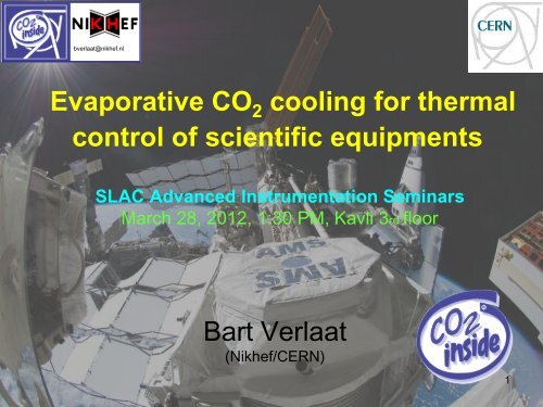
Evaporative CO 2 <strong>cool<strong>in</strong>g</strong> for thermal<br />
control <strong>of</strong> scientific equipments<br />
SLAC Advanced Instrumentation Sem<strong>in</strong>ars<br />
March 28, 2012, 1:30 PM, Kavli 3rd floor<br />
Bart Verlaat<br />
(Nikhef/CERN)<br />
1
verlaat@nikhef.nl<br />
CO 2 Cool<strong>in</strong>g Sem<strong>in</strong>ar<br />
• Introduction to 2phase <strong>cool<strong>in</strong>g</strong> and fluid<br />
trade-<strong>of</strong>f<br />
• CO 2 <strong>cool<strong>in</strong>g</strong> model<strong>in</strong>g<br />
• Introduction to the 2PACL CO 2 circulation<br />
method.<br />
• CO 2 <strong>cool<strong>in</strong>g</strong> <strong>in</strong> the AMS-Experiment.<br />
• CO 2 <strong>cool<strong>in</strong>g</strong> <strong>in</strong> the LHCb Velo Detector<br />
• Ongo<strong>in</strong>g projects.<br />
• Conclusions<br />
2
verlaat@nikhef.nl<br />
Temperature (°C)<br />
Pressure (Bar)<br />
90<br />
60<br />
30<br />
0<br />
-30<br />
What happens <strong>in</strong>side a <strong>cool<strong>in</strong>g</strong> tube?<br />
Heat<strong>in</strong>g a flow from liquid to gas<br />
Liquid<br />
Liquid<br />
Superheat<strong>in</strong>g<br />
Enthalpy (J/kg)<br />
Low ΔT<br />
2-phase<br />
Target flow condition<br />
Isotherm<br />
Sub cooled liquid 2-phase liquid / vapor<br />
Dry-out zone<br />
Gas<br />
Increas<strong>in</strong>g ΔT<br />
(Dry-out)<br />
3<br />
Super heated vapor
verlaat@nikhef.nl<br />
Cool<strong>in</strong>g efficiently scientific<br />
equipment.<br />
• What do we expect <strong>in</strong> general from a 2phase flow<br />
<strong>in</strong> scientific equipment?<br />
– Inside the equipment (Evaporator):<br />
• Small additional <strong>cool<strong>in</strong>g</strong> hardware (small diameter tub<strong>in</strong>g)<br />
• Large heat removal capacity<br />
• Low temperature gradients<br />
– Low gradient from tube wall to fluid<br />
– Low gradient over tube length (Isothermal)<br />
– Outside the equipment (Circulation system)<br />
• Stable temperature<br />
• Control over fluid condition <strong>in</strong> side evaporator<br />
• Which fluid is most suitable?<br />
4
Temperature<br />
bverlaat@nikhef.nl<br />
Temperature pr<strong>of</strong>iles<br />
• To compare different fluids it must be understood which mechanism<br />
contributes to the thermal performance.<br />
ΔT(ΔP)<br />
(Reduced<br />
diameter)<br />
ΔT(ΔP)<br />
Tube length<br />
ΔT(HTC)<br />
(Reduced<br />
diameter)<br />
ΔT(HTC)<br />
ΔT(ΔP+HTC)<br />
(Reduced<br />
diameter)<br />
ΔT(ΔP+HTC)<br />
• For efficient heat transfer: ΔT(ΔP+HTC) as small as possible<br />
• For isothermal heat transfer: ΔT(ΔP) as small as possible<br />
• As <strong>in</strong> general small <strong>cool<strong>in</strong>g</strong> tubes are preferred, so lets <strong>in</strong>troduce a new<br />
property to dist<strong>in</strong>guish the heat transfer relative to the needed volume<br />
Overall Volumetric Heat<br />
Q<br />
V tube*ΔT(ΔP+HTC))<br />
Isothermal Volumetric Heat<br />
Transfer Conduction (W/m3K): Transfer Conduction (W/m 3 K): V tube*ΔT(ΔP))<br />
Q<br />
5
verlaat@nikhef.nl Fluid<br />
• Fluid trade-<strong>of</strong>f regard<strong>in</strong>g<br />
temperature gradients, for<br />
simplicity:<br />
– Pressure drop: Friedel<br />
correlation<br />
– Heat transfer gradients:<br />
Kandlikar correlation.<br />
Temperature<br />
ΔT(ΔP)<br />
(Reduced<br />
diameter)<br />
ΔT(ΔP)<br />
Tube length<br />
Trade-<strong>of</strong>f (1)<br />
CO 2<br />
Heat Transfer<br />
dT(HTC)<br />
(Dashed l<strong>in</strong>es)<br />
ΔT(HTC)<br />
(Reduced<br />
diameter)<br />
Heat transfer gradients (°C)<br />
ΔT(HTC)<br />
10<br />
9<br />
8<br />
7<br />
6<br />
5<br />
4<br />
3<br />
2<br />
1<br />
Heat transfer temperature gradients<br />
L=1 m, Q=100 W, T=-20 °C, VQ=0.5<br />
Total dT(dP+HTC)<br />
(Thick l<strong>in</strong>es)<br />
Pressure drop<br />
dT(dP)<br />
<strong>CO2</strong> (19.7 bar)<br />
Ethane (14.2 bar)<br />
R116 (10.5 bar)<br />
Propane (2.4 bar)<br />
R218 (2 bar)<br />
Ammonia (1.9 bar)<br />
R134a (1.3 bar)<br />
0<br />
0 1 2 3 4 5 6 7 8 9 10<br />
Tube diameter (mm)<br />
ΔT(ΔP+HTC)<br />
(Reduced<br />
diameter)<br />
ΔT(ΔP+HTC)<br />
6
Volumetric heat transfer conduction (W/mm 3 K)<br />
0.035<br />
0.03<br />
0.025<br />
0.02<br />
0.015<br />
0.01<br />
0.005<br />
bverlaat@nikhef.nl<br />
Overall volumetric heat transfer conduction<br />
L=1 m, Q=500 W, T=-20 °C, VQ=0.5<br />
CO 2<br />
Overall<br />
0<br />
0 1 2 3 4 5 6 7 8 9 10<br />
Tube diameter (mm)<br />
Fluid Trade-<strong>of</strong>f (2)<br />
<strong>CO2</strong> (19.7 bar)<br />
Ethane (14.2 bar)<br />
R116 (10.5 bar)<br />
Propane (2.4 bar)<br />
R218 (2 bar)<br />
Ammonia (1.9 bar)<br />
R134a (1.3 bar)<br />
Volumetric heat transfer conduction (W/mm 3 K)<br />
7<br />
6<br />
5<br />
4<br />
3<br />
2<br />
1<br />
Isothermal volumetric heat transfer conduction<br />
L=1 m, Q=500 W, T=-20 °C, VQ=0.5<br />
Isothermal<br />
CO 2<br />
<strong>CO2</strong> (19.7 bar)<br />
Ethane (14.2 bar)<br />
R116 (10.5 bar)<br />
Propane (2.4 bar)<br />
R218 (2 bar)<br />
Ammonia (1.9 bar)<br />
R134a (1.3 bar)<br />
0<br />
0 1 2 3 4 5 6 7 8 9 10<br />
Tube diameter (mm)<br />
• Translat<strong>in</strong>g the temperature gradients to the volumetric heat transfer<br />
conductance<br />
– Clearly visible: CO 2 is a w<strong>in</strong>ner <strong>in</strong> both overall and isothermal.<br />
– Another <strong>in</strong>terest<strong>in</strong>g phenomena: <strong>The</strong> higher the pressure the more<br />
efficient. Is this maybe the simple answer to the perfect fluid?<br />
7
verlaat@nikhef.nl<br />
Is high pressure the answer to<br />
an efficient <strong>cool<strong>in</strong>g</strong> fluid?<br />
• In fact it is, the higher the pressure:<br />
– <strong>The</strong> more the vapor stays compressed<br />
– <strong>The</strong> smaller the needed volume<br />
– But as well: lower gas speeds mean lower pressure<br />
drop.<br />
• Other properties are also important:<br />
– High latent heat (=less flow)<br />
– Low viscosity (=low pressure drop)<br />
– CO 2 is favorable for both properties.<br />
• And on top <strong>of</strong> that pressure drop is less significant<br />
at high pressures as it doesn’t effect the boil<strong>in</strong>g<br />
pressure as it would do at low pressure fluids.<br />
8
verlaat@nikhef.nl<br />
CO 2 a perfect <strong>cool<strong>in</strong>g</strong> fluid<br />
for scientific use<br />
• As shown, CO 2 is a really good candidate <strong>cool<strong>in</strong>g</strong> fluid<br />
if the follow<strong>in</strong>g properties are required (In general for<br />
scientific and high-tech equipment):<br />
– Low mass and low volume <strong>cool<strong>in</strong>g</strong> pipes<br />
– Isothermal behavior<br />
– High heat removal capacity<br />
• <strong>The</strong> stability <strong>in</strong> time is a merit <strong>of</strong> the attached <strong>cool<strong>in</strong>g</strong><br />
plant, here fore the 2PACL pr<strong>in</strong>ciple was <strong>in</strong>vented for<br />
<strong>particle</strong> detector <strong>cool<strong>in</strong>g</strong>.<br />
– However high pressure fluids are less sensitive to<br />
pressure changes, so <strong>in</strong> fact they are as well beneficial for<br />
stable temperature systems.<br />
9
verlaat@nikhef.nl CO<br />
2 heat transfer and<br />
pressure drop model<strong>in</strong>g<br />
• Nowadays good prediction models <strong>of</strong> CO 2 are<br />
available. Especially the models <strong>of</strong> J. Thome from<br />
EPFL Lausanne (Switzerland)<br />
– See SLAC’s Advanced Instrumentation Sem<strong>in</strong>ar talk by<br />
J.Thome @ 9 feb 2011<br />
• Models are flow pattern based and are reasonably well<br />
predict<strong>in</strong>g the flow conditions and the related heat<br />
transfer and pressure drop.<br />
• <strong>The</strong> Thome models are successfully used to predict<br />
the complex thermal behavior <strong>of</strong> <strong>particle</strong> detector<br />
<strong>cool<strong>in</strong>g</strong> circuits.<br />
• A simulation program called CoBra is developed to<br />
analyze full detector <strong>cool<strong>in</strong>g</strong> branches.<br />
10
verlaat@nikhef.nl<br />
Experimental heat transfer<br />
data (measured at SLAC)<br />
Interest<strong>in</strong>g research on<br />
heat transfer is done at<br />
SLAC <strong>in</strong> a jo<strong>in</strong>t effort<br />
with Nikhef.<br />
M. Oriunno (SLAC) &<br />
G. Hemm<strong>in</strong>k (Nikhef)<br />
11
verlaat@nikhef.nl<br />
P x,H x<br />
CoBra Calculator<br />
(<strong>CO2</strong> BRAnch Calculator)<br />
Q x = Q applied + Q environment +Q exchanged<br />
dP x= f(D,Q 1,MF,VQ,P,T) or f(Cv)<br />
dH x= Q tot/MF or pump work<br />
dP pump=∑dP all<br />
dH condenser = ∑dH all<br />
P x+1 = P x - dP x<br />
H x+1 = H x + dH x<br />
T x,VQ xand properties<br />
derived from Refprop<br />
• Iterative method chopp<strong>in</strong>g a long l<strong>in</strong>e <strong>in</strong> small elements (~1mm).<br />
• Model can read simple configuration files giv<strong>in</strong>g simple tube<br />
geometry<br />
• Heat leak and <strong>in</strong>ternal heat exchange between elements can be<br />
taken <strong>in</strong>to account.<br />
• CoBra is a very helpful tool for predict<strong>in</strong>g the complex behavior <strong>of</strong> 2phase<br />
flow.<br />
12<br />
Q x+1<br />
dP x+1<br />
dH x+1<br />
P x+2,H x+2
verlaat@nikhef.nl<br />
CoBra example calculation<br />
2mmID x 5m tube temperature and pressure pr<strong>of</strong>ile. MF=0.3g/s, Tsp=-30ºC, Q=90, x end =0.99<br />
Delta T (`C) & Delta P(Bar)<br />
7<br />
6<br />
5<br />
4<br />
3<br />
2<br />
1<br />
0<br />
Liquid<br />
5mx1.5mmID tube (4m heated), Mass flow=0.3g/s, Q=90Watt , T=-30ºC<br />
Slug<br />
Annular<br />
dT Tube wall (ºC)<br />
dT Fluid (ºC)<br />
dP Fluid (Bar)<br />
Dry-out<br />
1<br />
-1<br />
0<br />
2<br />
0.5 1 1.5 2 2.5 3 3.5 4<br />
3<br />
4.5<br />
4<br />
5<br />
Branch length (m)<br />
0<br />
0 0.1 0.2 0.3 0.4 0.5 0.6 0.7 0.8 0.9 1<br />
• CoBra is able to analyze complex thermal<br />
behavior <strong>of</strong> CO 2 <strong>in</strong> long tubes<br />
350<br />
300<br />
250<br />
200<br />
150<br />
100<br />
50<br />
Bubbly<br />
Slug<br />
Stratified<br />
Annular<br />
Process path<br />
Stratified Wavy<br />
Dry-<br />
out<br />
Mist<br />
13
Delta T (`C) & Delta P(Bar)<br />
bverlaat@nikhef.nl<br />
Internal heat exchange and<br />
IBL temperature and pressure pr<strong>of</strong>ile. MF=0.8g/s, Tsp=-40ºC, Q=101.8, x end =0.5<br />
16<br />
14<br />
12<br />
10<br />
8<br />
6<br />
4<br />
2<br />
Stave TFoM: 13ºC*cm 2 /W<br />
Pixel maximum temperature:<br />
-24.2ºC<br />
Capillary<br />
Boil<strong>in</strong>g starts<br />
0<br />
1 2 3 4 56 78 9 10 11 12<br />
-2<br />
0 5 10 15 20 25<br />
Branch length (m)<br />
ambient heat<strong>in</strong>g<br />
dT Tube wall (ºC)<br />
dT Fluid (ºC)<br />
dP Fluid (Bar)<br />
dT Pixel Chip (ºC)<br />
IBL temperature and pressure pr<strong>of</strong>ile. MF=0.8g/s, Tsp=-40ºC, Q=101.8, x end =0.41<br />
0<br />
1 2 3 4 56 78 9 10 11 12<br />
-2<br />
0 5 10 15 20 25<br />
Figure 7: CoBra calculation example <strong>of</strong> the IBL <strong>cool<strong>in</strong>g</strong> tube. <strong>The</strong> branch has a 1mm <strong>in</strong>let (1-4), a 1.5 mm <strong>cool<strong>in</strong>g</strong> tube (4-<br />
8), a 2mm outlet (8-9) followed by a 3mm outlet (9-12). <strong>The</strong> dashed temperature pr<strong>of</strong>ile is the actual sensor temperature<br />
tak<strong>in</strong>g <strong>in</strong>to account the conductance <strong>of</strong> the support structure. <strong>The</strong> graph on the left has no <strong>in</strong>ternal heat exchange, the<br />
right graph takes <strong>in</strong>ternal heat exchange <strong>of</strong> the <strong>in</strong> and outlet tube <strong>in</strong>to account.<br />
Delta T (`C) & Delta P(Bar)<br />
16<br />
14<br />
12<br />
10<br />
8<br />
6<br />
4<br />
2<br />
Stave TFoM: 13ºC*cm 2 /W<br />
Pixel maximum temperature:<br />
-24.4ºC<br />
No Boil<strong>in</strong>g<br />
Branch length (m)<br />
Boil<strong>in</strong>g starts<br />
Figures from: DESIGN CONSIDERATIONS OF LONG LENGTH EVAPORATIVE <strong>CO2</strong> COOLING LINES<br />
Bart Verlaat and Joao Noite, GL-209, 10th IIF/IIR Gustav Lorentzen Conference on Natural Work<strong>in</strong>g Fluids, Delft, <strong>The</strong> Netherlands 2012<br />
dT Tube wall (ºC)<br />
dT Fluid (ºC)<br />
dP Fluid (Bar)<br />
dT Pixel Chip (ºC)<br />
14
verlaat@nikhef.nl<br />
Comparison to test results<br />
m = 1.48g/s | Q total = 256.87W | P <strong>in</strong> = 26.40Bar | T <strong>in</strong> = -17.40°C | dP = 6.33Bar | dT = 10.86°C<br />
Temperature [°C]<br />
-6<br />
-8<br />
-10<br />
-12<br />
-14<br />
-16<br />
-18<br />
Electronics (1.8mm)<br />
CMS-B-PIX<br />
Inlet tube (1.8mm)<br />
CMS detector<br />
(1.4mm)<br />
Exp. Wall Temperature<br />
<strong>The</strong>ory Wall Temperature<br />
<strong>The</strong>ory CO 2 Temperature<br />
<strong>The</strong>ory CO 2 Pressure<br />
-20<br />
0 5 10 15<br />
Loop Length [m]<br />
20<br />
Outlet tube (1.8mm)<br />
27<br />
26<br />
25<br />
24<br />
23<br />
22<br />
21<br />
IBL temperature and pressure pr<strong>of</strong>ile. MF=1.1g/s, Tsp=-26.71ºC, Q=73.5, x end =0.36<br />
12<br />
-1<br />
0 5<br />
3 4<br />
10<br />
56 78 9<br />
15<br />
10<br />
20<br />
1112<br />
25<br />
Branch length (m)<br />
Figure 8: Temperature and pressure test results <strong>of</strong> the CMS pixel upgrade <strong>cool<strong>in</strong>g</strong> branch (left) and the Atlas IBL<br />
<strong>cool<strong>in</strong>g</strong> branch (right). Comparison with the CoBra calculator showed that the calculator is a promis<strong>in</strong>g tool for<br />
predict<strong>in</strong>g the temperature and pressure gradients over long length <strong>cool<strong>in</strong>g</strong> branches.<br />
Pressure [Bar]<br />
Delta T (`C) & Delta P(Bar)<br />
9<br />
8<br />
7<br />
6<br />
5<br />
4<br />
3<br />
2<br />
1<br />
0<br />
Inlet tube<br />
(1mm)<br />
Atlas-IBL<br />
Detector<br />
(1.5mm)<br />
Outlet tube (2mm)<br />
dT Tube wall (ºC)<br />
dT Fluid (ºC)<br />
dP Fluid (Bar)<br />
Outlet tube<br />
(3mm)<br />
Figures from: DESIGN CONSIDERATIONS OF LONG LENGTH EVAPORATIVE <strong>CO2</strong> COOLING LINES<br />
Bart Verlaat and Joao Noite, GL-209, 10th IIF/IIR Gustav Lorentzen Conference on Natural Work<strong>in</strong>g Fluids, Delft, <strong>The</strong> Netherlands 2012<br />
15
Temperature (°C)<br />
Pressure (Bar)<br />
Pressure<br />
90<br />
60<br />
30<br />
0<br />
-30<br />
bverlaat@nikhef.nl What<br />
Liquid Vapor<br />
2-phase<br />
Enthalpy<br />
What happens <strong>in</strong>side a <strong>cool<strong>in</strong>g</strong> tube?<br />
Heat<strong>in</strong>g a flow from liquid to gas<br />
Liquid<br />
Liquid<br />
Superheat<strong>in</strong>g<br />
Enthalpy (J/kg)<br />
Low ΔT<br />
2-phase<br />
Target flow condition<br />
Sub cooled liquid 2-phase liquid / vapor<br />
circulation method can we use?<br />
Isotherm<br />
Dry-out zone<br />
Gas<br />
Increas<strong>in</strong>g ΔT<br />
(Dry-out)<br />
3<br />
Super heated vapor<br />
Refrigeration method:<br />
(Atlas)<br />
Compressor<br />
Cool<strong>in</strong>g plant<br />
BP. Regulator<br />
Vapor compression system<br />
Warm transfer<br />
Heater<br />
Detector<br />
If we remember slide 3, we see that proper<br />
<strong>cool<strong>in</strong>g</strong> takes place on the liquid side, while<br />
compressors need gas as <strong>in</strong>put. It is better to<br />
<strong>in</strong>vent a cycle stay<strong>in</strong>g on the liquid side.<br />
=> externally cooled pump cycle.
Pressure<br />
bverlaat@nikhef.nl New cycle for <strong>particle</strong> detectors: 2PACL<br />
(<strong>The</strong> 2-Phase Accumulator Controlled Loop )<br />
Liquid Vapor<br />
2-phase<br />
Enthalpy<br />
2PACL method:<br />
(LHCb)<br />
Compressor<br />
Chiller Liquid circulation<br />
Pumped liquid system,<br />
cooled externally<br />
Cold transfer<br />
• <strong>The</strong> 2PACL has the follow<strong>in</strong>g advantages:<br />
– Cycle stays on the liquid side, no heat required (experiment can be cooled unpowered<br />
and no control heaters required)<br />
– Evaporator pressure=(temperature) controlled with a 2-phase vessel away from the<br />
experiment. No local control nor sens<strong>in</strong>g needed!<br />
– All control hardware <strong>in</strong> a distant accessible <strong>cool<strong>in</strong>g</strong> plant<br />
– Primary <strong>cool<strong>in</strong>g</strong> can be anyth<strong>in</strong>g, no accurate temperature control needed as long as it<br />
is colder than the 2PACL 2-phase temperature.<br />
– Inlet fluid state def<strong>in</strong>ed by <strong>physics</strong> => saturated liquid.<br />
– Large temperature range (typical from room temperature down to -40°C)<br />
17<br />
Pump<br />
Cool<strong>in</strong>g plant Detector
verlaat@nikhef.nl<br />
Cool<strong>in</strong>g plant (controls &<br />
actuators) <strong>in</strong> a safe and<br />
accessible area<br />
HFC Chiller<br />
P 7<br />
1<br />
Condenser<br />
2PACL application <strong>in</strong> a<br />
2-Phase<br />
Accumulator<br />
Heat <strong>in</strong><br />
Pump<br />
<strong>particle</strong> detector<br />
Shield<strong>in</strong>g wall<br />
Long distance<br />
(50-100m)<br />
6<br />
2 3<br />
Transfer l<strong>in</strong>e<br />
(Heat exchanger)<br />
5<br />
Only passive pip<strong>in</strong>g <strong>in</strong><br />
detector area. Manifolds<br />
<strong>in</strong> accessible locations.<br />
Capillaries (3-4)<br />
for flow distribution<br />
Evaporator <strong>in</strong>side<br />
detector (4-5)<br />
4<br />
P 4-5<br />
18
verlaat@nikhef.nl<br />
Pressure control<br />
with accumulator.<br />
Change set-po<strong>in</strong>t.<br />
1<br />
7<br />
2-Phase Accumulator Controlled Loop<br />
(2PACL)<br />
7<br />
Pump<br />
Pressure<br />
6<br />
2<br />
1<br />
Liquid<br />
2<br />
6<br />
3<br />
4&5<br />
2-phase<br />
(Evaporation)<br />
Red dot (detector)<br />
on saturation l<strong>in</strong>e.<br />
Isothermal l<strong>in</strong>e<br />
3<br />
5<br />
4<br />
Gas<br />
Enthalpy<br />
19
verlaat@nikhef.nl<br />
Lower<strong>in</strong>g saturation<br />
pressure<br />
7<br />
Cool<strong>in</strong>g 7<br />
1<br />
2-Phase Accumulator Controlled Loop<br />
(2PACL)<br />
Pump<br />
Pressure<br />
6<br />
2<br />
1<br />
Liquid<br />
2<br />
6<br />
3<br />
4&5<br />
2-phase<br />
(Evaporation)<br />
Isothermal l<strong>in</strong>e<br />
3<br />
5<br />
4<br />
Gas<br />
Red dot (detector)<br />
follows saturation l<strong>in</strong>e.<br />
Enthalpy<br />
20
verlaat@nikhef.nl<br />
Lower<strong>in</strong>g saturation<br />
pressure<br />
7<br />
Cool<strong>in</strong>g 7<br />
1<br />
2-Phase Accumulator Controlled Loop<br />
(2PACL)<br />
Pump<br />
Pressure<br />
6<br />
2<br />
1<br />
Liquid<br />
2<br />
6<br />
3<br />
4&5<br />
2-phase<br />
(Evaporation)<br />
Isothermal l<strong>in</strong>e<br />
3<br />
5<br />
4<br />
Gas<br />
Red dot (detector)<br />
follows saturation l<strong>in</strong>e.<br />
Enthalpy<br />
21
verlaat@nikhef.nl<br />
Lower<strong>in</strong>g saturation<br />
pressure<br />
7<br />
Cool<strong>in</strong>g 7<br />
1<br />
2-Phase Accumulator Controlled Loop<br />
(2PACL)<br />
Pump<br />
Pressure<br />
6<br />
2<br />
1<br />
Liquid<br />
2<br />
6<br />
3<br />
4&5<br />
2-phase<br />
(Evaporation)<br />
Isothermal l<strong>in</strong>e<br />
3<br />
5<br />
4<br />
Gas<br />
Red dot (detector)<br />
follows saturation l<strong>in</strong>e.<br />
Enthalpy<br />
22
verlaat@nikhef.nl<br />
Set po<strong>in</strong>t reached<br />
1<br />
7<br />
2-Phase Accumulator Controlled Loop<br />
(2PACL)<br />
7<br />
Pump<br />
Pressure<br />
6<br />
2<br />
1<br />
Liquid<br />
2<br />
6<br />
3<br />
4&5<br />
2-phase<br />
(Evaporation)<br />
Isothermal l<strong>in</strong>e<br />
3<br />
5<br />
4<br />
Gas<br />
Enthalpy<br />
23
verlaat@nikhef.nl<br />
Increas<strong>in</strong>g saturation<br />
pressure<br />
7<br />
Heat<strong>in</strong>g<br />
1<br />
7<br />
2-Phase Accumulator Controlled Loop<br />
(2PACL)<br />
Pump<br />
Pressure<br />
6<br />
2<br />
1<br />
Liquid<br />
2<br />
6<br />
3<br />
4&5<br />
2-phase<br />
(Evaporation)<br />
Isothermal l<strong>in</strong>e<br />
3<br />
5<br />
4<br />
Gas<br />
Red dot (detector)<br />
follows saturation l<strong>in</strong>e.<br />
Enthalpy<br />
24
verlaat@nikhef.nl<br />
Increas<strong>in</strong>g saturation<br />
pressure 7<br />
Heat<strong>in</strong>g 7<br />
1<br />
2-Phase Accumulator Controlled Loop<br />
(2PACL)<br />
Pump<br />
Pressure<br />
6<br />
2<br />
1<br />
Liquid<br />
2<br />
6<br />
3<br />
4&5<br />
2-phase<br />
(Evaporation)<br />
Isothermal l<strong>in</strong>e<br />
3<br />
5<br />
4<br />
Gas<br />
Red dot (detector)<br />
follows saturation l<strong>in</strong>e.<br />
Enthalpy<br />
25
verlaat@nikhef.nl<br />
Increas<strong>in</strong>g saturation<br />
pressure<br />
7<br />
Heat<strong>in</strong>g 7<br />
1<br />
2-Phase Accumulator Controlled Loop<br />
(2PACL)<br />
Pump<br />
Pressure<br />
6<br />
2<br />
1<br />
Liquid<br />
2<br />
6<br />
3<br />
4&5<br />
2-phase<br />
(Evaporation)<br />
Isothermal l<strong>in</strong>e<br />
3<br />
5<br />
4<br />
Gas<br />
Red dot (detector)<br />
follows saturation l<strong>in</strong>e.<br />
Enthalpy<br />
26
verlaat@nikhef.nl<br />
Set po<strong>in</strong>t reached<br />
1<br />
7<br />
2-Phase Accumulator Controlled Loop<br />
(2PACL)<br />
7<br />
Pump<br />
Pressure<br />
6<br />
2<br />
1<br />
Liquid<br />
2<br />
6<br />
3<br />
4&5<br />
2-phase<br />
(Evaporation)<br />
Isothermal l<strong>in</strong>e<br />
3<br />
5<br />
4<br />
Gas<br />
Enthalpy<br />
27
verlaat@nikhef.nl<br />
Switch<strong>in</strong>g on detector<br />
1<br />
7<br />
2-Phase Accumulator Controlled Loop<br />
(2PACL)<br />
7<br />
Pump<br />
Pressure<br />
6<br />
2<br />
1<br />
Liquid<br />
2<br />
6<br />
3<br />
4&5<br />
2-phase<br />
(Evaporation)<br />
Red dot (detector)<br />
evaporation starts.<br />
Isothermal l<strong>in</strong>e<br />
3<br />
5<br />
4<br />
Gas<br />
Enthalpy<br />
Heat<br />
28
verlaat@nikhef.nl<br />
Power<strong>in</strong>g detector<br />
Cool<strong>in</strong>g 7<br />
1<br />
2-Phase Accumulator Controlled Loop<br />
(2PACL)<br />
7<br />
Pump<br />
Pressure<br />
6<br />
2<br />
1<br />
Liquid<br />
2<br />
6<br />
3<br />
4 5<br />
2-phase<br />
(Evaporation)<br />
Isothermal l<strong>in</strong>e<br />
3<br />
5<br />
4<br />
Gas<br />
Red l<strong>in</strong>e (detector)<br />
<strong>in</strong> evaporation.<br />
Enthalpy<br />
Heat<br />
29
verlaat@nikhef.nl<br />
Power<strong>in</strong>g detector<br />
Cool<strong>in</strong>g 7<br />
1<br />
2-Phase Accumulator Controlled Loop<br />
(2PACL)<br />
7<br />
Pump<br />
Pressure<br />
6<br />
2<br />
1<br />
Liquid<br />
2<br />
3<br />
2-phase<br />
(Evaporation)<br />
4 5<br />
6<br />
Isothermal l<strong>in</strong>e<br />
3<br />
5<br />
4<br />
Gas<br />
Red l<strong>in</strong>e (detector)<br />
<strong>in</strong> evaporation.<br />
Enthalpy<br />
Heat<br />
30
verlaat@nikhef.nl<br />
Detector is on<br />
1<br />
7<br />
2-Phase Accumulator Controlled Loop<br />
(2PACL)<br />
7<br />
Pump<br />
Pressure<br />
6<br />
2<br />
1<br />
Liquid<br />
2<br />
3<br />
2-phase<br />
(Evaporation)<br />
4 5<br />
6<br />
Isothermal l<strong>in</strong>e<br />
3<br />
5<br />
4<br />
Gas<br />
Red l<strong>in</strong>e (detector)<br />
<strong>in</strong> evaporation.<br />
Enthalpy<br />
Heat<br />
31
verlaat@nikhef.nl<br />
Unpower<strong>in</strong>g detector<br />
Heat<strong>in</strong>g 7<br />
1<br />
2-Phase Accumulator Controlled Loop<br />
(2PACL)<br />
7<br />
Pump<br />
Pressure<br />
6<br />
2<br />
1<br />
Liquid<br />
2<br />
6<br />
3<br />
4 5<br />
2-phase<br />
(Evaporation)<br />
Isothermal l<strong>in</strong>e<br />
3<br />
5<br />
4<br />
Gas<br />
Red l<strong>in</strong>e (detector)<br />
Evaporates.<br />
Enthalpy<br />
32
verlaat@nikhef.nl<br />
Detector power is <strong>of</strong>f<br />
1<br />
7<br />
2-Phase Accumulator Controlled Loop<br />
(2PACL)<br />
7<br />
Pump<br />
Pressure<br />
6<br />
2<br />
1<br />
Liquid<br />
2<br />
6<br />
3<br />
4&5<br />
2-phase<br />
(Evaporation)<br />
Isothermal l<strong>in</strong>e<br />
3<br />
5<br />
4<br />
Gas<br />
Enthalpy<br />
33
verlaat@nikhef.nl<br />
CO 2 <strong>cool<strong>in</strong>g</strong> projects <strong>in</strong><br />
<strong>particle</strong> <strong>physics</strong><br />
• 2 CO 2 <strong>cool<strong>in</strong>g</strong> systems have successfully been built for<br />
<strong>particle</strong> detectors<br />
– AMS-Tracker experiment on the International Space Station<br />
– LHCb-Velo experiment for the Large Hadron Collider at CERN<br />
• Many <strong>future</strong> CO 2 <strong>cool<strong>in</strong>g</strong> systems are under design:<br />
– Atlas Inner B-layer @ CERN<br />
– CMS upgrade pixel @ CERN<br />
– Belle-2 @ KEKb (Japan)<br />
• Some are foreseen for the far <strong>future</strong>:<br />
– CMS upgrade tracker @ CERN<br />
– Atlas upgrade pixel and tracker @ CERN<br />
– LC-TPC for the <strong>future</strong> L<strong>in</strong>ear Collider<br />
34
verlaat@nikhef.nl<br />
<strong>The</strong> 1 st CO 2 <strong>cool<strong>in</strong>g</strong> system <strong>in</strong> Space!<br />
A CO 2 <strong>cool<strong>in</strong>g</strong> system for Alpha Magnetic Spectrometer (AMS)<br />
Tracker Detector on the International Space station (ISS)<br />
CO 2 <strong>cool<strong>in</strong>g</strong><br />
radiator<br />
AMS <strong>in</strong> the Shuttle<br />
(STS-134, May 2011)<br />
AMS on the ISS<br />
35
verlaat@nikhef.nl<br />
MAGNETE<br />
AMS-Tracker <strong>The</strong>rmal Control System<br />
(AMS-TTCS)<br />
144 WATT<br />
TRD<br />
TOF<br />
TRACKER<br />
TOF<br />
RICH<br />
ECAL<br />
RADIATORE<br />
150 Watt detector with<br />
evaporator r<strong>in</strong>gs<br />
condensatori<br />
Primary <strong>cool<strong>in</strong>g</strong> not<br />
needed <strong>in</strong> space as<br />
environment is cold.<br />
Direct radiation to space<br />
Cool<strong>in</strong>g system<br />
component boxes<br />
(1 redundant)<br />
36
verlaat@nikhef.nl<br />
Tracker connections<br />
Inner plane silicon<br />
ladders<br />
AMS-Tracker with<br />
CO 2 <strong>cool<strong>in</strong>g</strong> r<strong>in</strong>gs.<br />
Inner plane thermal<br />
bars and hybrids<br />
Inner plane<br />
evaporator r<strong>in</strong>gs<br />
37
verlaat@nikhef.nl<br />
Temperature (°C)<br />
10<br />
5<br />
0<br />
-5<br />
-10<br />
-15<br />
-20<br />
-25<br />
AMS TTCS Cool<strong>in</strong>g<br />
performance <strong>in</strong> space (1)<br />
Evaporator partly s<strong>in</strong>gle<br />
phase (gradients)<br />
Heat<br />
exchanger<br />
heat<strong>in</strong>g<br />
1 orbit (~1.5hour)<br />
Accumulator<br />
set po<strong>in</strong>t<br />
change<br />
Evaporator<br />
fully 2-phase<br />
13:00 15:00 17:00 19:00 21:00 23:00 01:00<br />
Pump <strong>in</strong>let (PT02_P)<br />
Accumulator (PT01_P)<br />
Evaporator <strong>in</strong>let (DS13-P)<br />
Evap 1 (SensE)<br />
Evap 2 (SensG)<br />
Evap 3 (SensF)<br />
Vary<strong>in</strong>g CO 2 liquid<br />
due to orbital<br />
fluctuations<br />
Time(HH:MM)<br />
38
verlaat@nikhef.nl<br />
Temperature (°C)<br />
20<br />
15<br />
10<br />
5<br />
0<br />
-5<br />
-10<br />
-15<br />
-20<br />
-25<br />
-30<br />
08/06/11<br />
Soyuz<br />
dock<strong>in</strong>g<br />
AMS TTCS Cool<strong>in</strong>g<br />
performance <strong>in</strong> space (2)<br />
10/06/11<br />
12/06/11<br />
14/06/11<br />
Detector<br />
switched-<strong>of</strong>f<br />
Solar Panel<br />
orientation<br />
change<br />
16/06/11<br />
18/06/11<br />
20/06/11<br />
Pump <strong>in</strong>let (PT02_P)<br />
Accumulator (PT01_P)<br />
Evaporator <strong>in</strong>let (DS13-P)<br />
Evap 1 (SensE)<br />
Evap 2 (SensG)<br />
Evap 3 (SensF)<br />
Magnet Average<br />
Date (DD/MM/YY)<br />
39
verlaat@nikhef.nl<br />
AMS TTCS Cool<strong>in</strong>g<br />
performance <strong>in</strong> space (3)<br />
6 month stable at 0⁰C despite cold low beta periods<br />
40
verlaat@nikhef.nl<br />
VELO detector: 1.5 kW@-30°C<br />
(Runn<strong>in</strong>g successfully s<strong>in</strong>ce 2007)<br />
CO 2 <strong>cool<strong>in</strong>g</strong> projects <strong>in</strong> LHC<br />
27 km<br />
CMS pixel: 15 kW@-20°C<br />
(Operational 2014)<br />
LHC<br />
Atlas IBL: 1.5 kW@-40°C<br />
(Operational 2013)<br />
Ca. 100m<br />
41
verlaat@nikhef.nl<br />
LHCb-Velo <strong>The</strong>rmal Control System<br />
(LHCb-VTCS)<br />
Transfer tube<br />
Concentric assembly<br />
Evaporator<br />
Passive tub<strong>in</strong>g only Cool<strong>in</strong>g Plant<br />
All active hardware<br />
Cool<strong>in</strong>g capacity: 1.5 kW@-30°C<br />
42
verlaat@nikhef.nl VTCS<br />
Evaporator<br />
43
gas<br />
2-phase<br />
R507a<br />
chiller<br />
gas<br />
2-phase<br />
bverlaat@nikhef.nl<br />
Start–up <strong>of</strong> the VTCS dur<strong>in</strong>g October<br />
80<br />
2009 commission<strong>in</strong>g:<br />
8:40 - Start-up with set-po<strong>in</strong>t -5°C<br />
11:10 - Detector switched on<br />
60<br />
12:50 – Set po<strong>in</strong>t to -15°C<br />
15:30 - Set po<strong>in</strong>t to -25°C<br />
50<br />
17:10 - Set po<strong>in</strong>t to -30°C<br />
18:20 - Set po<strong>in</strong>t to -35°C (System Limit)<br />
19:10 - Set po<strong>in</strong>t to -34°C 40<br />
19:30 - Set po<strong>in</strong>t to -25°C<br />
20:00 - Detector Switched <strong>of</strong>f<br />
Condenser<br />
10<br />
Accumulator<br />
Transfer l<strong>in</strong>es<br />
Cool<strong>in</strong>g plant area (Ca. 10 50m) VELO area<br />
9<br />
Pump<br />
1 2<br />
8<br />
Accumulator Set-po<strong>in</strong>t temperature Silicon temperature (°C) (°C) Pump liquid Accumulator temperature Set-po<strong>in</strong>t (°C) temperature Evaporator (°C) saturation Pump liquid temperature (°C)<br />
Temperature(°C), Level(%)<br />
70<br />
30<br />
20<br />
0<br />
-10<br />
-20<br />
Concentric tube<br />
7<br />
3<br />
Restriction<br />
VTCS Commission<strong>in</strong>g results:<br />
Start-up and operation<br />
ator Set-po<strong>in</strong>t temperature (°C) Pump liquid temperature (°C) Evaporator saturation temperature (°C) Accumulator liquid level (%) Detector heat load (W)<br />
Temperature(°C), Level(%)<br />
4<br />
80<br />
70<br />
60<br />
50<br />
40<br />
30<br />
20<br />
10<br />
0<br />
-10<br />
-20<br />
-30<br />
-40<br />
-50<br />
-60<br />
09:00 12:00 15:00 18:00 21:00<br />
01-Oct-2009<br />
-25<br />
Time (hh:mm)<br />
5<br />
Silicon temperature (°C) Accumulator Set-po<strong>in</strong>t temperature (°C) Pump liquid temperature (°C) Evaporator saturation temperature (°C) Accumulator liquid<br />
Evaporator / Modules<br />
6<br />
10-Accu liquid level<br />
10-Accumulator set-po<strong>in</strong>t<br />
A<br />
Temperature(°C), Level(%)<br />
-26.4286<br />
-27.8571<br />
-29.2857<br />
-30.7143<br />
-32.1429<br />
-33.5714<br />
-35<br />
-36.4286<br />
-37.8571<br />
-39.2857<br />
-40.7143<br />
-42.1429<br />
Detector power<br />
A-Silicon temperature<br />
9-Pumped liquid<br />
-30°C SP<br />
-35°C SP<br />
800<br />
700<br />
600<br />
500<br />
400<br />
300<br />
200<br />
100<br />
0<br />
-34°C SP<br />
44<br />
Heatload (W)
Pressure (Bar)<br />
SP=21°C<br />
(Start-up)<br />
SP=-5°C<br />
bverlaat@nikhef.nl<br />
Freez<strong>in</strong>g<br />
(Solid/Liquid)<br />
SP=-15°C<br />
SP=-25°C<br />
SP=-30°C<br />
SP=-35°C<br />
VTCS Commission<strong>in</strong>g results:<br />
Start-up and operation <strong>in</strong> the PH-diagram<br />
T=-40°C<br />
9-Pump <strong>in</strong>let<br />
Liquid<br />
Enthalpy (kJ/kg)<br />
2-Phase<br />
(Liquid/Vapor)<br />
T=-40°C<br />
T=20°C<br />
T=0°C<br />
T=-20°C<br />
Start-up sequence<br />
1. Increase pressure to<br />
make liquid.<br />
2. Pump at high pressure<br />
and cool down <strong>in</strong> liquid<br />
mode<br />
3. Lower pressure to<br />
desired set-po<strong>in</strong>t<br />
4. Power-up detector<br />
Switch-<strong>of</strong>f detector<br />
Lowest possible set-po<strong>in</strong>t<br />
(liquid approaches<br />
saturation l<strong>in</strong>e)<br />
45
verlaat@nikhef.nl<br />
IBL detector:<br />
• Ø80mm x 800mm<br />
• 1.5 kW @ -40°C<br />
• 14 staves with 1 <strong>cool<strong>in</strong>g</strong> pipe<br />
New detector with smaller beam<br />
pipe <strong>in</strong> space <strong>of</strong> current beam pipe<br />
Atlas IBL-<strong>cool<strong>in</strong>g</strong> system (1)<br />
Carbon foam structure<br />
1.5mm ID titanium <strong>cool<strong>in</strong>g</strong> pipe<br />
Pixel detector<br />
chips<br />
(70watt/stave)<br />
46
verlaat@nikhef.nl<br />
CMS upgrade pixel <strong>cool<strong>in</strong>g</strong><br />
system<br />
• Replacement and<br />
upgrade <strong>of</strong> current<br />
pixel detector<br />
• 15kW @ -20ºC<br />
• Very long serial l<strong>in</strong>es<br />
with relative high heat<br />
flux<br />
F-PIX<br />
(Forward)<br />
47
verlaat@nikhef.nl<br />
KEK Belle-2 SVD and PXD<br />
Belle-2 PXD and SVD, 1.5 kW@-30ºC<br />
Common CO 2 <strong>cool<strong>in</strong>g</strong> plant<br />
development with Atlas IBL<br />
Belle-II SVD<br />
detector<br />
Belle-II pixel detector<br />
(Rapid Prototyp<strong>in</strong>g heat s<strong>in</strong>k)<br />
48
verlaat@nikhef.nl CO<br />
2 <strong>cool<strong>in</strong>g</strong> support<br />
Traci Cora Marco<br />
• To support the CO 2 <strong>cool<strong>in</strong>g</strong> projects <strong>in</strong> <strong>particle</strong> <strong>physics</strong> several test systems are under<br />
development:<br />
• Cora (CO 2 Research Apparatus)<br />
– Fixed test plant for CERN based research (0-2kW, +20 to -35ºC)<br />
• Marco (Multipurpose Apparatus for Research on CO 2<br />
– Fully automatic (User friendly) CO 2 test system for general use (0-2kW, +20 to -45ºC)<br />
– Base design for <strong>future</strong> on detector <strong>cool<strong>in</strong>g</strong> plants (Atlas IBL, Belle-2)<br />
• Traci (Transportable Refrigeration Apparatus for CO 2 Investigation)<br />
– Small test system for laboratory use<br />
– New simplified 2PACL concept to reduce cost and complexity (0-350W, +20 to -40ºC)<br />
49
Experiment<br />
connection<br />
4<br />
5<br />
Experiment<br />
vent<strong>in</strong>g<br />
bverlaat@nikhef.nl TRACI<br />
Local experiment box<br />
condenser<br />
Flow regulation<br />
compressor<br />
Transportable Refrigeration Apparatus for Co 2 Investigation<br />
Concentric hose<br />
P T<br />
5<br />
Heater<br />
TEV<br />
R404a Chiller<br />
T<br />
6<br />
R404a evaporator/<br />
CO 2 condenser<br />
T<br />
1<br />
TRACI layout<br />
CO 2 pump<br />
P,T<br />
3<br />
P 10<br />
T<br />
CO 2 loop<br />
Accumulator<br />
-50<br />
9:00 10:30 12:00 13:30 15:00 16:30<br />
Time (hh:mm)<br />
• TRACI: A simplified new concept for provid<strong>in</strong>g a conditioned CO 2 flow for<br />
<strong>cool<strong>in</strong>g</strong> research.<br />
• 2PACL pr<strong>in</strong>ciple simplified (few functions have been <strong>in</strong>tegrated)<br />
– Integrated 2PACL (I-2PACL )<br />
– Patent <strong>of</strong> I-2PACL concept filed<br />
• Goal: An easy to (mass) produce user friendly system<br />
– Operational from +25⁰C to -40 ⁰C<br />
– Initial <strong>cool<strong>in</strong>g</strong> power up to 350 Watt (depend<strong>in</strong>g on m<strong>in</strong>imum temperature)<br />
Temperature (°C)<br />
30<br />
20<br />
10<br />
0<br />
-10<br />
-20<br />
-30<br />
-40<br />
<strong>CO2</strong> Chart liquid temperature Title (at pump)<br />
<strong>CO2</strong> temperature<br />
Accumulator saturation temperature<br />
150 W on Power <strong>of</strong>f<br />
150 W on<br />
50
verlaat@nikhef.nl<br />
<strong>The</strong> TRACI factory<br />
• Prototypes are already “mass produced”<br />
– 2 have been build (Atlas & LHCb)<br />
– 3 under construction (Atlas, CMS & Nikhef/AIDA for<br />
development)<br />
– Investigat<strong>in</strong>g a start-up company for real production<br />
51
verlaat@nikhef.nl<br />
Commercial chiller<br />
TRACI a modular design<br />
CO 2 pip<strong>in</strong>g <strong>in</strong> a 2Dfoambox<br />
User <strong>in</strong>terface:<br />
• On/<strong>of</strong>f and reset buttons<br />
• Error <strong>in</strong>dication<br />
• Pressure controller<br />
Control: Simple<br />
conditioner and relay<br />
logic<br />
52
verlaat@nikhef.nl MARCO<br />
Multipurpose Apparatus for Research on CO 2<br />
• MARCO is prototype CO 2 2PACL<br />
system for multipurpose use.<br />
• User friendly<br />
– Automatic experiment connection<br />
– Automatic fill<strong>in</strong>g<br />
• Designed accord<strong>in</strong>g to CERN<br />
experiment standards.<br />
– Basel<strong>in</strong>e concept for the detectors IBL<br />
(CERN) and Belle-2 (KEK), common<br />
development with MPI-Munich.<br />
– PVSS-Unicos control <strong>in</strong>terface<br />
• Low temperature design<br />
– 2kW@-45ºC<br />
– Frequency controlled 2-stage chiller<br />
53
verlaat@nikhef.nl MARCO<br />
A CO 2 2PACL build <strong>in</strong> MPI<br />
production<br />
Controls build<br />
at CERN-DT<br />
2-stage chiller for IBL<br />
temperatures from<br />
ECR-Nederland<br />
54
verlaat@nikhef.nl<br />
Conclusions<br />
• CO 2 is a very good candidate fluid for applications were limited <strong>cool<strong>in</strong>g</strong><br />
space is available or limited additional mass is allowed.<br />
• CO 2 <strong>cool<strong>in</strong>g</strong> is a good candidate if high power densities are present and an<br />
isothermal heat s<strong>in</strong>k is required<br />
• CO 2 <strong>cool<strong>in</strong>g</strong> is widely accepted <strong>in</strong> Particle Physics community as the <strong>future</strong><br />
<strong>cool<strong>in</strong>g</strong> method for the <strong>in</strong>ner silicon detectors.<br />
• <strong>The</strong> 2PACL concept has proven to be a good method for controll<strong>in</strong>g<br />
evaporation conditions <strong>in</strong> distant set-ups<br />
• 2 CO 2 systems are operational <strong>in</strong> <strong>particle</strong> <strong>physics</strong> and perform well.<br />
• Several new systems are under development <strong>in</strong>clud<strong>in</strong>g systems for test<strong>in</strong>g<br />
55
verlaat@nikhef.nl<br />
It’s cold here, can you<br />
turn the <strong>cool<strong>in</strong>g</strong> <strong>of</strong>f?<br />
Questions?<br />
56