Rapid Die Face Design: a step towards End-to-End ... - ESI Group
Rapid Die Face Design: a step towards End-to-End ... - ESI Group
Rapid Die Face Design: a step towards End-to-End ... - ESI Group
Create successful ePaper yourself
Turn your PDF publications into a flip-book with our unique Google optimized e-Paper software.
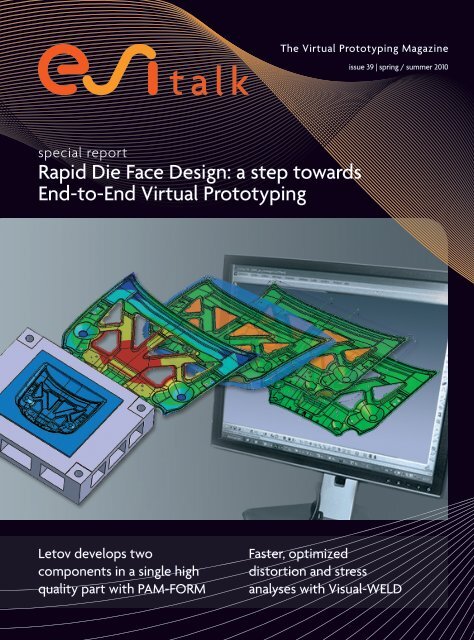
special report<br />
<strong>Rapid</strong> <strong>Die</strong> <strong>Face</strong> <strong>Design</strong>: a <strong>step</strong> <strong><strong>to</strong>wards</strong><br />
<strong>End</strong>-<strong>to</strong>-<strong>End</strong> Virtual Pro<strong>to</strong>typing<br />
Le<strong>to</strong>v develops two<br />
components in a single high<br />
quality part with PAM-FORM<br />
The Virtual Pro<strong>to</strong>typing Magazine<br />
issue 39 | spring / summer 2010<br />
Faster, optimized<br />
dis<strong>to</strong>rtion and stress<br />
analyses with Visual-WELD
contents<br />
esi talk is issued bi-annually by <strong>ESI</strong> <strong>Group</strong><br />
Executive Edi<strong>to</strong>r: Amy de Rouvray<br />
Edi<strong>to</strong>r-in-Chief: Elise Lavoue - elise.lavoue@esi-group.com<br />
<strong>ESI</strong> <strong>Group</strong> Marketing<br />
PARC D’AFFAIRES SILIC<br />
99 RUE DES SOLETS - BP 80112<br />
94513 Rungis Cedex - FRANCE<br />
Tel: +33 (0) 1 41 73 58 00 - Fax: +33 (0) 1 46 87 72 02<br />
www.esi-group.com - info@esi-group.com<br />
<strong>Design</strong>: Agence TETRAKTYS<br />
ISSN 1635 – 866X<br />
Print: RIVET PRESSE EDITION<br />
24, rue Claude-Henri-Gorceix - 87022 Limoges<br />
Dépôt légal: Mai 2010<br />
All PAM- and SYS- product names as well as other products belonging <strong>to</strong> <strong>ESI</strong>’s portfolio are tradenames or trademarks of <strong>ESI</strong><br />
<strong>Group</strong>, except specified proprietary mention. All other trademarks are the property of their respective owners.<br />
All text and images included in the articles are the copyright of the companies presenting their applications and simulation tasks.<br />
Pho<strong>to</strong> credits: Tower Au<strong>to</strong>motive, Seat, J. Walter Miller Company, Europea Microfusioni Aerospaziali, Renault, Dongfeng Mo<strong>to</strong>r<br />
Corporation, Ford, Tecnalia-Labein, Le<strong>to</strong>v, International Au<strong>to</strong>motive Components, Piaggio Aero Industries, University of West<br />
Bohemia.<br />
G/RO/10.58-A<br />
04 special report<br />
• <strong>Rapid</strong> <strong>Die</strong> <strong>Face</strong> <strong>Design</strong>: a <strong>step</strong> <strong><strong>to</strong>wards</strong> <strong>End</strong>-<strong>to</strong>-<strong>End</strong><br />
Virtual Pro<strong>to</strong>typing<br />
07 success s<strong>to</strong>ries<br />
• J. Walter Miller Company selects QuikCAST <strong>to</strong> support its<br />
technological transition <strong>to</strong> larger castings<br />
• Europea Microfusioni Aerospaziali optimizes nozzle guide vane<br />
blades with casting simulation<br />
• Renault Mégane III scores 5 stars at EuroNCAP thanks <strong>to</strong> Virtual<br />
Performance Solution<br />
• Dongfeng Mo<strong>to</strong>r Corporation draws on Virtual Performance<br />
Solution <strong>to</strong> validate the Fengshen S30<br />
• Ford uses PAM-CRASH for human modeling <strong>to</strong> advance<br />
au<strong>to</strong>motive safety research<br />
• Tecnalia-Labein uses PAM-STAMP 2G <strong>to</strong> design an industrial<br />
hotformed part<br />
• IAC streamlines its au<strong>to</strong>motive component simulation and<br />
reporting process with Visual-Process<br />
• Le<strong>to</strong>v develops two components in a single high quality part<br />
with PAM-FORM<br />
17 partner highlights<br />
• <strong>ESI</strong> is actively involved in the Research & Development of<br />
composite materials<br />
• <strong>ESI</strong> sponsors the Student Formula SAE Racing Team Pilsen<br />
19 product news<br />
• Virtual Performance Educational Package initiates students <strong>to</strong><br />
simulation<br />
• VA One v2009.0 includes advanced models of foam and fibers<br />
• Faster, optimized dis<strong>to</strong>rtion and stress analyses with Visual-<br />
WELD<br />
21 corporate<br />
• VisualDSS features in Oracle Partners Innovation 2009<br />
magazine<br />
• PROCESSWorks is recognized as ‘having educational value’<br />
• Upcoming Expert Seminars<br />
• Save the date!<br />
• Users’ Conferences Worldwide on <strong>End</strong>-<strong>to</strong>-<strong>End</strong> Virtual<br />
Pro<strong>to</strong>typing<br />
• Financial news<br />
edi<strong>to</strong>rial<br />
Harald Porzner and Martin Skrikerud<br />
Virtual Manufacturing Product Line, <strong>ESI</strong> <strong>Group</strong><br />
Virtual Manufacturing has become very powerful for the<br />
industry as it helps prevent and solve critical problems that<br />
can occur during production. Indeed, many of the existing<br />
Computer-Aided Engineering/<strong>Design</strong>/Manufacturing systems<br />
are dedicated <strong>to</strong> a specific manufacturing process or testing<br />
procedure, which makes them both essential and easy-<strong>to</strong>-use.<br />
These systems, however, are reaching their limits – for the<br />
same reasons that have made them strong. Because these<br />
are dedicated <strong>to</strong>ols, it is a challenge <strong>to</strong> move on <strong>to</strong> the next<br />
<strong>step</strong>: <strong>End</strong>-<strong>to</strong>-<strong>End</strong> Virtual Pro<strong>to</strong>typing, <strong>to</strong> integrate the entire<br />
manufacturing chain. The performance of manufactured parts<br />
and components depends on their manufacturing his<strong>to</strong>ry. A<br />
stamped part will have thickness variations, stresses and strains<br />
introduced and modified by the welding which will ultimately<br />
change the performance of the part. This is why the entire<br />
manufacturing chain must be taken in<strong>to</strong> account for accurate<br />
<strong>End</strong>-<strong>to</strong>-<strong>End</strong> Virtual Pro<strong>to</strong>typing. The key strength and differentiation<br />
of <strong>End</strong>-<strong>to</strong>-<strong>End</strong> Virtual Pro<strong>to</strong>typing is that it enables<br />
the concurrent engineering of all manufacturing effects, not<br />
only <strong>to</strong> evaluate manufacturability but also <strong>to</strong> improve the<br />
performance of the simulation models.<br />
When looking at Sheet Metal Forming, the trend is <strong>to</strong> integrate<br />
the simulation stage in<strong>to</strong> the Product Lifecycle Management<br />
and Computer-Aided <strong>Design</strong> systems. The prior process<br />
was <strong>to</strong> perform early feasibility studies based on rapid die<br />
face designs, which did not allow for connected engineering<br />
updates. Throughout the design phase of a new product,<br />
single parts typically undergo several design changes or adjustments,<br />
which then imply new feasibility tests. In support of<br />
this recent trend, <strong>ESI</strong> offers PAM-DIEMAKER for CATIA V5, a<br />
rapid and comprehensive die face design software directly<br />
integrated in the CATIA environment.<br />
Our Sheet Metal Forming cus<strong>to</strong>mers are now able <strong>to</strong> benefit<br />
from a solution allowing continuous data flow throughout all<br />
die engineering as well as maintenance of design iterations<br />
within the Product Lifecycle Management, while delivering<br />
rapid feasibility assessments through simulation.<br />
issue 39 | spring / summer 2010 3
s p e c i a l r e p o r t D I E F A C E D E S I G N<br />
<strong>Rapid</strong> <strong>Die</strong> <strong>Face</strong> <strong>Design</strong>:<br />
a <strong>step</strong> <strong><strong>to</strong>wards</strong> <strong>End</strong>-<strong>to</strong>-<strong>End</strong><br />
Virtual Pro<strong>to</strong>typing<br />
PAM-DIEMAKER for CATIA V5 combines the convenience and speed<br />
of rapid die face design with the quality of the native CAD surfacing.<br />
Traditionally, the die face design job was a time consuming trial-anderror<br />
task with a high risk of production delays. With the introduction<br />
of numerical simulation in the last few decades, these risks were significantly<br />
reduced along with the pro<strong>to</strong>typing time. Nonetheless, the<br />
complexity of the job still meant that engineers were often creating a<br />
draft design of the <strong>to</strong>ol on which feasibility studies could be performed.<br />
Once a feasible design had been reached based on the draft dies, the<br />
die face design had <strong>to</strong> be repeated <strong>to</strong> obtain a better quality <strong>to</strong> validate<br />
the design with simulation. Once validated, the final CAD-based<br />
What is PAM-DIEMAKER for CATIA V5?<br />
PAM-DIEMAKER for CATIA V5 is a dedicated workbench inside the<br />
CATIA PLM context, providing a trade-oriented solution for rapid stamping<br />
<strong>to</strong>ol design directly within CATIA V5. Using this application, <strong>to</strong>ol<br />
4<br />
die face design could be produced. This process thus implied designing<br />
the same <strong>to</strong>ol three times with different accuracy levels along with the<br />
uncertainty that the dies used for simulation might differ from the ones<br />
actually used for milling. In the end, this meant that the pro<strong>to</strong>type could<br />
still offer some unpleasant surprises.<br />
PAM-DIEMAKER for CATIA V5 offers a new approach, allowing engineers<br />
<strong>to</strong> create their entire die face design inside the CATIA PLM environment.<br />
The risk of encountering difficulties during the pro<strong>to</strong>typing phase is thus<br />
considerably reduced thanks <strong>to</strong> a validation of the simulation based on<br />
the exact same <strong>to</strong>ols used for milling.<br />
The new improved workflow based on PAM- DIEMAKER for CATIA V5 (bot<strong>to</strong>m), clearly shows potential time savings.<br />
designers implement <strong>to</strong>ol design and process knowledge by following<br />
the natural <strong>to</strong>ol face design process, thereby gaining in efficiency. This<br />
dedicated solution also provides guidance and support for part preparation,<br />
binder development and die addendum.<br />
1<br />
2<br />
3 4<br />
Typical workflow using PAM-DIEMAKER for CATIA V5; from part (1) over blankholder design (2) <strong>to</strong> addendum surfaces (3) and finally solid model export (4)<br />
esi talk
3 questions for…<br />
Mark Vrolijk<br />
<strong>Die</strong> <strong>Face</strong> <strong>Design</strong> Product Manager<br />
What are the main market challenges?<br />
“As many other areas, the die face design market has felt the impact of<br />
the economic crisis; thus reinforcing the urge <strong>to</strong> save time and money,<br />
without compromising on quality. During a die face design process, the<br />
design is often modified several times; although we still observe an<br />
increasing lack of au<strong>to</strong>mation as we go forward in the process – meaning<br />
a lot of manual re-work.<br />
In fact, while the cost estimation and feasibility phases can largely be<br />
au<strong>to</strong>mated, the final die face design, where more details and higher surface<br />
accuracy need <strong>to</strong> be considered, cannot. The user is left with a<br />
generic CAD environment which does not contain dedicated functionalities<br />
and workflow for his/her job. In practice this means that die face<br />
designs are often created twice: once for pro<strong>to</strong>typing, often in a CAE<br />
environment, and once for production, in a CAD environment.<br />
Additionally, many CAE-based die face designs cannot be used for the<br />
final die milling, which implies a redesign in a CAD environment. When<br />
taking in<strong>to</strong> account all of these above limitations and challenges, saving<br />
time and money are therefore not an easy task.”<br />
What are the opportunities presented by<br />
PAM-DIEMAKER for CATIA V5?<br />
“PAM-DIEMAKER for CATIA V5 enables data transferability and consistency<br />
between the various stages of the die face design process by offering<br />
surface quality and functionality required for each <strong>step</strong>. By avoiding<br />
time-consuming duplication of geometries, considerable time-saving<br />
can be achieved. Moreover, due <strong>to</strong> the fact that all phases in the die<br />
face design process can be supported in a fast and efficient manner,<br />
there is no longer a need for a costly in-house die face design solution<br />
in a CAE environment.<br />
Most of the die face design solutions currently available work with<br />
parametric 2D profiles. This is a very fast and efficient way <strong>to</strong> create<br />
the addendum geometry. However, when working on more complicated<br />
geometries, it frequently fails <strong>to</strong> create the required geometry and<br />
either the user has <strong>to</strong> make a compromise, or he needs <strong>to</strong> model the die<br />
design (partially) in a CAD environment. PAM-DIEMAKER for CATIA V5<br />
is very flexible: it is based on the 2D profile approach, but when specific<br />
geometries are required, all available CATIA V5 (surface) functionality<br />
can be used <strong>to</strong> create the shape required.”<br />
What is the future and strategic importance of<br />
Virtual Manufacturing as a whole?<br />
“The world is full of changes, with some of them, such as climate change,<br />
straining the manufacturing industry. Consequently, the industry continually<br />
needs <strong>to</strong> come up with new ideas, manufacturing methods, and<br />
materials <strong>to</strong> meet the ever-changing requirements and expectations.<br />
‘New’ entails test and validation before implementation. Testing new<br />
ideas is thus a common and regular task.<br />
Virtual Manufacturing allows this ‘testing’ in a fast and efficient way –<br />
whilst saving resources. So before anything is built, Virtual Manufacturing<br />
is performed <strong>to</strong> select the right innovations.<br />
The fundamental idea <strong>to</strong> create an integrated and synthetic environment,<br />
<strong>to</strong> support Virtual Manufacturing, is now at an advanced stage<br />
with the offer of PAM-DIEMAKER for CATIA V5 for instance. The next<br />
<strong>step</strong>, already underway, is fully enabling <strong>End</strong>-<strong>to</strong>-<strong>End</strong> Virtual Pro<strong>to</strong>typing<br />
throughout the entire chain from manufacturing <strong>to</strong> performance testing<br />
and <strong>to</strong> delivering the product.”<br />
F r o m p a r t d a t a . . . . . . t o F i n a l t o o l .<br />
issue 39 | spring / summer 2010 5
s p e c i a l r e p o r t<br />
PAM-DIEMAKER for CATIA V5 has been widely tested and proves <strong>to</strong> be a highly valuable <strong>to</strong>ol for die face design.<br />
SEAT’s Pro<strong>to</strong>type Center of Development (CPD), situated in the manufacturing<br />
plant of the Spanish au<strong>to</strong>motive company in Mar<strong>to</strong>rell (Barcelona)<br />
is considered one of the most innovative in the Spanish industry and is<br />
emblematic within the Volkswagen <strong>Group</strong>. It gathers in a single location all<br />
activities linked <strong>to</strong> the development of pro<strong>to</strong>types for virtual and physical<br />
phases, from pre-serial vehicles <strong>to</strong> serial analyses.<br />
“For SEAT’s Pro<strong>to</strong>type Center of Development (CPD), the release of <strong>to</strong>ols<br />
integrated in<strong>to</strong> CATIA V5 such as PAM-DIEMAKER for CATIA V5, allows a<br />
rapid and accurate development of die face design. It is very valuable <strong>to</strong> be<br />
able <strong>to</strong> perform the appropriate geometrical changes and <strong>to</strong> have these<br />
evolutions simultaneously available for machining within CATIA.<br />
This represents a tremendous advantage in terms of productivity as well<br />
as for the final quality of our design, giving us the opportunity <strong>to</strong> perform<br />
our work in a common environment during all process phases.”<br />
Javier Diaz Martinez,<br />
Manager of the Pro<strong>to</strong>type Center of Development (CPD), SEAT S.A.<br />
6<br />
Tower Au<strong>to</strong>motive do Brazil is part of Tower Au<strong>to</strong>motive, one of the larg-<br />
est independent global suppliers of au<strong>to</strong>motive metal structural compo-<br />
nents and assemblies. The company uses PAM-DIEMAKER for CATIA V5<br />
for speed and surface quality of the die face design performed in their<br />
Technical Center.<br />
“The software <strong>to</strong>ol PAM-DIEMAKER for CATIA V5 gave us the opportunity<br />
<strong>to</strong> perform all the <strong>step</strong>s of our work in a single environment during all<br />
phases of the development process. This brought us more speed for<br />
our cost estimation analysis, with precise blank sizing and formability<br />
simulations. We are finally more competitive when we present an offer<br />
<strong>to</strong> our clients, having strong arguments with a guaranteed quality.”<br />
Vladimir B. Ferreira Jr.<br />
Tech Center, Tower Au<strong>to</strong>motive, Brazil<br />
sheet metal forming<br />
Come meet the experts on <strong>Rapid</strong> <strong>Die</strong> <strong>Face</strong> <strong>Design</strong><br />
with PAM-DIEMAKER for CATIA V5<br />
FREE<br />
SEMINAR<br />
rapid die <strong>Face</strong> design roadshow 2010 locations & dates:<br />
Zamudio, Spain - May 27, 2010 Milan, Italy - June 10, 2010 Shanghai, China - July 2, 2010<br />
Rungis, France - June 9, 2010 Erfurt, Germany - June 24, 2010<br />
Beijing, China - June 30, 2010<br />
Seoul, Korea - July 6, 2010<br />
For registration & exact locations, please visit:<br />
www.esi-group.com/die-design-roadshow<br />
esi talk
casting<br />
J. Walter Miller Company selects<br />
QuikCAST <strong>to</strong> support its<br />
technological transition<br />
<strong>to</strong> larger castings<br />
s u c c e s s s t o r i e s<br />
With QuikCaSt, JWmC fully reconfigures its complex castings in 2 weeks instead of the 12 required<br />
by conventional trial and error, and at minimal cost.<br />
His<strong>to</strong>rically, J. Walter miller Company (JWmC)<br />
was specialized in small castings but has lately<br />
been growing in<strong>to</strong> larger sizes with the acquisition<br />
of the diSa match 130, a match plate<br />
molding machine. as a result, JWmC recently<br />
under<strong>to</strong>ok a profound technological evolution<br />
from manual green sand squeeze molding <strong>to</strong><br />
fully au<strong>to</strong>mated molding machines where each<br />
squeezer pattern needed <strong>to</strong> be converted <strong>to</strong><br />
run on the new equipment.<br />
For a foundry producing non-leaded pump<br />
components, impellers are a main challenge<br />
because of the heavy and thin sections of<br />
the casting. indeed, JWmC’s impeller castings<br />
exhibited shrink porosity and voids in the hub<br />
when machined at the cus<strong>to</strong>mer’s facility; thus,<br />
the riser at the hub area required redesign.<br />
the initial design, prior <strong>to</strong> the use of QuikCaSt<br />
software, led <strong>to</strong> the addition of a core in the<br />
hub, <strong>to</strong> reduce the amount of liquid metal<br />
required <strong>to</strong> feed the hub during solidification,<br />
showing no defect after boring. However, a<br />
new defect began <strong>to</strong> appear in the wear ring<br />
section of the casting.<br />
at this time, JWmC decided <strong>to</strong> explore the use<br />
of QuikCaSt solidification software <strong>to</strong> determine<br />
the cause of this frustrating new defect<br />
and was subsequently able <strong>to</strong> find a new design<br />
configuration, eliminating the shrink during<br />
machining. QuikCaSt thus enabled JWmC <strong>to</strong><br />
reduce the number of iterations required <strong>to</strong><br />
reconfigure patterns, reduce porosity in finished<br />
castings and explore opportunities for<br />
yield improvement. in addition, JWmC’s cus-<br />
<strong>to</strong>mer witnessed a dramatic reduction of scrap<br />
in the machining process, which contributed <strong>to</strong><br />
large cost savings for both the cus<strong>to</strong>mer and<br />
JWmC.<br />
Left: Closed riser and cored hub design –<br />
Shrink pocket shown in wear ring.<br />
Right: Open riser, solid hub design – No shrink<br />
pocket in wear ring.<br />
“this problem would have taken about 12 weeks<br />
and $6,000 in pattern changes plus countless<br />
hours of machine time <strong>to</strong> solve using conventional<br />
trial and error methods. With QuikCaSt,<br />
we can easily solve similar problems in 2 weeks<br />
and produce a good pattern the first time. We<br />
have used simulation on about 20 parts <strong>to</strong> date<br />
and the simulation results are similar <strong>to</strong> what<br />
we see in the shop,” said Dan Rudolph, Quality<br />
Engineer at J. Walter miller Company.<br />
Left: original Shrink defect found in<br />
the heavy hub section of the casting<br />
Right: Hub with no shrink cracks present<br />
“ We selected QuikCaSt<br />
b e ca u se i t h a s the<br />
most comprehensive<br />
capabilities for simulating<br />
brass and bronze alloys.<br />
QuikCaSt is a very<br />
powerful simulation<br />
<strong>to</strong>ol.”<br />
Dan Rudolph,<br />
Quality Engineer,<br />
J. Walter miller Company<br />
A B O U T J . WA LT E R M I L L E R<br />
C O M PA N y<br />
J. Walter Miller Company has been producing<br />
brass and bronze castings for the fire protection,<br />
pumping and valve industries since 1887.<br />
JWMC is a leader in casting no lead alloys and<br />
helps its cus<strong>to</strong>mers convert from leaded castings<br />
<strong>to</strong> no lead castings through a smooth transition<br />
thanks <strong>to</strong> its design services and pattern<br />
shop.<br />
www.jwaltermiller.com<br />
for more information:<br />
www.esi-group.com/casting/quikcast<br />
issue 39 | spring / summer 2010 7
s u c c e s s s t o r i e s<br />
Europea Microfusioni<br />
Aerospaziali optimizes<br />
nozzle guide vane blades<br />
with casting simulation<br />
Using ESi software during the early stage of their design process, Ema saves time and money while<br />
benefiting from yield improvement and better process control.<br />
thanks <strong>to</strong> the development of dedicated techniques<br />
over the last two decades, investment<br />
casting modeling with ESi software has become<br />
reliable and efficient <strong>to</strong> optimize safety components<br />
such as turbine blades for jet engines.<br />
the solution includes dedicated superalloy<br />
material databases and ceramics characterization<br />
allowing very accurate predictions.<br />
Europea microfusioni aerospaziali (Ema) study<br />
presented here refers <strong>to</strong> a sta<strong>to</strong>r type nozzle<br />
Guide Vane (nGV) with three airfoils including<br />
cores. ESi software was used <strong>to</strong> carry out a<br />
design of Experiments (doE) with several independent<br />
variables covering about 103 feasibility<br />
hypotheses.<br />
8<br />
Fig. 1: Solidification time<br />
ESi software can be used within an au<strong>to</strong>matic<br />
optimization loop. indeed, ESi’s simulation <strong>to</strong>ol<br />
allows <strong>to</strong> perform a doE au<strong>to</strong>matically after<br />
defining an objective such as minimizing porosity<br />
without going against defined constraints.<br />
With this module, one can also perform design<br />
robustness analysis in order <strong>to</strong> control the stability<br />
of the process.<br />
“ When you have the right<br />
<strong>to</strong>ol in your hands, you<br />
can easily get quick and<br />
optimal solutions arising<br />
from extremely complex<br />
problems in superalloy<br />
foundry. ESi software<br />
does have the potential<br />
<strong>to</strong> do this.”Ciro Caramiello PhD,<br />
process modeling,<br />
Ema rolls-royce<br />
these simulations led <strong>to</strong> the au<strong>to</strong>matic run of<br />
about thirty models, in batch mode (command<br />
line programming) (Fig. 2).<br />
Preheating phase<br />
the preheating phase includes preliminary<br />
heating of the shell before metal pouring. this<br />
stage is important as it affects significantly the<br />
final part integrity. preheating temperature<br />
and heat transfer losses are fundamental, and<br />
therefore undergo the doE parameter level.<br />
the former is the temperature reached by the<br />
shell at the end of the pre-heating cycle; the<br />
latter is the elapsed time from when the shell<br />
is taken out of the pre-heating furnace <strong>to</strong> the<br />
start of the pouring phase.<br />
Fig. 3 shows, in particular, the thermal field of<br />
the shell with a sliced view of the critical areas<br />
such as the leading Edge (lE), the trailing Edge<br />
(tE), and the core.<br />
Pouring phase<br />
casting<br />
the pouring phase is the next important <strong>step</strong><br />
in the investment casting process. the velocity<br />
profile, pouring angle and pouring time will<br />
influence the quality of the component (shrinkage<br />
porosity, local grain size, etc.).<br />
typically, in a modelled doE, it is important<br />
<strong>to</strong> take in<strong>to</strong> account the thermal and fluid<br />
dynamics profiles, as well as the solid fraction<br />
and thermal flow during pouring. the filling<br />
phase is particularly important for equiaxed<br />
components (grain formation) compared with<br />
directional Solidified (dSX) ones. it is therefore<br />
always subject <strong>to</strong> a doE study, at least for a<br />
couple of the above-mentioned parameters.<br />
esi talk
Solidification phase<br />
the study of the solidification phase concludes<br />
the doE analysis. in general, the cooling rates,<br />
the local solidification times, and the shrink-<br />
age porosity prediction are analyzed. However,<br />
advanced metallurgical analyses such as grain<br />
structure or freckle prediction (SX) are also<br />
possible and will determine more directly the<br />
integrity and the specifications of the as-casted<br />
part.<br />
Fig. 2: Testing domain showing some parameters and their respective levels<br />
Fig. 3: Isotherms view just before<br />
the pouring starts<br />
Fig. 4: Filling pattern temperature field<br />
<strong>to</strong> conclude, the general aim of the doE analysis<br />
is <strong>to</strong> achieve a pare<strong>to</strong> optimality, i.e. a condition<br />
in which any change <strong>to</strong> a dependant<br />
variable, such as porosity, is impossible without<br />
adversely affecting the performance of another<br />
variable, such as grain structure for instance.<br />
<strong>to</strong> fulfill this, the two following conditions<br />
must be met:<br />
1) pare<strong>to</strong> optimal solutions must be identified<br />
(e.g. maximizing performance only as regards<br />
porosity),<br />
2) the process must be stable (design<br />
robustness).<br />
Fig. 5: Temperature con<strong>to</strong>urs and<br />
fraction of solid<br />
modeling casting processes is a very complex<br />
task in terms of testing domain: it may well<br />
be regulated by over a hundred variables. the<br />
advantage of using an optimization <strong>to</strong>ol is<br />
straightforward. the <strong>to</strong>ol helps find the optimal<br />
process parameters as well as evaluate the risk<br />
of possible casting rejections due <strong>to</strong> random<br />
fluctuations in the process.<br />
Fig. 6: Final shrinkage porosity prediction<br />
resulting in a sound part as critical porosity<br />
remains in the risering system<br />
A B O U T E U R O P E A M I C R O F U -<br />
S I O N I A E R O S PA z I A L I ( E M A )<br />
Located in Italy, EMA is a world class investment<br />
casting foundry for the production of<br />
components dedicated <strong>to</strong> civil and defense<br />
aerospace, marine and energy industries. The<br />
company is qualified <strong>to</strong> produce superalloys<br />
components, using the equiaxed, directional<br />
solidification and single crystal technologies.<br />
EMA is owned by Rolls-Royce and thus has<br />
inherited its know-how for developing and<br />
refining innovative and industrially advanced<br />
methods.<br />
www.emaht.com<br />
for more information:<br />
www.esi-group.com/casting<br />
issue 39 | spring / summer 2010 9
s u c c e s s s t o r i e s<br />
Renault Mégane III scores 5 stars<br />
at EuroNCAP thanks <strong>to</strong> Virtual<br />
Performance Solution<br />
the new renault mégane iii earned 5 stars, the highest possible rating with 37 points at EuronCap<br />
vehicle safety test.<br />
renault started using Virtual performance<br />
Solution with pam-CraSH in 2001 for structural<br />
crash simulation. over the past few years, several<br />
renault car models such as the laguna iii and the<br />
Scenic were validated by simulation with pam-<br />
CraSH and obtained excellent results, earning<br />
both of these five stars at EuronCap.<br />
the new renault mégane (also known as mégane<br />
iii), launched in november 2009 in Europe, with<br />
a new design and enhanced key features, has followed<br />
this trend for safety excellence. indeed, the<br />
mégane iii was awarded five stars at EuronCap<br />
crash test. the highest rating was granted for<br />
frontal crash testing, partly thanks <strong>to</strong> prior simulation<br />
results obtained with pam-CraSH.<br />
this high score for mégane iii is a turning point<br />
for renault as they are the only au<strong>to</strong>maker <strong>to</strong><br />
have ever earned eleven times five stars at the<br />
EuronCap.<br />
renault relied on virtual pro<strong>to</strong>typing <strong>to</strong> validate<br />
the design of the mégane iii car model,<br />
10<br />
“ pam-CraSH is a tailored<br />
solution fully adapted<br />
<strong>to</strong> renault’s problematic,<br />
especially during the<br />
development of the<br />
mégane iii.”<br />
Eric Duguet,<br />
CaE Body-in-White manager,<br />
renault <strong>Group</strong><br />
before testing any physical pro<strong>to</strong>types. Virtual<br />
performance tests with pam-CraSH spanned<br />
Body-in-White modeling, structural crash<br />
analysis, as well as spotweld modeling. these<br />
also included safety simulation with ESi’s occupant<br />
safety analysis application within Virtual<br />
performance Solution, such as airbags release,<br />
belt pretentioners and occupant behavior under<br />
load cases.<br />
one important challenge renault addressed<br />
during the development phase of mégane iii<br />
was the decrease of Co emissions. in order <strong>to</strong><br />
2<br />
achieve this, they optimized the steel parts of<br />
the Body-in-White <strong>to</strong> reduce the weight of the<br />
car, thus decreasing the overall Co expense and<br />
2<br />
keeping the same standard of vehicle robustness.<br />
another target was <strong>to</strong> reduce the number of<br />
physical pro<strong>to</strong>types relative <strong>to</strong> the mégane ii,<br />
thereby saving in development costs.<br />
Mégane III front crash simulation and EuroNCAP test<br />
“Simulation is key <strong>to</strong> our project development<br />
process,” said Eric Duguet, CaE Body-in-White<br />
manager, renault <strong>Group</strong>. “pam-CraSH allows<br />
us <strong>to</strong> identify not only the behavior of standard<br />
vehicle definition but also the probability <strong>to</strong><br />
improve our crash performance and <strong>to</strong> build virtually<br />
every element that has an impact on our<br />
decision-making.”<br />
A B O U T R E N A U LT<br />
Renault S.A. (Euronext: RNO) is a French au<strong>to</strong>maker<br />
producing cars, vans, buses, trac<strong>to</strong>rs,<br />
and trucks. The strategic alliance with the<br />
Japanese au<strong>to</strong>maker Nissan in 1999, makes<br />
Renault the world’s fourth largest au<strong>to</strong>maker.<br />
Established in 1898 by the Renault brothers, the<br />
company is well-known for numerous revolutionary<br />
designs, security technologies and<br />
mo<strong>to</strong>r racing. Renault also owns the Romanian<br />
au<strong>to</strong>maker Au<strong>to</strong>mobile Dacia and the Korean<br />
au<strong>to</strong>maker Renault Samsung Mo<strong>to</strong>rs.<br />
www.renault.com<br />
crash, impact & safety<br />
for more information:<br />
www.esi-group.com/virtual-performancesolution<br />
esi talk
crash, impact & safety<br />
Dongfeng Mo<strong>to</strong>r Corporation<br />
draws on Virtual Performance<br />
Solution <strong>to</strong> validate the Fengshen S30<br />
Virtual performance Solution allows the entire development process and validation of the Fengshen<br />
S30 car model, the first passenger car designed and developed by dongfeng mo<strong>to</strong>r Corporation.<br />
as a new comer in the car construction market,<br />
dongfeng mo<strong>to</strong>r Corporation (dFm) had <strong>to</strong><br />
quickly gain experience and at the same time<br />
competitive advantage <strong>to</strong> penetrate successfully<br />
one of <strong>to</strong>day’s most competitive markets.<br />
they chose <strong>to</strong> implement Virtual pro<strong>to</strong>typing<br />
in order <strong>to</strong> reduce their time <strong>to</strong> market and<br />
optimize their product development Cycle by<br />
decreasing the <strong>to</strong>tal number of physical tests;<br />
thus strongly cutting development costs.<br />
<strong>to</strong> enable Virtual pro<strong>to</strong>typing during the development<br />
of the Fengshen S30, dFm validated<br />
its virtual car model with Virtual performance<br />
Solution before building a real physical pro<strong>to</strong>type<br />
<strong>to</strong> pass the high safety requirements<br />
demanded by China’s national forced regulations.<br />
pam-CraSH, crash simulation <strong>to</strong>ol featured<br />
in Virtual performance Solution, was<br />
widely used by engineers <strong>to</strong> analyze the component<br />
structure strength as well as the entire<br />
car strength and stiffness.<br />
the occupant restraint system integration was<br />
also tested virtually for safety using Virtual<br />
performance Solution.<br />
“ our analysis engineers love<br />
pam-CraSH. it is becoming<br />
the reference analysis <strong>to</strong>ol<br />
of the crash simulation<br />
platform.”<br />
Dr. Chen Gan,<br />
deputy Chief Engineer,<br />
dongfeng mo<strong>to</strong>r Corporation<br />
dFm benefited from a single simulation model<br />
<strong>to</strong> run all performance tests, thus avoiding<br />
repeating work. While the side crash engineers<br />
set up seat, airbag and dummy for side crash<br />
testing and performed the side crash, another<br />
team of engineers from a different speciality are<br />
able <strong>to</strong> divide the basic model, load seat belt<br />
anchors and improve the local model. through<br />
strict job analysis, the Fengshen S30 solved<br />
the defects early in the product development<br />
Cycle, passed successfully and even surpassed<br />
national forced regulations, and ensured the<br />
development tasks were done favorably.<br />
“We used Virtual performance Solution for a<br />
number of crash and safety simulation analyses<br />
with pam-CraSH <strong>to</strong> develop the dongfeng<br />
Fengshen S30. We found and solved many<br />
problems. pam-CraSH is a good crash and<br />
safety simulation <strong>to</strong>ol, which guarantees finishing<br />
the design work in time. We are planning <strong>to</strong><br />
use it widely in new product developments,”<br />
said Dr. Chen Gan, deputy Chief Engineer at<br />
dongfeng mo<strong>to</strong>r Corporation.<br />
A B O U T D O N G F E N G M O T O R<br />
C O R P O R AT I O N<br />
Dongfeng Mo<strong>to</strong>r Corporation is one of the<br />
three giant au<strong>to</strong> makers in China; including passenger<br />
vehicles, commercial vehicles, engine,<br />
au<strong>to</strong> parts & components, and equipment as<br />
main businesses. With about a 14% share of<br />
China’s au<strong>to</strong>motive market in 2008, Dongfeng<br />
Mo<strong>to</strong>r Corporation ranks respectively twentieth<br />
in the Top 500 domestic enterprises and<br />
fifth in the Top 500 domestic manufacturers<br />
in China.<br />
www.dfmc.com.cn<br />
s u c c e s s s t o r i e s<br />
Body-In-White simulation<br />
Frontal crash simulation<br />
for more information:<br />
www.esi-group.com/virtual-performancesolution<br />
issue 39 | spring / summer 2010 11
s u c c e s s s t o r i e s<br />
A long-standing relationship<br />
Ford mo<strong>to</strong>r Company and ESi have had a longstanding<br />
relationship since the early nineties. it<br />
is then that Ford mo<strong>to</strong>r Company started using<br />
pam-CraSH for advanced biomechanics simulation<br />
in research and development, and they<br />
still do <strong>to</strong>day. pam-CraSH is ESi’s structural<br />
crash analysis application software, included in<br />
Virtual performance Solution.<br />
the project started with human head injury<br />
modeling in pam-CraSH and continued <strong>to</strong><br />
12<br />
building the whole human body model. Ford<br />
is one of the few carmakers developing human<br />
body modeling techniques <strong>to</strong>day. thanks <strong>to</strong><br />
these technologies, virtual human crash tests<br />
can be realized. the virtual human models<br />
are savvy alternatives <strong>to</strong> study the dynamic<br />
responses of real humans during blunt impacts,<br />
since using actual human subjects for physical<br />
testing is undesirable, if not impossible.<br />
Defining impact injury<br />
criteria<br />
Ford mo<strong>to</strong>r Company uses pam-CraSH mostly<br />
<strong>to</strong> perform impact biomechanics research.<br />
Engineers set up model and related parameters<br />
<strong>to</strong> measure the impact responses of the vehicle<br />
and different parts of the occupant – including<br />
brain, chest, thorax, abdomen and low extremity<br />
– during vehicle crashes.<br />
the starting point of the project is brain injury<br />
modeling, which is of high importance and<br />
complexity in vehicle safety. then the rest of<br />
the body is modeled.<br />
it is essential that the model be as close as<br />
possible <strong>to</strong> the real human, and that including<br />
accurate model geometry and human-like<br />
material properties.<br />
biomechanics<br />
Ford uses PAM-CRASH for human<br />
modeling <strong>to</strong> advance au<strong>to</strong>motive<br />
safety research<br />
“ pam-CraSH is a tailored<br />
s i m u l a t i o n t o o l fo r<br />
a d v a n c i n g r e s e a r c h<br />
i n b i o m e c h a n i c s i n<br />
replacement of impact<br />
tests with human body<br />
models.”<br />
Dr. Jesse Ruan,<br />
technical Specialist, Biomechanics and<br />
Human Body modeling,<br />
Ford mo<strong>to</strong>r Company<br />
Crash Simulation with Dummy Model Crash Simulation with Human Body Model<br />
Stress-strain analyses are performed on the<br />
deformable model, as stresses/strains are the<br />
physical parameters related <strong>to</strong> injury, recovery,<br />
and growth of biological tissues.<br />
injury criteria are then defined once the mechanisms<br />
of injury are known through the impact<br />
simulations with the human body model.<br />
Human Head Injury Finite Element Model<br />
A B O U T F O R D M O T O R<br />
C O M PA N y<br />
Ford Mo<strong>to</strong>r Company, a global au<strong>to</strong>motive<br />
industry leader based in Dearborn (MI, USA),<br />
manufactures or distributes au<strong>to</strong>mobiles<br />
across six continents. With about 200,000<br />
employees and about 90 plants worldwide,<br />
the company’s au<strong>to</strong>motive brands include<br />
Ford, Lincoln and Mercury. The company provides<br />
financial services through Ford Mo<strong>to</strong>r<br />
Credit Company.<br />
www.ford.com<br />
crash, impact & safety<br />
for more information:<br />
www.esi-group.com/biomechanics<br />
esi talk
sheet metal forming<br />
Tecnalia-Labein uses<br />
PAM-STAMP 2G<br />
<strong>to</strong> design an industrial<br />
hotformed part<br />
s u c c e s s s t o r i e s<br />
Hotforming simulation enables tecnalia-labein <strong>to</strong> notably reduce quenching times and direct cost,<br />
better understand the process and obtain a robust design.<br />
Hotforming involves the stamping and press hardening<br />
of high temperature heated blanks with<br />
active cooled <strong>to</strong>ols, a complex process in which a<br />
high number of physical phenomena occur simultaneously.<br />
is it possible <strong>to</strong> use a fully coupled simulation<br />
handling all these parameters? or is uncoupled<br />
simulation still the best way for optimum process<br />
design?<br />
<strong>to</strong> find out, tecnalia-labein chose pam-Stamp<br />
2G <strong>to</strong> simulate the hotforming of the central part<br />
of an au<strong>to</strong>motive B-pillar, geometry courtesy of<br />
renault, where physical tests with a pro<strong>to</strong>type<br />
<strong>to</strong>oling manufactured by diede were used <strong>to</strong><br />
validate the methodology and results.<br />
Hotformed au<strong>to</strong>motive B-Pillar<br />
Simulation was first performed in terms of drawin<br />
shape and value, thinning, thickness, radius<br />
runover, wrinkling, thermal distribution within the<br />
blank, press force, and hardness. the results were<br />
then confronted <strong>to</strong> experimental results, correlating<br />
accurately.<br />
the next <strong>step</strong> was <strong>to</strong> determine the die behavior<br />
and identify potential cooling improvements that<br />
could be applied on the final <strong>to</strong>ol design, by using<br />
another general purpose Finite Element method<br />
(FEm), in an uncoupled way. the optimization of<br />
fac<strong>to</strong>rs affecting heat transfer from the hot blank<br />
<strong>to</strong> the cooling fluid within the <strong>to</strong>oling is essential<br />
<strong>to</strong> ensure completely quenched parts whilst<br />
reducing cycle time, thermal stresses and <strong>to</strong>ol<br />
wear.<br />
Using thermal simulations with the general purpose<br />
FEm code, the final <strong>to</strong>ol’s cooling channels<br />
were redesigned <strong>to</strong> eliminate hot spots while<br />
achieving a low and uniform temperature distribution,<br />
ensuring proper quenching of the part,<br />
following diede and renault specifications.<br />
Thickness correlation<br />
“ pam-Stamp 2G has<br />
enabled a fast design of<br />
the hotforming <strong>to</strong>oling,<br />
and due <strong>to</strong> the high<br />
level of accuracy of the<br />
results, it has allowed the<br />
validation of the <strong>to</strong>oling<br />
and simulation results<br />
with the experimental<br />
tests.”<br />
Iñigo Aranguren /Marian Gutiérrez<br />
(au<strong>to</strong>motive Unit, tecnalia-labein)<br />
A B O U T T E C N A L I A - L A B E I N<br />
Originally founded in 1955, Tecnalia-Labein is<br />
the biggest technology center in Spain working<br />
mainly with businesses, which seeks <strong>to</strong> be<br />
a natural ally of firms in the marketplace and<br />
help them develop their innovation capabilities<br />
using technology <strong>to</strong> provide a competitive<br />
edge.<br />
www.labein.es<br />
for more information:<br />
www.esi-group.com/sheet-metal-forming<br />
issue 39 | spring / summer 2010 13
s u c c e s s s t o r i e s<br />
IAC streamlines its au<strong>to</strong>motive<br />
component simulation and<br />
reporting process with<br />
Visual-Process<br />
by dE Edi<strong>to</strong>rs | published February 24, 2010<br />
as part of its operations, international<br />
au<strong>to</strong>motive Components (iaC) receives geometric<br />
studio design surfaces for interior components<br />
from au<strong>to</strong>motive original equipment<br />
manufacturers (oEms) in the form of a computer-aided<br />
design (Cad) files. the company’s<br />
engineers use this information <strong>to</strong> design parts<br />
and meet federal crash test requirements. the<br />
oEms are responsible for testing the systems <strong>to</strong><br />
ensure they comply with Federal mo<strong>to</strong>r Vehicle<br />
Safety Standards (FmVSS) for instrument panels<br />
(ips) and upper interior components.<br />
Federal Safety Standards<br />
FmVSS 201 states that when an area of the<br />
instrument panel is hit by a 6.8 Kg, 165 mm<br />
diameter head at 19 Km/hr, the deceleration<br />
of the head should not exceed 80 g continuously<br />
for more than 3 ms. FmVSS 201U provides<br />
a similar requirement for upper interior<br />
components, such as the pillar trim, headliner,<br />
and grab handle, but it is expressed in terms of<br />
Head injury Criteria (HiC(d)) of less than 1000.<br />
European ECE-21 and EEC 74/60 regulations are<br />
similar, except they specify an impact speed of<br />
24 Km/hr.<br />
the oEm or supplier is responsible for identifying<br />
the zone in which the passenger’s head may<br />
contact the ip and upper interior components<br />
(Fig. 1). FmVSS 201 defines the head-impact area<br />
as the nonglazed surfaces of the interior that<br />
are statically contactable by a 6.5-inch diameter<br />
spherical head form, having a pivot point<br />
<strong>to</strong> <strong>to</strong>p-of-head adjustment ranging from 7.36<br />
14<br />
<strong>to</strong> 7.40 m. this process is normally undertaken<br />
<strong>to</strong> cover the range of dummies (5th%, 50th%,<br />
and 95th %).<br />
the regulations state that all points in the<br />
impact zone must meet the 80 g deceleration<br />
requirements. the oEm or supplier must select<br />
the number of representative points for simulation<br />
that fall in the calculated head-impact<br />
zone. For each impact point, the oEm or supplier<br />
must determine the impact angle of the<br />
head with that point. the regulations state the<br />
angle should be determined by positioning a<br />
line vertically at the seating reference point,<br />
the rearmost normal position where the hip<br />
contacts the seat and rotated down <strong>to</strong>ward<br />
the instrument panel until contact occurs. the<br />
intersection of the perpendicular with the<br />
panel assembly surface is the location of the<br />
point of impact, and the direction of impact is<br />
taken along the perpendicular.<br />
The Manual Process<br />
in the past, <strong>to</strong> assess the performance of interior<br />
systems, iaC analysts had <strong>to</strong> perform a<br />
lengthy manual process in a Cad system <strong>to</strong> calculate<br />
the potential head-impact zone, define<br />
impact points and approach angles, create<br />
input data for crash simulation, and generate<br />
a report from the simulation results. as part of<br />
this process, they selected a series of points<br />
in the impact zone and computed the impact<br />
angle for each point. the analysts positioned<br />
the head form at the impact point, assigned it<br />
an initial velocity, created contacts between<br />
the head form and ip, created input-output<br />
simulation systems integration<br />
the au<strong>to</strong>mated workflow substantially reduces design and crash testing analysis time, increases<br />
accuracy, and cuts engineering costs.<br />
control cards, exported lS-dYna input data,<br />
read the lS-dYna result files, and created an<br />
electronic report of the analysis results.<br />
iaC’s engineers were dissatisfied with this process<br />
because it tied up highly skilled analysts for<br />
a considerable amount of time. in addition, it<br />
often was a bottleneck in the delivery schedule.<br />
Finding a Better Way<br />
Fig. 1<br />
the analysts evaluated several possible solutions<br />
for au<strong>to</strong>mating the manual process.<br />
a number of vendors offered the ability <strong>to</strong><br />
develop au<strong>to</strong>mated workflow around different<br />
Cad and simulation solutions. iaC’s engineers<br />
decided that ESi offered a flexible solution that<br />
enabled them <strong>to</strong> develop a script that au<strong>to</strong>matically<br />
determines the impact zones, selects<br />
impact points, and calculates impact angles at<br />
a studio released Cad level very early in the<br />
product development cycle.<br />
“ESi’s Visual-process solution made it possible<br />
<strong>to</strong> au<strong>to</strong>mate the entire simulation setup and<br />
reporting process,” said Arun Chickmenahalli,<br />
Computer aided Engineering manager for<br />
iaC. “this substantially increased the time-<br />
esi talk
savings that we were able <strong>to</strong> achieve in this<br />
application.”<br />
Developing an<br />
Au<strong>to</strong>mated System<br />
iaC worked with ESi <strong>to</strong> develop an au<strong>to</strong>mated<br />
system for this process. the solution is based<br />
on ESi’s VisualdSS (decision Support System),<br />
which is designed <strong>to</strong> build and manage simulation<br />
models for multiple domains, au<strong>to</strong>mate<br />
processes and workflows, manage simulation<br />
content and data, and support knowledgebased<br />
decisions and au<strong>to</strong>mated reporting. the<br />
environment captures and au<strong>to</strong>matically executes<br />
simulation processes, using wrappers for<br />
popular simulation and Cad <strong>to</strong>ols. templates<br />
are defined, using the python scripting language,<br />
and the task-execution sequences can<br />
be described through a visual interface. the<br />
templates library can be searched, using filters<br />
and defined criteria for re-use in new projects.<br />
another key component in the application<br />
is ESi’s Visual-Crash dyna, which provides an<br />
environment that enables both au<strong>to</strong>mated and<br />
manual creation of lS-dYna models. Visual-<br />
Crash dyna enables graphical creation of an<br />
lS-dYna input deck, modification and deletion<br />
of contacts, materials, constraints, control<br />
cards, and crash entities. Visual-Crash dyna<br />
modification <strong>to</strong>ols help correct errors before<br />
the model is submitted <strong>to</strong> the solver. Visual-<br />
Crash dyna is incorporated in the au<strong>to</strong>mated<br />
process, and analysts also use it <strong>to</strong> check and<br />
tweak the input deck.<br />
Script Operation<br />
iaC analysts defined the inputs and outputs<br />
required <strong>to</strong> execute the sequence of codes <strong>to</strong><br />
au<strong>to</strong>mate the entire crash simulation set-up<br />
and reporting process. ESi developed the application’s<br />
core by using iaC’s expertise and best<br />
practices. the actual process begins when the<br />
user inputs data, such as the seating reference<br />
point and the center of gravity of the head, and<br />
reads the Cad data from dassault Systèmes<br />
Catia, Siemens plm nX Cad software, or any<br />
other suitable Cad format. the script au<strong>to</strong>matically<br />
scans the Cad file by moving the<br />
head model as specified in FmVSS regulations<br />
<strong>to</strong> identify the impact zones. the script selects<br />
impact points based on criteria provided by the<br />
analyst/oEms (Fig. 2). For example, one oEm<br />
Fig. 2. The crash-test analysis calculates<br />
the head-impact zone.<br />
Fig. 3. The au<strong>to</strong>mated analysis also calculates<br />
target points and approach angles<br />
for head impacts.<br />
might specify that impact points be selected<br />
every 100 mm, starting with the center of the<br />
impact zone. the script computes the impact<br />
angle for each point and positions the head<br />
form at the impact point (Fig. 3). the initial<br />
velocity is assigned <strong>to</strong> the head form as defined<br />
in the regulation. the script then creates<br />
lS-dYna contacts between the head form<br />
and the instrument panel interior and among<br />
the instrument panel interior components.<br />
afterward, the script creates the lS-dYna<br />
input-output control cards. an experienced<br />
analyst reviews the input data and sometimes<br />
makes changes, using the Visual-Crash dyna<br />
environment.<br />
For example, an analyst may move an impact<br />
point, perhaps <strong>to</strong> a location on the ip, opposite<br />
a bracket, which may be particularly sensitive<br />
in terms of causing injury. the analyst directs<br />
the script <strong>to</strong> export the lS-dYna input data<br />
and submits it <strong>to</strong> the solver. When the solver<br />
has completed its run, the script captures the<br />
results. the analyst then runs the report-generation<br />
command. the script captures the results<br />
and formats them as defined by a template created<br />
by the analyst. the software can produce<br />
reports in Html, pdF, and ppt formats.<br />
The Benefits<br />
“the Visual-process script has substantially<br />
improved our process <strong>to</strong> comply with FmVSS<br />
201 regulations. Unlike other solutions that we<br />
looked at, Visual-process was able <strong>to</strong> au<strong>to</strong>mate<br />
the complete end-<strong>to</strong>-end head-impact simulation<br />
process,” said Arun Chickmenahalli.<br />
“ as a result, we have<br />
been able <strong>to</strong> reduce by<br />
four weeks the time<br />
needed <strong>to</strong> complete<br />
the simulation process<br />
required <strong>to</strong> comply<br />
with regulations, while<br />
increasing the accuracy<br />
of the simulation.”<br />
Arun Chickmenahalli,<br />
Computer aided Engineering manager,<br />
iaC<br />
the time savings help iaC bring products <strong>to</strong><br />
market faster, reduce its engineering costs, and<br />
enable its analysts <strong>to</strong> complete more projects.<br />
the improvements in accuracy are impossible<br />
<strong>to</strong> quantify at this time but are also substantial.<br />
the definition of impact zones, selection<br />
of impact points, calculation of impact angles,<br />
and other aspects of the process are now performed<br />
by an auditable process so the company<br />
has eliminated the risk of manual errors.<br />
A B O U T I N T E R N AT I O N A L<br />
A U T O M O T I V E C O M P O N E N T S<br />
( I A C )<br />
IAC is a leading global supplier of instrument<br />
and door panels, headliners, carpet and acoustic<br />
systems, cockpits, and fascias. Originally the<br />
former interiors divisions of Lear and Collins &<br />
Aikman, IAC has nearly a century of expertise,<br />
dating back <strong>to</strong> the Ford Model T. The company<br />
has more than 80 manufacturing sites<br />
and more than 90 <strong>to</strong>tal locations in 17 countries.<br />
IAC has more than 23,000 employees and<br />
approximately $3.2 billion in sales worldwide.<br />
www.iacna.com<br />
for more information:<br />
www.esi-group.com/simulation-systems-integration<br />
issue 39 | spring / summer 2010 15
s u c c e s s s t o r i e s<br />
LETOV develops two<br />
components in a single high<br />
quality part with PAM-FORM<br />
By enabling the forming of an integrated shape in one shot, pam-Form helps lE<strong>to</strong>V<br />
reduce the weight of the part as well as the cost of production without impairing<br />
its mechanical characteristics.<br />
nowadays, the use of composite materials<br />
has expanded in various areas of science and<br />
technology due <strong>to</strong> their special properties.<br />
thus, developers and manufacturers of composite<br />
parts in order <strong>to</strong> remain competitive, are<br />
urged <strong>to</strong> leverage their engineering expertise<br />
<strong>to</strong> address the challenges of high performance<br />
composites and increase the process and material<br />
understanding for future applications.<br />
one of lE<strong>to</strong>V’s recent projects has been the<br />
production of clips for a major aircraft construc<strong>to</strong>r.<br />
Clips are small joining parts in the fuselage<br />
structure of an airplane made of two components.<br />
they have chosen this project <strong>to</strong> try<br />
out the development of an integrated part in<br />
a single shot without impacting the mechanical<br />
properties of the clip, using virtual pro<strong>to</strong>typing<br />
in order <strong>to</strong> lower production costs and weight.<br />
<strong>to</strong> do so, lE<strong>to</strong>V engineers used ESi composites<br />
forming simulation software pam-Form<br />
<strong>to</strong> evaluate multiple strategies and determine<br />
the right <strong>to</strong>oling and process parameters of the<br />
integrated composites clip. as the clip’s shape is<br />
quite complex, this would have required many<br />
trials and considerable development time without<br />
the use of a dedicated software <strong>to</strong>ol.<br />
pam-Form was also used for <strong>to</strong>ol design optimization<br />
where lE<strong>to</strong>V engineers measured<br />
the high temperature material property values<br />
characterizing the forming behavior of the composites<br />
part. the simulation displayed the fiber<br />
orientation changes resulting from the shaping,<br />
especially in the corners. the fiber orientation<br />
induced by the forming process is critical for the<br />
mechanical behavior of the final part.<br />
16<br />
Simulation with pam-Form allowed lE<strong>to</strong>V<br />
engineers <strong>to</strong> design a theoretical virtual model<br />
with the forming <strong>to</strong>ol and blank shape they<br />
determined <strong>to</strong> be best. the use of pam-Form<br />
for the virtual pro<strong>to</strong>typing of clips proved <strong>to</strong><br />
be a success and confirmed that the combination<br />
of experienced engineers and pam-Form<br />
simulation <strong>to</strong>ol can be very effective for problem<br />
solving in high performance composite<br />
applications.<br />
“ pam-Form helped us<br />
achieve our project<br />
goals: lower weight and<br />
cost of production while<br />
preserving the mechanical<br />
properties of the part.<br />
additionally, it provided<br />
us with more information<br />
o n o p t i m i z i n g o u r<br />
p ro d u c t i o n p ro ce ss<br />
which can be reapplied<br />
<strong>to</strong> similar projects.”<br />
Josef K ena,<br />
development manager<br />
lE<strong>to</strong>V lEtECKa VYroBa ltd.,<br />
GroUpE latECoErE<br />
composites & plastics<br />
A B O U T L E T O V L E T E C K A<br />
V y R O B A LT D<br />
The company was established in 1918 as the<br />
first facility for aircraft manufacturing in the<br />
Czech Republic, developing and manufacturing<br />
parts and subassemblies for civil and<br />
military aircraft. Since 2000, LETOV LETECKA<br />
VyROBA Ltd. is a subsidiary of the French company,<br />
GROUPE LATECOERE. The Composite<br />
Production Center was created for manufacturing<br />
and also development of composite<br />
parts for civil aircrafts.<br />
www.le<strong>to</strong>v.cz<br />
Axial Strain on Fibers after forming<br />
for more information:<br />
www.esi-group.com/composites<br />
Pro<strong>to</strong>type built based on<br />
PAM-FORM computations<br />
esi talk
composites & plastics<br />
<strong>ESI</strong> is actively involved in<br />
the Research & Development<br />
of composite materials<br />
<strong>ESI</strong> GmbH successfully coordinates the PreCarBi project<br />
<strong>to</strong>day, advanced composites in the aerospace<br />
industry mostly use either prepreg tape<br />
laying, or resin infusion of dry textiles (liquid<br />
Composite molding or lCm). Generally, prepreg<br />
composites have superior stiffness, strength<br />
and fatigue resistance due <strong>to</strong> <strong>to</strong>ughened resins<br />
and high fiber content. However, this type of<br />
materials suffers from high costs, limited shapeability,<br />
complex, expensive and time-consuming<br />
manufacturing, and limited shelf life.<br />
While lCm technologies can overcome these<br />
drawbacks, lCm relies on low viscosity resins for<br />
infusion and suffers from fiber misalignments<br />
due <strong>to</strong> textile patterns, both leading <strong>to</strong> poorer<br />
mechanical performance in<strong>to</strong>lerable for many<br />
structural aircraft applications.<br />
this is why and where ESi initiated the European<br />
Commission (EC) funded project – preCarBi -<br />
three years ago <strong>to</strong> improve composite materials<br />
accelerating its contribution <strong>to</strong> the research<br />
& development of composite materials, ESi<br />
GmbH coordinates the recently initiated 4-year<br />
inFUComp European research Consortium.<br />
the Consortium involves fourteen partners<br />
and aims at providing an <strong>End</strong>-<strong>to</strong>-<strong>End</strong> Virtual<br />
pro<strong>to</strong>typing solution from pre-form design <strong>to</strong><br />
manufacturing (lri) specific <strong>to</strong> the manufacture<br />
of large aerospace composite parts. Simulation<br />
will minimize expensive and time-consuming<br />
‘trial and error’ testing methods and help manufacture<br />
high quality parts, faster and at lower<br />
cost.<br />
the inFUComp project will positively contribute<br />
<strong>to</strong> further the use of textile composites in<br />
the aeronautic sec<strong>to</strong>r, lowering cost, improving<br />
performance, increasing payloads and reducing<br />
fuel emissions. although the planned research<br />
for lCm. involving eleven partners from 9 coun-<br />
tries, the consortium had for main objective <strong>to</strong><br />
develop a new generation of bindered composite<br />
materials and associated simulation <strong>to</strong>ols.<br />
the preCarBi project <strong>to</strong>ok in<strong>to</strong> account three<br />
principal materials: new composite materials<br />
for bindered carbon yarns, compatible resins,<br />
and converted new binder yarn composites<br />
in<strong>to</strong> industrial preforms (Woven or non-crimp<br />
Fabric).<br />
ESi’s major contribution <strong>to</strong> the project has been<br />
forming, infusion and mechanical analysis of<br />
industrial aerospace applications manufacturing<br />
with the liquid resin infusion (lri) technology,<br />
using pam-QUiKForm and pam-rtm, simulation<br />
solutions for thermoforming and manufacturing<br />
of plastics and composites.<br />
this resulting research is considered an important<br />
contribution for advanced liquid resin<br />
<strong>ESI</strong> initiates the 4-year INFUCOMP consortium<br />
focuses on aerospace applications, it is expected<br />
the results will be very relevant <strong>to</strong> other<br />
industries.<br />
“the inFUComp project is an essential part<br />
of an integrated composites solution package<br />
and will provide a unique opportunity <strong>to</strong> move<br />
forward with composites simulation and <strong>to</strong><br />
develop new <strong>to</strong>ols in collaboration with leading<br />
research and industrial aerospace partners,”<br />
said Dr. Anthony Pickett, Scientific direc<strong>to</strong>r at<br />
ESi GmbH.<br />
Coordina<strong>to</strong>r: ESi GmbH<br />
mergenthalerallee 15-21<br />
65760 Eschborn - GErmanY<br />
Phone: +49 (0)6196 9583 0<br />
Fax: +49 (0) 6196 9583 111<br />
E-mail: anthony.pickett@esi-group.com<br />
p a r t n e r h i g h l i g h t s<br />
infusion (lri) technologies <strong>to</strong> compete with<br />
expensive and complex prepreg composite<br />
technologies.<br />
The Research Consortium team included<br />
Airbus, Eurocopter, FACC, Toho Tenax Europe,<br />
Sigmatex, Huntsman Advanced Materials (Switzerland)<br />
GmbH, <strong>ESI</strong> <strong>Group</strong>, Cranfield University,<br />
IPM Latvia, University of Patras and SICOMP.<br />
P180 Aircraft<br />
Courtesy : Piaggio Aero Industries<br />
for more information:<br />
www.esi-group.com/composites<br />
issue 39 | spring / summer 2010 17
p a r t n e r h i g h l i g h t s<br />
<strong>ESI</strong> sponsors<br />
the Student Formula<br />
SAE Racing Team Pilsen<br />
the University of West Bohemia succeeds in designing the front deformable part of a Formulastyle<br />
race car thanks <strong>to</strong> pam-CraSH and Visual-Environment.<br />
the University of West Bohemia (UWB) in pilsen,<br />
Czech republic, joined the student design competition<br />
- Formula SaE® - organized by SaE<br />
international (Society of au<strong>to</strong>motive Engineers).<br />
the concept behind the competition is the<br />
development of a small Formula-style race car<br />
for a fictional manufacturing company. Each student<br />
team designs, builds and tests a pro<strong>to</strong>type<br />
based on a series of rules, which is <strong>to</strong> be evaluated<br />
for its potential as a production item.<br />
the UWB team is the first team in Czech<br />
republic <strong>to</strong> successfully complete the project<br />
by creating a pro<strong>to</strong>type which meets the set<br />
criteria. the UWB team obtained the support<br />
of mECaS ESi for the Formula’s deformable elements‘<br />
design, where simulation was needed.<br />
18<br />
Formula UWB Racing Team Pilsen<br />
Simulation of the front deformable element with PAM-CRASH<br />
crash, impact & safety<br />
simulation systems integration<br />
3 questions for Jiri Koldinský, UWB team leader:<br />
What are the main achievements of the team?<br />
We consider the fabrication of the entire<br />
Formula-style race car from the very beginning in<br />
only 6 months as our major success. indeed, we<br />
achieved this within a relatively small team, with<br />
limited material support and minimum skills. our<br />
goal was <strong>to</strong> participate in the Formula SaE italy<br />
where students had the opportunity <strong>to</strong> show<br />
their pro<strong>to</strong>type; an objective that we reached.<br />
How well did MECAS <strong>ESI</strong> support this project?<br />
mECaS ESi provided the pam-CraSH and<br />
Visual-Environment licenses free of charge <strong>to</strong><br />
the team, enabling us <strong>to</strong> efficiently design the<br />
frontal deformable element. indeed, the front<br />
part meets the safety requirements set in the<br />
series of rules. this would have been difficult <strong>to</strong><br />
accomplish without mECaS ESi’s help. the company<br />
gave us also valuable advices throughout<br />
the project in regards <strong>to</strong> virtual pro<strong>to</strong>typing.<br />
Do you wish <strong>to</strong> further cooperate with<br />
MECAS <strong>ESI</strong>?<br />
definitely! next year, we will have <strong>to</strong> design a<br />
lighter deformable part, project in which we will<br />
appreciate mECaS ESi’s help and cooperation.<br />
A B O U T F O R M U L A S A E ®<br />
Formula SAE® promotes careers and excellence<br />
in engineering as it encompasses all aspects of<br />
the au<strong>to</strong>motive industry including research,<br />
design, manufacturing, testing, developing,<br />
marketing, management and finances. Formula<br />
SAE takes students out of the classroom and<br />
allows them <strong>to</strong> apply textbook theories <strong>to</strong> real<br />
work experiences.<br />
www.students.sae.org<br />
for more information:<br />
www.esi-group.com/virtual-performancesolutionwww.esi-group/simulation-systems-integration<br />
www.uwbformula.cz<br />
esi talk
crash, impact & safety<br />
Virtual Performance Educational<br />
Package initiates students <strong>to</strong> simulation<br />
ESi is present in the academic community<br />
through active collaborations on research<br />
and development projects, and more recently<br />
through educational programs. indeed, with the<br />
release of a Virtual performance Educational<br />
package, ESi makes its Virtual performance<br />
Solution accessible <strong>to</strong> undergraduate and<br />
masters students in a special version for Finite<br />
Element simulation.<br />
offering an easy-learning introduction <strong>to</strong> simulation<br />
basics, the package enables static and<br />
modal analyses (implicit solver) as well as crash/<br />
impact simulation (pam-CraSH explicit solver)<br />
through self-learning tu<strong>to</strong>rials based on au<strong>to</strong>motive<br />
and aerospace case studies.<br />
“tu<strong>to</strong>rials using pam-CraSH explicit finite element<br />
code are an integral part of the Finite<br />
vibro-acoustics<br />
Elements and materials modeling module<br />
of the advanced materials mSc course at<br />
Cranfield University. the students use the soft-<br />
ware <strong>to</strong> reinforce their learning on explicit finite<br />
element technologies, whilst investigating real<br />
life impact problems. the tu<strong>to</strong>rials provided<br />
by ESi allow a very efficient introduction <strong>to</strong><br />
the pre- and post- processing <strong>to</strong>ols”, declared<br />
Dr. Alex Skordos, academic fellow at Cranfield<br />
University in the UK. “the Virtual performance<br />
Educational package is an extremely useful<br />
teaching <strong>to</strong>ol which ties very well with our<br />
research activities”.<br />
the Virtual performance Educational package<br />
is free for students and teachers during the<br />
first 6 months and is available for download at<br />
www.esi-educational.com.<br />
VA One v2009.0 includes advanced<br />
models of foam and fibers<br />
poroelastic materials such as foams and fibers<br />
are an important part of the design of quiet<br />
products with superior noise and vibration performance.<br />
the Va one 2009.0 release includes<br />
improved functionality for modeling foams and<br />
fibers at low frequencies using foam finite elements;<br />
and also at mid and high frequencies<br />
including au<strong>to</strong>matic calculation of treatment<br />
coverage from Cad or FE data.<br />
originally developed as part of a long term<br />
research project between ESi <strong>Group</strong> and several<br />
leading universities, this functionality is now<br />
fully integrated within the Va one environment.<br />
“modeling the vibro-acoustic response of<br />
poroelastic materials is one of our core areas of<br />
research”, said Pr. Noureddine Atalla, acoustic<br />
department at the University of Sherbrooke.<br />
“our ongoing collaboration with ESi <strong>Group</strong> on<br />
the research, development and implementation<br />
of these methods has proven <strong>to</strong> be fruitful as<br />
shown in Va one latest release”.<br />
“Va one version 2009.0 is the result of a long<br />
term collaboration with our research partners<br />
and provides our cus<strong>to</strong>mers with state-of-theart<br />
methods for modeling poroelastic materials”,<br />
said Dr. Phil Shorter, direc<strong>to</strong>r of Vibro-acoustic<br />
product operations, ESi <strong>Group</strong>. “the Va one<br />
2010 release will also be available shortly and<br />
includes a large number of enhancements<br />
across all modules.”<br />
for more information:<br />
www.esi-group.com/va-one<br />
p r o d u c t n e w s<br />
for more information:<br />
www.esi-group.com/educational<br />
Tu<strong>to</strong>rial 5: Frontal crash of<br />
a simplified truck model<br />
Modeling the low frequency response of<br />
a seat in VA One using<br />
Biot foam finite elements<br />
issue 39 | spring / summer 2010 19
p r o d u c t n e w s<br />
Faster, optimized dis<strong>to</strong>rtion<br />
and stress analyses with Visual-WELD<br />
ESi’s Welding Simulation Suite, complemented<br />
by Visual-WEld dedicated user interface,<br />
offers <strong>to</strong>day the full set of welding engineering<br />
methodologies needed by designers, process<br />
planners and manufacturing practitioners.<br />
Simplicity being the key, Visual-WEld allows<br />
faster and accurate dis<strong>to</strong>rtion and weld quality<br />
virtual engineering at any stage of product<br />
design and manufacturing. indeed, Visual-WEld<br />
helps reach a stress minimized welding assembly<br />
within <strong>to</strong>lerances at minimal cost, respect<br />
cus<strong>to</strong>mer’ specifications and secure the<br />
production.<br />
Knowing that the failure of even the simplest<br />
weld can cause the failure of the entire<br />
design, Visual-WEld helps control component<br />
weld quality in terms of temperature, microstructure<br />
and residual stresses. Consequently,<br />
it enables engineers <strong>to</strong> avoid problems such as<br />
overheating in critical repair situations, stress<br />
corrosion cracking as well as crack initiation due<br />
<strong>to</strong> tensile stresses at the wrong place. Engineers<br />
are also able <strong>to</strong> produce uniform stress distribution<br />
and uncover hot stress spots all over the<br />
design due <strong>to</strong> the welding fabrication process<br />
that would have a negative impact on the<br />
fatigue life.<br />
Visual-WEld is also the latest simulation <strong>to</strong>ol<br />
developed within ESi’s Visual-Environment, inte-<br />
20<br />
“ V i s u a l - W E l d w a s<br />
d e s i g n e d w i t h t h e<br />
objective of allowing<br />
our cus<strong>to</strong>mers <strong>to</strong> benefit<br />
easily from more than 100<br />
grated and collaborative software environment,<br />
encompassing the complete workflow for realistic,<br />
physics-based Virtual pro<strong>to</strong>typing. in fact,<br />
ESi has included all multi-physics involved in<br />
Welding Simulation within Visual-Environment<br />
latest release 6.0 <strong>to</strong> offer a fully industrialized<br />
collaborative software environment, including<br />
the following major components:<br />
• Visual-Mesh, complete pre-processing meshing<br />
<strong>to</strong>ol which supports Cad import, 2d and<br />
3d meshing and editing for linear and parabolic<br />
meshes;<br />
• Visual-WELD, dedicated workflow-based<br />
welding simulation interface that enables<br />
Single-pass and multi-pass Welding simulations.<br />
the complete workflow is represented<br />
with sequential and intuitive <strong>step</strong>s. the set up<br />
requires the minimum amount of input and<br />
allows engineers <strong>to</strong> be fully operational within<br />
a few hours.<br />
• Visual-Viewer, post-processing <strong>to</strong>ol with<br />
advanced plotting utilities. it allows the display,<br />
synchronization and animation of several<br />
computed physical quantities at the same<br />
welding & heat treatment<br />
simulation systems integration<br />
men-years of experience<br />
in welding simulation.”<br />
Dr. Frederic Boi<strong>to</strong>ut,<br />
Welding project manager,<br />
ESi <strong>Group</strong> Visual-WELD: Simplicity is the key<br />
time, and the comparison of result variants.<br />
it is easy and straightforward <strong>to</strong> identify and<br />
understand problems and thus take the necessary<br />
actions <strong>to</strong> improve the welded design<br />
or its fabrication.<br />
“included in the latest version of Visual-<br />
Environment, Visual-Weld delivers a great combination<br />
of intuitive interface and simulation<br />
of the physics of materials in this domain. our<br />
cus<strong>to</strong>mers are already excited about the possibilities<br />
this new Welding Simulation Suite brings<br />
<strong>to</strong> improve their welded products and welding<br />
processes”, declared Dr. yannick Vincent,<br />
Welding product manager, ESi <strong>Group</strong>.<br />
for more information:<br />
www.esi-group.com/welding<br />
www.esi-group.com/visual-environment<br />
esi talk
VisualDSS features in Oracle<br />
Partners Innovation<br />
2009 magazine<br />
VisualdSS is an open environment enabling the<br />
building and management of simulation models<br />
for multi-domain usage, the au<strong>to</strong>mation of<br />
project workflow, and the management of<br />
simulation content and data. With VisualdSS,<br />
ESi delivers an advanced <strong>End</strong>-<strong>to</strong>-<strong>End</strong> decision<br />
Support system <strong>to</strong> further leverage enterprise<br />
best practices and increase the value of<br />
simulation.<br />
ESi has empowered VisualdSS with oracle<br />
latest technologies and product architecture <strong>to</strong><br />
further optimize simulation process and data<br />
management. VisualdSS thus responds <strong>to</strong> the<br />
market’s needs in simulation <strong>to</strong> enable numeri-<br />
PROCESSWorks is recognized<br />
as ‘having educational value’<br />
Today’s students are <strong>to</strong>morrow’s professionals!<br />
this is why Computer-aided design (Cad) and<br />
Computer-aided Engineering (CaE) providers<br />
partner <strong>to</strong> provide students with the advanced<br />
simulation <strong>to</strong>ols they need for successful careers.<br />
proCESSWorks, provided by CadWarE, first<br />
SolidWorKS reseller for Education in the<br />
World in 2009, is one of the best examples.<br />
First software platform for the simulation of<br />
pre-industrialization processes operating with<br />
a unique user interface within SolidWorks,<br />
proCESSWorks provides students with a multidomain<br />
solution for Cutting and Bending, Sheet<br />
cal tests and <strong>to</strong> reduce the cost and time of<br />
physical tests.<br />
W h y i s V i s u a l D S S<br />
innovative?<br />
in a cus<strong>to</strong>mer ecosystem consisting of heterogeneous<br />
applications and scattered simulation<br />
data making the collaborative work of multidisciplinary<br />
teams difficult, VisualdSS brings<br />
an effective answer thanks <strong>to</strong> centralized data<br />
management. VisualdSS, with its management<br />
of simulation data, facilitates sharing and<br />
exploiting data spreading updates, as well as<br />
pooling best practices. VisualdSS thus becomes<br />
metal Forming, Forging, machining, Casting, and<br />
plastic injection. indeed, the multi-domain platform<br />
includes six different software from five<br />
CadWarE partners, among which ESi’s Casting<br />
and Sheet metal Forming software.<br />
From a given part’s specification, the student has<br />
the opportunity <strong>to</strong> use different simulation software<br />
<strong>to</strong> study and validate the feasibility of that<br />
part or its modifications involving other materials<br />
or other procurement methods. Each simulation<br />
software is very easy <strong>to</strong> use and contains<br />
the essential business parameters ensuring the<br />
student will obtain relevant results quickly.<br />
c o r p o r a t e<br />
the “Knowledge Base of Calculation” inside the<br />
company.<br />
oracle database enables s<strong>to</strong>ring and manipulating<br />
data that ranges from product classification<br />
attributes <strong>to</strong> models and voluminous simulation<br />
results, and visual representations of key<br />
results, efficiently and securely using a unique<br />
technology.<br />
for more information:<br />
www.oracle.com/fr<br />
www.esi-group.com/alliances/partners<br />
<strong>to</strong> help teachers who use multimedia educational<br />
<strong>to</strong>ols, the French ministry of national<br />
Education grants labels <strong>to</strong> software and multimedia<br />
designs that meet the needs and<br />
expectations of the educational system. as<br />
proCESSWorks includes several documentary<br />
and pedagogical resources which are accessible<br />
in an easy and intuitive interface, the application<br />
was awarded the label “recognized as<br />
having educational value” (reconnu d’intérêt<br />
pédagogique, rip) on February 3rd, 2010.<br />
“proCESSWork’s labelling recognizes its quality<br />
for educational purposes and is the result of a<br />
successful collaborative work with our partners”,<br />
said Jean-Luc Cottin, direc<strong>to</strong>r, CadWarE.<br />
for more information:<br />
www.cadware.fr/education/processworks.htm<br />
issue 39 | spring / summer 2010 21
c o r p o r a t e<br />
Upcoming Expert Seminars<br />
Thanks <strong>to</strong> a team of carefully selected international experts and intimate setting of the course, engineers and scientists learn <strong>to</strong> overcome industrial<br />
challenges and acquire best practices in the discipline chosen.<br />
22<br />
Composites Expert Seminar<br />
Discover latest advancements in<br />
composites modeling<br />
Confirmed speakers:<br />
• prof. Chris<strong>to</strong>phe Binetruy,<br />
• dr. anthony pickett, ESi, Germany<br />
EnStim – doUai, France<br />
• mr. Jérôme raynal, ppE, France<br />
• prof. philippe Boisse, inSa lyon, France<br />
• dr. alex Skordos,<br />
• dr. argiris Kamoulakos, ESi, France<br />
Cranfield University, UK<br />
• prof. Stepan lomov,<br />
• dr. magnus Svanberg,<br />
Katholieke Universiteit leuven, Belgium Swerea SiComp Sa, Sweden<br />
• mr. Serge mou<strong>to</strong>n,<br />
Université Bordeaux 1 – lmp, France<br />
find out more: www.esi-group.com/composites-expert-seminar<br />
When?<br />
Oct 4-5, 2010<br />
Save the date!<br />
June 30-July 1, 2010 INNOV’SAIL 2010<br />
June 22, 2010 Vdot Seminar<br />
June 29-30, 2010 VA One Infodays<br />
Sept 14, 2010 2010 <strong>ESI</strong> CFD Users’ Conference<br />
Sept 8-9, 2010 NAFEMS Virtual Conference 2010<br />
oct 4-5, 2010 Composites Expert Seminar<br />
oct 5-7, 2010 Hotforming Expert Seminar<br />
oct 20-22, 2010 IDMME - Virtual Concept 2010<br />
oct 26-28, 2010 Texcomp 10<br />
Where?<br />
Bordeaux, France<br />
nov 16-17, 2010 VDI SIMVEC 2010<br />
nov 18-19, 2010 <strong>ESI</strong> Japan Users Forum 2010<br />
Hotforming Expert Seminar<br />
Meet the industry’s <strong>to</strong>p experts in<br />
hotforming<br />
find out more: www.esi-group.com/hotforming-expert-seminar<br />
When?<br />
Nov 2010, dates <strong>to</strong> be announced...<br />
Contact: expert.seminars@esi-group.com / +49 (0)6196 9583 178<br />
2nd international Conference on innovation in<br />
High performance Sailing Yachts organized by<br />
rina (royal institution of naval architects)<br />
lean project and process management Seminar<br />
focusing on new methods for better planning,<br />
execution and management<br />
learn about Va one simulation environment for<br />
Vibro-acoustic analysis and design<br />
technical exchange between CFd-aCE+ users, as<br />
well as a chance <strong>to</strong> preview upcoming technical<br />
advancements<br />
2020 Vision of Engineering analysis and Simulation<br />
hosted by ESi north america<br />
Expert Course on Composites modeling <strong>to</strong><br />
understand how multi-domain simulation can<br />
contribute <strong>to</strong> the advanced composites parts<br />
development<br />
Expert Course on press Hardening processes in<br />
collaboration with ap&t<br />
9th international Conference on integrated,<br />
interactive and Virtual product Engineering<br />
10th international Conference on textile<br />
Composites<br />
15th international Congress & Exhibition for<br />
Calculation and Simulation in au<strong>to</strong>motive<br />
ESi’s 21st Japanese Users Conference and Exhibition<br />
on Virtual pro<strong>to</strong>typing<br />
lorient, France<br />
El Segundo, California, USa<br />
dresden and munich, Germany<br />
Santa Clara, California, USa<br />
online<br />
Bordeaux, France<br />
rome, italy<br />
talence, France<br />
lille, France<br />
Baden, Germany<br />
<strong>to</strong>kyo, Japan<br />
Where?<br />
Rome, Italy<br />
esi talk
Users’ Conferences<br />
Worldwide on<br />
<strong>End</strong>-<strong>to</strong>-<strong>End</strong> Virtual<br />
Pro<strong>to</strong>typing<br />
ESi Global Forum 2010, the first global users conference<br />
on Virtual pro<strong>to</strong>typing which <strong>to</strong>ok place<br />
on may 19-20, 2010 in munich, Germany, offered<br />
the opportunity <strong>to</strong> witness some of the ambitious<br />
new projects undertaken by ESi cus<strong>to</strong>mers worldwide showcasing the growing<br />
importance of <strong>End</strong>-<strong>to</strong>-<strong>End</strong> Virtual pro<strong>to</strong>typing and its already significant<br />
benefits. designers, engineers, analysts and managers of cus<strong>to</strong>mer and partner<br />
companies from around the world and from various industries convened<br />
<strong>to</strong> listen <strong>to</strong> over 100 presentations on <strong>End</strong>-<strong>to</strong>-<strong>End</strong> Virtual pro<strong>to</strong>typing present<br />
and future, and prepare for it collaboratively, dynamically and efficiently.<br />
<strong>End</strong>-<strong>to</strong>-<strong>End</strong> Virtual pro<strong>to</strong>typing anticipates the surprises coming from tests<br />
made on real (hardware) pro<strong>to</strong>types by virtually fabricating, building and testing<br />
the product in coherent progressive stages: part by part, component<br />
per component and concurrently across multiple domains. a good Virtual<br />
pro<strong>to</strong>type enables at each <strong>step</strong> of the development cycle <strong>to</strong> test the performance,<br />
margins and robustness on the virtual model under assessment, in<br />
order <strong>to</strong> evaluate and correct, if needed, some critical aspects of the product<br />
design or fabrication. its foundation is Virtual manufacturing, which relies<br />
on a sharp knowledge of the physics of materials during manufacturing and<br />
assembly processes <strong>to</strong> define in a realistic way the “as built” product.<br />
<strong>End</strong>-<strong>to</strong>-<strong>End</strong> Virtual Pro<strong>to</strong>typing enables product development teams <strong>to</strong><br />
produce concurrently quality results: accurate, for the right cost and at the<br />
right time with impressive benefits.<br />
ESi Global Forum was followed by ESi China Forum 2010, which <strong>to</strong>ok place<br />
on may 27-28, 2010 in Beijing, China.<br />
ESi’s next users conferences and exhibitions on Virtual pro<strong>to</strong>typing will take<br />
place on november 16, 2010 in Seoul, Korea and on november 18-19, 2010 in<br />
<strong>to</strong>kyo, Japan.<br />
Financial news<br />
2009/2010 annual Sales<br />
Good growth over the year<br />
ESi <strong>Group</strong>’s annual <strong>to</strong>tal sales <strong>to</strong>talled 75.1 million euros, up +7.1% in actual<br />
terms compared <strong>to</strong> the previous year.<br />
Licensing: Improvement in the high rate of<br />
repeat business<br />
license Sales reached 54.1 million euros, up +2.9% in actual terms. the<br />
installed base was up +6.4% on the previous year, with the rate of repeat<br />
business reaching 85% in 2009/10 versus 77% in 2008/09 and new Business<br />
falling by a moderate -7%.<br />
Services: Confirming the successful integration<br />
of Mindware<br />
Service Sales came <strong>to</strong> 21.0 millions euros, an increase of +19.5% in actual<br />
terms. in particular, mindware, a company consolidated in ESi’s books since<br />
mid-december 2008, has reaffirmed its growth potential and its successful<br />
integration within the <strong>Group</strong>, recording again a double-digit growth in<br />
activity in 2009, with sales <strong>to</strong>talling 5.2 million euros.<br />
Revenue breakdown per area<br />
c o r p o r a t e<br />
a more balanced breakdown in regards <strong>to</strong> the geographical split in activity<br />
– 22% of sales for americas, 45% for Europe and 33% for asia – confirms<br />
ESi <strong>Group</strong>’s international presence, credibility and appeal.<br />
“ESi’s overall performance highlights two major lessons. Firstly, it provides<br />
confirmation of our business model solidity, based on the annual rental<br />
of our licenses and benefiting from a high level of repeat business, which<br />
generates an enviable visibility in the current economic context. Secondly,<br />
it indicates the endurance of our activity, which reflects the high value<br />
proposition of our ‘Virtual pro<strong>to</strong>typing Solutions’ sources of strategic<br />
advantages increasingly sought-after in the current competitive environment.<br />
this performance was achieved whilst keeping costs under control<br />
and our teams on board. these fac<strong>to</strong>rs give us confidence in the continuity<br />
of our growth and profitability amplified by the gains of our business<br />
sec<strong>to</strong>rs diversification,” concluded Alain de Rouvray, ESi <strong>Group</strong>’s Chairman<br />
and CEo.<br />
issue 39 | spring / summer 2010 23
<strong>ESI</strong> HEADQUARTERS<br />
100-102 avenue de Suffren<br />
75015 paris - France<br />
phone: +33 (0)1 53 65 14 14<br />
Fax: +33 (0)1 53 65 14 12<br />
<strong>ESI</strong> WORLDWIDE<br />
arGEntina<br />
aUStralia<br />
BElarUS<br />
BElGiUm<br />
BraZil<br />
BUlGaria<br />
Canada<br />
CHina<br />
CZECH rEpUBliC<br />
EGYpt<br />
Finland<br />
FranCE<br />
GErmanY<br />
GrEECE<br />
india<br />
iSraEl<br />
italY<br />
Japan<br />
malaYSia<br />
mEXiCo<br />
nEtHErlandS<br />
paKiStan<br />
poland<br />
portUGal<br />
romania<br />
rUSSia<br />
SloVaK rEpUBliC<br />
SloVEnia<br />
SoUtH KorEa<br />
SoUtH aFriCa<br />
Spain<br />
SWEdEn<br />
SWitZErland<br />
taiWan<br />
tHailand<br />
tUniSia<br />
tUrKEY<br />
UnitEd KinGdom<br />
UnitEd StatES<br />
VEnEZUEla<br />
ViEtnam<br />
i n f o @ e s i - g r o u p . c o m<br />
w w w . e s i - g r o u p . c o m


