A Synthesizable IP Core for WiMedia 1.5 UWB LDPC Code Decoding
A Synthesizable IP Core for WiMedia 1.5 UWB LDPC Code Decoding
A Synthesizable IP Core for WiMedia 1.5 UWB LDPC Code Decoding

Create successful ePaper yourself
Turn your PDF publications into a flip-book with our unique Google optimized e-Paper software.
A <strong>Synthesizable</strong> <strong>IP</strong> <strong>Core</strong> <strong>for</strong> <strong>WiMedia</strong> <strong>1.5</strong><br />
<strong>UWB</strong> <strong>LDPC</strong> <strong>Code</strong> <strong>Decoding</strong><br />
Matthias Alles and Norbert Wehn<br />
Microelectronic Systems Design Research Group<br />
University of Kaiserslautern<br />
67663 Kaiserslautern, Germany<br />
Email: {alles, wehn}@eit.uni-kl.de<br />
Abstract—The upcoming <strong>WiMedia</strong> <strong>1.5</strong> standard <strong>for</strong> Ultra-<br />
Wideband (<strong>UWB</strong>) supports payload throughputs of more than<br />
1 Gbit/s. It features Low-Density Parity Check (<strong>LDPC</strong>) codes<br />
as coding scheme <strong>for</strong> the high data rate modes. <strong>LDPC</strong> decoder<br />
design <strong>for</strong> this standard is a very challenging task, since it has<br />
to offer high throughputs, low latency, excellent error correction<br />
capabilities, and furthermore flexibility.<br />
<strong>LDPC</strong> decoding is an iterative process. A huge amount of data<br />
has to be exchanged between processing units in each iteration.<br />
A high parallelism of the decoder is essential in order to meet<br />
the tight requirements of the <strong>WiMedia</strong> standard.<br />
In this paper we present to the best of our knowledge the<br />
first implementation of an <strong>LDPC</strong> decoder <strong>for</strong> <strong>WiMedia</strong> <strong>1.5</strong>. The<br />
decoder uses an increased parallelism compared to conventional<br />
decoder architectures, which enables high payload throughputs<br />
of more than 1 Gbit/s <strong>for</strong> a small block size of 1200 bits. Detailed<br />
synthesis and communications per<strong>for</strong>mance results are shown.<br />
I. INTRODUCTION<br />
Channel coding is a vital part of digital data transmission<br />
in order to ensure the Quality of Service (QoS) and to reduce<br />
power consumption. Low-Density Parity Check (<strong>LDPC</strong>)<br />
codes [1] belong to the best channel codes known today.<br />
Because of their iterative decoding scheme they allow <strong>for</strong> a<br />
near-optimum per<strong>for</strong>mance close to the Shannon limit. This<br />
property led to the inclusion of <strong>LDPC</strong> codes into a wide<br />
range of communication standards, such as WiFi, WiMax, and<br />
DVB-S2/T2. Recently, <strong>LDPC</strong> codes were adopted from the<br />
<strong>WiMedia</strong> alliance <strong>for</strong> the high data rate modes (up to 1024<br />
Mbit/s payload) of the <strong>WiMedia</strong> <strong>UWB</strong> standard [2].<br />
Investigations have shown the superiority of <strong>LDPC</strong> codes<br />
over the previously used convolutional codes in the context<br />
of OFDM-based <strong>UWB</strong> systems [3][4]. In comparison they<br />
showed a high coding gain of up to 3 dB. <strong>LDPC</strong> decoding<br />
is an iterative process where a huge amount of messages<br />
are exchanged between two types of nodes (variable and<br />
check nodes). An <strong>LDPC</strong> decoder becomes very efficient when<br />
employing an architecture-aware code design [5]. The parity<br />
check matrices of these codes are composed of cyclically<br />
shifted identity matrices (called submatrices hereafter). They<br />
allow <strong>for</strong> the exploitation of the inherent parallelism of the<br />
<strong>LDPC</strong> decoding algorithm yielding high decoder throughputs.<br />
Using very sparse parity check matrices as proposed in [3]<br />
decreases the decoder complexity even further.<br />
Friedbert Berens<br />
FBConsulting S.à r.l.<br />
21, Route de Luxembourg<br />
6633 Wasserbillig, Luxembourg<br />
Email: fbconsulting@me.com<br />
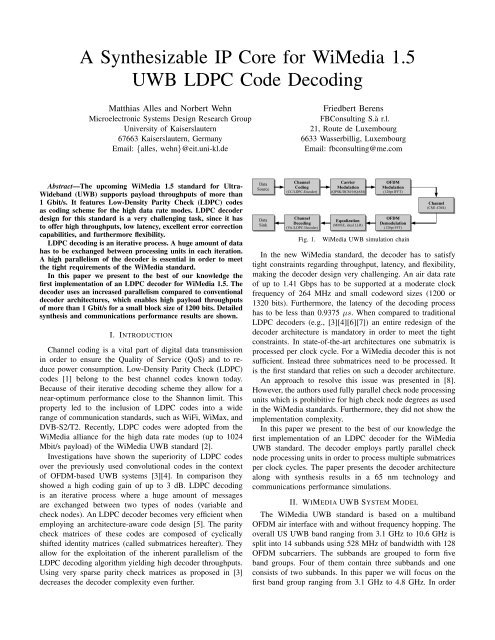
Fig. 1. <strong>WiMedia</strong> <strong>UWB</strong> simulation chain<br />
In the new <strong>WiMedia</strong> standard, the decoder has to satisfy<br />
tight constraints regarding throughput, latency, and flexibility,<br />
making the decoder design very challenging. An air data rate<br />
of up to 1.41 Gbps has to be supported at a moderate clock<br />
frequency of 264 MHz and small codeword sizes (1200 or<br />
1320 bits). Furthermore, the latency of the decoding process<br />
has to be less than 0.9375 µs. When compared to traditional<br />
<strong>LDPC</strong> decoders (e.g., [3][4][6][7]) an entire redesign of the<br />
decoder architecture is mandatory in order to meet the tight<br />
constraints. In state-of-the-art architectures one submatrix is<br />
processed per clock cycle. For a <strong>WiMedia</strong> decoder this is not<br />
sufficient. Instead three submatrices need to be processed. It<br />
is the first standard that relies on such a decoder architecture.<br />
An approach to resolve this issue was presented in [8].<br />
However,theauthorsusedfullyparallelchecknodeprocessing<br />
units which is prohibitive <strong>for</strong> high check node degrees as used<br />
in the <strong>WiMedia</strong> standards. Furthermore, they did not show the<br />
implementation complexity.<br />
In this paper we present to the best of our knowledge the<br />
first implementation of an <strong>LDPC</strong> decoder <strong>for</strong> the <strong>WiMedia</strong><br />
<strong>UWB</strong> standard. The decoder employs partly parallel check<br />
node processing units in order to process multiple submatrices<br />
per clock cycles. The paper presents the decoder architecture<br />
along with synthesis results in a 65 nm technology and<br />
communications per<strong>for</strong>mance simulations.<br />
II. WIMEDIA <strong>UWB</strong> SYSTEM MODEL<br />
The <strong>WiMedia</strong> <strong>UWB</strong> standard is based on a multiband<br />
OFDM air interface with and without frequency hopping. The<br />
overall US <strong>UWB</strong> band ranging from 3.1 GHz to 10.6 GHz is<br />
split into 14 subbands using 528 MHz of bandwidth with 128<br />
OFDM subcarriers. The subbands are grouped to <strong>for</strong>m five<br />
band groups. Four of them contain three subbands and one<br />
consists of two subbands. In this paper we will focus on the<br />
first band group ranging from 3.1 GHz to 4.8 GHz. In order
Channel Range RMS Average No. Transmission<br />
Model Delay of Paths Condition<br />
CM1 0-4 m 5 ns 21.4 Line-of-Sight (LoS)<br />
CM2 0-4 m 8 ns 37.2 Non LoS<br />
CM3 4-10 m 14 ns 62.7 Non LoS<br />
CM4 4-10 m 26 ns 122.8 Extreme Non LoS<br />
TABLE I<br />
IEEE CHANNEL MODELS FOR <strong>UWB</strong><br />
Parameter Value<br />
Payload data rate 53 Mbit/s to 1024 Mbit/s<br />
Data carriers 100<br />
FFT size 128 points<br />
Symbol Duration 312.5 ns (incl. Guard)<br />
Channel Coding CC with K = 7;<br />
<strong>LDPC</strong> <strong>Code</strong>s<br />
Carrier Modulation QPSK, DCM, 16QAM<br />
TABLE II<br />
WIMEDIA PHYSICAL LAYER PARAMETERS<br />
to evaluate the communications per<strong>for</strong>mance of the <strong>WiMedia</strong><br />
<strong>UWB</strong> standard a SystemC based simulation chain has been<br />
implemented. The basic structure of the simulation chain is<br />
depicted in Figure 1.<br />
The current <strong>WiMedia</strong> system uses standard convolutional<br />
coding. In <strong>WiMedia</strong> <strong>1.5</strong> <strong>LDPC</strong> codes were adopted <strong>for</strong> the<br />
high data rates (≥ 640 Mbit/s payload). After channel coding<br />
the coded data stream is interleaved and then mapped onto<br />
QPSK symbols <strong>for</strong> the lower data rates and DCM symbols <strong>for</strong><br />
the medium data rates ranging from 300 Mbit/s to 480 Mbit/s.<br />
For the high data rates 16QAM is used. These symbols are<br />
then used in the OFDM modulator to generate the OFDM<br />
symbols to be transmitted over the channel. The channel<br />
models used correspond to the IEEE 802.15.3a channels CM1<br />
to CM4. The main characteristics of these models are depicted<br />
in Table I. In the receiver the signal is demodulated and<br />
equalized deploying ideal channel estimation. The resulting<br />
demappedanddeinterleavedsoft-in<strong>for</strong>mationisthenprocessed<br />
by the channel decoder which is either a Viterbi decoder or<br />
an <strong>LDPC</strong> decoder. The <strong>WiMedia</strong> physical layer parameters are<br />
depicted in Table II.<br />
III. <strong>LDPC</strong> CODES<br />
<strong>LDPC</strong> codes [1] are linear block codes defined by a sparse<br />
parity check matrix H of size M × N, see Figure 2a). For<br />
binary <strong>LDPC</strong> codes a valid codeword �x has to satisfy H�x T =<br />
�0 in a modulo-2 arithmetic. A column in H is associated to a<br />
codeword bit, a row corresponds to a parity check. A non-zero<br />
element in a row means that the corresponding bit contributes<br />
to this parity check. Typically, 2% or less of the elements of<br />
H are non-zero.<br />
ThecompletecodecanbebestvisualizedbyaTannergraph,<br />
a graphical representation of the associations between code<br />
bits and parity checks. Each column of H corresponds to a<br />
variable node (VN) and represents one code bit, each row<br />
of H corresponds to a check node (CN) and represents one<br />
parity check, respectively. Edges connect variable and check<br />
nodes according to the non-zero elements of the parity check<br />
Fig. 2. Tanner graph of an irregular <strong>LDPC</strong> code<br />
matrix. Figure 2b) shows the corresponding Tanner graph to<br />
the parity check matrix in Figure 2a) of an <strong>LDPC</strong> code with<br />
N = 7 variable nodes and M = 3 check nodes. The resulting<br />
code rate is R = (N − M)/N = 4/7.<br />
A. <strong>LDPC</strong> <strong>Decoding</strong><br />
<strong>LDPC</strong> codes can be decoded using the Sum-Product algorithm<br />
(SPA) [1]. Soft in<strong>for</strong>mation is exchanged iteratively<br />
between variable and check nodes. To reduce the implementation<br />
complexity the SPA is trans<strong>for</strong>med into the logarithmic<br />
domain.<br />
<strong>Decoding</strong> works as follows: The variable node n is ini-<br />
tialized with the corresponding log-likelihood ratio (LLR) of<br />
the received bit λ ch<br />
n . Next, messages are propagated from<br />
the variable nodes to the check nodes via the edges of the<br />
Tanner graph. For the first iteration the messages sent by the<br />
variable node n via its edges to the connected check nodes m.<br />
λn→m = λ ch<br />
n . The check node m computes new messages <strong>for</strong><br />
thevariable nodes.Duetothehighimplementation complexity<br />
of the optimal belief propagation algorithm, suboptimal algorithms<br />
are used <strong>for</strong> the check node implementation. We use<br />
the normalized Min-Sum algorithm [9] where only the two<br />
smallest magnitudes are used:<br />
⎛<br />
λm→n = α × ⎝ �<br />
n ′ ∈N(m)\n<br />
× min<br />
n ′ ∈N(m)\n (|λn ′ →m|) ,<br />
⎞<br />
sgn(λn ′ →m) ⎠ (1)<br />
with N(m) the set of variable nodes connected to the check<br />
node m. When using the extrinsic scaling factor α, a communications<br />
per<strong>for</strong>mance close to the optimal algorithm is<br />
achievable. Typically, α is chosen as 0.75 or 0.875, since these<br />
values are easy to implement.<br />
Then, the variable nodes compute an overall estimation of<br />
the decoded bit (a posteriori probability, APP) by adding up<br />
the extrinsic in<strong>for</strong>mation of all connected check nodes to the<br />
channel value:<br />
Λn = λ ch<br />
n + �<br />
λm ′ →n, (2)<br />
m ′ ∈M(n)<br />
with M(n) the set of check nodes connected to the variable<br />
node n. The sign of Λn can be understood as the hard decision
Check Nodes<br />
0<br />
24<br />
48<br />
72<br />
96<br />
120<br />
144<br />
168<br />
192<br />
216<br />
240<br />
264<br />
288<br />
0 24 48 72 96 120 144 168 192 216 240 264 288 312 336 360 384 408 432 456 480 504 528 552 576<br />
Variable Nodes<br />
Fig. 3. A parity check matrix of the WiMAX code with P = 24.<br />
on the decoded bit. New messages λn→m are then computed<br />
following the extrinsic principle:<br />
λn→m = λ ch<br />
n + �<br />
λm ′ →n = Λn − λm→n. (3)<br />
m ′ ∈M(n)\m<br />
The decoding process is stopped after a maximum number of<br />
iterations or earlier if the parity check is satisfied.<br />
B. Layered <strong>Decoding</strong><br />
Updating the variable and check nodes can be done with a<br />
two-phase scheduling: In the first phase all variable nodes are<br />
updated, in the second phase all check nodes, respectively. To<br />
improve the communications per<strong>for</strong>mance <strong>for</strong> a given number<br />
of iterations turbo decoding message passing (TDMP) [5],<br />
which is also known as layered decoding, shuffled decoding or<br />
Gauss-Seidel iterations, is used. The idea is to take intermediate<br />
results of the calculations into account still in the same<br />
iteration. Consider we are processing one check node. After<br />
computing new LLRs, they are sent back to the connected<br />
variable nodes immediately. These variable nodes update their<br />
outgoing edges, such that the other check nodes connected to<br />
these variable nodes will receive already updated results. With<br />
this technique it is possible to reduce the number of iterations<br />
by up to 50 % at a fixed communications per<strong>for</strong>mance. The<br />
achieved gain in convergence speed can thus be used to reduce<br />
the latency or to increase the throughput of the decoding<br />
process (valid <strong>for</strong> software as well as hardware decoders).<br />
C. Structured <strong>LDPC</strong> <strong>Code</strong>s<br />
A random connectivity between variable and check nodes<br />
poses big challenges <strong>for</strong> an efficient hardware implementation.<br />
Complex connectivity networks become mandatory to allow<br />
<strong>for</strong> a flexible and parallel message exchange, resolving occurring<br />
memory access conflicts. Thus, <strong>LDPC</strong> codes defined<br />
by standards are based on so called structured <strong>LDPC</strong> codes<br />
[10]. The matrices of these codes are composed of cyclically<br />
shifted identity matrices of size P × P, see Figure 3.<br />
These codes allow <strong>for</strong> an efficient implementation of the<br />
connectivity between up to P variable and P check nodes.<br />
Memory access conflicts are avoided and a low complexity<br />
logarithmic barrel shifter is sufficient as connectivity network<br />
<strong>for</strong> a given P. Furthermore, storing the parity check matrix<br />
is simplified. Only the positions of the cyclically shifted<br />
identity matrices and the corresponding shift value have to<br />
Block <strong>Code</strong> Edges P Variable Node Check Node<br />
Size N Rate R Degrees Degrees<br />
1200 1/2 3510 30 2,3,4 5,6<br />
1200 5/8 3720 30 2,3,4 8,9<br />
1200 3/4 3600 30 2,3,4 12<br />
1200 4/5 3510 30 2,3,4 12,15<br />
1320 5/11 4320 30 2,3,4,5 5,6<br />
1320 25/44 4770 30 2,3,4,5 8,9<br />
1320 15/22 4650 30 2,3,4 7,8,9,11,12<br />
1320 8/11 4650 30 2,3,4 7,9,11,12,15<br />
TABLE III<br />
WIMEDIA <strong>LDPC</strong> CODE PARAMETERS<br />
be stored. In Figure 3 these pairs <strong>for</strong> the check nodes 0 to 23<br />
are (a,s) = {(1,23),(2,18),(8,13),(9,20),(12,1),(13,0)},<br />
with a addressing the set of variable nodes and s the shift<br />
offset.<br />
D. <strong>WiMedia</strong> <strong>LDPC</strong> <strong>Code</strong>s<br />
The <strong>WiMedia</strong> matrices are structured ones with P = 30 and<br />
look very much the same as in the WiMax standard. At the<br />
moment they are still under non-disclosure. In the <strong>WiMedia</strong><br />
standard, eight <strong>LDPC</strong> codes are provided, see Table III. Two<br />
block lengths (N = 1200, N = 1320) are defined, each<br />
offering four different code rates. As proposed in [3], the<br />
matrices are very sparse and only about 1% of the matrix<br />
entries are non-zero. Due to the high sparseness the decoder<br />
complexity is reduced and the decoding process is accelerated,<br />
since less edges have to be processed by the decoder. The high<br />
block length is optional and obtained by encoding a full 1200<br />
bit codeword a second time with a code rate of 10/11. The 120<br />
additional parity bits are transmitted via the guard carriers.<br />
IV. DECODER ARCHITECTURE<br />
The implementation of <strong>LDPC</strong> decoders is either done in a<br />
fully parallel or partly parallel way. Fully parallel architectures<br />
instantiate all nodes of the Tanner graph. However, the large<br />
area, routing congestions and the lack of flexibility make this<br />
approach prohibitive [11]. Partly parallel architectures become<br />
mandatory where only a subset of VNs and CNs is instantiated<br />
through functional units (FU). The nodes of the Tanner graph<br />
are processed in a time multiplexed way on the FUs. Messages<br />
andAPPvaluesarestoredinRAMsandaccessedwhenneeded<br />
by the FUs. A permutation network has to be used, that is<br />
capable to establish the correct connections between the FUs.<br />
Structured <strong>LDPC</strong> codes allow to replace complicated flexible<br />
networks by a low complex logarithmic barrel shifter with P<br />
inputs [10].<br />
In state-of-the-art layered <strong>LDPC</strong> decoders, one submatrix<br />
(equal to P edges) is processed per clock cycle. This corresponds<br />
to serial working FUs that are capable to read/write<br />
one edge per clock cycle. In order to obtain high throughputs,<br />
P can be increased when designing a code. But increasing<br />
P is a trade-off between block length and communications<br />
per<strong>for</strong>mance. A high P at a low block length will result in<br />
a poor communications per<strong>for</strong>mance, due to the low degree<br />
of freedom when designing the code (the parity check matrix<br />
is composed of only a few submatrices then). Thus, a high
Fig. 4. Layered decoder architecture with partly parallel check nodes<br />
P requires a large block length in order to obtain reasonable<br />
per<strong>for</strong>mance. For the <strong>WiMedia</strong> standard, however, the block<br />
length is fixed to 1200 bits because of the given framing<br />
structure. Due to this small block size it is not possible to<br />
increase P much beyond 30 by code design without sacrificing<br />
communications per<strong>for</strong>mance. Instead, the high throughput<br />
and the low latency constraints of <strong>WiMedia</strong> make the processing<br />
of multiple submatrices per clock cycles necessary.<br />
Figure 4 shows our <strong>WiMedia</strong> layered decoder architecture.<br />
The decoder consists of three slots, each capable of processing<br />
one submatrix (= 30 edges <strong>for</strong> <strong>WiMedia</strong>) per clock cycle.<br />
No explicit FUs <strong>for</strong> the variable nodes exist in the decoder.<br />
Instead the variable node operations according to Equation 2<br />
and Equation 3 are processed in the 30 check node blocks<br />
(CNBs). The check node FUs (CFUs) contain the check node<br />
functionality, i.e., they per<strong>for</strong>m the minimum search and the<br />
parity check. In our decoder, each CNB is capable to read and<br />
write three edges per clock cycle, while each edge stems from<br />
a different slot. Thus, the decoder allows <strong>for</strong> the processing<br />
of 90 edges per clock cycle. This parallelism yields the high<br />
throughput and low latency required, despite thelow codeword<br />
and submatrix sizes. The minimum search within the CFU is<br />
per<strong>for</strong>med according to [12].<br />
Each slot holds one third of the variable node estimations<br />
Λn in its APP RAM, with P = 30 APP values per address.<br />
Slot 0 stores the 3 ∗ith submatrix columns of the parity check<br />
matrix, i.e., it holds the APP in<strong>for</strong>mation Λ0 to Λ29 at address<br />
0, Λ90 to Λ119 at address 1, and so on. Slot 1 stores the<br />
(3 ∗ i + 1)th submatrix columns of the parity check matrix,<br />
i.e., it holds the APP in<strong>for</strong>mation Λ30 to Λ59, Λ120 to Λ149,<br />
etc. Finally, slot 2 holds the rest of the APP in<strong>for</strong>mation, i.e.,<br />
the (3 ∗ i + 2)th submatrix columns. By addressing the APP<br />
RAM and shifting the output into the appropriate order, each<br />
CNB receives the correct APP in<strong>for</strong>mation.<br />
Each slot has own address and permutation RAMs to store<br />
its portion of the parity check matrix. The content of these<br />
RAMs can be directly derived from the parity check matrix,<br />
as shown in Figure 3. Figure 5a) shows the address and<br />
shift vectors <strong>for</strong> the WiMax code <strong>for</strong> a decoder architecture<br />
Fig. 5. Parity check matrix storage of WiMax code <strong>for</strong> decoder architecture<br />
with a) one slot b) three slots<br />
that consists of a single slot. At each address of the address<br />
and permutation RAM the position and the shift value <strong>for</strong><br />
a single submatrix is stored. The horizontal lines indicate the<br />
beginning/end of a check node. In Figure 5b) the same code is<br />
processed on the proposed architecture with three slots. Taking<br />
the address in Figure 5a) modulo three gives the slot where<br />
this submatrix will be processed. Finally, dividing this address<br />
by three will give the new address <strong>for</strong> the target slot. The<br />
permutation values are not affected by this trans<strong>for</strong>mation.<br />
Using three slots instead of a single one, obviously leads<br />
to a significant acceleration of the decoding process. For the<br />
first check node group, only two instead of six clock cycles<br />
are necessary <strong>for</strong> reading the APP in<strong>for</strong>mation. In case the<br />
memory accesses are not equally distributed to the slots (e.g.,<br />
the check node degree is not divisible by three), the address<br />
vector is filled up with -1, see slot 0. For the decoder this<br />
means not to access the APP RAMs and to insert a nooperation<br />
cycle <strong>for</strong> this slot.<br />
The <strong>WiMedia</strong> codes were designed with respect to a stallfree<br />
decoder architecture. In Figure 5b), which shows the<br />
WiMax code, the decoder will have to stall between the first<br />
twochecknodes.Thereasonisthat<strong>for</strong>slot1bothchecknodes<br />
access the APP RAM at address 0. The second read access,<br />
however, must not be executed be<strong>for</strong>e the first check node has<br />
written back its updated in<strong>for</strong>mation to the APP RAM. Due to<br />
the delay of several clock cycles while decoding, stall cycles<br />
have to be introduced in this case. For <strong>WiMedia</strong>, the check<br />
node processing can be scheduled in such a way that accessing<br />
the same APP in<strong>for</strong>mation only happens, when the result was<br />
written back be<strong>for</strong>e. No stall cycles have to be introduced,<br />
which results in a high utilization of the functional units.<br />
A. Implementation<br />
V. RESULTS<br />
The presented <strong>WiMedia</strong> <strong>LDPC</strong> decoder was implemented in<br />
synthesizable VHDL code and synthesized in a 65 nm CMOS<br />
low power technology. The following constraints are satisfied:<br />
• <strong>Code</strong> rate flexibility<br />
• <strong>Code</strong>word size flexibility (1200 bits and 1320 bits)<br />
• Clock frequency of 264 MHz<br />
• Air throughput of 1.28 Gbps <strong>for</strong> short blocks<br />
• Air throughput of 1.41 Gbps <strong>for</strong> long blocks
Block <strong>Code</strong> No. of Clock Latency / Throughput / Gbps<br />
Size N Rate R Iter. Cycles µs Air Payload<br />
1200 1/2 5 219 0.83 1.44 0.72<br />
1200 5/8 5 247 0.93 1.28 0.80<br />
1200 3/4 5 226 0.86 1.40 1.05<br />
1200 4/5 5 227 0.86 1.40 1.12<br />
1320 5/11 4 211 0.80 1.65 0.75<br />
1320 25/44 3 193 0.73 1.80 1.02<br />
1320 15/22 3 194 0.74 1.79 1.22<br />
1320 8/11 3 207 0.78 1.68 1.22<br />
TABLE IV<br />
THROUGHPUT RESULTS FOR 264 MHZ CLOCK FREQUENCY<br />
<strong>LDPC</strong> <strong>Code</strong> <strong>WiMedia</strong> <strong>1.5</strong><br />
No. of Slots 3<br />
Slot Parallelism 30<br />
Input Quantization 5 bit<br />
APP Quantization 7 bit<br />
Algorithm MinSum, ESF=0.875<br />
Throughput see Table IV<br />
Comm. Per<strong>for</strong>mance see Figure 6<br />
Area[mm 2 ] 65nm@264MHz<br />
CNB Logic 0.08<br />
Controller Logic 0.02<br />
Networks 0.02<br />
APP RAMs 0.18<br />
CNB RAMs 0.16<br />
<strong>Code</strong> Vectors 0.04<br />
Overall Logic 0.12 (23.5%)<br />
Overall Memory 0.39 (76.5%)<br />
Overall Area 0.51 (100%)<br />
TABLE V<br />
SYNTHESIS RESULTS FOR THE WIMEDIA <strong>1.5</strong> <strong>LDPC</strong> DECODER<br />
• Latency less than 0.9375 µs (247 clock cycles)<br />
Table IV gives the obtained throughput and latency results<br />
<strong>for</strong> the six codes defined by the standard. Double buffering is<br />
applied in order to hide the input interface latency. Payload<br />
throughputs of more than 1 Gbps are obtained.<br />
The core was synthesized in a 65 nm low power technology,<br />
see Table V. Overall, the decoder takes 0.51 mm 2 after<br />
synthesis. 76.5% (0.39 mm 2 ) are caused by the memories<br />
and only 23.5% (0.12 mm 2 ) come from logic. The memory<br />
dominationiscausedbyitsdisadvantageousaspectratios.E.g.,<br />
the APP RAMs are only 16 entries deep but 210 bit wide,<br />
resulting in inefficient bit densities and yielding the high area.<br />
B. Communications Per<strong>for</strong>mance<br />
Figure 6 shows the communications per<strong>for</strong>mance of the<br />
short <strong>LDPC</strong> codes. The results were obtained using the <strong>UWB</strong><br />
simulationchainasshowninFigure1withaCM1channeland<br />
a bit-accurate <strong>LDPC</strong> decoder model. For comparison reasons<br />
the per<strong>for</strong>mance of a rate 3/4 convolutional code (64 states)<br />
is also shown. Compared to the corresponding <strong>LDPC</strong> code a<br />
coding gain of 4 dB (PER 10 −1 ) to 6 dB (PER 10 −3 ) can be<br />
observed.<br />
VI. CONCLUSION<br />
In this paper we presented to the best of our knowledge the<br />
first implementation of a <strong>WiMedia</strong> <strong>1.5</strong> <strong>UWB</strong> <strong>LDPC</strong> decoder.<br />
The decoder allows <strong>for</strong> payload throughputs beyond 1 Gbit/s<br />
10 0<br />
10 −1<br />
PER<br />
10 −2<br />
10 −3<br />
<strong>WiMedia</strong> <strong>LDPC</strong> <strong>Code</strong>s, 1200 bits, CM1, 16−QAM<br />
<strong>LDPC</strong>, R=1/2, 5 iterations<br />
<strong>LDPC</strong>, R=5/8, 5 iterations<br />
<strong>LDPC</strong>, R=3/4, 5 iterations<br />
<strong>LDPC</strong>, R=4/5, 5 iterations<br />
CC, R=3/4<br />
14 16 18 20 22 24 26 28<br />
E /N [dB]<br />
B 0<br />
Fig. 6. Per<strong>for</strong>mance results <strong>for</strong> <strong>WiMedia</strong> <strong>LDPC</strong> codes<br />
despite the small block length of 1200 bits and the moderate<br />
clock frequency of 264 MHz. It offers all the flexibility<br />
required by the standard. The overall area of the decoder<br />
is 0.51 mm 2 after synthesis in a 65 nm low power CMOS<br />
technology. It is dominated by the memories (76.5%).<br />
REFERENCES<br />
[1] R. G. Gallager, “Low-Density Parity-Check <strong>Code</strong>s,” IRE Transactions<br />
on In<strong>for</strong>mation Theory, vol. 8, no. 1, pp. 21–28, January 1962.<br />
[2] Standard ECMA-368, “High Rate Ultra Wideband PHY and MAC<br />
Standard.” [Online]. Available: http://www.ecma-international.org<br />
[3] T. Brack, F. Kienle, T. Lehnigk-Emden, M. Alles, N. Wehn, and<br />
F. Berens, “Enhanced Channel Coding <strong>for</strong> OFDM-based <strong>UWB</strong> Systems,”<br />
in Proc. International Conference on Ultra-Wideband (IC<strong>UWB</strong><br />
2006), Waltham, Massachusetts, Sep. 2006, pp. 255–260.<br />
[4] T. Brack, M. Alles, T. Lehnigk-Emden, F. Kienle, N. Wehn, F. Berens,<br />
and A. Ruegg, “A Survey on <strong>LDPC</strong> <strong>Code</strong>s and Decoders <strong>for</strong> OFDMbased<br />
<strong>UWB</strong> Systems,” in Proc. 56th Vehicular Technology Conference<br />
(VTC Spring ’07), Dublin, Ireland, Apr. 2007.<br />
[5] M. Mansour and N. Shanbhag, “Architecture-Aware Low-Density<br />
Parity-Check <strong>Code</strong>s,” in Proc. 2003 IEEE International Symposium on<br />
Circuits and Systems (ISCAS ’03), Bangkok, Thailand, May 2003.<br />
[6] G. Gentile, M. Rovini, and L. Fanucci, “Low-Complexity Architectures<br />
of a Decoder <strong>for</strong> IEEE 802.16e <strong>LDPC</strong> <strong>Code</strong>s,” in Digital System Design<br />
Architectures, Methods and Tools, 2007. DSD 2007. 10th Euromicro<br />
Conference on, Lübeck, Germany, Aug. 2007, pp. 369–375.<br />
[7] P. Urard, L. Paumier, V. Heinrich, N. Raina, and N. Chawla, “A<br />
360mW 105Mb/s DVB-S2 Compliant <strong>Code</strong>c based on 64800b <strong>LDPC</strong><br />
and BCH <strong>Code</strong>s enabling Satellite-Transmission Portable Devices,”<br />
in Proc. Digest of Technical Papers. IEEE International Solid-State<br />
Circuits Conference ISSCC 2008, 3–7 Feb. 2008, pp. 310–311.<br />
[8] S. Kim, G. E. Sobelman, and H. Lee, “Flexible <strong>LDPC</strong> Decoder Architecture<br />
<strong>for</strong> High-Throughput Applications,” in Proc. IEEE Asia Pacific<br />
Conference on Circuits and Systems APCCAS 2008, Nov. 2008, pp. 45–<br />
48.<br />
[9] J. Chen, A. Dholakia, E. Eleftheriou, M. P. C. Fossorier, and X.-Y. Hu,<br />
“Reduced-Complexity <strong>Decoding</strong> of <strong>LDPC</strong> <strong>Code</strong>s,” IEEE Transactions<br />
on Communications, vol. 53, no. 8, pp. 1288–1299, Aug. 2005.<br />
[10] E. Boutillon, J. Castura, and F. Kschischang, “Decoder-first code design,”<br />
in Proc. 2nd International Symposium on Turbo <strong>Code</strong>s & Related<br />
Topics, Brest, France, Sep. 2000, pp. 459–462.<br />
[11] A. Blanksby and C. J. Howland, “A 690-mW 1-Gb/s, Rate-1/2 Low-<br />
Density Parity-Check <strong>Code</strong> Decoder,” IEEE Journal of Solid-State<br />
Circuits, vol. 37, no. 3, pp. 404–412, Mar. 2002.<br />
[12] X.-Y. Shih, C.-Z. Zhan, C.-H. Lin, and A.-Y. Wu, “An 8.29 mm 52 mW<br />
Multi-Mode <strong>LDPC</strong> Decoder Design <strong>for</strong> Mobile WiMAX System in 0.13<br />
& CMOS Process,” IEEE Journal of Solid-State Circuits, vol. 43, no. 3,<br />
pp. 672–683, March 2008.