Inrush Current Control Technology Boosts Power Converter Reliability
Inrush Current Control Technology Boosts Power Converter Reliability
Inrush Current Control Technology Boosts Power Converter Reliability

Create successful ePaper yourself
Turn your PDF publications into a flip-book with our unique Google optimized e-Paper software.
Special Feature<br />
0<br />
0<br />
Figure 2<br />
cessively high current peaks and may meet<br />
system specifications without additional<br />
protection. While the peak inrush current<br />
must be tested for spec compliance,<br />
the i 2 t of the current waveform should also<br />
be evaluated, as it could trip an upstream<br />
fuse, circuit breaker or SSPC.<br />
Turn-On <strong>Current</strong><br />
The second current peak is also considered<br />
part of the inrush current. This peak<br />
[ 30 ] COTS Journal November 2011<br />
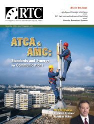
Typical inrush current waveform<br />
inrush spike<br />
Shown here is the waveform of a typical power system’s inrush current. It has two current<br />
peaks. The first “inrush spike” peak current occurs when the input voltage source is turned<br />
on.<br />
Figure 3<br />
large load<br />
capacitance<br />
Typical turn-on current waveform<br />
normal<br />
In this waveform of a typical turn-on current, turn-on current is the same whether the<br />
converter is turned on by applying an input voltage or via an enable/inhibit signal.<br />
occurs when the DC/DC converter turns<br />
on and draws current from the source to<br />
charge its output capacitance and any load<br />
capacitance. Typical turn-on current waveforms<br />
are shown in Figure 3. The turn-on<br />
current is the same whether the converter<br />
is turned on by applying an input voltage<br />
or via an enable/inhibit signal. The turnon<br />
current waveshape and peak value will<br />
be well-controlled as long as the converter<br />
has an output soft start feature. But it could<br />
require a higher peak current when starting<br />
into a large capacitive load.<br />
VPT’s DC/DC converters, for example,<br />
use a proprietary magnetic feedback<br />
scheme with a well-controlled internal<br />
start-up sequence and a precise output<br />
voltage soft start feature. The voltage soft<br />
start feature ensures the output ramps up<br />
in a controlled manner, with controlled dv/<br />
dt. Due to the soft start, the input current<br />
usually does not exceed the steady state input<br />
current of the converter during turnon.<br />
These DC/DC converters also feature<br />
continuous constant output current limit.<br />
They will supply full rated current into any<br />
load; they do not hiccup or shut down and<br />
restart. This allows them to start any load<br />
capacitor, regardless of size. For cases with<br />
very large load capacitance, the DC/DC<br />
converter might enter this constant current<br />
limit mode during turn-on. In this case the<br />
input current would not exceed approximately<br />
1.5 times the steady state input current.<br />
This is not high enough to cause any<br />
interference or trip upstream protection<br />
devices. For VPT’s DC/DC converters, this<br />
second inrush peak will not cause adverse<br />
effects in the system design.<br />
Active <strong>Inrush</strong> Limiting<br />
In some applications there is a requirement<br />
to limit the inrush spike current<br />
into the input capacitors. The only<br />
way to accomplish this is to insert a series<br />
element into the circuit in front of those<br />
capacitors. There are several approaches:<br />
a resistor with a bypass switch, an inductor,<br />
a controlled MOSFET, or a dedicated<br />
inrush current protection module. In a<br />
basic inrush limiting circuit using a series<br />
resistor and a bypass switch, the resistor<br />
will limit the input current until the<br />
input capacitors are charged. The switch<br />
will then close to allow the full current<br />
to flow to the downstream DC/DC converter.<br />
The switch can be a relay or semiconductor<br />
switch, and can be driven from<br />
the 28V input such that it is somewhat automatically<br />
controlled. The resistor also<br />
can be replaced with a positive (PTC) or<br />
negative temperature coefficient (NTC)<br />
thermistor. The NTC thermistor does not<br />
require a bypassing switch S1, but does require<br />
time to cool after power is removed,<br />
before it is functional again.