Special Report – Automotive Electronics - Power Systems Design
Special Report – Automotive Electronics - Power Systems Design
Special Report – Automotive Electronics - Power Systems Design

Create successful ePaper yourself
Turn your PDF publications into a flip-book with our unique Google optimized e-Paper software.
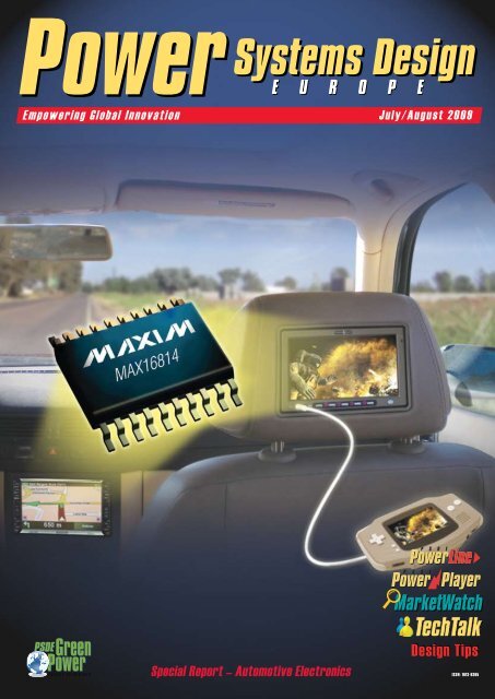
E m p o w e r i n g G l o b a l I n n o v a t i o n J u l y / A u g u s t 2 0 0 9<br />
<strong>Special</strong> <strong>Report</strong> <strong>–</strong> <strong>Automotive</strong> <strong>Electronics</strong><br />
<strong>Design</strong> Tips<br />
<strong>Design</strong> Tips<br />
ISSN: 1613-6365
Dilbert <strong>–</strong> 56<br />
Viewpoint<br />
Auto-Anticipation By Cliff Keys, Editor-in-Chief, PSDE ............................................................................................................................................4<br />
Industry News<br />
Abengoa Solar Inaugurates 2 nd -Generation Solar Tower ..........................................................................................................................................6<br />
Digi-Key Announces Expansion of Distribution Agreement with GE Sensing & Inspection Technologies ...............................................................6<br />
Solyndra Signs $115 Million Contract with Ebitschenergietechnik ...........................................................................................................................6<br />
Osram Showcases Siemens’ Hamburg Office ..........................................................................................................................................................8<br />
PCIM Europe 2010 Call for Papers ...........................................................................................................................................................................8<br />
Linear’s New UltraFast Digitally Programmable 5A LDO .....................................................................................................................................10<br />
Time for <strong>Automotive</strong> Innovation, By Dr. Henning Hauenstein, International Rectifier .............................................................................................11<br />
Key Trends Offer Hope to Depressed <strong>Automotive</strong> Suppliers, By Jon Cropley, IMS Research ...............................................................................12<br />
<strong>Design</strong> Tips<br />
Frequency Response of Switching <strong>Power</strong> Supplies - Part 6, By Dr. Ray Ridley, Ridley Engineering .....................................................................14<br />
On The Road<br />
Texas Instruments, Vincotech, Vicor, <strong>Report</strong>ed By Cliff Keys, Editor-in-Chief, PSDE ............................................................................................18<br />
New ISOpro Family from Silicon Labs, <strong>Report</strong>ed By Cliff Keys, Editor-in-Chief, PSDE .........................................................................................21<br />
<strong>Power</strong>vation’s Uniquely Digital <strong>Power</strong>, <strong>Report</strong>ed By Cliff Keys, Editor-in-Chief, PSDE ..........................................................................................22<br />
TSMC <strong>Power</strong>s Forward with R&D, <strong>Report</strong>ed By Cliff Keys, Editor-in-Chief, PSDE ................................................................................................24<br />
XP <strong>Power</strong> Moves Ahead in Medical, <strong>Report</strong>ed By Cliff Keys, Editor-in-Chief, PSDE .............................................................................................26<br />
Cover Story<br />
Integrating HB LEDs in Automobile <strong>Systems</strong> ..........................................................................................................................................................28<br />
<strong>Special</strong> <strong>Report</strong> - Green <strong>Power</strong><br />
<strong>Power</strong>ing <strong>Automotive</strong>, By Dipl.-Ing Jan Micheal Weickhmann, Vacuumschmelze GmbH ......................................................................................35<br />
Rugged and Reliable Motor Drive Solutions, By Dr. Henning Hauenstein and Marco Giandalia, International Rectifier........................................37<br />
LED Biasing in <strong>Automotive</strong> Applications, By Brian Blackburn, ON Semiconductor ...............................................................................................40<br />
Addressing <strong>Automotive</strong> Safely, By Wayne Lyons, ARM ..........................................................................................................................................43<br />
<strong>Automotive</strong> Education, By Paul De Meulenaere, <strong>Automotive</strong> ICT, Sofie Krol, Karel de Grote-University College Antwerp, Belgium, and David<br />
Perry, University of Valencia, Spain .........................................................................................................................................................................46<br />
<strong>Automotive</strong> Industry Woes, By George Karalias, Rochester <strong>Electronics</strong> ................................................................................................................48<br />
From Russia with <strong>Automotive</strong>, By Stanislav N. Florentsev, Ruselprom-ElectricDrive Ltd. .....................................................................................50<br />
<strong>Automotive</strong> Infotainment LCD-TFT Panels, By Keff Gruetter, Linear Corporation ..................................................................................................52<br />
Are We Really Serious? <strong>Report</strong>ed By Cliff Keys, Editor-in-Chief, PSDE .................................................................................................................56<br />
New Products<br />
Web Exclusive Content: www.powersystemsdesign.com<br />
Member<br />
Arnold Alderman<br />
Heinz Rüedi<br />
Marion Limmer<br />
Eric Lidow<br />
Dr. Leo Lorenz<br />
Davin Lee<br />
Tony Armstrong<br />
Hans D. Huber<br />
Andrew Cowell<br />
<strong>Power</strong> <strong>Systems</strong> <strong>Design</strong> Europe Advisory Board<br />
Representing<br />
Anagenesis<br />
CT-Concept Technology<br />
Fairchild Semiconductor<br />
Industry Luminary<br />
Infineon Technologies<br />
Intersil<br />
Linear Technology<br />
LEM<br />
Micrel<br />
Member<br />
Michele Sclocchi<br />
Mike Noonen<br />
Kirk Schwiebert<br />
Christophe Basso<br />
Balu Balakrishnan<br />
Paul Greenland<br />
Uwe Mengelkamp<br />
Peter Sontheimer<br />
Representing<br />
National Semiconductor<br />
NXP Semiconductors<br />
Ohmite<br />
On Semiconductor<br />
<strong>Power</strong> Integrations<br />
Semtech<br />
Texas Instruments<br />
Tyco <strong>Electronics</strong>
VIEWPOINT<br />
AGS Media Group<br />
146 Charles Street<br />
Annapolis, Maryland 21401 USA<br />
Tel: +410-295-0177<br />
Fax: +510-217-3608<br />
www.powersystemsdesign.com<br />
Editorial Director, <strong>Power</strong> <strong>Systems</strong> <strong>Design</strong><br />
China, Europe & North America<br />
Editor-in-Chief, <strong>Power</strong> <strong>Systems</strong> <strong>Design</strong><br />
Europe & North America<br />
Cliff Keys<br />
cliff.keys@powersystemsdesign.com<br />
Contributing Editors<br />
Liu Hong<br />
Editor-in-Chief, <strong>Power</strong> <strong>Systems</strong> <strong>Design</strong> China<br />
powersdc@126.com<br />
Ash Sharma, IMS Research<br />
ash.sharma@imsresearch.com<br />
Dr. Ray Ridley, Ridley Engineering<br />
RRidley@ridleyengineering.com<br />
Publishing Director<br />
Jim Graham<br />
jim.graham@powersystemsdesign.com<br />
Publisher<br />
Julia Stocks<br />
julia.stocks@powersystemsdesign.com<br />
Circulation Management<br />
Kathryn Phillips<br />
kathryn.phillips@powersystemsdesign.com<br />
Research Director<br />
Meghan Corneal<br />
meghan.corneal@powersystemsdesign.com<br />
Magazine <strong>Design</strong><br />
Beata Rasmus, Eyemotive<br />
beata@eyemotive.com<br />
Production Manager<br />
Abby Wang<br />
abbyw@action-new.net<br />
Registration of copyright: January 2004<br />
ISSN number: 1613-6365<br />
AGS Media Group and <strong>Power</strong> <strong>Systems</strong> <strong>Design</strong> Europe<br />
magazine assume and hereby disclaim any liability to<br />
any person for any loss or damage by errors or omis-<br />
sions in the material contained herein regardless of<br />
whether such errors result from negligence, accident<br />
or any other cause whatsoever.<br />
Send address changes to:<br />
circulation@powersystemsdesign.com<br />
Free Magazine Subscription,<br />
go to: www.powersystemsdesign.com<br />
Volume 6, Issue 6<br />
Cover graphics courtesey of Analog Devices, Inc.<br />
All rights reserved and respective partiies.<br />
Auto-Anticipation…<br />
Welcome to this very full <strong>Automotive</strong>themed<br />
issue of <strong>Power</strong> <strong>Systems</strong> <strong>Design</strong>,<br />
featuring a full print issue and even more<br />
to be found online on our website.<br />
Certainly we have already seen many<br />
changes in this industry, particularly in<br />
the US where controversy continues on<br />
the bail outs and the future of this onceproud<br />
industry.<br />
The Western European auto<br />
industry has also been hit hard by<br />
the worldwide recession; government<br />
stimulus packages in Germany and<br />
France are mitigating the downturn in<br />
those nations, according to iSuppli. For<br />
2009 sales are expected to fall by 16.7<br />
percent, but as the economy recovers,<br />
regional auto sales are projected to<br />
increase slowly starting in 2010 and will<br />
return to nearly the 2008 sales level by<br />
2014.<br />
Governments are desperately trying to<br />
help stabilize their valuable auto markets<br />
during the recession with incentives that<br />
give buyers of new cars a discount if<br />
they trade in old cars that generate more<br />
air pollution than new, cleaner vehicles.<br />
The results are encouraging, particularly<br />
in Germany where an incentive of 2,500<br />
euros for a new car commenced in mid<br />
January and immediately impacted<br />
sales. France’s incentive, which<br />
started in December, 2008, was much<br />
smaller at 1,000 euros, so its impact<br />
was somewhat lessened compared to<br />
Germany. Time will tell.<br />
Despite the uncertainty and<br />
anticipation, we have a huge crop of<br />
contributions from our industry in this<br />
issue. The need for automobiles, like all<br />
products, falls in recession, but the need<br />
for differentiation goes on. The huge and<br />
increasing volume of power electronics<br />
in vehicles, even conventionally powered<br />
cars, is still rising. With the regulatory<br />
and environmental requirements for<br />
‘cleaner and leaner’ designs and the<br />
advent of HEVs and electric vehicles,<br />
this requirement will not die.<br />
Of course, we are all painfully<br />
aware that at the moment, business<br />
is suffering on many fronts; times are<br />
hard, shareholders need to be pleased,<br />
spreadsheets satisfied and as a result,<br />
many talented people are ‘let go’. Short<br />
term fixes such as these are widespread.<br />
But this often spurs those same<br />
innovative and creative engineers<br />
to deploy their valuable skills in a<br />
more productive way; to utilize their<br />
outstanding engineering talents to<br />
develop designs for the good of the<br />
environment and its people in smaller,<br />
more responsible companies, design<br />
consultancies and start-ups, rather than<br />
just to satisfy the investors. There are<br />
more and more examples of this to be<br />
found within our industry and naturally,<br />
within our magazine.<br />
I hope you enjoy this issue, please<br />
keep your feedback coming, check out<br />
the expanded online content and don’t<br />
forget to chuckle at our fun-strip, Dilbert,<br />
at the back of the magazine.<br />
All the best!<br />
Editor-in-Chief, PSDE<br />
Cliff.Keys@powersystemsdesign.com<br />
<strong>Power</strong> <strong>Systems</strong> <strong>Design</strong> Europe July/August 2009
INDUSTRY NEWS<br />
Abengoa Solar Inaugurates 2nd-Generation Solar Tower<br />
Abengoa Solar’s first high-temperature<br />
power tower, Eureka, was unveiled by Martín<br />
Soler Márquez, Director of Innovation,<br />
Science and Enterprise for the Andalusian<br />
Regional Government.<br />
This power tower is intended to test, on an<br />
experimental basis, a new type of receiver<br />
that will achieve the higher temperatures<br />
needed for higher-efficiency thermodynamic<br />
power cycles. It is the only plant featuring<br />
these characteristics in operation in Andalusia<br />
and Europe. The aim of this new technology<br />
is to increase plant performance, thereby<br />
reducing both generating costs and the area<br />
of the solar field.<br />
This experimental plant occupies a<br />
16,000-square foot (~1500m 2 ) portion of the<br />
Solúcar Platform and uses 35 heliostats and<br />
a 164-foot (~50m) tower which houses the experimental<br />
superheating receiver. The power<br />
output capacity of the experimental plant is<br />
approximately 2MW. The plant includes a<br />
thermal energy storage system supplying<br />
power supply to the grid for short periods<br />
when there is no sunlight.<br />
According to Rafael Osuna, General Manger<br />
Abengoa Solar New Technologies, “this<br />
marks the beginning of the next experimental<br />
phase for this high-potential solar power tower<br />
technology which could lead to an important<br />
step forward in our goals of generating clean<br />
electricity at competitive prices. Our signifi-<br />
cant investment in research and development<br />
has made this groundbreaking concentrating<br />
solar power technology a reality.”<br />
Abengoa Solar now has three solar power<br />
towers in operation, two for commercial use<br />
and this experimental tower.<br />
The new plant is part of the Solúcar Platform,<br />
a solar thermal and photovoltaic solar<br />
installation complex scheduled for completion<br />
in 2013. Thanks to its 300MW power<br />
output, the plant will supply clean electricity to<br />
153,000 households and eliminate the emission<br />
of 185,000 tons (~188,000 tonnes) of<br />
CO 2 per year, reaching a total of four million<br />
tons over the course of its useful life.<br />
The Solúcar Platform also features a research<br />
and development area that is building<br />
several demonstration plants for new technologies.<br />
This makes the platform the only<br />
place in the world with installations employing<br />
practically every type of solar technology<br />
available, whether in commercial use or under<br />
demonstration.<br />
Abengoa Solar focuses its activity on the<br />
development and application of technology<br />
for generating electrical power with the sun.<br />
www.abengoasolar.com<br />
Digi-Key Announces Expansion of Distribution<br />
Agreement with GE Sensing & Inspection Technologies<br />
Digi-Key Corporation has announced the<br />
expansion of its distribution contract with GE<br />
Sensing & Inspection Technologies from a<br />
North American agreement to a global agreement.<br />
GE Sensing & Inspection Technologies is a<br />
leading innovator in advanced measurement,<br />
sensor-based, and inspection solutions that<br />
delivery accuracy, productivity, and safety.<br />
The company designs and manufactures<br />
sensing instruments that measure tempera-<br />
ture, pressure, moisture, gas, and flow rate<br />
for demanding applications in a wide range<br />
of industries, including oil and gas, power<br />
generation, aerospace, transportation, and<br />
healthcare.<br />
GE Sensing products stocked by Digi-Key<br />
include circuit protection products, sensors,<br />
and transducers. Featured in Digi-Key's print<br />
and online catalogs, these products are available<br />
for immediate shipment on Digi-Key's<br />
global websites.<br />
Solyndra Signs $115 Million Contract<br />
with Ebitschenergietechnik<br />
Solyndra, Inc., a manufacturer of innovative<br />
proprietary photovoltaic (PV) systems<br />
for commercial rooftops, announced it has<br />
signed a new long-term sales contract with<br />
solar integrator Ebitschenergietechnik, based<br />
in Zapfendorf, Germany. The Euro-based<br />
contract, worth up to $115 million, extends<br />
through 2013 and brings Solyndra’s contractual<br />
backlog to approximately $1.8 billion. The<br />
solar panels for these contracts will be manufactured<br />
at Solyndra’s facilities in Fremont<br />
and Milpitas, California.<br />
“We are very pleased to announce this<br />
relationship with Ebitschenergietechnik, a<br />
true pioneer in the field of renewable energy<br />
with more than 20 years installation experience.<br />
Together with Solyndra’s innovative<br />
PV systems, Ebitschenergietechnik’s strong<br />
presence in Germany and elsewhere in Europe<br />
should lead to world-class photovoltaic<br />
installations in the fastest growing markets<br />
for commercial scale solar,” said Dr. Kelly Truman,<br />
Solyndra’s VP of Marketing, Sales and<br />
Business Development.<br />
Solyndra’s cylindrical, thin film PV systems<br />
are designed to generate more electricity on<br />
an annual basis from typical low-slope commercial<br />
rooftops, while uniquely providing<br />
much lower installation costs than conventional<br />
PV flat panel technologies.<br />
Jeff Shafer, Digi-<br />
Key vice president of<br />
interconnect, passive,<br />
and electromechanical<br />
products, said,<br />
"We are very pleased about the expansion of<br />
our agreement with GE Sensing. Its quality<br />
products add significant value to our product<br />
lineup for our customers in Europe and Asia."<br />
www.digikey.com<br />
“The photovoltaics market is fast moving,<br />
so it is important to keep your eyes open for<br />
new products. Solyndra’s solution dramatically<br />
changes the model for installation of PV<br />
systems, expanding the market by addressing<br />
large numbers of industrial rooftops which are<br />
not economically viable with other PV technologies.<br />
We’re confident that we have taken a<br />
smart step into a sunny future with Solyndra,”<br />
said Horst Ebitsch, founder and managing<br />
director of Ebitschenergietechnik.<br />
www.ebitschenergietechnik.de<br />
www.solyndra.com<br />
<strong>Power</strong> <strong>Systems</strong> <strong>Design</strong> Europe July/August 2009
INDUSTRY NEWS<br />
Osram Showcases Siemens’ Hamburg Office<br />
Siemens has long been based at Lindenplatz<br />
in Hamburg’s St. Georg district.<br />
To redesign the square the company<br />
has joined other local businesses in<br />
a public-private partnership project in<br />
collaboration with the city of Hamburg.<br />
Contemporary LED solutions from<br />
Munich lighting manufacturer Osram,<br />
part of Siemens’ Industry business unit,<br />
showcase the square and the Siemens<br />
building in the evening hours and at<br />
night.<br />
At night, a 70-metre long Osram LED<br />
band immerses the façade of Siemens’<br />
office building and the hedges on the<br />
square in alternating colours from yellow<br />
to green, blue, red and lilac. The<br />
installed RGB-LED modules are capable<br />
of showing around 16 million different colours.<br />
Apart from the façade, LEDs also illuminate<br />
Reflecting all aspects of industry and<br />
science<br />
The topics of lectures cover, amongst others,<br />
recent developments in power semiconductors,<br />
passive components, products for<br />
thermal management, new materials, sensors<br />
as well as servo-technology and the wider<br />
field of power quality and energy management.<br />
The focus of the 2010 event is Energy<br />
Savings and Sustainability.<br />
The deadline for abstract submissions<br />
(previously unpublished presentations only) is<br />
15th October 2009.<br />
Proposals will be considered for conference<br />
papers, posters or tutorials (the conference<br />
language is English). The successful papers<br />
will be selected by the Advisory Board which<br />
comprises international experts from industry<br />
Alongside the façade Osram LED modules also illuminate<br />
two water features with cascades on the edge of<br />
the square.<br />
two water features with cascades on the side<br />
of the square. Nautilus Midi Ostar LED built-<br />
LED modules by Osram immerse the Siemens office on Hamburg’s Lindenplatz in alternating<br />
colours.<br />
PCIM Europe 2010 Call for Papers<br />
Best Paper and Young Engineer Awards for outstanding presentations<br />
The call for papers for PCIM Europe 2010 is now open. The event is Europe’s number one meeting place for all fields of <strong>Power</strong> <strong>Electronics</strong>,<br />
Intelligent Motion and <strong>Power</strong> Quality/Energy Management, held in Nuremberg, 4-6 May 2010.<br />
and academia supported<br />
by the overall Conference<br />
Director Prof. Alfred Rufer<br />
of EPFL, Switzerland. All<br />
accepted papers will be<br />
included in the official PCIM<br />
proceedings CD and the IET<br />
Inspec database.<br />
3,000 Euro prize - and a<br />
trip to Shanghai<br />
For outstanding contributions<br />
from young authors<br />
(under the age of 35), three<br />
“Young Engineer Awards”<br />
of 1,000 Euros each will<br />
be granted. In addition the author of the best<br />
paper in the field of “Energy Efficiency in<br />
in floor lights were also used to mark the<br />
driveway up to the Siemens building and<br />
to highlight the five linden trees on the<br />
eponymous square.<br />
Hamburg’s Göpotec Company supplied<br />
a total of 80 Linearlight-Dragon<br />
Colormix individual circuit boards<br />
(LD18A-RGB) with 14x22° lens attachments<br />
for the façade lighting alone<br />
set in specially produced lamps and<br />
combined to make a light band. The<br />
Linearlight-Dragon Colormix modules<br />
by OSRAM are ideal for dynamic colour<br />
applications and lighting effects in<br />
architecture. Their lens attachments,<br />
which are also used on Lindenplatz,<br />
enable impressive wall-wash effects<br />
and coved lighting. The 18 Golden<br />
Dragon high-performance LEDs (six each<br />
in red, green and blue) per module provide<br />
intensive colour effects.<br />
The LED lamps come with OT 75 E 24V-<br />
Optronic ballasts and OTi Dali DIM Dali Easy<br />
II control units. They make the harmonious<br />
change in colours possible. OSRAM’s Easy<br />
Color control software allows the light to be<br />
designed and controlled in the process.<br />
The Lindenplatz makeover adds even<br />
more value to the St. Georg district. Apart<br />
from the new lighting system, the square<br />
was also surfaced in granite and had new<br />
benches and more hedges added. What was<br />
once a dark street corner has not only become<br />
a bright and ingeniously lit square but<br />
an inviting place for local residents to spend<br />
time in and enjoy.<br />
www.osram.com<br />
<strong>Automotive</strong>, Industrial and<br />
Renewable Applications”<br />
will receive a Best Paper<br />
Award comprising participation<br />
at PCIM China Conference<br />
in Shanghai including<br />
flights and accommodation.<br />
The prizes will be awarded<br />
at the PCIM Europe 2010<br />
Conference.<br />
For further details on the<br />
call for papers and abstract<br />
submission go to:<br />
www.pcim.de<br />
<strong>Power</strong> <strong>Systems</strong> <strong>Design</strong> Europe July/August 2009
Linear’s New UltraFast<br />
Digitally Programmable<br />
Linear Technology has recently<br />
launched the LT3070, a digitally<br />
programmable linear regulator<br />
with the lowest dropout voltage,<br />
lowest noise and fastest transient<br />
response of any monolithic 5A LDO<br />
currently available.<br />
The LTC3070 dropout voltage at 5A<br />
is an ultralow 85mV. Output voltage<br />
noise at 5A is only 25µVRMS over<br />
a 10Hz to 100kHz bandwidth. The<br />
LT3070’s 1MHz unity gain bandwidth,<br />
coupled with its minimum 15uF ceramic<br />
output capacitance, provides a mere<br />
30mV of overshoot/undershoot in<br />
response to a fast 4.5A output load step,<br />
saving significant bulk capacitance,<br />
space and cost. The LT3070 is ideal for<br />
efficiently powering low voltage, high<br />
Block diagram of the LT3070.<br />
5A LDO<br />
Linear’s UltraFast, digitally programmable<br />
ultralow dropout, low noise 5A LDO.<br />
current devices such as FPGAs, DSPs,<br />
ASICs, microprocessors, sensitive<br />
communication supplies, server/storage<br />
devices, and post-buck regulation<br />
applications.<br />
Output voltage is digitally<br />
programmable from 0.8V to 1.8V in<br />
50mV increments. Accuracy is tightly<br />
specified at ±1% over line, load and<br />
temperature. A digital margining<br />
feature can adjust system output<br />
voltage in increments of ±1%, ±3%<br />
or ±5%, advantageous during system<br />
development debug. A <strong>Power</strong>Good<br />
flag indicates if output voltage is in<br />
regulation or the device is in UVLO<br />
and the flag also provides an early<br />
warning indication of a thermal fault.<br />
The LT3070’s input supply voltage<br />
range is 0.95V to 3.0V and its bias<br />
supply voltage ranges from 2.2V to 3.6V.<br />
The bias supply provides gate drive to<br />
the internal NMOS pass device.<br />
Multiple LT3070 devices can be easily<br />
paralleled for higher output current and<br />
to spread heat across a PCB. A tracking<br />
feature can control a buck regulator<br />
powering the LT3070’s input. This<br />
tracking function drives the upstream<br />
buck regulator to maintain the LT3070’<br />
s input voltage at VOUT + 300mV,<br />
minimizing power dissipation. If output<br />
voltage is dynamically changed, the<br />
tracking function automatically adjusts<br />
the output voltage of the buck regulator<br />
to maintain efficiency. Internal protection<br />
circuitry includes UVLO, reverse-current<br />
protection, precision current limiting with<br />
power foldback and thermal shutdown<br />
with hysteresis.<br />
The LT3070 is offered in a thermally<br />
enhanced, low profile (0.75mm) 28-lead<br />
4mm x 5mm QFN package, and both<br />
E and I grades operate from -40°C to<br />
+125°C junction temperature range.<br />
Pricing for these parts ranges from<br />
$4.20 (E-Grade) to $4.80 (I-Grade) in 1k<br />
quantities.<br />
www.linear.com<br />
Time for <strong>Automotive</strong><br />
Innovation<br />
By Dr. Henning Hauenstein, Vice President of <strong>Automotive</strong> Products, International Rectifier Corp<br />
Clearly the automotive sector is<br />
having a torrid time - barely a<br />
day goes by without reports of<br />
the latest woes of vehicle makers in<br />
both the commercial and the consumer<br />
markets. Furthermore, from Tier 1 suppliers<br />
to component manufacturers, the<br />
current climate affects all those companies<br />
who sell to the sector. However<br />
- and this may be hard to believe right<br />
now - there is every possibility that we<br />
will look back on this downturn as a<br />
positive turning point for the industry<br />
and its associated supply chain. And, if<br />
this is the case, it is those companies<br />
with expertise in power management<br />
and control that may benefit the most.<br />
Let me explain. To date the automotive<br />
industry has been fairly conservative,<br />
with product development typically<br />
involving the evolution of well-known or<br />
established systems and corresponding<br />
quality improvements and cost reductions<br />
over time. When times are good and sales<br />
are high such an approach is fine. Now,<br />
though, the current crisis forces automotive<br />
OEMs and system suppliers to think<br />
again and to look for less conventional<br />
solutions that will allow them to deliver<br />
competitive advantage and so regain their<br />
former strength and success.<br />
But this is not the only issue encouraging<br />
innovation. For the current downturn<br />
also coincides with the growing<br />
commercial, legislative and consumer<br />
pressure to deliver step changes in<br />
vehicle efficiency without compromising<br />
<strong>–</strong> and, in reality, further improving - the<br />
‘automotive experience’ for driver and<br />
passenger.<br />
This combination of the need to establish<br />
competitive advantage and (or,<br />
potentially, through) efficiency improvements<br />
is behind fundamental changes<br />
to the nature and the requirements of<br />
automotive development. Changes that<br />
will, increasingly, be addressed through<br />
ongoing innovation made possible by<br />
semiconductor technologies.<br />
The silicon content of vehicles has<br />
grown significantly in recent years and<br />
semiconductor technology is set to be<br />
the enabler for many of the new innovations<br />
that we will see in the future.<br />
Efficient hybrid power trains and management<br />
systems that reduce exhaust<br />
gases will rely on semiconductors, as will<br />
driver assistance and safety systems and<br />
sophisticated infotainment implementations.<br />
Indeed, no other technology will<br />
play such an important a role in allowing<br />
vehicle manufacturers to address the<br />
requirements of the myriad of electronics<br />
systems deployed in an automobile while<br />
simultaneously driving down the energy<br />
and fuel that these vehicles consume.<br />
So what are the semiconductor technologies<br />
that will (a) help automotive<br />
designers improve the functionality and<br />
user experience that a vehicle may offer<br />
and (b) meet the efficiency and emission<br />
requirements that are mandated in law<br />
or demanded by an ever-more environmentally<br />
conscious buying public?<br />
Certainly we can expect to see more<br />
application-specific devices and chipsets<br />
in areas such as direct fuel injection,<br />
electric power steering, and high intensity<br />
discharge (HID) lighting. Semiconductor<br />
manufacturers are also developing and<br />
enhancing ASSPs for motion control designs<br />
ranging from hybrid electric vehicle<br />
(HEV) power trains to key peripherals<br />
such as air conditioning compressors,<br />
electric pumps and fans.<br />
The need to minimise energy losses<br />
during power switching is behind ongoing<br />
improvements in power MOSFET<br />
technology targeted at conventional<br />
12V car and 24V commercial vehicle<br />
power nets. However, the power levels<br />
encountered in many new and emerging<br />
HEV designs demands products that go<br />
beyond the ‘12-24V’ world. Switching<br />
devices like IGBTs capable of handling<br />
the higher voltages encountered in HEV<br />
applications (which require voltages<br />
as high as 1200V) will become much<br />
more prevalent, while Intelligent <strong>Power</strong><br />
Switches (IPS) with integrated protection<br />
and intelligence, as well as high-current<br />
and high-voltage mixed-signal ICs will<br />
become much more important.<br />
There is one further change worth<br />
mentioning because it will, over time,<br />
have an impact on semiconductor<br />
suppliers and other companies in the<br />
automotive supply chain. Driven by the<br />
significant consolidations taking place<br />
in the automotive arena, OEMs who, to<br />
date, have been fierce rivals are now<br />
looking to reduce cost and improve purchasing<br />
power by combining their R&D<br />
efforts. One impact of this improved<br />
cooperation is likely to be the increased<br />
adoption and development of key vehicle<br />
systems that can be standardised<br />
between vehicle brands and models.<br />
For the semiconductor manufacturer<br />
such standardisation provides a significant<br />
incentive for ongoing investment in<br />
processes and product developments<br />
as the final volume of products targeted<br />
at standardised applications is likely to<br />
be higher and, thus, lead to greater ROI.<br />
10 <strong>Power</strong> <strong>Systems</strong> <strong>Design</strong> Europe July/August 2009<br />
www.powersystemsdesign.com<br />
11<br />
www.irf.com
Key Trends Offer Hope<br />
to Depressed <strong>Automotive</strong><br />
The automotive industry is suffering<br />
particularly badly in the current<br />
economic downturn. Vehicles are<br />
one of the most substantial purchases<br />
that consumers make. As they tighten<br />
their belts, many defer this purchase.<br />
Even those consumers who are willing<br />
to purchase are finding it tough to<br />
access credit. Sales of new vehicles<br />
have therefore fallen heavily and this is<br />
having a knock-on effect on suppliers of<br />
automotive electronics.<br />
The numbers tell their own story. In<br />
2007 around 68 million new light vehicles<br />
were sold worldwide. In 2009 it<br />
is expected that less than 54 million will<br />
be sold. Vehicle manufacturers are finding<br />
it difficult to cope with such a sharp<br />
Global Production<br />
%<br />
70<br />
60<br />
50<br />
40<br />
30<br />
20<br />
10<br />
0<br />
Suppliers<br />
By Jon Cropley, Research Director, <strong>Automotive</strong> Group, IMS Research<br />
2008 2016<br />
Source: IMS Research Jun-09<br />
Figure 1: Percentage of New Light Vehicles Featuring Different <strong>Systems</strong>.<br />
reduction in demand. Chrysler and<br />
General Motors have already entered<br />
bankruptcy protection and even the<br />
mighty Toyota is losing money for the<br />
first time in its history.<br />
Despite the short-term gloom, we<br />
firmly believe that growth will be reestablished<br />
in the automotive electronics<br />
market, most probably in 2010,<br />
and that great new opportunities will<br />
emerge over the next few years. There<br />
are three major ongoing trends in the<br />
automotive industry that will continue<br />
to drive demand for electronics in the<br />
medium and longer term. These trends<br />
are likely to fundamentally change the<br />
nature of the vehicles we purchase in<br />
future.<br />
Hybrid Drivetrains<br />
Factory-Fitted Navigation<br />
Tyre Pressure Monitoring<br />
Electronic Stability<br />
The first of these<br />
trends is to make vehicles<br />
that use less fuel<br />
and are less harmful to<br />
the environment. According<br />
to our recent<br />
report on “Advanced<br />
<strong>Automotive</strong> Fuel<br />
Technologies”, legislation<br />
is a major factor<br />
here. Stricter rules<br />
on fuel economy and<br />
stricter engine emission<br />
standards are being<br />
introduced in most<br />
regions. To comply with<br />
these in the short term,<br />
vehicle manufacturers<br />
will increasingly adopt<br />
existing technologies<br />
like direct injection,<br />
stop-start systems and<br />
turbochargers. In the<br />
longer term, hybrid,<br />
plug-in hybrid and battery electric vehicles are likely to become increasingly<br />
common on our roads.<br />
The second trend is the use of advanced technology to make vehicles<br />
safer. Our recent research on “Advanced Driver Assistance <strong>Systems</strong>”,<br />
found that legislation is playing a role here too. Fitment of both tyrepressure<br />
monitoring systems and electronic stability control systems is<br />
already mandated in the U.S. Fitment of both systems is soon likely to<br />
be compulsory in the European Union. As the figure shows this will contribute<br />
to a dramatic rise in the fitment rate of these systems. A range of<br />
other safety systems like adaptive cruise control, blind spot detection<br />
and collision mitigation are also being fitted to an increasing proportion<br />
of vehicles. For example, we are forecasting that almost four times as<br />
many adaptive cruise control systems will feature in vehicles produced<br />
in 2012 than in 2008.<br />
The third trend is the increasing fitment of “infotainment” systems <strong>–</strong><br />
delivering not only audio and video entertainment, but also navigation<br />
and other driver information, and two-way data services or “telematics”.<br />
Against the backdrop of declining vehicle sales, the penetration of<br />
such systems as telematics, digital TV, and satellite radio is expected<br />
to continue to increase. It is forecast that 2016 in Western Europe<br />
alone almost two million vehicles will be sold that feature in-vehicle<br />
internet.<br />
The current economic climate means that suppliers to the automotive<br />
industry are undoubtedly facing difficult trading conditions. However,<br />
the three ongoing trends identified above mean that the average<br />
electronic content of light vehicles will continue to increase. At the same<br />
time, vehicle production volumes are expected to start growing again<br />
next year. Suppliers of automotive electronics that can ride out the<br />
current storm can therefore look forward to a much brighter long-term<br />
future.<br />
www.imsresearch.com<br />
To Receive Your Own FREE<br />
Subscription to <strong>Power</strong> <strong>Systems</strong><br />
<strong>Design</strong> Europe, go to:<br />
www.powersystemsdesign.com/<br />
psd/subslogn.htm<br />
PSIM<br />
Simulation Software<br />
POWER ELECTRONICS<br />
& MOTOR DRIVES<br />
Renewable Energy Applications<br />
AC Analysis<br />
Automatic Code Generation<br />
Harmonic Analysis<br />
Support Custom C Code<br />
Magnetics Modeling<br />
Motor Drive Analysis<br />
Parametric Simulation<br />
Switch Losses Calculation<br />
Accurate<br />
Customizable<br />
Easy to Use<br />
Fast & Robust<br />
Interactive Simulation<br />
Co-Simulation:<br />
JMAG ® & Matlab/Simulink ®<br />
PSIM-JMAG User Conference<br />
September 3-4, 2009<br />
Aix-en-Provence - France<br />
www.psim-europe.com/UC2009/<br />
www.psim-europe.com<br />
12 <strong>Power</strong> <strong>Systems</strong> <strong>Design</strong> Europe July/August 2009<br />
www.powersystemsdesign.com<br />
13<br />
Registered trademarks: JMAG of JRI-Sol Inc.,<br />
Matlab and Simulink of Mathworks Inc.
14<br />
DESIGN TIPS<br />
Frequency Response of<br />
Switching <strong>Power</strong> Supplies <strong>–</strong><br />
Introduction<br />
In this article, Dr. Ridley continues the<br />
topic of frequency response measurements<br />
for switching power supplies.<br />
This sixth article discusses the measures<br />
of relative stability that can be<br />
obtained from a loop gain of a power<br />
supply.<br />
Phase Margin of a Control Loop<br />
The previous articles in this series<br />
have shown how to make successful<br />
frequency response measurements on<br />
power supplies, including loop gain.<br />
Figure 1 shows the standard loop gain<br />
measurement test setup described in<br />
Part 6<br />
Loop gain assessment<br />
In this article, Dr. Ridley continues the topic of frequency response measurements for switching power<br />
supplies. This fifth article shows how the injected signal size can impact the quality of the measured<br />
results, and demonstrates how to optimize the level of injection.<br />
By Dr. Ray Ridley, Ridley Engineering<br />
Figure 1: Open Loop Gain Measurement with the Loop Electronically Broken.<br />
the previous articles of this series [1] .<br />
Figure 2 shows a typical measured<br />
loop gain with the gain monotonically<br />
decreasing with frequency. For this<br />
case, definitions of stability are quite<br />
clear. At the crossover frequency, where<br />
the gain crosses 0 dB, we measure how<br />
many degrees the phase is above -180<br />
degrees. This measurement is defined<br />
as the phase margin.<br />
(Notice that when you measure the<br />
loop with the circuit of Figure 1, the<br />
measurement will give the phase margin<br />
directly, without having to measure it<br />
<strong>Power</strong> <strong>Systems</strong> <strong>Design</strong> Europe July/August 2009
DESIGN TIPS DESIGN TIPS<br />
Figure 2: Well-behaved loop gain with monotonic decrease<br />
of gain with frequency.<br />
from -180 degrees. That is because the<br />
measurement test setup includes an extra<br />
inversion that was not part of Bode’s<br />
original theory for loop gains.)<br />
The phase margin for the loop gain of<br />
Figure 2 is approximately 70 degrees.<br />
This amount of phase margin is relatively<br />
easy to achieve for a current-mode<br />
controlled converter with a conservative<br />
crossover frequency.<br />
<strong>Design</strong>ers in different industries have<br />
different standards for phase margin<br />
requirements. For rugged military or<br />
aerospace supplies, they look for a<br />
worst-case phase margin of 60 to 90<br />
degrees. For many practical supplies, a<br />
worst-case phase margin of 50 degrees<br />
is the standard that I use in commercial<br />
design. The power supply will exhibit a<br />
small amount of damped ringing with<br />
this phase margin, but with very wide<br />
line and load ranges, it is often impossible<br />
to do much better than 50 degrees<br />
under all conditions of line, load, and<br />
temperature, without seriously compromising<br />
transient performance. Less<br />
than 45 degrees gives serious cause for<br />
concern.<br />
Figure 4: Loop gain measurement with multiple crossing frequencies.<br />
Figure 3: Loop gain with more than 180 degrees phase<br />
delay at low frequencies. The system is still stable.<br />
Many companies today have forgotten<br />
the point of measuring loops and<br />
having a good phase margin. It is not<br />
unheard of to see designs with less than<br />
30 degrees phase margin. While a single<br />
unit designed like this may be nominally<br />
stable, the whole point of a good phase<br />
margin is to ensure that power supplies<br />
produced in large quantities will all be<br />
stable, and remain that way throughout<br />
their lifetime.<br />
Optimizing the loop for good phase<br />
margin takes time, and incurs some<br />
engineering costs. Perhaps 5 man-days<br />
of work are required for a conscientious<br />
design. This is a very small price to pay<br />
when compared to the cost of a product<br />
recall caused by oscillation.<br />
Gain Margin of a Control Loop<br />
There is more to stability assessment<br />
than just the phase margin. The phase<br />
margin only addresses one frequency,<br />
the crossover point. It does not give<br />
information about other frequencies that<br />
may cause trouble with variations of<br />
parameters in the feedback system. Beyond<br />
the crossover of loop, it is important<br />
to look at the gain margin. This is<br />
defined as the amount the gain is below<br />
0 dB when the phase hits -180 degrees.<br />
A gain margin of 10 dB is reasonable.<br />
This allows parameter changes which<br />
could cause the loop gain to change by<br />
a factor of approximately 3 before the<br />
system becomes unstable.<br />
The gain margin for the loop gain of<br />
Figure 2 is approximately 17 dB, a good<br />
value for a rugged and conservativelydesigned<br />
control system.<br />
Point-of-load converters often push<br />
the crossover frequency of a power<br />
supply very high in order to minimize the<br />
amount of capacitance on the output. In<br />
doing so, they often end up with a loop<br />
with very small gain margin, and the<br />
system may be on the verge of instability<br />
even though the phase margin under<br />
nominal conditions is reasonable. This is<br />
not good design practice.<br />
Conditionally Stable <strong>Systems</strong><br />
It is quite common in power supply<br />
design to encounter loops which are<br />
conditionally stable. An example of such<br />
a loop is shown in Figure 3. A conditionally<br />
stable system is one in which the<br />
phase delay of the loop exceeds -180<br />
degrees while there is still gain in the<br />
loop. This is a common occurrence with<br />
voltage-mode control where the phase<br />
dips abruptly around the resonant frequency,<br />
then recovers with the effect of<br />
real zeros added in the compensation. It<br />
also is common in the feedback loop of<br />
power factor correction circuits, and is<br />
often impossible to avoid.<br />
In the loop of Figure 3, there is between<br />
20 and 40 dB of gain, shown in<br />
red, when the phase drops below -180<br />
degrees. There is no problem with such<br />
a system. As long as there is plenty of<br />
gain margin and phase margin, the control<br />
will be rugged.<br />
In Figure 3, the phase margin is about<br />
50 degrees, and the gain margin above<br />
the crossover frequency is about 15 dB.<br />
We must also be concerned with the<br />
phase margin to the left of the crossover.<br />
This is a measure of how much the<br />
gain would need to be reduced due to<br />
parameter variations before the system<br />
would become unstable. It can be seen<br />
that this example has no problem since<br />
it has more than 20 dB gain margin at<br />
several kHz.<br />
Loop Gains with Multiple Crossover<br />
Frequencies<br />
It is common in power design to encounter<br />
loops with more than one crossover<br />
frequency, as shown in Figure 4. If<br />
the loop crosses over multiple times, it<br />
is the final crossover (the one at highest<br />
frequency) that determines stability.<br />
In Figure 4, the phase margin at the<br />
first crossover frequency (about 9 kHz)<br />
is very good, approximately 65 degrees.<br />
However, the loop crosses over two<br />
more times, each time with more than<br />
180 degrees phase delay, so this system<br />
will be unstable.<br />
There are numerous systems that<br />
might have multiple crossings. Three<br />
common examples are:<br />
1. Current-mode control systems<br />
where the subharmonic oscillation is not<br />
properly damped with sufficient compensating<br />
ramp.<br />
2. Converters which have RHP zeros<br />
in their control transfer function, causing<br />
the gain to flatten out.<br />
3. Converters with improperly damped<br />
input filters in front of them.<br />
For the loop gain of Figure 4, either<br />
the shape of the compensation must be<br />
changed to prevent the increase in gain<br />
at high frequencies, or the crossover<br />
frequency must be significantly reduced<br />
to avoid instability.<br />
Summary<br />
Every power supply has a unique<br />
control loop which can change significantly<br />
with line, load, temperature, and<br />
component variations. It is important to<br />
measure the loop and ensure that the<br />
gain and phase margins are properly designed<br />
for a rugged power supply. The<br />
entire loop gain must be studied, not<br />
just the crossover region, to ensure that<br />
the system will always be stable.<br />
Unusual loop gains are relatively common<br />
in power supply design, resulting in<br />
conditionally stable systems, and loops<br />
with multiple crossings.<br />
References<br />
1. “Frequency Response of Switching<br />
<strong>Power</strong> Supplies, Parts 1-5”, <strong>Power</strong><br />
<strong>Systems</strong> <strong>Design</strong> Magazine, <strong>Design</strong> Tips<br />
Archive. http://www.powersystemsdesign.com<br />
2. “AP Instruments AP300 User Manual”,<br />
http://www.apinstruments.com/files/<br />
Model300.pdf<br />
www.ridleyengineering.com<br />
16 <strong>Power</strong> <strong>Systems</strong> <strong>Design</strong> Europe July/August 2009<br />
www.powersystemsdesign.com<br />
17
ON THE ROAD ON THE ROAD<br />
On the Road<br />
<strong>Report</strong>ed by Cliff Keys, Editor-in-Chief, PSDE<br />
Texas Instruments<br />
TI recently launched its single-chip SWIFT point-of-load device for telecom and computing systems,<br />
which supports up to 17V; 60% smaller package than multi-chip converters.<br />
Texas Instruments unveils smallest 6A, 17V step-down DC/DC converter<br />
Extending its family of easy-touse<br />
SWIFT power management<br />
integrated circuits, Texas<br />
Instruments has introduced the industry’s<br />
smallest single-chip, 6-A, 17-V<br />
step-down synchronous switcher with<br />
integrated FETs. The high-performance<br />
TPS54620 is 60 percent smaller than<br />
today’s multi-chip converters, resulting<br />
in a complete 6-A power solution less<br />
than 195mm 2 -- one-quarter the size of a<br />
postage stamp.<br />
Growing trend to reduce DC/DC<br />
solution sizes<br />
Many architectural standards (PCI,<br />
ATCA), telecom, and server rack equipment<br />
have fixed shelf/cabinet sizes and<br />
power supply budgets:<br />
• Increasing PCB density allows designers<br />
to differentiate their product<br />
• High power efficiency allows increased<br />
card density and higher product<br />
performance<br />
The conventional 12V bus is still a<br />
popular choice:<br />
• Higher current distribution requires<br />
smaller connectors:<br />
TI’s Uwe Mengelkamp.<br />
• 20W distributed at 12V is ~1.6A<br />
• 20W distributed at 3.3V is ~6A<br />
• Higher efficiency than 3.3V MOSFET<br />
gate drive voltage<br />
With this new product offering, TI has<br />
satisfied the industry’s greatest need to<br />
increase POL density, without sacrificing<br />
efficiency and performance.<br />
The 1.6-MHz monolithic DC/DC<br />
converter supports input voltages from<br />
4.5 to 17V, allowing it to manage spaceconstrained<br />
5-V and 12-V point-of-load<br />
designs, such as a wireless base station<br />
or high-density server. See: www.ti.com/<br />
tps54620-pr.<br />
“As telecommunications designs<br />
become more dense and complex,<br />
they need more integrated, highly efficient<br />
power management devices that<br />
support a 12-V power rail,” said Uwe<br />
Mengelkamp, who is responsible for<br />
definition, development, engineering<br />
and sales of DC/DC Converter products<br />
worldwide. “We continue to develop<br />
smaller, more robust SWIFT converters,<br />
so designers can more quickly develop<br />
differentiated products for the market.”<br />
In addition to size improvements, the<br />
TPS54620 offers a high degree of performance<br />
and reliability, such as a highly<br />
accurate voltage reference with +/- one<br />
percent accuracy over temperature.<br />
Achieving a 95-percent power conversion<br />
efficiency and a 25 percent lower<br />
R ds(on) than previous 6-A SWIFT devices,<br />
the converter easily powers deep submicron<br />
TI digital signal processors<br />
(DSPs) and other embedded processors,<br />
such as FPGAs and ASICs.<br />
TI provides the broadest range of<br />
step-down converters in the industry,<br />
including its SWIFT and discrete DC/DC<br />
converters. In addition to the TPS54620,<br />
TI recently introduced its new TPS54418<br />
4-A switcher with integrated FETs, which<br />
supports input voltages from 2.95V to<br />
6V. The device switches up to 2 MHz,<br />
can be synchronized and achieve<br />
greater than 95-percent power efficiency<br />
in a small 3mm x 3mm QFN package.<br />
See: www.ti.com/tps54418-pr.<br />
www.ti.com<br />
Vincotech<br />
I recently had the distinct pleasure of visiting Joachim Fietz, CEO and Peter Sontheimer, Vice<br />
President R&D and Marketing, Vincotech at their company HQ near Munich, Germany.<br />
Since joining in January 2009,<br />
Joachim Fietz heads up the Vincotech<br />
Group with 600 employees.<br />
The company is headquartered in<br />
Germany, has manufacturing plants in<br />
Hungary and China and sales offices<br />
worldwide. Vincotech develops and<br />
manufactures subsystems and electronic<br />
components for the industrial, solar and<br />
navigation segments.<br />
With the current financial climate it’s a<br />
challenging time for all companies in our<br />
industry. Vincotech is a new independent<br />
business with new leadership. Joachim<br />
and Peter told me about the way they<br />
see the company’s future.<br />
One of Joachim’s first actions as<br />
CEO was to continue and reinforce the<br />
company’s program to measure the<br />
level of customer satisfaction achieved.<br />
In classic marketing style he and his<br />
team determined the key components of<br />
customers’ expectations and the degree<br />
to which the new company, Vincotech,<br />
achieved this in comparison to the former<br />
Tyco operating organization.<br />
He explained, “Our customers, who<br />
are made up mainly of mid-sized companies,<br />
are happier now than with the<br />
former regime. We are now able to react<br />
to their needs in a much more flexible<br />
and faster way, which in turn helps them<br />
to get to market faster. We have a very<br />
tightly knit management team here at<br />
Vincotech, which helps us to communicate<br />
faster and to make decisions in a<br />
matter of hours, which would take larger<br />
and more traditionally structured firms<br />
weeks to carry out. We do not suffer under<br />
multi layers of administration and do<br />
not need to seek the ‘top-level’ approvals<br />
found in many larger organizations.”<br />
Vincotech’s customer base is made up<br />
mainly from medium sized firms which<br />
have an absolute need to be flexible and<br />
be able to customize their end products<br />
Vincotech Navigates to Success<br />
to differentiate themselves from the ‘one<br />
size fits all’ offerings from the well known<br />
industry giants.<br />
As a consequence, Vincotech needs to<br />
retain its flexibility and ability to respond to<br />
these needs. At Vincotech, management<br />
staff and employees alike are encouraged<br />
to question and challenge established<br />
procedures and processes, even those<br />
that have been in place and working satisfactorily<br />
for many years. There is no place<br />
at the new company for a ‘comfort zone’<br />
mode of operation in these highly challenging<br />
and competitive times.<br />
Joachim reflected, “Sometimes it takes<br />
an industry or financial crisis to forge a<br />
new and better mode of operation. We<br />
all get too comfortable in the good times,<br />
and when the pressure to survive and<br />
flourish in these hard times suddenly<br />
descends upon us, we find that we have<br />
latent reserves of ingenuity and creativity<br />
to help propel the company into a higher<br />
level of thinking and achievement.<br />
As a sailor, I am determined to navi-<br />
gate the storm with the sound knowledge<br />
that our ship is in good shape and<br />
fully capable of making it through these<br />
unfriendly seas.<br />
We are operating also with a ‘back to<br />
basics’ approach. We are a young company<br />
with solid and well-founded roots.<br />
We strive to maintain and continuously<br />
improve our value proposition to our customers.<br />
In the area of power modules, our ability<br />
to serve markets such as solar and<br />
renewable energy applications with top<br />
quality modules which are also easy and<br />
cost-effective to manufacture utilizing<br />
our press-fit technology, is establishing<br />
for us and our customers, an enviable<br />
position in the market.”<br />
When I asked about the huge media<br />
coverage regarding emerging automotive<br />
and other energy efficient applications<br />
of power technology, Peter Sontheimer<br />
explained, “There is a lot of hype and<br />
mis-information around in this area at the<br />
moment. We have a long term responsi-<br />
18 <strong>Power</strong> <strong>Systems</strong> <strong>Design</strong> Europe July/August 2009<br />
www.powersystemsdesign.com<br />
19
20<br />
ON THE ROAD<br />
bility to our customers to deliver the best<br />
products on the market. We have our<br />
own highly competitive goals in delivering<br />
world class solutions to them and will not<br />
divert valuable R&D resource into programs<br />
that will not help enhance this. We<br />
prefer not to enter into the energy efficient<br />
hype that is to be seen all around us <strong>–</strong><br />
to the extent that the term itself becomes<br />
diluted- and we concentrate on the task<br />
of sustainable loss reduction, which I<br />
believe is a much clearer and tangible<br />
definition of what we do.<br />
We are already extremely well positioned<br />
to contribute significantly to the<br />
success of our automotive, industrial<br />
drives and solar partners.”<br />
Joachim added, “We have the unique<br />
Vicor<br />
At the National <strong>Electronics</strong> Week, London 16-18 June, Vicor introduced the VI Brick BCM ArrayTM.<br />
This is a high-efficiency (typically 95%), high power (up to 650W), vertically mounted BCM array, that<br />
provides isolation and conversion from 380V to 12 or 48V for low voltage distribution near the Pointof-Load<br />
(POL). It incorporates the superior technical attributes of V •I ChipTM technology in a robust<br />
package that facilitates thermal management. Vicor offers tens of thousands of standard and custom<br />
high-performance power conversion components to customers worldwide.<br />
Vicor Launches VI Brick BCMTM Array with Vertical<br />
Mount Heatsink<br />
The combination of a high voltage<br />
bus converter with an integrated<br />
heatsink that simplifies thermal<br />
management and minimises board<br />
space is unique and has already been<br />
adopted by major customers. The VI<br />
Brick BCM Array is ideal for PFC frontend<br />
applications, providing the capability<br />
of a high voltage bus with minimal distribution<br />
losses. This is a highly efficient<br />
solution for applications using POL and<br />
is available with 384V and 352V nominal<br />
input voltages, and output voltages of 11,<br />
12, 44 and 48VDC. The efficiency and<br />
compact size of these modules yields<br />
power density up to 290W/in3 and fast<br />
transient response. Models with output<br />
power up to 650W in a board space of<br />
less than 2in2 will also be available, in a<br />
1U high package. The vertical package<br />
orientation also provides better exposure<br />
ability to select the best chips and<br />
components to build modules that are<br />
truly industry beating products. When<br />
our customers are, for instance, building<br />
a solar plant, each percentage point of<br />
extra efficiency helps minimize the loss<br />
or wastage of energy (and therefore revenue).<br />
Vincotech is not a manufacturer<br />
of chips and MOSFETs so can select<br />
the very best parts for the job. There are<br />
therefore no compromises as found in<br />
other module manufacturers who must,<br />
by corporate edict, only use their own<br />
chips and components. History shows<br />
that no one manufacturer can be the<br />
best in every field.”<br />
In the industrial drives and solar applications<br />
the company faces the added<br />
requirement for extreme reliability.<br />
of the heatsink to system airflow.<br />
The new VI Brick BCM Arrays are ideally<br />
suited for server applications using<br />
a PFC front-end requiring relatively high<br />
power levels with challenging thermal<br />
issues. The offline power can be bussed<br />
to the motherboard and converted to<br />
either 48V or 12V, which minimises<br />
distribution losses, reduces conversion<br />
These industries need to work around<br />
the clock, unattended and in extremely<br />
hostile environments. A service call to fix<br />
a failure in a remote and difficult terrain<br />
can be very expensive indeed. Vincotech’s<br />
experience, heritage and deep<br />
rooted commitment to quality in these<br />
fields can assure their customers a very<br />
bright future.<br />
I came away from my visit to Vincotech<br />
with the reassuring feeling that<br />
the company was indeed run as a very<br />
tight ship and well set on its course with<br />
a captain and crew working tirelessly<br />
toward the common goal of success.<br />
www.vincotech.com<br />
steps, improves efficiency and reduces<br />
overall cost. In addition, less capacitance<br />
required for energy storage near<br />
the load returns further space and cost<br />
savings.<br />
These products can be used in a wide<br />
variety of applications that require high<br />
efficiency, high power density, improved<br />
thermal management, low noise, fast<br />
transient response and overall design<br />
flexibility. The 384V input modules are<br />
immediately available from stock in<br />
sample size quantities. Standard lead<br />
time for higher quantities is four to six<br />
weeks. For data sheets and additional<br />
information on Vicor DC-DC and AC-DC<br />
power products, visit the Vicor website.<br />
www.vicorpower.com<br />
<strong>Power</strong> <strong>Systems</strong> <strong>Design</strong> Europe July/August 2009<br />
New ISOpro Family from<br />
Silicon Labs<br />
Over 70 Low <strong>Power</strong>, High Performance Digital Isolators<br />
I talked recently with Phil Callahan, Senior Marketing Manager for Silicon Labs, global leaders in high-<br />
performance, analog-intensive, mixed-signal ICs. He told me about the company’s new digital isolator<br />
family, called ISOpro, which offers the industry’s first 6-channel Isolator, highest data rates and bidirectional<br />
solutions for I 2 C, SMBus and PMBus Applications. These patented solutions serve a broad set of markets<br />
and applications including consumer, communications, computing, industrial and automotive.<br />
Silicon Laboratories has recently<br />
introduced the Si84xx ISOpro digital<br />
isolator family, the industry’s<br />
first to support as many as six unidirectional<br />
isolation channels capable of data<br />
rates up to 150Mbps. Offering spaceefficient<br />
packaging options, a choice of<br />
isolation ratings up to 2.5kVRMS and<br />
the industry’s most highly integrated<br />
I 2 C isolators, the ISOpro family delivers<br />
unsurpassed system design flexibility<br />
for use in applications such as power<br />
supplies, motor control systems, hybrid<br />
electric vehicles, industrial networking,<br />
medical and consumer products.<br />
Building on Silicon Labs’ patented<br />
CMOS-based isolation technology, the<br />
ISOpro family offers flexible solutions to<br />
simplify isolation design challenges, with<br />
unprecedented performance and bestin-class<br />
reliability:<br />
• Support for the highest data rate in<br />
the industry at 150Mbps across<br />
the widest temperature range: -40 to<br />
+125°C, making the devices suitable in<br />
a wide variety of industrial applications.<br />
• Jitter performance of less than<br />
250ps (peak) is more than two times<br />
lower than competitive offerings. Low<br />
jitter is critical to enabling robust and<br />
reliable performance essential for minimizing<br />
data transmission errors and biterror-rates<br />
(BERs).<br />
• Industry-leading electro-static discharge<br />
(ESD) performance of 4kV human<br />
body model (HBM), 2kV charged device<br />
model (CDM) and 400V machine model<br />
(MM) to enable the highest reliability in<br />
harsh application environments.<br />
• Over 25kV/us of common mode<br />
www.powersystemsdesign.com<br />
<strong>Report</strong>ed by Cliff Keys, Editor-in-Chief, PSDE<br />
transient immunity (CMTI) and up to<br />
50V/m of electric field immunity to<br />
provide robust performance and safe<br />
operation in applications such as switch<br />
mode power supplies, motor control<br />
and industrial networking.<br />
For systems where galvanic isolation<br />
is required such as <strong>Power</strong> over Ethernet<br />
(PoE) power sourcing equipment (PSE),<br />
switch mode power supplies (SMPS)<br />
and isolated SMBus or PMBus interfaces,<br />
the ISOpro family includes singlechip,<br />
I 2 C-compatible isolators. The<br />
Si8400 provides bidirectional isolated<br />
channels on both the serial data (SDA)<br />
and serial clock (SCL) lines, combining<br />
the I 2 C transmit and receive lines to<br />
reduce BOM cost and complexity. The<br />
Si8405 offers two additional independent<br />
unidirectional channels for system<br />
signals such as a reset or interrupt,<br />
eliminating ten or more discrete components<br />
and the need for additional isolators<br />
on the PCB. In addition, the Si8400<br />
and Si8405 support bus speeds of up<br />
to 1.7 Mbps, nearly twice as fast the<br />
competition, and I 2 C clock stretching to<br />
simplify the design task of matching bus<br />
speeds.<br />
Efficiency continues to be a critical<br />
consideration for designers when<br />
estimating their power budgets. With<br />
typical power consumption of less than<br />
1.7mA at 10Mbps and less than 4mA at<br />
100 Mbps, the ISOpro family offers up<br />
to four times lower power consumption<br />
than competitive solutions. In addition,<br />
the devices feature an optional 200μA<br />
energy-efficient “sleep mode” to reduce<br />
quiescent power by more than 3 times<br />
over the closest competitor. The Si84xx<br />
also features typical propagation delays<br />
of less than 10ns that are 65% lower<br />
than optocoupler-based solutions.<br />
Low propagation delays enable higher<br />
bandwidths in closed loop systems and<br />
higher data rates in communication<br />
links.<br />
Phil explained, “Isolators are a critical<br />
safety component in many switch mode<br />
power supplies, hybrid electric vehicles,<br />
lighting, motor control, communications<br />
and other power subsystems. Silicon<br />
Labs is proud to offer best-in-class isolator<br />
technology to meet all the isolation<br />
design challenges of these systems.<br />
With 70 new ISOpro digital isolator<br />
products, Silicon Labs gives system<br />
designers maximum flexibility in their<br />
design without sacrificing performance.”<br />
Samples of the ISOpro Si84xx one-<br />
and two-channel devices are available<br />
in narrow body (NB) SOIC-8 packages;<br />
the 3, 4, 5 and 6-channel devices are<br />
available in NB SOIC-16 and wide body<br />
(WB) SOIC-16 packages.<br />
www.silabs.com/power<br />
21
<strong>Power</strong>vation’s Uniquely<br />
I talked with Benoit Herve, Vice President, Marketing, <strong>Power</strong>vation, a leading provider of IC<br />
solutions for energy control and management in information processing systems. <strong>Power</strong>vation<br />
provides a new class of Auto-control digital power IC solutions that optimize power-supply<br />
performance and efficiencies for manufacturers of electronic systems used in computing,<br />
communications and consumer applications. In a simple yet revolutionary Plug-and-<strong>Power</strong> package,<br />
the company’s unique technology delivers a reliable, scalable solution that reduces design complexity<br />
New Auto-control Digital<br />
<strong>Power</strong>-Conversion Chip<br />
The company has recently announced<br />
the PV3002, <strong>Power</strong>vation’s inaugural<br />
product and the industry’s first Autocontrol<br />
digital power-conversion IC.<br />
The new chip is aimed at electronic<br />
systems used in Computing, NetComms<br />
and Storage applications where it brings<br />
fully automatic adaptive control to DC-<br />
DC conversion for the first time. Now,<br />
designers of power supplies have an intelligent<br />
“no compromises” solution that<br />
is impervious to variations in component<br />
values and applications context, making<br />
it easier to build complex designs that<br />
conform to today’s stringent energyefficient<br />
standards.<br />
At half the size of comparative analog<br />
solutions, the PV3002 can reduce<br />
total system component counts by as<br />
much as 50%. This advantage cuts<br />
system costs and improves Mean<br />
Time Before Failure (MTBF). In beta<br />
tests at multiple customer sites, the<br />
Digital <strong>Power</strong><br />
and cost, and accelerates time-to-market of eco power-smart systems.<br />
<strong>Report</strong>ed by Cliff Keys, Editor-in-Chief, PSDE<br />
chip demonstrated efficiency gains of<br />
more than 10% for light-load configurations<br />
while improving stability and<br />
transient performance. Moreover, at<br />
the system level, the PV3002 enables<br />
digital power management at no extra<br />
cost delivering energy savings of up<br />
to 30%, and reducing overall cost of<br />
ownership by 30%.<br />
True Adaptive Control<br />
<strong>Power</strong>vation achieves these breakthroughs<br />
via its unique Auto-control<br />
technology that empowers engineers<br />
with new ease-of-design capabilities<br />
and eliminates the time-consuming<br />
challenge of accounting for the production<br />
tolerances of all components in the<br />
control loop.<br />
Unlike conventional analog regulators<br />
that use external components and<br />
require complex calculations to compensate<br />
the controller, <strong>Power</strong>vation’s<br />
Auto-control regulates and monitors the<br />
output voltage on a cycle-by-cycle basis<br />
and automatically compensates for<br />
variations in line, load, capacitance and<br />
inductance. The key driver of this capability<br />
is “MOJO”, a single parameter that<br />
is used to adjust the loop compensation<br />
(poles, zeros and gain) to guarantee stability<br />
and best performance. The result is<br />
“true” adaptive control, with Plug-and-<br />
<strong>Power</strong> advantages that eliminates the<br />
need for the designer to compensate<br />
the control loop. For designers of power<br />
supplies, this breakthrough can cut<br />
design time from weeks to days.<br />
Boosting System Efficiency and<br />
Performance<br />
With Auto-control at its core, the<br />
PV3002 is custom-built for Computing,<br />
NetComms, Storage and other applications<br />
where a more efficient power<br />
supply has become a key competitive<br />
differentiator. Here, the PV3002 exerts a<br />
considerable advantage. For instance, in<br />
advanced networking equipment, such<br />
as mid-range Ethernet switches where<br />
there may be as many as 150 different<br />
voltage rails in a single switch fabric,<br />
optimizing power management across<br />
the entire system is extraordinarily<br />
complex. With true adaptive control,<br />
the PV3002 intelligently distributes the<br />
power, enabling the system to consistently<br />
operate at peak efficiency.<br />
Benoit explained that the PV3002<br />
represents a fundamental shift in powersupply<br />
design and solves the most<br />
pressing performance, reliability and<br />
cost challenges facing designers. “It is<br />
the first product in the industry to reliably<br />
adapt power conversion to changing<br />
system behavior and unpredictable<br />
variations, and guarantees unprecedented<br />
stability over a wide range<br />
of conditions throughout the lifetime<br />
of the system. Customers report that<br />
with Auto-control, they can breach the<br />
performance barriers that have limited<br />
traditional digital power technologies—a<br />
breakthrough that offers unprecedented<br />
ease-of-use and new efficiency advantages.”<br />
PV3002 Features and Benefits<br />
• Auto-control technology<br />
• Automatic adjustment of the com<br />
pensation<br />
• Guaranteed stability<br />
Coming in September<br />
"<strong>Special</strong> <strong>Report</strong> - Supplying the <strong>Power</strong> Grid"<br />
• Improved transient response<br />
• Improved efficiency<br />
• Multi-phase operation<br />
• One or two-phase operation<br />
• Digital current sharing<br />
• Phase add-and-drop with auto-<br />
compensation<br />
• Monitoring<br />
• Precise current monitoring<br />
• Internal and external temperature<br />
sensing<br />
• <strong>Power</strong> conversion<br />
• Wide output and input voltage<br />
range<br />
• Differential voltage sense<br />
• Precise voltage set point accuracy<br />
(+/- 10mV)<br />
• <strong>Power</strong> management<br />
• Fault detection (OVP, OTP, UVLO)<br />
• High-reliability non-volatile memory<br />
(fuse-based OTP)<br />
• Single 3.3V supply operation<br />
• RoHS compliant 32-leads plastic QFN<br />
package<br />
Packaging<br />
The PV3002 is available in a spacesaving<br />
5mm x 5mm QFN package and<br />
is fully specified over the -40°C to<br />
+85°C extended temperature range.<br />
www.powervation.com<br />
We have all heard much about alternative energy, green energy and renewable energy. The simple fact<br />
is that all electrical energy needs to be converted from the source and then transferred from the point of<br />
generation to the end user.<br />
With successive new governments promising to upgrade and revitalize the power grid systems, there<br />
should be an adequate level of funding for our industry.<br />
The September issue will carry a special report with areas covered to include:<br />
• <strong>Power</strong> Generation (Wind, Solar, Alternatives)<br />
• <strong>Power</strong> Transmission<br />
• Converters/Inverters<br />
• <strong>Power</strong> Control<br />
• <strong>Power</strong> Metering<br />
• High <strong>Power</strong> MOSFETs/IGBTs<br />
• Security<br />
www.powersystemsdesign.com<br />
22 <strong>Power</strong> <strong>Systems</strong> <strong>Design</strong> Europe July/August 2009<br />
www.powersystemsdesign.com<br />
23
TSMC <strong>Power</strong>s Forward<br />
I talked with Ken Chen, TSMC’s Director of Mainstream Marketing. He gave me his perspective<br />
on future power management developments including the company’s commitment to continuing<br />
TSMC is the world’s leading semiconductor<br />
foundry and has signed<br />
a new, expanded research agreement<br />
with IMEC, Europe’s independent<br />
nanoelectronics research center on<br />
leading-edge process technology, for the<br />
next generations of IC manufacturing.<br />
Ken told me that the foundry business<br />
model was initiated around the<br />
time when TSMC was established 22<br />
years ago. This foundry model has now<br />
proven to have enabled many of today’s<br />
digital-centric designs, such as processors<br />
and programmable gate arrays.<br />
With today’s trend of “faster, lighter &<br />
greener”, Moore’s law guides the roadmap<br />
well in speed, geometry and operating<br />
power. On the other hand, analog<br />
signal and power management, which<br />
always used to be in separate chips (or<br />
packages) are now entering into chip<br />
level integration for more efficient form<br />
factor, power saving and time to market<br />
considerations, examples of which are<br />
now seen in many portable devices,<br />
such as cellular phones, portable TVs &<br />
MP3 players.<br />
The advantage for foundry technology<br />
to support this trend is its efficiency in<br />
technology platforms and manufacturing<br />
capability. However, there are challenges<br />
to support the integration of the<br />
designs on device and IP blocks among<br />
digital, analog and power management<br />
functions.<br />
Challenges of <strong>Design</strong> Integration<br />
There are 2 major considerations to the<br />
support of analog and power management<br />
design; design friendly environment<br />
and integration with digital design.<br />
with R&D<br />
investments in R&D.<br />
<strong>Report</strong>ed by Cliff Keys, Editor-in-Chief, PSDE<br />
One trade-off between design budget<br />
and Moore’s law migration is to de-<br />
velop a transistor with high quality linear<br />
range at decreasing size and voltage<br />
swing when it moves with Moore’s law.<br />
Based on the mainstream analog design<br />
adoptions, TSMC selects 5V and 1.8V<br />
devices as the primary transistors, and<br />
optimizes them. This allows the devices<br />
to be shrunk and integrated, with<br />
all digital function blocks, all the way<br />
to 0.152um, a digital shrunk “quarter<br />
node” of 0.18um. Besides active device<br />
consideration, there is also a need of<br />
existing foundry technologies to further<br />
optimize passive components, such as<br />
stable and high Q inductors, capacitors<br />
and resistors.<br />
There are many refinements for the<br />
design community that TSMC’s team put<br />
in place after the leading edge R&D team<br />
has migrated forward along Moore’s Path.<br />
One such effort is to assemble these<br />
fine tuned devices into the model and<br />
design kit, the PDK, so that analog<br />
designers in industry can find it user<br />
friendly when designing with it.<br />
As part of TSMC’s global effort to<br />
strongly expand its R&D, including an<br />
expansion of research in Europe, TSMC<br />
decided to base its European R&D at<br />
the IMEC facilities. In this way, TSMC<br />
can benefit from IMEC’s<br />
state-of-the-art clean room<br />
infrastructure which is currently<br />
being expanded to<br />
house the most advanced,<br />
often pre-production semiconductor<br />
manufacturing<br />
tools, enabling the research<br />
of technologies ahead of<br />
industrial needs. IMEC and<br />
its members can benefit<br />
from TSMC’s broad-based<br />
technology roadmap and<br />
platform expertise, customers,<br />
suppliers, and ecosystem<br />
partners.<br />
Ken concluded that<br />
TSMC is striving for innovation<br />
through collaboration to<br />
provide the most competitive<br />
technology and greatest<br />
value to its customers. The<br />
expansion of the partnership<br />
between IMEC and TSMC further<br />
underscores TSMC’s commitment to<br />
increasing R&D for designs of the future.<br />
www.tsmc.com<br />
2009 Green<strong>Power</strong> Leadership Awards<br />
Winners and Finalists Announced at PCIM Europe<br />
For the past year the readers of <strong>Power</strong> <strong>Systems</strong> <strong>Design</strong> Europe have been voting for the best<br />
editorial contribution in the area of “energy efficiency”. The 2009 Green<strong>Power</strong> Leadership<br />
Awards program has been made possible by the financial contributions of our two Gold<br />
Sponsors: Intersil and Linear Technology.<br />
The Winner is: Company: Fairchild Semiconductor, Article: “Solar <strong>Power</strong> Shines”, Author:<br />
Alfred Hesener.<br />
The four finalists (in alphabetical order by company) are: Company: Coilcraft, Article:<br />
“<strong>Design</strong>ing for Efficiency at the Component Level”, Author: Len Crane Company: Linear Technology,<br />
Article: “Solving Current Source <strong>Design</strong> Challenges”, Author: Robert Dobkin Company:<br />
Microsemi, Article: “SiC Impacts ‘Greening’ of <strong>Power</strong>”, Authors: Philip C. Zuk & Bruce Odekirk <br />
Company: Philips Lumileds, Article: “Avoiding Current Spikes with LEDs”, Author: Pat Goodman.<br />
Educational Donation. A significant component of the 2009 Green<strong>Power</strong> Leadership Awards<br />
program is an educational donation, given to the European Engineering University of choice by<br />
the article author. This year’s donation is awarded to: The Institute of Robotics at the University<br />
of Maribor, Maribor, Slovenia. The University conducts research on motion control solutions.<br />
2010 Green<strong>Power</strong> Leadership Awards. Voting has already begun for our expanded 2010<br />
Green<strong>Power</strong> Leadership Awards Program and will continue through the April 2010 issue<br />
of <strong>Power</strong> <strong>Systems</strong> <strong>Design</strong> Europe. If you want to summit editorial content on “energy<br />
efficiency” to be judged for next years program, contact Cliff Keys, Editor-in-Chief,<br />
cliff.keys@ powersystemsdesign.com For sponsorship opportunities, contact<br />
Julia Stocks, Publisher, julia@powersystemsdesign.com.<br />
24 <strong>Power</strong> <strong>Systems</strong> <strong>Design</strong> Europe July/August 2009<br />
www.powersystemsdesign.com<br />
25<br />
Green<strong>Power</strong>Winners09_half_hor.indd 1 5/27/09 4:31 PM
28<br />
COVER STORY<br />
Integrating HB LEDs in<br />
Automobile <strong>Systems</strong><br />
Overcoming the challenges<br />
Today’s automobile manufacturers are converting more of their lighting systems from incandescent and<br />
cold-cathode fluorescents to high brightness LEDs. These HB LEDs are taking on applications such<br />
as backlighting for navigation and entertainment displays, as well as being employed in both internal<br />
cabin lights and external lighting such as daylight running lights and tail lights. New applications such as<br />
heads-up displays are also expected to leverage HB LEDs.<br />
However, integrating the HB LEDs into the various systems presents many challenges to achieve high<br />
operating efficiencies, lower costs, wide dimming ranges and other benefits such as minimizing EMI. To meet<br />
these challenges designers can leverage multi-string LED drivers. Such drivers have the advantage of being<br />
able to power multiple LED strings with a single IC, thus lowering cost and improving system integration.<br />
First-generation drivers had some<br />
limitations and did not allow<br />
designers to optimize efficiency,<br />
minimize external component count,<br />
minimize EMI and achieve a very wide<br />
PWM dimming range. The latest generation<br />
multi-string LED drivers, such as<br />
By Piero Bianco, Business Manager, SPM Business Unit, Maxim<br />
Integrated Products Inc, Sunnyvale, California<br />
the MAX16814, solve the above mentioned<br />
challenges in very neat ways, by<br />
allowing intercommunication between<br />
their switching and linear control sections.<br />
An example design for daylight<br />
running lights or heads up displays will<br />
be presented.<br />
Why HB LEDs<br />
HB LEDs are gaining popularity in the<br />
automotive world <strong>–</strong> they offer automobile<br />
designers many advantages:<br />
HB LEDs are a more environmentally<br />
friendly technology than other lighting<br />
technologies <strong>–</strong> they have superior<br />
Figure 1: HBLEDs are making inroads into every lighting application in a car - from headlamps to brakelights and everything in between.<br />
<strong>Power</strong> <strong>Systems</strong> <strong>Design</strong> Europe July/August 2009<br />
Figure 2: A basic multi-string driver configuration uses a single chip to control the<br />
current to multiple LED strings. Components shown in red can be added to do<br />
adaptive voltage optimization while the boost converter and linear current sinks<br />
work independently.<br />
energy efficiency and do not contain<br />
mercury, thus releasing fewer harmful<br />
chemicals when recycled. HB LEDs can<br />
also improve car safety, thanks to the<br />
fact that they turn on and off faster than<br />
incandescent lamps, and for this reason<br />
they are largely adopted for brake lights.<br />
Additionally, they allow car makers<br />
greater freedom in the design of<br />
the style of their cars: LEDs are small,<br />
directional sources of light that require<br />
almost no depth behind the panel. That<br />
lets designers create light arrays of any<br />
shape; and being a small emitter of light<br />
makes them ideal for applications with<br />
light guides. Finally, LEDs have much<br />
longer life than any other lighting tech-<br />
www.powersystemsdesign.com<br />
nology, with lifetimes of 50,000 hours<br />
or more, and for this reason they are<br />
ideal for any application where the light<br />
remains on for an extensive amount of<br />
time, like daytime running lights.<br />
The applications of LEDs in automotive<br />
today range from brake lights and<br />
rear lights, to front lights (daytime running<br />
lights and position lights in today’s<br />
mid-to-high end cars, and high and low<br />
beam lights showing up in very high end<br />
vehicles), to interior lights, where RGB<br />
LEDs allow to control the light color,<br />
giving a unique style to the vehicle. The<br />
application of LEDs in navigation, entertainment<br />
and cluster display backlights<br />
is also becoming mainstream (Figure 1).<br />
COVER STORY<br />
LED technology is also important<br />
for completely new applications. One<br />
example is heads-up displays. The<br />
possibility of dimming LEDs over a very<br />
wide range, using PWM dimming, is<br />
particularly useful for this application,<br />
where the intensity of the light must be<br />
adjusted from very low to very high, depending<br />
on the intensity of the ambient<br />
light.<br />
Challenges of designing with<br />
HB LEDs<br />
Of course, the integration of LEDs into<br />
automotive applications also presents a<br />
number of challenges. One such challenge<br />
is keeping cost as low as possible.<br />
LED lamps are, in general, a more costly<br />
lighting solution than other technologies<br />
(incandescent, halogen, CCFL) at the<br />
component level. For this reason, the<br />
cost of LED solutions at the system level<br />
has to be minimized to improve the market<br />
penetration of this technology. One<br />
approach to reduce the solution cost<br />
is to keep the number of components<br />
required by the driver solution as low as<br />
possible; this also improves reliability,<br />
because each component on the PCB is<br />
a potential failure point in the system.<br />
Another challenge is efficiency. High<br />
energy efficiency is an increasingly<br />
important feature in cars, especially for<br />
hybrid vehicles. And efficiency must<br />
also be optimized to reduce power dissipation<br />
(heat). <strong>Automotive</strong> components<br />
work in a hot environment, with ambient<br />
temperatures of 105°C for parts in the<br />
engine compartment, or 85°C for many<br />
other applications. And LEDs generate a<br />
lot of conducted heat (they don’t irradiate<br />
energy in IR or UV bands like other kinds<br />
Figure 3a: With a traditional driver doing PWM dimming and using the external circuity of Figure 2, the boost output voltage<br />
changes between on and off time of the LED current, voltage rail is noisy.<br />
Figure 3b: With a new generation driver, the boost converter stops switching during the off time of the LED current; as such, the<br />
converter’s output voltage is maintained by its output capacitor, and the voltage only slightly decreases due to leakage currents.<br />
29
30<br />
COVER STORY<br />
Figure 4: In a new generation driver IC, internal communication between the LED<br />
sink drivers and the boost converter allows more effective control and eliminates<br />
many of the issues encountered by older drivers.<br />
of lights), and so their power dissipation<br />
also adds its share to raising the ambient<br />
temperature. Thus, it is essential to minimize<br />
power dissipation from the driver, to<br />
avoid overheating the driver IC, or other<br />
components in the driver module.<br />
And of course automotive environments<br />
have challenging requirements for<br />
EMI <strong>–</strong> any lighting subsystem must not<br />
interfere with other subsystems in the<br />
car, the AM radio being usually the most<br />
sensitive one.<br />
A number of automotive applications<br />
require LEDs to be placed on multiple<br />
strings (a string is defined as a group of<br />
LEDs connected in series, therefore having<br />
the same current). The form factor of<br />
displays makes it easier to place LEDs<br />
on multiple strings for their backlights.<br />
Having multiple strings improves fault<br />
tolerance (if one LED breaks as an open<br />
circuit only the LEDs in that string don’t<br />
light, instead of all of them). Another reason<br />
to use multiple strings is to limit the<br />
LED string voltage for safety reasons. For<br />
example, a single LED string with 80V<br />
total voltage can be split in two strings<br />
with 40V, to avoid the risk of injury to<br />
someone who accidentally touches the<br />
LED contacts or wires.<br />
Multi-string drivers then have the obvious<br />
advantage of requiring just one IC<br />
for many strings. For example, a multi-<br />
string configuration could include the<br />
LED strings, a single boost converter,<br />
which converts the input battery voltage<br />
into a higher voltage required by the<br />
LED strings, and multiple linear current<br />
sinks that set the current of each string<br />
(Figure 2).<br />
Compared to the solution of having<br />
multiple switching converters, this solution<br />
has fewer components and lower<br />
cost (a single inductor and fewer shunt<br />
capacitors are needed). Compared to<br />
having a single string driver and directly<br />
connecting the LED strings in parallel,<br />
there is an advantage in the current balancing<br />
between the strings. If multiple<br />
strings are directly connected in parallel,<br />
the current splits unevenly between<br />
them, because some LEDs have higher<br />
forward voltage than others. In addition,<br />
since the LED forward voltage decreases<br />
with increasing temperature, this<br />
current imbalance can cause thermal<br />
runaway: the string with more current is<br />
hotter, its forward voltage decreases, so<br />
it draws even more current, becomes<br />
even hotter, and so on. The current imbalance<br />
grows and one or more strings<br />
with more current can fail. Finally, if the<br />
LED strings are simply paralleled, when<br />
one string fails and opens, its current is<br />
transferred to the other ones, since the<br />
driver only controls the total current, and<br />
this can cause the other strings to fail<br />
because they are over-driven. This does<br />
not happen with the solution in Figure 2.<br />
A limitation of the topology of Figure<br />
2 is in the use of linear MOSFETs to set<br />
the string currents. In order to keep the<br />
temperature of those MOSFETs low,<br />
the voltage drop across them must be<br />
as low as possible, but high enough to<br />
keep them in their saturation region. The<br />
boost output voltage must then ideally<br />
be:<br />
V = ) + V<br />
boost<br />
max ( Vstring,<br />
i<br />
<strong>Power</strong> <strong>Systems</strong> <strong>Design</strong> Europe July/August 2009<br />
sat<br />
Where V string,i is the total forward<br />
voltage of string i, and V sat is the VDS<br />
needed by the linear MOSFETs to be in<br />
saturation. A driver that sets this voltage<br />
to its ideal value is said to perform<br />
adaptive voltage optimization (AVO).<br />
AVO is further complicated by the<br />
fact that LEDs must be PWM-dimmed<br />
in most applications, i.e. they must<br />
be turned on and off with a certain<br />
duty cycle, by turning their linear current<br />
sinks on and off. What the boost<br />
converter should do when all the LED<br />
strings are turned off is a problem which<br />
has multiple possible answers and some<br />
limitations, as we will discuss later on.<br />
Traditional multi-string drivers<br />
Traditional LED driver solutions using<br />
the topology of Figure 2 include a<br />
boost switching converter and multiple<br />
currents sinks that work as separate<br />
entities. With those converters, implementing<br />
AVO requires a certain number<br />
of external components, and can cause<br />
some issues.<br />
An external circuit must detect which<br />
LED string has the highest forward voltage<br />
(or the lowest cathode voltage); this<br />
can be done with a structure made of a<br />
number of diodes, such as the structure<br />
marked in red in Figure 2. This solution<br />
causes the board area and solution cost<br />
to increase.<br />
Another problem with this solution is<br />
what happens in case of a LED fault.<br />
If one LED fails as an open circuit, the<br />
voltage at the cathode of that string falls<br />
to zero, so the diode circuit detects that<br />
string as the one with the highest forward<br />
voltage, and starts increasing the<br />
boost output voltage, trying to provide<br />
enough voltage for that string. The effect<br />
of this event is an increase in the voltage<br />
applied to the current-sink MOSFETs of<br />
the other strings, which can cause them<br />
to fail, or can trigger the output overvoltage<br />
protection of the boost converter (if<br />
present) which shuts it off, turning off all<br />
the strings.<br />
A third issue is what this circuit should<br />
do when the LEDs are PWM-dimmed.<br />
When the LEDs are off, the diode circuit<br />
has no string voltage to take as reference<br />
to set the boost output voltage.<br />
A possible solution is to add another<br />
diode, connected to the boost output<br />
through a divider, as the circuitry marked<br />
in red in Figure 2; this diode turns on<br />
when the LEDs are off, and sets the<br />
boost output voltage to a predetermined<br />
voltage. The obvious problem with this<br />
solution is that the output voltage of the<br />
boost converter has a high ripple at the<br />
PWM dimming frequency, as in Figure<br />
3a; this can cause EMI noise, which,<br />
as mentioned, is a serious problem for<br />
automotive applications, and it can also<br />
www.powersystemsdesign.com<br />
cause unpleasant audible noise from the<br />
output capacitor C out.<br />
New generation multi-string drivers<br />
New generation multi-string drivers<br />
have greatly improved performance, and<br />
solve (or partially solve) the three issues<br />
mentioned above, by allowing intercommunication<br />
between the boost switching<br />
converter section and the linear current<br />
sink section, instead of having them<br />
work independently. In these new generation<br />
drivers, the IC internally senses the<br />
LED string voltages, i.e. the voltages at<br />
the drains of each current sink MOSFET,<br />
and selects the lowest of them with an<br />
internal diode- or analog switch-based<br />
circuit (Figure 4). In this way, the number<br />
of external components can substantially<br />
decrease, together with the solution<br />
cost.<br />
In addition, having this kind of intercommunication<br />
can solve the issue of<br />
what happens when one LED in a string<br />
fails and opens. The IC can be de-<br />
COVER STORY<br />
signed so that, if this happens, and the<br />
boost converter output voltage starts<br />
increasing, once this voltage reaches<br />
an overvoltage protection threshold, the<br />
faulty string is identified, disabled and<br />
removed from the AVO control loop. The<br />
other strings can then continue working<br />
normally, so that the effect of the<br />
failure for the user is just a reduction in<br />
the brightness of the light instead of its<br />
complete turn off.<br />
When LEDs are dimmed using the<br />
new-generation drivers, the integration of<br />
the switching and linear sections allows<br />
a different and quieter solution from the<br />
one described in Figure 2. It is possible<br />
to freeze the boost converter when the<br />
LEDs are off, as in Figure 3b. In other<br />
words, during that time the converter<br />
stops switching, the switching power<br />
MOSFET is kept open, and the compensation<br />
circuitry is opened as well. At this<br />
point the compensation capacitor retains<br />
its charge (which is the state of the<br />
compensation loop). The boost output<br />
Figure 5: In this heads-up or running-light driver subsystem, the MAX16814 drives four LED strings with up to 100mA per<br />
string driver. This is an example of a complete automotive design, including all the external components and an input EMI<br />
filter. Thanks to the low noise of MAX16814, the EMI filter component value can be kept low.<br />
31
32<br />
COVER STORY<br />
Solution<br />
Multiple switching<br />
converters<br />
LED strings<br />
paralleled, single<br />
string driver<br />
Independent boost<br />
and linear sinks,<br />
without AVO<br />
Independent boost<br />
and linear sinks,<br />
with AVO<br />
Boost + multiple<br />
linears,<br />
communicating<br />
External<br />
components<br />
voltage is then retained by the output<br />
capacitor C out, which is not discharged<br />
because the LEDs are off, and so its<br />
only discharge current is leakage current.<br />
When the LEDs come back on the<br />
converter restarts switching with minimal<br />
ripple. With this solution, the boost<br />
output voltage remains almost constant<br />
throughout the PWM dimming cycle,<br />
reducing EMI noise, and audible noise<br />
from the output capacitor, considerably.<br />
The only limitation of this solution is<br />
that the PWM dimming on time must<br />
be longer than few (e.g. three or four)<br />
switching cycles, because during this<br />
time the boost converter must be able<br />
to recharge its output capacitor with<br />
the charge that leaked off during the off<br />
time. This limits the minimum duty cycle<br />
that can be achieved.<br />
Applying the new-generation<br />
drivers<br />
In a car both the daytime running<br />
lights and heads-up display have similar<br />
performance demands—they are on<br />
whenever the car is running and need<br />
high reliability/redundancy to ensure<br />
they always available. By using a new<br />
generation multi-string driver such as<br />
the MAX16814, high reliability can be<br />
achieved for the running lights and the<br />
heads-up display, while at the same<br />
time, component count can be minimized,<br />
thus reducing system cost and<br />
improving reliability. These applications<br />
Efficiency Current<br />
balancing<br />
Many High Good<br />
Very few Medium Bad<br />
Few Low Good<br />
What happens<br />
to other strings<br />
if one opens?<br />
They continue to<br />
work<br />
Their current<br />
increases, they<br />
can break<br />
They continue<br />
working<br />
Some Medium Good They can turn off<br />
Few Medium Good<br />
Maxim MAX16814 Few Medium Good<br />
Table 1: Comparison and summary of HB LED driving approaches.<br />
They can<br />
continue working<br />
They continue<br />
working<br />
also have similar requirements in terms<br />
of operating over a wide input voltage<br />
range, sustaining voltage peaks (load<br />
dump) of typically up to 40V from the<br />
car battery, and low EMI generation.<br />
Fault tolerance is essential for both<br />
applications: those are life-critical applications,<br />
and it is essential that the LED<br />
light never shuts off completely in case<br />
of a fault. Using a multi-string approach<br />
in combination with the MAX16814 assures<br />
that if one LED opens or shorts,<br />
only that string is shut down; other<br />
strings will continue to work normally.<br />
Additionally, thanks to its fault output,<br />
the MAX16814 can signal back to the<br />
driver that one LED failed (Figure 5).<br />
Heads-up display applications also<br />
need very wide (1000:1 or more) PWM<br />
dimming range. The MAX16814 integrates<br />
a unique, patent-pending PWM<br />
dimming solution that eliminates ripple<br />
at the boost output voltage (at the<br />
dimming frequency), thus minimizing<br />
EMI and audible noise. This solution is<br />
similar to the approach used in Figure<br />
3b, but at the same time allows a very<br />
wide PWM dimming range of 5000:1<br />
at 200Hz (wider than any other similar<br />
product), overcoming the minimum ontime<br />
limitation mentioned above.<br />
The chip can drive four LED strings<br />
and was designed to provide the intercommunication<br />
between switching<br />
EMI and noise<br />
with PWM<br />
dimming<br />
Low Wide<br />
Low Wide<br />
Low Wide<br />
Noise atdimming<br />
frequency<br />
PWM dimming<br />
range<br />
Wide<br />
Low Limited<br />
Low Wide<br />
and linear sections mentioned above,<br />
allowing a dramatic reduction in external<br />
component count. Additionally, the<br />
MAX16814 includes a complete set of<br />
fault protection and detection features,<br />
so that if any string has LED open or<br />
short failures that string is disabled<br />
and the fault condition is signaled to<br />
the system. It is a full featured automotive<br />
product, with 40V maximum input<br />
voltage capability and -40°C to 125°C<br />
operating temperature range.<br />
When designing a HB LED-based<br />
system there are many tradeoffs that<br />
can be made—component count, efficiency,<br />
reliability, etc. Table 1 sums up<br />
and compares various multi-LED driver<br />
solutions to better help designers select<br />
the best approach for their application.<br />
Newer generation LED drivers are<br />
able to provide lower component count,<br />
better cost effective solutions, higher efficiency<br />
and improved features, including<br />
better fault protection and detection,<br />
by leveraging the intercommunication<br />
between switching and linear section.<br />
The MAX16814 in particular is a multistring<br />
driver which provides all those advantages,<br />
especially a very low external<br />
component count. Additionally, thanks<br />
to a patent pending solution, it provides<br />
wider PWM dimming range than any<br />
similar product available in the market.<br />
www.maxim-ic.com<br />
<strong>Power</strong> <strong>Systems</strong> <strong>Design</strong> Europe July/August 2009<br />
www.powersystemsdesign.com<br />
<strong>Automotive</strong><br />
<strong>Electronics</strong><br />
COVER STORY<br />
Koenigsegg <strong>Automotive</strong> AG <strong>–</strong> Photo by Stuart Collins<br />
33
Fairchild Semiconductor<br />
International Rectifier<br />
Infineon<br />
LEM<br />
ITW Paktron<br />
Advertisement<br />
Extend Talk Time in 3G Handsets<br />
Fairchild Semiconductor’s RF power DC-DC<br />
converter, the FAN5902, helps to extend talktime<br />
by up to 40 minutes in 3G handsets by<br />
adapting the voltage supply level of the 3G RF<br />
power amplifier according to the RF power sent<br />
Improved 25V and 30V MOSFETs for Point<br />
of Load Synchronous Buck Converter<br />
Applications<br />
This new family of 25V and 30V N-channel<br />
trench HEXFET ® power MOSFETs feature<br />
enhanced switching performance for<br />
synchronous buck converter and battery<br />
protection. Delivering benchmark on-state<br />
resistance (R DS(on)), the devices’ low conduction<br />
losses improve full-load efficiency and thermal<br />
performance while low switching losses help to<br />
HybridPACK 2 - Compact <strong>Power</strong> for Your<br />
Electric Drive Train.<br />
Based on the long time experience in the<br />
development of IGBT power modules and intense<br />
research efforts of new material combinations and<br />
assembly technologies, Infineon has developed<br />
<strong>–</strong> dedicated for automotive applications <strong>–</strong> this<br />
HybridPACK 2 power module belonging to the<br />
HybridPACK family. With its pin fin base plate for<br />
Visit LEM at PCIM 2009 in Hall 12-402.<br />
This year, LEM will be highlighting a range of<br />
products, including the CAS, CASR and CKSR<br />
family of current transducers. They are suitable<br />
for industrial applications such as variable<br />
speed drives, UPS, SMPS, air conditioning,<br />
home appliances, solar inverters and also<br />
precision systems such as servo drives for wafer<br />
production and high-accuracy robots.<br />
LEM is a leading manufacturer of current and<br />
Non-Polarized Polymer Film Capacitors<br />
(CS Series) <strong>Design</strong>ed for Mission Critical<br />
Applications<br />
ITW Paktron’s Multilayer Polymer (MLP) Film<br />
Capacitors (Type CS Series) feature ultra-low<br />
ESR and high ripple current capability and are<br />
designed for high frequency filtering and EMI/RFI<br />
suppression in power conversion applications.<br />
Provides mechanical and electrical stability,<br />
compared to multilayer ceramic capacitors.<br />
through the antennae, enabling higher power<br />
efficiency for a wide range of antenna power<br />
levels.<br />
http://www.fairchildsemi.com/pf/FA/<br />
FAN5902.html<br />
achieve high efficiency even at light loads.<br />
The new MOSFETs are also offered in a<br />
<strong>Power</strong> QFN package to provide improved power<br />
density when compared with an SO-8 package<br />
while keeping the same pin-out configuration.<br />
Depending upon application, the dual SO-8<br />
MOSFETs allow a ‘two for one’ exchange to<br />
reduce component count.<br />
http://www.irf.com/whats-new/nr090507.html<br />
direct water cooling Infineon HybridPACK 2 is<br />
designed to fulfill the requirements of your electric<br />
drive train application with power ratings of up to<br />
80kW.<br />
http://www.infineon.com/cms/en/product/<br />
channel.html?channel=db3a3043136fc1dd01<br />
1370e812b7043a<br />
voltage transducers used in a broad range of<br />
industrial applications, including variable speed<br />
drives for motors and power supplies, AC/DC<br />
converters, UPS systems for computers as<br />
well as in new innovative energy applications,<br />
such as micro-turbines, wind and solar power<br />
generation.<br />
For further information please go to<br />
www.lem.com<br />
Features “non-shorting” operation and does not<br />
crack like large ceramic chip capacitors under<br />
temperature extremes or high vibration. There<br />
are no DC or AC voltage coefficient issues with<br />
polymer film capacitors.<br />
Capacitance values range from 0.33µF to 20µF<br />
and voltage ratings are 50 to 500 VDC. Lead<br />
time is stock or four to six weeks.<br />
www.paktron.com<br />
<strong>Special</strong> <strong>Special</strong> <strong>Report</strong> <strong>Report</strong> <strong>–</strong> <strong>Automotive</strong> <strong>–</strong> <strong>Automotive</strong> <strong>Electronics</strong> <strong>Electronics</strong><br />
<strong>Power</strong>ing <strong>Automotive</strong><br />
www.powersystemsdesign.com<br />
Magnets in hybrid vehicles<br />
Hybrid vehicles are a growing trend. Faces with dwindling oil supplies and soaring energy prices, our<br />
often-cited “mobile society” has begun to reflect on its actions. The automotive industry has undertaken<br />
the task to reduce future exhaust emissions to a maximum of 100g CO 2 / km, particularly in response<br />
to CO 2 emission levels and in the wake of the Kyoto Protocol; however, this target will surely be utopian<br />
unless alternative propulsion systems such as those in hybrid vehicles are brought into the equation.<br />
By Dipl.-Ing. Jan Michael Weickhmann, Permanent Magnets Div., Product Marketing Manager,<br />
Alternatives to the internal combustion<br />
engine are slowly but<br />
surely gaining in acceptability,<br />
although not yet capable of serving<br />
as a vehicle’s sole method of propulsion<br />
since the network of alternative<br />
fuel stations is as yet extremely underdeveloped.<br />
Hybrid vehicles are a reasonably<br />
priced compromise between<br />
reliable energy supply and compliance<br />
with future environmental issues, in the<br />
form of a low-cost drive technology; in<br />
other words, they combine<br />
conventional internal combustion<br />
engines as the main<br />
power source with electric<br />
machines which use a<br />
variety of energy storage<br />
systems.<br />
The term "hybrid" comes<br />
from the Greek and means<br />
"mixed, of two different<br />
origins". This is the precise<br />
definition of a hybrid vehicle<br />
<strong>–</strong> namely, a vehicle operating<br />
with two distinct types<br />
of energy or propulsion<br />
systems. The most common<br />
type of hybrid is the<br />
combination of an internal<br />
combustion engine as the<br />
main energy source plus<br />
an electric machine with<br />
electric energy storage in<br />
the form of a battery (generally<br />
NiMH or Li Ion battery)<br />
or SuperCaps. Internal<br />
Vacuumschmelze GmbH & CO.KG<br />
combustion engines are petrol or diesel<br />
fuelled; however, diesel is expected to<br />
present some difficulties in a hybrid system,<br />
although Citroen / Peugeot recently<br />
issued an unexpected announcement of<br />
the development of a diesel hybrid.<br />
In general, there are three different<br />
levels of hybridization. Micro-hybrid<br />
vehicles offer only start-stop functions<br />
with an energy recuperation system to<br />
deliver on-board power. (In micro-hybrid<br />
External Rotor, as used in SUVs by BMW, made by ZF Sachs<br />
AG (Formerly knows as Fichtel & Sachs and later Mannesmann<br />
Sachs).<br />
vehicles this recuperation system is<br />
extremely small, although in comparison<br />
to other types of hybrid the cost is extremely<br />
low.) Mild hybrid systems use an<br />
electric system to support and boost the<br />
main fuel source. In full hybrids, each of<br />
the vehicle’s forms of propulsion operates<br />
independently. This is the only type<br />
of vehicle capable of reaching maximum<br />
speeds of approximately 45 kilometers<br />
per hour with the electric system alone;<br />
it thus promises to deliver the greatest<br />
driving enjoyment, particularly<br />
in view of the SUVs<br />
slated to be launched in the<br />
near future such as the VW<br />
Touareg Hybrid, Porsche<br />
Cayenne Hybrid and Audi<br />
Q7 Hybrid. In addition to<br />
these three types of hybrid<br />
vehicle, a number of intermediate<br />
designs also exist.<br />
Although the economy<br />
and usefulness of hybrid<br />
vehicles only seems to have<br />
emerged into public attention<br />
in recent years, hybrid<br />
technology has a long history.<br />
As early as 1896, Ferdinand<br />
Porsche patented<br />
an electric wheel hub motor<br />
and worked with Viennese<br />
vehicle manufacturer Jacob<br />
Lohner to build the “Mixte”<br />
hybrid drive, in which a<br />
dynamo was powered by a<br />
petrol engine to supply cur-<br />
35
36<br />
rent for the battery. The wheel hub motors<br />
of the time did not require gears<br />
or power transmission systems.<br />
Prototypes of electro-hybrid vehicles<br />
as we know them today can be traced<br />
back to 1972, when American inventor<br />
Victor Wouk converted a General<br />
Motors Buick Skylark into a hybrid<br />
vehicle, inspired by the Federal Clean<br />
Car Incentive Program, launched in<br />
1970 but halted in 1976 by the US<br />
Environmental Protection Agency. (Hybrid<br />
vehicles were also built at Aachen<br />
Technical University (RWTH) as early<br />
as the 1970s, although offering minimal<br />
customer benefit.)<br />
By today, almost all major automotive<br />
manufacturers have dabbled in<br />
hybrid vehicles, some of which have<br />
even made it to the production line <strong>–</strong><br />
for example, the Toyota Prius,<br />
<strong>Special</strong> <strong>Report</strong> <strong>–</strong> <strong>Automotive</strong> <strong>Electronics</strong><br />
Lexus RX 400 H or Lexus GS 450 H.<br />
The Toyota Prius has a petrol engine<br />
and two electric motors connected to<br />
the power train by a planetary gear set.<br />
Permanently excited synchronous<br />
motors in hybrid systems<br />
German automotive manufacturers<br />
tend to favour a different solution from<br />
the Prius concept, namely a modular<br />
system with conventional gears connecting<br />
the electric motor to the power<br />
train via a second clutch. In this design,<br />
a compact permanently excited synchronous<br />
motor is located between the<br />
combustion motor and the gears.<br />
A three-phase synchronous motor is<br />
merely an electric motor operating on<br />
three-phase current or a generator producing<br />
three-phase power. The motor<br />
has a stator winding (generally external)<br />
which creates a rotating magnetic<br />
field or in which an electric current is<br />
induced. The rotor, which is generally<br />
inset (permanent magnet rotor), contains<br />
either permanent magnets or an exciter<br />
winding contributing to magnetization,<br />
although the latter is less common.<br />
Permanent magnets from Hanaubased<br />
Company Vacuumschmelze<br />
GmbH & Co.KG (VAC) are ideally suited<br />
for use in permanently excited synchronous<br />
motors for hybrid systems and are<br />
used by all leading automotive manu-<br />
VAC magnets used in Servo and Hybrid<br />
motors.<br />
facturers. The neodymium-iron-boron<br />
(NdFeB) magnetic materials VACODYM ®<br />
688 AP and 890 AP offer extremely high<br />
coercivity of over 2865 kA/m and typical<br />
remanence (residual magnetism) of up<br />
to 1.08 T.<br />
VAC magnets are blocks approximately<br />
26 millimeters long, approximately 12<br />
millimeters wide and only four to five<br />
millimeters high. These magnetic blocks<br />
are mounted inside the rotor in “pockets”<br />
cut out of a laminated stack of silicon<br />
iron sheets, and are thus known as<br />
“embedded magnets” or IPMs, standing<br />
for “internal permanent magnet”. (The<br />
magnets may also be mounted in the<br />
rotor tangentially, or in a V-shaped arrangement.<br />
Rotor assembly is generally<br />
carried out by the electric motor manufacturers,<br />
but Vacuumschmelze is also<br />
conducting R&D activities into mounting<br />
magnets in rotary systems.)<br />
Salt, harmful gases and<br />
aggressive oils<br />
The magnets inserted in the “pockets”<br />
may cause bridging to occur between<br />
the laminations, causing eddy currents<br />
to be conducted through the magnets<br />
and increasing eddy current losses. To<br />
eliminate this, VAC magnets feature a<br />
unique insulating coating which effectively<br />
suppresses these eddy currents<br />
and significantly reduces eddy current<br />
losses. The special coating process<br />
<strong>–</strong> for example, using aluminium spray<br />
coating VACCOAT 10047, which is annealed<br />
after application <strong>–</strong> offers an array<br />
of additional benefits rendering it ideal<br />
for use in synchronous motors for<br />
hybrid vehicles. While the other magnetic<br />
materials specified, VACODYM<br />
® 688 AP and 890 AP, are intrinsically<br />
corrosion-resistant, coating with<br />
VACCOAT 10047 provides enhanced<br />
corrosion protection.<br />
In sophisticated tests with a duration<br />
of over 1000 hours, the coated<br />
magnets also showed high resistance<br />
to salt spray atmosphere. VACCOAT<br />
10047-coated magnets are also resistant<br />
to sulphurous gases like those<br />
occurring in high concentrations in vehicle<br />
exhaust gases - a further reason<br />
in favour of selecting VAC magnets<br />
for use in hybrid drives.<br />
When magnets are in close proximity<br />
to a clutch system, a further hazard<br />
emerges, since manufacturers frequently<br />
use highly aggressive hydraulic oil such<br />
as Dexron VI. However, here too tests<br />
have shown that the special coating of<br />
VAC permanent magnets offers impressive<br />
resistance to aggressive oils. In<br />
fact, VAC coated alloys generally deliver<br />
outstanding protection.<br />
Conclusion<br />
The trend is unmistakable: Hybrid<br />
vehicles are no longer exotic rarities,<br />
but an increasingly familiar sight on our<br />
roads. The trend is certainly boosted<br />
by the demands of the EU parliament<br />
to reduce CO 2 emission levels to below<br />
100g/km by 2010. Even though the<br />
ACEA (Association des Constructeurs<br />
Européens d’Automobiles) has set<br />
a considerably more modest target<br />
of 120g of CO 2 per km by 2012 and<br />
Europe-wide legislation has yet to be<br />
passed, in future even the lobbying association<br />
formed by Europe’s 13 largest<br />
automotive manufacturers will be unable<br />
to avoid further consistent development<br />
of hybrid drives. Advancements in<br />
technology and materials <strong>–</strong> such as VAC<br />
permanent magnets in synchronous<br />
motors for hybrid drives <strong>–</strong> have already<br />
contributed to a definite improvement<br />
of the hybrid concept, helping to create<br />
vehicles that are of practical everyday<br />
use and need not fear comparison with<br />
conventional internal combustion engine<br />
vehicles.<br />
www.vacuumschmelze.de<br />
<strong>Power</strong> <strong>Systems</strong> <strong>Design</strong> Europe July/August 2009<br />
<strong>Special</strong> <strong>Special</strong> <strong>Report</strong> <strong>Report</strong> <strong>–</strong> <strong>Automotive</strong> <strong>–</strong> <strong>Automotive</strong> <strong>Electronics</strong> <strong>Electronics</strong><br />
Rugged and Reliable<br />
Motor Drive Solutions<br />
New gate driver ICs for electric and<br />
hybrid electric vehicles<br />
www.powersystemsdesign.com<br />
The automotive market is currently in turmoil. Despite the low sales volumes<br />
of conventional cars, government and environmental regulations together with changing<br />
purchasing behavior of end customers is forcing OEMs and system suppliers to rethink their strategies<br />
and seek new, unconventional solutions in order to regain their former strength and success. The car<br />
of tomorrow requires advanced electronic systems which make vehicles more environmentally friendly,<br />
safer to drive and, at the same time, more pleasurable to travel in. These advanced capabilities are<br />
enabled by the rising adoption of faster and more powerful semiconductors, leading to<br />
increasing silicon content in cars.<br />
By Dr. Henning Hauenstein, Vice President of <strong>Automotive</strong> Products and Marco Giandalia, Director IC<br />
<strong>Power</strong> electronics, in particular, is<br />
an enabling factor for hybrid and<br />
electrical cars which currently<br />
hold great promise for fuel-efficient and<br />
low/zero emission transportation. These<br />
cars are equipped with very advanced<br />
Development, Energy Saving Products, International Rectifier<br />
and powerful electric motors which<br />
typically range from 10-15kW for mildhybrids<br />
to over 100kW for full-hybrids,<br />
plug-in hybrids and electric vehicles using<br />
high-voltage gate driver and IGBTs<br />
from typically 600V to 1200V. These<br />
Figure 1: Negative transient at VS output node during standard operation.<br />
high-voltage motors are often driven<br />
sinusoidally by a DC/AC-inverter which<br />
requires a reliable control circuit that can<br />
switch very high currents of several 100<br />
Amperes typically with a frequency in<br />
the 6-10 kHz range. A major challenge<br />
is the design of fail proof and rugged<br />
electronics in a power and voltage<br />
range far beyond the conventional<br />
“12V-automotive world”.<br />
This article discusses the latest<br />
generation of products for rugged<br />
automotive high-voltage gate drivers<br />
with enhanced reliability and protection<br />
features and will demonstrate<br />
how by addressing the well known<br />
negative voltage spike problem and<br />
catastrophic short circuit event, these<br />
ICs can switch large IGBTs with very<br />
high current capabilities reliably. The<br />
Negative Transient Safe Operation<br />
Area (NTSOA) which quantifies the<br />
negative voltage spike immunity of<br />
these driver ICs will help designers<br />
to lay out very rugged and optimized<br />
motor drive solutions without the<br />
37
<strong>Special</strong> <strong>Report</strong> <strong>–</strong> <strong>Automotive</strong> <strong>Electronics</strong> <strong>Special</strong> <strong>Report</strong> <strong>–</strong> <strong>Automotive</strong> <strong>Electronics</strong><br />
Figure 2: FLIP and GLITCH classification.<br />
need for a costly bandwidth to accommodate<br />
an unknown voltage spike immunity<br />
of the driver circuit. Further, the<br />
ICs ability to handle motor short circuit<br />
events protecting against catastrophic<br />
failures of the entire system will be demonstrated.<br />
The main problems of driving powerful<br />
motors are associated with the very high<br />
currents that need to be controlled and<br />
switched reliably. The switching current<br />
in motor winding flows through PCB<br />
tracks and produces noise coupling but<br />
the most severe effect is related to the<br />
parasitic inductance that the PCB introduces.<br />
By increasing the IGBT size and<br />
the switching speed the amplitude and<br />
the duration of VS undershoot increases<br />
dramatically.<br />
The VS undershoot is recognized<br />
as one of the most severe failure<br />
root causes forcing system designers<br />
to protect the gate driver using<br />
an unreliable clamping structure<br />
that impacts the layout. In automotive,<br />
in particular, there is a desire<br />
for a reliable solution using fewer<br />
and more rugged components in<br />
the control circuit.<br />
The negative transient voltage<br />
spike problem becomes even more<br />
severe at short circuit intervention<br />
since the size of the spike can increase<br />
significantly. Typical inverter<br />
drive failures at high switching<br />
current are often attributed to gate<br />
driver misbehavior that appears as<br />
spurious turn-on of the high-side<br />
channel (HO). Two different behaviors<br />
can be observed and classified as transient<br />
negative VS event effects:<br />
• GLITCH: is defined as a turn on followed<br />
by a turn off of HO<br />
• FLIP: permanent HO turns on<br />
These two phenomena can show up<br />
individually as well as together as a<br />
consequence of the same negative VS<br />
event (Fig.2).<br />
These phenomena lead the system<br />
into an un-safe region (HO=ON even if<br />
the related command is still Hin=OFF)<br />
and can potentially lead to catastrophic<br />
system failure under uncontrollable load<br />
current and output power stage destruction.<br />
Extensive investigation of this behavior<br />
has been undertaken which has resulted<br />
in a unique patented solution that<br />
assures the proper HO behavior even<br />
under the most sever negative VS event.<br />
A new family of gate drivers (available<br />
in industrial or automotive (AU) versions<br />
(AU)IRS260xD, (AU)IRS233xD) has been<br />
designed and extensively tested in order<br />
to provide robustness and reliable working<br />
operating condition.<br />
The IRS260xD family offers optional<br />
dependent or independent high- and<br />
low-side referenced output channels<br />
with a gate drive supply range from<br />
10V to 20V. The output drivers feature a<br />
high-pulse current buffer stage designed<br />
for minimum driver cross-conduction<br />
while the floating channel can be used<br />
to drive N-channel power MOSFETs or<br />
IGBTs in the high-side configuration operating<br />
up to 600V. The devices provide<br />
matched propagation delay for both<br />
channels and an advanced input filter to<br />
improve noise immunity.<br />
The IRS233x(D) is a three-phase<br />
bridge- driver with referenced output<br />
channels to provide 200 mA/420 mA<br />
drive current at up to 20 V MOS gate<br />
drive capability operating up to 600<br />
V. The devices feature an integrated<br />
ground-referenced operational amplifier<br />
to provide analog feedback of the<br />
bridge current via an external current<br />
sense resistor and optional integrated<br />
bootstrap diode to reduce external part<br />
Figure 3: Short Circuit test setup for negative transient event observation.<br />
Figure 4a&b: Bad (standard HVJI GD) and Good (IRS2607D) HO gate driver behavior at SC test.<br />
Figure 5: NTSOA: Negative Transient Safe Operating Area.<br />
count and reduce PCB. The output<br />
drivers feature a high pulse current buffer<br />
stage designed for minimum driver<br />
cross-conduction. Propagation delays<br />
are matched to simplify use at high<br />
frequencies. The floating channel can be<br />
used to drive N-channel power MOSFET<br />
or IGBT in the high-side configuration.<br />
The following tests are related to<br />
bench characterization using dedicated<br />
development test equipment to verify<br />
the proper behavior of the driver IC for<br />
all the negative VS amplitude-duration<br />
points shown in the NTSOA. Application<br />
short circuit tests are performed using<br />
modern state of the art Trench IGBTs<br />
with very high current densities to account<br />
for high end motor drive solutions.<br />
Figures 3 and 4 show the short cir-<br />
cuit” (SC) test setup and the experimental<br />
results comparing a standard HVJI<br />
Gate driver and the optimized IRS2607D<br />
respectively. The results show a clear<br />
advantage and fail proof behavior of the<br />
latest generation of motor drive ICs.<br />
In Fig.4a a bad SC test management<br />
operated by a standard HVJI Gate Driver<br />
is shown. The graph clearly shows that<br />
the first HO turn-off causes a negative<br />
voltage spike; this negative VS event<br />
consequently produces a spurious HO<br />
turn-on.<br />
The same experiment conducted using<br />
the IRS2607D shows that a rugged<br />
and reliable gate driver provides a safe<br />
HO turn-off even under higher switching<br />
currents (Fig.4b). An extensive characterization<br />
and SC test experiment on<br />
the new gate drivers was performed.<br />
Several IGBT types and sizes were used<br />
and tested at hot system temperatures,<br />
where failures are typically even more<br />
severe. The dataset resulted in the state<br />
of the art NTSOA for rugged inverter<br />
gate drivers which is shown in Fig. 5<br />
Summary<br />
It is possible to design very rugged<br />
and reliable high power motor drives<br />
if the gate driver is immune to negative<br />
transient voltage spikes. This is a<br />
significant step forward and tremendous<br />
benefit for the designer of powerful motor<br />
drives. While in the past this was a<br />
problem area for industrial or larger appliance<br />
motor drive engineers, it is becoming<br />
an issue in the automotive world<br />
as electro motors in the range of 10 to<br />
>100kW enter the automotive space in<br />
electric or hybrid electric vehicles, requiring<br />
safe and fail proof design for the<br />
life of the vehicle. This new generation<br />
of gate drivers offers designers a solution<br />
for the automotive power train and<br />
peripheral side applications that require<br />
a rugged, reliable and well controlled<br />
motor drive solution without compromise.<br />
www.irf.com<br />
38 <strong>Power</strong> <strong>Systems</strong> <strong>Design</strong> Europe July/August 2009<br />
www.powersystemsdesign.com<br />
39
<strong>Special</strong> <strong>Report</strong> <strong>–</strong> <strong>Automotive</strong> <strong>Electronics</strong> <strong>Special</strong> <strong>Report</strong> <strong>–</strong> <strong>Automotive</strong> <strong>Electronics</strong><br />
Figure 3a: Due to the constant current nature of the device, CCRs add perfectly in parallel.<br />
Figure 3b: Using a simple NPN Bias Resistor Transistor or BRT allows for the CCR to be PWM controlled for applications that<br />
require dimming.<br />
Figure 3c: Several CCR and LED strings could be controlled through a single low side transistor.<br />
in each string like the resistive current<br />
source in Figure 1b, combined with<br />
solid state current regulation of figure<br />
1c would offer the best circuit approach<br />
when LED current regulation is required<br />
over the full automotive voltage range.<br />
Constant Current Regulation (CCR)<br />
as a design option<br />
A new breed regulation <strong>–</strong> such as<br />
the Constant Current Regulators (CCR)<br />
offered by ON Semiconductor <strong>–</strong> can deliver<br />
an easy to implement, economical<br />
and robust option for designs requiring<br />
a regulated current over a broad voltage<br />
range. The added benefit is they are as<br />
easy-to-use as a resistor.<br />
In Figure 2, the current / voltage (I/V)<br />
characteristic is plotted for both a CCR<br />
device and a Resistor in the circuit<br />
shown Figure 1a which represents a<br />
linear load line with a slope of 1/R or<br />
5.1x10⁻³ mhos of conduction. If the 196<br />
ohm resistor is replaced with a 30mA<br />
CCR, we can see that the slope of the IV<br />
line changes as a function of the voltage<br />
applied across the device. The initial<br />
turn-on shows a conduction of approximately<br />
10 mhos. This higher slope in<br />
comparison to the resistor slope shows<br />
that at low line voltage, the CCR will<br />
allow for greater light output. As the line<br />
voltage increases the CCR conduction<br />
slope abruptly changes, and the current<br />
begins to regulate as the line voltage<br />
increases. At a specific line voltage the<br />
CCR current will equal the resistor as<br />
the two curves cross each other. As the<br />
line voltage increases further, the current<br />
in the resistor grows at the same<br />
linear rate, the CCR however remains<br />
constant. It is this high voltage region<br />
in which the CCR outshines the resistor<br />
bias approach because the regulated<br />
current protects the LEDs from the extreme<br />
voltage conditions experienced.<br />
Since the Circuit designer needs to<br />
provide current regulation for LEDs that<br />
have several light intensities across<br />
the same LED part number, ON Semiconductor<br />
offers CCRs in three current<br />
ranges and two packages. 20mA, 25mA<br />
and 30mA devices are available in the<br />
cost effective SOD 123 package, with<br />
25mA and 30mA parts also offered in<br />
a SOT 223 package. If needed, these<br />
devices can easily be placed in parallel<br />
for higher current requirements.<br />
Due to the constant current nature of<br />
the device, CCRs can be added in parallel<br />
as shown in figure 3a; this allows<br />
the excess power to be amongst several<br />
devices thereby limiting the individual<br />
junction temperatures. ON Semiconductor<br />
will soon be releasing higher current<br />
devices suited for applications such as<br />
automotive interior map lighting, centre<br />
stack lighting, exterior side repeaters,<br />
and accent lighting.<br />
Using a simple NPN Bias Resistor<br />
Transistor (BRT) as shown in Figure<br />
3 b, allows the CCR to be pulse<br />
width modulation (PWM) controlled<br />
for applications that require dimming,<br />
Several CCR and LED strings could<br />
be controlled through a single low side<br />
transistor as in figure 3c.<br />
Conclusion<br />
LED current biasing using resistors<br />
or expensive current sources like the<br />
LM317 can be easily accomplished.<br />
However, resistors offer poor regulation<br />
and LM317 biasing forces parallel LED<br />
configurations that are not desirable<br />
from an LED array and current sharing<br />
perspective. New solutions such as the<br />
CCRs have been shown to provide an<br />
optimum way to apply low cost current<br />
regulation for individual and series string<br />
LEDs for most low current automotive<br />
applications. The fact that the CCR<br />
devices are available in several current<br />
ranges and allow for parallel connections<br />
to give increased current ranges,<br />
not only facilitates greater design flexibility,<br />
but also allows the circuit designer<br />
to maintain individual string bias without<br />
having to sacrifice outstanding current<br />
regulation.<br />
www.onsemi.com<br />
Addressing <strong>Automotive</strong> Safety<br />
When power meets digital<br />
As digital electronics and software creep into power electronics platforms, how can the resulting<br />
systems continue to meet the standards required for safety-critical or high-reliability design?<br />
By Wayne Lyons, Global Director of Embedded Solutions, ARM Ltd., Cambridge, England<br />
Safety First<br />
Safety features in the car today are<br />
not just desired, but in most cases<br />
expected. Car safety research suggests<br />
that at least 88% of car buyers believe<br />
safety features should be provided<br />
as standard fit. For some time, safety<br />
in vehicle electronics was primarily<br />
focused around key features such as<br />
the anti-lock braking system, but now<br />
safety is reaching into more and more<br />
of the electronic components. The rise<br />
in popularity of intelligent sensors and<br />
actuators means that more of the vehicle<br />
components are involved in driver<br />
assistance and safety applications. Additionally,<br />
the migration towards hybrid<br />
and electric vehicles has resulted in the<br />
use of more electric motors in missioncritical<br />
applications.<br />
Electric motor control is a typical<br />
example of where power meets digital<br />
electronics; mixed signal digital controllers<br />
already provide precision analog for<br />
current sense and diagnostics, whilst<br />
some are also starting to integrate drivers<br />
Figure 1: Electric motor control: Typical configuration.<br />
Figure 2: Safety standards.<br />
for power FETs and high voltage inputs.<br />
Digital electronics can suffer from<br />
different types of random faults, eg<br />
permanent faults where a logical bit may<br />
be ‘stuck-at’ a certain value as well as<br />
transient and intermittent faults. Safety<br />
standards have evolved to categorize<br />
the capability of the platform to detect<br />
such faults. Working with silicon<br />
Partners such as Texas Instruments,<br />
ARM ® technology now powers around<br />
two-thirds of today’s electronic braking<br />
systems, which enables the company<br />
to provide important insight into the<br />
requirements of future safety systems.<br />
In addition to regulatory requirements,<br />
continued evolution of process geometry<br />
has resulted in a new generation<br />
of faults and failure modes, making the<br />
integrity of electronic functions even<br />
more critical.<br />
IEC 61508 is a generic standard to<br />
define the “Functional safety of electrical,<br />
electronic, programmable electronic<br />
safety related systems”. As a safety<br />
norm IEC61508 has given rise to the<br />
emergence of specific standards in<br />
various application domains, such as<br />
process machinery, train control, medical<br />
equipment control. It has also led to<br />
the ongoing development of a standard<br />
intended to cover safety in the automobile:<br />
ISO WD 26262.<br />
Within the IEC 61508, different levels<br />
of safety integrity are prescribed to<br />
outline what is expected for a particular<br />
platform. The relevant Safety Integrity<br />
Levels (SIL) and Safe Failure Fraction<br />
(SFF) are prescribed as follows:<br />
• SIL1: SFF > 60%, fault model mostly<br />
oriented to static (permanent) faults<br />
• SIL2: SFF > 90%, fault model includes<br />
transients<br />
• SIL3: SFF > 99%, fault model includes<br />
transients<br />
These margins effectively prescribe the<br />
reliability safety levels expected for a particular<br />
platform. While standards such as<br />
ISO 26262 for automobile will prescribe<br />
Figure 3: Basic diagnostic architecture: Single channel with<br />
diagnostics.<br />
42 <strong>Power</strong> <strong>Systems</strong> <strong>Design</strong> Europe July/August 2009<br />
www.powersystemsdesign.com<br />
43
<strong>Special</strong> <strong>Report</strong> <strong>–</strong> <strong>Automotive</strong> <strong>Electronics</strong> <strong>Special</strong> <strong>Report</strong> <strong>–</strong> <strong>Automotive</strong> <strong>Electronics</strong><br />
Figure 4: Black box technique: Dual core lock step.<br />
Figure 5: TMS570 MCU platform.<br />
Figure 6: White box architecture.<br />
Figure 7: ARM Cortex-M3 faultRobust diagnostic interface<br />
(fRDI), block diagram.<br />
market specific levels in more detail, it is likely that a growing<br />
number of safety critical vehicle features in addition to stability<br />
control and braking will be expected to reach the highest level<br />
in these guidelines, namely SIL 3 (comparable to ASILD of ISO<br />
26262). The challenge is that many 8-bit CPU architectures<br />
used today in mixed signal solutions, such as the 8051, predate<br />
safety standards such as the IEC61508 norm by many<br />
years. In contrast, ARM’s range of embedded processors, such<br />
as the ARM Cortex-M Series and ARM Cortex-R Series were<br />
developed in full knowledge of this specification.<br />
Methodologies to Address Safety<br />
The recommended techniques to address this within a microcontroller<br />
platform are prescribed in the following diagram<br />
where the diagnostic channel consists of many elements to<br />
check consistency of the logic subsystem: A common approach<br />
to tackle this challenge is a ‘black box’ approach,<br />
whereby an external perspective is taken. Individual components<br />
such as the CPU are either replicated or continuously<br />
tested via their external interfaces.<br />
This concept can be found in several safety systems today<br />
and has proven very popular since the approach is relatively<br />
straightforward; the CPU is duplicated so that one CPU can<br />
be used to check the results generated by the CPU used in<br />
the logic sub-system. Some form of architectural diversity is<br />
usually necessary to avoid the potential of a common-cause<br />
fault affecting both CPUs, which cannot be detected by the<br />
compare unit. As a result, the dual-CPU lock-step architecture<br />
requires additional measures to reach SIL3. Such measures<br />
are outlined in IEC 61508 and include the use of an external<br />
watchdog, diverse synthesis for the CPU checker and specific<br />
layout requirements. In addition, IEC 61508 also requires a<br />
minimum diagnostic coverage for each CPU of at least 60%,<br />
so software routines for CPU initialization and periodic diagnostic<br />
tests are also needed.<br />
The first IEC 61508 compliant processor solution to be<br />
released is the Texas Instruments TMS570, which features<br />
the ARM Cortex-R4 processor in the dual core configuration<br />
described earlier.<br />
As mixed signed and power electronics evolve, digital<br />
electronics systems become increasingly integrated. In these<br />
systems gate count can become extremely important to help<br />
reduce the overall die size. A ‘white box’ approach seeks to<br />
understand the operation of the logic subsystem through a<br />
detailed failure modes and effects analysis (FMEA), providing<br />
an asymmetric monitoring approach that inherently prevents<br />
many common cause failures. Since the CPU is not being<br />
completely duplicated, the overall die size is also reduced.<br />
One company that has pioneered significant developments<br />
in this white box approach is Yogitech with its faultRobust<br />
portfolio. This portfolio extends from memory check and onchip<br />
bus components such as fRMEM and fRBUS through to<br />
the fRCPU component, optimized for a specific CPU.<br />
Fault robust technology and the ARM Cortex-M3 fault<br />
observation interface<br />
The development of Yogitech’s fRCPU IP starts with a de-<br />
tailed FMEA analysis of the target CPU<br />
using the fRFMEA process included<br />
in fRMethodology. fRMethodology is<br />
approved by TÜV SÜD, a well-known<br />
leading international service organization<br />
that conducts safety testing and<br />
IEC certification. According to the<br />
fRMethodology, the CPU is partitioned<br />
into “sensitive zones” that cover the logic<br />
cones related to all CPU registers. For<br />
these sensitive zones, the main effect of<br />
a fault is then evaluated at an observation<br />
point. Failure modes are defined for<br />
permanent, intermittent/transient and<br />
IEC defined faults. Each failure mode is<br />
then weighed with statistics, such as the<br />
gate count and connectivity of the input<br />
logic cone. Diagnostic coverage and a<br />
safe/dangerous failure fraction associated<br />
with each failure mode are then<br />
calculated. The target diagnostic coverage<br />
for each sensitive zone is selected<br />
to provide a Safe Failure Fraction (SFF)<br />
= 99% in an optimized silicon footprint.<br />
In tests, one ARM silicon partner,<br />
Toshiba, collaborated with Yogitech to<br />
develop a demonstration platform and<br />
the resulting fRCPU takes up less than<br />
half the original CPU size. From an architectural<br />
point of view, fRCPU is composed<br />
of sub-units that monitor the CPU<br />
and model its behavior on an abstract<br />
level. It uses a set of independent blocks<br />
tailored to check and detect deviations of<br />
the CPU behavior from this model [2] .<br />
As such, fRCPU is not provided as a<br />
replication of the CPU, hence it is architecturally<br />
and functionally diverse, which<br />
helps to address the IEC 61508 requirement.<br />
For the fRCPU to deliver the required<br />
coverage level with minimum gate<br />
count, it is essential to provide it with<br />
the correct visibility of the activities going<br />
on inside the CPU. To achieve this,<br />
ARM worked in close collaboration with<br />
Yogitech to identify the requirements<br />
and develop the necessary interface.<br />
The result of this collaboration was the<br />
definition of a Fault Observation interface<br />
known as the faultRobust Diagnostic<br />
interface (fRDI), which totals almost<br />
150 signals and was made public with<br />
the release 2 of the ARM Cortex-M3<br />
processor in 2008. The observation<br />
interface includes information on the<br />
register bank ports, the instruction in the<br />
execute stage of the pipeline and certain<br />
debug information.<br />
Summary<br />
Precise digital control of power<br />
electronics can provide active solutions<br />
for drive train, vehicle safety and driver<br />
assistance in the car whilst reducing<br />
vehicle weight and energy consumption.<br />
While safety and reliability standards<br />
continue to evolve, the economic reality<br />
is that any resulting platform must meet<br />
the appropriate level at the right price.<br />
This also holds true for applications<br />
outside of the automotive industry, such<br />
as process control or medical electronics.<br />
It is clear that dual-core lock step<br />
architectures such as the TMS570, as<br />
a proven solution, will gain momentum<br />
in safety systems. In the future, as an<br />
increasing number of highly integrated<br />
applications require fault tolerance, the<br />
Fault Robust technology defined by<br />
Yogitech can provide additional benefits<br />
in terms of gate count and power consumption.<br />
www.arm.com<br />
44 <strong>Power</strong> <strong>Systems</strong> <strong>Design</strong> Europe July/August 2009<br />
www.powersystemsdesign.com<br />
45<br />
- 6183 - 02-2009
<strong>Special</strong> <strong>Report</strong> <strong>–</strong> <strong>Automotive</strong> <strong>Electronics</strong> <strong>Special</strong> <strong>Report</strong> <strong>–</strong> <strong>Automotive</strong> <strong>Electronics</strong><br />
<strong>Automotive</strong> Education<br />
European students go green with CarEcology<br />
New ecological requirements demand new technologies, and new technologies demand new skills.<br />
Over the last three years, several European institutions of higher education have jointly developed a new<br />
master programme in automotive engineering with the focus on new technological trends and ecologic<br />
design of vehicles. The programme has been thoroughly tested and will gain full momentum from the<br />
next academic year (2009-2010) onwards.<br />
By Paul De Meulenaere, Senior Researcher <strong>Automotive</strong> ICT; Sofie Krol, International Co-ordinator,<br />
Karel de Grote-University College, Antwerp, Belgium and David Perry, Lecturer in English and<br />
The new Master in <strong>Automotive</strong> Engineering<br />
(aka ‘CarEcology’) has<br />
been designed to enable students<br />
to update their knowledge in a number<br />
of related fields, such as new materials,<br />
hybrid drives, production automation,<br />
materials recycling and sustainability,<br />
embedded software and hardware.<br />
Moreover, it brings innovative ideas to<br />
car concepts and production processes.<br />
Thus, the course will provide a<br />
platform for career advancement in an<br />
increasingly competitive job market. The<br />
international aspect of the programme <strong>–</strong><br />
students must follow modules in at least<br />
two locations in Europe <strong>–</strong> increases the<br />
students’ skills to perform in a multicultural<br />
environment.<br />
Figure 1: Overview of the institutions<br />
participating in CarEcology.<br />
Communications, Technical University of Valencia, Spain<br />
8 partners, 7 countries<br />
The ‘CarEcology’ master programme<br />
is the result of a Socrates-project funded<br />
by the European Commission, and<br />
was developed by eight partners from<br />
seven different EU-countries, see figure<br />
1. In addition, an external non-profit organisation<br />
representing the automotive<br />
industry, called AGORIA and which is<br />
based in Belgium, acted as an external<br />
evaluator.<br />
The differences between the partners<br />
were sometimes striking. Besides the<br />
cultural and language barriers, both<br />
small and large institutions were obliged<br />
to find ways of working together. Some<br />
partners had a broad tradition in many<br />
different aspects of vehicle design, while<br />
others had dedicated skills related<br />
to one specific subtopic. Some institutions<br />
focus on student skills at<br />
bachelor degree only, while others<br />
deliver master degrees.<br />
It was therefore both challenging<br />
and satisfying to reach the main<br />
goal of this curriculum development<br />
project; namely, the creation,<br />
together with the partners, of a<br />
master programme of 60 ECTScredits<br />
with the focus on:<br />
• <strong>Automotive</strong> engineering<br />
• New ecological trends<br />
• Communication and management<br />
skills<br />
• Student and teacher mobility<br />
• Alternative teaching methods<br />
The resulting CarEcology programme<br />
comprises 6 compulsory taught modules<br />
covering the core areas of the discipline<br />
plus an individual research thesis.<br />
Teaching includes lectures, seminars,<br />
case studies, group work, group and<br />
individual projects, visits and guest lectures.<br />
The education programme is shown<br />
in figure 2. Besides the “traditional” subjects<br />
such as engine technology, vehicle<br />
dynamics, control theory, etc., special<br />
attention is given to new technologies.<br />
For example, alternative drive systems<br />
(hybrid and electric vehicles, battery<br />
technology, ultracapacitors, …) and<br />
green fuels each represent a module of<br />
6 ECTS. The module on vehicle electronics<br />
covers current trends such as<br />
FlexRay, environmental sensing, lightning,<br />
vehicle communications, etc.<br />
The nature of the programme is inherently<br />
cross-disciplinary. Students with a<br />
background in electronics will suddenly<br />
find themselves immersed in principles<br />
of chemistry, and students from electromechanical<br />
engineering learn the ins<br />
and outs of project management.<br />
‘NAL’<br />
During the General Meetings of the<br />
CarEcology project, it was agreed that<br />
a substantial part of the<br />
teaching materials which<br />
were being developed<br />
should be based on methodologies<br />
which would encourage<br />
and foment more<br />
active and participatory<br />
learning processes by the<br />
students, rather than rely<br />
on established and traditional<br />
ex-cathedra forms of<br />
teaching.<br />
While discussions continued<br />
and ways to avoid<br />
a too-classical approach<br />
were explored, our Finnish<br />
colleague, Markku Ikonen,<br />
suggested that anything<br />
would do, “as long as it is<br />
Not A Lecture”. In this way<br />
the idea and the word 'NAL'<br />
were born.<br />
From that moment onwards,<br />
all partners were required<br />
to come up with more<br />
active teaching methods<br />
that engage the students.<br />
Previously lengthy lectures<br />
now include small-group<br />
exercises or discussion sessions.<br />
Group work, distance<br />
learning and problem-based<br />
learning are used extensively.<br />
One consequence<br />
of this is an emphasis on<br />
continuous evaluation and<br />
the need for students to<br />
carry out assignments. On<br />
the other hand, the number of traditional<br />
examinations is reduced. At this moment,<br />
more than 50% of the courses in<br />
the CarEcology programme are a kind<br />
of NAL.<br />
Project test phase<br />
Using these teaching methods, the<br />
CarEcology programme has been tested<br />
with students in two locations in Europe<br />
during the academic year 2008-2009.<br />
During the fall semester, three modules<br />
were taught at the Technical University<br />
of Valencia, Spain. The remaining three<br />
modules were taught during the spring<br />
semester at the Karel de Grote-University<br />
College in Antwerp, Belgium. The<br />
nationalities of the students during this<br />
test phase were Belgian, Finnish, Spanish,<br />
Greek and Polish.<br />
Figure 2: CarEcology programme overview.<br />
Figure 3: CarEcology conference programme.<br />
At the end of this testing period, the<br />
reactions of the students showed that<br />
they learned a lot from the international<br />
setup. It’s not just the visit to a local<br />
brewery, but also working in team with<br />
different nationalities, speaking only<br />
English, and taking cultural differences<br />
into account. “Next time I work in team,<br />
I need to take into account that the<br />
quality level of our work is appreciated<br />
differently in different countries,” said<br />
one of the students.<br />
The NAL-methods also stimulate outof-the-box<br />
thinking. “Write a project<br />
plan for the development of a boat<br />
powered by solar energy”, was one of<br />
the assignments. The students didn’t<br />
know where to start, but in the end were<br />
surprised, and satisfied, to find that<br />
they could accomplish the<br />
job by developing the ideas<br />
generated in their crossdisciplinary<br />
teams.<br />
What’s next?<br />
The above mentioned<br />
experiences in curriculum<br />
development and NALs will<br />
be presented in an international<br />
conference that will<br />
take place on September<br />
16 at the Karel de Grote-<br />
University College Antwerp,<br />
Belgium, see figure 3.<br />
In the future the CarEcology<br />
programme will take<br />
place each year in two different<br />
locations. For the next<br />
academic year, students will<br />
study in two locations: Karel<br />
de Grote-University College<br />
Antwerp, Belgium in the<br />
fall semester of 2009 and<br />
Wrocław University of Technology,<br />
Poland in the spring<br />
semester of 2010. Students<br />
can enroll via the website of<br />
either of these institutions,<br />
or via the CarEcology website<br />
mentioned below.<br />
Conclusions<br />
The above discussion<br />
shows that the curriculum<br />
development programme<br />
“CarEcology” has effectively<br />
brought together a number<br />
of European institutions of<br />
higher education in the area of automotive<br />
engineering. Not only was a<br />
new master programme on ecological<br />
concepts of automotive engineering<br />
conceived, alternative teaching methods<br />
were explored and encouraged as well.<br />
Acknowledgement<br />
This project has been funded with<br />
support from the Socrates-programme<br />
of the European Commission. This<br />
publication reflects the views only of the<br />
authors, and the Commission cannot be<br />
held responsible for any use which may<br />
be made of the information contained<br />
therein.<br />
www.carecology.eu<br />
46 <strong>Power</strong> <strong>Systems</strong> <strong>Design</strong> Europe July/August 2009<br />
www.powersystemsdesign.com<br />
47
<strong>Special</strong> <strong>Report</strong> <strong>–</strong> <strong>Automotive</strong> <strong>Electronics</strong> <strong>Special</strong> <strong>Report</strong> <strong>–</strong> <strong>Automotive</strong> <strong>Electronics</strong><br />
<strong>Automotive</strong> Industry Woes<br />
The need for semiconductor EOL planning<br />
The recent dramatic downturn in the automotive industry may force automakers and their suppliers to<br />
take a new approach to semiconductor end-of-life (EOL) issues by structuring proactive plans to ensure<br />
a continuing supply of critical components for the future.<br />
By George Karalias, Director of Product Marketing, Rochester <strong>Electronics</strong>, LLC<br />
In general, car owners expect<br />
automakers to support a new car<br />
purchase for up to 12 to 15 years,<br />
and the automakers expect the same<br />
commitment from their parts suppliers.<br />
Considering that engineers usually<br />
begin the design of a new model seven<br />
years before it reaches the showroom<br />
floor, it’s easy to see that long-term<br />
availability of key semiconductors will<br />
remain an ongoing critical issue.<br />
Authorized suppliers like Rochester<br />
<strong>Electronics</strong> purchase finished chip<br />
inventories for storage and sale,<br />
as well as manufacture, store, and<br />
distribute EOL semiconductors to<br />
OEMs, saving them the time and<br />
money required of a total system<br />
redesign.<br />
Up until now, automakers have purchased<br />
such a high volume of parts<br />
directly from the manufacturer; purchasing<br />
contracts were created, offering supply<br />
commitment and volume discounts<br />
in exchange for years of high-volume<br />
orders. For example, if the manufacturer<br />
of the microcontroller for a brake system<br />
made the part obsolete, the chip manufacturer<br />
could make an end-of-life run of<br />
the component and store it for the brake<br />
system manufacturer. They in turn could<br />
support any of the automakers using<br />
their brake systems and the return on<br />
the investment would be justified.<br />
Authorized EOL suppliers often<br />
purchase wafer and die inventories<br />
from the original manufacturer for<br />
use in recreation services when<br />
finished semiconductor inventories<br />
are unavailable.<br />
The question now is: Will this continue?<br />
With car companies filing for<br />
bankruptcy, dealerships shutting their<br />
doors, and car sales flat-lining, the auto<br />
industry is losing its bargaining position.<br />
If manufacturers are unable to trade the<br />
promise of high-volume sales for quantity<br />
discounts and long-term commitments,<br />
are parts suppliers going to be<br />
willing to enter into agreements that will<br />
commit them to providing a continuous<br />
parts supply for 15 or 20 years? And<br />
if they are not, how will auto makers,<br />
service providers, and car owners deal<br />
with part obsolescence for cars that still<br />
have plenty of miles yet to go?<br />
Only time will tell. But auto industry<br />
manufacturers need to begin thinking now<br />
of alternative solutions. They can’t afford<br />
to wait until the first time they discover<br />
that the semiconductor that powers a<br />
critical system in a popular car model has<br />
reached end-of-life.<br />
The alternatives to planning ahead to<br />
ensure a continuous supply of a necessary<br />
semiconductor are faced every day<br />
by manufacturers in other industries.<br />
For the auto industry, as for other<br />
industries, there are a lot of questions to<br />
answer:<br />
• Is an end-of-life buyout the right<br />
solution? Are there enough parts available?<br />
Do we still have enough leverage<br />
with the semiconductor manufacturer to<br />
make it happen? And, are the right storage<br />
options available if the buyout can<br />
be made?<br />
• Can another part be substituted? If<br />
it can, how long will it remain available?<br />
• Can we depend on distributors to<br />
sell us reliable components?<br />
• Is redesign an option? Can we justify<br />
the huge expense in support of a car<br />
that isn’t even being made anymore?<br />
• What will happen to our reputation if<br />
repairs simply cannot be made because<br />
parts are not available?<br />
Given the number of parts in question,<br />
the solution to the EOL problem at first<br />
seems insurmountable. However, there<br />
is an answer: Partner with a reliable supplier<br />
with a proven track record of successful<br />
Extension-of-Life TM * services, like<br />
Rochester <strong>Electronics</strong>, a semiconductor<br />
manufacturer and distributor that specializes<br />
in making obsolete semiconductors<br />
available on a long-term basis. Because<br />
Rochester has been authorized by more<br />
than fifty original semiconductor manufacturers,<br />
customers can be assured<br />
that they are purchasing authentic, highquality<br />
product that will be available on a<br />
long-term basis, and has been handled<br />
and stored according to standards set by<br />
the original manufacturer.<br />
Engineering schemes, test programs,<br />
and test fixtures from the original<br />
semiconductor manufacturers can be<br />
turned into exact replicas of finished<br />
devices than can then be tested to the<br />
original manufacturer's specifications.<br />
Rochester can provide a range of<br />
options, including product storage, con-<br />
tinuing manufacture, and replication/recreation.<br />
Plus, multiple proven programs<br />
can be implemented to help manufacturers<br />
build a strategy that best fits their<br />
business goals and bottom lines.<br />
The earlier an EOL strategy is put in<br />
place, the more options there are for a<br />
cost-effective plan. A partnership with<br />
Rochester, for example, can include the<br />
following services:<br />
• Purchasing finished device inventories<br />
for storage and later use;<br />
• Storing and releasing a manufacturer’s<br />
part inventory through a scheduled,<br />
fully managed program;<br />
• Controlling the storage, logistics,<br />
and distribution of die products purchased<br />
in a last-time buy;<br />
• Purchasing wafer and die inventories<br />
and tooling from the original manufacturer<br />
and using them to manufacture<br />
finished devices—and purchasing test<br />
programs, and test fixtures, so that the<br />
devices can be tested to the original<br />
<br />
<br />
<br />
manufacturer’s specifications;<br />
• Offering long-term supply programs<br />
that bundle together a number of<br />
individual services to provide extended<br />
product life for decades;<br />
• Requesting a bill-of-materials from<br />
the OEM and then alerting the manufacturer<br />
when a product on the list has<br />
been discontinued and action is required.<br />
So much about the future of the automotive<br />
industry is a question mark, but<br />
component end-of-life doesn’t have to<br />
be. As industries change in our volatile<br />
economy, the auto industry might take<br />
the cue from other industries that have<br />
profited by planning ahead in the face<br />
of component obsolescence. There are<br />
many options out there for smart, prepared<br />
manufacturers to turn “end-of-life”<br />
into “Extension-of-Life.”<br />
*Extension-of-Life is a trademark of<br />
Rochester <strong>Electronics</strong>, LLC.<br />
www.rocelec.com<br />
<br />
<br />
<br />
In print and online.<br />
For <strong>Power</strong> Electronic Engineers Only.<br />
For a full media kit, contact:<br />
julia.stocks@powersystemsdesign.com<br />
48 <strong>Power</strong> <strong>Systems</strong> <strong>Design</strong> Europe July/August 2009<br />
www.powersystemsdesign.com<br />
49<br />
revPSDE_worl_ad_half.indd 1 12/15/08 11:37:53 AM
<strong>Special</strong> <strong>Special</strong> <strong>Report</strong> <strong>Report</strong> <strong>–</strong> <strong>Automotive</strong> <strong>–</strong> <strong>Automotive</strong> <strong>Electronics</strong><br />
<strong>Electronics</strong> <strong>Special</strong> <strong>Report</strong> <strong>–</strong> <strong>Automotive</strong> <strong>Electronics</strong><br />
From Russia with <strong>Automotive</strong><br />
AC electric drive-train of a hybrid city bus<br />
High environmental and fuel-saving requirements in public transport may be implemented by<br />
applying diesel-electric hybrid drive-train. The author, Stanislav N. Florentsev, Doctor of Electrical<br />
Engineering, full member of the Russian academy of electrotechnical sciences, IEEE and SAE<br />
member tells us about this project.<br />
By Stanislav N. Florentsev, General Director, Ruselprom-ElectricDrive Ltd. Moscow, Russia<br />
A shuttle city bus with a<br />
hybrid drive-train offers the<br />
following advantages:<br />
• Up to ten-fold decrease of the emission<br />
level, especially in urban conditions<br />
• Fuel savings of 25-50%<br />
• The possibility to start a diesel engine<br />
by means of hybrid drive-train, to<br />
generate and recuperate the power<br />
• Decrease of diesel engine power by<br />
25-30% with keeping the same torque<br />
on wheels<br />
• Operating the diesel engine in optimal<br />
modes in terms of fuel efficiency<br />
and emissions<br />
• Increase of bus comfort (noise,<br />
vibration, steering response)<br />
• Increase of bus reliability and operational<br />
life<br />
A Traction Electric Equipment Set<br />
(TEES) of series configuration has been<br />
designed and successfully tested for<br />
the most widespread 12-m city bus (19<br />
tons). TEES functional block diagram is<br />
given in Fig. 1.<br />
The complete set of Traction Electric<br />
Equipment (TEES) includes:<br />
• Asynchronous motor - generator<br />
(AMG)<br />
• Traction asynchronous motor (AM)<br />
• <strong>Power</strong> converters with a microprocessor<br />
control system (mCont) for AMG<br />
and AM<br />
• Storage unit based on Ultracapacitors<br />
(U-cap)<br />
• High level controller (HLC) for controlling<br />
power flows and the steering link<br />
with controls and information displays in<br />
a driver cabin<br />
• Auxiliary power supply system for<br />
TEES and a battery charger (DC/DC)<br />
Both DC/DC converters and controllers<br />
are included in power electronic<br />
module (PEM). All converters and electric<br />
motors have liquid cooling system.<br />
HLC is connected to all the controllers<br />
by CAN-bus. HLC regulates also the<br />
diesel engine controller and ensures<br />
functioning of the diesel engine in a<br />
maximum fuel efficiency mode in all<br />
modes of bus operation. HLC has an<br />
interface to external computer for programming<br />
and operation analysis and<br />
may be connected to GPS/GLONASS<br />
positioning systems. The U-cap storage<br />
unit has also the microcontroller which<br />
Electropumps of cooling system<br />
AMG & AM PEB<br />
Diesel<br />
mContr<br />
GPS<br />
135kW<br />
AMG<br />
Battery<br />
Asynchronous<br />
motor-generator<br />
HLC<br />
Controls and<br />
indications<br />
mContr<br />
DC/DC<br />
mContr<br />
PC<br />
supervises voltage and temperature of<br />
each element of the U-cap unit.<br />
The storage unit is located on the bus<br />
roof under the special cover. Also there<br />
are located some elements of cooling<br />
system. Ultracapacitors were chosen<br />
for the storage unit for their good power<br />
density characteristics, reliability, safe<br />
operation and high operation life which<br />
is about two times the same of the best<br />
modern batteries. Application of electric<br />
drive-train causes the excellent bus<br />
drivability and very smooth starts, stops<br />
and speed changes. The electric drivetrain<br />
also provides deep control and<br />
visualization of all bus parameters in real<br />
CAN<br />
U-cap<br />
HLC - High Level Controller<br />
<strong>Power</strong> <strong>Electronics</strong><br />
Module<br />
mContr<br />
AM - Asynchronous motor<br />
250kW<br />
Rk = 0.466m<br />
Vmax = 90km/h<br />
(125kW)<br />
Nmax = 5000 rev/min<br />
M = 1 kNm<br />
Mmax = 1.5 kNm<br />
n. t*<br />
AM<br />
i = 9.712<br />
Figure 1: TEES function block diagram of a hybrid city bus. (picture by Ruselprom-<br />
ElectricDrive)<br />
PEM<br />
diesel AMG<br />
time and collecting the information of all<br />
the processes in electronic “black box”.<br />
Choice of the series drive-train<br />
configuration has been based on the<br />
world experience, minimal cost and<br />
time limits specified for design, rollout<br />
and cost considerations of the project.<br />
This is characterized by the absence of<br />
mechanical power channel from diesel<br />
engine to wheels which is essential for<br />
the best weight balancing of the bus<br />
and arranging of drivetrain components.<br />
A MAN Lion’s City Hybrid city bus may<br />
serve as an example of such development.<br />
It was designed by MAN Nutzfahrzeuge<br />
AG and Siemens A&D and, as<br />
experts suppose, is one of the first economically<br />
viable projects of a hybrid city<br />
bus with the mass production planned<br />
for 2010. <strong>Power</strong> flow diagram for the<br />
series hybrid configuration is shown in<br />
Fig. 2.<br />
During a uniform movement mode<br />
mechanical power from a diesel engine<br />
is transferred to the driving wheels in<br />
amount of up to 125 kW through the following<br />
line: AMG <strong>–</strong>power converter <strong>–</strong> DC<br />
link <strong>–</strong> power converter - traction motor<br />
(AM). This power can be used simultaneously<br />
for charging the U-cap. During<br />
accelerations U-cap power in amount<br />
of up to other 125kW is added to the<br />
power of AMG, providing fast acceleration<br />
of the bus at a start from a bus<br />
stop or crossroad. These provides total<br />
torque of 1 kNm (peak 1.5 kNm) on the<br />
ground, which ensures fully loaded bus<br />
operation with maximum cruising speed<br />
of up to 90km/h.<br />
During bus braking mechanical power<br />
is transformed in electric power by the<br />
traction motor functioning as a generator<br />
and is used for U-cap charging. At a<br />
fully charged U-cap the power is used<br />
for braking by a diesel engine. The generator<br />
then functions as a motor. Thus<br />
the part of braking energy is saved in<br />
the U-cap and can be used then during<br />
accelerations. Also, the U-cap power<br />
may be used for diesel engine starting<br />
(the starter and the battery charging<br />
generator may be excluded from the<br />
diesel engine). The so-called electric<br />
baking saves mechanical brakes operating<br />
life very much. Actually mechanical<br />
brakes are used mainly for parking. One<br />
should also note the derated diesel engine<br />
power which is only 135kW and is<br />
produced in very narrow speed interval<br />
of the motor thus providing the higher<br />
diesel operation life and lower maintenance<br />
cost.<br />
TEES has been mounted on modern<br />
low-floor LIAZ-5292 serial bus produced<br />
by Russian leading bus manufacturer<br />
(65% of Russian bus market in the<br />
12-18-m segment) LIAZ plant, owned<br />
by GAZ-Group, Division “Passenger<br />
buses” (see Fig. 3). Proving and final<br />
operational testing has been carried out<br />
for the bus structures. Test results have<br />
confirmed all required technical and<br />
economic characteristics.<br />
The bus was presented for the first<br />
time at the Moscow International Automobile<br />
Forum held in September 2008<br />
and was heralded the “Best Bus of Russia<br />
2008”.<br />
All components of the traction electric<br />
equipment are developed and produced<br />
at the enterprises of Russian electric<br />
engineering corporate group RUSEL-<br />
PROM which is one of the leaders in the<br />
Russian industry (123.8 million RUR,<br />
or about $4 million net operating profit<br />
after tax in FY2008).<br />
The development of the project<br />
was completed in an extremely short<br />
timescale. The whole set of a traction<br />
electric equipment may be adapted and<br />
mounted on any bus of the 12-m class.<br />
The estimated cost of serial hybrid bus<br />
drive-train with TEES by RUSELPROM<br />
is significantly lower than the same of<br />
any other hybrid drive-train manufacturer.<br />
The TEES is adaptable to any type<br />
of diesel engine.<br />
50 <strong>Power</strong> <strong>Systems</strong> <strong>Design</strong> Europe July/August 2009<br />
www.powersystemsdesign.com<br />
51<br />
M<br />
force<br />
power<br />
converter<br />
U-cap<br />
braking braking<br />
+<br />
power<br />
converter<br />
force<br />
Figure 2: <strong>Power</strong> flow diagram for scries hybrid drivetrain configuration. (picture<br />
by Ruselprom-ElectricDrive)<br />
Figure 3: LIAZ-5292 hybrid city bus at the Moscow International Automobile<br />
Forum. (picture by Ruselprom-ElectricDrive)<br />
AM<br />
M<br />
www.ruselprom.ru
<strong>Special</strong> <strong>Special</strong> <strong>Report</strong> <strong>Report</strong> <strong>–</strong> <strong>Automotive</strong> <strong>–</strong> <strong>Automotive</strong> <strong>Electronics</strong> <strong>Electronics</strong> <strong>Special</strong> <strong>Report</strong> <strong>–</strong> <strong>Automotive</strong> <strong>Electronics</strong><br />
<strong>Automotive</strong> Infotainment<br />
LCD-TFT Panels<br />
Require rugged LED drivers for backlighting<br />
The market size for all LEDs is expected to reach $10.3 billion by 2012. High and ultrahigh brightness<br />
LEDs combined will represent approximately $4.45 billion of this total; almost 5.5 times the $783 million<br />
market size in 2007. One of the major drivers of this staggering growth is the adoption of LED lighting<br />
in modern automobiles. LED applications include Thin Film Transistor-Liquid Crystal Display (TFT-LCD)<br />
panel backlighting in infotainment systems and gauge clusters, interior lighting, brake lights, day time<br />
How can such an impressive<br />
growth potential in automotive<br />
lighting be supported? First of<br />
all, LEDs are ten times more efficient<br />
at producing light than incandescent<br />
bulbs and almost twice as efficient<br />
as fluorescent lamps, including cold<br />
cathode fluorescent lamps (CCFL). This<br />
reduces the amount of electrical power<br />
required to deliver a given amount of<br />
light output (measured in lumens), as<br />
well as the dissipated heat. As LEDs<br />
are further developed, their efficiency at<br />
Figure 1: Navigation LCD display.<br />
running lights, turn signal indicators and most recently head lights.<br />
By Jeff Gruetter, Product Marketing Engineer, Linear Technology Corp.<br />
producing lumens from electrical power<br />
will only continue to increase. Secondly,<br />
in a very environmentally conscience<br />
world, LED lighting does not require the<br />
handling, exposure and disposal of the<br />
toxic mercury vapor commonly found<br />
in CCFL/fluorescent bulbs. Thirdly, incandescent<br />
bulbs need to be replaced<br />
about every 1,000 hours, while fluorescent<br />
bulbs last up to 10,000 hours compared<br />
to a 100,000+ hour lifetime for<br />
LEDs. In most applications, this allows<br />
the LEDs to be permanently embed-<br />
ded into the final application without<br />
the need for a fixture. This is especially<br />
important for backlighting automotive<br />
navigation/infotainment panels which<br />
are embedded into a car’s interior as<br />
they will never require replacement during<br />
the life of the car. Additionally, LEDs<br />
are orders of magnitude smaller and<br />
flatter then their counterparts so the<br />
LCD panels can be very thin, thereby<br />
requiring minimal space in the interior<br />
of the car. Furthermore, by using a configuration<br />
of Red, Green and Blue (RGB)<br />
LEDs, an infinite number of colors can<br />
be delivered. LEDs also have the ability<br />
to dim and turn on/off much faster than<br />
the human eye can detect, enabling<br />
dramatic improvements in backlighting<br />
of LCD displays while simultaneously<br />
allowing dramatic contrast ratios and<br />
high resolution.<br />
One of the biggest challenges for<br />
automotive lighting systems designers<br />
is how to optimize all the benefits of<br />
the latest generation of LEDs. As LEDs<br />
generally require an accurate and efficient<br />
DC current source and a means<br />
for dimming, the LED driver IC must be<br />
designed to address these requirements<br />
under a wide variety of conditions.<br />
<strong>Power</strong> solutions must be highly efficient,<br />
robust in features and be very compact<br />
as well as cost effective. Arguably, one<br />
of the most demanding applications for<br />
Figure 2: 90% Efficient 12 Watt LED backlighting circuit using the LT3599.<br />
driving LEDs will be found in automotive<br />
infotainment TFT-LCD backlighting<br />
applications as they are subjected to the<br />
rigors of the automotive electrical environment,<br />
must compensate for a wide<br />
variation of ambient lighting conditions<br />
and must fit in a very space-constrained<br />
footprint, all while maintaining an attractive<br />
cost structure.<br />
<strong>Automotive</strong> LED backlighting<br />
Benefits, such as small size, extremely<br />
long life, low power consumption and<br />
enhanced dimming capability have triggered<br />
the wide spread adoption of LED<br />
TFT-LCD backlighting in today’s automobiles.<br />
Infotainment systems usually have<br />
an LCD screen mounted somewhere<br />
in the center of the dashboard so both<br />
the driver and the passenger can easily<br />
view their location, perform audio tuning<br />
and a variety of other tasks. Additionally,<br />
many cars also have LCD displays that<br />
entertain passengers in the rear seat with<br />
movies, video games and so forth. Historically,<br />
these displays used CCFL backlighting,<br />
but it s becoming more common<br />
to replace these relatively large bulbs by<br />
very low-profile arrays of white LEDs,<br />
which provide more precise and adjust-<br />
able backlighting as well as a service life<br />
that will easily out live the vehicle.<br />
The benefits of using LEDs in this<br />
environment have several positive implications.<br />
First, they never need to be<br />
replaced since their solid state longetivity<br />
of up to 100K+ hours (11.5 service<br />
years) surpasses the life of the vehicle.<br />
This allows automobile manufactures to<br />
permanently embed them into “in cabin”<br />
back lighting without requiring accessibility<br />
for replacement. Styling can also<br />
be dramatically changed as LED lighting<br />
systems do not require the depth or area<br />
as do CCFL bulbs. LEDs are also generally<br />
more efficient than fluorescent bulbs<br />
at delivering light output from the input<br />
electrical power. This has two positive<br />
effects. First, it drains less electrical<br />
power from the automotive bus, and<br />
equally important, it reduces the amount<br />
of heat that needs to be dissipated in<br />
the display, eliminating any requirement<br />
for bulky and expensive heat sinking.<br />
Another important benefit of LED<br />
backlighting is the wide dimming ratio<br />
capability provided by a high performance<br />
LED driver IC. As the interior of a<br />
car is subjected to a very wide variation<br />
of ambient lighting conditions, ranging<br />
from direct sunlight to complete darkness<br />
with every variation in between, it<br />
is imperative that the LED backlighting<br />
system is capable of very wide dimming<br />
ratios, generally up to 3,000:1. With the<br />
proper LED driver IC, these wide dimming<br />
ratios are relatively easy to attain<br />
which are not possible with CCFL backlighting.<br />
Figure 1 shows a typical LCD<br />
based infotainment screen.<br />
<strong>Design</strong> parameters for automotive<br />
LED lighting<br />
In order to ensure optimal performance<br />
and long operating life, LEDs<br />
require an effective drive circuit. These<br />
driver ICs must be capable of operating<br />
from the caustic automotive power<br />
bus and also be both cost and space<br />
effective. In order to maintain their long<br />
operating life, it is imperative that the<br />
LEDs current and temperature limits are<br />
not exceeded.<br />
One of the automotive industry’s major<br />
challenges is overcoming the electrically<br />
caustic environment found on the<br />
car’s power bus. The major challenges<br />
52 <strong>Power</strong> <strong>Systems</strong> <strong>Design</strong> Europe July/August 2009<br />
www.powersystemsdesign.com<br />
53
<strong>Special</strong> <strong>Report</strong> <strong>–</strong> <strong>Automotive</strong> <strong>Electronics</strong> <strong>Special</strong> <strong>Report</strong> <strong>–</strong> <strong>Automotive</strong> <strong>Electronics</strong><br />
are transient conditions known as “load<br />
dump” and “cold crank.” Load dump<br />
is a condition where the battery cables<br />
are disconnected while the alternator is<br />
still charging the battery. This can occur<br />
when a battery cable is loose while the<br />
car is operating, or when a battery cable<br />
breaks while the car is running. Such<br />
an abrupt disconnection of the battery<br />
cable can produce transient voltage<br />
spikes up to 40V as the alternator is attempting<br />
a full-charge of an absent battery.<br />
Transorbs on the alternator usually<br />
clamp the bus voltage to approximately<br />
LED Current (mA)<br />
Efficiency (%)<br />
84.0<br />
83.2<br />
82.4<br />
81.6<br />
80.8<br />
80.0<br />
79.2<br />
78.4<br />
77.6<br />
76.8<br />
76.0<br />
100.00<br />
90.00<br />
80.00<br />
70.00<br />
60.00<br />
50.00<br />
36V and absorb the majority of the<br />
current surge, however DC/DC converters<br />
down stream of the alternator are<br />
subjected to these 36V to 40V transient<br />
voltage spikes. These converters are<br />
expected to survive and regulate an output<br />
voltage during this transient event.<br />
There are various alternative protection<br />
circuits, usually transorbs, which can be<br />
implemented externally. However, they<br />
add cost, weight and take up space.<br />
Cold crank is a condition that occurs<br />
when a car’s engine is subjected to cold<br />
LED String Current Matching<br />
-50 -25 0 25 50 75 100 125<br />
TEMPERATURE (C)<br />
Current Matching Over Temperature<br />
LT3599 Efficiency (%)<br />
0 20 40 60 80 100<br />
LED String Current (mA)<br />
Efficiency vs. LED Current Temperature<br />
Figure 3: LED current matching & efficiency of LT3599 in Figure 2.<br />
or freezing temperatures for a period of<br />
time. The engine oil becomes extremely<br />
viscous and requires the starter motor<br />
to deliver more torque, which in turn,<br />
draws more current from the battery.<br />
This large current load can pull the battery/primary<br />
bus voltage below 4.0V<br />
upon ignition, after which it typically<br />
returns to a nominal 12V.<br />
However, there is a new solution to<br />
the dilemmas, Linear Technology’s<br />
LT3599, which is capable of both surviving<br />
and regulating a fixed output voltage<br />
through out both of these conditions. Its<br />
input voltage range of 3V to 30V, with<br />
transient protection to 40V, makes it ideal<br />
for the automotive environment. Even<br />
when V IN is greater than V OUT, which<br />
could occur during a 36V transient, the<br />
LT3599 will regulate the required output<br />
voltage.<br />
As most LCD backlighting applications<br />
require between 10 and 15watts<br />
of LED power, the LT3599 has been<br />
designed to service this application. It<br />
can boost the automotive bus voltage<br />
(nominal 12V) to as high as 44V to drive<br />
up to four parallel strings, each containing<br />
ten 100mA LEDs in series. Figure<br />
2 shows a schematic of the LT3599 driving<br />
four parallel strings with each string<br />
comprised of ten 80mA LEDs, delivering<br />
a total of 12W.<br />
The LT3599 utilizes an adaptive feedback<br />
loop design, which adjusts the<br />
output voltage slightly higher than the<br />
highest voltage LED string. This minimizes<br />
power lost through the ballasting<br />
circuitry to optimize the efficiency. Figure<br />
3 illustrates the LT3599’s efficiency<br />
that can be as high as high as 90%. This<br />
is important because it eliminates any<br />
requirement for heat sinking, enabling<br />
a very compact low profile footprint.<br />
Equally important for driving LED arrays<br />
is the provision of accurate current<br />
matching to insure that the backlighting<br />
brightness remains uniform across<br />
the entirety of the panel. The LT3599 is<br />
guaranteed to deliver less than 2% LED<br />
current variation across its -40˚C to<br />
125˚C temperature range.<br />
The LT3599 uses a fixed frequency,<br />
constant current boost converter<br />
topology. Its internal 44V, 2A switch is<br />
capable of driving four strings of up to<br />
ten 100mA LEDs connected in series.<br />
Its switching frequency is programmable<br />
and synchronizable between 200kHz<br />
and 2.5MHz enabling it to keep switching<br />
frequency out of the AM radio band<br />
while minimizing the size of the external<br />
components. Its design also enables<br />
it to run one to four strings of LEDs. If<br />
fewer strings are used, each string is<br />
capable of delivering additional LED<br />
current. Each string of LEDs can use<br />
the same number of LEDs or can be run<br />
asymmetrically with a different number<br />
of LEDs per string.<br />
The LT3599 can dim the LEDs using<br />
either True Color PWM TM dimming or<br />
analog dimming via the control pin. True<br />
Color PWM offers dimming ratios as<br />
high as 3,000:1, which are often required<br />
in automotive applications. By PWMing<br />
the LEDs at full current, any color shifts<br />
of the LED light are eliminated and the<br />
frequency is so high, it is undetectable<br />
by the human eye. Analog dimming<br />
offers a very simple means to achieve<br />
dimming ratios up to 20:1 by varying the<br />
level of CNTRL pin voltage. This means<br />
A <strong>Power</strong>ful<br />
Combination<br />
<strong>Power</strong>Pack and e<strong>Power</strong>Pack is a new<br />
advertising program in print and online designed to<br />
promote your company’s new products, seminars,<br />
and announcements while driving traffi c to your<br />
company’s website.<br />
Advertisers receive a 100 word listing, plus product<br />
photo and url link in print to 20, 357+ subscribers<br />
of <strong>Power</strong> <strong>Systems</strong> <strong>Design</strong>’s magazine and online<br />
through e<strong>Power</strong>Pack e-newsletter which is delivered<br />
every month to an audience of 24,000 power electronic<br />
engineers in Pan Europe and 32,000 power<br />
design engineers in North America. To participate<br />
contact: Julia@powersystemsdesign.com<br />
<strong>Power</strong>Pack <strong>Power</strong>Pack<br />
of dimming will be dependent on the<br />
variations of ambient light that the LCD<br />
panel is subjected to.<br />
Furthermore, the LT3599 has integrated<br />
protection features that include<br />
open and short circuit protection and<br />
alert pins. For example, if one or more<br />
LED strings are open circuit, the LT3599<br />
will regulate the remaining strings. If all<br />
of the strings are left open, it will still<br />
regulate the output voltage and in both<br />
cases would signal the OPENLED pin.<br />
Similarly, if a short circuit occurs between<br />
V OUT and any LED pin, the LT3599<br />
immediately turns off that channel and<br />
sets a SHORTLED flag. Disabling the<br />
channel protects the LT3599 from high<br />
power thermal dissipation and ensures<br />
reliable operation. Other features that<br />
optimize reliability include output disconnect<br />
in shutdown, programmable<br />
under voltage lockout and programmable<br />
LED temperature derating. The<br />
high voltage capability and high level of<br />
integration of the LT3599 offers an ideal<br />
LED driver solution for automotive backlighting<br />
applications.<br />
<strong>Power</strong> <strong>Systems</strong> <strong>Design</strong><br />
<strong>Power</strong> <strong>Systems</strong> <strong>Design</strong> <strong>Power</strong>Pack<br />
Conclusion<br />
The unprecedented acceleration of<br />
LED backlighting applications in automobiles<br />
has created many specific<br />
performance requirements for LED driver<br />
ICs. These LED drivers must also provide<br />
constant current in order to maintain uniform<br />
brightness, regardless of input voltage<br />
or LED forward voltage variations,<br />
must operate with high efficiency, offer<br />
wide dimming ratios and have a variety<br />
of protection features to enhance system<br />
reliability. These applications also require<br />
very compact, thermally efficient solution<br />
footprints. Linear Technology has taken<br />
these design requirements head-on with<br />
LED driver ICs like the LT3599. Additionally,<br />
Linear Technology has developed an<br />
entire family of high current LED driver<br />
products aimed specifically at automotive<br />
applications ranging from LCD backlighting<br />
to turn signals and even headlight<br />
applications. Today’s automotive lighting<br />
system designers now have an easy and<br />
effective LED driver source for their most<br />
challenging LED lighting designs.<br />
www.linear.com<br />
<strong>Power</strong> <strong>Systems</strong> <strong>Design</strong><br />
54 <strong>Power</strong> <strong>Systems</strong> <strong>Design</strong> Europe July/August 2009<br />
www.powersystemsdesign.com<br />
55<br />
PowefulComboAd.indd 1 3/13/08 5:58:47 PM
56<br />
Are We Really Serious?<br />
Green is big news right now. It<br />
has dominated the mass media<br />
to the point where no-one can<br />
avoid being sensitized to the effects and<br />
potential solutions to climate change<br />
and the ‘urgent need’ to find better ways<br />
to generate and use energy.<br />
Certainly in Europe, leaders in industry<br />
and government bodies alike have been<br />
quick to jump wholeheartedly onto the<br />
bandwagon. It looks a compelling and<br />
attractive proposition, particularly for<br />
those of us connected to the power industry,<br />
but are we doing all we should?<br />
Scientific evidence for climate change<br />
is abundant and irrefutable, as is the fact<br />
that carbon capture and storage technologies<br />
must play a role in mitigating<br />
this threat. Yet, the gaping disconnect<br />
between this important role and the current<br />
European policy approach means<br />
that emissions are unlikely to be diverted<br />
from their current path of rapid growth,<br />
according to a new report by independent<br />
market analyst Datamonitor.<br />
Established technology<br />
Carbon capture and storage (CCS)<br />
technologies present few technical barriers.<br />
The technologies are established<br />
and have already been successfully<br />
demonstrated in a number of cases. Europe’s<br />
current weak and wavering policy<br />
responses as far as CCS is concerned<br />
<strong>Report</strong>ed by Cliff Keys, Editor-in-Chief, PSDE<br />
are likely to cause the technology and<br />
its much-needed contributions to be<br />
pushed back further still. Today, the<br />
most significant limiting factor standing<br />
in the way of the technology’s widescale<br />
deployment is the lack of credible<br />
policy incentives across European member<br />
states.<br />
It is estimated that oil, coal and natural<br />
gas will provide 80% of the world's<br />
power demand in 2030, with gas and<br />
coal providing 50% of this. EU member<br />
states have done little more than pick<br />
the ‘lowest hanging fruit’ by implementing<br />
policy incentives that back<br />
wide-scale deployment of wind power<br />
generation, while doing too little to give<br />
true credence to the notion of the widespread<br />
use of CCS in coal-fired power<br />
generation.<br />
PV to recover<br />
A sharp decline in expected PV installations<br />
in Spain has meant that on a<br />
global level, installations are expected<br />
to decline by 32.3% in 2009 according<br />
to iSuppli. Spain accounted for 50% of<br />
worldwide PV installations in 2008. An<br />
artificial demand surge was created in<br />
Spain when the country’s feed-in-tariff<br />
rate was set to drop and a new cap of<br />
500 Megawatts loomed for projects<br />
qualifying for the above-market tariff.<br />
This set a well-defined deadline for<br />
growth in the Spanish market in 2009.<br />
However, megawatt installations are predicted<br />
to rebound in 2010 with growth<br />
of 42.5%, followed by a 73.6% rise in<br />
2012 and a 68.6% increase in 2013.<br />
I would suggest that in Europe we are<br />
not progressing as fast as we need. It<br />
seems the only forces that really work<br />
are fuelled by potential profit and imagepopularity;<br />
the former, necessary for<br />
industry and the latter for posturing<br />
company leaders and governments. In<br />
the meantime we suffer the lip-service<br />
until it becomes ‘power-threatening’.<br />
www.powersystemsdesign.com/<br />
greenpage.htm<br />
<strong>Power</strong> <strong>Systems</strong> <strong>Design</strong> Europe July/August 2009<br />
Plug in to our <strong>Power</strong> Tools<br />
Make better, faster power inductor choices with<br />
Coilcraft’s powerful web tools.<br />
Start with an IC, a converter topology, or a<br />
list of electrical and mechanical specs. In seconds<br />
you’ll get a list of every Coilcraft part that<br />
RoHS<br />
COMPLIANT<br />
could work for you, complete with price information.<br />
A few more clicks gives you a detailed<br />
analysis of core and winding losses.<br />
Check out our complete power designer’s<br />
toolbox at www.coilcraft.com/powertools<br />
®<br />
21 Napier Place, Wardpark North, Cumbernauld UK G68 0LL<br />
+44/1236/730595 Fax +44/1236/730627
Part Number Package V OFFSET V OUT<br />
IO+ & IO-<br />
(typical)<br />
t ON & t OFF<br />
(typical)<br />
AUIRS2123S SOIC8 600V 10V - 20V 500mA 140 ns & 140 ns<br />
AUIRS2124S SOIC8 600V 10V - 20V 500mA 140 ns & 140 ns<br />
V BUS<br />
V S -COM<br />
Rugged, Reliable<br />
<strong>Automotive</strong>-Qualifi ed 600V ICs<br />
-V S<br />
V S Undershoot<br />
Greater<br />
protection<br />
against a<br />
“negative Vs”<br />
event<br />
For more information call +33 (0) 1 64 86 49 53 or +49 (0) 6102 884 311<br />
or visit us at www.irf.com<br />
t t<br />
The AUIRS212xS family of 600V, single<br />
channel high-side driver ICs for low-,<br />
mid-, and high-voltage automotive<br />
applications features exceptional<br />
negative Vs immunity to deliver the<br />
ruggedness and reliability essential for<br />
harsh environments and automotive<br />
under-the-hood applications.<br />
Features<br />
• <strong>Design</strong>ed and characterized to be<br />
tolerant to repetitive Vs transient<br />
voltage<br />
• Fully operational up to 600V<br />
• Tolerant to large dV/ dt<br />
• Under voltage lockout<br />
• Lead-free, RoHS compliant<br />
• <strong>Automotive</strong> qualified per AEC-Q100<br />
THE POWER MANAGEMENT LEADER