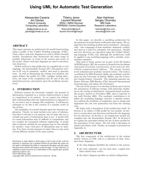
Using UML for Automatic Test Generation - IBM Research
Using UML for Automatic Test Generation - IBM Research
Using UML for Automatic Test Generation - IBM Research

You also want an ePaper? Increase the reach of your titles
YUMPU automatically turns print PDFs into web optimized ePapers that Google loves.
ABSTRACT<br />
<strong>Using</strong> <strong>UML</strong> <strong>for</strong> <strong>Automatic</strong> <strong>Test</strong> <strong>Generation</strong><br />
Alessandra Cavarra<br />
Jim Davies<br />
Ox<strong>for</strong>d University<br />
Computing Laboratory<br />
ale@comlab.ox.ac.uk,<br />
jdavies@comlab.ox.ac.uk<br />
This paper presents an architecture <strong>for</strong> model-based testing<br />
using a profile of the Unified Modeling Language (<strong>UML</strong>).<br />
Class, object, and state diagrams are used to define essential<br />
models: descriptions that characterise the entire range of<br />
possible behaviours, in terms of the actions and events of<br />
the model. Object and state diagrams are used to introduce<br />
test directives.<br />
Models written in this profile may be compiled into a tool<br />
language: the Intermediate Format (IF). Descriptions written<br />
in IF can be animated, verified, and used to generate<br />
tests. As well as illustrating the testing tool adopted, the<br />
paper defines the profile <strong>for</strong> <strong>UML</strong>, explains testing directives,<br />
the basis of the compilation into IF and of the test<br />
generation process, and reports upon the problems encountered.<br />
1. INTRODUCTION<br />
Software systems are extremely complex; the amount of<br />
in<strong>for</strong>mation contained in a system implementation is hard<br />
to comprehend in its entirety. As we cannot test without<br />
first understanding what the implementation is supposed to<br />
do, we need a way to manage this complexity. A well-known<br />
technique to do this is the creation of a suitable model of<br />
the system.<br />
The suitability of a model depends upon the intended application.<br />
Clearly, we must include every piece of in<strong>for</strong>mation<br />
that is relevant to our purpose, but we must also try to<br />
exclude any piece of in<strong>for</strong>mation that is not. A model with<br />
too much in<strong>for</strong>mation may be difficult to comprehend, and<br />
too complex <strong>for</strong> automated software engineering. A model<br />
that is entirely suitable <strong>for</strong> one purpose may be less suitable<br />
<strong>for</strong> another: some vital piece of in<strong>for</strong>mation may be missing.<br />
If we have several purposes in mind, then we may need<br />
several different models of the same system.<br />
Permission to make digital or hard copies of all or part of this work <strong>for</strong><br />
personal or classroom use is granted without fee provided that copies are<br />
not made or distributed <strong>for</strong> profit or commercial advantage and that copies<br />
bear this notice and the full citation on the first page. To copy otherwise, to<br />
republish, to post on servers or to redistribute to lists, requires prior specific<br />
permission and/or a fee.<br />
ISSTA 2002 Rome, Italy<br />
Copyright 2001 ACM X-XXXXX-XX-X/XX/XX ...$5.00.<br />
Thierry Jeron<br />
Laurent Mounier<br />
IRISA / INRIA Rennes/<br />
VERIMAG–Centre Equation<br />
thierry.jeron@irisa.fr,<br />
laurent.mounier@imag.fr<br />
Alan Hartman<br />
Sergey Olvovsky<br />
<strong>IBM</strong> Haifa<br />
<strong>Research</strong> Laboratory<br />
hartman@il.ibm.com,<br />
olvovsky@il.ibm.com<br />
In this paper, we describe a modelling architecture <strong>for</strong><br />
the purposes of model-based verification and testing. We explain<br />
how the resulting models can be translated—automatically—into<br />
a language of state machines, animated, verified,<br />
and used as a basis <strong>for</strong> automatic test generation. Models<br />
and test directives are described using the Unified Modeling<br />
Language (<strong>UML</strong>) [12], although the architecture could<br />
be applied to any modeling language with a suitable, statemachine<br />
semantics.<br />
This work is being carried out as part of the EU-funded<br />
AGEDIS project [20]; the acronym is <strong>for</strong>med from the phrase<br />
Automated <strong>Generation</strong> and Execution of test suites <strong>for</strong> DIstributed<br />
component-based Software. The project involves<br />
seven industrial and academic research centres. The work is<br />
coordinated by <strong>IBM</strong> <strong>Research</strong>, Haifa; the academic contributors<br />
are the University of Ox<strong>for</strong>d, IRISA, and the Université<br />
Joseph Fourier, Grenoble. The industrial partners are<br />
France Telecom, <strong>IBM</strong> Hursley (UK); Intrasoft International<br />
(Luxembourg); and imbus AG (Germany).<br />
The aim of the project is to develop methods and tools <strong>for</strong><br />
the automation of software testing, with particular emphasis<br />
on the testing of distributed, component-based systems;<br />
the project started in November 2000, and is expected to<br />
run until October 2003. The academic contribution is to<br />
define the modelling language, describe a suitable semantics,<br />
address the problems of complexity, and to design and<br />
implement the new test generation tool from the existing<br />
ones.<br />
We begin with a description of the architecture itself. In<br />
Section 3, we define a <strong>UML</strong> profile <strong>for</strong> test models. In Section<br />
4, we introduce test directives and describe the language<br />
<strong>for</strong> test directives. In Section 5, we explain how models are<br />
compiled into the Intermediate Format (IF). In Section 6<br />
we explain the principles behind the use of these models <strong>for</strong><br />
the generation of test suites. We end with a discussion of<br />
related and future work. Finally, an example is presented in<br />
Appendix A.<br />
2. ARCHITECTURE<br />
The first component of the architecture is the system<br />
model, written in <strong>UML</strong>; this is a collection of class, state,<br />
and object diagrams:<br />
• the class diagram identifies the entities in the system;<br />
• the state diagrams—one <strong>for</strong> each class—explain how<br />
these entities may evolve;<br />
• the object diagram specifies an initial configuration.
System model<br />
<strong>UML</strong><br />
class diagram<br />
object diagram<br />
state diagrams<br />
compile<br />
<strong>Test</strong> directives <strong>UML</strong> object diagrams state diagrams<br />
State machine<br />
IF<br />
generate /<br />
model-check<br />
<strong>Test</strong> suite / result<br />
ATS<br />
test<br />
System implementation<br />
Figure 1: An architecture <strong>for</strong> automatic test generation<br />
The second component, again written in <strong>UML</strong>, is the test<br />
directive; this consists of particular object and state diagrams:<br />
• the object diagrams are used to express test constraints<br />
and coverage criteria;<br />
• the state diagrams specify test purposes.<br />
The system model and the test directiv es can be constructed<br />
using any of the standard toolsets, such as Rational<br />
Rose [5], Together Control Center [22], or Objecteering [19].<br />
The compiler takes the model and produces a collection of<br />
extended interacting state machines, written in the Intermediate<br />
Format (IF) language [2]. The <strong>for</strong>m of each machine<br />
is dictated by the state diagrams of the model, their interaction<br />
mimics the action–event mechanism of <strong>UML</strong>.<br />
An IF representation can be animated, verified, or modelchecked<br />
using the tools of the CAESAR/ALDEBARAN Development<br />
Package (CADP) [9]. In this case, the test directive<br />
describes a test upon the model, a property to be<br />
checked, and the output is either a confirmation that the<br />
property holds, or an explanation of why it does not.<br />
Alternatively, an IF representation can be provided as input<br />
to the TGV (<strong>Test</strong> <strong>Generation</strong> with Verification) tool [18].<br />
In this case, the state diagram component of the test directive<br />
is used to guide the exploration of the underlying transition<br />
system, constructed—on-the-fly, if necessary—from the<br />
IF state machine description. The output of the test generation<br />
is an abstract test suite (ATS) containing the sequence<br />
of simulations and observations (with the associated verdict)<br />
a test engine should per<strong>for</strong>m to run the test against a system<br />
implementation. Several <strong>for</strong>mats are available to represent<br />
the ATS (<strong>for</strong> instance TTCN is one of the standard used in<br />
the telecommunication industry).<br />
3. THE AGEDIS MODELLING LANGUAGE<br />
In the sequel, we refer to the subset of <strong>UML</strong> that we have<br />
chosen as the AGEDIS Modelling Language (AML).<br />
3.1 Choosing <strong>UML</strong><br />
A primary consideration in choosing this language was<br />
accessibility, or ease of use. It must be within reach of the<br />
ordinary practitioner—modeller or tester—in the software<br />
industry. This led us to a graphical notation, based upon<br />
an existing, industry-standard modelling language: <strong>UML</strong><br />
was the best candidate.<br />
Another consideration was domain appropriateness, acombination<br />
of adequacy and abstraction. The chosen subset of<br />
<strong>UML</strong> must be rich enough to describe the properties that<br />
we wish to test. At the same time, it should not include<br />
any unnecessary constructs, complication, or complexity: it<br />
should be as simple as possible.<br />
Closely related is a consideration of compositionality, or<br />
scalability. It should be possible to combine models of components<br />
to produce a model of a complete system. The existing<br />
semantics of <strong>UML</strong> does not present enough in<strong>for</strong>mation<br />
to achieve this; we have extended it with an explanation of<br />
message passing and interaction.<br />
(Although the semantics has been extended, to produce a<br />
precise, complete interpretation of those parts of <strong>UML</strong> that<br />
we need, the syntax of the language has not: we are working<br />
entirely within the accepted <strong>UML</strong> syntax; the additional<br />
in<strong>for</strong>mation required can be supplied using standard <strong>UML</strong><br />
constructs and mechanisms.)<br />
The <strong>UML</strong> [12] is a set of techniques <strong>for</strong> specification,<br />
visualisation, and documentation. The language is based<br />
primarily upon object-oriented methodology; however, concepts<br />
were added from Harel’s language of StateCharts [13],<br />
Petri Nets, Message Sequence Charts and SDL.<br />
An important aspect of <strong>UML</strong> is the presence of variation<br />
points in the language semantics: the definition of the language<br />
is intentionally incomplete; further interpretation is<br />
requiredbe<strong>for</strong>eamodelwrittenin<strong>UML</strong>canbeusedasa<br />
basis <strong>for</strong> <strong>for</strong>mal analysis or automatic test generation.<br />
Also required is instantiation. <strong>UML</strong> does not include a<br />
language of data types and operations; instead, these are<br />
written in the target language of the specification, normally<br />
an imperative programming language. If we wish to compile<br />
our models, we must define a target language.<br />
3.2 Target language<br />
We will use IF itself as our target language. Operations,<br />
actions, and data types will all be written using a basic subset<br />
of IF syntax, accessible to anyone who has some familiarity<br />
with imperative programming languages. There are<br />
two obvious advantages to this choice:<br />
• our diagrams will use the same target language, whether<br />
the language of implementation is C, C++, or Java;<br />
• the compiler can focus upon the translation of state<br />
machines, and the interpretation of <strong>UML</strong> actions; it<br />
does not need to translate primitives.<br />
The translation from the implementation language of an<br />
API—whether it is C, C++, or Java—to this syntax is easily<br />
automated. The only aspect that invites user intervention<br />
is the choice of data representation.<br />
The primitive types defined <strong>for</strong> IF include the standard C<br />
datatypes, integers, arrays, and records. So user intervention<br />
is not required; however, it may be desirable.<br />
3.3 Class diagrams<br />
A class is a description of a set of objects that share the<br />
same attributes, operations, relationships, and semantics.<br />
In a class diagram, each class is drawn as a rectangle with<br />
three compartments: the top compartment holds the class<br />
name, the middle holds a list of attributes; the bottom holds<br />
a list of operations.<br />
In our profile, attributes may be observable: the values of<br />
observable attributes may be inspected at any point during
a test. By default, attributes are not observable: we indicate<br />
that they are by adding a tag.<br />
Operations may also be observable, in that the occurrence<br />
of the operation (and any return value) will be recorded in<br />
any projected model. Furthermore, they may be controllable,<br />
indicating that they may be called from outside the<br />
system—during a test; we may use another tag to indicate<br />
this.<br />
We use associations in place of data attributes of class<br />
type. In a class diagram, an association is represented as a<br />
solid line between classes. Associations may be annotated<br />
with roles—an attribute name at one end reveals the (<strong>for</strong>mal)<br />
name used <strong>for</strong> an object of the closer class, within the<br />
context of an object of the other class.<br />
3.4 Object diagrams<br />
An object diagram shows the state of the system at a<br />
certain point in time, as a collection of objects, each in a<br />
particular state. We will use object diagrams to describe<br />
the initial configuration of the system model, to specify a<br />
starting configuration in a test directive and to flag configurations<br />
<strong>for</strong> inclusion or exclusion in a test model.<br />
The object diagram notation is similar to the class notation.<br />
The state of an object may be constrained using an<br />
assertion, a state name from the corresponding state diagram,<br />
or by constraining the values of its attributes.<br />
The presence of a link between objects indicates that communication<br />
is possible. A link may be decorated with in<strong>for</strong>mation<br />
about roles: an attribute name at one end of a link<br />
reveals the name used, within the context of the closer object,<br />
<strong>for</strong> the object at the other end.<br />
We will annotate the object diagram representing the initial<br />
state of the system by the stereotype .<br />
3.5 State diagrams<br />
A state diagram shows how an object will react to the<br />
arrival of an event. Each reaction may be a sequence of actions,<br />
possibly accompanied by a transition from one named<br />
state to another. An event represents the receipt of a signal,<br />
or the effect of an operation call. An action represents the<br />
sending of a signal, or the call of an operation.<br />
To simplify the presentation, we may factor some of the<br />
transition in<strong>for</strong>mation into a state:<br />
• actions that are common to every incoming transition<br />
may be included as entry actions <strong>for</strong> that state;<br />
• actions that are common to every outgoing transition<br />
may be included as exit actions.<br />
If the only transition(s) that do not mention a particular<br />
action are self-transitions, then we may make these internal<br />
transitions, and proceed with the factorisation.<br />
A transition may be annotated with an event, a guard,<br />
and an action expression. The transition begins, or fires,<br />
with the occurrence of the trigger event. If there is a guard,<br />
it is evaluated be<strong>for</strong>e the action list is considered—should<br />
it prove to be false, no change in state will take place; in a<br />
sense, the transition is cancelled.<br />
If there is no guard, or if the guard is true, then the exit<br />
actions of the source state are per<strong>for</strong>med, followed by the<br />
actions of the transition itself, and then, finally, the entry<br />
actions of the target state.<br />
If two outgoing transitions are enabled at the same time—<br />
either because they are both labelled with the same event,<br />
initial state<br />
State 1<br />
entry / actionA<br />
exit / actionB<br />
event1 / actionC<br />
sequential<br />
composite<br />
state<br />
State 3<br />
event2 / actionD<br />
event3[guard] / actionG<br />
State 2<br />
entry / actionE<br />
exit / actionF<br />
event4<br />
event5<br />
Figure 2: A <strong>UML</strong> state diagram<br />
final state<br />
simple state<br />
or because neither requires an event, and both guards are<br />
true—then either may fire. State diagrams cope easily with<br />
the phenomenon of nondeterminism.<br />
3.6 Actions<br />
A call action is an action in which a stimulus—a call<br />
event—is created that can trigger an action sequence in another<br />
object. Call actions are synchronous: the caller waits<br />
<strong>for</strong> the event to be processed be<strong>for</strong>e resuming execution. A<br />
call action may have a return value.<br />
A send action also creates a stimulus—this time, a signal<br />
event. Send actions are asynchronous: the caller proceeds<br />
without waiting <strong>for</strong> the event to be processed. An object can<br />
send a signal event to any object <strong>for</strong> which it has a reference,<br />
including itself. A send action has no return value.<br />
Send actions need not correspond to operations in the receiving<br />
object. This means that we require a class diagram<br />
to explain the structure of signal events (the structure of a<br />
call event is already described by the signature of the corresponding<br />
operation, given in the main class diagram).<br />
In this class diagram, we may include a tag in each name<br />
compartment to indicate whether these events are observable<br />
or controllable—can be sent by the environment. To indicate<br />
that these are classes of signal events, we label each class<br />
with the stereotype .<br />
Both send and call actions begin with the name of the<br />
target object, which must be within the scope of the state<br />
diagram. It could be one of the declared attribute names,<br />
but it is more likely to be a role name, at the far end of a<br />
link or association.<br />
In the case of an object diagram, the role name is not<br />
needed to identify the callee object unless the object has<br />
been left anonymous, or is known by a different name inside<br />
the state diagram of the current object. Role names are<br />
not needed in class diagrams unless the object per<strong>for</strong>ming a<br />
particular role can be created during the test phase—in this<br />
case, it can’t be named in the initial object diagram.<br />
4. TEST DIRECTIVES<br />
We use the term “test directive” to denote the collection<br />
of in<strong>for</strong>mation that, when combined with the system model,<br />
defines the test suite that will be generated.<br />
<strong>Test</strong> directives are a <strong>for</strong>mal expression of some testing<br />
requirements. They are crucial in an automated test generation<br />
process since they allow the user to guide the test<br />
generator during the test selection phase. There<strong>for</strong>e they<br />
should offer a sufficient level of expressiveness (which model<br />
elements we can refer to, which primitives are allowed to<br />
describe the test requirements, etc).<br />
We propose here three kinds of test directives: test pur-
poses, test constraints and coverage criteria. In general, test<br />
directives provided by the user will come in <strong>for</strong>m of combinations<br />
of test purposes, test constraints, and coverage criteria.<br />
4.1 <strong>Test</strong> constraints<br />
<strong>Test</strong> constrains are used to describe additional restrictions,<br />
steering the test generator during the selection of relevant<br />
execution sequences. <strong>Test</strong> constraints may be described<br />
by object diagrams or included in a test purpose diagram<br />
(see section 4.3).<br />
Whereas in a test purpose diagram constraints are specified<br />
explicitly by boolean expressions, when an object diagram<br />
is used constraints are given by the system configuration<br />
the diagram represents.<br />
We propose four kinds of test constraints:<br />
• start to give a global constraint on the start state of<br />
the expected test case. The test case starts in a state<br />
S where the configuration given by the diagram holds.<br />
• include to express that at least one state of the sequences<br />
of the specification selected <strong>for</strong> test generation<br />
must satisfy the constraint given by the object<br />
diagram;<br />
• exclude to express that no state of the sequences of the<br />
specification selected <strong>for</strong> test generation should satisfy<br />
the the constraint given by the object diagram;<br />
• end to give a global constraint on the termination state<br />
of the expected test case.<br />
Accordingly, we stereotype object diagrams modelling test<br />
constraints , , , .<br />
4.2 Coverage criteria<br />
Coverage criteria describe coverage requirements when generating<br />
sets of test cases. They are used to generate a set<br />
of test cases with respect to a given coverage constraint. A<br />
coverage criterion is expressed as a set of expressions over<br />
object variables. For each reachable combination of these<br />
expression values, a test case is generated in which at least<br />
one state of the selected sequences satisfies the given constraint.<br />
This coverage can there<strong>for</strong>e be viewed as a set of<br />
include constraints, producing multiple test cases satisfying<br />
all the include predicates. In addition, projection coverage<br />
criteria statement may appear inside test purpose specifications.<br />
We adopt projected state and transition coverage<br />
criteria as described in [7].<br />
4.3 <strong>Test</strong> purposes<br />
A test purpose is a description of a pattern of behaviour.<br />
As with the patterns of behaviour in the model itself, it can<br />
be expressed as a <strong>UML</strong> state diagram. The main differences<br />
are:<br />
• The test purpose is a description of system behaviour,<br />
so we have events and actions from different classes<br />
appearing in the same state diagram.<br />
• <strong>Test</strong> purposes can include global constraints, observations,<br />
coverage criteria, and global preamble and<br />
postamble constraints.<br />
• The trigger and action expressions that decorate transitions<br />
can include regular expressions. They do not<br />
represent processing of events by the local machine;<br />
they match transitions of the model. Transition may<br />
also have local coverage in<strong>for</strong>mation.<br />
• In order to provide additional in<strong>for</strong>mation <strong>for</strong> the test<br />
generator, states may have special labels and be annotated<br />
by local constraints, observation, and coverage<br />
criteria.<br />
We will label any state diagram that <strong>for</strong>ms part of a test<br />
directive with the stereotype (there is<br />
no need to stereotype the state diagrams used to define the<br />
system model).<br />
Combining test directives. <strong>Test</strong> purposes may be combined<br />
to test constraints and coverage criteria both globally<br />
(at the diagram level) and locally (at the state/transition<br />
level).<br />
Globally, such combinations are shown by means of notes<br />
attached to the test purposes diagram. In particular, a test<br />
purpose can be annotated with a note containing the following<br />
in<strong>for</strong>mation<br />
• start/ bool-expression defines the beginning of a<br />
test cases: the test case starts in a state S where the<br />
given boolean expression holds. The part of test case<br />
leading from the initial state to state S is called preamble.<br />
• include/ bool-expr_1...bool-expr_n to impose that<br />
at least one state of the sequences of the specification<br />
selected <strong>for</strong> test generation must satisfy the given constraints.<br />
• exclude/ bool-expr_1...bool-expr_n expresses that<br />
no state of the sequences of the specification selected<br />
<strong>for</strong> test generation should satisfy the given constraints.<br />
• end/ bool-expression defines the end of a test case,<br />
i.e. the test case ends in a state S where the given<br />
boolean expression holds. The sequence leading from<br />
the state where the verdict has been established to<br />
state S is called postamble.<br />
• cover/ expr_1,..expr_n ["when" bool-expression]<br />
selects test cases containing all the reachable combinations<br />
of expressions expr_1,..expr_n provided that<br />
bool-expression is satisfied.<br />
States. States are part of the functional test purpose. Each<br />
state may be annotated by local constraints, observation,<br />
and coverage criteria, according to the following syntax:<br />
exclude/ bool-expr_1, ...bool-expr_n<br />
observe/ var1, ...varn ["when" bool-expression]<br />
cover/ expr_1, ...expr_n ["when" bool-expression]<br />
We use the following reserved labels to indicate some special<br />
states:<br />
• #init simply indicates the test purpose initial state;<br />
• #accept indicates a successful termination of the test,<br />
i.e. the termination of test sequences one wants to<br />
include in the test selection;
• #reject indicates a rejecting state, it allows to exclude<br />
some behaviours from the test selection;<br />
• #start to indicate the initial state of the actual test<br />
case;<br />
• #end denotes the test purpose final state.<br />
exclude/bool-expr_1...<br />
bool-expr_n<br />
observe/ var1...varn w hen bool-expr<br />
cover / expr_1...expr_n whenbool-expr<br />
State<br />
Triggers and guards. The generation tool will explore a<br />
combination of the model and the test purpose. In this combination,<br />
a transition occurs <strong>for</strong> the test purpose whenever<br />
a matching transition occurs <strong>for</strong> the model.<br />
transition-label ::= trigger ["["guard"]"]<br />
guard ::= bool-expression |<br />
"cover" expr_1, ...expr_n<br />
["when" bool-expression]<br />
trigger ::= "otherwise" |<br />
regular-expression-on-model-events<br />
Regular expression labels are supposed to match with<br />
specification transition labels. During test generation, specification<br />
and test purpose are strongly synchronised. A transition<br />
of the test purpose is required to match a transition of<br />
the specification. The otherwise label denotes a transition<br />
that is to be fired if in the test purpose there is no transition<br />
synchronising with the specification.<br />
We indicate that an event is to be received by a component’s<br />
state machine by prefixing the event with a question<br />
mark (?); e.g. ?obj.ev() means that event ev must be received<br />
by obj. To express that an event is to be sent to a<br />
component, we prefix the event with an exclamation mark<br />
(!); e.g. !obj.ev() means that event ev must be sent to obj.<br />
To express that an object obj1 calls an operation of another<br />
object, say obj2, arising an event we write obj1!obj2.op().<br />
Finally, to express that an object obj2 receives an operation<br />
call from another object obj1, wewriteobj1?obj2.op().<br />
Parameters of input/output events can be either explicit<br />
values, or wild cards. In particular, we use "*" to indicate<br />
an arbitrary number of elements and "_" to indicate exactly<br />
one element. Regular expressions are expressed according<br />
to the following notation.<br />
• An event can be preceded and followed by any other<br />
event, or alternatively by a particular one (in this latter<br />
case we need to match a sequence of events). We<br />
write *{a,b,c} to indicate that events a, b, andc must<br />
occur, but any other event can also occur.<br />
• All or some of the parameters of a given event are<br />
irrelevant. We write ev(_,x,_) to indicate that the<br />
first and third parameters are irrelevant, whereas the<br />
second one must be x. Wewriteev(*) to indicate that<br />
the event’s parameter can have any value.<br />
• The object instance per<strong>for</strong>ming a given operation is irrelevant.<br />
We specify this as *className3.operation().<br />
State1<br />
State2<br />
State3<br />
#accept<br />
!obj1.A(_,obj1.x)<br />
?obj1.B(_,_,_)[obj1.x > obj2.y]<br />
obj2!obj3.C(_)[obj3.z and obj3.w]<br />
Figure 3: A test purpose<br />
For instance, the test purpose in fig. 3 generates test cases<br />
by selecting execution sequences in the system model as<br />
follows: after an arbitrary number of transitions not per<strong>for</strong>ming<br />
“!obj1.A(_,obj1.x)”, the action occurs in a transition<br />
(the first parameter being any value). Then, again<br />
after an arbitrary number of transitions not labelled with<br />
“?obj2.B(_,_,_)”, we reach a state in which the condition<br />
“obj1.x > obj2.y” holds, and from which the event<br />
“?obj2.B(_,_,_)” is received (<strong>for</strong> any parameter values).<br />
Finally, last transition in the test purpose fires if the condition<br />
“obj3.z and obj3.w” holds and in the system specification<br />
obj2 calls method C (with any parameter value) of<br />
object obj3.<br />
Guards are boolean expressions over objects attributes.<br />
They are specified using IF enriched with (universal and<br />
existential) quantifiers over system objects.<br />
5. COMPILATION<br />
The Intermediate Format (IF) language was developed<br />
to sit between high-level specification languages, such as<br />
Sdl [15], Promela [14] or Lotos [4], and tool-specific internal<br />
representations. IF representations can be passed between<br />
tools, and translated into other languages: <strong>for</strong> example,<br />
Sdl specifications can be analysed using the Spin<br />
model-checker [14]. Moreover, translating high-level languages<br />
into IF may also allow to extend (or fix) some (open)<br />
parts of their semantics: <strong>for</strong> example IF is used to give a<br />
precise timed semantics to Sdl [3].<br />
The choice of using IF as an intermediate <strong>for</strong>mat between<br />
the AML modelling language and the test generation tool is<br />
motivated by several arguments:<br />
• First of all, it allows us to re-use some of the tools<br />
already developed within the IF environment. In particular<br />
the existing IF simulation engine, abletogenerate<br />
on-the-fly the underlying labelled transition systems<br />
associated to an IF description, will be used as a<br />
front-end of the test generation tool.<br />
• Moreover, using IF offers a relative flexibility when<br />
defining the AML semantics: <strong>for</strong> a given AML con-
struct, several translation schemes can be <strong>for</strong>eseen, independently<br />
of the simulation engine. Thus, it becomes<br />
easy to define the AML semantics in an incremental<br />
way, and to extend the compiler accordingly.<br />
• Finally, the potential loss of efficiency caused by the<br />
use of an intermediate representation (instead of per<strong>for</strong>ming<br />
the simulation directly at the AML level) is<br />
largely compensated by the optimisation tools available<br />
at the IF level. In fact, previous experience with<br />
Sdl demonstrated that using IF and static analysis<br />
techniques gave us a much more efficient simulator<br />
than the already existing ones. In particular modelbased<br />
test generation can be advantageously combined<br />
with slicing techniques[1]<br />
In IF, each of the objects in our specification is represented<br />
as an extended finite state machine, or process instance. The<br />
state of each process—the values of local variables—is private;<br />
processes evolve and communicate by sending and receiving<br />
asynchronous signals along specified signalroute instances.<br />
Process and signalroute instances can be either<br />
created statically (at system initialisation), or dynamically<br />
(at run-time). A signalroute can be reliable or lossy, peerto-peer<br />
or multicast, FIFO or multiset, timely or delayed.<br />
As in <strong>UML</strong>, the arrival of a signal may trigger a transition<br />
between states, accompanied by a specified sequence of<br />
actions. This sequence may involve sending signals to other<br />
processes, or changing the values of local variables.<br />
The process of compilation revolves around the state diagrams<br />
of our model; each of these will be trans<strong>for</strong>med into<br />
an IF process. The initial (or start) object diagram <strong>for</strong> the<br />
model (or test directive) defines the initial configuration of<br />
processes. The class diagram provides in<strong>for</strong>mation about<br />
data types and operations.<br />
The translation into IF defines an effective semantics <strong>for</strong><br />
the <strong>UML</strong> language of state diagrams. We need to define:<br />
• an IF signal <strong>for</strong> each operation;<br />
• an acknowledgment signal, including a return value<br />
parameter, <strong>for</strong> each synchronous operation (since communications<br />
are always asynchronous in IF);<br />
• a process <strong>for</strong> each object in the model;<br />
• a communication buffer <strong>for</strong> each object.<br />
5.1 States<br />
Each state in a state diagram is translated into an IF<br />
control state, with stability and initiality attributes. If a<br />
state is marked as unstable, then any transaction through<br />
this state—a transition to, and a transition from—is treated<br />
as atomic, across the system. If a state is marked as initial,<br />
then it is treated as an initial state of the process.<br />
A start state in a state diagram becomes an :init state<br />
in IF; a finish state becomes a state with no transitions.<br />
To translate a simple state, we append the entry actions<br />
to every incoming transition; prepend the exit actions to<br />
every outgoing transition; trans<strong>for</strong>m any internal transition<br />
into an external, self transition, but without entry or exit<br />
actions.<br />
5.2 Transitions<br />
Having mapped the object states into IF, we can construct<br />
a transition in IF <strong>for</strong> each transition in the state diagram:<br />
from currentState<br />
input operationName from thisBuffer<br />
if guard<br />
do action ;<br />
[ output ack(returnValue) to callerBuffer ]<br />
to newState<br />
The output clause is used only in response to synchronous<br />
operations, modeled as call actions.<br />
5.3 Events<br />
A call event represents an operation invocation in which<br />
the caller will be notified of completion, and provided with<br />
any return value. We translate call events into IF signal<br />
inputs:<br />
input operation-name (reference-list)<br />
from buffer<br />
where operation-name is an operation of the current object;<br />
reference-list is a list of variables in which the received<br />
parameters are stored, buffer the name of the buffer from<br />
which the event will be read.<br />
To achieve synchronisation with the caller object, we add<br />
a symmetrical action after every signal input representing<br />
a call event, sending an appropriate completion or return<br />
signal to the caller.<br />
A signal event represents the reception of a <strong>UML</strong> signal—<br />
used to model asynchronous communication. We translate<br />
signal events directly into IF signal inputs:<br />
input signal (reference-list)<br />
from buffer<br />
but this time there is no matching acknowledgement action.<br />
5.4 Guards<br />
These are translated into post guarded inputs where the<br />
received parameters can be tested; this guard is evaluated<br />
if the input is received and, if false, the execution of the<br />
transition is disabled, restricting the values that the process<br />
is willing to accept. In our modeling language, guards will<br />
be expressed by IF expressions.<br />
5.5 Actions<br />
To translate a call action, we must add an additional,<br />
stable state to the IF representation of the object. This is<br />
the state in which the object has issued the call, but the<br />
operation has yet to return. If the state diagram has a<br />
transition from State1 toState2, labelled with call action<br />
a, thenweobtainanIFrepresentationofthe<strong>for</strong>m<br />
from State1<br />
input event from callerBuffer<br />
if guard<br />
do action ;<br />
to StateX<br />
from StateX<br />
input ack_a from calleeBuffer<br />
to State2<br />
Each send action becomes an IF output:<br />
output signal(parameters) to targetBuffer<br />
This has the effect of appending the specified signal to the<br />
buffer associated with the target object.
6. TEST GENERATION<br />
The AGEDIS test generation tool is based on the principles<br />
of two existing tools TGV [17] and GOTCHA-TCBeans [7].<br />
These tools have different principles, summarised below; we<br />
describe how these principles are adapted and combined in<br />
the AGEDIS test generation tool.<br />
6.1 TGV<br />
TGV is a test generation tool developed by Verimag and<br />
Irisa [17] and based on a sound testing theory [23]. The<br />
theory and test generation algorithms ensure that no con<strong>for</strong>mant<br />
implementation can be rejected by a test case and<br />
that it is theoretically possible to generate a test case that<br />
can reject any non-con<strong>for</strong>mant implementation. Models of<br />
specifications are IOLTS (Input Output Labelled Transition<br />
Systems) produced by simulation, where inputs, outputs and<br />
internal events are distinguished. The behaviour of the implementation<br />
under test is unknown (black box) but we suppose<br />
that it can be modelled by an IOLTS. A con<strong>for</strong>mance<br />
relation ioco defines the correct implementations I with respect<br />
to a given specification S. To allow the detection of<br />
incorrect quiescence of I (by timers in test cases), ioco is<br />
defined in terms of traces of the suspension automata δ(I)<br />
and δ(S). δ(S) is built from S by the addition of loops<br />
labelled by a new output δ in each quiescent state, i.e. a<br />
livelock, a deadlock, or an absence of output. Now, IiocoS<br />
if after every trace of δ(S) (including δ), the outputs of I<br />
are included in those of S.<br />
The two main inputs of TGV are the IOLTS of the specification<br />
S and a test purpose TP used <strong>for</strong> test selection.<br />
TP is a complete automaton with Accept and Reject states.<br />
Accept states are used to select behaviours of S one wants<br />
to test, while Reject states may prune the exploration of<br />
S. LabelsofTP are regular expressions matching S’s labels<br />
and a particular label ∗ meaning “otherwise”.<br />
The test generation process is composed of three operations.<br />
A product S × TP which synchronises on common<br />
actions is used to mark states of S with Accept and<br />
Reject states of TP. This operation may also unfold S.<br />
The second operation computes the suspension automaton<br />
δ(S × TP) and determinises it while propagating the marking<br />
on state sets. The result is a deterministic IOLTS SPvis,<br />
with same observable traces as δ(S) and where Accept and<br />
Reject states mark behaviours accepted or rejected by TP.<br />
A selection operation then builds two possible objects: a<br />
complete test graph CTG consisting of all traces leading to<br />
accept (to which a Pass verdict is associated), plus divergences<br />
on these traces by outputs of S (giving rise to an<br />
Inconclusive verdict); alternatively a test case TC (a subgraph<br />
of CTG) is obtained by the additional constraint that<br />
test cases never have controlability conflicts, i.e. choices between<br />
an output and another action. In both cases, in any<br />
state of CTG or TC where an output of S is observable,<br />
Fail verdicts are implicit on all unspecified outputs. Finally<br />
a mirror image of CTG and TC is applied which inverts<br />
inputs and outputs.<br />
To our knowledge, TGV is the only test generation tool<br />
that can generate test cases with loops, while others are<br />
restricted to sequences or trees. TGV also accepts optional<br />
files which define the test architecture. A rename file is used<br />
to rename labels of S, a hide file specifies unobservable actions<br />
of S, and an IO file distinguishes inputs from outputs<br />
among observable actions. All three files support regular ex-<br />
pressions. Some additional options may be used to tune the<br />
test generation process: exploration depth, computation of<br />
postambles, priorities on the order of exploration of transitions,<br />
synthesis of timer operations (start, cancel, timeout).<br />
In order to avoid state explosion, the specification S can<br />
be given implicitly by a simulation API (functions <strong>for</strong> S’s<br />
traversal). In this case, the test generation operations are<br />
not applied in sequence but on-the-fly (except <strong>for</strong> some cases<br />
of conflict resolution) and only the necessary parts of S, of<br />
S × TP and of PSvis are built.<br />
Consequently, TGV can be used <strong>for</strong> different specification<br />
languages, as soon as a simulation API can be produced by a<br />
compiler of this language. This has been done <strong>for</strong> SDL with<br />
ObjectGeode (Telelogic), Lotos with the CAESAR compiler<br />
(Inria Grenoble), <strong>UML</strong> with the Umlaut tool and IF with<br />
the IF2C compiler. TGV also accepts specifications in the<br />
<strong>for</strong>m of explicit graphs in the BCG and Aldebaran <strong>for</strong>mats.<br />
<strong>Test</strong> cases are produced in BCG or Aldebaran <strong>for</strong>mat, and<br />
in pseudo-TTCN <strong>for</strong> SDL specifications.<br />
6.2 GOTCHA<br />
GOTCHA is a test generation tool developed by the <strong>IBM</strong><br />
<strong>Research</strong> Laboratory in Haifa. It is an extension of the Murφ<br />
model checker. The main differences with TGV are the following:<br />
The specification model describes the observable<br />
behaviour of the system, not its internal behaviour. The<br />
model is a finite state machine with edges labelled with inputsandstateslabelledwithbothacontrolstateandthe<br />
values of observable variables.<br />
The test generation process is based on a traversal of the<br />
finite state machine directed by coverage criteria and test<br />
constraints. Coverage criteria are based on an abstract state<br />
space defined by expressions on subsets of variables and control<br />
states. This abstract state graph is conceptual and not<br />
built explicitly. A state coverage criterion is a boolean expression<br />
on an abstract state while a transition coverage<br />
criterion is a pair of boolean expressions on the source and<br />
target states of an abstract transition. Both criteria are<br />
trans<strong>for</strong>med into a finite set of coverage tasks that instantiate<br />
the conditions. The first phase of test generation determines<br />
which of the specified coverage tasks are reachable,<br />
and chooses a random representative of each reachable task.<br />
The test generation engine then covers each of these tasks<br />
by a set of paths in the specification.<br />
<strong>Test</strong> constraints may be used to restrict test sequences<br />
and limit the reachable set of states and transitions in the<br />
finite state machine. It is possible to <strong>for</strong>bid the traversal<br />
of a state which satisfies a condition or to <strong>for</strong>bid certain<br />
paths which satisfy boolean conditions on their beginning,<br />
middle, end, and length. Several traversal strategies can be<br />
used, including on-the-fly and coverage directed traversal.<br />
<strong>Test</strong> cases computed by GOTCHA are sequences composed<br />
of actions and expected values of observable variables. Nondeterministic<br />
transitions in a test case are dealt with by the<br />
use of an ”inconclusive” outcome, as well as the ”pass” and<br />
”fail” outcomes <strong>for</strong> a test case.<br />
6.3 Principles of the AGEDIS test generation<br />
tool<br />
In the AGEDIS project, we are developing a test generation<br />
engine which combines the principles of TGV and<br />
GOTCHA, namely test selection using test purposes, test<br />
constraints, and coverage criteria. <strong>Test</strong> cases allow a com-
ination of observations: outputs as in TGV, but also values<br />
of variables defined as observable at the AML level as<br />
in GOTCHA. The input of the test generation process is<br />
an IF model, obtained by translation from an AML model.<br />
This model contains the specification of the system, test<br />
directives and the test architecture. Additionally, a mapping<br />
between AML and IF objects is generated, allowing<br />
the description of test cases in terms of AML objects. The<br />
test architecture consists of a list of controllable signals and<br />
calls and a list of observable signals, calls and variables corresponding<br />
to the IO and hide files of TGV. In the sequel,<br />
we focus on the different test directives and how they are<br />
used <strong>for</strong> test generation.<br />
6.3.1 <strong>Test</strong> generation<br />
The test generation engine will be mostly based on TGV,<br />
but it has to be extended in several ways to cope with test<br />
directives.<br />
Since test directives refer to specification variables and<br />
control states in boolean predicates or guards, they must be<br />
compiled and linked with the IF specification of the system<br />
into a simulation API. The simulation API used by the test<br />
generation engine consists of functions <strong>for</strong> the construction<br />
and observation of the product between the specification and<br />
test directives.<br />
The product between the specification and test purpose<br />
is different from TGV. In order to avoid unnecessary intermediate<br />
states, a transition of the specification may consist<br />
of an atomic sequence of actions, possibly starting with an<br />
input, and followed by outputs and/or internal actions. As<br />
a transition of a test purpose contains only one action (observable<br />
or not), this transition matches a transition of the<br />
specification which contains this event. Hiding according to<br />
the test architecture, is also treated differently as we have<br />
to hide some actions in a transition, but not necessarily all<br />
actions.<br />
In TGV, S and S × TP are IOLTS where states are just<br />
identifiers. In AGEDIS, values of variables may be observable,<br />
so states of S and S × TP carry a vector of values of<br />
observable variables. After determinisation, as a state is a<br />
set of states, it carries a set of vectors of values which defines<br />
the set of correct observations of the observable variables.<br />
This set is attached to the corresponding state of the test<br />
case, if this one is selected. All other observations lead to a<br />
fail verdict.<br />
The test selection process incorporates TGV and GOTCHA<br />
mechanisms. For each test purpose it builds one test case (or<br />
the complete test graph), also satisfying the test constraints.<br />
In the case of a coverage criteria, it builds a set of test cases<br />
or a test graph covering all reachable coverage tasks. To<br />
avoid redundancy in the computation, all test purposes and<br />
coverage criteria can be processed together. Breadth first<br />
and depth first traversal strategies, both on-the-fly, are possible.<br />
7. DISCUSSION<br />
The work described here is still in progress. An architecture<br />
has been defined, and the AML to IF compiler is being<br />
written. Moreover, some modelling with AML is currently<br />
being done by our industrial partners.<br />
7.1 Conclusion and related work<br />
The prospect of some degree of automation in the testing<br />
process is clearly an attractive one. Computing is becoming<br />
more pervasive, and more critical to our lives; at the same<br />
time, designs are becoming more complex, and interactions<br />
between components are becoming harder to measure and<br />
predict. Software testing is becoming more difficult, and<br />
more expensive.<br />
A considerable amount of research has been carried out<br />
into the application of Finite State Machine (FSM) notations<br />
to testing, and test generation, particularly with regard<br />
to the testing of communicating systems [10]. This<br />
research solves fundamental problems in testing, but does<br />
not attempt to address the problems of scale and complexity<br />
encountered in modern software engineering.<br />
Other research, from theories of testing <strong>for</strong> StateCharts [13]<br />
and methods <strong>for</strong> behavioural model generation [6], through<br />
to toolkits <strong>for</strong> automated testing [11], and packages <strong>for</strong> generating<br />
input sequences <strong>for</strong> testing user interfaces [21], has<br />
taken a more pragmatic, industrial approach. Of these,<br />
only one [11] presents an architecture: a precursor to that<br />
adopted <strong>for</strong> the AGEDIS project.<br />
There already exist tools <strong>for</strong> the generation of test cases<br />
from <strong>UML</strong> models. Umlaut/TGV [16] is such a tool: Umlaut<br />
provides a simulation API used by TGV <strong>for</strong> test generation<br />
This tool suffers from limitations in the considered<br />
<strong>UML</strong> subset and TGV limitations in the expression of test<br />
directives.<br />
The main advantage of the AGEDIS test generation tool<br />
is its ability to combine different test directives: coverage<br />
criteria, test purposes and test constraints. This allows the<br />
user to tune the selection of test cases with respect to the<br />
budget of the test campaign. Moreover, a hierarchy of test<br />
suites can be constructed with the property that the larger<br />
the test suite, the greater the coverage of the implementation.<br />
This hierarchy is particularly useful in regression<br />
testing. <strong>Test</strong>Composer (Telelogic) already combines coverage<br />
and test purposes <strong>for</strong> SDL but coverage is limited to<br />
branch coverage.<br />
There are several reports of success in automated test case<br />
generation. One of the examples [8] includes the comment:<br />
However, questions remained about the scalability<br />
of the approach ... A state-machine based approach<br />
... would perhaps be more appropriate in<br />
such circumstances.<br />
The focus of our research is exactly this: we are working<br />
towards scalable methods <strong>for</strong> automated test generation, using<br />
object-oriented principles, and building on fundamental<br />
research from the world of finite state machines.<br />
Acknowledgements<br />
The authors wish to acknowledge Marius Bozga and Charles<br />
Crichton <strong>for</strong> their helpful comments and contribution.<br />
8. REFERENCES<br />
[1] M. Bozga, J.Cl. Fernandez, and L. Ghirvu. <strong>Using</strong><br />
Static Analysis to Improve <strong>Automatic</strong> <strong>Test</strong><br />
<strong>Generation</strong>. In S. Graf and M. Schwartzbach, editors,<br />
Proceedings of TACAS’00 (Berlin, Germany), LNCS,<br />
pages 235–250. Springer, March 2000.<br />
[2] M. Bozga, J.Cl. Fernandez, L. Ghirvu, S. Graf, J.P.<br />
Krimm, and L. Mounier. IF: An Intermediate<br />
Representation and Validation Environment <strong>for</strong>
Timed Asynchronous Systems. In J.M. Wing,<br />
J. Woodcock, and J. Davies, editors, Proceedings of<br />
FM’99 (Toulouse, France), volume 1708 of LNCS,<br />
pages 307–327. Springer, September 1999.<br />
[3] M. Bozga, S. Graf, L. Mounier, I. Ober, J.L. Roux,<br />
and D. Vincent. Timed Extensions <strong>for</strong> SDL. In<br />
Proceedings of SDL FORUM’01, LNCS, 2001. to<br />
appear.<br />
[4] Ed Brinksma and Tommaso Bolognesi. Introduction<br />
to the ISO specification language LOTOS. Computer<br />
Networks and ISDN Systems, 14(1), 1987.<br />
[5] Rational Software Corporation. Rational rose. June<br />
2001, ”http://www.rational.com”.<br />
[6] Ibrahim Khalil Ibrahim El-Far. Automated<br />
construction of software behavior models. Master’s<br />
thesis, American University of Beirut, 1995.<br />
[7] E. Farchi, A. Hartman, and S. Pinter. <strong>Using</strong> a<br />
model-based test generator to test <strong>for</strong> standard<br />
con<strong>for</strong>mance. <strong>IBM</strong> System Journal - special issue on<br />
Software <strong>Test</strong>ing, 41(1):89–110, 2002.<br />
http://www.research.ibm.com/journal/sj41-1.thml.<br />
[8] M. S. Feather and B. Smith. <strong>Automatic</strong> generation of<br />
test oracles—from pilot studies to application.<br />
Automated Software Engineering, 8(1):31–61, January<br />
2001.<br />
[9] J. Fernandez, H. Garavel, A. Kerbrat, R. Mateescu,<br />
L. Mounier, and M. Sighireanu. CADP: A protocol<br />
validation and verification toolbox, 1996.<br />
[10] B. Gregor and V. Petrenko. Protocol testing: review<br />
of methods and relevance <strong>for</strong> software testing, 1994.<br />
[11] I. Gronau, A. Hartman, A. Kirshin, K. Nagin, and<br />
S. Olvovsky. A methodology and architecture <strong>for</strong><br />
automated software testing.<br />
http://www.haifa.il.ibm.com/projects/verification/<br />
gtcb/papers/gtcbmanda.pdf, 2000.<br />
[12] Object Management Group. Unified Modeling<br />
Language (<strong>UML</strong>) 1.4 draft, February 2001.<br />
http://www.omg.org/cgi-bin/doc?ad/2001-02-13.<br />
[13] David Harel and Eran Gery. Executable object<br />
modeling with statecharts. In Proceedings of<br />
the 18th International Conference on Software<br />
Engineering, pages 246–257. IEEE Computer Society<br />
Press, 1996.<br />
citeseer.nj.nec.com/article/harel97executable.html.<br />
[14] Gerard J. Holzmann. The model checker SPIN. IEEE<br />
Transactions on Software Engineering, 23(5):279–295,<br />
May 1997.<br />
[15] ITU-T. Recommendation Z.100. Specification and<br />
Description Language (SDL). Technical Report Z-100,<br />
International Telecommunication Union –<br />
Standardization Sector, Genève, November 1999.<br />
[16] T. Jéron, J.-M. Jézéquel, and A. Le Guennec.<br />
Validation and test generation <strong>for</strong> object-oriented<br />
distributed software. In IEEE Proc. Parallel and<br />
Distributed Software Engineering, PDSE’98, Kyoto,<br />
Japan, April 1998.<br />
[17] T. Jéron and P. Morel. <strong>Test</strong> generation derived from<br />
model-checking. In Nicolas Halbwachs and Doron<br />
Peled, editors, CAV’99, Trento, Italy, volume 1633 of<br />
LNCS, pages 108–122. Springer-Verlag, July 1999.<br />
[18] D. Lee and M. Yannakakis. Principles and Methods of<br />
<strong>Test</strong>ing Finite State Machines - A Survey. Proceedings<br />
of the IEEE, 84(8):1090–1123, August 1996.<br />
[19] <strong>UML</strong> Modeler. Objecteering.<br />
”http://www.softeam.fr/us/produits.htm”.<br />
[20] The AGEDIS project, 2000. ”http://www.agedis.de”.<br />
[21] S. Rosaria and Microsoft Corporation H. Robinson,<br />
Intelligent Search <strong>Test</strong> Group. Applying models in<br />
your testing process. In<strong>for</strong>mation and Software<br />
Technology, 42:815–824, 2000.<br />
[22] TogetherSoft. Together control centre. June 2001,<br />
”http://www.togethersoft.com”.<br />
[23] J. Tretmans. <strong>Test</strong> generation with inputs, outputs and<br />
repetitive quiescence. Software—Concepts and Tools,<br />
17(3):103–120, 1996.<br />
APPENDIX<br />
A. EXAMPLE<br />
In this example, we consider the alternating bit protocol, a<br />
simple yet effective protocol <strong>for</strong> managing the retransmission<br />
of lost messages. Consider a transmitter and a receiver,<br />
and assume that their communication channel is lossy. The<br />
alternating bit protocol works as follows.<br />
Each data message sent by the transmitter contains a<br />
protocol bit, False or True. Thetransmitter receives this<br />
message from its environment.<br />
When the transmitter sends a message <strong>for</strong> the first time,<br />
the number of transmission attempts is set to zero. Then, it<br />
sends it repeatedly (with its corresponding bit), each time<br />
incrementing the number of attempts made and reporting<br />
to its environment the number of attempts made, until receiving<br />
an acknowledgment (Ack) fromthereceiver that<br />
contains the same protocol bit as the message being sent.<br />
When the receiver receives a message, it sends an Ack to<br />
the transmitter and includes the protocol bit of the message<br />
received. The first time the message is received, the<br />
protocol delivers the message <strong>for</strong> processing. Subsequent<br />
messages with the same bit are simply acknowledged.<br />
When the transmitter receives an acknowledgment containing<br />
the same bit as the message it is currently transmitting,<br />
it stops transmitting that message, flips the protocol<br />
bit, and repeats the protocol <strong>for</strong> the next message.<br />
In the following, we show the AML specification of the<br />
protocol and some test purposes. A test case produced by<br />
TGV <strong>for</strong> the test purpose 1 is given.<br />
A.1 Graphical model<br />
Transm itter Receiver<br />
b,c : boolean<br />
m: Data<br />
attem p t: integer<br />
b,c : boolean<br />
m: Data<br />
Env1 Env2<br />
Figure 4: alternating bit protocol class diagram
tran sm itter:Transm itter <br />
receiver:Receiver<br />
e1: Env1 e2: Env2<br />
Figure 5: alternating bit protocol object diagram<br />
<br />
Data<br />
0<br />
1<br />
2<br />
3<br />
Figure 6: alternating bit protocol data class diagram<br />
<br />
Put<br />
{observable,controllable}<br />
d:Data<br />
d:Data<br />
<br />
Get<br />
{observable}<br />
<br />
Next<br />
{observable}<br />
<br />
Ack<br />
{observable}<br />
b:boolean<br />
<br />
Sdt<br />
d:Data<br />
b:boolean<br />
<br />
Report<br />
{observable}<br />
attem p t: integer<br />
Figure 7: alternating bit protocol signal diagram<br />
Report(attem p t)/<br />
Produce<br />
/ tran sm itter .Put(m ) Next()/<br />
Idle<br />
Figure 8: Env1 state diagram<br />
after(t)/<br />
attem p t := attem p t +1;<br />
e1.Report(attem<br />
p t);<br />
receiver.Sdt(m<br />
,b)<br />
Put(m )/attem p t := 0<br />
receiver.Sdt(m<br />
,b)<br />
Idle<br />
Busy<br />
/b := false<br />
[c=b]/b := notb;<br />
e1.Next()<br />
[cb]/attem p t:=attem pt+1;<br />
e1.Report(attem<br />
p t);<br />
receiver.Sdt(m<br />
,b)<br />
Ack(c)<br />
Figure 9: transmitter state diagram<br />
Idle<br />
/ c := false<br />
Sdt(m ,c)<br />
[bc]/ tran sm itter .Ack( n ot c)<br />
[b=c]/ tran sm itter .Ack(c);<br />
e2.Get(m);<br />
c := notc<br />
Figure 10: receiver state diagram<br />
A.2 <strong>Test</strong> Purposes<br />
! tran sm itter .Put(_)<br />
#init<br />
State1<br />
#accept<br />
! tran sm itter .Put(0)<br />
? e2.Get(0)<br />
Figure 11: <strong>Test</strong> purpose 1<br />
? e2.Get(_)
4<br />
2<br />
0<br />
1<br />
!ack{f};<br />
INPUT<br />
?put{0} ;<br />
OUTPUT<br />
!get{0};<br />
INPUT (PASS)<br />
7<br />
!report{1};<br />
INPUT<br />
5<br />
3<br />
!ack{f};<br />
INPUT<br />
!get{0};<br />
INPUT (PASS)<br />
10<br />
!report{2};<br />
INPUT<br />
8<br />
6<br />
!ack{f};<br />
INPUT<br />
!get{0};<br />
INPUT (PASS)<br />
!report{3};<br />
INPUT<br />
9<br />
11<br />
LOCK;<br />
INPUT<br />
(INCONCLUSIVE)<br />
12<br />
13<br />
!ack{f};<br />
INPUT<br />
!get{0};<br />
INPUT (PASS)<br />
Figure 12: <strong>Test</strong> case obtained from <strong>Test</strong> Purpose 1<br />
#init<br />
exclude/<br />
tran sm itter .attem p t 1<br />
State1<br />
#accept<br />
! tran sm itter. Put(1)<br />
? e2.Get(1)<br />
Figure 13: <strong>Test</strong> purpose 2<br />
#init<br />
State1<br />
#accept<br />
? tran sm itter. Put(1)<br />
! e2.Get(1)<br />
exclude/<br />
tran sm itter .attem p t >1<br />
Figure 14: <strong>Test</strong> purpose 3<br />
#init<br />
cover/ tran sm itter .attem p t<br />
State1<br />
#accept<br />
? tran sm itter. Put(1)<br />
? e2.Get(1)<br />
Figure 15: <strong>Test</strong> purpose 4<br />
#init<br />
State1<br />
? e2.Get(1)<br />
[cover tran sm itter.b]/<br />
#accept<br />
? tran sm itter. Put(1)<br />
Figure 16: <strong>Test</strong> purpose 5