Acoustic Reflectometry for Gas Pipelines – Monitoring Features in ...
Acoustic Reflectometry for Gas Pipelines – Monitoring Features in ...
Acoustic Reflectometry for Gas Pipelines – Monitoring Features in ...

Create successful ePaper yourself
Turn your PDF publications into a flip-book with our unique Google optimized e-Paper software.
Another question is the implication of the magnetisation direction. In general this will be parallel to the<br />
scann<strong>in</strong>g direction. The wire structure has a fundamental impact on the magnetisability of the<br />
structure. A f<strong>in</strong>ite element study has been carried out to determ<strong>in</strong>e this impact. A typical configuration<br />
is shown <strong>in</strong> Figure 4.<br />
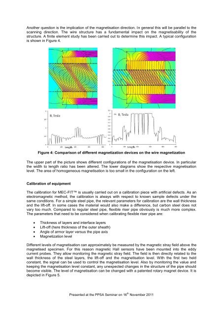
Figure 4: Comparison of different magnetization devices on the wire magnetization<br />
The upper part of the picture shows different configurations of the magnetisation device. In particular<br />
the width to length ratio has been altered. The lower diagrams show the respective magnetisation<br />
level. The area of homogeneous magnetisation is too small <strong>in</strong> the configuration on the left.<br />
Calibration of equipment<br />
The calibration <strong>for</strong> MEC-FIT is usually carried out on a calibration piece with artificial defects. As an<br />
electromagnetic method, the calibration is always with respect to known sample defects under the<br />
same conditions. For a simple steel pipe, the relevant parameters <strong>for</strong> calibration are the wall thickness<br />
and the lift-off. In some cases the material would also make a difference, but carbon steel does not<br />
vary too much. Compared to regular steel pipe, flexible riser pipe obviously is much more complex.<br />
The parameters that need to be considered when calibrat<strong>in</strong>g flexible riser pipe are:<br />
Thickness of layers and <strong>in</strong>terface layers<br />
Lift-off (here thickness of the outer sheath)<br />
Angle of armor layer versus the pipe axis<br />
Magnetization level<br />
Different levels of magnetisation can approximately be measured by the magnetic stray field above the<br />
magnetised specimen. For this reason magnetic Hall sensors have been mounted <strong>in</strong>to the eddy<br />
current probes. They allow monitor<strong>in</strong>g the magnetic stray field. The field is then directly related to the<br />
wall thickness of the steel layers, the lift-off and the magnetisation level. With the first two held<br />
constant, the signal can be used to control the magnetisation level. Also by monitor<strong>in</strong>g the value and<br />
keep<strong>in</strong>g the magnetisation level constant, any unexpected changes <strong>in</strong> the structure of the pipe should<br />
become visible. The level of magnetisation can be changed with a patented rotary magnet device. It is<br />
depicted <strong>in</strong> Figure 5.<br />
Presented at the PPSA Sem<strong>in</strong>ar on 16 th November 2011