Acoustic Reflectometry for Gas Pipelines – Monitoring Features in ...
Acoustic Reflectometry for Gas Pipelines – Monitoring Features in ...
Acoustic Reflectometry for Gas Pipelines – Monitoring Features in ...

You also want an ePaper? Increase the reach of your titles
YUMPU automatically turns print PDFs into web optimized ePapers that Google loves.
Abstract<br />
INSPECTION OF FLEXIBLE RISER PIPE WITH MEC-FIT<br />
By: K. Reber, Innospection Germany GmbH, Stutensee, Germany<br />
A. Bönisch, Innospection Ltd., Aberdeen, UK<br />
Flexible pipes are by nature complicated <strong>in</strong> design with its many vary<strong>in</strong>g material types, correspond<strong>in</strong>g<br />
to challenges <strong>in</strong> the <strong>in</strong>spection and <strong>in</strong>tegrity evaluation of the pipes.<br />
The anticipated concerns of the flexible pipe operators are defects such as cracks, corrosions, erosion<br />
and fatigue <strong>in</strong> the different layers of the wires under various tensional stress levels. While the<br />
<strong>in</strong>spection techniques currently available <strong>in</strong> the market are able to <strong>in</strong>spect only the near side layers <strong>for</strong><br />
wire disruptions, the far side layers rema<strong>in</strong> un<strong>in</strong>spected.<br />
Developed by Innospection, MEC-FIT TM is a Flexible Riser Inspection Tool us<strong>in</strong>g a patented<br />
technology that comb<strong>in</strong>es direct magnetic field l<strong>in</strong>es with eddy current field l<strong>in</strong>es, thus allow<strong>in</strong>g a<br />
deeper penetration <strong>in</strong>to the various armored layers. This technique enables the selection of the layers<br />
to be <strong>in</strong>spected, or alternatively allows the optimisation of the <strong>in</strong>spection <strong>for</strong> a specific layer from which<br />
a defect signal is received. The tool is capable of detect<strong>in</strong>g defects such as cracks, corrosions,<br />
material fatigue and general wall loss.<br />
Unlike traditional <strong>in</strong>spection methods, this system requires no couplant or annular flood<strong>in</strong>g.<br />
Deployed from an ROV, the <strong>in</strong>spection data is transmitted <strong>in</strong> real time via the ROV’s ma<strong>in</strong> umbilical<br />
back to the <strong>in</strong>spection computer at the ROV control unit.<br />
Introduction<br />
Flexible riser pipe or unbounded flexible pipe becomes more and more popular <strong>for</strong> applications <strong>in</strong> the<br />
offshore oil and gas <strong>in</strong>dustry. Initially merely <strong>in</strong>tended <strong>for</strong> the use of flexible risers <strong>in</strong> rough sea, this<br />
type of pipe type is now also used <strong>for</strong> flow l<strong>in</strong>es and other subsea applications. It is often also part of a<br />
plat<strong>for</strong>m to plat<strong>for</strong>m connector pipel<strong>in</strong>e, <strong>in</strong> comb<strong>in</strong>ation with regular rigid pip<strong>in</strong>g. In this context flexible<br />
riser pipe has also been <strong>in</strong>telligently pigged. However, due to the special structure of flexible riser<br />
pipe, most defects will not be revealed to <strong>in</strong>telligent pigs. Hence, flexible riser pipe, although it could<br />
be considered piggable <strong>in</strong> terms of passage, is not <strong>in</strong>spectable.<br />
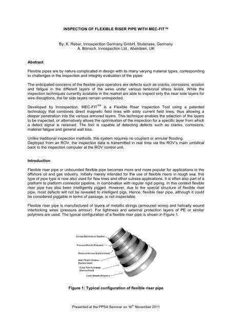
Flexible riser pipe is manufactured of layers of metallic str<strong>in</strong>gs (armoured wires) and helically wound<br />
<strong>in</strong>terlock<strong>in</strong>g wires (pressure armour). For tightness and external protection layers of PE or similar<br />
polymers are used. The typical configuration of a flexible riser pipe is shown <strong>in</strong> Figure 1.<br />
Figure 1: Typical configuration of flexible riser pipe<br />
Presented at the PPSA Sem<strong>in</strong>ar on 16 th November 2011
Flexible riser pipe is hence a challenge to the <strong>in</strong>spection service <strong>in</strong>dustry and several jo<strong>in</strong>t <strong>in</strong>dustry<br />
projects have been launched to tackle this problem [1, 2 and 4]. The multi-layered structure of the<br />
flexible riser pipe presents a problem <strong>for</strong> most of the typical NDT-Technologies employed <strong>in</strong> regular<br />
steel pipe. While Ultrasonic based technologies often have the advantage of yield<strong>in</strong>g <strong>in</strong><strong>for</strong>mation also<br />
from non-metallic material, the coupl<strong>in</strong>g between different layers often prevents a complete picture.<br />
Electromagnetic methods, <strong>in</strong> contrast, will select conductive material, while other material, like<br />
polymers will not be considered. The subject rema<strong>in</strong>s an area of active research, but solutions<br />
target<strong>in</strong>g specific concerns are now available.<br />
Defects <strong>in</strong> flexible riser pipe<br />
The flaws and defects that flexible riser pipe may suffer from are quite manifold. As a matter of fact<br />
rais<strong>in</strong>g the issue with different operators it is likely that the mentioned issues will differ widely.<br />
However, a few ma<strong>in</strong> concerns have risen. In particular as the lifetime of flexible riser pipe is deemed<br />
to be governed by fatigue-life, fatigue related defects are expected. While macroscopically fatigue will<br />
result <strong>in</strong> a reduced material strength, microscopically it will be the emergence of cracks that constitute<br />
a possible route to failure. With the armoured layers designed to take the ma<strong>in</strong> part of the bend<strong>in</strong>g<br />
stresses, this layer would be most prone to crack<strong>in</strong>g.<br />
In addition <strong>in</strong>evitable damages <strong>in</strong> the outer sheath will lead to the <strong>in</strong>gress of water. This can cause<br />
corrosion <strong>in</strong> the outer layers of the tensile armour. F<strong>in</strong>ally any overbend<strong>in</strong>g of the pipe can lead to an<br />
unlock<strong>in</strong>g of the pressure armour or to fatigue crack<strong>in</strong>g <strong>in</strong> the clamp<strong>in</strong>g parts of the pressure armour.<br />
Further defects like erosion have been reported.<br />
Pigg<strong>in</strong>g flexible riser pipe<br />
As mentioned previously the uneven <strong>in</strong>ner surface of a carcass does not render flexible pipe<br />
unpiggable. Intelligent pigs have passed through flexible pipe many times. No major problem has been<br />
reported. Concern<strong>in</strong>g defect detection, the <strong>in</strong>spection is very much limited to the <strong>in</strong>side, i.e. the<br />
carcass. Distortions and changes <strong>in</strong> the structure, unlock<strong>in</strong>g etc. usually become visible <strong>in</strong> such<br />
surveys. However, MFL as well as UT-based <strong>in</strong>telligent pigs have a limitation <strong>in</strong> penetrat<strong>in</strong>g further<br />
<strong>in</strong>to the pipe. In pr<strong>in</strong>ciple MFL could still detect larger defects <strong>in</strong> the <strong>in</strong>ner layers, but the resolution<br />
would be reduced. Precaution shall be taken when us<strong>in</strong>g MFL-tools with carbon steel brushes <strong>in</strong><br />
sta<strong>in</strong>less steel carcasses. A metallurgical <strong>in</strong>vestigation is required to avoid “after-rust”.<br />
Figure 2: View of a flexible riser pipe by a UT Wall thickness tool. Courtesy of NDT Systems &<br />
Services AG us<strong>in</strong>g L<strong>in</strong>eExplorer UM<br />
Prior technologies<br />
One of the most often applied techniques is radiography [1, 3]. While this technique shows high<br />
resolution images, the ease of deployment is somewhat limited. It may turn out to be an excellent<br />
verification technique. Another electromagnetic technology is MAPS [4]. This technology is currently <strong>in</strong><br />
Presented at the PPSA Sem<strong>in</strong>ar on 16 th November 2011
use <strong>for</strong> monitor<strong>in</strong>g the condition of flexible riser pipe at fixed positions. F<strong>in</strong>ally UT pulse-echo is also<br />
employed from an ROV [2]. This technique is ma<strong>in</strong>ly used <strong>for</strong> the detection of flooded annuli.<br />
Application of Eddy Current Technology<br />
Standard eddy current <strong>in</strong>strumentation is only sensitive to the surface of a metallic material. Even this<br />
can be quite a benefit <strong>for</strong> the <strong>in</strong>spection of flexible riser pipe [5]. However, modifications of the<br />
standard eddy current technologies allow <strong>for</strong> the <strong>in</strong>spection of deeper structures. At Innospection<br />
magnetically biased eddy current has been found to be a versatile method <strong>for</strong> the <strong>in</strong>spection of ferritic<br />
steel structures. The technology is also known under the trade name of SLOFEC. For the modification<br />
and adaptation to flexible riser <strong>in</strong>spection it is now known as MEC-FIT.<br />
The idea of MEC-FIT is to use an eddy current coil on ferromagnetic material and to magnetise the<br />
section of ferritic steel components at the same time. The magnetisation has several effects. It<br />
changes the permeability of the material. Hence, the penetration depth <strong>in</strong>creases. At the same time<br />
changes <strong>in</strong> permeability due to different flux distribution become visible. With these effects also<br />
defects embedded <strong>in</strong> the material can be picked-up with eddy current sensors.<br />
The pr<strong>in</strong>ciple of measurement is related to MFL-measurement, but the set-up works at lower<br />
magnetisation levels. S<strong>in</strong>ce only moderate levels of magnetisation are required, the method works to<br />
higher wall thickness pipe, or through several millimetres of coat<strong>in</strong>g thickness.<br />
The follow<strong>in</strong>g will show different applications on pipe systems. Some are not used <strong>for</strong> external<br />
<strong>in</strong>spection, but could <strong>in</strong> pr<strong>in</strong>ciple work from the <strong>in</strong>side as well. Obviously one difference to MFL is that<br />
the level of magnetisation should be adjusted. In contrast <strong>in</strong> MFL the magnetisation level should<br />
always be as high as possible.<br />
One of the most def<strong>in</strong><strong>in</strong>g aspects of flexible riser pipe is the presence of wires or str<strong>in</strong>gs runn<strong>in</strong>g<br />
helically around the pipe. This has a fundamental impact on electromagnetic NDE methods. The<br />
question of the scann<strong>in</strong>g and magnetisation direction needs to be considered. Several configurations<br />
can be conceived. A certa<strong>in</strong> level of magnetisation needs to be achieved; hence the magnetisation<br />
cannot deviate too much from the direction of the wires. There are at least two wir<strong>in</strong>g directions. For<br />
mechanical reasons only axial and circumferential scann<strong>in</strong>g are reasonable. In addition the employed<br />
probes usually yield a strong signal <strong>for</strong> the gaps between the wires. Refer to Figure 3 <strong>for</strong> a sample<br />
measurement of 4 mm thick armour wires, 12 mm <strong>in</strong> width and a gap of app. 2 mm.<br />
Figure 3: Signal of gaps between wires as a function of scann<strong>in</strong>g direction<br />
measured versus the pipe axis.<br />
Typical flexible riser pipe has angles between 35º and 45º. With the two layers wound <strong>in</strong> opposite<br />
directions an angle of 45º would be a cross<strong>in</strong>g of the layers at right angles. As can be seen <strong>in</strong> Figure 3<br />
the probes are designed such that the signal of a gap just disappears at the typical angle. It is known<br />
that the gaps are not at all uni<strong>for</strong>m <strong>in</strong> flexible riser pipe. It may be <strong>in</strong>terest<strong>in</strong>g to be able to detect larger<br />
gaps <strong>in</strong> the armour layer. Larger gaps do not necessarily constitute a defect, but it may be used as a<br />
reference location <strong>in</strong> a structure that may appear very homogeneous otherwise.<br />
Presented at the PPSA Sem<strong>in</strong>ar on 16 th November 2011
Another question is the implication of the magnetisation direction. In general this will be parallel to the<br />
scann<strong>in</strong>g direction. The wire structure has a fundamental impact on the magnetisability of the<br />
structure. A f<strong>in</strong>ite element study has been carried out to determ<strong>in</strong>e this impact. A typical configuration<br />
is shown <strong>in</strong> Figure 4.<br />
Figure 4: Comparison of different magnetization devices on the wire magnetization<br />
The upper part of the picture shows different configurations of the magnetisation device. In particular<br />
the width to length ratio has been altered. The lower diagrams show the respective magnetisation<br />
level. The area of homogeneous magnetisation is too small <strong>in</strong> the configuration on the left.<br />
Calibration of equipment<br />
The calibration <strong>for</strong> MEC-FIT is usually carried out on a calibration piece with artificial defects. As an<br />
electromagnetic method, the calibration is always with respect to known sample defects under the<br />
same conditions. For a simple steel pipe, the relevant parameters <strong>for</strong> calibration are the wall thickness<br />
and the lift-off. In some cases the material would also make a difference, but carbon steel does not<br />
vary too much. Compared to regular steel pipe, flexible riser pipe obviously is much more complex.<br />
The parameters that need to be considered when calibrat<strong>in</strong>g flexible riser pipe are:<br />
Thickness of layers and <strong>in</strong>terface layers<br />
Lift-off (here thickness of the outer sheath)<br />
Angle of armor layer versus the pipe axis<br />
Magnetization level<br />
Different levels of magnetisation can approximately be measured by the magnetic stray field above the<br />
magnetised specimen. For this reason magnetic Hall sensors have been mounted <strong>in</strong>to the eddy<br />
current probes. They allow monitor<strong>in</strong>g the magnetic stray field. The field is then directly related to the<br />
wall thickness of the steel layers, the lift-off and the magnetisation level. With the first two held<br />
constant, the signal can be used to control the magnetisation level. Also by monitor<strong>in</strong>g the value and<br />
keep<strong>in</strong>g the magnetisation level constant, any unexpected changes <strong>in</strong> the structure of the pipe should<br />
become visible. The level of magnetisation can be changed with a patented rotary magnet device. It is<br />
depicted <strong>in</strong> Figure 5.<br />
Presented at the PPSA Sem<strong>in</strong>ar on 16 th November 2011
Figure 5: Patented design <strong>for</strong> the adaptation of the magnetization level<br />
By rotat<strong>in</strong>g the magnet the field can be changed from zero to a maximum level. Measurements are<br />
shown <strong>in</strong> Figure 6 <strong>for</strong> various pipe configurations. Also the open circuit, i.e. the device removed from<br />
any steel material is shown. It can be seen, that once a pipe type is chosen, the Hall device can be<br />
used to verify the magnetic flux level.<br />
Figure 6: Magnetic field measured by the Hall sensor <strong>for</strong> different structures<br />
as the magnet is “turned on”<br />
In addition the values can be comb<strong>in</strong>ed with the <strong>in</strong><strong>for</strong>mation of the open circuit. This will allow<br />
calculat<strong>in</strong>g a value directly proportional to a permeability. This value does of course not only <strong>in</strong>clude<br />
material permeability but also geometry effects. The result is shown <strong>in</strong> Figure 7.<br />
Presented at the PPSA Sem<strong>in</strong>ar on 16 th November 2011
Figure 7: Calculated “permeability” <strong>in</strong> arbitrary units. It is a comb<strong>in</strong>ation of material and<br />
geometrical effects.<br />
The maximum signal is expected at the steepest slope of this curve. This would be around 20º turn<strong>in</strong>g<br />
angle. Experimentally this could be verified. For the calibration of defects the magnetization level will<br />
be set to the optimum level with lift-off and wall thickness fixed. It can be seen <strong>in</strong> Figure 6 that this<br />
value can also be <strong>in</strong>terpolated once sufficient experimental data is obta<strong>in</strong>ed.<br />
With regards to calibration <strong>for</strong> defect siz<strong>in</strong>g, artificial defects can be used if the “electromagnetic<br />
environment” is comparable. This means that material properties and configuration should be similar<br />
as <strong>in</strong> the actual pipe.<br />
For ga<strong>in</strong><strong>in</strong>g experience with the device, test<strong>in</strong>g on actual defects <strong>in</strong> riser pipe is very important.<br />
Figure 8 shows the signals of a scan of the complete surface of a flexible riser pipe of app. 2 m length.<br />
This particular flexible pipe has been <strong>in</strong> service <strong>for</strong> many years and was known to be flooded.<br />
Radiographic <strong>in</strong>spection has revealed an unlock<strong>in</strong>g of the ξ-wire. Depicted are the signals as the scan<br />
was per<strong>for</strong>med along the axis. The axis of the pipe is from left to right. The figure is a mosaic of<br />
several scans and displays the full circumference <strong>in</strong> the vertical extent.<br />
The area with the presumed unlock<strong>in</strong>g is found <strong>in</strong> the center of the picture, where signals extend <strong>in</strong> the<br />
vertical direction. Also two stripes runn<strong>in</strong>g from the lower left to the upper right show larger gaps <strong>in</strong> the<br />
armored wire. It is well known that <strong>in</strong> flexible riser pipe the armored wires are not equally spaced, but<br />
the gap size can vary. With larger gap size the gap will yield a signal as shown <strong>in</strong> Figure 3.<br />
Figure 8: Surface of a flexible riser pipe that has been <strong>in</strong> service <strong>for</strong> many years and was<br />
known to be flooded. Radiographic <strong>in</strong>spection has revealed an unlock<strong>in</strong>g of the Zeta-wire.<br />
Presented at the PPSA Sem<strong>in</strong>ar on 16 th November 2011
Operational aspects<br />
One of the advantages of electromagnetic test<strong>in</strong>g over ultrasonic test<strong>in</strong>g is that the surface preparation<br />
does not require as much scrut<strong>in</strong>y. Usually clean<strong>in</strong>g is achieved by water jett<strong>in</strong>g. The nozzles can be<br />
mounted on a crawler tool as shown <strong>in</strong> the left <strong>in</strong> Figure 9. Water jett<strong>in</strong>g results <strong>in</strong> a quite clean<br />
surface. Often a simple scrap<strong>in</strong>g action may yield sufficient results. The magnetization unit with the<br />
sensors is mounted on wheels. Wheels will prevent the metallic parts from touch<strong>in</strong>g the Outer sheath<br />
<strong>in</strong> order to avoid any damage. The unit is hung <strong>in</strong>to a frame with drives to move the scann<strong>in</strong>g unit<br />
around the pipe. The unit is shown on the right <strong>in</strong> Figure 9.<br />
Figure 9: Left: The scanner <strong>in</strong>side the frame of the MEC-FIT unit. Right: A different sub-sea<br />
scanner unit is equipped with nozzles <strong>for</strong> a prior clean<strong>in</strong>g operation<br />
The tool is deployed with an ROV as shown <strong>in</strong> Figure 10. Data is routed through the umbilical of the<br />
ROV and received top-side <strong>for</strong> immediate analysis.<br />
Figure 10: Deployment of the <strong>in</strong>spection tool by ROV (Together with Fugro)<br />
To scan the compete surface the scanner will move up and down and rotate around the axis such that<br />
the pipe is covered by a meander<strong>in</strong>g path. To move to the next location the tool can climb up and<br />
down on the riser.<br />
Presented at the PPSA Sem<strong>in</strong>ar on 16 th November 2011
Conclusion<br />
MEC-FIT offers a unique possibility to scan larger areas of the surface of flexible riser pipe <strong>for</strong> several<br />
k<strong>in</strong>ds of defects. The deployment is relatively easy. As the measurement is carried out with a mov<strong>in</strong>g<br />
device, absolute rest is not required. The unconventional layered structure will only pose a problem <strong>for</strong><br />
<strong>in</strong>spection <strong>for</strong> deeply imbedded small defects, like cracks <strong>in</strong> a zeta-wire or <strong>in</strong> deep water pipes with<br />
four armoured layers.<br />
References<br />
[1] FlexiRiserTest 2010. The FlexiRiserTest Project is a collaboration between the follow<strong>in</strong>g<br />
organisations: Computerised In<strong>for</strong>mation Technology (CIT) Ltd, Technical Software Consultants<br />
(TSC) Inspection Systems Ltd, Naftosol SA, Wellstream International Ltd, Petrobras, EuroNDT<br />
Ltd, Zenon SA, Research Institute Juelich and TWI Ltd. This project is managed and coord<strong>in</strong>ated<br />
by TWI Ltd, and is partly funded by the European Commission under the Horizontal<br />
Research Activities Involv<strong>in</strong>g SMEs: Cooperative Research Programme reference COOP-CT-<br />
2006-032680.<br />
[2] Riser End of Life JIP headed by Flexlife: 2010<br />
[3] Automated radiographic <strong>in</strong>spection of flexible risers: A Feasibility Study, R.Mallett et.al., TWI,<br />
Insight Sep 2005<br />
[4] HOIS JIP headed by ESR Technology, see <strong>for</strong> <strong>in</strong>stance: Update on HOIS JI work… Integrity<br />
Management of unbounded flexible pipel<strong>in</strong>es, Pittodrie Hotel Inverurie, 27 th November 2008.<br />
[5] Force Institute /Flexible-pipe-monitor<strong>in</strong>g/specialisedndtservices<br />
Presented at the PPSA Sem<strong>in</strong>ar on 16 th November 2011