
Create successful ePaper yourself
Turn your PDF publications into a flip-book with our unique Google optimized e-Paper software.
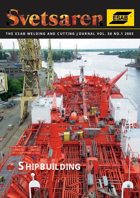
THE ESAB WELDING AND CUTTING JOURNAL VOL. 58 NO.1 2003<br />
<strong>SHIPBUILDING</strong>
THE ESAB WELDING AND CUTTING JOURNAL VOL. 58 NO.1 2003<br />
Articles in Svetsaren may be reproduced without permission but with<br />
an acknowledgement to ESAB.<br />
Publisher<br />
Bertil Pekkari<br />
Editor<br />
Ben Altemühl<br />
Editorial committee<br />
Björn Torstensson, Johnny Sundin, Johan Elvander, Lars-Erik Stridh, Lars-Göran Eriksson,<br />
Dave Meyer, Tony Anderson, Peter Budai, Arnaud Paque, Klaus Blome<br />
3<br />
6<br />
9<br />
16<br />
Address<br />
SVETSAREN, ESAB AB, Marketing Communication<br />
c/o P.O. Box 8086, 3503 RB Utrecht, The Netherlands<br />
Internet address<br />
http://www.esab.com<br />
E-mail: info@esab.se<br />
Lay-out: Duco Messie, printed in the Netherlands<br />
Contents Vol. 58 No. 1 2003<br />
New developments within the Aluminium<br />
Shipbuilding Industry<br />
Recent developments in the construction of<br />
fast patrol and transportation vessels for the<br />
US military by Bollinger/Incat Inc., applying<br />
the latest higher strength varieties of the<br />
5083 aluminium marine alloy.<br />
FSW – possibilities in Shipbuilding<br />
ESAB LEGIO TM friction stir welding<br />
machines expand the scope of application of<br />
aluminium in shipbuilding by providing<br />
accurate welded components that require<br />
minimal fit-up work, and by allowing the use<br />
of high strength aluminium grades that were<br />
formerly regarded as un-weldable.<br />
Efficient production of Stiffeners for<br />
Shipbuilding<br />
ESAB’s new IT-100 automatic T-beam welding<br />
machine offers highly productive, automated<br />
welding in an unmanned production<br />
environment to shipbuilders and other fabricators<br />
with a need to produce beams.<br />
ESAB Railtrack FW 1000 aids fabrication<br />
efficiency of the world’s largest aluminium<br />
yacht<br />
Mechanised MIG welding with Railtrack<br />
FW 1000 for horizontal and vertical butt<br />
welds has greatly improved the welding efficiency<br />
in the building of the world’s largest<br />
alumium yacht at Royal Huisman, The<br />
Netherlands.<br />
18<br />
24<br />
26<br />
29<br />
34<br />
Photo courtesy Stocznia Szczecinska<br />
Nowa, Poland. The Bow Sun, the world’s<br />
largest duplex chemical tanker. The<br />
FCAW of a series of these tankers will be<br />
covered in the next issue of Svetsaren.<br />
How much heat can various steels and<br />
filler metals withstand?<br />
The article reports on research into the maximum<br />
heat input acceptable for high tensile<br />
construction steels.<br />
ESAB Brazil provides BrasFELS shipyard<br />
with extra FCAW productivity for offshore<br />
vessels<br />
The BrasFELS shipyard, in Angra dos Reis,<br />
Brazil, increases welding productivity with<br />
OK Tubrod 75 basic cored wire for low-temperature<br />
applications.<br />
Secure downhill MAG welding of butt- and<br />
fillet welds with ESAB OK Tubrod 14.12<br />
The article reports on highly productive<br />
downhill welding procedures used by German<br />
shipyards for thin-walled applications using<br />
OK Tubrod 14.12 metal-cored wire.<br />
Thermal Bevelling Techniques<br />
The article discusses the thermal bevelling<br />
techniques available from ESAB, highlighting<br />
several cutting processes and a variety of<br />
plate edge preparation applications.<br />
Stubends & Spatter<br />
Short news and product introductions.
New developments within the<br />
Aluminium Shipbuilding Industry<br />
By Tony Anderson - Technical Services Manager - AlcoTec Wire Corporation<br />
The article describes recent developments in the construction of fast patrol and<br />
transportation vessels for the US military by Bollinger/Incat Inc., applying the latest<br />
higher strength varieties of the 5083 aluminium marine alloy. The section on weldability<br />
addresses the open-end questions that surround these very new alloys.<br />
Figure 1. The Spearhead - new generation of 98-metre wavepiercers<br />
The creation of this article was promoted by current<br />
activities within the United States military, the extraordinary<br />
developments in aluminium shipbuilding that<br />
have been taking place in Australia, and the creation<br />
of new high strength aluminium alloys, primarily in<br />
Europe, for the shipbuilding industry.<br />
I was fortunate enough recently to visit Incat Tasmania<br />
Pty Ltd. (Shipbuilding) off the southeast coast of<br />
Australia. This manufacturer has over the years taken<br />
aluminium shipbuilding to exciting new levels. In 1977<br />
they launched their first high-speed catamaran, and<br />
today they are manufacturing the new generation of 98metre<br />
(100 plus yards) wavepiercers that are being evaluated<br />
by the United States military (see figure 1).<br />
Incat has constructed more than 50 vessels of varying<br />
lengths. The company’s first passenger/vehicle ferry was<br />
delivered in 1990, a 74-metre Wave Piercing Catamaran<br />
with a maximum deadweight capacity of 200 tonnes.<br />
The more recent 98m Evolution 10B range has a deadweight<br />
four times that amount. While Incat-built ferries<br />
initially revolutionized transport links around the<br />
United Kingdom, today its ships operate in North and<br />
South America, Australasia, the Mediterranean, and<br />
throughout greater Europe. Incat’s extensive shipbuilding<br />
activity is conducted from a modern facility with<br />
over 32,000 m 2 under cover, located at Hobart’s Prince<br />
of Wales Bay Tasmania.<br />
Aluminium Welded Ships Within The United<br />
States Military.<br />
In response to great interest from the US military in<br />
high-speed craft, a strategic alliance has been formed<br />
between Incat, the premier builder of the world’s fastest<br />
vehicle/passenger ferries, and Bollinger, a proven<br />
builder of a variety of high speed, reliable and efficient<br />
patrol boats for the US Navy and Coast Guard.<br />
Svetsaren no. 1 • 2003 • 3
Figure 2. GMAW being used on high strength large aluminium structural components at<br />
Incat’s Shipyard in Australia<br />
The US government has awarded Bollinger/Incat USA<br />
the charter for a High Speed Craft (HSC) for a multiservice<br />
program operated by various arms of the US<br />
military. The HSC Vessel, now known as Joint Venture<br />
HSV-X1, is being used for evaluation and demonstration<br />
trials in order to assess the usefulness of such technology<br />
in US military and Coast Guard applications.<br />
Another charter, the USAV TSV-1X Spearhead is the US<br />
Army’s first Theater Support Vessel (TSV) and is part of<br />
the Advanced Concept Technology Demonstrator<br />
(ACTD) program by the Office of the Secretary of<br />
Defense and the US Army. TSVs promise to change the<br />
way the US Army gets to the fight by allowing personnel<br />
to quickly deliver intact packages of combat-ready<br />
soldiers and leaders with their equipment and supplies.<br />
Another order, from Military Sealift Command,<br />
Washington, D.C., calls for the lease of a 98m craft<br />
from Bollinger/Incat USA, LLC, Lockport, La., to<br />
support US Navy Mine Warfare Command. The ship<br />
will be capable of maintaining an average speed of 35<br />
knots or greater, loaded with 500 short tons, consisting<br />
of 350 personnel and military equipment, have a minimum<br />
operating range of 1100 nautical miles at 35<br />
knots, and a minimum transit range of 4000 nautical<br />
miles at an average speed of 20 knots. The craft will be<br />
capable of 24-hour operations at slow speeds (3-10<br />
knots) for small boat and helicopter operations.<br />
4 • Svetsaren no. 1 • 2003<br />
New Developments in High Strength<br />
Aluminium Alloys for Marine Applications<br />
Until fairly recently, the most popular base material<br />
used for aluminium shipbuilding, 5083, has had very little<br />
rivalry from other alloys. The 5083 base alloy was<br />
first registered with the Aluminium Association in 1954,<br />
and while often referred to as a marine aluminium alloy,<br />
has been used for many applications other than shipbuilding.<br />
The popularity of the 5083 alloy within the<br />
shipbuilding industry has been largely based on its availability<br />
and also its ability to provide an aluminium alloy<br />
with excellent strength, corrosion resistance, formability<br />
and weldability characteristics. Other lower strength<br />
alloys, such as 5052 and 5086, have been used for the<br />
manufacture of usually smaller, lower stressed and typically<br />
inland lake boats, but 5083 has been predominant<br />
in the manufacture of ocean-going vessels.<br />
In recent years, progress has been achieved by aluminium<br />
producers in the development of improved<br />
aluminium alloys specifically targeted at the shipbuilding<br />
industry. In 1995 the aluminium manufacturer,<br />
Pechiney of France, registered the aluminium alloy<br />
5383 and promoted this material to the shipbuilding<br />
industry as having improvements over the 5083 alloy.<br />
These improvements provided potential for significant<br />
weight savings in the design of aluminium vessels and<br />
included a minimum of 15% increase in the post-weld
yield strength, improvements in corrosion properties<br />
and a 10% increase in fatigue strength. These developments,<br />
coupled with formability, bending, cutting, and<br />
weldability characteristics, at least equal to that of<br />
5083, made the 5383 alloy very attractive to designers<br />
and manufacturers who were pushing the limits to produce<br />
bigger and faster aluminium ships.<br />
More recently in 1999, the aluminium manufacturer,<br />
Corus Aluminium Walzprodukte GmbH in Koblenz<br />
(Germany), registered the aluminium base alloy 5059<br />
(Alustar) with the American Aluminium Association.<br />
This alloy was also developed as an advanced material<br />
for the shipbuilding industry providing significant<br />
improvements in strength over the traditional 5083<br />
alloy. The 5059 alloy is promoted by Corus as providing<br />
improvements in minimum mechanical properties<br />
over alloy 5083. These improvements are referenced as<br />
being a 26% increase in yield strength before welding<br />
and a 28% increase in yield strength (with respect to<br />
alloy 5083) after welding of H321/H116 temper plates<br />
of the AA5059 (Alustar alloy).<br />
Welding the New Aluminium Alloys<br />
The welding procedures used for these high strength<br />
alloys are very similar to the procedures used when<br />
welding the more traditional 5083 base alloys. The<br />
5183 filler alloy and the 5556 filler alloy are both suitable<br />
for welding 5383 and 5059 base alloys. These<br />
alloys are predominantly welded with the GMAW<br />
process using both pure argon and a mixture of<br />
argon/helium shielding gas. The addition of helium of<br />
up to 75% is not uncommon and is useful when welding<br />
thicker sections. The helium content provides higher<br />
heat during the welding operations, which assists in<br />
combating the excessive heat sink when welding thick<br />
plate. The extra heat associated with the helium shielding<br />
gas also helps to reduce porosity levels. This is very<br />
useful when welding the more critical joints such as<br />
hull plates that are often subjected to radiographic<br />
inspection.<br />
The design strength of these alloys are available from<br />
the material manufacturer, however, there would<br />
appear to be little as-welded strength values incorporated<br />
in current welding specifications. Certainly these<br />
relatively new base alloys are not listed materials within<br />
the AWS D1.2 Structural Welding Code –<br />
Aluminium, and consequently no minimum tensile<br />
strength requirements are included in this code. If this<br />
material continues to be used for welded structures,<br />
there will be a need to address this situation by establishing<br />
appropriate tensile strength values and to<br />
include them in the appropriate welding codes.<br />
Early testing on the 5059 (Alustar) base alloy indicated<br />
that problems could be encountered relating to the<br />
weld metal being capable of obtaining the minimum<br />
tensile strength of the base material heat affected<br />
zone. One method used to improve the weld tensile<br />
strength was to increase the amount of alloying elements<br />
drawn from the plate material into the weld.<br />
This was assisted by the use of helium additions to the<br />
shielding gas, which produces a broader penetration<br />
profile that incorporates more of the base material.<br />
The use of 5556 filler alloy rather than the 5183 filler<br />
can also help to increase the strength of the deposited<br />
weld material.<br />
Obviously these high performance vessels require high<br />
quality welding. The training of welders, development<br />
of appropriate welding procedures, and implementation<br />
of suitable testing techniques are essential in producing<br />
such a high performance product.<br />
The future<br />
With the increasing demand to create larger and faster<br />
ships, particularly for military service, and the development<br />
of new improved, high-performance aluminium<br />
base materials, it is apparent that aluminium welding<br />
has acquired an interesting and important place within<br />
the shipbuilding industry. Also, with the pending introduction<br />
of this unique technology into the United<br />
States, it is important that designers, manufacturers,<br />
and particularly welders and welding engineers are adequately<br />
trained and familiar with this new technology.<br />
About The Author:<br />
Tony Anderson is Technical Services Manager of<br />
AlcoTec Wire Corporation, MI, USA, Chairman of<br />
the Aluminium Association Technical Advisory<br />
Committee on Welding and Joining, Chairman of<br />
the American Welding Society (AWS) Committee<br />
for D10.7 Gas Shielded Arc Welding of Aluminium<br />
Pipe, Chairman of the AWS D8.14 Committee for<br />
Automotive and Light Truck Components Weld<br />
Quality - Aluminium Arc Welding and Vice<br />
Chairman of the AWS Committee for D1.2<br />
Structural Welding Code - Aluminium.<br />
Svetsaren no. 1 • 2003 • 5
FSW – possibilities in Shipbuilding<br />
By: Kari Lahti, ESAB AB Automation, Gothenburg, Sweden<br />
Aluminium is increasingly being recognised as an alternative, weight-saving<br />
construction material in shipbuilding. Friction Stir Welding expands the scope<br />
of application of this material by providing accurate welded components that<br />
require minimal fit-up work, and by allowing the use of high strength aluminium<br />
grades that were formerly regarded as un-weldable. ESAB LEGIO modular<br />
friction stir welding machines bring this new welding process within reach at<br />
moderate investment costs. Here we discuss the main benefits of friction stir<br />
welded aluminium components in ship structures.<br />
Figure 1. Friction stir welded, straight panels under inspection<br />
at ESAB FSW Center of Excellence in Sweden.<br />
Assembly work has never been easier<br />
Imagine if a large catamaran could be constructed<br />
from building blocks, just like a toy boat. All pieces<br />
would fit perfectly to each other and dimensional accuracy<br />
and changes could be mastered to full degree.<br />
Friction Stir Welding takes the first step towards such<br />
assembly work in shipbuilding. Due to the low heatinput<br />
during joining and resulting very low residual<br />
stresses, the welded components are accurate and minimal<br />
fit-up work is needed. The resulting savings in<br />
both time and money are obvious. Since this creates<br />
competitive advantage to the users of FSW pre-fabricates,<br />
documented information of actual savings is not<br />
very often reported. However, Midling et. al. 2000,<br />
gives an idea of the possibilities gained by friction stir<br />
welded pre-fabricated panels from a panel producers<br />
point of view:<br />
• Industrial production with a high degree of completion.<br />
• Extended level of repeatability ensuring uniform<br />
level of performance, quality and narrow tolerances.<br />
• The flexible production equipment and capacity allows<br />
customer built solutions with reliability of delivery.<br />
6 • Svetsaren no. 1 • 2003<br />
• The completed panel units are inspected and<br />
approved at present by classification authorities such<br />
as DNV, RINA and Germanischer Lloyds.<br />
• The high level of straightness of the panels ensure easy<br />
assembly at yard, which means less manual welding.<br />
• Supplementary work for the customer, such as less<br />
need for floor levelling and preparation for floor coverings<br />
also is a major cost saving with FSW panels.<br />
What is gained after the welding?<br />
One of the most attractive features of friction stir<br />
welded products is that they are ready-to-use. No time<br />
consuming post-weld treatment such as grinding, polishing<br />
or straightening is needed. With proper design<br />
the elements are ready-to-use directly after welding.<br />
However, it is important to keep in mind that designs<br />
which are made for MIG or TIG welding, are not necessarily<br />
suitable for friction stir welding. The limiting<br />
factor often being the relatively high down-force needed<br />
when friction stir welding. A proper support in a<br />
form of backing bar or design change are often needed<br />
(Figure 2). Once done, repeatability reaches levels previously<br />
not experienced in welding.<br />
Figure 2. Designs suitable for friction stir welding of 2-skin<br />
profiles in aluminium. Illustration: ESAB
When producing large surfaces like walls or floors,<br />
besides the straightness of the panels, also the resulting<br />
reflections are an important and expensive issue to<br />
consider. A lot of time is spent polishing and "makingup"<br />
surfaces which are architecturally visible. In FSW<br />
prefabricated panels, the reflections are merely caused<br />
by the surface appearance of the aluminium plates and<br />
profiles in the as-delivered state, not by the reflections<br />
caused by welding heat input.<br />
Why use aluminium instead of steel?<br />
One excuse of not using aluminium has always been<br />
"that it is not as strong as steel." True – and not true. It,<br />
of course, depends also on the alloy to be used, and surprisingly<br />
enough, there are aluminium alloys which are<br />
as strong or even stronger than steels. For example the<br />
so called "ALUSTAR" has yield and tensile strenghts<br />
comparable to low-alloyed steel S235. AlCu4SiMg<br />
(AA2014) – an alloy typically used in aerospace applications<br />
–has siginficantly higher strength than alloys in<br />
5xxx- and 6xxx series which are typically used in shipbuilding.<br />
Some of these alloys just have not been used<br />
in shipbuilding before, due to their poor weldability!<br />
With friction stir welding, some of these barriers can be<br />
overcome – just imagine, for example, using strong<br />
alloy AA7021 for making aluminium floor panels even<br />
thinner, and gain weight savings by "thinking differently".<br />
In Figure 3 the weldability of various aluminium<br />
alloys is shown as a reminder. The typical alloys used in<br />
shipbuilding are from 5xxx –series due to their good<br />
corrosion resistance, or from 6xxx –series due to the<br />
strength. A dissimilar combination between these two<br />
alloys is of course also possible (Larsson et. al. 2000).<br />
An easy way to make small-scale pre-fabricated<br />
panels or components<br />
Figure 4 gives an idea of relatively easy implementation<br />
of FSW in shipbuilding. ESAB’s new LEGIO concept<br />
is ideal for fabrication of small batches of friction<br />
stir welded panels. The equipment is placed on the<br />
workshop right next to the asembly of the shiphull. The<br />
picture is from Estaleiros Navais do Mondego S.A.<br />
Shipyard in Portugal. Even small batches can effectively<br />
be welded on-site.<br />
The LEGIO concept represents a modular, modern<br />
design available for friction stir welding. A series of<br />
standardised welding machines puts FSW at everyone’s<br />
reach. Welds with highest quality are produced<br />
even in small batches. Table 1 summarises the range of<br />
machines available in the LEGIO system. A size "3"<br />
should cover the needs of most shipyards.<br />
Figure 3. Weldability of different aluminium alloys. ” TWI.<br />
Figure 4. FSW LEGIO 3UT installed next to shiphull<br />
production line at Estaleiros Navais do Mondego S.A.<br />
Shipyard in Portugal.<br />
Figure 5. Hat profiles stacked for shipping. Definitely no<br />
straightening needed after the welding process.<br />
Photo: Hydro Aluminium.<br />
Svetsaren no. 1 • 2003 • 7
Table 1. The family picture of the new modular LEGIO family for easy implementation of friction stir welding.<br />
Size Vertical Spindle AA 6000 AA 5000 AA 2000 CU<br />
downforce effect AA 7000 (oxygen free)<br />
FSW 1 6 kN 3 kW 3 mm 2 mm 1.5 mm 0.8 mm<br />
FSW 2 12.5 kN 5.5 kW 5 mm 3.5 mm 2.5 mm 1.5 mm<br />
FSW 3 25 kN 11 kW 10 mm 7 mm 5 mm 3 mm<br />
FSW 4 60 kN 18 kW 18 mm 10 mm 9 mm 7 mm<br />
FSW 5 100 kN 22 kW 35 mm 20 mm 18 mm 12 mm<br />
FSW 6 150 kN 45 kW 60 mm 40 mm 35 mm 25 mm<br />
FSW 7 200 kN 90 kW 100 mm 75 mm 70 mm 40 mm<br />
How to proceed?<br />
Friction Stir Welding is much easier to implement than<br />
most other welding processes. The welding operator<br />
does not need any special skills, since the parameters<br />
are repeatable and high quality is easily achieved time<br />
after time. You don’t need to be big and powerful to<br />
invest in Friction Stir Welding – the modular way. It<br />
may, however, make You big and powerful by shortening<br />
cycle times and improving the quality of Your<br />
products. Just dare to do it!<br />
References:<br />
Larsson H., Karlsson L., Svensson L-E, 2000. Friction<br />
Stir Welding of AA5083 and AA6082 Aluminium. In:<br />
Svetsaren 2(2000). 5 pp.<br />
Midling O.T., Kvåle, J.S. 1999. Industrialisation of the<br />
friction stir welding technology in panels production<br />
for the maritime sector. In: The 1 st International<br />
Symposium on Friction Stir Welding. Thousand Oaks,<br />
CA, USA 14-16 June. 7 pp.<br />
8 • Svetsaren no. 1 • 2003<br />
About The Author:<br />
Mr. Kari Erik Lahti graduated from Helsinki<br />
University of Technology, Finland, 1994 with a<br />
M.Sc. degree in welding technology. After working<br />
as a research scientist in the field of welding metalllurgy,<br />
he joined Oy ESAB in Finland 1997 and started<br />
as product manager for welding automation.<br />
In 1998 Kari Lahti finalised his Ph.D. in "nominal<br />
stress range fatigue of stainless steel fillet welds"<br />
Since 2002 he has been working at ESAB AB<br />
Göteborg, Sweden, currently as marketing manager<br />
for advanced engineering products.
Efficient production of Stiffeners for<br />
Shipbuilding<br />
By Herbert Kaufmann, ESAB AB, Welding Automation<br />
ESAB’s new IT-100 automatic T-beam welding machine offers highly productive,<br />
automated welding in an unmanned production environment to<br />
shipbuilders and other fabricators with a need to produce beams.<br />
Optimum welding speed, beyond 1m/min., is provided by double-sided<br />
tandem submerged arc heads. Web and flange are automatically longitudinally<br />
centered in the in-feed conveyor, whereas on-line straightening<br />
of the beams is provided by inductive heating, avoiding time-consuming<br />
post-weld straightening procedures.<br />
1. Introduction<br />
ESAB has marketed and distributed robust, manual<br />
T-beam welding equipment for many years, equipment<br />
design generally following market demand. Although,<br />
a typical T-beam welder was partly mechanized, all settings<br />
of the welding machine had to be carried out<br />
manually by an operator due to its prescribed welding<br />
procedures. Therefore, the design and control technology<br />
of such machines is fairly simple, relying heavily on<br />
highly skilled operators to produce parts of consistently<br />
high quality.<br />
Many companies, especially shipyards, are experiencing<br />
increasing competition from many other worldwide<br />
operating enterprises. To survive, in an often tough<br />
and continuously shrinking market, shipyards must<br />
now find new ways to increase their internal productivity.<br />
One way to increase productivity is to increase<br />
factory automation. Production equipment whose<br />
design provides the factory with a higher degree of<br />
automation also increases efficiency and quality levels.<br />
For example, modern control technology makes it also<br />
possible to schedule “tighter” production runs by presetting<br />
the production equipment with instruction sets<br />
important for unmanned operation. The control system<br />
can also be connected to an internal MRP system<br />
for even more efficient production efficiency.<br />
As suppliers of state-of-the-art welding equipment,<br />
ESAB has seen an increasing demand for more sophisticated<br />
production systems equipped with the latest control<br />
technology. To meet this demand, ESAB has developed<br />
an automated T-beam welding system, which can<br />
be used in an unmanned production environment.<br />
2. Equipment for T-beam Production<br />
Situated upstream and downstream of the T-beam welding<br />
machine there are a number of material handling<br />
equipment cells, including:<br />
• In-feed conveyor usually situated after a cutting<br />
machine.<br />
• Grinding and shot-blasting equipment.<br />
• Web raising station.<br />
• Web alignment station upstream to the T-beam<br />
welder.<br />
• T-beam welder with peripheral equipment.<br />
• Out-feed conveyor with raising/lowering capability.<br />
• Cooling bed.<br />
• Straightening equipment.<br />
• Shot-blasting equipment.<br />
• Priming booth.<br />
• Cutting equipment for notches and holes.<br />
• Centralized control system.<br />
Modern production equipment needs to be flexible to<br />
work efficiently in an automated environment. It is<br />
therefore of great importance to be able to integrate<br />
these work cells into a centralized computer system,<br />
which is then able to communicate with modern information<br />
systems (e.g. MRP).<br />
2.1 In-feed conveyor<br />
The beam welding system becomes more productive if<br />
the beam is supported and conveyed through the<br />
machine in a very precise manner. In other words, the<br />
precision of the in-feed conveyor will directly affect<br />
the precision of the finished beam (Figure 1).<br />
A raising station situated upstream of the in-feed conveyor<br />
will place the web in the middle of the flange and<br />
Svetsaren no. 1 • 2003 • 9
then feed it into the in-feed conveyor. The beam then<br />
stops after it passes through the first set of the vertical<br />
feed rollers. The flange width will be measured and its<br />
dimension will be transferred to the controller of the<br />
beam welder.<br />
Even if the measured flange width differs along the<br />
beam length, centering the web exactly on the center<br />
of the flange now becomes easier. If the measured<br />
dimension of the flange is out of tolerance an alarm<br />
will sound and then the operator can decide if the target<br />
beam should be welded or not.<br />
Before reaching the T-beam welder, longitudinal centering<br />
adjustment of the web and flange has been completed<br />
after the beam has passed through all three pairs<br />
of rollers. T-beams with a positive or negative value can<br />
be produced even though the offset defaults to “zero”.<br />
The traverse speed of the in-feed conveyor is synchronized<br />
with the beam welding speed, which is controlled<br />
by the T-beam welder.<br />
2.2 T-beam welder<br />
The newly developed IT-100 Automatic T-beam welding<br />
machine has been optimized for the production of<br />
symmetrical T-beams. With small modifications, the<br />
machine will weld other types of profiles and beams<br />
(Figure 2).<br />
All pre-set values for the T-beam welder, for example,<br />
of the beam sizes and associated weld parameters can<br />
be made by the operator or obtained from a customer’s<br />
production planning system. It is therefore possible to<br />
run the T-beam line with mixed production schedules<br />
of varying sizes of T-beams, without interrupting the<br />
ongoing production.<br />
Several features of the new IT-100 Automatic are<br />
worth mentioning. With the IT-100 Automatic, beams<br />
can now be welded without having to tack weld the<br />
web and flanges. Another important improvement is<br />
the automatic centering feature which always positions<br />
the web into the center of the flange even if the flange<br />
width varies. Also, welding 5 mm from the start and<br />
the end of the T-beam guarantees efficient utilization<br />
of T-beam material for the finished beam.<br />
The system’s main controller is an Allan Bradley PLC<br />
type Control Logic 5550. Internal communication is<br />
via a DeviceNet bus. All external devices are linked to<br />
the controller by an Ethernet bus system. The controller<br />
also uses a modem for remote supervision, to<br />
make programme alterations, and to become assessable<br />
for service diagnostics from the outside. Installation<br />
and specific production parameters (welding<br />
parameters and work piece dimensions) can be<br />
entered from the operators panel (Panel View 600).<br />
The operator can protect all settings with passwords.<br />
10 • Svetsaren no. 1 • 2003<br />
Figure 1. Infeed conveyor, front view.<br />
Technical data:<br />
Length of infeed conveyor 6000 mm<br />
Height of conveyor 720 mm<br />
Weight 6 tons<br />
No of flange/web rollers totally 6 (3 pairs of rollers)<br />
Rapid speed max. 16 m/min<br />
Figure 2. ESAB’s T-beam welder IT-100 Automatic.<br />
Technical Data<br />
Width of Flange 102 – 600mm<br />
Thickness of flange 10 – 41mm<br />
Height of Web 150 – 915mm<br />
Thickness of Web plate 6 – 25mm<br />
The controller is also equipped with a built-in quality<br />
monitoring system. Parameters such as axis position,<br />
weld speed, voltage and current deviations are continuously<br />
monitored. Alarms will sound if parameters are<br />
outside predetermined limits.<br />
By tracking the consumption of consumables (wire and<br />
flux) the IT-100 Automatic will generate an alarm in<br />
good time before new wire or flux needs to be loaded.
Figure 3. Platform for storage of peripheral equipment.<br />
2.3 Platform<br />
To save space all essential components have been placed<br />
on a platform located over the T-beam welders and parts<br />
of the in-feed conveyors. The corresponding span is<br />
approximately two parallel T-beam lines (10 x 8 Meters)<br />
(Figure 3).<br />
Essential components include control cabinets, a flux<br />
feeding system, and the hydraulic power unit and cooling<br />
units. Additional space is also available on this<br />
platform for storing flux and wire. All cables including<br />
main power connections are installed in cable trays<br />
underneath the platform. Fences surround and guard<br />
the platform area which is accessible only through two<br />
sets of stairs.<br />
3 Beam straightening methods<br />
Another important feature in ESAB’s new T-beam<br />
welding line is the ability to produce straight T-beams<br />
with a high degree of precision and repeatability without<br />
utilizing a “post-weld” straightening procedure.<br />
Any necessary straightening process is done during the<br />
welding phase and, therefore, subsequent manual<br />
straightening procedures are unnecessary.<br />
Due to the heat input from the welding process, the<br />
finished beam will have a certain positive camber<br />
(bow). Without ESAB’s straightening process a typical<br />
camber for a 16m long beam would be between 60 and<br />
100mm, depending on the amount of heat input during<br />
the welding process. Corrective straightening operations<br />
afterwards will most likely adversely affect the<br />
beam’s accuracy and straightness and possibly introduce<br />
other residual stresses in the beam.<br />
Cutting notches or holes into the beam after the<br />
straightening process will affect the straightness of the<br />
beam, again because of the release of some of the<br />
remaining stress in the beam section.<br />
There are different production methods used to produce<br />
straight beams. In the following section there are<br />
four different straightening methods discussed.<br />
3.1 Mechanical Flange straightening<br />
• Manual operation requiring a special machine.<br />
• Must be done by skilled operators.<br />
• Time consuming process.<br />
• Cannot be done during welding.<br />
• Risk of buckling distortion in the web.<br />
• Many types of distortion phenomena can be corrected.<br />
3.2 Manual Flame straightening<br />
• Difficult to achieve high accuracy.<br />
• Time consuming process.<br />
• Use of water after welding causes corrosion problems<br />
in subsequent operations.<br />
• Must be done by skilled operators.<br />
• Many types of distortion phenomena can be corrected.<br />
3.3 Flame straightening with Propane burners<br />
mounted to the T-beam welder (Figure 4)<br />
• Heated simultaneously during welding.<br />
• Difficulty predicting heat input.<br />
• Manual setting of heat input.<br />
• Poor repeatability.<br />
• Distortion in only one dimension can be corrected<br />
(Camber).<br />
Figure 4. ESAB’s T-beam welder IT258 with Propane torch<br />
heating/straightening.<br />
3.4 Induction line heating straightening<br />
Both mechanical and thermal straightening techniques<br />
are used to straighten beams subjected to plate shrinkage.<br />
Mechanical straightening requires large, expensive<br />
machines, which produce process “wrinkles”. As<br />
with thermal straightening, this technique adds another<br />
step to the beam production line.<br />
Thermal straightening requires that the opposite<br />
(upper) side of the beam is heated – which later<br />
induces a compensating shrinkage. This is supposed to<br />
compensate for the initial shrinkage induced during<br />
the welding process mentioned above and can be done<br />
with Propane burner heating (see 3.3). The use of<br />
Svetsaren no. 1 • 2003 • 11
induction heating equipment (Figure 5 + 6) offers several<br />
advantages:<br />
• The concentrated heating produces a higher<br />
straightening effect.<br />
• Less risk of overheating the surface.<br />
• No noise.<br />
• Direct heating of the beam produces less heating of<br />
the environment.<br />
• No toxic fumes.<br />
• Heat input is controlled.<br />
• Good temperature control.<br />
• Excellent repeatability.<br />
• Heat input can be set automatically<br />
(programmable).<br />
Induction heating is easy to adapt to an existing line.<br />
The required power for an induction heating system<br />
for larger T-beam production is approximately 60 to<br />
100 kW (EFD:s Minac 60 or 100 Dual system). The use<br />
of a Dual system (with two coils) is recommended<br />
where one heating coil is used simultaneously on each<br />
side of the Web.<br />
By balancing the power input at Curie temperature,<br />
this system can be, “self-regulating”. The rapid heating<br />
allows the thermal straightening to be done at the same<br />
time as the welding providing a one-step production<br />
procedure. This is very cost effective due to substantial<br />
reduction in manpower and energy consumption.<br />
When an alternating current flows through a coil, eddy<br />
currents are induced in a metal object placed inside the<br />
coil. Heat is developed where these eddy current flows.<br />
On the other side of the T-beam an identical induction<br />
coil with guide rollers heats the hub.<br />
4. Welding Process<br />
The IT-100 submerged-arc welding (SAW) configuration<br />
uses two single wires (DC+ AC) on each side of<br />
the web (Figure 7). The torch arrangement uses a leading<br />
DC wire and a trailing AC wire. Offset between the<br />
wires is 12 mm. Power sources include the LAF 1250<br />
and TAF 1250. The welding controller is an Allan<br />
Bradley PLC type Control Logic 5550<br />
4.1 Welding Equipment<br />
The power sources proposed for this application are<br />
the LAF 1250 DC power source and the TAF 1250 AC<br />
(square wave) power source.<br />
The welding system includes ESAB’s well-proven and<br />
reliable A6 components. Each of the welding torches<br />
can be adjusted in three dimensions using slides and<br />
scales for accurate set-up. Wire drums (365 kg) are<br />
placed on the platform above the beam welding<br />
machine. All wire feeders and wire straightening settings<br />
are also equipped with scales for easy adjustment<br />
after changing wire.<br />
12 • Svetsaren no. 1 • 2003<br />
Figure 5. Induction heating principle.<br />
Figure 6. Induction coil with guide rollers during heating for<br />
straightening of T-beams.<br />
Figure 7. DC-AC Torch arrangement in ESAB`s T- beam welder.<br />
4.2 High speed SAW welding<br />
Weld undercuts and arc blow due to welding at higher<br />
currents are often the limiting factor for welding<br />
speed. In most situations multiple wires allow elongation<br />
of the arc heat source to enable faster welding<br />
without undercuts. To avoid or reduce arc blow, the<br />
best solution is a tandem welding arrangement using a<br />
leading DC and a trailing AC torch.<br />
Weld speeds above 1 m/min can be easily achieved. For<br />
high speed quality welding, it is also important to weld<br />
on clean plates free of mill scale and rust. Shot blasting<br />
or grinding of all original parts is essential (Figure 8).
Figure 8. Cross section of welded T-beam.<br />
5. Theoretical analysis of the distortion after<br />
welding a symmetrical T-beam<br />
The intense heat input from the welding process and<br />
the molten steel, which is deposited into the joint, contribute<br />
to thermal expansion and contraction of the<br />
heated parts. Also residual stresses released in the<br />
rolled and raw-cut material will have some influence on<br />
the final shape of the beam.<br />
If the welding is done on only one side of the web the<br />
plate will bend upwards and sideways (sweep and camber).<br />
If two welds are done simultaneously, one on each<br />
side of the web, the beam tends only to exhibit beamcamber<br />
due to the shrinkage produced after welding.<br />
Distortion can be minimized in symmetrical designs by<br />
applying the heat into the material in a symmetrical<br />
manner. The remaining distortion on the final part can<br />
rarely be tolerated in subsequent assemblies and must<br />
be eliminated with thermal or mechanical methods<br />
(see part 3 above).<br />
5.1 Type of distortion in symmetrical T-beams:<br />
Camber:<br />
Bending distortion produced by longitudinal shrinkage<br />
upwards. Can be neutralized by applying similar heat<br />
input as during the welding process into the upper part<br />
(above the neutral axis) of the T-beam.<br />
There are different methods to calculate the size of the<br />
camber. With modern CAD systems, mathematical<br />
and thermal problems can be modeled easily. The<br />
biggest challenge is to determine the heat transfer and<br />
the associated distribution in the beam that is needed<br />
as input for the calculation. Traditional methods of<br />
determining the size of the camber use established<br />
beam bending theory (within the elastic range of distortion)<br />
where the beam is exposed to compressive<br />
forces and torque on each end of the beam:<br />
Figure 9. Camber.<br />
I<br />
δ<br />
δ ≤ 0.3 mm/m<br />
(1) δ = M x L 2 / 8 x E x L = PW x b x I 2 / 8 x E I<br />
Where<br />
δ = Camber in mm.<br />
PW = Shrinking force in N.<br />
L = length of beam in mm.<br />
E = modulus of elasticity in N/mm 2.<br />
I = moment of inertia in N/mm 4.<br />
b = distance from flange to neutral axis.<br />
Shrinking force “Pm” per mm 2 for different welding<br />
methods has been determined by Malisius (see references<br />
below). Typical shrinking forces for fillet welds<br />
are 6300 N/mm 2<br />
With this formula, an approximate camber value can be<br />
easily calculated. For a beam web size, flange size, and<br />
total length of 475 x 13mm, 125 x 25mm, and 16m,<br />
respectively, a resultant camber of 53mm is calculated<br />
assuming a fillet weld on each side (leg length =8mm).<br />
The result in this case seems to be too small compared<br />
with empirical data found in the field. The difference<br />
can perhaps be explained by considering additional<br />
forces associated with the shrinking effect of the<br />
flange. One effect could be attributed to the temperature<br />
difference between the web and the flange measured<br />
at the welding site. The temperature difference<br />
seems to be the reason why the flange (but not the<br />
web) length increases by δ l during welding. The heat<br />
will enter into the flange much faster than the Web<br />
because the cross sectional area of the flange is much<br />
smaller than the web’s.<br />
Pax<br />
Figure 10. Elongation of flange during welding<br />
(2) δ l = δT x α x l<br />
if δT = 30 degrees, α =11,7 x 10E-7 and l=16m then is<br />
δ l= 5.3mm<br />
δ I<br />
Pax<br />
Shrinking force Pax which will reduce the beam length<br />
by δ l<br />
(3) Pax = A x δ l/l x E (Hookes law)<br />
If A= area of flange 125 x 25mm =3125mm 2 and E =<br />
210 MN/m 2 . With the known figures the shrinking force<br />
Pax= 220000 N<br />
Svetsaren no. 1 • 2003 • 13
However, it is difficult to determine the temperature<br />
difference δT. An average temperature must be used<br />
as the temperature distribution in the flange depends<br />
on the mass ratio between the web and the flange.<br />
The total shrinking force becomes:<br />
P = Pw + Pax = 403200 + 220000 = 623 kN<br />
By using formula (1) again the total camber ∆ now<br />
becomes 82 mm. This is more in line with the empirical<br />
results.<br />
Figure 11. Sweep.<br />
Sweep:<br />
Bending distortion due to longitudinal sideways<br />
shrinkage caused by unsymmetrical welding heat input<br />
(e.g. different weld parameters in fillet welds or big<br />
longitudinal offset between torches).<br />
The sideways sweep phenomenon can be calculated in<br />
a similar way, but its associated shrinking force must be<br />
determined experimentally. It is important to limit unsymmetrical<br />
heat input to the beam and also to make<br />
sure that the web is centered and perpendicular to the<br />
flange (Figure 11).<br />
14 • Svetsaren no. 1 • 2003<br />
s ± 0.9mm/m<br />
Summary of all types of beam distortions<br />
Type of distortion<br />
Camber<br />
Sweep<br />
Perpendicularity<br />
(between Web and<br />
Flange)<br />
Angular change<br />
(of flange)<br />
Release of residual<br />
stresses<br />
Reason<br />
Bending distortion by longitudinal shrinkage upwards.<br />
Bending distortion by longitudinal shrinkage upwards.<br />
Unsymmetrical heat input from the welding process<br />
(different weld parameters in fillet welds. Big longitudinal<br />
offset between torches).<br />
Different weld parameters in fillet welds, big longitudinal<br />
offset between torches.<br />
Caused by different temperatures between top and bottom<br />
of flange. Bending distortion by transversal shrinkage<br />
sideways and upwards.<br />
Releasing of residual stresses from earlier heat treatment<br />
and rolling operations of raw material.<br />
d= ± 1.5 / 100 x b<br />
Figure 12. Perpendicularity.<br />
Perpendicularity between web and Flange:<br />
Perpendicularity deviations are usually caused by<br />
using different weld parameters for fillet welds or from<br />
big longitudinal offset between torches (Figure 12).<br />
c ± 0.5 x b/100<br />
Figure 13. Angular Change.<br />
Angular Change (of flange) in fillet weld:<br />
Caused by different temperatures between top and<br />
bottom of flange. Bending distortion caused by transversal<br />
shrinkage sideways and upwards (Figure 13).<br />
Release of Residual stresses from previous heat treatment<br />
and rolling operations:<br />
Residual stresses contained in the raw sheet material<br />
due to milling and cutting operations will have an<br />
unpredictable impact on the straightness of the finished<br />
part. It will particularly influence the repeatability<br />
of the straightening process.<br />
Measure<br />
Can be neutralized by applying heat on<br />
top of the T-beam (see point 3 above).<br />
Perpendicularity (see below) needs to be<br />
corrected.<br />
Change setting of weld parameters and<br />
reduce offset of torches.<br />
Change weld parameters and reduce<br />
torch offset.<br />
Use mechanical "pull down" straightening<br />
feature of T-beam welder.<br />
Use heat treated material, use cutting<br />
process with lower heat input.
Figure 14. Heat distribution in a T-beam during the welding<br />
operation.<br />
5.2 Straightening by line-heating<br />
By applying heat to the top of the beam during the<br />
welding process it is possible to produce straight beams<br />
(see point 3.4). The theory behind this is to achieve a<br />
balance between the heat applied by the welding<br />
process (below the neutral axis of the T-beam) and by<br />
the heat applied by the proposed straightening process<br />
(above the neutral axis of the T-beam).<br />
The best way to predict the required heat input of the<br />
straightening process is to create an empirical table<br />
with data derived from full-scale experiments. The<br />
final condition of the beam is usually obtained after<br />
approximately 1 hour after welding was finished.<br />
Theoretical calculations require a lot more data. Heat<br />
distribution in a beam can be measured and then be<br />
used as part of these calculations. The heat distribution<br />
in a T-beam (same size as used in above calculations) is<br />
shown in figure 14.<br />
A beam is free from distortion (camber) when the heat<br />
input from the welding process can exactly be balanced<br />
by the heat input from the induction heater:<br />
∑ heat input above Neutral Axis = ∑ heat input below<br />
Neutral Axis<br />
or expressed by formula:<br />
(4) ∫w Xb x ƒ(xweldtemp) dx = ∫H Xa x ƒ(xheating) dx<br />
(Temperature x length to neutral axis)<br />
Where<br />
Xb = distance to neutral axis (welding).<br />
ƒ(xweldtemp)= heat distribution in the T-beam from<br />
welding process.<br />
Xa = distance to neutral axis (heating).<br />
ƒ(xheating) = heat distribution in the T-beam from<br />
heating process.<br />
By solving the integrals in formula and by using the<br />
heat distribution as shown in the figure the heat input<br />
on both sides of the neutral axis must be equal.<br />
6 References<br />
1996, Andersen N.<br />
High deposition welding with sub-arc – forgotten and<br />
overlooked potential, Svetsaren Vol. 51, No.3, p. 12 –19.<br />
1987 Conner L. P.<br />
Welding Technology, Welding Handbook, Eighth<br />
Edition, Vol. 1, American Welding Society, p. 241 – 264.<br />
1989, ESAB<br />
Krympning, Deformationer, Spändinger.<br />
ESAB´s handbågsbibilitek 9 (in danish).<br />
1991, Gustavsson J.<br />
Automatic production machinery for the fabrication<br />
of welded steel beams and profiles. Svetsaren Vol. 45<br />
No.2, p. 46-30.<br />
1977 Malisius R.<br />
Schrumpfungen, Spannungen und Risse beim<br />
Schweissen 4. Auflage, 154 p, DVS Verlag,<br />
ISBN 3-87155-785-4.<br />
1996, Persson M.<br />
Manufacture of welded beams. Svetsaren Vol. 51,<br />
No.3, p. 20-21.<br />
About The Author:<br />
Herbert Kaufmann, M. El. Sc. and M. Mech. Sc., joined<br />
ESAB in 1988 as Technical Director at ESAB<br />
Automation Inc., USA. He is currently working as<br />
Project Manager within the Engineering<br />
Department of ESAB Welding Equipment in Laxå<br />
Sweden.<br />
Svetsaren no. 1 • 2003 • 15
ESAB Railtrack FW 1000 aids<br />
fabrication efficiency of the<br />
world’s largest aluminium yacht<br />
Translation of an article first published in Laswijzer,<br />
the customer magazine of ESAB The Netherlands.<br />
By: Guus Schornagel, ESAB, The Netherlands.<br />
Improved welding efficiency has been a major consideration for Dutch boatbuilder, Royal<br />
Huisman, in the planning, design and construction of The Athena – the world’s largest<br />
aluminium yacht. This has been achieved by implementing mechanised MIG welding with<br />
Railtrack FW 1000 for horizontal and vertical butt welds on the yacht’s hull.<br />
Royal Huisman<br />
The history of this Dutch yard dates back to 1884 when<br />
the Huisman family started to build many different<br />
types of wooden boat. From 1954, all boats were fabricated<br />
in steel and, in 1964, the yard was among the first<br />
in Europe to construct boats in aluminium. In the following<br />
years, Huisman expanded this specialisation to<br />
the point where, today, all their products are made<br />
from aluminium. The company’s in-house motto is<br />
"if you can dream it, we can build it."<br />
The yard employs some 325 personnel, including those<br />
of Rondal, a supplier of masts, deck fittings and winches.<br />
Huisman personnel work directly for the customer<br />
which results in a high degree of flexibility and efficiency<br />
during the build process. The yard has its own<br />
advanced composites department, painting halls, and<br />
16 • Svetsaren no. 1 • 2003<br />
If you can dream it, we can build it.<br />
The making of a sailing yacht is an intense<br />
synergy between art and science,<br />
between heart and hand: It is a striking<br />
harmony between rough sketches on<br />
foolscap and crisp printouts on mylar; a<br />
translation of vague mental conception<br />
into hard-edged lofting; a focusing of diffuse<br />
artisy into plasma-sharp cutting; the<br />
landing of euphoric flights of imagination<br />
by a micro chip's swift calculation.<br />
(Excerpted from "Juliet: The Creation of a<br />
Masterpiece" text by Jack A. Somer and<br />
photographs by Peter Neumann).<br />
an advanced furniture workshop that produces internal<br />
designs to satisfy the wishes of individual clients.<br />
Huisman is renowned for its global customer base.<br />
The legendary Flyer I and Flyer II, winners of the<br />
Whitbread Race around The World, with captain<br />
Connie van Rietschoten, are perhaps the most famous<br />
examples of Huisman’s performance.<br />
The Athena<br />
On November 22 in 1999, after a year of intensive preparation<br />
and design, the contract was signed for the construction<br />
of the world’s largest three-master schooner -<br />
The Athena. With a total length of almost 90 meters, she<br />
is the largest yacht ever to be constructed in aluminium.<br />
The Athena project came to life on the drawing board of<br />
designers Pieter Beeldsnijder and Gerard Dijkstra and<br />
will be completed in September 2004.
Significant features of the vessel are:<br />
• total length: 90m<br />
• width: 12.20m<br />
• depth: 5.5m<br />
• three 60m masts<br />
• two 2000 HP Caterpillar engines<br />
• weight: 982 ton<br />
• total sails surface: 2474 m 2<br />
• crew: 21 persons<br />
The hull, produced in Huisman’s indoor hall, took one<br />
year to construct. Hulls are usually constructed up-side<br />
down. However, the unusual dimensions of The Athena<br />
made it necessary to build in the upright position.<br />
The welding<br />
The construction of a ship hull requires an enormous<br />
amount of welding. Traditionally, manual MIG welding<br />
was applied for horizontal and vertical butt joints in the<br />
hull. However, the scale of this project made higher<br />
welding efficiencies and economies very important.<br />
In close cooperation with ESAB’s product specialist,<br />
Piet Lankhuyzen, the possibilities of using ESAB<br />
Railtrac equipment were investigated.<br />
Demonstrations and tests were carried out at the yard<br />
and further production advice was offered by another<br />
yard, Barkmeyer in Stroobos, that had several years of<br />
satisfactory experience with Railtrack equipment.<br />
Royal Huisman finally opted for ESAB’s Railtrac FW<br />
1000 Flexi Weaver with a 30 meter long rail and vacuum<br />
suction brackets. The thickness of the hull plates<br />
varies between 10 and 15mm and the equipment is<br />
used for both horizontal as well as vertical joints. The<br />
welds are primarily built-up in three layers, one root<br />
pass and two cap beads.<br />
Production experience<br />
Huisman’s production manager, Henk Petter, is very<br />
satisfied with the results so far. He cites "reduced arc<br />
time, the consistent weld quality, the absence of lack of<br />
fusion defects, and, very importantly, the fact that the<br />
work has become less strenuous for the welders" as the<br />
most appealing improvements.<br />
"The welders have been involved right from the start",<br />
says Henk, "which facilitated the implementation and<br />
acceptance of the new technology. The close co-operation<br />
between the yard and ESAB has played a crucial<br />
role in this process."<br />
Railtrac FW 1000<br />
• Suited for welding magnetic and non-magnetic<br />
materials in all positions.<br />
• Quick fit-up and user friendly.<br />
• 5 programmable settings.<br />
• Calibrated settings in cm, mm and seconds.<br />
• Programmable function for crater fill-up.<br />
• Instructive handbook for programming.<br />
• Flexible rail without rack made of standard aluminium<br />
profile.<br />
• Rail can be lengthened or shortened as required.<br />
• Optional unit for torch angle adjustment.<br />
• Tilting weaving unit for fillet welds (optional).<br />
• Rotatable weaving unit for horizontal movements<br />
on vertical slanting joints (optional).<br />
• Hovering head for mechanical height adjustment<br />
(optional).<br />
• Remote control for parameter setting.<br />
About the author<br />
Guus Schornagel joined ESAB in 1966, and until his<br />
retirement in 2001 he had various technical-commercial<br />
positions, among others as PR manager for<br />
ESAB The Netherlands. Currently, he works as a<br />
freelance technical writer for Laswijzer, the customer<br />
magazine of ESAB The Netherlands.<br />
Svetsaren no. 1 • 2003 • 17
How much heat can various steels and<br />
filler metals withstand?<br />
By Juha Lukkari, ESAB Oy, Helsinki, Finland and Olli Vähäkainu, Rautaruukki Steel, Raahe, Finland<br />
The mechanical properties of welded joints and, in particular their quality in production<br />
welds, is amongst the most important considerations when developing<br />
welding procedures. High heat input (welding energy), in particular, weakens the<br />
toughness properties of welded joints.<br />
The cooling rate determines the properties<br />
The mechanical properties of a welded joint significantly<br />
depend on the cooling rate of the joint, and this<br />
in turn is influenced by the heat input (welding energy),<br />
plate thickness and working temperature (interpass<br />
temperature). The most significant microstructure<br />
changes from the viewpoint of the properties of the<br />
weld metal and the heat-affected zone take place during<br />
the cooling of the joint within the temperature<br />
range of 800-500ºC. It is usually the cooling time t8/5,<br />
i.e. the time required for this temperature range to be<br />
passed, which is used to describe the cooling rate.<br />
It is recognized that high heat input (kJ/cm, kJ/mm),<br />
i.e. a long cooling time t8/5 (s) weakens the mechanical<br />
properties of the joint - both its tensile strength and<br />
impact toughness. Toughness is generally more sensitive<br />
than tensile strength to high heat inputs. For<br />
example, heat input is high when the welding speed<br />
(travel speed) is low, as shown in the equation:<br />
Welding energy =<br />
(arc energy)<br />
Welding current x Arc voltage<br />
Welding speed<br />
6 x I (A) x U (V)<br />
E = (kJ/mm)<br />
1000 x v (mm/min)<br />
Heat input= thermal efficiency factor x welding<br />
energy (arc energy).<br />
Q = k x E (kJ/mm)<br />
Thermal efficiency factor (EN 1011-1):<br />
• Submerged arc welding: 1<br />
• MIG/MAG and MMA welding: 0.8<br />
Figure 1 shows schematically the effect of cooling time<br />
on the hardness and impact toughness of the heataffected<br />
zone. Optimal properties will be obtained for<br />
the joint when the cooling time is within range II.<br />
18 • Svetsaren no. 1 • 2003<br />
Hardness<br />
Transition<br />
temperature<br />
I II III<br />
Cooling time t 8/5<br />
Figure 1. Effect of cooling time on the hardness and the<br />
impact toughness of the heat-affected zone of the welded<br />
joint.<br />
When cooling time is short, i.e. when the weld cools<br />
quickly (e.g. low heat input or considerable plate thickness),<br />
the hardness within the heat-affected zone<br />
increases greatly as does the tendency to hydrogen<br />
cracking because of hardening. On the other hand, the<br />
impact toughness properties are good, i.e. the transition<br />
temperature is low. Likewise, if the cooling time is<br />
very long, hardness will remain low but the impact<br />
toughness properties will be impaired, i.e. the transition<br />
temperature rises to higher temperatures and tensile<br />
strength may decrease.<br />
Heat input to be restricted<br />
To ensure sufficient impact toughness in the welded<br />
joint, it is necessary to restrict the maximum heat<br />
input. This need to restrict maximum heat input is so<br />
much the greater, the more demanding is the particular<br />
steel’s impact toughness (i.e. the lower the guarantee<br />
temperature of the impact toughness is), the higher<br />
its strength class and the smaller its plate thickness.<br />
When the issue is that of impact toughness requirements<br />
at -40ºC or lower, for example when applying thick<br />
welds in submerged arc welding applications, then the<br />
upper limit for heat input is of the order of 3-4 kJ/mm.
High heat inputs cause powerful grain size growth<br />
within the overheated heat-affected zone, immediately<br />
adjacent to the fusion line. Moreover, this causes the<br />
formation of microstructures, within the heat-affected<br />
zone, that are disadvantageous from the viewpoint of<br />
ductility; for example, grain-boundary ferrite, polygonal<br />
ferrite and side plate ferrite. Furthermore, impurities<br />
(sulphur and phosphorus) segregate to the grain<br />
boundaries, which also impairs ductility. Similar characteristics<br />
also apply to the weld metal.<br />
Rautaruukki is, possibly, the first, steel mill in the<br />
world to have drawn up heat input graphs for its production<br />
steels. The graphs were based on the results of<br />
extensive tests in which fine-grained steels were subjected<br />
to different heat inputs for welding. Impact<br />
toughness was tested by studying different zones in the<br />
welded joints.<br />
The lower the heat input, the more passes have to be<br />
made, and the lower, generally, is the deposition rate.<br />
This has the effect of diminishing the productivity of<br />
welding. The general aim is to use high heat inputs,<br />
which is restricted by the heat-input limits issued by<br />
the steel mill on a particular steel grade. Rautaruukki<br />
has published heat input restrictions on its steels in the<br />
form of welding energy or heat input graphs, e.g. in the<br />
booklet Hitsaajan opas (Welding guide), Figure 2.<br />
Heat Input (kJ/mm) EN 10025<br />
6.0<br />
5.6<br />
5,2<br />
4.8<br />
4.4<br />
4.0<br />
3.6<br />
3.2<br />
2.8<br />
2.4<br />
2.0<br />
1.6<br />
1.2<br />
0.8<br />
10 20 30 40 50 60<br />
Plate thickness (mm)<br />
S355N<br />
S355J2G3<br />
EN 10113-2<br />
S420N<br />
S355NL<br />
S420NL<br />
Figure 2. Heat input limits for Rautaruukki steels when welding<br />
butt joints.<br />
Restricting heat input can also be indicated by means of<br />
cooling time t8/5. Rautaruukki presents the maximum<br />
allowable cooling times for various steel grades in the<br />
booklet, Table 1. The booklet also sets out the instructions<br />
for determining cooling times, which can be done<br />
by calculation, or graphically by means of a nomogram.<br />
Steel grade t8/5 T<br />
EN 1) 2)<br />
(s) (ºC)<br />
S355J2G3 (= Fe52D) 30 -20<br />
S355N 30 -20<br />
S355NL 20 -40<br />
S420N 25 -20<br />
S420NL 15 -40<br />
S355M 40 -20<br />
S355ML 30 -50<br />
S420M 35 -20<br />
S420ML 25 -50<br />
S460M 35 -20<br />
S460ML 25 -50<br />
S500M 35 -20<br />
S500ML 25 -50<br />
1) Cooling time t8/5.<br />
2) Testing temperature for impact toughness.<br />
Table 1. Maximum values for cooling time t8/5 as issued for<br />
Rautaruukki steels.<br />
Rautaruukki repeats research<br />
Since the publication of the first heat input graphs, in<br />
1972, Rautaruukki has conducted many studies into<br />
the effects of heat input - most recently in 2001-2002.<br />
On the basis of these tests, the heat input recommendations<br />
for the foremost Rautaruukki hot-rolled steels<br />
will be reviewed and where necessary the instructions<br />
will be reformulated. By applying the heat input recommendations<br />
it will be possible to ensure maximum<br />
productivity of welding joints along with the impact<br />
toughness and tensile strength firmness requirements<br />
imposed on joints.<br />
The plate thicknesses used were 12mm (two-run welds,<br />
not reported in this shortened article), 20mm and<br />
40mm. Submerged arc welding, which readily enables<br />
high heat inputs, was the process applied. The heat<br />
input in the tests varied between 20 and 80 kJ/cm.<br />
The first group comprises conventional and commonly<br />
used steels, fine-grained steel RAEX Multisteel<br />
(corresponds to EN 10025: S355J2G3 and S355K2G3)<br />
and the general structural steel S355J2G3 (EN 10025):<br />
• Strength properties: ReH = min 355 N/mm 2<br />
(≤ 16mm) and min 345 N/mm 2 (s≥16≤40mm),<br />
Rm= 490-630 N/mm 2 .<br />
• Impact toughness (RAEX Multisteel): min 40 J/-20ºC.<br />
• Impact toughness (S355J2G3): min 27 J/-20ºC.<br />
Svetsaren no. 1 • 2003 • 19
The second group comprised thermo-mechanically<br />
rolled (TM) steels, whose ability to withstand high<br />
heat inputs is, as is well known, good:<br />
• RAEX 420 M/ML (EN 10113-3: S420M/ML):<br />
• Strength properties:<br />
ReH= min 420 N/mm 2 (≤ 16mm) and min 400 N/mm 2<br />
(s>16≤40 mm), Rm= 500-660 N/mm 2 .<br />
• Impact resistance (M): min 40 J/-20ºC.<br />
• Impact resistance (ML): min 27 J/-50ºC.<br />
• RAEX 460 M/ML (EN 10113-3: S460 M/ML):<br />
• Strength properties: ReH= min 460 N/mm 2<br />
(≤ 16mm) and min 440 N/mm 2 (s>16≤40 mm),<br />
Rm = 530-720 N/mm 2 .<br />
• Impact toughness (M): min 40 J/-20ºC.<br />
• Impact toughness (ML): min 27 J/-50ºC.<br />
• New markings: RAEX 420 ML= RAEX 420 ML<br />
OPTIM (EN 10113-3: S420 ML).<br />
• New markings: RAEX 460 ML = RAEX 460 ML<br />
OPTIM (EN 10113-3: S460 ML).<br />
The filler metals were the ESAB wire-flux combinations<br />
typically used with these steels, Table 2.<br />
The wire-flux combination used with fine-grained steel<br />
RAEX Multisteel and the general structural steel<br />
S355J2G3 was the non-alloyed OK Autrod 12.22 +<br />
OK Flux 10.71 and for TM steels it was the nickelalloyed<br />
OK Autrod 13.27 with flux OK Flux 10.62.<br />
This combination produces good impact toughness in<br />
multi-run welding down to –60ºC.<br />
Test plates were tested to determine their tensile<br />
strength by means of a transverse tensile test and their<br />
impact toughness was examined along different zones<br />
in the joint (weld metal, fusion line and heat-affected<br />
zone: fusion line + 1 mm and fusion line + 5 mm).<br />
The impact test results are presented in Tables 3-6, and<br />
these results are dealt with in the following.<br />
The results were good, some even surprisingly excellent.<br />
What else can one say when the entire joint withstands<br />
a heat input of 80 kJ/cm and when the impact energy<br />
persists at 100-200 J at test temperature of –50ºC!<br />
Impact toughness of 40mm joint<br />
The results for 40 mm TM steel plates were extremely<br />
good and they easily met the requirements of Tables 3<br />
and 4. The applied heat inputs were extremely high, 70<br />
kJ/cm and 80 kJ/cm. S420 M/ML and S460 M/ML were<br />
able to easily withstand heat inputs as high as these<br />
and the impact energy of the heat-affected zone<br />
exceeds 100 J at the test temperature of –50ºC. Even<br />
the weld metal would appear to be able to withstand<br />
this. In the case of steel S460 the value of the impact<br />
energy of the weld metal also exceeded 100 J at –50ºC.<br />
20 • Svetsaren no. 1 • 2003<br />
Wire, flux and EN 756 EN 760<br />
weld metal<br />
OK Autrod 12.22 S2Si -<br />
OK Flux 10.71 - S A AB 1 67 AC H5<br />
Wm: 12.22+10.71 S 38 4 AB S2Si -<br />
OK Autrod 13.27 S2Ni2 -<br />
OK Flux 10.62 - S A FB 1 55 AC H5<br />
Wm: 13.27+10.62 S 46 6 FB S2Ni2<br />
OK Autrod 12.34 S3Mo -<br />
OK Flux 10.62 - S A FB 1 55 AC H5<br />
Wm: 12.34+10.62 S 50 5 FB S3Mo -<br />
Table 2. The filler metals used in submerged arc welding and<br />
their EN classifications.<br />
Also, steels RAEX Multisteel and S355J2G3 and their<br />
weld metals were surprisingly able to withstand heat<br />
inputs as high as 70 kJ/cm when impact resistance was<br />
tested at –20 ºC, Tables 5 and 6. However, the safe limit<br />
is most probably much lower than this.<br />
It should be borne in mind that the impact toughness<br />
of the weld metal is also significantly affected by the<br />
weld structure (run sequence) and the reheating of following<br />
runs, which may be manifested in the tables for<br />
welds involving 45º-, half-V, and 60º-V grooves. In the<br />
case of a weld having a different run sequence, the<br />
impact energy value could be different, e.g. it could be<br />
lower, even if the heat input were the same.<br />
Impact toughness of a 20 mm joint<br />
The heat input in welding TM steels was 55 kJ/cm.<br />
Steels and weld metals withstood such high heat inputs<br />
extremely well. Impact toughness was tested, at the<br />
required test temperatures, down to –50 ºC, Table 3<br />
and 4.<br />
When welding the steels RAEX Multisteel and<br />
S355J2G3 the heat input varied between 30 kJ/cm and<br />
55 kJ/cm. The cooling times become considerably<br />
longer than when welding 40 mm plates even though<br />
the heat input is considerably lower. The maximum<br />
heat inputs appear to be excessive from the point of<br />
view of the weld metal, and the upper limit is perhaps<br />
around 45 kJ/cm with the impact test temperature<br />
being –20ºC, Tables 5 and 6.<br />
The same remarks concerning the run sequence apply<br />
in this case for impact properties of the weld metal as<br />
are mentioned for 40 mm plate.<br />
Heat input and plate thickness<br />
Heat input, alone, may be misleading. Heat input<br />
should always be considered together with plate thickness.<br />
These, together with the interpass temperature,<br />
specify the cooling rate of the weld.<br />
The tables reveal, for example, that a heat input of 80<br />
kJ/cm with plate thickness of 40 mm gives a cooling<br />
time t8/5 of 59 s. With plate thickness of 12mm, the cool-
Plate Joint Heat Cooling time Number of Impact test: Impact Impact Impact<br />
thickness preparation input t8/5 passes location energy energy energy<br />
(mm) Q (s) -20ºC -40ºC -50ºC<br />
(kJ/cm) (J) (J) (J)<br />
20 45º- 1 /2-V 55 98 5 Wm 177 162 155<br />
Fl 179 225 198<br />
Fl+1 240 205 162<br />
Fl+5 283 274 270<br />
Parent material 299 299 270<br />
Requirement: M min 40 - -<br />
Requirement: ML - - 27<br />
40 60º/90º-X 80 59 3+3 Wm 136 73 44<br />
Fl 207 199 185<br />
Fl+1 243 233 242<br />
Fl+5 299 229 119<br />
Parent material - - 230<br />
Requirement: M min 40 - -<br />
Requirement: ML - - min 27<br />
Table 3. The impact toughness of welded joints in S420 M/ML steel.<br />
• Submerged arc welding.<br />
• Filler metals: OK Autrod 13.27+OK Flux 10.62.<br />
• Preheating: No.<br />
• Interpass temperature: 50-80 ºC.<br />
• Wm = weld metal, Fl = fusion line, Fl+1 = fusion line + 1 mm etc.<br />
• Impact energy: mean of three tests.<br />
Plate Joint Heat Cooling time Number of Impact test: Impact Impact Impact<br />
thickness preparation input t8/5 passes location energy energy energy<br />
(mm) Q (s) -20ºC -40ºC -50ºC<br />
(kJ/cm) (J) (J) (J)<br />
20 45º- 1 /2-V 55 98 5 Wm 156 112 79<br />
Fl 127 71 63<br />
Fl+1 123 149 127<br />
Fl+5 228 188 181<br />
Parent 214 191 173<br />
material<br />
Requirement: M min 40 - -<br />
Requirement: ML - - min 27<br />
40 60º/90º-X 80 59 3+3 Wm 203 157 102<br />
Fl 210 164 156<br />
Fl+1 241 207 195<br />
Fl+5 261 258 168<br />
Parent material - - 326<br />
Requirement: M min 40 - -<br />
Requirement: ML - - min 27<br />
Table 4. The impact toughness of welded joints in S460 M/ML steel.<br />
• Submerged arc welding.<br />
• Filler metals: OK Autrod 13.27+OK Flux 10.62.<br />
• Preheating: No.<br />
• Interpass temperature: 50-80ºC.<br />
• Wm = weld metal, Fl = fusion line, Fl+1 = fusion line + 1 mm etc.<br />
• Impact energy: mean of three tests.<br />
Svetsaren no. 1 • 2003 • 21
Plate Joint Heat Cooling time Number of Impact test: Impact Impact Impact<br />
thickness preparation input t8/5 passes location energy energy energy<br />
(mm) Q (s) 0ºC -20ºC -40ºC<br />
(kJ/cm) (J) (J) (J)<br />
20 45º- 1 /2-V 31 35 6 Wm - 110 62<br />
Fl - 101 31<br />
Fl+1 - 225 196<br />
Fl+5 - 104 45<br />
“ 37 45 5 Wm - 129 55<br />
Fl - 136 88<br />
Fl+1 - 207 160<br />
Fl+5 - 108 66<br />
“ 43 60 5 Wm - 84 61<br />
Fl - 109 56<br />
Fl+1 - 167 144<br />
Fl+5 - 91 91<br />
“ 55 98 4 Wm - 100 57<br />
Fl - 111 39<br />
Fl+1 - 179 136<br />
Fl+5 - 79 70<br />
“ 60º-V 50 81 2+1 Wm 42 25 17<br />
Fl 101 66 35<br />
Fl+1 115 78 37<br />
Fl+5 183 134 52<br />
Parent material: - 114 64<br />
Requirement: - min 40 -<br />
40 60º/90º-X 70 40 3+3 Wm 72 69 35<br />
Fl 111 63 35<br />
Fl+1 80 53 27<br />
Fl+5 105 51 27<br />
“ 45º-K 71 43 3+4 Wm - 40 38<br />
Fl - 109 70<br />
Fl+1 - 90 79<br />
Fl+5 - 175 174<br />
Parent material: - 186 165<br />
Requirement: - min 40 -<br />
Table 5. The impact toughness of welded joints in RAEX Multisteel.<br />
• Submerged arc welding.<br />
• Filler metals: OK Autrod 12.22+OK Flux 10.71.<br />
• Preheating: No.<br />
• Interpass temperature: 50-75 ºC.<br />
• Wm = weld metal, Fl = fusion line, Fl+1 = fusion line + 1 mm etc.<br />
• Impact energy: mean of three tests.<br />
ing time for the weld is the same (60 s) even though the<br />
heat input is only one-third of the above, i.e. 25 kJ/cm.<br />
Thick plates withstand considerably higher heat inputs<br />
than thin plates.<br />
This research, leads to the conclusion that, when dealing<br />
with multi-run welding of thick plates, surprisingly high<br />
heat inputs can be used in submerged arc welding applications<br />
without impact toughness properties being excessively<br />
impaired.<br />
Strength not a problem<br />
When transverse tensile tests were performed on<br />
welded joints, the majority of the test specimens broke<br />
on the parent material side - all the results fulfilled the<br />
22 • Svetsaren no. 1 • 2003<br />
requirements set on the parent material (not reported<br />
in this shortened article). Even the highest heat inputs<br />
of 70-80 kJ/cm did not soften joints to such an extent<br />
that this would have been essentially manifested in the<br />
tensile test results.<br />
Summary<br />
As a means of reducing labour costs and of improving<br />
productivity, maximum heat input must be applied<br />
when welding. However, in order that sufficient impact<br />
toughness properties might be obtained in the welded<br />
joint, it is at times necessary to restrict the maximum<br />
heat input. The need for restriction is so much the<br />
greater, the lower the temperatures at which good<br />
impact toughness properties are required, the greater
Plate Joint Heat Cooling time Number of Impact test: Impact Impact Impact<br />
thickness preparation input t8/5 passes location energy energy energy<br />
(mm) Q (s) 0ºC -20ºC -40ºC<br />
(kJ/cm) (J) (J) (J)<br />
20 45º- 1 /2-V 31 35 6 Wm - 95 61<br />
Fl - 112 79<br />
Fl+1 - 178 125<br />
Fl+5 - 43 19<br />
“ “ 37 45 5 Wm - 103 58<br />
Fl - 120 60<br />
Fl+1 - 132 52<br />
Fl+5 - 51 20<br />
“ “ 43 60 5 Wm - 113 52<br />
Fl - 80 44<br />
Fl+1 - 90 58<br />
Fl+5 - 74 45<br />
“ “ 55 98 4 Wm - 73 31<br />
Fl - 57 32<br />
Fl+1 - 112 56<br />
Fl+5 - 50 29<br />
“ 60º-V 50 81 2+1 Wm 48 21 13<br />
Fl 47 31 20<br />
Fl+1 55 35 25<br />
Fl+5 76 71 23<br />
Parent material: - 43 28<br />
Requirement: - min 27 -<br />
40 60º/90º-X 70 40 3+3 Wm 70 56 27<br />
Fl 94 62 34<br />
Fl+1 73 45 27<br />
Fl+5 104 46 33<br />
Parent material: - 83 -<br />
Requirement: - min 27 -<br />
Table 6. The impact toughness of welded joints in S355J2G3 steel.<br />
• Submerged arc welding.<br />
• Filler metals: OK Autrod 12.22+OK Flux 10.71.<br />
• Preheating: No.<br />
• Interpass temperature: 50-75 ºC.<br />
• Wm = weld metal, Fl = fusion line, Fl+1 = fusion line + 1 mm etc.<br />
• Impact energy: mean of three tests.<br />
are the tensile strength requirements, and the thinner<br />
the plate being welded.<br />
The research showed that modern-day steels and welding<br />
filler metals can withstand surprisingly high heat<br />
inputs when welding thick plates and using multi-run<br />
arc welding.<br />
In a light-hearted sense, one could say that the results<br />
for the heat-affected zones and weld metals were such<br />
that the “traditional impact toughness competition”<br />
between steel manufacturer Rautaruukki and filler<br />
manufacturer ESAB ended in a draw!<br />
About The Authors:<br />
JUHA LUKKARI<br />
Is Head of Technical Service Department at ESAB<br />
Oy, Helsinki, Finland<br />
OLLI VÄHÄKAINU<br />
Is Product Manager at Rautaruukki Steel, Raahe,<br />
Finland<br />
Svetsaren no. 1 • 2003 • 23
ESAB Brazil provides BrasFELS<br />
shipyard with extra FCAW productivity<br />
for offshore vessels<br />
By: José Roberto Domingues, Technical Manager Consumables and Cleber J.F.O Fortes, Technical Assistant, ESAB Brazil.<br />
The BrasFELS shipyard, in Angra dos Reis, Brazil is involved in the conversion of<br />
petroleum tankers to FPSO (Flotation-Production-Storage-Operation) vessels.<br />
OK Tubrod 75 all-position basic cored wire, a Brazilian development with European,<br />
US and Korean equivalents, passed the yard’s extensive qualification tests to provide<br />
extra FCAW productivity.<br />
Figure 1. Barracuda & Caratinga Project.<br />
Acknowledgement<br />
We thank BrasFELS production management for their<br />
support in producing this article.<br />
In Brazil, offshore fields supply 80% of the country’s<br />
oil requirements, some 60% coming from very deep<br />
waters, underlining the importance of offshore operations<br />
for the Brazilian economy. As a consequence,<br />
there is a very high level of offshore activity.<br />
BrasFELS has recently built two FPSO vessels for the<br />
Caratinga and Barracuda oil fields (Figure 1), and has<br />
another two FPSO vessels in its order book.<br />
OK Tubrod 75<br />
The Caratinga FPSO was completed earlier this year.<br />
Two consumables were widely applied, OK Tubrod 71<br />
Ultra (E71T-1) for FCAW of components for a service<br />
temperature down to –30°C and the basic OK 55.00<br />
(E7018-1) stick electrode for the welding of EH36 with<br />
a CVN impact requirement down to –40°C.<br />
For the construction of the Baracuda FPSO, a higher<br />
welding productivity was required and the yard evaluated<br />
24 • Svetsaren no. 1 • 2003<br />
other consumables and processes. Replacement of<br />
MMA with OK 55.00 by FCAW was considered a<br />
viable option for increased productivity, provided that<br />
the new consumable yielded at least the same mechanical<br />
properties. OK Tubrod 75, a development of<br />
ESAB’s Brazilian cored wire factory, was evaluated by<br />
BrasFELS and was judged to be the best available.<br />
OK Tubrod 75 is an all-position basic cored wire (E71T-<br />
5/E71T-5M) for use in both CO2 and Ar/CO2 shielding<br />
gas. For reasons of availability and optimum outdoor<br />
gas shielding, the BrasFELS yard prefers the use of<br />
CO2. Table 1 surveys the chemical composition and<br />
mechanical properties of OK Tubrod 75 in the as-welded<br />
condition. Table 2 gives an overview of the satisfactory<br />
results of tensile, bend, impact and hardness tests<br />
derived from the Welding Procedure Specifications in<br />
EH36. ESAB Brazil assisted the BrasFELS yard in the<br />
establishment of these procedures and obtained the<br />
necessary ABS approval (4SA, 4YSA H10).<br />
Table 3 and 4 give the Welding Procedure Specifications<br />
in 2G and 3G positions for a 60° V-joint with a nominal<br />
root opening of 8mm and a land of 1mm, in 25mm plate<br />
thickness. Root passes are welded on ceramic backing<br />
strips.<br />
Figure 2. Conversion to FPSO vessel.
1.0mm<br />
60º<br />
8.0mm<br />
Figure 3. Bevel configuration.<br />
Productivity<br />
The conversion from MMA to FCAW yielded similar<br />
benefits in productivity as those previously achieved by<br />
BrasFELS when they introduced OK Tubrod 71 Ultra.<br />
The comparative performance of table 5 is based on a<br />
standard cost calculation applied by the yard. The<br />
resulting improvement in relative welding costs is nearly<br />
35% which is a welcome reduction for any shipyard.<br />
Note: OK Tubrod 75 is a local product for the Brazilian<br />
market. Basic ESAB types for offshore fabrication<br />
with a comparable performance are:<br />
OK Tubrod 15.24 and FILARC PZ6125 for Europe.<br />
Dual Shield T5 for the US and Asia Pacific.<br />
OK TUBROD 75<br />
Typical chemical composition of the weld metal (%)<br />
C Si Mn<br />
CO2 0.040 0.50 1.50<br />
Ar+CO2 0.055 0.53 1.68<br />
Typical mechanical properties of the weld metal<br />
Strength Yield Elong. Impact<br />
(MPa) (MPa) (%) (J) at -40ºC<br />
CO2<br />
(DC-) 480 400 22 90<br />
Ar+CO2<br />
(DC+) 480 400 22 40<br />
Table 1. Typical properties of OK Tubrod 75.<br />
DESTRUCTIVE TESTS<br />
25.4mm<br />
Tensile tests<br />
2G 550 MPa, ductile fracture in base metal<br />
580 MPa, ductile fracture in base metal<br />
3G 530 MPa, ductile fracture in base metal<br />
540 MPa, ductile fracture in base metal<br />
Side bend tests: no cracks<br />
Impact tests (J) at -40ºC<br />
Weld centre Fusion line Fusion line Fusion line<br />
+2 mm +5 mm<br />
2G 36 / 44 / 48 126 / 44 / 44 30 / 40 / 30 70 / 72 / 34<br />
av. 42.7 av. 71.3 av. 33.3 av. 58.7<br />
3G 36 / 28 / 28 22 / 58 / 76 40 / 32 / 66 90 / 56 / 52<br />
av. 30.7 av. 52.0 av. 46.0 av. 66.0<br />
Hardness tests (HV5)<br />
Base metal Weld metal Heat affected zone<br />
2G 157 - 185 201 - 236 185 - 286<br />
3G 160 - 177 189 - 244 191 - 248<br />
Table 2. Destructive tests.<br />
WELDING PROCEDURE, 2G POSITION<br />
Welding Process: FCAW Position: 2G<br />
Base Material: EH 36 Thickness: 25.4 mm<br />
Filler Metal: OK Tubrod 75 Ø 1.2 mm<br />
Classification: AWS A 5.20 E71T-5 (M)<br />
Shielding Gas: CO2 / 18 L/min<br />
Preheat: 21ºC min. Interpass: 250ºC max.<br />
Technique: Maximum weave 25.0 mm<br />
Electrode extension: 10 - 15 mm<br />
Current / Polarity: DC-<br />
Weld Current Voltage Travel Heat<br />
Layer Speed Input<br />
(A) (V) (mm/s) (kJ/mm)<br />
Root 140 24 1.1 3.1<br />
2nd Pass 130 24 3.5 0.9<br />
Fill 160 25 4.7 0.9<br />
Cap 175 25 4.7 0.9<br />
Table 3. Welding procedure data, 2G position.<br />
WELDING PROCEDURE, 3G POSITION<br />
Welding Process: FCAW Position: 3G<br />
Base Material: EH 36 Thickness: 25.4 mm<br />
Filler Metal: OK Tubrod 75 Ø 1.2 mm<br />
Classification: AWS A 5.20 E71T-5 (M)<br />
Shielding Gas: CO2 / 18 L/min<br />
Preheat: 21ºC min. Interpass: 250ºC max.<br />
Technique: Maximum weave 25.0 mm<br />
Electrode extension: 10 - 15 mm<br />
Current / Polarity: DC–<br />
Weld Current Voltage Travel Heat<br />
Layer Speed Input<br />
(A) (V) (mm/s) (kJ/mm)<br />
Root 150 23 0.6 5.8<br />
2 nd Pass 130 22 1.3 2.2<br />
Fill 130 22 3.0 1.0<br />
Cap 130 22 3.3 0.9<br />
Table 4. Welding procedure data, 3G position.<br />
COMPARATIVE PERFORMANCE<br />
Ø Dep. Net dep. Relative<br />
rate rate cost<br />
(mm) (kg/h) (kg/h) (%)<br />
OK 55.00 4.0 1.75 0.52 100<br />
OK Tubrod 75 1.2 2.78 1.11 65.5<br />
Table 5. Welding costs.<br />
About the authors<br />
José Roberto Domingues is Technical Manager<br />
Consumables for ESAB Brazil. He is responsible for the<br />
R&D and quality control of welding consumables and<br />
their applications. He joined ESAB in 1988.<br />
Cleber J.F.O. Fortes is Technical Assistant in the field of<br />
arc welding consumables. He has been involved in welding<br />
for over 20 years, and joined ESAB in 2001.<br />
Svetsaren no. 1 • 2003 • 25
Secure downhill MAG welding<br />
of butt- and fillet welds with<br />
ESAB OK Tubrod 14.12<br />
Translation of an article first published in Fenster,<br />
the ESAB Germany customer magazine.<br />
By: Dipl. Ing. Frank Tessin, ESAB GmbH, Solingen, Germany.<br />
The downhill welding of fillet welds by the MAG process is regarded as an insecure<br />
method by many in the welding industry, and is, therefore, rarely used. Some German<br />
shipyards, however, have successfully developed and applied downhill welding procedures<br />
for thin-walled applications using OK Tubrod 14.12 metal-cored wire.<br />
Root defects<br />
Welding defects in the root of the weld, associated with<br />
downhill MAG welding, have made shipbuilders reluctant<br />
to apply this method, in spite of the productivity<br />
benefits offered by the process. Typical root defects are:<br />
• Lack of penetration.<br />
• The occurrence of slag or slag particles in the back<br />
of the root when using flux-cored wires.<br />
• Lack of fusion when using solid wire.<br />
26 • Svetsaren no. 1 • 2003<br />
Secure fillet weld penetration with downhill<br />
MAG welding<br />
Ongoing development of the OK Tubrod 14.12 metalcored<br />
wire has resulted in a consumable with a very<br />
secure penetration that avoids the above mentioned<br />
welding defects associated with downhill MAG welding.<br />
The weld penetration depth has been recorded<br />
between 1.3 and 2.0mm when using CO2 shielding gas<br />
and between 1.0 and 1.5mm for M21 mixed gas. These<br />
depths are comparable to the very secure penetration
Figure 2a. Penetration, vertical<br />
down welding with solid wire.<br />
Root<br />
observed in uphill welding with rutile flux-cored wires.<br />
OK Tubrod 14.12 is normally welded with – polarity<br />
and welding parameters are carefully adjusted to<br />
obtain optimum weld penetration. With a single bead,<br />
fillet welds with a thickness of a=2.5 to 3.5mm are perfectly<br />
feasible. Thicker fillet welds must be uphill welded<br />
with rutile flux-cored wire or downhill depositing<br />
multi-beads with OK Tubrod 14.12.<br />
It is essential to avoid pushing-up the arc, in order to<br />
obtain a large fillet weld thickness. In this case, the arc<br />
will burn onto a large weld pool which will go at the<br />
expense of the good weld penetration.<br />
Additional benefits<br />
Additional benefits of the downhill MAG welding of<br />
fillet welds with OK Tubrod 14.12 are:<br />
• A concave weld cross section without undercut.<br />
• A smooth fine-rippled weld surface.<br />
• A low heat input (4-5 KJ/cm).<br />
• Minimal distortion.<br />
• A high welding speed (50-70 cm/min.).<br />
A new fabrication method for butt welds<br />
Exploring the possibilities of this high penetration<br />
welding consumable, german shipyard HDW Kiel,<br />
tested the vertical down welding of butt welds. The<br />
results were remarkably positive and led to a completely<br />
new production technique by which I-joints, in<br />
plate thickness 3 to 7mm, and V-joints, in plate thickness<br />
>8mm, are welded extremely fast and without<br />
Figure 2b. Penetration, vertical<br />
down welding with metal<br />
powder wire XX (pos. pole).<br />
Root with 1 st final run<br />
Figures 4 to 6. building-up of runs, square butt weld, t = 7 mm; vertical down welding.<br />
Figure 7. Weld pool of<br />
the root layer.<br />
2mm gap 3mm gap<br />
4mm gap 5mm gap<br />
Figure 3. safe penetration<br />
in vertical down welding<br />
with OK Tubrod 14.12.<br />
Root with final run on either side<br />
Figure 8. I-butt, t = 6 mm. Gap bridging possibility of the<br />
OK Tubrod 14.12 at gap variation.<br />
Svetsaren no. 1 • 2003 • 27
ceramic backing material. The I-joints are given a larger<br />
than normal root gap, and during welding a phenomenon<br />
occurs that has not been observed before in<br />
welding. Under the influence of the arc and the very<br />
hot weld pool, the plate edges are securely melted<br />
without any fusion faults, while the root is contracted<br />
along the centerline of the joint.<br />
The root is exactly located in the neutral zone of the<br />
plates, resulting in a total absence of angular distortion<br />
due to shrinkage – a problem that is almost always<br />
present when welding thin plates and requires cumbersome<br />
straightening work.<br />
A further benefit of this type of root is that it has a very<br />
smooth tie-in, avoiding fusion faults when welding subsequent<br />
layers.<br />
This technique is applicable for plate thicknesses from<br />
5-7mm. For thinner plates, the common two layer<br />
technique is being used, with a smaller root gap. With<br />
plate thickness above 8mm, there is a risk of fusion<br />
defects. Because of the high welding speed, the heat<br />
input is no longer sufficiently high to melt the weld<br />
edges thoroughly. This can be solved easily, however,<br />
by changing the joint to a V-design where the plate<br />
edges require less energy to be melted. From the yard’s<br />
research it was concluded that the downhill welding of<br />
V-joints is possible up to plate thickness of 12-15mm.<br />
For the welding of I-joints up to 7mm thick, a few millimeters<br />
root gap tolerance is acceptable without leading<br />
to any problems (figure 8).<br />
Metallurgically perfect<br />
The welded joints are easily tested by X-Ray. Fusion<br />
faults introduced by lack of skill give clear indications.<br />
The excellent mechanical properties have been confirmed<br />
by various tensile, bend and CVN impact tests.<br />
Weld metal and HAZ hardness increase has not been<br />
observed.<br />
A higher productivity and increased flexibility<br />
Productivity calculations yield a welding time that is<br />
reduced by 80% for 4mm thick plate, compared with<br />
solid wire MAG welding. The savings on straightening<br />
work are even substantially higher. Even for 8mm<br />
plate, compared with rutile flux-cored wire, savings are<br />
achieved, apart from reduced straightening work.<br />
Another aspect to be considered in relation to V-joints<br />
is the flexibility. Should fit-up work result in too large<br />
a root gap, one can always revert to uphill welding with<br />
rutile wire and ceramic backing. Root gaps that are too<br />
small can be covered downhill with OK Tubrod 14.12<br />
metal-cored wire. Corrective work during fit-up of the<br />
joints is, therefore, never needed.<br />
28 • Svetsaren no. 1 • 2003<br />
Conclusions and outlook<br />
HDW has obtained approval from Germanischen<br />
Lloyd, Lloyds Register, and BWB for the welding of<br />
fillet welds and butt joints for shipbuilding steel grades<br />
A up to D36. The process has been used now for a couple<br />
of years and has resulted in clear savings and<br />
increasing weld quality. The fillet welds are slightly<br />
concave without undercut, and the weld surface is<br />
smooth with a fine ripple. The butt welds are narrow<br />
and show only a small over-thickness.<br />
The vertical down welding of fillet welds with OK<br />
Tubrod 14.12 is relatively easy to learn and investment<br />
in new welding equipment is not needed. Welders will<br />
soon produce good quality welds, while applying the<br />
fast travel speeds involved. This is not equally valid for<br />
the vertical down welding of butt welds, however. It<br />
takes time for welders to develop the skill and to produce<br />
consistently high quality welds.<br />
Vertical down welding with OK Tubrod 14.12 is nowadays<br />
the most economic solution for joining thinwalled<br />
plates. At the yards involved, it has become<br />
common practice to place constructions in the vertical<br />
position to benefit as much as possible from the economic<br />
advantages.<br />
The new method will undoubtedly change the future of<br />
thin plate welding, in general. Further progress may be<br />
expected from consumable development and dedicated<br />
use of industrial shielding gas mixtures.<br />
About the author<br />
Frank Tessin, M.Sc, is Product Manager Cored Wires<br />
at ESAB in Germany.<br />
He studied mechanical engineering and started working<br />
for ESAB in 1992.<br />
Since two years, he is also Key Account Manager for<br />
ESAB's automotive business in Germany.
Thermal Bevelling Techniques<br />
By: Arnaud Paque, ESAB Cutting Systems, Karben, Germany.<br />
The article discusses the thermal bevelling techniques available from<br />
ESAB highlighting several cutting processes and a variety of plate edge<br />
preparation applications.<br />
At first glance, the bevelling of plate edges may look<br />
easy, but it requires considerable knowledge and expertise<br />
to build an installation that cuts accurately and fast<br />
and that is, at the same time, user-friendly. Over more<br />
than 70 years, ESAB Cutting Systems has used its global<br />
experience in cutting installations to further improve<br />
each generation of control units. The result is continuing<br />
improvements and simpification in programming<br />
and the use of cutting installations. This constant innovation,<br />
results in lower bevelling costs, higher productivity,<br />
and increased customer competitiveness.<br />
Bevel shapes<br />
The welding of medium and large thickness plates<br />
requires a weld joint preparation which can be either a<br />
V-,Y-,K- or X- bevel, depending on the welding<br />
process, application and plate thickness.<br />
V- and Y- bevels with an angle of 20 to 45° are normally<br />
used for plate thicknesses from 10mm to 75mm.<br />
X-bevels with an angle of 20 to 45° are applied from 15mm<br />
to 75mm plate thickness.<br />
K-bevels with an angle of 20 to 45° are used from 20mm to<br />
75mm plate thickness.<br />
Figure 1a, 1b, 1c. V-,Y-, X- and K- bevels<br />
When welding, the accuracy of the angle and the cut<br />
quality are very important, but the straightness of the<br />
cut is critical. If it is not perfectly straight, the root gap<br />
will vary and unacceptable weld defects are more likely<br />
to occur; this apart from the fact that the joint volume<br />
increases and more filler material is needed.<br />
If Angel = 45º<br />
H2=L2<br />
H1<br />
Figure 2. Cutting angle.<br />
H2<br />
H1<br />
This is precisely the reason why ESAB has carefully<br />
designed high accuracy height control devices and<br />
incorporated them into all its bevelling tools. These<br />
devices are independent from the cutting process itself,<br />
which varies with the cutting needs of fabricators.<br />
Another important aspect for consideration is the cutting<br />
length. It is larger than the plate thickness and corresponds<br />
to the plate thickness/COS angle.<br />
Angle<br />
Plate thickness<br />
Figure 3. Cutting length.<br />
H2<br />
L2<br />
Cutting length<br />
Svetsaren no. 1 • 2003 • 29
Cutting processes<br />
Different thermal cutting processes can be used for<br />
bevelling and all have their specific advantages:<br />
Oxy-fuel cutting.<br />
The earliest technology to be incorporated in gantry cutting<br />
machines, and still one of the most cost-effective cutting<br />
processes. Oxy-fuel cutting is, however, limited to<br />
the use of carbon steel and is not suited for aluminium,<br />
stainless steel, brass or copper. When used for bevelling,<br />
it is limited to a plate thickness of 75mm and a 45° angle.<br />
Plasma cutting.<br />
Can cut all electrically conductive materials, including<br />
stainless steel, aluminium, and copper alloys. Plasma<br />
cutting is the best choice for thinner materials, especially<br />
for non-carbon steels. The cutting speed is up to 6<br />
times higher than with oxy-fuel cutting. The cutting<br />
thickness depends on the plasma source, but the process<br />
is commonly used for plate material up to 30mm thick.<br />
Laser cutting.<br />
The laser cutting process itself allows cutting carbon<br />
steel up to 30 mm, but the bevelling capacity does not<br />
exceed a plate thickness of 12mm. It provides an<br />
extremely accurate cut with a very small kerf width<br />
and an excellent edge quality, making any secondary<br />
machining process obsolete.<br />
Figure 4. Manual bevelling head.<br />
Weld edge preparation of a rectangular plate<br />
When a plate just needs to be cut to the right size, in<br />
transverse and longitudinal directions, a manual bevelling<br />
head can be used (+/-90°). The angle setting from<br />
15° to 45° is made manually, and the head can make a<br />
straight cut without contour.<br />
The height of the head is adjusted via a wheel castor<br />
which guarantees a constant height control.<br />
30 • Svetsaren no. 1 • 2003<br />
Figure 5. Manually rotatable head.<br />
Main features:<br />
• Floating device with castor wheel for cutting<br />
V-,Y-,K-, and X-bevels from ~10 tot 75mm material<br />
thickness and capacitive height control for vertical<br />
cutting up to 120 mm.<br />
• Up to 45° manual angle setting adjustment of the<br />
lateral torches.<br />
• 200 mm motorised height adjustment.<br />
• Manually rotatable head (+/- 90°) which can be<br />
installed on the SUPRAREX type of machines.<br />
This solution provides a very good investment/performance<br />
ratio.<br />
Weld edge preparation of a contour<br />
This involves most of the applications requiring bevel<br />
shapes. In this typical case, the bevelling head follows<br />
the contour and must always be perpendicular to the<br />
contour. The ESAB numerical controller controls, in<br />
real time, the tangential position of the head relative to<br />
the contour, in order to guarantee optimal accuracy.<br />
The programming is easily achieved by the use of<br />
Auxiliary Functions (AF), enabling a full control by<br />
the NCE. The endless rotating head allows bevelling to<br />
any shape, even a spiral.<br />
Figure 6. The endless rotating<br />
head allows bevelling to<br />
any shape.<br />
Figure 7. The tangential position<br />
of the head relative to the<br />
contour.
Figure 8. Up to 45° manual<br />
angle setting of the lateral<br />
torches.<br />
Figure 9. The endless rotating<br />
head allows any kind of<br />
bevel shape.<br />
Main features:<br />
• Endless rotating head which allows any kind of<br />
bevel shape.<br />
• Linear potentiometer height control with air cooled<br />
sensor foot, for bevel cutting of V-, Y-, K- and Xjoints,<br />
offering:<br />
• Highly accurate bevel height control of +/- 0.3° for<br />
absolute cutting straightness, due to the external<br />
sensor foot.<br />
• The sensor air cooled foot has a long life cycle.<br />
• An air stream blown through the sensor foot<br />
ensures the removal of small slag particles and<br />
keeps the head at a constant height, resulting in<br />
less straightness variation.<br />
• The sensor foot can be pneumatically lifted for position<br />
rotation and is equipped with a drop-off safety<br />
device for plate ends or holes.<br />
• Up to 45° manual angle setting of the lateral torches<br />
and 70 to 185mm lateral torch adjustment.<br />
• Vertical height setting via capacitive ring.<br />
• 200mm motorised height control.<br />
• The head is automatic (CNC) and infinitively rotated<br />
for contour. It can be installed on SUPRAREX<br />
machines, type P2 and P3.<br />
Weld edge preparation of a contour and<br />
automatic bevel adjustment<br />
This bevelling head has the same functions as the previous<br />
head, but all torch settings, such as lateral torch<br />
adjustment and bevel angle per torch, are fully CNC<br />
controlled.<br />
In the fabrication of, for example, wind mill towers, it<br />
is quite common to connect plates of different thicknesses,<br />
requiring separate weld edge preparations. In<br />
addition, and also occurring in the shipbuilding industry,<br />
the joint angle varies from one side to another, or<br />
even varies continuously. In these cases, the numerical<br />
controller has to control and adjust the angle and the<br />
lateral torch adjustment, automatically.<br />
The use of such a fully automated bevelling head guarantees:<br />
• a high productivity, because the machine is not<br />
stopped at each change of bevel setting.<br />
• a high accuracy due to the CNC controlled setting of<br />
the bevel angle.<br />
All programming is easily achieved by using Auxiliary<br />
Functions, making this sophisticated head very easy to<br />
use.<br />
Main features:<br />
• Endless rotating (CNC) which allows any kind of<br />
bevel shape.<br />
• CNC controlled lateral torches and angle setting.<br />
• Linear potentiometer height control with air cooled<br />
sensor foot, for bevel cutting of V-, Y-, K- and Xjoints,<br />
offering:<br />
• absolute high accurate bevel height control of +/-<br />
0.3° for absolute cutting straightness, due to the<br />
external sensor foot.<br />
• The sensor air cooled foot has a long life cycle.<br />
• An air stream blown through the sensor foot<br />
ensures the removal of small slag particles and<br />
keeps the head at a constant height, resulting in<br />
less straightness variation.<br />
• The sensor foot can be pneumatically lifted for position<br />
rotation and is equipped with a drop-off safety<br />
device for plate ends or holes.<br />
• CNC angle setting of the side torches from 20° to<br />
49° with lateral torch adjustment.<br />
• Vertical height setting via capacitive ring.<br />
• 200mm motorised height control<br />
• This head can be installed on the NUMOREX and<br />
TELEREX machines.<br />
Figure 10. Any kind of<br />
bevel shape is allowed<br />
by the endless rotating<br />
CNC controlled head.<br />
Figure 11. CNC angle setting<br />
of the side torches from 20°<br />
to 49° with lateral torch<br />
adjustment.<br />
Figure 12. In the fabrication of windmill towers, plates of different<br />
thicknesses are often connected.<br />
Svetsaren no. 1 • 2003 • 31
Weld edge preparation of a contour and<br />
automatic plasma bevel<br />
This unit is the most robust and precise plasma bevelling<br />
head. All electrically conductive material can be<br />
bevel cut from -45° to +45° with a fixed bevel angle, or<br />
continuously. The endless rotating head allows cutting<br />
of any shape. The plasma process cuts bevels up to 6<br />
times faster than the oxy-fuel process, particularly on<br />
thin material. It is mostly used for cutting V-bevels or<br />
to compensate its own natural degree bevel angle on<br />
the cut face.<br />
Figure 13. The precision plasma beveling head.<br />
To reach optimal bevel straightness and cut part accuracy,<br />
ESAB has equipped their controller with automatic<br />
compensation software for all natural deviations<br />
of the plasma process:<br />
• The plasma naturally generates a few degree of<br />
bevel angle.<br />
• The bevel angle naturally varies somewhat with the<br />
material thickness.<br />
In order to automatically compensate for these deviations,<br />
ESAB has created and integrated an organisation<br />
programme - which is a customer updatable database<br />
that compensates and guarantees the bevel<br />
degree accuracy to 1°. As many databases as necessary<br />
can be created depending on the material range.<br />
As previously stated, height control is one of the most<br />
important factors to be considered. With the plasma<br />
process, the cutting arc length changes with the bevel<br />
angle and is, therefore, not accurate enough to be used<br />
Figure 14. Bevel degree accuraty of 1º.<br />
32 • Svetsaren no. 1 • 2003<br />
as a reference for the height control. Moreover, the<br />
condition of the consumables changes during their lifecycle.<br />
This is the main reason why ESAB very precisely<br />
controls the height with an external height foot sensor<br />
that guarantees extreme cut accuracy.<br />
Industries, such as shipbuilding require specific bevelling<br />
applications where the architecture of NCE programming<br />
brings out its full power. In fact, it’s quite<br />
common in shipbuilding to create a panel with different<br />
plate thicknesses, which must also be bevel cut. In<br />
other words, all the power is inside the NCE, programming<br />
being easy and user-friendly. By also using,<br />
the cutting parameters databases which can set all cutting<br />
parameters (amperage, gas pressure etc.), the<br />
machine can work automatically. In this typical application,<br />
straightness must be guaranteed, meaning that<br />
the NCE has to interpolate the plate thickness, in real<br />
time. With the organisation programme module and<br />
the cutting parameters database, this can be very efficiently<br />
achieved with the straightness being absolutely<br />
perfect for the welding application.<br />
Figure 15. Panels with different plate<br />
thicknesses are common in shipbuilding.<br />
Main features:<br />
The bevel angle rotating point (angle-lateral calculation)<br />
can be automatically shifted from the upper to<br />
the lower side of the plate (depending on kerf and cutting<br />
direction).<br />
• Bevel height control accuracy less than ± 0.3 mm.<br />
• The bevel angle can be continuously (interpolated)<br />
changed within one linear contour block or within<br />
numerous following blocks.<br />
• The programmed cutting speed will be continuously<br />
adjusted for the change of bevel angle.<br />
• Bevel angle setting accuracy: ± 0.2°<br />
• Straightness of the cutting edge: ± 0.5 °<br />
within 1000mm.<br />
• The organisation programme module.<br />
• Can compensate the angle variation up to ±1º.<br />
• Can consider the upper melting radius.<br />
• Can reduce the repeatable dimension tolerances to<br />
± 2mm & bevel ≤ 30 º at 15mm thickness.<br />
• Installation on NUMOREX and TELEREX type<br />
machines.
Weld edge preparation of a contour and<br />
automatic laser bevel<br />
The laser head also facilitates automatic, low power<br />
cutting and marking sequences. Due to the narrow<br />
kerf and low heat distortion, the laser process enables,<br />
under certain circumstances, complex bevels such as Y,<br />
K, and X, to be performed in 2 or 3 paths.<br />
The laser head can carry out a bevel cut from – 45° to<br />
+45°, fixed or tapered-off. The resonator is directly<br />
installed on top of the gantry enabling cutting and bevelling<br />
operations of up to 4.5 - 5m width with almost no<br />
limitation in terms of length. This is really convenient<br />
for the laser bevel cutting of long<br />
parts. The multi-axis bevel cutting head works with the<br />
highest level of precision. This ensures a smooth cutting<br />
process and results in a high quality laser cut.<br />
Main features :<br />
• Endless rotating head (CNC) which allows any kind<br />
of bevelling shape. To be installed only on the<br />
ALPHAREX range of machines.<br />
• Bevelling capacity up to 45° on 10mm carbon steel<br />
and 30° on 12 mm carbon steel.<br />
• CNC controlled lateral torches and angle setting.<br />
• High accurate bevel height control via the capacitive<br />
nozzle.<br />
• Less heat distortion.<br />
• Y-, K- and X -bevels possible under certain circumstances.<br />
• Marking and cutting possibilities.<br />
Figure 16. The laser head can carry out a bevel cut from<br />
–45° to + 45°.<br />
Figure 17. The smooth cutting process results in a high<br />
quality laser cut.<br />
Figure 18. Bevelling capacity up to 45° on 10mm carbon<br />
steel and 30° on 12mm carbon steel.<br />
About the author<br />
Arnaud Paque MSc. has been in the cutting industry<br />
since 1989. He is Global Cutting Marketing Director<br />
and Sales Manager Cutting for Western Europe.<br />
Svetsaren no. 1 • 2003 • 33
A latest range of plasma cutting<br />
machines from ESAB uses new<br />
production technologies to improve<br />
material utilization and increase<br />
plate handling efficiencies.<br />
The Eagle series of plasma cutting<br />
machines combines advanced precision<br />
mechanical engineering with<br />
recently developed Super Rapid<br />
Initial Height Setting System<br />
(SRHISS) technology to increase<br />
both the speed and quality of cutting<br />
across a wide range of materials<br />
and plate sizes. The combination<br />
of additional speed and better<br />
material utilization results in a new<br />
cutting solution that delivers the<br />
lowest possible unit cost for component<br />
production. A number of new<br />
developments come as standard<br />
that includes the ESAB anti-collision<br />
system.<br />
With the Eagle, both the marking<br />
and the cutting operations share<br />
the same torch and only one electrode<br />
is needed on the plasma for<br />
Stubends<br />
Spatter<br />
&<br />
NEW EAGLE PLASMA CUTTING MACHINE COMBINES HIGH SPEED<br />
PRECISION OUTPUT WITH EFFICIENT MATERIAL UTILIZATION<br />
34 • Svetsaren no. 1 • 2003<br />
the full thickness range. The cutting<br />
settings are adjusted automatically<br />
from an on board database which is<br />
controlled and monitored by a<br />
Vision PC Controller.<br />
The introduction of these latest<br />
Eagle machines reinforces ESAB<br />
Cutting Systems’ strength in offering<br />
complete and totally integrated<br />
turnkey solutions. These packages<br />
combine cutting machine, process<br />
expertise, numerical controller,<br />
programming, cutting table and filters<br />
to deliver simple to use, highly<br />
mechanized solutions. With a cutting<br />
width of up to three metres and<br />
incorporating automatic adjustment<br />
of cutting parameters according<br />
to plate thickness, the Eagle can<br />
operate at speeds of up to 35 metres<br />
per minute with high point to point<br />
acceleration.<br />
ESAB Eagle machines are<br />
designed to give a compact and<br />
uncomplicated appearance, but<br />
beneath this outward design-simplicity<br />
exists an advanced mechanical<br />
design solution that incorporates<br />
a transverse linear guiding system<br />
for increased stability and accuracy.<br />
The rails are positioned lower than<br />
the cutting table with a minimum<br />
space of 250mm between the table<br />
and the track to ensure an easy<br />
up/download of the work plate and<br />
cut parts.<br />
The VisionPC controller is freestanding<br />
to minimize space and the<br />
cutting torch is installed with an<br />
anti-collision system that allows<br />
complete removal of the head. This<br />
feature avoids the risk of impact<br />
damage and provides for the easy<br />
interchange of service parts by being<br />
able to remove the torch from its<br />
support.<br />
Different plate materials such as<br />
carbon steel, aluminium and stainless<br />
steel and of differing thickness<br />
can be cut in sequence whilst on the<br />
same table, thanks to ESAB’s<br />
numerical controller (with automatic<br />
database) and precision plasma<br />
source. For example, one press of<br />
the start button immediately initiates<br />
marking of the first plate, then<br />
switches to cutting mode before<br />
automatically moving to mark up<br />
the second plate and to repeating<br />
the cycle through to the third plate.<br />
Travel time is 35 metres per minute<br />
and, despite the varying thickness of<br />
the work plates, the height re-setting<br />
cycle time is less than two seconds<br />
for each plate.
ESAB’S UNIVERSAL WELDING MACHINES ARE ULTRA-VERSATILE<br />
ESAB’s new AristoMig Universal<br />
welding machines are suitable for<br />
welding virtually all weldable metals,<br />
ranging from mild steel to the<br />
most advanced nickel-based stainless<br />
steels and aluminium. As well<br />
as MIG/MAG and pulsed MIG, the<br />
units can also be used for DC-TIG,<br />
pulsed TIG and MMA welding, or<br />
for Carbon Arc gouging.<br />
Notwithstanding this remarkable<br />
versatility, the AristoMig Universal<br />
machines produce high-quality<br />
welds and allow the user to work<br />
extremely efficiently.<br />
Customers can choose models with a<br />
320, 400, 450 or 500 Amp power supply<br />
and there is an optional watercooling<br />
unit that is suitable for both<br />
MIG welding guns and TIG torches.<br />
Two compatible wire feeders are also<br />
available, namely the AristoFeed 30-<br />
4 and AristoFeed 48-4.<br />
For controlling the welding system,<br />
customers can specify either the<br />
new U6 control panel or the<br />
AristoPendant U8 control pendant.<br />
Both are highly advanced units on<br />
which up to 99 sets of welding<br />
parameters can be stored, and the<br />
ESAB AND PERMANOVA JOIN FORCES IN LASER-HYBRID WELDING<br />
ESAB and PERMANOVA<br />
of Mölndal, Sweden, have announced<br />
an agreement under which the<br />
two companies will co-operate<br />
closely in the development of laserhybrid<br />
welding systems.<br />
Bringing together ESAB's vast<br />
knowledge of welding & cutting and<br />
PERMANOVA's expertise in laser<br />
processing, the new combination is<br />
ideally situated to serve the world<br />
market with the very latest in laser<br />
welding and cutting technology.<br />
Both companies are already market<br />
leaders in their sectors, and this preeminence<br />
will be reinforced with the<br />
new agreement.<br />
PERMANOVA, as a producer of<br />
laser systems, is renowned worldwide<br />
for its expertise in laser process<br />
tools and high power fiber optics. It<br />
holds a strong position in the automotive<br />
industry with robotised<br />
laser solutions for welding, cutting,<br />
brazing, hybrid welding, hardening<br />
and marking.<br />
controllers are delivered with a<br />
number of pre-programmed synergic<br />
lines that enable users to start<br />
welding as quickly as possible.<br />
If a customer has a number of<br />
AristoMig Universal machines carrying<br />
out similar tasks, the<br />
AristoPendant U8 can be used to<br />
transfer welding parameters very<br />
quickly via a memory card.<br />
Furthermore, ESAB has also developed<br />
a PC programme to handle the<br />
synergic lines created on an<br />
AristoPendant U8. These synergic<br />
lines can then be downloaded to<br />
AristoMig Universal machines<br />
equipped with either the U6 control<br />
panel or the AristoPendant U8.<br />
Thanks to the use of stored synergic<br />
lines and the versatility of the welding<br />
machine itself, the AristoMig<br />
Universal is simple enough to be used<br />
by inexperienced welders, but sophisticated<br />
enough that skilled users can<br />
achieve exceptional results in a very<br />
wide variety of applications.<br />
More information about the<br />
AristoMig Universal and associated<br />
accessories is available in a new<br />
ESAB brochure.<br />
The main focus of the new combination<br />
will be on laser-aided<br />
MIG/MAG welding, a very productive<br />
and high quality welding<br />
process with a wide range of applications<br />
in welded fabrication.<br />
Svetsaren no. 1 • 2003 • 35
NEW ESABMIG FOR HEAVY DUTY SOLUTIONS<br />
ESAB is launching the ESABMig<br />
range of versatile, heavy-duty welding<br />
machines that is packed with<br />
advanced features based on proven<br />
ESAB technology. The powerful and<br />
economical semi-automatic range<br />
gives both outstanding welding performance<br />
and exceptional reliability.<br />
Designed for heavy industrial use,<br />
the high-power ESABMig delivers<br />
up to 500A at a 60% duty cycle, and<br />
is suitable for welding mild and<br />
stainless steel from 1.0mm thick<br />
and aluminium from 1.5mm thick.<br />
High productivity is assured thanks<br />
to the ESABMig’s stable arc that<br />
gives excellent welding properties<br />
when used with welding wire up to<br />
2.4mm in diameter.<br />
Three induction outlets allow the<br />
settings to be easily optimised to<br />
give superb welding performance<br />
and characteristics with mixed<br />
gases and CO2. Further control is<br />
provided by means of an<br />
adjustable crater fill function that<br />
ensures a smooth finish and eliminates<br />
cracks.<br />
The sturdy and robust equipment<br />
is available in a choice of two variants:<br />
the ESABMig 400t and the<br />
ESABMig 500t. Both machines<br />
are housed in a sturdy galvanised<br />
steel casing with an optional builtin<br />
air filter for use in harsh industrial<br />
environments. Integral<br />
ergonomic handles are provided<br />
to make the units easily portable.<br />
NEW ORBITAL TIG HEADS FOR HIGH QUALITY TUBE WELDING<br />
ESAB’s new PRH orbital TIG<br />
tube-welding tools are easy to operate<br />
and capable of connecting thinwalled<br />
tubes with butt welds of the<br />
highest quality, regardless of material;<br />
titanium can be welded as easily<br />
as stainless steel.<br />
For efficient, quality assured welding<br />
comprehensive gas shielding around<br />
the tube is provided using a system<br />
based on the chamber principle. All<br />
rotating components including the<br />
tungsten electrodes are enclosed in a<br />
sealed chamber formed by the outer<br />
casing, which also incorporates<br />
clamping elements to locate and<br />
align the tubes being welded.<br />
36 • Svetsaren no. 1 • 2003<br />
PRH tools are available in three<br />
sizes, enabling welding of tubes<br />
between 3mm and 76.2mm diameter.<br />
Each PRH tool is water-cooled and<br />
forms a complete unit incorporating<br />
the return conductor.<br />
The welding heads are driven by<br />
encoder motors for the precise positioning<br />
of each sector when welding<br />
with different sets of parameters.<br />
PRH thus provides a highly efficient<br />
means of producing high quality<br />
welds on metal tubing used in<br />
the most demanding applications.<br />
The equipment is designed for<br />
industries where weld seam finish is<br />
Two new wire feeders, the<br />
ESABFeed 30-4 and ESABFeed 48-<br />
4 complement the ESABMig welding<br />
machines. Both feeders benefit<br />
from four-wheel drive and optimised<br />
feed roller profiles to ensure<br />
excellent feeding qualities; electronic<br />
control of the drive wheels helps<br />
to achieve an accurate and stable<br />
arc. The two feeders are available<br />
either with an enclosed spool holder<br />
or equipped to use ESAB’s<br />
Marathon Pac‘ bulk wire spools.<br />
A synergic control function on the<br />
feeders allows simple, accurate setting<br />
of the welding parameters, and<br />
there are 14 pre-programmed synergic<br />
lines for easy single-knob control.<br />
Furthermore, another two synergic<br />
lines can be created to optimise<br />
the settings for customer-specific<br />
applications. Significant savings<br />
in time, as well as a wide working<br />
radius, are possible by virtue of the<br />
fact that all settings can be made on<br />
the wire feeder.<br />
For increased productivity, the<br />
ESABMig is easily mechanised using<br />
the built-in connectors for both<br />
Railtrac and Miggytrac. ELP<br />
(ESAB’s LogicPump) gives automatic<br />
starting of the water pump when a<br />
PSF water-cooled welding gun is connected,<br />
thereby eliminating the risk<br />
of overheating the welding gun.<br />
a key determinant of the quality of<br />
the product. It is well suited to<br />
chemical, food and pharmaceutical<br />
industry applications in which<br />
smooth, even internal and external<br />
weld seams are mandatory to satisfy<br />
hygiene considerations.
ESAB LAUNCHES ALL-NEW PORTABLE WELDING MACHINES FOR<br />
TIG AND MMA<br />
ESAB’s latest welding machines<br />
are the OrigoTig 150 and the<br />
OrigoArc 150 designed for the user<br />
who wants simplicity of operation,<br />
reliability and high welding performance<br />
from a compact, robust,<br />
easily portable machine. Suitable<br />
for use both indoors and outdoors,<br />
the all-new machines operate from<br />
a single-phase 230V power supply<br />
and can be used with long mains<br />
A major development in the field of<br />
Friction Stir Welding, the LEGIO<br />
modular FSW machines.<br />
With the launch of the LEGIO<br />
modular friction stir welding<br />
(FSW) machine concept ESAB is<br />
making the FSW process applicable<br />
to a much wider industrial base.<br />
Use of FSW has hitherto demanded<br />
substantial investment in a customengineered<br />
machine. By contrast, a<br />
LEGIO machine is built from<br />
standard modules capable of satisfying<br />
most applications. The system<br />
is capable of welding materials from<br />
1.2mm thickness to 65mm thickness<br />
from one side.<br />
ESAB has been the world's leading<br />
developer of FSW equipment since<br />
the process was first commercialised<br />
in 1992. A large number of<br />
SuperStir machines are now in<br />
leads to give access to areas distant<br />
from the power supply.<br />
For TIG welding mild steel,<br />
stainless steel or many other<br />
weldable metals, the OrigoTig<br />
units offer several sophisticated<br />
features on the back of ESAB’s<br />
proven inverter technology. With<br />
a choice of high frequency ignition<br />
or lift arc, the user is assured<br />
of a reliable, safe start.<br />
service worldwide. The LEGIO<br />
FSW machine concept retains the<br />
same level of functionality but modular<br />
construction allows faster delivery<br />
at significantly lower cost. In essence,<br />
the customer determines the working<br />
area, the bed configuration, the<br />
clamping arrangement, and the number<br />
of heads. Several options are<br />
then available to satisfy the application<br />
requirements, whilst the control<br />
system has been developed specifically<br />
to handle the FSW process.<br />
The potential market is very large<br />
as the process is extremely versatile<br />
and requires no special surface<br />
preparation. As well as welding two<br />
components of the same grade of<br />
aluminium, the FSW process can<br />
join dissimilar alloys or even join<br />
two completely different metals. In<br />
many cases FSW can be used to join<br />
materials that cannot be welded by<br />
any other means.<br />
Furthermore, adjustable post gas and<br />
ramp-down helps to avoid cracks and<br />
oxidation. The OrigoTig machines<br />
can also be used for MMA welding,<br />
in which mode the functions include<br />
an automatic hot start, arc force and<br />
ArcPlus to ensure excellent weld<br />
quality with simple settings.<br />
Users who do not require TIG welding<br />
capability, the OrigoArc is a simpler<br />
machine, though still benefiting<br />
from ESAB’s inverter technology<br />
and ArcPlus for easy starting and<br />
excellent weld quality. Suitable for<br />
use with alloyed and non-alloyed<br />
steel, stainless steel and cast iron, the<br />
OrigoArc 150 can be used with electrodes<br />
up to 3.25 mm in diameter.<br />
Very straightforward to use, the<br />
OrigoArc simply has a current setting<br />
on the front panel.<br />
Modern materials and innovative<br />
design ensure that both the<br />
OrigoTig and OrigoArc machines<br />
are compact, robust and easily<br />
portable. A carrying handle is provided<br />
on the top of each unit, and<br />
the simple, quick controls enable the<br />
user to move into position and start<br />
welding very rapidly.<br />
UNIQUE MODULAR LEGIO FRICTION STIR WELDING EQUIPMENT The relatively modest cost of<br />
LEGIO machines will allow fabricators<br />
to consider FSW for small<br />
batches of products. Industries likely<br />
to benefit from the equipment<br />
include automotive, aerospace,<br />
marine, architectural, construction<br />
and general engineering.<br />
Svetsaren no. 1 • 2003 • 37
WELDING WIRE FEEDERS GIVE<br />
CUSTOMERS AMPLE CHOICE<br />
An exceptionally broad range of<br />
rugged welding wire feeders and<br />
controllers is being launched by<br />
ESAB for use with a variety of different<br />
types of welding machine.<br />
There is a choice of three alternative<br />
feeding mechanisms and nine<br />
controllers for use with step-controlled<br />
or thyristor-controlled<br />
power sources.<br />
For wire diameters up to 1.2mm,<br />
the ESABFeed 30-2 feeder is a twowheel-drive<br />
unit with 30mm diameter<br />
feed rollers. While the 30-4 feeder<br />
has the same size rollers, it benefits<br />
from a four-wheel-drive arrangement<br />
that enables wire diameters up<br />
to 1.6mm to be fed. If wire up to<br />
2.4mm is to be fed, ESAB offers the<br />
48-4 four-wheel-drive feeder that<br />
has 48mm rollers and a pair of drive<br />
motors.<br />
Regardless of which of the nine<br />
control panels is selected, all feeders<br />
include features such as<br />
two/four stroke, adjustable burn-<br />
back time and creep start. Certain<br />
combinations of control panel and<br />
power source also deliver the following<br />
additional functions: a digital<br />
voltage/current meter; crater<br />
filling; 14 pre-programmed synergic<br />
lines; and a facility to create two<br />
customised synergic lines.<br />
To keep the set-up time as short as<br />
possible, all of the connection<br />
cables are of the quick-connect<br />
type, and standard connection<br />
cables are available to enable the<br />
working zone to be extended as far<br />
as 35m from the power source.<br />
Irrespective of the length of the<br />
connection and return cables,<br />
ESAB’s TrueArcVoltage system<br />
ensures that the welding current<br />
and voltage are always measured<br />
correctly, thereby helping to ensure<br />
a consistent weld quality.<br />
If a water-cooled welding gun is<br />
being used, ESAB’s LogicPump<br />
(ELP) starts the water pump automatically<br />
as soon as welding commences.<br />
Moreover, if the wire feed-<br />
CADDYTIG AND CADDYARC WELDING EQUIPMENT IS RUGGED,<br />
PORTABLE, AND IDEAL FOR THE MOBILE PROFESSIONAL WANTING<br />
HIGH QUALITY WELDS<br />
ESAB’s latest CaddyTig 150 and<br />
CaddyArc 150 welding machines<br />
are designed for use by professional<br />
welders who are out and about,<br />
working both indoors and outdoors.<br />
Moreover, the portability and flexibility<br />
does not come at the expense<br />
of weld quality, which remains high<br />
thanks to the incorporation of<br />
proven ESAB inverter technology<br />
and several sophisticated features.<br />
Both the CaddyTig and CaddyArc<br />
machines benefit from an integral<br />
voltage and current meter so that the<br />
user can closely monitor the welding<br />
process, and a remote control facility<br />
enables the welding parameters to be<br />
adjusted from the torch, in addition<br />
to a remote on/off switch.<br />
Suitable for both TIG and MMA<br />
welding, the CaddyTig 150 has highfrequency<br />
ignition and Lift Arc,<br />
allowing the user to select the optimum<br />
setting for the ideal start; con-<br />
38 • Svetsaren no. 1 • 2003<br />
trol of the pre and post gas flow and<br />
the ramp up/down also helps to<br />
ensure the weld quality is excellent<br />
at the start and finish as well as during<br />
weld passes. When used for<br />
MMA welding, there is a further<br />
facility for adjusting the hot start,<br />
arc force and ArcPlus parameters.<br />
Up to four sets of welding parameters<br />
can be stored in the userfriendly<br />
controller’s memory of the<br />
CaddyTig, two for TIG and two for<br />
MMA. These parameter sets can<br />
either be selected from the control<br />
panel or via the TIG torch switch.<br />
Users have the choice of pulse programming<br />
and/or manual pulse<br />
switching when switching between<br />
the two TIG parameter sets.<br />
For those who do not need TIG<br />
capability, the CaddyArc 150 can be<br />
used for MMA welding of most ferrous<br />
metals, including alloyed and<br />
unalloyed steels, stainless steel and<br />
cast iron. The CaddyArc 150 han-<br />
er is to be used as part of a semiautomated<br />
welding system, a<br />
remote control output provides a<br />
42V AC power supply, start/stop<br />
control and remote monitoring and<br />
control of the welding current and<br />
voltage, depending on the power<br />
source employed.<br />
To assist with portability, the feeders<br />
can be equipped with an optional<br />
counterbalance, lifting eye or<br />
wheel kit.<br />
More information is available in a<br />
new brochure.<br />
dles electrodes from 1.6 to 3.2mm<br />
diameter and has adjustable hot<br />
start, thereby ensuring easy, reliable<br />
starts. Furthermore, the adjustable<br />
arc force and the ArcPlus helps<br />
to maintain an excellent weld quality,<br />
and the high power reserve<br />
allows a long mains lead to be used.<br />
ESAB’s CaddyTig and CaddyArc<br />
machines all operate from a standard<br />
230V power supply and are<br />
equipped with a sturdy carrying<br />
handle. If a unit is to be frequently<br />
moved, an optional shoulder strap<br />
and trolley are available.
MULTIPLE-WIRE ELECTRODE<br />
SUBMERGED ARC WELDING<br />
MACHINE<br />
ESAB´s Multiple wire SAW<br />
machine is primarily designed for<br />
the production of longitudinal and<br />
spirally welded pipes to maximise<br />
the welding speeds. This is beneficial<br />
for the customer to achieve the<br />
ultimate rate of production without<br />
any deteriation in weld quality.<br />
The travel speed capability is up to<br />
10 m/min. This is used for single<br />
wire GMAW (Buried arc transfer)<br />
continuous tack welding with a large<br />
diam. (4.0mm) CO2 shielded wire.<br />
Common GMAW welding speeds<br />
reaches 1.7 m/min.<br />
The Machine handles up to six wires<br />
and can produce deposition rates<br />
towards 100 kg/ hr, (compared to 14<br />
kg for single wire operation) this at<br />
welding speeds in excess of 2.6 m/min<br />
on pipes with a 15mm wall thickness.<br />
The increased welding speed means<br />
lower heat input, thereby still<br />
retaining the desirable mechanical<br />
properties, if the right selection of<br />
COMPLETE RANGE OF ESAB COLUMNS AND BOOMS<br />
ESAB has launched an expanded<br />
range of Column and Booms (CaB)<br />
for mechanised welding of beams<br />
and profiles, large-diameter tubes,<br />
vessels and windmill towers. The<br />
equipment can be configured for<br />
applications ranging from basic to the<br />
ultimate customer specific solution.<br />
The ESAB CaB range now provides<br />
column and booms in sizes<br />
from 2x2m to 10x10m or any permutation<br />
within that envelope.<br />
Column width dimensions are 300,<br />
460 and 600mm for the support of<br />
various specifications of welding<br />
heads, control equipment, operator<br />
chair and flux handling equipment.<br />
Systems are available in three specification<br />
levels:<br />
"S" is the standard range with moderate<br />
flexibility to support the basic<br />
needs of a CaB welding station.<br />
These products support general purpose<br />
customer needs for conventional<br />
welding.<br />
"M" is the modular range offering<br />
high flexibility to support most customer<br />
requirements for a Column<br />
and Boom welding station. These<br />
systems meet most demands in<br />
terms of performance and handling.<br />
"C" is the customer specific range.<br />
This offers very high levels of flexibility<br />
to support the specific needs of<br />
the customer. Systems are tailor<br />
made according to the specified<br />
application and welding requirement.<br />
All ESAB CaB products are fully<br />
compatible with the ESAB range of<br />
positioners and roller beds.<br />
the applicable flux and wire combination<br />
is made.<br />
The Machine is used at ESAB´s<br />
Process Centre in Göteborg, on an<br />
ongoing basis to develop customised<br />
welding procedures. This includes<br />
new processes such as ESCW<br />
(Electrical Synergic Cold Wire) as<br />
well as the development of new Flux<br />
and Wire combinations for high<br />
quality line pipe steels such as X-70<br />
and beyond.<br />
The PEH welding controller incorporates<br />
all pre-settable and storable<br />
welding parameters, start and stop<br />
sequences, heat input, welding<br />
speed and the flux on off and recycling<br />
functions to ensure a reliable<br />
and repeatable operation.<br />
The welding joint is tracked mechanically<br />
(GMD) or with Laser for higher<br />
accuracy at higher welding speeds<br />
to avoid welding wire misalignment<br />
defects in the weldment.<br />
Computerised data logging is available<br />
to store all welding parameters<br />
for each welded pipe to enhance the<br />
record keeping in support of the<br />
Quality Assurance department.<br />
Svetsaren no. 1 • 2003 • 39
ESAB’S NEW MATTE STAINLESS STEEL MIG WIRES IMPROVE WELDING PERFORMANCE<br />
ESAB has developed a new generation<br />
of solid stainless steel MIG<br />
welding wires that feature a matt<br />
surface appearance. These wires<br />
provide improved welding properties<br />
and lead directly to enhanced<br />
MIG welding performance.<br />
The matte appearance results from a<br />
new surface treatment that is part of<br />
an improved manufacturing process.<br />
In addition to the surface being<br />
matte, rather than shiny, the diameter<br />
has a tighter tolerance and the<br />
stiffness is higher. Furthermore, strict<br />
control of the cast and helix – both of<br />
which are important properties for<br />
spooled wires – leads to additional<br />
benefits.<br />
Taken together, these product characteristics<br />
give the new wires greatly<br />
improved feedability and a very stable<br />
welding arc, resulting in dependable<br />
performance for the MIG<br />
process, consistently high weld quality,<br />
and minimal post-weld cleaning.<br />
ESAB matt stainless steel MIG wires<br />
are available in a range of diameters<br />
OK AristoRod - A NEW GENERATION OF COPPER-FREE WELDING WIRES FROM ESAB<br />
ESAB has introduced OK AristoRod,<br />
a new family of solid copper-free<br />
MAG welding wires that enables<br />
fabricators to get the best out of<br />
their welding stations, whether they<br />
are semi-automatic, mechanised or<br />
robotised.<br />
Due to the absence of a copper-coating,<br />
there is less risk of clogging of<br />
guns and liners with copper flakes,<br />
resulting in less maintenance and a<br />
higher duty cycle. Excellent gliding<br />
properties, low feeding forces, optimal<br />
current transfer, reduced contact<br />
tip wear and improved corrosion<br />
40 • Svetsaren no. 1 • 2003<br />
resistance are provided by ESAB’s<br />
Advanced Surface Characteristics<br />
Technology, ASC.<br />
The new wire produces an exceptionally<br />
stable and spatter-free welding<br />
arc. In addition to enabling higher<br />
duty work cycles, resulting in<br />
increased productivity, this spatterfree<br />
welding arc also reduces the<br />
necessity and cost of post weld grinding.<br />
Contact tip wear, a traditional problem<br />
with copper-free wires, has been<br />
improved to a level superior to copper-coated<br />
wire, so arc stability is<br />
guaranteed over a longer period and<br />
downtime for tip changing is limited.<br />
An environmental advantage that<br />
comes with copper-free wires is the<br />
greatly reduced amount of copper in<br />
the welding fume and its contribution<br />
to a healthier environment in<br />
and around the welding workplace.<br />
Increasingly health authorities in<br />
many countries are advocating the<br />
for most commonly used grades of<br />
stainless steel. The wires are supplied<br />
in 15kg basket spools for semiautomatic<br />
welding and 250 or 475kg<br />
MarathonPac bulk drums for mechanised<br />
and robotic welding.<br />
As one of the world’s leading suppliers<br />
of welding equipment and<br />
consumables, ESAB manufactures<br />
its own solid wires for stainless<br />
steel, un-alloyed and low-alloyed<br />
steel, and aluminium. The new<br />
matte stainless steel MIG wires<br />
have been developed as a direct<br />
response to demand from the marketplace<br />
for improved welding performance,<br />
drawing upon ESAB’s<br />
extensive experience and specialist<br />
knowledge of the production technologies<br />
involved.<br />
use of copper-free wires whenever<br />
possible to improve the safety of<br />
the workplace environment.<br />
The new AristoRod range currently<br />
comprises OK AristoRod 12.50<br />
(EN G3Si/ER70S-6), OK<br />
AristoRod 12.57 (EN G2Si/ER70S-<br />
3) and OK AristoRod 12.63 (EN<br />
G4Si/ER70S-6). The range is available<br />
on 18kg adapter-free basket<br />
spools and in environmentally recyclable,<br />
octagonal cardboard drums,<br />
250 or 475kg MarathonPac. These<br />
are specifically suited for mechanised<br />
and robotised stations,<br />
because downtime for spool changing<br />
is considerably reduced.
A2 TRIPLETRAC, THREE-<br />
WHEELED SAW TRACTOR FOR<br />
PRECISION JOINT TRACKING<br />
ESAB’s new A2 Tripletrac is a<br />
three wheel tractor developed for<br />
superior tracking during highly<br />
demanding internal circumferential<br />
welding of large diameter cylindrical<br />
objects, using the submerged arc<br />
welding (SAW) process.<br />
Minimum internal diameter for<br />
operation of Tripletrac is 1300 mm.<br />
Its key feature is the combination<br />
of a steerable front wheel with positioning<br />
of the welding head on the<br />
same axis. This enables the<br />
machine to track the joint with<br />
superior precision.<br />
Welding performance of Tripletrac<br />
is similar to that of the highly<br />
regarded four-wheel A2 Multitrac.<br />
The machine is suitable for use with<br />
ESAB’s PEH or PEI process controllers,<br />
and is equipped for single<br />
wire SAW as standard.<br />
ESAB AUTOMATION DELIVERS<br />
CHAIN WELDING MACHINE TO<br />
KOREA.<br />
During February 2003, ESAB AB,<br />
Welding Automation delivered a<br />
type ZFKA 12 flash butt welding<br />
machine to Dai Han Anchor Chain<br />
Mfg. Co. Ltd. in Korea, for the production<br />
of heavy chains. Dai Han is<br />
one of the biggest chain manufacturers<br />
in the world and a long-term<br />
ESAB customer. ESAB’s first contract<br />
with Dai Han dates back to<br />
1978 and, since then, eight flash butt<br />
welding machines, from size 5 up to<br />
size 12, have been delivered.<br />
WPS DATABASE<br />
Over the years, ESAB’s many support<br />
services have developed innumerable<br />
Welding Procedure Specifications<br />
(WPS) for customers, worldwide.<br />
These are now being entered<br />
into an unrivalled database that can<br />
be accessed by both ESAB’s technical<br />
marketing teams and customers.<br />
This database comprises WPSes that<br />
have proved successful in actual fabrication<br />
welding at customers from a<br />
variety of industrial sectors or that<br />
have resulted from application<br />
research.<br />
The database is accessible through<br />
esab.com, under the section<br />
"Knowledge Centre", using the<br />
entry code "WPS:es", and a password.<br />
To enhance the search<br />
process, you will be asked for information<br />
such as process, type of steel,<br />
position and plate thickness.<br />
Subsequently, the database will tell<br />
you when there are WPSes that<br />
match your specific application.<br />
You will then be directed to your<br />
local ESAB sales organisation for<br />
further information. In this way, our<br />
specialists will be able to verify that<br />
the suggested procedures can be<br />
used as they are, or need modification.<br />
STAINLESS STEEL WORLD<br />
WINS AWS AWARD FOR ESAB<br />
ARTICLE ON THE THREE<br />
GORGES DAM PROJECT<br />
The internationally renowned technical<br />
magazine Stainless Steel World<br />
has earned the AWS 2003 Silver<br />
Quail award for the best editorial<br />
coverage on the subject of welding,<br />
published by magazines outside the<br />
field of welding. The nominated<br />
article, written by ESAB authors<br />
Leif Karlsson, Nils Thalberg and<br />
John van den Broek, describes the<br />
high deposition welding of Francis<br />
turbine runners for the Three<br />
Gorges dam project in China. The<br />
award was presented during the<br />
2003 AWS International Welding<br />
and Fabrication Exposition and 84th<br />
Annual Convention in Detroit,<br />
Michigan. The article was also published<br />
in Svetsaren 2002/2.<br />
WELDING PROCESSES<br />
HANDBOOK<br />
The Welding Processes Handbook<br />
is a concise, introductory handbook<br />
providing detailed coverage of the<br />
most common welding processes.<br />
The publication of this guide to welding<br />
was originally prompted by a<br />
desire to provide an up-to-date reference<br />
to the major applications of<br />
welding as they are used in industry.<br />
The contents have been carefully<br />
arranged so that it can be used as a<br />
textbook for European welding<br />
courses in accordance with guidelines<br />
from the European Welding<br />
Federation or International Institute<br />
of Welding. Welding processes and<br />
equipment necessary for each process<br />
are described so that they apply<br />
to all instruction levels required.<br />
The author, Klas Weman, has made<br />
a conscious effort to ensure that<br />
both the text and illustrative material<br />
is clear and arranged in a userfriendly<br />
way. He concentrates in<br />
particular on providing a clear guide<br />
to the most important aspects.<br />
Klas Weman is an engineer with<br />
great experience in the area of<br />
welding obtained both from his<br />
work at ESAB and as professor at<br />
Royal Institute of Technology in<br />
Stockholm.<br />
Published by Woodhead Publishing<br />
Ltd., Cambridge. 193 pages.<br />
Contents:<br />
• Arc welding – an overview<br />
• Gas welding<br />
• TIG welding<br />
• Plasma welding<br />
• MIG/MAG welding<br />
• Metal arc welding with coated<br />
electrodes<br />
• Submerged arc welding<br />
• Pressure welding methods<br />
• Other methods of welding<br />
• Cutting methods<br />
• Surface cladding methods<br />
• Mechanisation and robot welding<br />
• Soldering and brazing<br />
• The weldability of steel<br />
• Design of welded components<br />
• Quality assurance and quality<br />
management<br />
• Welding costs<br />
Svetsaren no. 1 • 2003 • 41
USING MARATHONPAC WITH 37M LONG LINERS.<br />
A WORLD RECORD?<br />
By: Jussi Halonen, ESAB Oy, Finland.<br />
Kvaerner Masa Yards in Turku,<br />
Finland, owned by the industrial<br />
conglomerate Kvaerner ASA, is<br />
one of the world’s largest and most<br />
modern shipyards, designing and<br />
building advanced cruise ships, passenger-car<br />
ferries and other technically<br />
demanding vessels. On their<br />
stiffener Twin/Triple* arc SAW<br />
welding station, they use 37m long<br />
liners to feed OK Autrod 12.22<br />
wire from 450kg Jumbo<br />
MarathonPac. A world record to<br />
our best knowledge. We invite all<br />
our readers to beat this record and<br />
deserve a special mentioning in<br />
Svetsaren.<br />
Both sides of the stiffeners are<br />
welded simultanuously onto huge<br />
22m plate fields. The portal is<br />
equipped with two hanging welding<br />
carriages with each two welding<br />
heads. Per welding head three arcs<br />
can be ignited, so there is the possibility<br />
to have 12 arcs burning at the<br />
same time. The welds are continuous<br />
or intermittent fillet welds with<br />
a throat thickness of 2.5-8mm and<br />
are deposited with a very high travel<br />
speed.<br />
It stands to reason that arc disturbances<br />
or feeding irregularities are<br />
unacceptable in such a highly efficient<br />
welding station and that any<br />
downtime of the system is to be<br />
avoided. ESAB SAW wire, in this<br />
case OK Autrod 12.22 diameter 1.6<br />
or 2.0mm, fed from 450kg bulk<br />
packaging is the ideal consumable<br />
for this kind of high duty welding.<br />
The special coiling technology used<br />
by ESAB in the production of<br />
MarathonPac ensures that the<br />
wires provide optimum and<br />
dependable feedability in great<br />
lengths of liners and at high wire<br />
feed speeds, and leave the welding<br />
gun perfectly straight providing<br />
exactly positioned straight welds.<br />
No straightening devices are needed.<br />
The low friction of the wires in<br />
the liner also provides excellent re-<br />
42 • Svetsaren no. 1 • 2003<br />
strike properties which is very<br />
important for intermittent welding.<br />
Last but not least, the downtime for<br />
spool changing, as frequently<br />
occurring with standard 30kg wire<br />
spools, is brought back to an<br />
absolute minimum by the use of<br />
450kg bulk packs, which stands for<br />
a major contribution to the efficiency<br />
of the welding station.<br />
Kvaerner’s welding foreman, Mr.<br />
Sakari Saarenpää, confirms that his<br />
fabrication enjoys all of the benefits<br />
described above, but he wanted to<br />
underline one specific property.<br />
" When we do intermittent welding,<br />
we have up to 7500 arc starts per<br />
day. Start defects are now minimised.<br />
Also the positioning of the<br />
arc has improved a lot, resulting in<br />
very few weld defects. This, together<br />
with the drastically reduced<br />
downtime for spool changing, has<br />
improved the productivity of the<br />
complete stiffener production line<br />
tremendously".<br />
Mr Saarenpää’s team developed a<br />
ceative solution to control long liners<br />
when the welding carriage is<br />
moving as far as 22 meters across<br />
the plate field. They made the liners<br />
roll in a channnel (Figures 2 and<br />
3) according to the principle of so<br />
called "energy chains", a very common<br />
model in electrical engineering.<br />
Since the welding portal could<br />
not carry 5.4 tons of extra<br />
MarathonPac load, the bulk drums<br />
were placed on the floor near the<br />
station.<br />
We declare the longest liner record<br />
to be in the hands of Kvaerner<br />
Masa Yards. Anyone using<br />
MIG/MAG wire, cored wire or<br />
SAW wire from MarathonPac or<br />
Jumbo MarathonPac is challenged<br />
to break it.<br />
* Triple Arc is a further development<br />
of the Twin Arc process by<br />
Masa-Yards. There are three wires<br />
connected to one power source.<br />
CONFERENCES<br />
ESAB specialists will address lectures<br />
at the following conferences:<br />
• American Welding Society 4th<br />
Weld Cracking: Causes & Cures<br />
Conference - September 9 - 10,<br />
2003 New Orleans, Louisiana<br />
USA<br />
Tony Anderson, Technical<br />
Manager AlcoTec Wire - Cracking<br />
In Aluminum Alloys<br />
• Joining of corrosion resistant<br />
material, 2-4 October, 2003,<br />
Opatija, Croatia.<br />
Leif Karlsson: The Synergic Cold<br />
Wire (SCW) Submerged Arc<br />
Welding of Highly Alloyed<br />
Stainless Steels.<br />
• Stainless Steel World 2003<br />
Conference & Expo, 11-13<br />
November 2003, Maastricht,<br />
The Netherlands.<br />
Leif Karlsson: The Synergic Cold<br />
Wire (SCW) Submerged Arc<br />
Welding of Highly Alloyed<br />
Stainless Steels.<br />
Leif Karlsson: Controlling<br />
Segregation in Ni-base Weld Metals<br />
by Balanced Alloying.<br />
• Fabtech International 2003<br />
Conference - November 16-19,<br />
2003 McCormick Convention<br />
Center Chicago, Illinois USA<br />
Tony Anderson, Technical<br />
Manager AlcoTec Wire - Welding<br />
Aluminum (2 Hour Presentation).<br />
• ET´04 8th International aluminium<br />
extrusion technology seminar,<br />
Kissimmee, Florida 18-21<br />
May 2004<br />
Kari Erik Lahti: Wider Extrusions<br />
at Lower Cost by Friction Stir<br />
Welding.
We started our company developing<br />
solutions for the shipbuilding industry.<br />
And we still do.<br />
ESAB’s commitment to the shipbuilding industry is as old as the<br />
company itself. Today we are a leading supplier of complete cutting<br />
and welding solutions.<br />
Based on our knowledge and long experience we work closely<br />
together with our customers to develop modern and productive<br />
solutions for them. Our world wide presence means there is qualified<br />
cutting and welding support available in almost every country<br />
where shipbuilding and offshore construction take place. Your partner in welding and cutting<br />
ESAB AB, Box 8004, SE-402 77 Göteborg, Sweden. Phone: +46 31 50 90 00, Fax: +46 31 50 93 90, Web: www.esab.com, E-mail: info@esab.se
Svetsaren, <strong>Esab</strong> AB, Marketing Communication<br />
c/o P.O. Box 8086, 3503 RB Utrecht, The Netherlands<br />
Tel. +31 30 248 5223. Fax. +31 30 241 1535<br />
Internet: http://www.esab.com<br />
E-mail: info@esab.se