Transequatorial Radio Propagation - IPS - Radio and Space Services
Transequatorial Radio Propagation - IPS - Radio and Space Services
Transequatorial Radio Propagation - IPS - Radio and Space Services

Create successful ePaper yourself
Turn your PDF publications into a flip-book with our unique Google optimized e-Paper software.
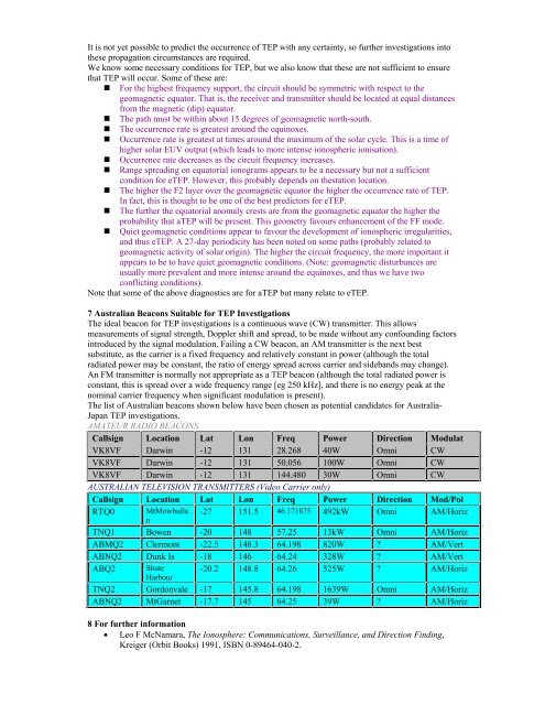
It is not yet possible to predict the occurrence of TEP with any certainty, so further investigations into<br />
these propagation circumstances are required.<br />
We know some necessary conditions for TEP, but we also know that these are not sufficient to ensure<br />
that TEP will occur. Some of these are:<br />
� For the highest frequency support, the circuit should be symmetric with respect to the<br />
geomagnetic equator. That is, the receiver <strong>and</strong> transmitter should be located at equal distances<br />
from the magnetic (dip) equator.<br />
� The path must be within about 15 degrees of geomagnetic north-south.<br />
� The occurrence rate is greatest around the equinoxes.<br />
� Occurrence rate is greatest at times around the maximum of the solar cycle. This is a time of<br />
higher solar EUV output (which leads to more intense ionospheric ionisation).<br />
� Occurrence rate decreases as the circuit frequency increases.<br />
� Range spreading on equatorial ionograms appears to be a necessary but not a sufficient<br />
condition for eTEP. However, this probably depends on thestation location.<br />
� The higher the F2 layer over the geomagnetic equator the higher the occurrence rate of TEP.<br />
In fact, this is thought to be one of the best predictors for eTEP.<br />
� The further the equatorial anomaly crests are from the geomagnetic equator the higher the<br />
probability that aTEP will be present. This geometry favours enhancement of the FF mode.<br />
� Quiet geomagnetic conditions appear to favour the development of ionospheric irregularities,<br />
<strong>and</strong> thus eTEP. A 27-day periodicity has been noted on some paths (probably related to<br />
geomagnetic activity of solar origin). The higher the circuit frequency, the more important it<br />
appears to be to have quiet geomagnetic conditions. (Note: geomagnetic disturbances are<br />
usually more prevalent <strong>and</strong> more intense around the equinoxes, <strong>and</strong> thus we have two<br />
conflicting conditions).<br />
Note that some of the above diagnostics are for aTEP but many relate to eTEP.<br />
7 Australian Beacons Suitable for TEP Investigations<br />
The ideal beacon for TEP investigations is a continuous wave (CW) transmitter. This allows<br />
measurements of signal strength, Doppler shift <strong>and</strong> spread, to be made without any confounding factors<br />
introduced by the signal modulation. Failing a CW beacon, an AM transmitter is the next best<br />
substitute, as the carrier is a fixed frequency <strong>and</strong> relatively constant in power (although the total<br />
radiated power may be constant, the ratio of energy spread across carrier <strong>and</strong> sideb<strong>and</strong>s may change).<br />
An FM transmitter is normally not appropriate as a TEP beacon (although the total radiated power is<br />
constant, this is spread over a wide frequency range [eg 250 kHz], <strong>and</strong> there is no energy peak at the<br />
nominal carrier frequency when significant modulation is present).<br />
The list of Australian beacons shown below have been chosen as potential c<strong>and</strong>idates for Australia-<br />
Japan TEP investigations.<br />
AMATEUR RADIO BEACONS<br />
Callsign Location Lat Lon Freq Power Direction Modulat<br />
VK8VF Darwin -12 131 28.268 40W Omni CW<br />
VK8VF Darwin -12 131 50.056 100W Omni CW<br />
VK8VF Darwin -12 131 144.480 30W Omni CW<br />
AUSTRALIAN TELEVISION TRANSMITTERS (Video Carrier only)<br />
Callsign Location Lat Lon Freq Power Direction Mod/Pol<br />
RTQ0 MtMowbulla<br />
n<br />
-27 151.5 46.171875 492kW Omni AM/Horiz<br />
TNQ1 Bowen -20 148 57.25 13kW Omni AM/Horiz<br />
ABMQ2 Clermont -22.5 148.3 64.198 820W ? AM/Vert<br />
ABNQ2 Dunk Is -18 146 64.24 328W ? AM/Vert<br />
ABQ2 Shute<br />
Harbour<br />
-20.2 148.8 64.26 525W ? AM/Horiz<br />
TNQ2 Gordonvale -17 145.8 64.198 1639W Omni AM/Horiz<br />
ABNQ2 MtGarnet -17.7 145 64.25 39W ? AM/Horiz<br />
8 For further information<br />
• Leo F McNamara, The Ionosphere: Communications, Surveillance, <strong>and</strong> Direction Finding,<br />
Kreiger (Orbit Books) 1991, ISBN 0-89464-040-2.