Highlander HV - Techinfo Toyota
Highlander HV - Techinfo Toyota
Highlander HV - Techinfo Toyota

You also want an ePaper? Increase the reach of your titles
YUMPU automatically turns print PDFs into web optimized ePapers that Google loves.
© 2010 <strong>Toyota</strong> Motor Corporation<br />
All rights reserved. This document may not be<br />
altered without the written permission of <strong>Toyota</strong> Motor Corporation.<br />
08 <strong>Highlander</strong> ERG REV B (12/26/12)<br />
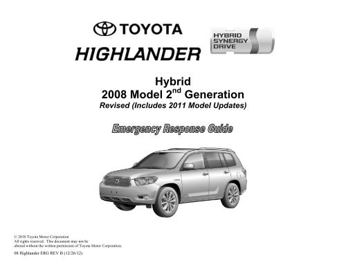
Hybrid<br />
2008 Model 2 nd Generation<br />
Revised (Includes 2011 Model Updates)
Foreword<br />
The 2 nd generation <strong>Toyota</strong> <strong>Highlander</strong> gasoline-electric hybrid<br />
Emergency Response Guide has been revised to include the changes of<br />
the 2011 model year vehicle. These changes include minor updates to<br />
the gasoline engine, vehicle exterior and interior. The important change<br />
affecting the emergency responder is the relocation of the 12 Volt<br />
auxiliary battery from the engine compartment to the rear cargo area.<br />
The 2 nd generation <strong>Highlander</strong> hybrid introduced in May 2007<br />
continues to share the basic vehicle systems and features of the<br />
conventional, non-hybrid, <strong>Highlander</strong>.<br />
High voltage electricity powers the electric motors, generator, A/C<br />
compressor, and inverter/converter. All other automotive electrical<br />
devices such as the headlights, radio, and gauges are powered from a<br />
separate 12 Volt auxiliary battery. Numerous safeguards have been<br />
designed into the <strong>Highlander</strong> hybrid to help ensure the high voltage,<br />
approximately 288 Volt, Nickel Metal Hydride (NiMH) Hybrid Vehicle<br />
(<strong>HV</strong>) battery pack is kept safe and secure in an accident.<br />
The <strong>Highlander</strong> hybrid utilizes the following electrical systems:<br />
Maximum 650 Volts AC<br />
Nominal 288 Volts DC<br />
Nominal 12 Volts DC<br />
2 nd Generation <strong>Highlander</strong> Hybrid Features:<br />
Complete model change with a new exterior and interior design.<br />
Smart key and mechanical ignition key systems available.<br />
A boost converter in the inverter/converter that boosts to 650 Volts<br />
the available voltage to the electric motors.<br />
A high voltage Hybrid Vehicle (<strong>HV</strong>) battery pack rated at 288 Volts.<br />
High voltage motor driven Air Conditioning (A/C) compressor<br />
rated at 288 Volts.<br />
A body electrical system rated at 12 Volts, negative chassis ground.<br />
Standard four-wheel-drive intelligent (4WD-i) with front and rear<br />
650 Volt electric motors.<br />
Supplemental Restraint System (SRS) – dual stage frontal airbags,<br />
front seat mounted side airbags, side curtain airbags, front seatbelt<br />
pretensioners, and a driver side knee airbag.<br />
-i-<br />
High voltage electrical safety remains an important factor in the<br />
emergency handling of the <strong>Highlander</strong> Hybrid Synergy Drive. It is<br />
important to recognize and understand the disabling procedures and<br />
warnings throughout the guide.<br />
Additional topics in the guide include:<br />
<strong>Toyota</strong> <strong>Highlander</strong> hybrid identification.<br />
Major Hybrid Synergy Drive component locations and descriptions.<br />
Extrication, fire, recovery, and additional emergency response<br />
information.<br />
Roadside assistance information.<br />
2011 Model Year<br />
<strong>Highlander</strong> Hybrid<br />
(2 nd Generation Updated)<br />
2008 – 2010 Model Year<br />
<strong>Highlander</strong> Hybrid<br />
(2 nd Generation)<br />
This guide is intended to assist emergency responders in the safe<br />
handling of a <strong>Toyota</strong> <strong>Highlander</strong> hybrid vehicle during an incident.<br />
NOTE:<br />
Emergency Response Guides for <strong>Toyota</strong> hybrid and alternative fuel<br />
vehicles may be viewed at http://techinfo.toyota.com.
Table of Contents Page<br />
About the <strong>Highlander</strong> Hybrid 1<br />
<strong>Highlander</strong> Hybrid Identification 2<br />
Hybrid Synergy Drive Component Locations & Descriptions 6<br />
Smart Key System (Optional Equipment) 9<br />
Hybrid Synergy Drive Operation 13<br />
Hybrid Vehicle (<strong>HV</strong>) Battery Pack 14<br />
Low Voltage Battery 15<br />
High Voltage Safety 16<br />
SRS Airbags & Seat Belt Pretensioners 17<br />
Emergency Response 19<br />
Extrication 19<br />
Fire 27<br />
Overhaul 28<br />
Recovering/Recycling of NiMH <strong>HV</strong> Battery Pack 28<br />
Spills 29<br />
First Aid 29<br />
Submersion 30<br />
Roadside Assistance 31<br />
-ii-
About the <strong>Highlander</strong> Hybrid<br />
The <strong>Highlander</strong> hybrid continues into its 2 nd generation as a gasolineelectric<br />
hybrid vehicle. Hybrid Synergy Drive means that the vehicle<br />
contains a gasoline engine and electric motors for power. The two<br />
hybrid power sources are stored on board the vehicle:<br />
1. Gasoline stored in the fuel tank for the gasoline engine.<br />
2. Electricity stored in a high voltage Hybrid Vehicle (<strong>HV</strong>) battery pack<br />
for the electric motors.<br />
The result of combining these two power sources is improved fuel<br />
economy and reduced emissions. The gasoline engine also powers an<br />
electric generator to recharge the battery pack; unlike a pure all electric<br />
vehicle, the <strong>Highlander</strong> hybrid never needs to be recharged from an<br />
external electric power source.<br />
Depending on the driving conditions one or both sources are used to<br />
power the vehicle. The following illustration demonstrates how the<br />
<strong>Highlander</strong> hybrid operates in various driving modes.<br />
During light acceleration at low speeds, the vehicle is powered by<br />
the electric motors. The gasoline engine is shut off.<br />
During normal driving, the vehicle is powered mainly by the<br />
gasoline engine. The gasoline engine also powers the generator to<br />
recharge the battery pack.<br />
-1-<br />
During full acceleration, such as climbing a hill, both the gasoline<br />
engine and the electric motor power the vehicle.<br />
During deceleration, such as when braking, the vehicle regenerates<br />
the kinetic energy from the wheels to produce electricity that<br />
recharges the battery pack.<br />
While the vehicle is stopped, the gasoline engine and electric<br />
motors are off, however the vehicle remains on and operational.
<strong>Highlander</strong> Hybrid Identification<br />
In appearance, the 2011 model year <strong>Highlander</strong> hybrid is nearly identical<br />
to the conventional, non-hybrid <strong>Toyota</strong> <strong>Highlander</strong>. The <strong>Highlander</strong><br />
hybrid is a 5-door SUV. Exterior, interior, and engine compartment<br />
illustrations are provided to assist in identification.<br />
The alphanumeric 17 character Vehicle Identification Number (VIN) is<br />
provided in the front windshield cowl and driver door pillar.<br />
Example VIN: JTEEW41AF82020211 (2008 - 2010 Models)<br />
JTEBC3EHF82020211 (2011 Model)<br />
JTEBD3EHF82020211 (2011 Model)<br />
A <strong>Highlander</strong> hybrid is identified by the first 6 alphanumeric characters<br />
JTEEW4, JTEBC3 or JTEBD3.<br />
-2-<br />
Driver Side Windshield Driver Side B Pillar
<strong>Highlander</strong> Hybrid Identification (Continued)<br />
Exterior<br />
logo on the back door.<br />
<strong>Highlander</strong> logo on the back door panel garnish.<br />
logo on each front fender.<br />
Gasoline fuel filler door located on the driver side rear quarter panel.<br />
A radiator grill that is unique to the hybrid model.<br />
<br />
2008 –2010 Exterior Driver Side View<br />
2008 –2010 Exterior Front View 2008 –2010 Exterior Rear View<br />
<br />
<br />
<br />
<br />
<br />
<br />
<br />
<br />
2008 –2010 Exterior Rear and Driver Side View<br />
<br />
-3-<br />
<br />
<br />
2011 Exterior Driver Side View<br />
2011 Exterior Front View 2011 Exterior Rear View<br />
<br />
<br />
<br />
<br />
<br />
2011 Exterior Rear and Driver Side View
<strong>Highlander</strong> Hybrid Identification (Continued)<br />
Interior<br />
<strong>Highlander</strong> Hybrid front door sill/scuff plate. (Standard on 2008 - 2010<br />
Models and optional on 2011 Model)<br />
The instrument cluster (speedometer, fuel gauge, warning lights) located in<br />
the dash behind the steering wheel, is different than the one on the<br />
conventional, non-hybrid <strong>Highlander</strong>.<br />
In place of a tachometer, a power meter showing kW output is used.<br />
NOTE:<br />
If the vehicle is shut off, the instrument cluster gauges will be “blacked<br />
out”, not illuminated.<br />
-4-<br />
<br />
<br />
<br />
Interior View of Front Door Sill/Scuff Plate<br />
<br />
Instrument Cluster View
<strong>Highlander</strong> Hybrid Identification (Continued)<br />
Engine Compartment<br />
3.3-liter aluminum alloy gasoline engine. (2008 - 2010 Models)<br />
3.5-liter aluminum alloy gasoline engine. (2011 Model)<br />
High voltage inverter/converter assembly with logo on the cover.<br />
(2008 - 2010 Models)<br />
3.5-liter aluminum alloy gasoline engine with logo on the cover.<br />
(2011 Model)<br />
-5-<br />
<br />
<br />
Engine Compartment View (2008 – 2010 Models)<br />
<br />
<br />
Engine Compartment View (2011 Model)
Hybrid Synergy Drive Component Locations &<br />
Descriptions<br />
Component Location Description<br />
12 Volt <br />
Auxiliary<br />
Battery<br />
Hybrid <br />
Vehicle<br />
(<strong>HV</strong>)<br />
Battery<br />
Pack<br />
Power <br />
Cables<br />
Inverter/<br />
Converter<br />
<br />
Gasoline <br />
Engine<br />
Front<br />
Electric<br />
Motor<br />
Electric <br />
Generator<br />
Engine Compartment<br />
(2008 - 2010 Models)<br />
Cargo Area (2011<br />
Model)<br />
Cabin Area, Mounted<br />
to Cross Member<br />
under Second Row<br />
Seat<br />
Undercarriage and<br />
Engine Compartment<br />
A lead-acid battery that supplies power to<br />
the low voltage devices.<br />
288 Volt Nickel Metal Hydride (NiMH)<br />
battery pack consisting of 30 low voltage<br />
(9.6 Volt) modules connected in series.<br />
Orange colored power cables carry high<br />
voltage Direct Current (DC) between the<br />
<strong>HV</strong> battery pack, inverter/converter, and<br />
A/C compressor. These cables also carry<br />
3-phase Alternating Current (AC)<br />
between the inverter/converter, electric<br />
motors, and generator.<br />
Engine Compartment Boosts and inverts the high voltage<br />
electricity from the <strong>HV</strong> battery pack to 3phase<br />
AC electricity that drives the<br />
electric motors. The inverter/converter<br />
also converts AC electricity from the<br />
electric generator and electric motors<br />
(regenerative braking) to DC that<br />
recharges the <strong>HV</strong> battery pack.<br />
Engine Compartment Provides two functions:<br />
1) Powers vehicle.<br />
2) Powers generator to recharge the <strong>HV</strong><br />
battery pack.<br />
The engine is started and stopped under<br />
control of the vehicle computer.<br />
Engine Compartment 3-phase high voltage AC permanent<br />
magnet electric motor contained in the<br />
front transaxle. It is used to power the<br />
front wheels.<br />
Engine Compartment 3-phase high voltage AC generator that is<br />
contained in the transaxle and recharges<br />
the <strong>HV</strong> battery pack.<br />
-6-<br />
<br />
<br />
<br />
<br />
<br />
Hybrid Synergy Drive Components (2008 - 2010 Models)<br />
<br />
<br />
<br />
<br />
<br />
<br />
<br />
<br />
<br />
Hybrid Synergy Drive Components (2011 Model)
Hybrid Synergy Drive Component Locations &<br />
Descriptions (Continued)<br />
Component Location Description<br />
A/C<br />
Compressor<br />
(with<br />
Inverter) <br />
Fuel Tank<br />
and Fuel Line<br />
<br />
Rear Electric<br />
Motor <br />
Engine<br />
Compartment<br />
Undercarriage<br />
and Center<br />
3-phase high voltage AC electrically driven<br />
motor compressor.<br />
The fuel tank provides gasoline via a fuel<br />
line to the engine. The fuel line is routed<br />
under the center of vehicle.<br />
Rear Sub-Frame 3-phase high voltage AC permanent magnet<br />
electric motor contained in the rear<br />
transaxle. It is used to power the rear<br />
wheels.<br />
-7-<br />
2008 - 2010 Models<br />
<br />
<br />
<br />
<br />
<br />
<br />
<br />
Components (Top View) and High Voltage Power Cables<br />
<br />
<br />
Fuel Tank and Fuel Line (2008 - 2010 Models)<br />
<br />
<br />
Fuel Tank and Fuel Line (2011 Model)<br />
<br />
2011 Model
Hybrid Synergy Drive Component Locations &<br />
Descriptions (Continued)<br />
Key Specifications:<br />
Gasoline Engine: 208 hp (156 kW), 3.3-liter Aluminum Alloy Engine<br />
(2008 - 2010 Models)<br />
231 hp (172 kW), 3.5-liter Aluminum Alloy Engine<br />
(2011 Model)<br />
Electric Motors<br />
Front:<br />
Rear:<br />
165 hp (123 kW), Permanent Magnet Motor<br />
67 hp (50 kW), Permanent Magnet Motor<br />
Transmission: Automatic Only (electrically controlled continuously<br />
variable transaxle)<br />
<strong>HV</strong> Battery: 288 Volt Sealed NiMH Battery<br />
Curb Weight: 4,641 lbs/2,105 kg (2008 - 2010 Models)<br />
4,762 lbs/2,160 kg (2011 Model)<br />
Fuel Tank: 17.2 gals/65.0 liters<br />
Fuel Economy<br />
Ratings:<br />
27/25 (City/Hwy) miles/gal (2008 - 2010 Models)<br />
28/28 (City/Hwy) miles/gal (2011 Model)<br />
8.6/9.4 (City/Hwy) liters/100 km (2008 - 2010 Models)<br />
6.6/7.3 (City/Hwy) liters/100 km (2011 Model)<br />
Frame Material: Steel Unibody<br />
Body Material: Steel Panels<br />
Seating Capacity: 5 passenger/7 passenger with optional 3rd row seating<br />
(2008 - 2010 Models)<br />
7 passenger with standard 3rd row seating<br />
(2011 Model)<br />
-8-<br />
Steel Unibody
Smart Key System (Optional Equipment)<br />
The <strong>Highlander</strong> hybrid smart key system, which is standard on 2008 -<br />
2010 models and optional on the 2011 model, consists of a smart key<br />
transceiver that communicates bi-directionally, enabling the vehicle to<br />
recognize the smart key in proximity to the vehicle. Once recognized,<br />
the smart key will allow the user to lock and unlock the doors without<br />
pushing smart key buttons, and start the vehicle without inserting it into<br />
an ignition switch.<br />
Smart key features:<br />
Passive (remote) function to lock/unlock the doors, unlock the<br />
optional glass hatch/power back door, and start the vehicle.<br />
Wireless transmitter buttons to lock/unlock all 5 doors.<br />
A wireless transmitter button to operate the optional power back door<br />
opener.<br />
Hidden metal cut key to lock/unlock the doors.<br />
Door (Lock/Unlock)<br />
There are several methods available to lock/unlock the doors.<br />
Pushing the smart key lock/unlock buttons will lock/unlock all doors<br />
including the back door.<br />
Touching the sensor on the backside of the driver door exterior handle, with<br />
the smart key in proximity to the vehicle, unlocks the driver door. Touching<br />
the sensor on the backside of the passenger door exterior handle, with the<br />
smart key in proximity to the vehicle, unlocks all doors. Pushing the lock<br />
button on either front door, or the back door will lock all doors.<br />
Inserting the hidden metal cut key in the driver door lock and turning<br />
clockwise once unlocks the driver door, twice unlocks all doors. To lock<br />
all doors turn the key counter clockwise once. Only the driver door<br />
contains an exterior door lock for the metal cut key.<br />
-9-<br />
Unlock Touch<br />
Sensor<br />
Smart Key Hidden Metal Cut Key for Door Lock<br />
Lock<br />
Button<br />
Driver Door Unlock Touch Sensor and<br />
Lock Button<br />
Release Button<br />
Use the Hidden Metal Cut Key<br />
Front Driver Door Lock
Smart Key System (Optional Equipment - Continued)<br />
Back Door (Lock/Unlock)<br />
Using the following methods will lock/unlock back door.<br />
Pushing<br />
door.<br />
on the wireless smart key locks all doors, including the back<br />
Pushing the back door lock button (see illustration) will lock all doors,<br />
including the back door.<br />
Pushing on the wireless smart key twice unlocks all doors, including the<br />
<br />
back door.<br />
Touching the back door opener switch (see illustration) with the smart key<br />
in proximity to the back door will unlock/open the back door.<br />
Optional Power Back Door (Open/Close)<br />
Various methods are available to open/close the optional power back door.<br />
Pushing and holding on the wireless smart key will open/close the<br />
optional power back door.<br />
Pushing the power back door switch on the instrument panel will<br />
open/close the power back door.<br />
Pushing the power back door closer switch (see illustration) located on the<br />
bottom of the door will close the power door.<br />
NOTE:<br />
If the power back door cancel switch is activated the power back door will not<br />
function.<br />
-10-<br />
Wireless<br />
Smart Key<br />
Back Door<br />
Opener Switch<br />
Back Door Lock Button and Opener Switch<br />
Optional Power Back<br />
Door Closer Switch Optional Power<br />
Back Door Switch<br />
Power Back Door Cancel Switch<br />
Optional Power Back Door Switches<br />
Power Back Door<br />
Cancel Switch<br />
Back Door<br />
Lock Button
Smart Key System (Optional Equipment - Continued)<br />
Optional Glass Hatch (Unlock/Open)<br />
The optional glass hatch can be unlocked/opened two ways:<br />
1. When the vehicle is unlocked, pushing the glass hatch opener button<br />
(see illustration) on the back door will open the glass hatch.<br />
2. When the vehicle is locked, with the smart key in proximity to the<br />
back door, pushing the glass hatch opener button once will unlock<br />
and open the glass hatch.<br />
-11-<br />
Glass Hatch Opener Button<br />
Glass Hatch Opener Button
Smart Key System (Optional Equipment - Continued)<br />
Vehicle Starting/Stopping<br />
The smart key has replaced the conventional metal cut key, and the power<br />
button with an integral status indicator light has replaced the ignition switch.<br />
The smart key only needs to be in proximity to the vehicle to allow the system<br />
to function.<br />
With the brake pedal released, the first push of the power button operates<br />
the accessory mode, the second push operates the ignition-on mode, and the<br />
third push turns the ignition off again.<br />
Ignition Mode Sequence (brake pedal released):<br />
Vehicle Off Accessory Ignition-On<br />
Button Push Button Push<br />
Button Push<br />
Starting the vehicle takes priority over all other ignition modes and is<br />
accomplished by depressing the brake pedal and pushing the power button<br />
once. To verify the vehicle has started, check that the power button status<br />
indicator light is off and the READY light is illuminated in the instrument<br />
cluster.<br />
If the internal smart key battery is dead, use the following method to start<br />
the vehicle.<br />
1. Touch the <strong>Toyota</strong> emblem side of the smart key to the power button.<br />
2. Within the 5 seconds after the buzzer sounds, push the power button<br />
with the brake pedal depressed (the READY light will illuminate).<br />
Once the vehicle has started and is on and operational (READY-ON), the<br />
vehicle is shut off by bringing the vehicle to a complete stop, placing the<br />
gearshift lever in park (P), and then depressing the power button once.<br />
To shut off the vehicle before coming to a stop in an emergency, push and<br />
hold down the power button for more than 3 seconds. This procedure may<br />
be useful such as at an accident scene in which the READY indicator is on<br />
and the drive wheels remain in motion.<br />
-12-<br />
Ignition Mode Power Button Indicator Light<br />
Off Off<br />
Accessory Amber<br />
Ignition-On Amber<br />
Brake Pedal Depressed Green<br />
Vehicle Started (READY-ON) Off<br />
Malfunction Blinking Amber<br />
Power Button with Integral Status<br />
Indicator Light<br />
Starting Sequence<br />
(Brake Pedal Depressed)<br />
Ignition Modes (Brake Pedal Released)<br />
Smart Key Recognition<br />
(When Smart Key Battery is Dead)
Hybrid Synergy Drive Operation<br />
Once the READY indicator is illuminated in the instrument cluster, the<br />
vehicle may be driven. However, the gasoline engine does not idle like a<br />
typical automobile and will start and stop automatically. It is important<br />
to recognize and understand the READY indicator provided in the<br />
instrument cluster. When lit, it informs the driver that the vehicle is on<br />
and operational even though the gasoline engine may be off and the<br />
engine compartment is silent.<br />
Vehicle Operation<br />
With the <strong>Highlander</strong> hybrid, the gasoline engine may stop and start at any<br />
time while the READY indicator is on.<br />
Never assume that the vehicle is shut off just because the engine is off.<br />
Always look for the READY indicator status. The vehicle is shut off when<br />
the READY indicator is off.<br />
The vehicle may be powered by:<br />
1. The electric motors only.<br />
2. The gasoline engine only.<br />
3. A combination of both the electric motors and the gasoline engine.<br />
The vehicle computer determines the mode in which the vehicle operates in<br />
order to improve fuel economy and reduce emissions. Two new features on<br />
the 2008 <strong>Highlander</strong> hybrid are EV (Electric Vehicle) drive mode and<br />
ECON (Economy) drive mode:<br />
1. EV Drive Mode: When activated, and certain conditions have<br />
been met, the vehicle operates with the electric motor powered by<br />
the <strong>HV</strong> battery.<br />
2. Economy Drive Mode: When activated, this mode helps enhance<br />
fuel economy on trips that involve frequent braking and<br />
acceleration.<br />
-13-<br />
Instrument Cluster READY Indicator<br />
Economy Drive<br />
Mode Switch<br />
EV Drive Mode<br />
Switch<br />
EV Drive Mode Switch/Economy Drive Mode Switch
Hybrid Vehicle (<strong>HV</strong>) Battery Pack<br />
The <strong>Highlander</strong> hybrid features a high voltage Hybrid Vehicle (<strong>HV</strong>)<br />
battery pack that contains sealed Nickel Metal Hydride (NiMH) battery<br />
modules.<br />
<strong>HV</strong> Battery Pack<br />
The <strong>HV</strong> battery pack is enclosed in a metal case and is rigidly mounted to<br />
the cabin area floor pan cross member under the second row rear seat. The<br />
metal case is isolated from high voltage and concealed by carpet in the<br />
cabin area.<br />
The <strong>HV</strong> battery pack consists of 30 low voltage (9.6 Volt) NiMH battery<br />
modules connected in series to produce approximately 288 Volts. Each<br />
NiMH battery module is non-spillable and sealed in a metal case.<br />
The electrolyte used in the NiMH battery module is an alkaline mixture of<br />
potassium and sodium hydroxide. The electrolyte is absorbed into the<br />
battery cell plates and will not normally leak, even in a collision.<br />
In the unlikely event that the battery pack is overcharged, the modules vent<br />
gases directly outside the vehicle through a vent hose.<br />
<strong>HV</strong> Battery Pack<br />
Battery pack voltage 288 V<br />
Number of NiMH battery modules in the pack 30<br />
NiMH battery module voltage 9.6 V<br />
NiMH battery module dimensions 1 x 15 x 3.3 in<br />
(18.5 x 382 x 86 mm)<br />
NiMH module weight 3.3 lbs (1.5 kg)<br />
NiMH battery pack dimensions 25 x 43 x 7 in<br />
(630 x 1080 x 180 mm)<br />
NiMH battery pack weight 152.1 lbs<br />
(69 kg)<br />
-14-<br />
Components Powered by the <strong>HV</strong> Battery Pack<br />
Front Electric Motor Rear Electric Motor<br />
Inverter/Converter Power Cables<br />
A/C Compressor Electric Generator<br />
<strong>HV</strong> Battery Pack Recycling<br />
The <strong>HV</strong> battery pack is recyclable. Contact the nearest <strong>Toyota</strong> dealer or:<br />
United States: (800) 331-4331<br />
Canada: (888) TOYOTA 8 [(888) 869-6828]<br />
<strong>HV</strong> Battery Pack
Low Voltage Battery<br />
Auxiliary Battery<br />
The <strong>Highlander</strong> hybrid contains a lead-acid 12 Volt auxiliary battery. The<br />
12 Volt auxiliary battery powers the vehicle’s electrical system similar to a<br />
conventional vehicle. As with conventional vehicles, the negative terminal<br />
of the auxiliary battery is grounded to the metal chassis of the vehicle.<br />
For 2008 - 2010 models, the auxiliary battery is located in the engine<br />
compartment.<br />
For the 2011 model, the auxiliary battery is located in the cargo area. It is<br />
concealed by a battery cover on the driver side of the vehicle.<br />
NOTE:<br />
An under hood label shows the location of the <strong>HV</strong> battery (traction battery)<br />
and 12 Volt auxiliary battery.<br />
-15-<br />
12 Volt Auxiliary Battery Mounted in<br />
Engine Compartment<br />
(2008 - 2010 Models)<br />
Battery Location Label<br />
12 Volt Auxiliary Battery Mounted in<br />
Cargo Area (2011 Model)<br />
2008 – 2010 Models 2011 Model
High Voltage Safety<br />
The <strong>HV</strong> battery pack powers the high voltage electrical system with DC<br />
electricity. Positive and negative orange colored high voltage power cables are<br />
routed from the battery pack, under the vehicle floor pan, to the<br />
inverter/converter. The inverter/converter contains a circuit that boosts the <strong>HV</strong><br />
battery voltage from 288 to 650 Volts DC. The inverter/converter creates 3phase<br />
AC to power the motors. Power cables are routed from the<br />
inverter/converter to each high voltage motor (front and rear electric motors,<br />
electric generator, and A/C compressor). The following systems are intended to<br />
help keep occupants in the vehicle and emergency responders safe from high<br />
voltage electricity:<br />
High Voltage Safety System<br />
A high voltage fuse provides short circuit protection in the <strong>HV</strong> battery<br />
pack.<br />
Positive and negative high voltage power cables connected to the <strong>HV</strong><br />
battery pack are controlled by 12 Volt normally open relays . When the<br />
vehicle is shut off, the relays stop electrical flow from leaving the <strong>HV</strong><br />
battery pack.<br />
WARNING:<br />
The high voltage system may remain powered for up to 10 minutes after<br />
the vehicle is shut off or disabled. To prevent serious injury or death<br />
from severe burns or electric shock, avoid touching, cutting, or<br />
breaching any orange high voltage power cable or high voltage<br />
component.<br />
Both positive and negative power cables are insulated from the metal<br />
body. High voltage electricity flows through these cables and not through<br />
the metal vehicle body. The metal vehicle body is safe to touch because it<br />
is insulated from the high voltage components.<br />
A ground fault monitor continuously monitors for high voltage leakage<br />
to the metal chassis while the vehicle is running. If a malfunction is<br />
detected, the hybrid vehicle computer will illuminate the master warning<br />
light in the instrument cluster and indicate “Check Hybrid System” on<br />
the multi-information display.<br />
-16-<br />
2008 – 2010 Models 2011 Model<br />
12 Volt Auxiliary<br />
Battery<br />
A/C<br />
Compressor<br />
Electric<br />
Generator<br />
Electric<br />
Motor<br />
<br />
High Voltage Safety System – Vehicle Shut Off (READY-OFF)<br />
2008 – 2010 Models<br />
12 Volt Auxiliary<br />
Battery<br />
A/C<br />
Compressor<br />
Electric<br />
Generator<br />
Electric<br />
Motor<br />
AC<br />
3-Phase<br />
AC<br />
3-Phase<br />
00<br />
Volt DC<br />
288<br />
Volt DC<br />
Inverter/<br />
Converter<br />
Inverter/<br />
Converter<br />
High Voltage Safety System – Vehicle On and Operational (READY-ON)<br />
<br />
Hybrid Vehicle Computer<br />
00<br />
Volt DC<br />
<br />
Hybrid Vehicle Computer<br />
288<br />
Volt DC<br />
<br />
<br />
<br />
<strong>HV</strong> Battery Pack<br />
<strong>HV</strong> Battery Pack<br />
12 Volt Auxiliary<br />
Battery<br />
Electric<br />
Motor<br />
(Rear)<br />
2011 Model<br />
12 Volt Auxiliary<br />
Battery<br />
Electric<br />
Motor<br />
(Rear)
SRS Airbags & Seat Belt Pretensioners<br />
Standard Equipment<br />
Electronic frontal impact sensors (2) are mounted in the engine<br />
compartment as illustrated.<br />
Front seat belt pretensioners are mounted near the base of the B-pillars .<br />
A frontal dual stage driver airbag is mounted in the steering wheel hub.<br />
A frontal dual stage passenger airbag is integrated into the dashboard<br />
and deploys through the dashboard.<br />
The SRS computer , which contains an impact sensor, is mounted on the<br />
floor pan underneath the instrument panel, forward of the shift lever.<br />
Front electronic side impact sensors (2) are mounted near the base of the Bpillars<br />
.<br />
Rear electronic side impact sensors (2) are mounted near the base of the Cpillars<br />
.<br />
Front seat side airbags are mounted in the seatbacks.<br />
Side curtain airbags are mounted along the outer edge inside the roof<br />
rails.<br />
A front knee airbag is mounted on the driver side lower portion of the<br />
dash.<br />
Front door electronic side impact sensors (2) are mounted inside the base of<br />
the front doors (2011 Model).<br />
Active (mechanical non-pyrotechnic) front seat headrests (see description<br />
on page 26).<br />
WARNING:<br />
The SRS may remain powered for up to 90 seconds after the vehicle is<br />
shut off or disabled. To prevent serious injury or death from<br />
unintentional SRS deployment, avoid breaching the SRS components.<br />
-17-<br />
<br />
<br />
<br />
<br />
Electronic Impact Sensors and Front Seat Side Airbags<br />
<br />
<br />
<br />
<br />
Standard Frontal Airbags, Seat Belt Pretensioners, Knee Airbag, Side Curtain<br />
Airbags<br />
<br />
<br />
<br />
<br />
<br />
Side Curtain Airbag<br />
Inflators
SRS Airbags & Seat Belt Pretensioners (Continued)<br />
Standard Equipment (Continued)<br />
NOTE:<br />
The front seatback mounted side airbags and the side curtain airbags may<br />
deploy independently of each other.<br />
The knee airbag (driver side only) deploys simultaneously with the frontal<br />
airbags and seat belt pretensioners.<br />
The <strong>Highlander</strong> hybrid is equipped with a standard front passenger<br />
occupant classification system that may prohibit the deployment of the<br />
front passenger frontal airbag, seatback mounted side airbag, and seat belt<br />
pretensioner. If the passenger occupant classification system prohibits<br />
deployment during an SRS event, the passenger SRS will not re-arm nor<br />
deploy.<br />
Beginning with the 2011 model, an electronic side impact sensor, installed<br />
in each front door, has been added to the SRS airbag system to aid in side<br />
collision detection accuracy.<br />
SRS System Diagram (2008 - 2010 Models)<br />
-18-<br />
SRS System Diagram (2011 Model)<br />
Frontal, Knee, Front Seatback Mounted Side, Side Curtain Airbags.<br />
Driver Knee Airbag and Inflator
Emergency Response<br />
On arrival, emergency responders should follow their standard<br />
operating procedures for vehicle incidents. Emergencies involving the<br />
<strong>Highlander</strong> hybrid may be handled like other automobiles except as<br />
noted in these guidelines for Extrication, Fire, Overhaul, Recovery,<br />
Spills, First Aid, and Submersion.<br />
WARNING:<br />
Never assume the <strong>Highlander</strong> hybrid is shut off simply because it<br />
is silent.<br />
Always observe the instrument cluster for the READY indicator<br />
status to verify whether the vehicle is on or shut off. The vehicle is<br />
shut off when the READY indicator is off.<br />
Failure to shut off the vehicle before emergency response<br />
procedures are performed may result in serious injury or death<br />
from the unintentional deployment of the SRS or severe burns and<br />
electric shock from the high voltage electrical system.<br />
Extrication<br />
Immobilize Vehicle<br />
Chock wheels and set the parking brake.<br />
Move the shift lever to park (P).<br />
Disable Vehicle<br />
Performing either of the following two procedures will shut the<br />
vehicle off and disable the <strong>HV</strong> battery pack, SRS, and gasoline fuel<br />
pump.<br />
-19-<br />
Chock Wheels Set Parking Brake<br />
Shift Lever in Park (P)
Emergency Response (Continued)<br />
Extrication (Continued)<br />
Procedure #1<br />
Smart Key System:<br />
(Standard on 2008 - 2010 Models & Optional on 2011<br />
Model)<br />
1. Confirm the status of the READY indicator in the instrument<br />
cluster.<br />
2. If the READY indicator is illuminated, the vehicle is on and<br />
operational. Shut off the vehicle by pushing the power button<br />
once.<br />
3. The vehicle is already shut off if the instrument cluster lights and<br />
the READY indicator are not illuminated. Do not push the<br />
power button because the vehicle may start.<br />
4. If the smart key is easily accessible, keep it at least 16 feet (5<br />
meters) away from the vehicle.<br />
5. If the smart key cannot be found, disconnect the 12 Volt<br />
auxiliary battery to prevent accidental restarting of the vehicle.<br />
Auxiliary battery location:<br />
Engine compartment (2008 - 2010 Models)<br />
Cargo area (2011 Model)<br />
-20-<br />
Shut Off Vehicle (READY-OFF) Remote Hood Release<br />
Hood Latch Release<br />
Back Door<br />
Opener Switch<br />
Back Door Opener Switch<br />
Volt Auxiliary Battery in Engine<br />
Compartment (2008 - 2010 Models)<br />
12 Volt Auxiliary Battery in Cargo<br />
Area (2011 Model)
Emergency Response (Continued)<br />
Extrication (Continued)<br />
Mechanical Ignition Key System:<br />
(Standard on 2011 Model)<br />
1. Confirm the status of the READY indicator in the instrument<br />
cluster.<br />
2. If the READY indicator is illuminated, the vehicle is on and<br />
operational. Shut off the vehicle by turning the ignition key off,<br />
removing the ignition key and placing it on the dash.<br />
3. Disconnect the 12 Volt auxiliary battery in the cargo area to<br />
prevent accidental restarting of the vehicle.<br />
-21-<br />
Turn Ignition Key Off Back Door Opener Switch<br />
12 Volt Auxiliary Battery in Cargo<br />
Area (2011 Model)<br />
Back Door<br />
Opener Switch
Emergency Response (Continued)<br />
Extrication (Continued)<br />
Procedure #2 (Alternate if power button or ignition key is<br />
inaccessible)<br />
1. Remove the fuse box cover.<br />
2. Remove the appropriate fuse in the engine compartment fuse box<br />
as illustrated.<br />
30A green IGCT fuse (2008 - 2010 Models)<br />
30A green IG2 fuse (2011 Model)<br />
If the correct fuse cannot be recognized, pull all fuses in the fuse<br />
box.<br />
3. Disconnect the 12 Volt auxiliary battery.<br />
Auxiliary battery location:<br />
Engine compartment (2008 - 2010 Models)<br />
Cargo area (2011 Model)<br />
NOTE:<br />
Before disconnecting the 12 Volt auxiliary battery, if necessary,<br />
reposition the power seats, lower the windows, unlock the doors,<br />
open the back door and the fuel door as required. A manual fuel door<br />
release is located behind a panel in the driver side of the cargo area<br />
(see the illustration in the Roadside Assistance section on page 32).<br />
Once the 12 Volt auxiliary battery is disconnected, power controls<br />
will not operate.<br />
WARNING:<br />
The high voltage system may remain powered for up to 10 minutes<br />
after the vehicle is shut off or disabled. To prevent serious injury or<br />
death from severe burns or electric shock, avoid touching, cutting, or<br />
breaching any orange high voltage power cable or high voltage<br />
component.<br />
The SRS may remain powered for up to 90 seconds after the vehicle is<br />
shut off or disabled. To prevent serious injury or death from<br />
unintentional SRS deployment, avoid breaching the SRS components.<br />
If none of the disabling procedures can be performed, proceed with<br />
caution as there is no assurance that the high voltage electrical system,<br />
SRS, or fuel pump are disabled.<br />
-22-<br />
12 Volt Auxiliary<br />
Battery<br />
IGCT Fuse (30A green)<br />
Remove Fuse Box Cover (2008 - 2010 Models)<br />
2011 Remove Fuse Box Cover (2011 Model)<br />
IGCT Fuse Location in Engine<br />
Compartment Fuse Box<br />
(2008 - 2010 Models)<br />
Fuse Box<br />
Fuse Box<br />
IG2 fuse (30A Green)<br />
IG2 Fuse Location in Engine<br />
Compartment Fuse Box (2011 Model)
Emergency Response (Continued)<br />
Extrication (Continued)<br />
Stabilize Vehicle<br />
Crib at (4) points directly under the front and rear pillars.<br />
Do not place cribbing under the high voltage power cables, exhaust<br />
system, or fuel system.<br />
NOTE:<br />
The <strong>Highlander</strong> hybrid is equipped with a tire pressure warning<br />
system that by design prevents pulling the metal valve stem with<br />
integral transmitter from the wheel. Snapping the valve stem with<br />
pliers or removing the valve cap and Schrader valve will release the<br />
air in the tire.<br />
Access Patients<br />
Glass Removal<br />
Use normal glass removal procedures as required.<br />
SRS Awareness<br />
Responders need to be cautious when working in close proximity<br />
to undeployed airbags and seat belt pretensioners. Front dual<br />
stage airbags automatically ignite both stages within a fraction of<br />
a second.<br />
Door Removal/Displacement<br />
Doors can be removed by conventional rescue tools such as hand,<br />
electric, and hydraulic tools. In certain situations, it may be<br />
easier to pry back the vehicle body to expose and unbolt the<br />
hinges.<br />
NOTE:<br />
Beginning with the 2011 model, the <strong>Highlander</strong> hybrid is<br />
equipped with an electronic impact sensor mounted in both front<br />
doors. During door removal, cutting the wiring harness routed to<br />
the front door will not result in airbag deployment.<br />
-23-<br />
Cribbing Points<br />
Cribbing Points<br />
Tire Pressure Sensor Metal Valve Stem<br />
with Integral Transmitter<br />
Metal Valve Stem with Integral<br />
Transmitter Installed on Wheel
Emergency Response (Continued)<br />
Extrication (Continued)<br />
Roof Removal<br />
The <strong>Highlander</strong> hybrid is equipped with side curtain airbags.<br />
When undeployed, total roof removal is not recommended.<br />
Patient access through the roof can be performed by cutting the<br />
roof center section inboard of the roof rails as illustrated. This<br />
would avoid breaching the side curtain airbags, inflators, and<br />
wiring harness.<br />
NOTE:<br />
The side curtain airbags may be identified as illustrated on this page<br />
(additional component details on page 17).<br />
Dash Displacement<br />
The <strong>Highlander</strong> hybrid is equipped with side curtain airbags.<br />
When undeployed, total roof removal is not recommended to<br />
avoid breaching the side curtain airbags, inflators, and wiring<br />
harness. As an alternative, dash displacement may be performed<br />
by using a Modified Dash Roll.<br />
-24-<br />
SRS CURTAIN<br />
AIRBAG<br />
SRS KNEE AIRBAG<br />
Removable Area<br />
SRS SIDE AIRBAG<br />
Side, Curtain, and Knee Airbag Identifiers<br />
Driver Side Curtain<br />
Airbag Inflator<br />
Roof Removal Area<br />
SRS CURTAIN<br />
AIRBAG<br />
Removable Area<br />
Side Curtain Airbag Inflators
Emergency Response (Continued)<br />
Extrication (Continued)<br />
Rescue Lift Air Bags<br />
Responders should not place cribbing or rescue lift air bags under<br />
the high voltage power cables, exhaust system, or fuel system.<br />
Repositioning Steering Wheel and Front Seats<br />
Telescopic steering wheel and seat controls are shown in the<br />
illustrations.<br />
NOTE:<br />
The <strong>Highlander</strong> hybrid is equipped with an optional power driver seat<br />
leg support adjustment. The length of the cushion pad can be adjusted<br />
by raising or lowering the front portion of the driver seat cushion in<br />
the event of a dashboard entrapment. The control switch for the<br />
optional leg support adjustment is located to the far left on the power<br />
seat panel.<br />
-25-<br />
Tilt and Telescoping Adjustment Lever Front Manual Seat Controls<br />
Optional Front Power Seat Controls<br />
Optional Power Driver Seat Leg<br />
Support Adjustment Control Switch
Emergency Response (Continued)<br />
Extrication (Continued)<br />
Active Headrest Removal<br />
The <strong>Highlander</strong> hybrid is equipped with active headrests, located<br />
in both front seatbacks. The active headrests are mechanical<br />
non-pyrotechnic head supports that are designed to reduce neck<br />
injuries in the event of a rear collision.<br />
Active headrest removal procedure:<br />
To remove the active headrest, squeeze the left headrest lock<br />
button (see illustration) located on the top of the seat, insert a<br />
flat head screwdriver into the right hand release slot and lift<br />
the headrest up and out (2008 - 2010 Models).<br />
To remove the active headrest, squeeze the headrest lock<br />
button and pull the headrest up and out (2011 Model).<br />
Headrest Removal (Second and Optional Third Row)<br />
The headrests for the outer second row seats can be removed<br />
using the same process as described above for the front<br />
headrests (2008 - 2010 Models).<br />
The headrests for the outer second row seats can be removed<br />
by squeezing the headrest lock button and pulling the<br />
headrest up and out (2011 Model).<br />
The headrest for the second row center seat can be removed<br />
in a conventional manner by squeezing the lock button and<br />
lifting the headrest up and out (All Models).<br />
The forward folding headrests for the optional third row seat are<br />
not removable.<br />
NOTE:<br />
The <strong>Highlander</strong> hybrid may be equipped with an optional<br />
electrochromic auto dimming rear view mirror. The mirror<br />
contains a minimal amount of transparent gel sealed between two<br />
glass plates that will not normally leak.<br />
-26-<br />
Headrest<br />
Upper Unit<br />
Cable<br />
Lower Unit<br />
Headrest Removal Slot<br />
(2008 - 2010 Models)<br />
Optional Electrochromic Auto<br />
Dimming Mirror<br />
Front Active Headrest<br />
Lift<br />
Insert Screwdriver Squeeze Lock Button<br />
Mirror Cross<br />
Section<br />
Sealed Electrochromic Coating<br />
Pull<br />
Optional Third Row Forward Folding<br />
Headrests
Emergency Response (Continued)<br />
Fire<br />
Approach and extinguish a fire using proper vehicle fire fighting practices as<br />
recommended by NFPA, IFSTA, or the National Fire Academy (USA).<br />
Extinguishing Agent<br />
Water has been proven to be a suitable extinguishing agent.<br />
Initial Fire Attack<br />
Perform a fast, aggressive fire attack.<br />
Divert the runoff from entering watershed areas.<br />
Attack teams may not be able to identify a <strong>Highlander</strong> hybrid until the<br />
fire has been knocked down and overhaul operations have<br />
commenced.<br />
Fire in the <strong>HV</strong> Battery Pack<br />
Should a fire occur in the NiMH <strong>HV</strong> battery pack, attack crews<br />
should utilize a water stream or fog pattern to extinguish any fire<br />
within the vehicle except for the <strong>HV</strong> battery pack.<br />
WARNING:<br />
The NiMH battery electrolyte is a caustic alkaline (pH 13.5) that is<br />
damaging to human tissues. To avoid injury by coming in contact<br />
with the electrolyte, wear proper personal protective equipment.<br />
The battery modules are contained within a metal case and<br />
accessibility is limited.<br />
To avoid serious injury or death from severe burns or electric<br />
shock, never breach or remove the high voltage battery pack cover<br />
under any circumstance including fire.<br />
When allowed to burn themselves out, the <strong>Highlander</strong> hybrid NiMH<br />
battery modules burn rapidly and can quickly be reduced to ashes<br />
except for the metal.<br />
-27-<br />
Offensive Fire Attack<br />
Normally, flooding an NiMH <strong>HV</strong> battery pack with copious amounts<br />
of water at a safe distance will effectively control the <strong>HV</strong> battery pack<br />
fire by cooling the adjacent NiMH battery modules to a point below<br />
their ignition temperature. The remaining modules on fire, if not<br />
extinguished by the water, will burn themselves out.<br />
However, flooding the <strong>Highlander</strong> <strong>HV</strong> battery pack is not<br />
recommended due to the battery case design and location preventing<br />
the responder from properly applying water through the available vent<br />
openings safely. Therefore, it is recommended that the incident<br />
commander allow the <strong>Highlander</strong> <strong>HV</strong> battery pack to burn itself out.<br />
Defensive Fire Attack<br />
If the decision has been made to fight the fire using a defensive<br />
attack, the fire attack crew should pull back a safe distance and allow<br />
the NiMH battery modules to burn themselves out. During this<br />
defensive operation, fire crews may utilize a water stream or fog<br />
pattern to protect exposures or to control the path of smoke.
Emergency Response (Continued)<br />
Overhaul<br />
During overhaul, immobilize and disable the vehicle if not already done.<br />
Refer to illustrations on page 19, 20, 21 and 22. The <strong>HV</strong> battery cover should<br />
never be breached or removed under any circumstances including fire. Doing<br />
so may result in severe electrical burns, shock, or electrocution.<br />
Immobilize Vehicle<br />
Chock wheels and set the parking brake.<br />
Move the shift lever to park (P).<br />
Disable Vehicle<br />
Performing either of the following two procedures will shut the<br />
vehicle off and disable the <strong>HV</strong> battery pack, SRS, and gasoline fuel<br />
pump.<br />
Procedure #1<br />
Smart Key System:<br />
(Standard on 2008 - 2010 Models & Optional on 2011<br />
Model)<br />
1. Confirm the status of the READY indicator in the instrument<br />
cluster.<br />
2. If the READY indicator is illuminated, the vehicle is on and<br />
operational. Shut off the vehicle by pushing the power button<br />
once.<br />
3. The vehicle is already shut off if the instrument cluster lights and<br />
the READY indicator are not illuminated. Do not push the<br />
power button because the vehicle may start.<br />
4. If the smart key is easily accessible, keep it at least 16 feet (5<br />
meters) away from the vehicle.<br />
5. If the smart key cannot be found, disconnect the 12 Volt auxiliary<br />
battery to prevent accidental restarting of the vehicle.<br />
Auxiliary battery location:<br />
Engine compartment (2008 - 2010 Models)<br />
Cargo area (2011 Model)<br />
-28-<br />
Mechanical Ignition Key System:<br />
(Standard on 2011 Model)<br />
1. Confirm the status of the READY indicator in the instrument<br />
cluster.<br />
2. If the READY indicator is illuminated, the vehicle is on and<br />
operational. Shut off the vehicle by turning the ignition key off,<br />
removing the ignition key and placing it on the dash.<br />
3. Disconnect the 12 Volt auxiliary battery in the cargo area to<br />
prevent accidental restarting of the vehicle.<br />
Procedure #2 (Alternate if power button or ignition key is<br />
inaccessible)<br />
1. Remove the fuse box cover.<br />
2. Remove the appropriate fuse in the engine compartment fuse box<br />
as illustrated on page 22.<br />
30A green IGCT fuse (2008 - 2010 Models)<br />
30A green IG2 fuse (2011 Model)<br />
If the correct fuse cannot be recognized, pull all fuses in the fuse<br />
box.<br />
3. Disconnect the 12 Volt auxiliary battery.<br />
Auxiliary battery location:<br />
Engine compartment (2008 - 2010 Models)<br />
Cargo area (2011 Model)<br />
Recovering/Recycling of NiMH <strong>HV</strong> Battery Pack<br />
Clean up of the <strong>HV</strong> battery pack can be accomplished by the vehicle recovery<br />
crew without further concern of runoff or spillage. For information regarding<br />
recycling of the <strong>HV</strong> battery pack, contact the nearest <strong>Toyota</strong> dealer, or:<br />
United States: (800) 331-4331,<br />
Canada: (888) TOYOTA 8 or (888) 869-6828
Emergency Response (Continued)<br />
Spills<br />
The <strong>Highlander</strong> hybrid contains the same common automotive fluids used in<br />
other non-hybrid <strong>Toyota</strong> vehicles, with the exception of the NiMH electrolyte<br />
used in the <strong>HV</strong> battery pack. The NiMH battery electrolyte is a caustic<br />
alkaline (pH 13.5) that is damaging to human tissues. The electrolyte,<br />
however, is absorbed in the cell plates and will not normally spill or leak out<br />
even if a battery module is cracked. A catastrophic crash that would breach<br />
both the metal battery pack case and a metal battery module would be a rare<br />
occurrence.<br />
Similar to the use of baking soda to neutralize a lead-acid battery electrolyte<br />
spill, a dilute boric acid solution or vinegar can be used to neutralize a NiMH<br />
battery electrolyte spill.<br />
NOTE:<br />
Electrolyte leakage from the <strong>HV</strong> battery pack is unlikely due to its<br />
construction and the amount of available electrolyte contained within the<br />
NiMH modules. Any spillage would not warrant a declaration as a hazardous<br />
material incident. Responders should follow the recommendations as outlined<br />
in this emergency response guide.<br />
In an emergency, manufacturer’s Material Safety Data Sheets (MSDS) are<br />
available by contacting:<br />
United States: CHEMTREC at (800) 424-9300<br />
Canada: CANUTEC at *666 or (613) 996-6666 (collect)<br />
Handle NiMH electrolyte spills using the following Personal Protective<br />
Equipment (PPE):<br />
Splash shield or safety goggles. Fold down helmet shields are not<br />
acceptable for acid or electrolyte spills.<br />
Rubber, latex or nitrile gloves.<br />
Apron suitable for alkaline.<br />
Rubber boots.<br />
Neutralize NiMH Electrolyte<br />
Use a boric acid solution or vinegar.<br />
Boric acid solution - 800 grams boric acid to 20 liters water or 5.5<br />
ounces boric acid to 1 gallon of water.<br />
-29-<br />
First Aid<br />
Emergency responders may not be familiar with a NiMH electrolyte exposure<br />
when rendering aid to a patient. Exposure to the electrolyte is unlikely except<br />
in a catastrophic crash or through improper handling. Utilize the following<br />
guidelines in the event of exposure.<br />
WARNING:<br />
The NiMH battery electrolyte is a caustic alkaline (pH 13.5) that is<br />
damaging to human tissues. To avoid injury by coming in contact with<br />
the electrolyte, wear proper personal protective equipment.<br />
Wear Personal Protective Equipment (PPE)<br />
Splash shield or safety goggles. Fold down helmet shields are not<br />
acceptable for acid or electrolyte spills.<br />
Rubber, latex or nitrile gloves.<br />
Apron suitable for alkaline.<br />
Rubber boots.<br />
Absorption<br />
Perform gross decontamination by removing affected clothing and<br />
properly disposing of the garments.<br />
Rinse the affected areas with water for 20 minutes.<br />
Transport patients to the nearest emergency medical care facility.<br />
Inhalation in Non-Fire Situations<br />
No toxic gases are emitted under normal conditions.<br />
Inhalation in Fire Situations<br />
Toxic gases are given off as by-products of combustion. All<br />
responders in the Hot Zone should wear the proper PPE for fire<br />
fighting including SCBA.<br />
Move a patient from the hazardous environment to a safe area and<br />
administer oxygen.<br />
Transport patients to the nearest emergency medical care facility.<br />
Ingestion<br />
Do not induce vomiting.<br />
Allow the patient to drink large quantities of water to dilute the<br />
electrolyte (never give water to an unconscious person).
Emergency Response (Continued)<br />
First Aid (Continued)<br />
If vomiting occurs spontaneously, keep the patient’s head lowered<br />
and forward to reduce the risk of asphyxiation.<br />
Transport patients to the nearest emergency medical care facility.<br />
Submersion<br />
A submerged hybrid vehicle does not have high voltage potential on the metal<br />
vehicle body, and is safe to touch.<br />
Access Patients<br />
Responders can access the patient and perform normal extrication<br />
procedures. High voltage orange color coded power cables and high<br />
voltage components should never be touched, cut, or breached.<br />
Vehicle Recovery<br />
If a hybrid vehicle is fully or partially submerged in water, emergency<br />
responders may not be able to determine if the vehicle has been<br />
automatically disabled. The <strong>Highlander</strong> hybrid may be handled by<br />
following these recommendations:<br />
1. Remove the vehicle from the water.<br />
2. Drain the water from the vehicle if possible.<br />
3. Follow the immobilizing and disabling procedures on page 19.<br />
-30-
Roadside Assistance<br />
Roadside assistance for the <strong>Toyota</strong> <strong>Highlander</strong> hybrid may be handled like<br />
conventional <strong>Toyota</strong> vehicles except as noted in the following pages.<br />
Shift Lever<br />
Similar to many <strong>Toyota</strong> vehicles, the <strong>Highlander</strong> hybrid uses a gated shift<br />
lever as shown in the illustration. However, the <strong>Highlander</strong> hybrid shift lever<br />
includes a brake (B) position, allowing enhanced engine braking when driving<br />
down a steep grade.<br />
Towing<br />
The <strong>Highlander</strong> hybrid is an all-wheel drive vehicle and it must be towed with<br />
all four wheels off the ground. Failure to do so may cause serious damage to<br />
vehicle components.<br />
The vehicle may be shifted out of park (P) into neutral (N) by turning the<br />
ignition-on, depressing the brake, then moving the gated shift lever to<br />
neutral (N).<br />
If the shift lever cannot be moved out of park (P), a shift lock release<br />
button is provided under the cover near the shift lever as shown in the<br />
illustration.<br />
If a tow truck is not available, in an emergency the vehicle may be<br />
temporarily towed using a cable or chain secured to the emergency towing<br />
eyelet or rear hooks. This should only be attempted on hard, paved roads<br />
for short distances at low speeds. The eyelet is located with the tools in<br />
the cargo area of the vehicle, refer to the illustration on page 33.<br />
-31-<br />
Cover<br />
Remove Cover Push in Shift Lock Release<br />
Eyelet Installation<br />
Rear Hooks<br />
Towing Eyelet Mounting Location Rear Hook Location
Roadside Assistance (Continued)<br />
Electric Back Door Opener<br />
The <strong>Highlander</strong> hybrid is equipped with an electric back door opener. In the<br />
event of 12 Volt power loss, the back door cannot be opened from the outside<br />
of the vehicle.<br />
The electric back door can be opened manually using the release as shown in<br />
the illustration.<br />
Electric Fuel Door Opener<br />
The <strong>Highlander</strong> hybrid is equipped with an electric fuel door opener. In the<br />
event of 12 Volt power loss, the fuel door can only be opened using the<br />
manual release located inside the cargo area.<br />
WARNING:<br />
The <strong>Highlander</strong> hybrid has a fuel vapor containment system that<br />
results in the tank pressure being higher than that of a conventional<br />
vehicle. If the fuel filler cap is removed after using the manual fuel<br />
door release, the vehicle will not automatically reduce the fuel tank<br />
pressure. Opening the fuel cap in this state will allow pressurized<br />
fuel vapors to escape, and fuel may also be discharged from the<br />
filler inlet. For these reasons, be extremely careful and open the<br />
fuel cap slowly.<br />
-32-<br />
Back Door Opener<br />
Switch<br />
Back Door Opener Switch<br />
Back Door, Viewed from<br />
Inside Vehicle<br />
Manual Back Door Release<br />
Fuel Door Opener<br />
Switch<br />
Electric Fuel Door Opener Switch Manual Fuel Door Release
Roadside Assistance (Continued)<br />
Spare Tire<br />
The jack and tools are provided under the carpeted cargo cover and the spare<br />
tire is located under the vehicle as illustrated. The spare tire can be lowered<br />
using the 5-sided adapter socket on the tire carrier bolt.<br />
-33-<br />
Adaptor Socket Tire Carrier Bolt<br />
Jack and Tools in the Cargo Area and Spare Tire under the Vehicle<br />
Spare Tire Removal Using the Adaptor
Roadside Assistance (Continued)<br />
Jump Starting<br />
The 12 Volt auxiliary battery may be jump started if the vehicle does not start<br />
and the instrument cluster gauges are dim or off after depressing the brake<br />
pedal and pushing the power button (with smart key) or turning the ignition<br />
key to START (with mechanical ignition key).<br />
2008 - 2010 Models:<br />
The 12 Volt auxiliary battery is located in the engine compartment.<br />
Open the hood, and remove the cover from the 12 Volt auxiliary battery<br />
positive post.<br />
Connect the positive jumper cable to the positive battery post.<br />
Connect the negative jumper cable to a solid ground.<br />
Place the smart key in proximity to the interior of the vehicle, depress the<br />
brake pedal, and push the power button.<br />
2011 Model:<br />
The 12 Volt auxiliary battery is located in the cargo area. If the 12 Volt<br />
auxiliary battery is discharged, the rear back door cannot be opened. Instead,<br />
the vehicle can be jump started by accessing the remote positive 12 Volt<br />
auxiliary battery terminal in the engine compartment fuse box.<br />
Open the hood, and open the positive terminal cover of the fuse box.<br />
Connect the positive jumper cable to the positive terminal.<br />
Connect the negative jumper cable to a solid ground.<br />
Place the smart key in proximity to the interior of the vehicle, depress the<br />
brake pedal, and push the power button (with smart key) or turn the<br />
ignition key to START (with mechanical ignition key).<br />
NOTE:<br />
If the vehicle does not recognize the smart key after connecting the<br />
booster battery to the vehicle, open and close the driver door when the<br />
vehicle is shut off.<br />
If the smart key internal battery is dead, touch the <strong>Toyota</strong> emblem side of<br />
the smart key to the power button during the start sequence. See the<br />
instructions and illustrations on page 12 for more details.<br />
The high voltage <strong>HV</strong> battery pack cannot be jump started.<br />
-34-<br />
Immobilizer & Optional Anti-Theft Alarm<br />
The <strong>Highlander</strong> hybrid is equipped with a standard immobilizer system and an<br />
optional anti-theft alarm.<br />
The vehicle can be started only with a registered smart key or mechanical<br />
ignition key.<br />
To disarm the optional anti-theft alarm, unlock the door by using the<br />
smart key button, hidden metal cut key, mechanical ignition key, or door<br />
handle touch sensor. Turning the ignition-on or starting the vehicle will<br />
also disarm the anti-theft alarm.<br />
Ground<br />
12 Volt Auxiliary Battery<br />
Jumper Cable Connections (2008 - 2010 Models)<br />
Ground<br />
Jumper Cable Connections (2011 Model)<br />
Positive Terminal