Ventilation: how to install Armourvent Multi? - IKO Sales International
Ventilation: how to install Armourvent Multi? - IKO Sales International
Ventilation: how to install Armourvent Multi? - IKO Sales International

You also want an ePaper? Increase the reach of your titles
YUMPU automatically turns print PDFs into web optimized ePapers that Google loves.
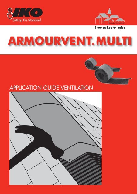
Bitumen Roofshingles<br />
ARMOURVENT MULTI<br />
®<br />
APPLICATION GUIDE VENTILATION
WHY VENTILATE A SHINGLE ROOF?<br />
Unventilated shingle roofs will<br />
cause high temperatures inside.<br />
This will age the shingles much<br />
quicker and at the same time<br />
create unhealthy, moist air <strong>to</strong><br />
live in.<br />
Ventilating the roof will lower<br />
the temperature of both the<br />
shingle roof and the space<br />
directly underneath, leaving the<br />
roof structure unaffected and<br />
preventing accumulation of<br />
moisture in the attic.<br />
Ventilating your roof will<br />
equalize the temperature<br />
of the outer and inner roof.<br />
Your roof structure will then<br />
be able <strong>to</strong> withstand sudden<br />
temperature changes. Especially<br />
those, which are created<br />
by thunders<strong>to</strong>rms during the<br />
summertime. Ventilating the<br />
roof also prevents ice dams.<br />
Ice dams are the results of<br />
continuous freezing and<br />
thawing of snow due <strong>to</strong><br />
escaping heat through the roof<br />
deck being backed up with<br />
frozen slush. If it occurs, water<br />
may be driven under the roof.<br />
Unventilated: high temperature inside. Without air<br />
gap between insulation and roof deck: condensation<br />
forms and the roof structure is damaged.<br />
Ventilated: lower temperature inside. With air gap<br />
between insulation and roof deck: air escapes via<br />
ridge vents, leaving the roof structure unaffected.<br />
A “balanced system” of ventilation, which is the key <strong>to</strong> proper roof ventilation, allows<br />
heat and water vapor <strong>to</strong> escape from the roof system. Air must be able <strong>to</strong> circulate freely<br />
between insulation and the nailable roof deck, from the eaves <strong>to</strong> ridges. This will extend<br />
the life of your roof, increase your living comfort and regulate the moisture in your house,<br />
which will generate lower utility bills because your dryer insulation will function better.<br />
3
A BALANCED SYSTEM: The Key <strong>to</strong> Proper Roof <strong>Ventilation</strong>.<br />
The most important fac<strong>to</strong>r in roof ventilation is the need for a “balanced system”.<br />
This means for every cm² of air exhausted, it must be balanced by providing the<br />
same amount of air intake at the eaves.<br />
Providing a balanced system assures that damaging heat and moisture is being<br />
vented out of the attic, protecting the roof from premature deterioration, costly<br />
repairs. If an attic has a properly balanced system, the airfl ow will move from the<br />
bot<strong>to</strong>m of the attic <strong>to</strong> the <strong>to</strong>p, pushing out heat and moisture in a natural fl ow using<br />
air pressure, thermal effect and diffusion. If the system were <strong>to</strong> be unbalanced, and<br />
the Net Free Area (NFA) at the ridge is higher than at the eave, a reverse airfl ow can<br />
occur causing an opposite effect <strong>to</strong> what is desired. The airfl ow will come from the<br />
<strong>to</strong>p of the house and push down <strong>to</strong>ward the eaves. As a result, heat and moisture are<br />
not allowed <strong>to</strong> escape and additional air and moisture can be drawn in<strong>to</strong> the home.<br />
Recognized by builders throughout the industry, are the standards for static<br />
ventilation, as found in the requirements for proper ventilation. These requirements<br />
call for a ratio of 1:300. This means one cm² of ventilation for every 300 cm² of<br />
insulated roof area. In addition, specifi cations for good attic ventilation require a<br />
balanced system – 50% of the vents at the eave and 50% at the upper portion of the<br />
roof.<br />
4<br />
Intake Air<br />
At Soffit<br />
<strong>Armourvent</strong>® <strong>Multi</strong><br />
Exhaust Exhaust<br />
Airflow<br />
Warm Air Rises<br />
(Thermal effect)<br />
Airflow<br />
Warm Air Rises<br />
(Thermal effect)<br />
Intake Air<br />
At Soffit
CALCULATING THE NET FREE AREA OF VENT OPENINGS<br />
The air gap between the<br />
insulation and the roof deck<br />
must be 4 <strong>to</strong> 6 cm. Air should<br />
fl ow in from the bot<strong>to</strong>m of the<br />
roof (eaves) and out through<br />
the <strong>to</strong>p of the roof (ridge).<br />
The air fl ow between the<br />
eaves and ridge vents must be<br />
unobstructed (by insulation or<br />
roof beams) <strong>to</strong> ensure cross-fl ow<br />
ventilation. The <strong>to</strong>tal required<br />
net free area (NFA) of vent<br />
openings is a function of the<br />
insulated roof area (P) and the<br />
slope of the roof.<br />
SAMPLE ROOF STRUCTURES<br />
Roof slope Required NFA of vent openings<br />
15° - 40° P÷300<br />
41° - 85° P÷600<br />
<strong>Ventilation</strong> should be equally divided among the number of vents at eaves and<br />
ridges.<br />
Example: P = 120 m²; Roof slope = 35°; NFA <strong>Armourvent</strong>® <strong>Multi</strong> = 275 cm²/m<br />
Total required NFA of vent openings:<br />
120÷300 = 0,4000 m² = 4000 cm²<br />
Minimum linear m of vents required over <strong>to</strong>tal roof:<br />
4000/275 = 14,54 m<br />
Linear m of vents at ridge:<br />
14,54÷2 = 7,27 => 7,50 m.<br />
Linear m of vents at eaves:<br />
14,54÷2 = 7,27 => 7,50 m<br />
P<br />
NOTE: Roofs with vapour barriers need 40% less<br />
ventilation. In certain regions (mountainous areas,<br />
the coast) special building regulations may apply.<br />
P<br />
P<br />
5
ARMOURVENT® MULTI ARMOURVENT® MULTI PLUS<br />
Dimensions 6 m x 22,80 cm 6 m x 28,50 cm<br />
Used for Monarch Monarch-Diamant<br />
Armourglass (Vic<strong>to</strong>rian) Diamant<br />
DiamantShield<br />
BiberShield<br />
ArmourShield<br />
Superglass (-Biber)<br />
Marathon Ultra Accessory (Cambridge)<br />
Roof Pitches 15° - 60° 15° - 60°<br />
<strong>Ventilation</strong> area 275 cm²/m 275 cm²/m<br />
DETAILED FIGURES OF <strong>IKO</strong> ARMOURVENT ® MULTI<br />
6<br />
1<br />
Shingle<br />
Detail: <strong>Armourvent</strong>® <strong>Multi</strong> on ridge application. (rafter)<br />
Nail<br />
<strong>Armourvent</strong>® <strong>Multi</strong> Shingle<br />
Ridge Cap<br />
Rafter/Truss<br />
airflow<br />
airflow<br />
Underlay<br />
Solid Sheathing
2<br />
Detail: <strong>Armourvent</strong>® <strong>Multi</strong> on ridge application. (single beam)<br />
Nail<br />
Must penetrate roof deck<br />
airflow<br />
Shingle <strong>Armourvent</strong>® <strong>Multi</strong><br />
airflow<br />
airflow<br />
airflow airflow<br />
Opening Opening<br />
Center<br />
Beam<br />
airflow<br />
3 Detail: <strong>Armourvent</strong>® <strong>Multi</strong> on ridge application. (double beam)<br />
Nail<br />
Must penetrate roof deck<br />
airflow<br />
airflow<br />
airflow<br />
airflow<br />
airflow airflow<br />
Underlay<br />
Shingle <strong>Armourvent</strong>® <strong>Multi</strong><br />
Double<br />
Opening<br />
Beams Opening<br />
Underlay<br />
Decking<br />
airflow<br />
Truss<br />
Decking<br />
airflow<br />
Truss<br />
7
8<br />
4<br />
5<br />
Detail: <strong>Armourvent</strong>® <strong>Multi</strong> off peak application (intake or outlet)<br />
cut here<br />
Roof Sheathing<br />
Vent Detail<br />
Underlay<br />
moisture barrier membrane<br />
cut here<br />
Flashing Detail<br />
Vent Detail<br />
Nail<br />
Must penetrate roof deck<br />
Sealant<br />
Underlay<br />
Shingles<br />
airflow<br />
Detail: <strong>Armourvent</strong>® <strong>Multi</strong> shed roof application<br />
moisture barrier membrane<br />
Nail<br />
Sealant<br />
<strong>Armourvent</strong>® <strong>Multi</strong><br />
airflow<br />
airflow<br />
Underlay<br />
Siding<br />
Sheathing<br />
Off Peak Vent can be<br />
used at upper end of<br />
roof for exhaust or lower<br />
end of roof for intake.<br />
Underlay<br />
Shingles<br />
moisture barrier<br />
Flashing<br />
membrane<br />
<strong>Armourvent</strong>® <strong>Multi</strong><br />
airflow<br />
Underlay<br />
Shingle<br />
Truss/Rafter<br />
Roof Sheathing
6<br />
7<br />
Detail: <strong>Armourvent</strong>® <strong>Multi</strong> eave application. (wide overhang)<br />
Rafter/Truss<br />
Insulation<br />
Soid Sheathing<br />
Underlay<br />
Shingle<br />
airflow<br />
Soid Soffit<br />
Panel<br />
Detail: <strong>Armourvent</strong>® <strong>Multi</strong> eave application. (narrow overhang)<br />
Drip Edge<br />
Fascia<br />
Board<br />
Siding<br />
Rafter/Truss<br />
<strong>Armourvent</strong>® <strong>Multi</strong><br />
Drip Edge<br />
<strong>Armourvent</strong>® <strong>Multi</strong><br />
Insulation<br />
Underlay<br />
Shingle Solid Sheathing<br />
airflow<br />
9
RIDGE VENT INSTALLATION INSTRUCTIONS<br />
The length of slot cut along the roof ridge controls the amount of ventilation. Remember,<br />
for a very attractive roofl ine, it is recommended that <strong>IKO</strong> <strong>Armourvent</strong>s® <strong>Multi</strong> are<br />
<strong>install</strong>ed along the entire ridge of the roof.<br />
I. RIDGE SLOT PREPARATION<br />
Cut a 5cm slot (2,5 cm on each<br />
side of ridge) along the ridge(s).<br />
For a roof with a centre beam,<br />
a 9 cm slot should be cut (4,5<br />
cm on each side of the ridge). A<br />
minimum of 15 cm must be left<br />
uncut on each end of the ridge.<br />
Once the slot is cut and any<br />
overlapping shingles covering the<br />
ridge are trimmed and removed,<br />
the ridge is ready for vent<br />
<strong>install</strong>ation.<br />
II. VENT PLACEMENT ON RIDGE<br />
Roll out and place the <strong>IKO</strong><br />
<strong>Armourvent</strong>® <strong>Multi</strong> along the entire<br />
length of slot also covering the 15 cm<br />
minimum uncut ridge on both ends.<br />
Secure at the lead edge, inserting the<br />
end cap. Pull the vent tight and secure<br />
at about 3 m. Pull the rest of the vent<br />
tight and secure, inserting the end<br />
cap. <strong>Multi</strong>ple lengths of vent can be joined by butting the sections tightly <strong>to</strong>gether. We require<br />
applying <strong>IKO</strong> Shingle Stick ® 3<br />
<strong>to</strong> the shingles, before <strong>install</strong>ing the vent on the ridge. This sealant<br />
should fi ll any voids between the bot<strong>to</strong>m of the vent and the surface of the shingle.<br />
III. END CAP INSTALLATION<br />
Install end caps. Pull apart a pre-cut section of the foam end cap found with the <strong>IKO</strong><br />
<strong>Armourvent</strong>® <strong>Multi</strong>. Use a utility knife, <strong>to</strong> make a cut in the moisture barrier membrane<br />
1,5 cm on each side, back from the end of the section.<br />
10<br />
1<br />
2
Use <strong>IKO</strong> Shingle Stick ®, coat both sides of the moisture barrier membrane between<br />
the foam end cap and the vent underside for a tight seal. Attach vent in the corners<br />
<strong>to</strong> the roof and nail vent and end caps in place <strong>to</strong> roof deck. Drive two nails through<br />
the vent and foam end cap <strong>to</strong> hold foam in place on the ends of the ridge only. Nails<br />
should penetrate the wood roof deck at least 1,5 cm.<br />
IV. RIDGE SHINGLE INSTALLATION<br />
Nail ridge shingles with roofi ng<br />
nails in a common overlapping<br />
pattern. Nails should penetrate<br />
the wood roof deck at least 1,5<br />
cm. The vent has been <strong>install</strong>ed<br />
properly if the bot<strong>to</strong>m of the vent<br />
is fl at on the roof and the peak is<br />
slightly rounded.<br />
HIP VENT INSTALLATION INSTRUCTIONS<br />
I. HIP SLOT PREPARATION<br />
4<br />
To maintain structural<br />
integrity, one continuous slot 1<br />
is not recommended on hip<br />
applications. Start ventilation<br />
preparation by leaving 15 cm<br />
of hip uncut from where the<br />
ridge and hip meet. Cut a 9<br />
cm width slot for ventilation<br />
(4,5 cm on each side of the<br />
hip). Hip slot should be 45 cm<br />
inlength, spaced with a 30 cm uncut area between each 45 cm opening. The slot for<br />
ventilation should not be cut any lower than 1/3 of the roof <strong>to</strong> maintain a balanced<br />
ventilation system.<br />
15<br />
cm<br />
45 cm<br />
30 cm<br />
45 cm<br />
11
II. VENT PLACEMENT ON HIP<br />
Install a minimum of 2 cap shingles<br />
at the bot<strong>to</strong>m of the hip. If the vent<br />
is not being run the entire length of<br />
the hip, the vent should overlap a<br />
minimum of 2 cap shingles at the<br />
end of the vent. Before <strong>install</strong>ing<br />
the vent on the hip, lay a bead of<br />
<strong>IKO</strong> Shingle Stick ® on each side of<br />
the pre-cut slots <strong>to</strong> create a seal.<br />
The bead of sealant should be<br />
applied approximately 2,5 cm from<br />
the edge of the pre-cut slot.<br />
III. HIP AND RIDGE VENT TRANSITION<br />
Using a utility knife <strong>to</strong> trim the end<br />
of <strong>IKO</strong> <strong>Armourvent</strong>® <strong>Multi</strong>. Insert<br />
the foam end cap under the <strong>IKO</strong><br />
<strong>Armourvent</strong>® <strong>Multi</strong> where it is at<br />
full width. Fasten vent for hip at<br />
point where it meets ridge. Roll<br />
out or place the vent all of the<br />
way down the hip, covering 2<br />
pre-laid cap shingles at the bot<strong>to</strong>m of the hip. Go back over hip vents and fasten at<br />
10 cm intervals. If the <strong>Armourvent</strong>® <strong>Multi</strong> is not being run the entire length of the hip,<br />
use the cap shingles <strong>to</strong> create a transition. Use sealant <strong>to</strong> fi ll any void left between<br />
the shingles and the remaining <strong>to</strong>p layer of the vent. Be sure <strong>to</strong> apply roofi ng sealant<br />
<strong>to</strong> any spaces left by cap shingle used for transition. If 2 or more sections of <strong>IKO</strong><br />
<strong>Armourvent</strong>® <strong>Multi</strong> are being joined <strong>to</strong>gether, an end cap MUST be <strong>install</strong>ed in<strong>to</strong> each<br />
end of the joining sections. Repeat on all hips.<br />
IV. HIP AND RIDGE SHINGLE INSTALLATION<br />
Apply the shingles <strong>to</strong> the hip and then <strong>to</strong> the ridge. Nail hip shingles with roofi ng<br />
nails in a common overlapping pattern. Nails should penetrate the wood roof deck at<br />
least 1,5 cm. It is important when <strong>install</strong>ing this vent that you maintain the pitch of the<br />
roof. The vent has been <strong>install</strong>ed properly if the bot<strong>to</strong>m of the vent is fl at on the roof<br />
and the peak is slightly rounded.<br />
12<br />
2<br />
3<br />
4
OFF PEAK VENT INSTALLATION INSTRUCTIONS<br />
1 2<br />
3<br />
I. VENT PREPARATION<br />
Using <strong>IKO</strong> <strong>Armourvent</strong>® <strong>Multi</strong> Plus, peel 7,5 cm of<br />
the moisture barrier membrane away from one<br />
entire side of the vent. Using a utility knife, cut off<br />
7,5 cm of the corrugated air return at one entire<br />
side of the vent.<br />
II. RIDGE EXHAUST/LOWER INTAKE<br />
Cut a horizontal 2 cm slot in the deck where<br />
the desired ventilation is needed. A minimum<br />
of 15 cm must be left uncut on each end of<br />
the slot. Install an underlay on<strong>to</strong> the deck and<br />
trim underlay from slot opening. Caulk edge of<br />
underlay.<br />
III. SHINGLE INSTALLATION<br />
Install shingles, <strong>IKO</strong> Shingle Stick ® the <strong>to</strong>p edge<br />
of shingles and trim shingles from slot opening.<br />
13
IV. VENT INSTALLATION<br />
Install <strong>IKO</strong> <strong>Armourvent</strong>® <strong>Multi</strong> Plus<br />
along the slot opening with the<br />
remaining 7,5 cm corrugated<br />
air return placed approximately<br />
2,5 cm below the ventilation<br />
slot. Nail down the roll, starting<br />
with the lead edge, middle and<br />
other end through the 7,5 cm<br />
air return. Be sure the moisture<br />
barrier membrane is pulled tight<br />
and lay a bead of <strong>IKO</strong> Shingle<br />
Stick ®, 11,5 cm above the<br />
slot, below the moisture barrier<br />
membrane. Nail through the<br />
plastic cap and moisture barrier<br />
membrane in<strong>to</strong> the deck. Install<br />
foam end caps.<br />
V. <strong>IKO</strong> SHINGLE STICK ®<br />
Lay a bead of <strong>IKO</strong> Shingle Stick ®<br />
on front edge of <strong>IKO</strong> <strong>Armourvent</strong>®<br />
<strong>Multi</strong> Plus. <strong>IKO</strong> Shingle Stick ®<br />
on <strong>to</strong>p and behind the vent.<br />
Install an underlay on <strong>to</strong>p of vent<br />
(a minimum of 40 cm). Install<br />
underlay from the vent <strong>to</strong> the<br />
ridge. Lay a bead of <strong>IKO</strong> Shingle<br />
Stick ® on front edge of underlay.<br />
VI. TABS REMOVAL<br />
Using a utility knife, remove<br />
tabs from shingles. Nail this<br />
starterstrip. Nails should penetrate the wood roof deck at least a 1,5 cm. Lay a bead<br />
of <strong>IKO</strong> Shingle Stick ® on the front edge of the starterstrip.<br />
VII. SHINGLE INSTALLATION<br />
Install a minimum of one course of shingles, lapped on <strong>to</strong>p of starterstrip, over vent.<br />
14<br />
4<br />
5<br />
6<br />
7
Install shingles.<br />
ARMOURVENT® MULTI IS MULTI-FUNCTIONAL:<br />
n 2 sizes available for all types of <strong>IKO</strong> shingles<br />
n Can be used for a wide variety of sloped roofs<br />
n Can be used for ridge, hip, soffi t and off peak ventilation<br />
ARMOURVENT® MULTI CAN BE APPLIED VERY QUICKLY:<br />
n Rolls can be cut <strong>to</strong> any desired length<br />
n Easy <strong>to</strong> handle<br />
n No special <strong>to</strong>ols are required<br />
n Easy fastening method<br />
n One pass application<br />
ARMOURVENT® MULTI IS COST EFFICIENT:<br />
n Less openings have <strong>to</strong> be made<br />
n Very fast application<br />
ARMOURVENT® MULTI IS A HIGHLY SOLID MATERIAL:<br />
n Does not crush when nailed<br />
15
<strong>IKO</strong> <strong>Sales</strong> <strong>International</strong> nv<br />
Member of the <strong>IKO</strong> Group - I.Z. Ravenshout 3.815 - 3945 Ham - Belgium<br />
www.iko-shingles.eu