Direct heat meter Conteca Solar - Caleffi
Direct heat meter Conteca Solar - Caleffi
Direct heat meter Conteca Solar - Caleffi

You also want an ePaper? Increase the reach of your titles
YUMPU automatically turns print PDFs into web optimized ePapers that Google loves.
<strong>Direct</strong> <strong>heat</strong> <strong>meter</strong><br />
<strong>Conteca</strong> <strong>Solar</strong> - M-bus Transmission<br />
75525 series<br />
Product range<br />
Technical specifications<br />
Performance:<br />
Electric supply: 24 V (ac) - 50 Hz - 1 W<br />
Long life storage battery: 5 years<br />
Data transmission: using M Bus protocol EN 1434<br />
Antitamper protection<br />
Conformity to standards: EN 1434<br />
Max. percentage of glycol: 50%<br />
REGI STERED BSI EN ISO 9001:2000<br />
Function<br />
Cert. n° FM 21654<br />
UNI EN ISO 9001:2000<br />
Cert. n° 0003<br />
01146/08 GB<br />
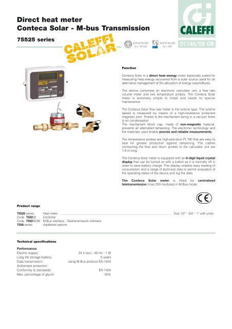
<strong>Conteca</strong> <strong>Solar</strong> is a direct <strong>heat</strong> energy <strong>meter</strong> especially suited for<br />
measuring <strong>heat</strong> energy recovered from a solar source used for an<br />
alternative management of the allocation of energy expenditures.<br />
The device comprises an electronic calculator unit, a flow rate<br />
volume <strong>meter</strong> and two temperature probes. The <strong>Conteca</strong> <strong>Solar</strong><br />
<strong>meter</strong> is extremely simple to install and needs no special<br />
maintenance.<br />
The <strong>Conteca</strong> <strong>Solar</strong> flow rate <strong>meter</strong> is the turbine type. The turbine<br />
speed is measured by means of a high-resistance protected<br />
magnetic joint. Thanks to the mechanism being in a vacuum there<br />
is no condensation.<br />
The mechanism block cap, made of non-magnetic material,<br />
prevents all attempted tampering. The electronic technology and<br />
the materials used enable precise and reliable measurements.<br />
The temperature probes are high-precision Pt 100 that are easy to<br />
seal for greater protection against tampering. The cables<br />
connecting the flow and return probes to the calculator unit are<br />
1,9 m long.<br />
The <strong>Conteca</strong> <strong>Solar</strong> <strong>meter</strong> is equipped with an 8-digit liquid crystal<br />
display that can be turned on with a button as it is normally off in<br />
order to save battery charge. This display enables easy reading of<br />
consumption and a range of technical data to permit evaluation of<br />
the operating status of the device and log the data.<br />
The <strong>Conteca</strong> <strong>Solar</strong> <strong>meter</strong> is fitted for centralised<br />
teletransmission (max 250 modules) in M-Bus mode.<br />
75525 series Heat <strong>meter</strong> Size 1/2” - 3/4” - 1” with union<br />
Code 755000 Controller<br />
Code 755055/56 M-Bus interface - Teletransmission interface<br />
7558 series Additional options
Technical data<br />
Temperature probes<br />
Flow probe length<br />
Return probe length<br />
Probe type<br />
Temperature range limits<br />
Temperature difference limits<br />
Measurement sensitivity<br />
Volumetric part<br />
Dimensions/Connection<br />
Body<br />
Type of hydraulic connection<br />
Nominal flow rate<br />
Lower measurement range<br />
Upper measurement range<br />
Nominal pressure<br />
Max. medium temperature<br />
Installation<br />
Pulse output<br />
Microprocessor calculator unit<br />
Metrological specifications<br />
Centralised transmission<br />
Ambient temperature range limits<br />
Ambient classification<br />
Heat consumption indicator<br />
Electric supply: - (without centralisation)<br />
- (with centralisation)<br />
Protection class<br />
Pulse inputs<br />
Dimensions<br />
120<br />
A<br />
Code<br />
755254<br />
755255<br />
755256<br />
H<br />
165<br />
147<br />
F<br />
G<br />
A<br />
1/2"<br />
3/4"<br />
1"<br />
B<br />
110<br />
130<br />
260<br />
40<br />
B1<br />
190<br />
230<br />
378<br />
A<br />
C<br />
18<br />
21<br />
45<br />
D<br />
96<br />
96<br />
185<br />
E<br />
M07 1259<br />
07185865<br />
B<br />
B1<br />
E<br />
80<br />
80<br />
102<br />
F<br />
44<br />
51<br />
60<br />
G<br />
59<br />
69<br />
82<br />
C<br />
ΔT<br />
Qp<br />
Qi<br />
Qmax<br />
PN<br />
D<br />
H<br />
59<br />
69<br />
87<br />
The <strong>Conteca</strong> <strong>Solar</strong> <strong>heat</strong> <strong>meter</strong> is supplied complete with accessories for<br />
installation, positioning of the probes and subsequent sealing.<br />
Each <strong>Conteca</strong> <strong>Solar</strong> <strong>meter</strong> has n. 2 Y pockets (the flow pocket is fitted<br />
with a mesh strainer).<br />
m<br />
m<br />
°C<br />
K<br />
°C<br />
l/h<br />
l/h<br />
l/h<br />
bar<br />
°C<br />
°C<br />
kWh<br />
1,9<br />
1,9<br />
Pt 100<br />
5–120<br />
0–115<br />
≥0,05<br />
1/2”–1”<br />
brass<br />
male with union ISO 228<br />
see table 1<br />
see table 1<br />
see table 1<br />
threaded PN 10<br />
120<br />
normally horizontal<br />
class OA-OC according to EN 1434-2<br />
in conformity with EN 1434-1<br />
in M-Bus mode<br />
5–45<br />
MID 2004/22/CE E1 - M1<br />
8 digit display<br />
Incorporated battery, 5 year life<br />
24V (ac) - 1W - 50 Hz<br />
according to DIN 40050: IP 54<br />
class IB according to EN 1434-2<br />
TAB. 1 - Flow rate range (m 3 /h) - Connections from 1/2” to 1”:<br />
Code<br />
755254<br />
755255<br />
755256<br />
Meas. type<br />
Single jet<br />
Single jet<br />
Multi jet<br />
Qi<br />
0,12<br />
0,20<br />
0,35<br />
Qp<br />
1,5<br />
2,5<br />
3,5<br />
Qmax<br />
1,5<br />
2,5<br />
3,5
Guidelines for first installation<br />
It is a good rule to have straight sections of piping immediately upstream and downstream from the <strong>meter</strong>.<br />
Length upstream ≥ 4 dia<strong>meter</strong>s.<br />
Length downstream ≥ 2 dia<strong>meter</strong>s.<br />
It is a good rule to have shut-off valves upstream and downstream from the <strong>meter</strong> in order to facilitate installation and maintenance, if required.<br />
In order to protect the <strong>meter</strong>, a strainer is fitted inside the temperature flow pocket.<br />
After installation, it is a good rule to wash the pipes and carry out a pressure test.<br />
After flushing and before securing the temperature probe, it is a good rule to check the state of clogging of the mesh strainer.<br />
After installing the hydraulic part you can install the electric/electronic parts.<br />
The default percentage of glycol set is 30%. If the percentage to be used is not 30%, the actual percentage must be notified when ordering.<br />
Application diagram<br />
Normally the hydraulic installation of the flow-rate <strong>meter</strong> is to be done on the return pipe.<br />
- The hydraulic diagrams given below show:<br />
a) the positioning of the <strong>meter</strong> so that it is at rest when there is no service.<br />
The flow-rate <strong>meter</strong> must preferably be installed in a horizontal position with the turbine axis vertical and respecting the direction of flow<br />
indicated by the arrow on the body.<br />
b) the positioning of the probes<br />
The temperature probes (by means of the pocket) must be positioned on the corresponding flow/return pipes. The corresponding flow and<br />
return pipes are the ones involved with the same flow rate when the flow has started.<br />
M07 1259<br />
07185865<br />
SYSTEM<br />
FLOW<br />
SYSTEM<br />
RETURN<br />
M07 1259<br />
07185865
Hydraulic characteristics<br />
Volume <strong>meter</strong> + pockets for probe<br />
Δp (m w.g.)<br />
5<br />
4,5<br />
4<br />
3,5<br />
3<br />
2<br />
1<br />
0,5<br />
0,25<br />
0,1<br />
2,5<br />
1,8<br />
1,6<br />
1,4<br />
1,2<br />
0,9<br />
0,8<br />
0,7<br />
0,6<br />
0,45<br />
0,40<br />
0,35<br />
0,30<br />
0,25<br />
0,18<br />
0,16<br />
0,14<br />
0,12<br />
0,5<br />
<strong>Conteca</strong> <strong>Solar</strong> <strong>meter</strong> electrical connections<br />
M07 1259<br />
07185865<br />
0,6<br />
0,7<br />
0,8<br />
0,9<br />
1<br />
1,2<br />
1/2"<br />
1,4<br />
Cooling/Heating<br />
mass <strong>meter</strong><br />
1,6<br />
1,8<br />
2<br />
FT Flow temperature probe<br />
3/4"<br />
RT Return temperature probe<br />
2,5<br />
1"<br />
1/2” 3/4” 1”<br />
Kv 2,5 4,2 5,9<br />
For mounting in a box or directly on a wall,<br />
use the screws provided in the package,<br />
fixing them in the curved slots that enable<br />
levelling the device correctly ( A )<br />
3<br />
3,5<br />
4<br />
4,5<br />
Q (m 3 /h)<br />
1 2 3 4 5 6 7 8 9 10 11 12 21 22 23 24 25 26<br />
24 V (a c)<br />
5<br />
N F Tx<br />
Δp (kPa)<br />
45<br />
40<br />
35<br />
30<br />
50<br />
Qp 25<br />
18<br />
16<br />
14<br />
12<br />
9<br />
8<br />
7<br />
6<br />
20<br />
10<br />
4,5<br />
4<br />
3,5<br />
3<br />
2,5<br />
1,8<br />
1,6<br />
1,4<br />
1,2<br />
5<br />
2<br />
1<br />
Rx<br />
Volume <strong>meter</strong><br />
M07 1259<br />
07185865<br />
�<br />
�<br />
FT<br />
Flow Temp. probe<br />
Return Temp. probe<br />
Flow Return<br />
RT
• Data centralisation<br />
In the case of centralised data transmission via bus, the<br />
following connection plan must necessarily be carried<br />
out:<br />
1 - 2 Centralised power supply 24 V (ac)<br />
3 - 5 Transmission bus<br />
3 Tx (Transmission)<br />
5 Rx (Reception)<br />
For the transmission bus, use shieldless cable<br />
2x1mm2type FROR 450/750 2x1 CEI 20-22 IIIMQ (our code 755855/N).<br />
• Energy pulse outputs, code. 755881<br />
21 - 23 Remote thermie totalizer output (kWh)<br />
(Type OC)<br />
These outputs can be connected to our code 755890<br />
(remote energy totalizer) or a general supervisor.<br />
Output specifications:<br />
1 IMP = 1 kWh - open collector contact<br />
Pulse duration: 120 msec<br />
Notes: - The <strong>heat</strong> <strong>meter</strong> is equipped with a storage<br />
battery (life 5 years).<br />
- With centralised transmission it is<br />
necessary and essential to have a power<br />
supply of 24 V (ac) - 50 Hz - 1 W. To prevent<br />
tampering on the device, this line must be<br />
centralised and not under the direct control<br />
of the user.<br />
- Each 75525 series device is supplied with a<br />
kit of lead seals and wire to allow sealing of<br />
both the temperature probes and the plastic<br />
box containing the electronic components.<br />
- Help the cables to pass through by breaking<br />
and shaping the plastic partition in the cable<br />
fairlead.<br />
The basic function of the partition is to protect<br />
the electronic card from dust and from any<br />
spray of water.<br />
755881 Pulse output<br />
The pulse output allows energy data to be transferred to<br />
a generic data acquisition device.<br />
The pulse weighs 1 kWh.<br />
The pulse output with no potential is open collector<br />
with pulse time 120 ms - Vmax 24 V (ac).<br />
Code<br />
755881 Single pulse output - THERMIE<br />
Terminal 21 - 23 Thermie<br />
755881<br />
75525<br />
Acquisition card<br />
(supervisor)<br />
User information cycle<br />
The <strong>heat</strong> <strong>meter</strong> is equipped with a liquid crystal display.<br />
The display is activated by pressing the button on the front PUSH<br />
.<br />
By repeatedly pressing the button briefly it is possible to scroll<br />
through the various information windows.<br />
In order to have a longer battery life, the display is switched off<br />
30 s after last pressing the sensor button.<br />
Heating - Energy (Thermie)<br />
Cooling - Energy (Refrigeration units)<br />
(Not active)<br />
Medium volume<br />
1st supplementary consumption<br />
Flow rate<br />
Power<br />
Flow temperature<br />
Return temperature<br />
Temperature difference<br />
Bus network address<br />
Number of openings in the ABS shell<br />
(Antitamper system)<br />
Check Sum<br />
Segment test<br />
ELECTRONIC OPTIONS<br />
755890 Remote energy totalizer<br />
Electronic 8 digit LCD totalizer equipped with cover plate for<br />
three-slot wall-mounting electric box.<br />
Lithium battery: life 8 years - max frequency 20 Hz<br />
Suitable for pulse outputs code 755881.<br />
Cable length (2x1 mm2 ) not supplied by us: max 150 m.<br />
CALEFFI<br />
ENERGIA kWh<br />
3<br />
4 0 V<br />
23<br />
21<br />
Thermie<br />
➥ ➡ ➡ ➡ ➡ ➡ ➡ ➡ ➡ ➡ ➡ ➡ ➥
We reserve the right to make changes and improvements to the products and related data in this publication, at any time and without prior notice.<br />
CALEFFI<br />
SPECIFICATION SUMMARIES<br />
75525 series<br />
CONTECA SOLAR direct dynamic <strong>heat</strong> <strong>meter</strong> for use in solar <strong>heat</strong>ing systems with the following characteristics: volume<br />
<strong>meter</strong> for hot water with magnetic joint (Maximum temperature 120°C) with pulse output; Pt100 temperature probe; data<br />
visualised on 8 digit display; temperature range 5–120°C; protection class IP 54; transmission via TWO-WAY bus according<br />
to M-bus mode; conformity to EN 1434; electric supply by battery 24 V (ac) in M-bus transmission mode.<br />
CALEFFI S.P.A. · I · 28010 FONTANETO D’AGOGNA (NO) · S.R. 229, N.25 · TEL.INT. +39 0322 8491 R.A. · FAX +39 0322 863723<br />
· Http://www.caleffi.com · E-mail: info@caleffi.it ·<br />
© Copyright 2008 <strong>Caleffi</strong>