Download the APAGEO products catalog
Download the APAGEO products catalog
Download the APAGEO products catalog

Create successful ePaper yourself
Turn your PDF publications into a flip-book with our unique Google optimized e-Paper software.
MATERIALS & SERVICES<br />
for soil investigation, drilling and laboratory<br />
2010-2011 CATALOGUE
2<br />
PREFACE<br />
25 YEARS OF EXPERTISE<br />
<strong>APAGEO</strong> has travelled a long road since its founding in 1984, a road full of<br />
challenges and adventures. Our singular mission remains <strong>the</strong> same as on day<br />
one: to serve <strong>the</strong> geotechnics and drilling industries in France and worldwide.<br />
We have since worked diligently to develop <strong>the</strong> next generation of solutions, invested towards<br />
maximising value for investment and developed to provide for our company’s long-term<br />
viability. The men and women striving over <strong>the</strong> years to grow our company and preserve its<br />
values have accomplished <strong>the</strong> amazing feat of making <strong>APAGEO</strong> an industry leader whilst also<br />
forging our solid reputation. We certainly share our dynamic outlook with our partner<br />
suppliers, whom we involve in our decision-making processes; but above all it is you, our<br />
valued clients, to whom we owe our longevity thanks to your enduring confidence in us.<br />
We have started <strong>the</strong> new year with a new <strong>catalog</strong>ue that is more concise and user-friendly.<br />
Use it as a tool to help you make <strong>the</strong> best decisions for your worksites and crews. In it you<br />
will find all <strong>the</strong> <strong>products</strong> and services you have come to appreciate along with our newest<br />
offerings.<br />
I take this opportunity also to extend my thanks to two key individuals: Michel Gambin,<br />
<strong>APAGEO</strong>’s scientific advisor, whose name is familiar to many, for his reliability and loyalty and<br />
<strong>the</strong> quality of his expertise; and Jean-Paul Robert for his tireless efforts to develop distant<br />
markets and share his knowledge and experience.<br />
My thanks to you both and to all.<br />
Jean-Pierre Arsonnet<br />
Chief Executive Officer<br />
<strong>APAGEO</strong>:<br />
EQUIPMENTS AND SERVICES<br />
Founded in 1984, <strong>APAGEO</strong> manufactures and markets a comprehensive range of<br />
geotechnical and drilling equipment to meet your full requirements. Our teams of<br />
experts with <strong>the</strong>ir extensive knowledge are available at any time to support your<br />
projects.<br />
DESIGN:<br />
Design and Methods Department<br />
PRODUCTION:<br />
Equipment and Tools Production Plant<br />
PRESSUREMETERS AND ELECTRONICS:<br />
Development of in situ measuring equipment<br />
SERVICES:<br />
After-Sales Service and training<br />
3
<strong>APAGEO</strong>: OUR VALUES<br />
AND COMMITMENTS<br />
<strong>APAGEO</strong> AND QUALITY<br />
In our effort to achieve continuous quality improvements, we leverage our full expertise<br />
and seek to develop it fur<strong>the</strong>r on a daily basis with:<br />
<strong>APAGEO</strong> AND SUPPLY STOCKS<br />
Being responsive is one of our main<br />
objectives.<br />
To ensure fastest fulfilment of client requirements,<br />
<strong>APAGEO</strong> operates a warehouse<br />
with a storage area of 615 m2 and capacity<br />
to hold more than 5000 reference <strong>products</strong>.<br />
• Our unique heritage – <strong>the</strong> expertise of Louis Ménard, an international<br />
reference in geotechnics<br />
• Our Design and Methods Department, which ensures <strong>the</strong> highest<br />
quality of our <strong>products</strong> and contributes to all phases from prototype<br />
creation through product design<br />
•Our patented <strong>products</strong>, registered trademarks and full compliance<br />
with EC standards.<br />
<strong>APAGEO</strong> AND CUSTOMER SERVICE<br />
Supporting our clients with <strong>the</strong>ir projects is<br />
important and allows us to ensure optimal<br />
operation and use of our <strong>products</strong>.<br />
For this reason, <strong>APAGEO</strong> offers training<br />
on use of its equipment and on-site<br />
assistance at any time of year in France or<br />
abroad.<br />
<strong>APAGEO</strong><br />
ON THE WORLD STAGE<br />
<strong>APAGEO</strong> has been deploying its expertise internationally for a number of years.<br />
We are currently active in more than 80 countries in Africa, Asia, Oceania, Europe and<br />
<strong>the</strong> Americas.<br />
4 5
6<br />
SOMMAIRE<br />
P.9<br />
P.22<br />
DRILLING RIGS AND ACCESSORIES<br />
DRILLING RIGS APAFOR ® p 10<br />
APAFOR ® 100<br />
APAFOR ® 220<br />
APAFOR ® 330 and APAFOR ® 340<br />
APAFOR ® 440 and APAFOR ® 450<br />
APAFOR ® 450 RS<br />
APAFOR ® 550<br />
APAFOR ® 560<br />
APAFOR ® and more<br />
DRILLING DATA LOGGER EXPLOFOR ® 3 p 18<br />
INJECTION PUMPS AND MIXERS p 20<br />
IN SITU MEASUREMENT EQUIPMENT<br />
MÉNARD PRESSUREMETER AND GEOSPAD ® UNIT<br />
p 23<br />
MÉNARD PRESSUREMETER p 27<br />
KIT, ACCESSORIES AND SPARE PARTS<br />
STAF ® SYSTEM p 48<br />
A SELF–BORED TUBE SYSTEM FOR PRESSUREMETER TEST<br />
MINI PRESSUREMETER p 52<br />
OTHER IN SITU METHOD p 53<br />
Lugeotest ® - Lugeon permeability test<br />
Phicometer - in situ shear test<br />
Light Dynamic Penetrometer<br />
Benkelman Beam (p. 60)<br />
GEOBOX ® p 58<br />
CENTRAL UNIT FOR SOIL INVESTIGATION<br />
GEOPAC ® p 59<br />
AUTO CONTROL PRESSUREMETER WITH GEOBOX ®<br />
GEOVISION ® SOFTWARE p 62<br />
P.64<br />
DRILLING TOOLS AND ACCESSORIES<br />
DRILLING EQUIPMENT p 66<br />
AUGERS AND BITS p 66<br />
Hand augers<br />
Continuous flight augers<br />
Auger bits<br />
Hollow Stem Augers<br />
Injection augers "JET AUGER" type<br />
ROTARY-PERCUSSION DRILLING p 75<br />
Rods and bits for top hammer rotary-percussion [R32 – R38]<br />
Down-<strong>the</strong>-hole hammers and bits<br />
Overburden drilling – STAREX equipment<br />
Overburden drilling – S.T.A.R. equipment<br />
ROTATION DRILLING p 81<br />
Drilling rods – penetrometer rods - couplings<br />
Rotation bits (tricones, drag bits, special bits)<br />
CORING EQUIPMENT p 88<br />
Single Core barrels B – T<br />
Double core barrels T2 - T6 – TRIPLEX T6S and K2<br />
Tungsten carbide bits and reaming shells<br />
Wireline core barrel<br />
Diamond bits<br />
Push samplers – SPT – Thin wall samplers<br />
Casing (metric, LS, W series, …).<br />
Accessories for Q casing – foot clamp<br />
P.113 ACCESSORIES<br />
AND LABORATORY EQUIPMENT<br />
P.122<br />
P.123<br />
ACCESSORIES AND DRILLING PRODUCTS p 114<br />
Drilling mud and grease<br />
Straight pipe and chain wrenches<br />
Water level – packers<br />
LABORATORY EQUIPMENT p 118<br />
Granular, soil, cement, concrete and bitumus testings<br />
Drilling mud equipment<br />
Non destructive testing<br />
GENERAL SALES CONDITIONS<br />
A TO Z INDEX<br />
7
<strong>APAGEO</strong>’S DESIGN<br />
AND METHODS DEPARTMENT<br />
Our Design and Methods Department is<br />
responsible for designing and defining<br />
<strong>the</strong> company’s various <strong>products</strong>. Ready<br />
to adapt to client requirements using<br />
its creativity and field knowledge, it<br />
devises technical solutions and<br />
assures <strong>the</strong> highest quality of all<br />
parts whilst identifying <strong>the</strong> most suitable<br />
materials for <strong>the</strong>ir manufacture.<br />
Its primary activities consequently<br />
include planning production, finalising<br />
<strong>the</strong> technical specifications of each<br />
machine, ensuring conformity of <strong>the</strong><br />
end <strong>products</strong> to client requirements,<br />
organising <strong>the</strong> various phases of <strong>the</strong> operations process and ensuring timely delivery to<br />
clients.<br />
Continually seeking innovation, it carries out client-specific projects using <strong>the</strong> most powerful<br />
tools currently available such as SolidWorks for 3D CAD and Cosmos for <strong>the</strong> calculation<br />
component.<br />
The Design and Methods Department plays a key role in developing <strong>APAGEO</strong>’S equipment<br />
by maximising <strong>the</strong> performance of our current line whilst also conceiving new<br />
solutions with a view to offering our clients <strong>products</strong> that meet <strong>the</strong>ir requirements as<br />
effectively as possible.<br />
DRILLING RIGS AND ACCESSORIES<br />
P.10<br />
DRILLING RIGS APAFOR®<br />
APAFOR ® 100<br />
APAFOR ® 220<br />
APAFOR ® 330 and APAFOR ® 340<br />
APAFOR ® 440 and APAFOR ® 450<br />
APAFOR ® 450 RS<br />
APAFOR ® 550<br />
APAFOR ® 560<br />
APAFOR ® and more<br />
P.18 DRILLING DATA LOGGER EXPLOFOR® 3<br />
WITH GEOBOX ®<br />
P.20<br />
INJECTION PUMPS AND MIXERS<br />
8 9
10<br />
APAFOR ® 100<br />
Technical specifications<br />
(for any modification, contact us)<br />
Ref: D10 800000<br />
Performances<br />
Blowing speed:<br />
25 blows/min<br />
Hammer weight:<br />
63,5 kg<br />
Falling height:<br />
75 cm<br />
General Information<br />
• Heavy dynamic penetrometer, NF P 94-115<br />
and EN ISO 22476-2 standards<br />
• Penetration test type B (DPSH) and SPT<br />
• The rig can be operated by one person<br />
only<br />
Standard specifications<br />
• 10 HP HATZ diesel engine<br />
• Electric blow counter integrated on <strong>the</strong><br />
control panel<br />
• Hydraulic extraction system 7 tons with<br />
pedal<br />
• Boxes for rods, tools and cones<br />
Option<br />
• Rotation head for auger drilling with 63mm<br />
auger guide on <strong>the</strong> penetrometer<br />
• Winch with cable and shackle<br />
(capacity=470 kg)<br />
• Mechanically welded steel frame to support<br />
<strong>the</strong> penetrometer system when exchanged<br />
with <strong>the</strong> rotation head<br />
APAFOR ® 220<br />
Technical specifications<br />
(for any modification, contact us)<br />
Ref: U2 7100702 (standard)<br />
Ref: U2 7100703 (trailer)<br />
General information<br />
• Very compact rig for difficult site access<br />
• Very attractive power-weight ratio<br />
• Drilling for pressuremeter tests at lowest cost<br />
• Drilling with auger and Down The Hole hammer<br />
drilling<br />
• Small diameter coring at shallow depth<br />
Standard specifications<br />
• 26 HP Caterpillar diesel engine<br />
• Mast lengst 2.75 m – useful stroke 1.98 m<br />
• 4 mechanical stabilisation feet<br />
• Emergency stops on <strong>the</strong> control panel and<br />
remote control<br />
• Mounted on a variable width rubber track<br />
manually operated from 700 to 1060 mm<br />
• Standard rotary head<br />
• Auger guide<br />
• Remote moving control (wireless possible)<br />
• Proportional hydraulic controls<br />
Weight<br />
• 1100 Kg (without option)<br />
Performances<br />
Rotation speed:<br />
0 to 100 rpm<br />
Max. Torque:<br />
100 daN.m<br />
Rotary head translation<br />
speed:<br />
22 m/min<br />
Pull-up force:<br />
1600 daN<br />
Mast lengths<br />
Options<br />
Useful stroke<br />
Auger guide or rod clamp 4T<br />
1.95 m 1.18 m<br />
2.45 m 1.68 m<br />
2.75 m 1.98 m<br />
• Hydraulic rod clamp 40 kN force<br />
• Thermal engine injection pump<br />
mounted on independent skid<br />
• Fitting of a heavy dynamic<br />
penetrometer (DPSH, SPT<br />
and hammering works)<br />
• Capstan for semi automatic<br />
heavy penetrometer or SPT<br />
• Speed rotation engine for coring<br />
• Percussion hammer<br />
• Trailer for transportation<br />
• Available mounted on a trailer<br />
without rubber track<br />
• Prefitting for drilling data logger<br />
(light or full)<br />
• Hydraulic manipulation winch<br />
• Hydraulic stabilisation feet<br />
Drilling rigs and accessories<br />
11
12<br />
APAFOR ® 330 & 340<br />
Technical specifications<br />
(for any modification, contact us)<br />
Ref: U3 7100101 (330)<br />
Ref: U3 7100103 (340)<br />
Ref: U3 7100100 (340 trailer)<br />
Performances<br />
Rotation speed:<br />
0 to 86 rpm<br />
Max. Torque:<br />
190 daN.m<br />
Rotary head translation speed:<br />
22 m/min<br />
Pull-up force:<br />
1600 daN<br />
Mast lengths<br />
Useful stroke<br />
Auger guide or rod clamp 4T<br />
1.95 m 1.18 m<br />
2.45 m 1.68 m<br />
2.75 m 1.98 m<br />
General information<br />
• Very compact rig for difficult site access<br />
• Very attractive power-weight ratio<br />
• Drilling for pressuremeter tests<br />
• Micro piling (auger or Down The Hole hammer)<br />
• Coring at medium depth<br />
Standard specifications<br />
• 32 HP HATZ soundproofed diesel engine (APAFOR 330)<br />
• 41 HP DEUTZ diesel engine (APAFOR 340 and 340 trailer)<br />
• Mast length 2.75 m – useful stroke 1.98 m<br />
• Mechanically welded steel frame mounted on a hydraulic<br />
variable width rubber track from 700 to 1060 mm<br />
• 4 mechanical stabilisation feet<br />
• Proportional hydraulic controls on control panel<br />
• Emergency stops on <strong>the</strong> control panel and remote control<br />
• Auger guide<br />
• Remote moving control (wireless possible)<br />
• Standard rotary head<br />
Weight<br />
• 1400 Kg (without option)<br />
Options<br />
• Hydraulic rod clamp 40 kN force<br />
• Thermal engine injection pump mounted on independent<br />
skid<br />
• Fitting of a heavy dynamic penetrometer (DPSH, SPT and<br />
hammering works)<br />
• Capstan for semi automatic heavy<br />
penetrometer<br />
• Speed rotation engine for coring<br />
• Trailer for transportation<br />
• Hydraulic manipulation winch<br />
• Percussion hammer<br />
• Prefitting for drilling data<br />
logger (light or full)<br />
• Hydraulic stabilisation feet<br />
APAFOR 340<br />
AVAILABLE ON TRAILER<br />
VERSION<br />
APAFOR ® 440 & 450<br />
Technical specifications<br />
(for any modification, contact us)<br />
Ref: U3 8710101 (440)<br />
Ref: U4 5710101 (450)<br />
p. 20-21<br />
General information<br />
• Powerful and versatile drilling rigs, able to perform<br />
coring, rotary or rotary-percussion drilling operation<br />
thanks to its top hammer, <strong>the</strong> ideal equipment for<br />
soil investigation<br />
• Large speed and torque range thanks to <strong>the</strong>ir<br />
variable volumetric displacement hydraulic motor<br />
and proportional distributors<br />
Standard specifications<br />
• 41 HP DEUTZ diesel engine (APAFOR 440)<br />
• 48 HP HATZ soundproofed diesel engine<br />
(APAFOR 450)<br />
• Floating shaft equipped with a swivel having two<br />
threads : male 2"3/8 IF and female R38<br />
• Rotary percussion head with proportional hydraulic<br />
control, top hammer<br />
• Mast length 3.65 m – useful stroke 2.25 m,<br />
inclination +/-15%<br />
• Light prefitting for drilling data logger<br />
• Prefitting for an hydraulic injection pump<br />
• Rod clamp 80 kN force<br />
• 4 hydraulic jacks<br />
• Mechanically welded steel frame mounted<br />
on a hydraulic rubber track 140cm width<br />
• Remote moving control (wireless possible)<br />
• Rods rack<br />
Weight<br />
• 2 600 kg (without option)<br />
Options<br />
• Hydraulic sliding of drilling head<br />
(except for frame with variable width)<br />
• Hydraulic Piston Injection pump<br />
• Hydraulic injection pump (GAMA 80)<br />
• Rock drilling mast advance system<br />
• Hydraulic manipulation winch<br />
• Wireline winch<br />
• Hydraulic variable rubber track<br />
(from 0.72 m to 1.02 m)<br />
• Capstan for SPT<br />
Performances<br />
(o<strong>the</strong>r performances available<br />
please see page 17)<br />
Rotation speed:<br />
0 to 700 rpm<br />
Variable torque:<br />
0 to 220 daN.m<br />
Pull-up force:<br />
4000 daN<br />
Hydraulic hammer :<br />
180 joules – 1300 bpm<br />
Rotary-percussion<br />
head<br />
Useful stroke<br />
Mast<br />
Rod clamp 8T Rod clamp 8T<br />
lengths<br />
Rotary head<br />
Double rod<br />
clamp 8T<br />
3.45 m 2.03 m 2.03 m -<br />
3.65 m 2.25 m 2.25 m 2.25 m<br />
• Rods unscrewing hydraulic wrench<br />
• Road trailer four wheeled for transportation<br />
• Rotation speed sensor (VIR®)<br />
• Full prefitting for drilling data logger<br />
• Removable receptacle for rods (length 1.8m)<br />
• O<strong>the</strong>r rotary heads, see p.17<br />
Drilling rigs and accessories<br />
13
14<br />
APAFOR ® 450 RS<br />
Technical specifications<br />
(for any modification, contact us)<br />
Ref: U45 700002<br />
General information<br />
• Versatile rig, track mounted for<br />
difficult site access.<br />
• Very attractive power-weight ratio<br />
• Continuous flight auger, rotary<br />
and Down-<strong>the</strong>-hole hammer<br />
drilling, coring<br />
• Fully self-sufficient thanks to its<br />
serial injection pump fitting<br />
Standard specifications<br />
• 48 HP Hatz soundproofed diesel<br />
engine<br />
• Mechanically welded steel frame<br />
mounted on a rubber track 1,4 m<br />
width<br />
• Safety devices : Emergency stop<br />
on <strong>the</strong> control panel<br />
• Floating shaft with pin thread 2’’3/8 IF (o<strong>the</strong>r threads available)<br />
• Pull-up force : 1800 daN.m<br />
• Handling with hydraulic controls<br />
• 4 hydraulic jacks for stabilisation<br />
• Mast length : 3.56 m useful stroke 2.31 m<br />
• Hydraulic rod clamp 8 tonnes<br />
• Swift injection swivel at <strong>the</strong> top of <strong>the</strong> rotation head<br />
• Dimensions : L 3.060 x W 1.400 x H 3.730 m (drilling position)<br />
Weight<br />
• 2 750 kg (without option)<br />
Options<br />
• Hydraulic injection pump<br />
• Hydraulic sliding of drilling head<br />
• Manipulation winch<br />
• Light prefitting for drilling data logger<br />
Performances<br />
double torque<br />
Rotation speed:<br />
0 to 87 rpm<br />
(auger configuration)<br />
0 to 435 rpm<br />
(coring configuration)<br />
Double Torque:<br />
280 daN.m<br />
(auger configuration)<br />
56 daN.m<br />
(coring configuration)<br />
APAFOR ® 550<br />
Technical specifications<br />
(for any modification, contact us)<br />
Ref: U3 8710100<br />
General information<br />
• Powerful and versatile drilling rigs, able to<br />
perform coring, rotary or rotary-percussion<br />
drilling operation thanks to its top hammer,<br />
<strong>the</strong> ideal equipment for soil investigation<br />
• Large speed and torque range thanks to<br />
<strong>the</strong>ir variable volumetric displacement<br />
hydraulic motor and proportional<br />
distributors<br />
Standard specifications<br />
• 53 HP DEUTZ air and oil cooling diesel<br />
engine<br />
• Floating shaft equipped with a swivel having<br />
two threads: male 2"3/8 IF and female R38<br />
• Rotary-percussion head with proportional<br />
hydraulic control, top hammer<br />
• Mast length 3.85 m – useful stroke 2.25 m,<br />
inclination +/-15%<br />
• Light prefitting for drilling data logger<br />
• Prefitting for an injection pump<br />
• Rod clamp 80 kN force<br />
• 4 hydraulic jacks<br />
• Mechanically welded steel frame mounted<br />
on a hydraulic rubber track 140cm width<br />
• Rod rack<br />
• Remote moving control (wireless possible)<br />
Weight<br />
• 2800 Kg (without option)<br />
Options<br />
• Hydraulic sliding of drilling head<br />
• Hydraulic injection pump<br />
• Hydraulic manipulation winch<br />
• Wireline winch<br />
• Capstan for SPT<br />
• Double rod clamp<br />
• Rotation speed sensor (VIR®)<br />
Performances<br />
(o<strong>the</strong>r performances available<br />
please see page 17)<br />
Rotation speed:<br />
0 to 500 rpm<br />
Variable torque:<br />
0 to 280 daN.m<br />
Pull-up force:<br />
4000 daN<br />
Hydraulic hammer:<br />
180 joules – 1300 bpm<br />
Useful stroke<br />
Rotary-percussion head Rotary head<br />
Mast<br />
Double rod<br />
Rod clamp 8T<br />
lengths clamp 8T<br />
Rod clamp 8T<br />
Double rod<br />
clamp 8T<br />
3.65 m 2.25 m - 2.25 m 2.25 m<br />
3.85 m 2.25 m 2.25 m 2.25 m 2.25 m<br />
4.11 m 2.71 m 2.71 m 2.71 m 2.71 m<br />
4.41 m 3.05 m 3.02 m 3.05 m 3.05 m<br />
• Full prefitting for drilling data logger<br />
• Road trailer four wheeled for transportation<br />
• Removable receptacle for rods<br />
• Rock drilling mast advance system<br />
• O<strong>the</strong>r rotary head, contact us<br />
Drilling rigs and accessories<br />
15
16<br />
APAFOR ® 560<br />
Technical specifications<br />
(for any modification, contact us)<br />
Ref: U5 6700000<br />
General information<br />
• Powerful and versatile drilling rigs, able to<br />
perform coring, rotary or rotary-percussion<br />
drilling operation thanks to its top hammer,<br />
<strong>the</strong> ideal equipment for soil investigation<br />
• Large speed and torque range thanks to<br />
<strong>the</strong>ir variable volumetric displacement<br />
hydraulic motor and proportional<br />
distributors<br />
Standard specifications<br />
• 60 HP CATERPILLAR diesel engine<br />
• Floating shaft equipped with a swivel having<br />
two threads: male 2"3/8 IF and female R38<br />
• Rotary-percussion head with proportional<br />
hydraulic control, top hammer<br />
• Mast length 3.85 m – useful stroke 2.25 m,<br />
inclination +/-15%<br />
• Light prefitting for drilling data logger<br />
• Prefitting for an injection pump<br />
• Rod clamp 80 kN force<br />
• 4 hydraulic jacks<br />
• Mechanically welded steel frame mounted<br />
on a hydraulic rubber track 140cm width<br />
• Road trailer coupling<br />
• Remote moving control (wireless possible)<br />
• Rod rack<br />
Weight<br />
• 2 900 kg (without option)<br />
Options<br />
• Hydraulic injection pump (SIGMA 100)<br />
• Hydraulic sliding of drilling head<br />
• Hydraulic manipulation winch<br />
• Wireline winch<br />
• Capstan for SPT<br />
• Double rod clamp<br />
• Rotation speed sensor (VIR ® )<br />
Performances<br />
(o<strong>the</strong>r performances available<br />
please see page 17)<br />
Rotation speed:<br />
0 to 510 rpm<br />
Variable torque:<br />
0 to 310 daN.m<br />
Pull-up force:<br />
4000 daN<br />
Hydraulic hammer:<br />
180 joules – 1300 bpm<br />
Useful stroke<br />
Rotary-percussion head Rotary head<br />
Mast<br />
Double rod<br />
Rod clamp 8T<br />
lengths clamp 8T<br />
Rod clamp 8T<br />
Double rod<br />
clamp 8T<br />
3.65 m 2.25 m - 2.25 m 2.25 m<br />
3.85 m 2.25 m 2.25 m 2.25 m 2.25 m<br />
4.11 m 2.71 m 2.71 m 2.71 m 2.71 m<br />
4.41 m 3.05 m 3.02 m 3.05 m 3.05 m<br />
• Full prefitting for drilling data logger<br />
• Rock drilling mast advance system<br />
• Road trailer<br />
• Removable receptacle for rods<br />
• O<strong>the</strong>r rotary head, contact us<br />
APAFOR ® and its variants<br />
Additional rotary heads for more performances<br />
Available for<br />
APAFOR ® 220 / 330 / 340<br />
Fast coring head:<br />
Rotation speed: 0 to 500 rpm<br />
Variable torque: 0 to 32 daN.m<br />
Hammering head/device:<br />
80 - 100 joules<br />
1650 bpm<br />
Available for<br />
APAFOR ® 440 / 450 / 550 / 560<br />
Micro piling rotation head<br />
(APAFOR ® 450)<br />
Rotation speed: 0 to 210 rpm<br />
Variable torque: 0 to 310 daN.m<br />
Simple rotation head<br />
(APAFOR ® 440 / 450)<br />
Rotation speed: 0 to 93 rpm<br />
Variable torque: 0 to 350 daN.m<br />
Special rotation head for coring<br />
(APAFOR ® 440 / 450)<br />
Rotation speed: 0 to 1080 rpm<br />
Variable torque: 0 to 145 daN.m<br />
Special rotation head for coring<br />
(APAFOR ® 550 / 560)<br />
Rotation speed: 0 to 780 rpm<br />
Variable torque: 0 to 185 daN.m<br />
Special rotation head<br />
with high torque<br />
(APAFOR ® 550 / 560)<br />
Rotation speed: 0 to 56 rpm<br />
Max torque: 560 daN.m<br />
RotoSTAF ®<br />
rotation head<br />
Configured for simultaneous<br />
bidirectional rotation and<br />
with percussion for <strong>the</strong><br />
implementation of <strong>the</strong> Self<br />
Bored tube system for<br />
pressuremeter test<br />
(STAF ® method)<br />
Drilling rigs and accessories<br />
17
EXPLOFOR ® 3<br />
DRILLING DATA RECORDER<br />
General presentation<br />
The new version of EXPLOFOR ® has arrived. EXPLOFOR ® 3<br />
records drilling parameters through <strong>the</strong> central unit, GeoBOX ® :<br />
less equipment to handle, a unique tool to centralize and visualize<br />
data.<br />
EXPLOFOR ® , designed, developed and produced by <strong>APAGEO</strong>,<br />
enables <strong>the</strong> recording of drilling parameters during <strong>the</strong> drilling<br />
process with a view to collecting real time information on <strong>the</strong><br />
soil profile. These data can also be used to choose adapted soil<br />
testing investigations (PRESSUREMETER, SPT, etc.) to <strong>the</strong> soil at<br />
hand.<br />
APAFOR ® - <strong>APAGEO</strong>'s range of drilling rigs - are equipped in series with quick hydraulic couplings and<br />
electrical wires for connecting EXPLOFOR ® system (APAFOR ® 400 series or higher).<br />
BY BY <strong>APAGEO</strong><br />
<strong>APAGEO</strong><br />
® ®<br />
GEOSPAD ®<br />
EXPLOFOR<br />
DYNAMIC<br />
PENETROMETER<br />
® 3<br />
LUGEOTEST ®<br />
GEOSPAD<br />
PHICOMETER<br />
®<br />
EXPLOFOR<br />
DYNAMIC<br />
PENETROMETER<br />
® 3<br />
LUGEOTEST ®<br />
PHICOMETER<br />
IMPLEMENTATION<br />
GeoBOX ® records via WIFI <strong>the</strong> data while drilling, through a tinny black box connected to your drilling rig.<br />
Data can be visualized on screen with an adjustable depth scale and sent to <strong>the</strong> deported printer at <strong>the</strong><br />
end of drilling.<br />
EXPLOFOR ® 3 records <strong>the</strong> following parameters:<br />
• Advance rate (depth and penetration speed)<br />
• Rotating torque of <strong>the</strong> rotary head<br />
• Pushing force (thrust) on drilling bits<br />
• Injection pressure of drilling fluid<br />
• Optional: VIR ® - a rotation speed sensor (APAFOR ® 400 or higher), VIBRASOL ® - reflective energy holding pressure, flow<br />
Data from EXPLOFOR ® 3 can be processed directly using ourgeotechnical data processing software, GeoVision ® .<br />
p. 62-63<br />
p. 58<br />
EXPLOFOR ® 3 is equipped with <strong>the</strong> following:<br />
• GeoBOX ® , Ultra Mobile PC extremely rugged, IP54, high storage capacity, with<br />
printer and adaptor, in hardy waterproof case.<br />
• A new generation of remote unit for EXPLOFOR ® 3 allows direct reading of <strong>the</strong><br />
borehole depth, with more flexibility to <strong>the</strong> main control. (start, stop, restart). It<br />
can be positioned on <strong>the</strong> control panel of <strong>the</strong> drilling rig for easy operation of<br />
EXPLOFOR ® 3 during drilling.<br />
• New depth encoder: penetration rate/depth sensor, compact and light, it is<br />
equipped with an electromagnetic rewinding brake to avoid damages.<br />
• Junction box that will be mounted on <strong>the</strong> drilling rig for centralized connection of EXPLOFOR ®<br />
sensors and communication with GeoBOX ® via WIFI.<br />
• 3 pressure sensors.<br />
• USB storage key.<br />
EXPLOFOR ® 3 is 100% compatible with your existing EXPLOFOR ® sensors and depth encoder.<br />
DESCRIPTION Reference<br />
EXPLOFOR ® 3 complete (with pressure sensors and depth encoder) N7 5900600<br />
Speed and depth sensor (encoder) N4 5910002<br />
Pressure sensor 200 bars (torque and pressure on bit) N1 5900400<br />
Pressure sensor 70 bars (for injection pressure) N1 5900389<br />
Paper roll N4 5900001<br />
Power cable N9 5900433<br />
Junction box (sensors connection) N7 5900601<br />
Remote drilling unit and display N7 5900602<br />
EXPLOFOR ® 3<br />
DRILLING DATA RECORDER<br />
Options<br />
VIR ® : Rotation speed sensor<br />
<strong>APAGEO</strong> has developed a rotation speed sensor suitable<br />
for use on all APAFOR ® 400 and higher geotechnical rigs.<br />
This system is made up of a display unit positioned near<br />
<strong>the</strong> control panel of <strong>the</strong> rig and a sensor inserted directly<br />
into <strong>the</strong> rig's rotating head, offering maintenance-free<br />
operation while eliminating all outside disturbances.<br />
This system can be used independently from <strong>the</strong> recorder<br />
EXPLOFOR ® 3.<br />
VIBRASOL ® : Reflective energy<br />
To complement <strong>the</strong> monitoring of pressure and <strong>the</strong><br />
advance rate, <strong>APAGEO</strong> presents VIBRASOL ® , a new<br />
system for measuring reflective energy based on <strong>the</strong> depth<br />
of <strong>the</strong> drilling bit in <strong>the</strong> soil and <strong>the</strong> vibrations and impacts<br />
to which it is subjected.<br />
Additional options available:<br />
• Onboard GPS for localisation of sounding position<br />
• Extra pressure sensors (10, 20, 70, 100 or 200 bars)<br />
• Installation kit for hydraulic drilling rig (hydraulic couplings, support plate for encoder)<br />
• GeoBOX ® accessories<br />
OPTIONS Reference<br />
V.I.R. ® N4 5960000<br />
Vibrasol ® N4 5970000<br />
Onboard GPS EXPLOFOR ® 3 N4 5900037<br />
Installation kit for drilling rig N1 5900420<br />
18 19<br />
- Spare parts for Explofor ® first and second generation, please consult us<br />
p. 58<br />
Drilling rigs and accessories
20<br />
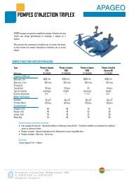
INJECTION PUMPS<br />
AND MIXERS<br />
TRIPLEX INJECTION PUMPS WITH THERMAL ENGINE<br />
Triplex injection pumps with <strong>the</strong>rmal engine<br />
Designation Max Pressure Max Flow Reference<br />
Injection valve pump 5,5 HP engine – V75 30 bars 58 l/min C3 0101604<br />
Injection valve pump 9 HP engine – V105 30 bars 85 l/min C3 0101605<br />
Balls pump 9 HP engine – Gama 80 40 bars 76 l/min C3 0101601<br />
Balls pump 9 HP engine – Sigma 100 40 bars 100 l/min C3 0101607<br />
Triplex injection pumps with hydraulic engines<br />
Designation Max Pressure Max Flow Reference<br />
Injection valve pump – HY - V75 30 bars 68 l/min C0 0101601<br />
Injection valve pump – HY - V105 30 bars 105 l/min C2 0301500<br />
Injection valve pump – HY - V160 30 bars 160 l/min C2 0301600<br />
Balls pump – HY - Gama 80 40 bars 80 l/min C2 0101601<br />
Balls pump – HY - Sigma 100 40 bars 100 l/min C2 0101604<br />
NOTE: pumps are delivered with a 3 meters suction pipe and a strainer.<br />
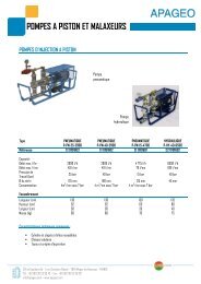
INJECTION PUMPS<br />
AND MIXERS<br />
PISTON PUMPS FOR CLEAR WATER, MUD AND CEMENT GROUT<br />
Pneumatic versions<br />
Designation Max Pressure Max Flow Reference<br />
P-PN-25-2900 25 bars 49 l/min C1 0101603<br />
P-PN-40-2900 40 bars 49 l/min C1 0101602<br />
P-PN-15-4700 15 bars 79 l/min C1 0101601<br />
Hydraulic versions<br />
Designation Max Pressure Max Flow Reference<br />
P-HY-40-6500 40 bars 108 l/min C2 0101602<br />
P-HY 25 25 bars 60l/min C2 0101600<br />
MIXERS FOR DRILLING MUD AND CEMENT GROUT<br />
Designation Speed Power Reference<br />
Hydraulic - Consumption 30 l/min at 50 bars 0 – 1 200 rpm 6 500 W C8 0101301<br />
Pneumatic- Consumption 480 l/min at 7 bars 0 – 3 000 rpm 600 W C7 0101301<br />
ACCESSORIES<br />
Designation Reference<br />
Hand pump – injected volume = 600 ml / return C6 0101601<br />
Hydraulic central unit with 2 circuits (pump and mixer) 11 HP engine C0 0101600<br />
Oil feeder for pneumatic equipment H3 09000703<br />
Drilling rigs and accessories<br />
21
22<br />
IN SITU MEASUREMENT EQUIPMENT<br />
P.23 MÉNARD PRESSUREMETER AND GEOSPAD® UNIT<br />
General presentation<br />
P.27<br />
MÉNARD PRESSUREMETER<br />
Complete kits<br />
Accessories (probes, tubing, slotted tube, extension tube…)<br />
Spare parts (pressure gauge, control valve…)<br />
P.48 STAF® SYSTEM<br />
A SELF–BORED TUBE SYSTEM<br />
FOR PRESSUREMETER TEST<br />
P.52<br />
P.53<br />
P.58 GEOBOX®<br />
P.59 GEOPAC®<br />
MINI PRESSUREMETER<br />
OTHER IN SITU METHOD<br />
Lugeotest ® - Lugeon permeability test<br />
Phicometer - in situ shear tester<br />
Light Dynamic Penetrometer<br />
Benkelman Beam (p.60)<br />
CENTRAL UNIT FOR SOIL INVESTIGATION<br />
AUTO CONTROL PRESSUREMETER WITH GEOBOX ®<br />
P.62 GEOVISION® SOFTWARE<br />
GEOTECHNICAL DATA PROCESSING SOFTWARE<br />
MÉNARD<br />
PRESSUREMETER<br />
PRESSUREMETER TEST ACCORDING<br />
TO THE EN ISO 22476-4<br />
AND ASTM D-4719-00 STANDARDS<br />
EQUIPMENT<br />
Control Unit (CU), tubing and three-cell probe<br />
to perform in situ pressuremeter tests.<br />
TEST DESCRIPTION<br />
A pressuremeter test is an in situ controlled loading test<br />
performed on <strong>the</strong> wall of a borehole using a cylindrical probe that<br />
expands radially.<br />
From <strong>the</strong> test readings (volume variation based on controlled<br />
pressure), a stress-strain curve can be obtained for <strong>the</strong> soil at<br />
hand in <strong>the</strong> case of plane deformation.<br />
Testing enables definition of three parameters:<br />
- Ménard pressuremeter modulus,<br />
- Creep pressure<br />
- Limit pressure<br />
1. Control Unit<br />
The CU is equipped to precisely regulate <strong>the</strong> pressure of <strong>the</strong> probe to apply controlled loads to <strong>the</strong> soil and <strong>the</strong>n to<br />
measure volume increases over pressure. Positioned in an aluminium box standing on a tripod, it includes a 800 cm3<br />
volumeter with sight tube, a main pressure regulator, a differential pressure regulator and pressure gauges for 0-25 and<br />
0-60 bars (0-100 bar gauge) for monitoring <strong>the</strong> pressure applied to <strong>the</strong> measuring and guard cells. A nitrogen cylinder<br />
provides <strong>the</strong> pressure source.<br />
2. Plastic tubing<br />
This coaxial or twin tubing, flexible and highly resistant with small dilatation, connects <strong>the</strong> control unit to <strong>the</strong> probe.<br />
3. Three-cell probe<br />
This component includes a central measuring cell, filled with water. Its volume changes are read on <strong>the</strong> Control Unit<br />
volumeter. The probe is totally protected by a rubber cover (different types depending on nature of soil) which is<br />
inflated by <strong>the</strong> gas to form <strong>the</strong> two guard cells, one on ei<strong>the</strong>r side of <strong>the</strong> central cell. The pressure applied to <strong>the</strong> three<br />
cells is balanced to ensure true cylindrical deformation along <strong>the</strong> measuring cell.<br />
TEST PROCEDURE<br />
The borehole is drilled so as to minimize wall disturbance and maintain a cavity diameter compatible with <strong>the</strong> probe size (63<br />
or 76 mm). The probe is lowered into <strong>the</strong> borehole to <strong>the</strong> required test depth and <strong>the</strong> pressure is applied by equal increments<br />
using <strong>the</strong> Control Unit.<br />
In gravelly or sloughy soils with risk of collapse of <strong>the</strong> borehole wall, <strong>the</strong> probe may be inserted into a specially designed<br />
slotted tube which can be directly hammered or vibrodriven into <strong>the</strong> soil or inserted at <strong>the</strong> time of drilling. Used without<br />
acquisition, <strong>the</strong> pressuremeter meets <strong>the</strong> requirements of <strong>the</strong> EN ISO 22476-4 standard part A.<br />
TEST TREATMENT<br />
The test data can be entered manually into <strong>the</strong> GeoVision ® software.<br />
CONTROL UNIT TECHNICAL SPECIFICATIONS<br />
• Dimensions: 86 x 43 x 26 cm<br />
• Mass: 24.5 kg (tripod 3.5 kg)<br />
• Aluminium box with protection cover<br />
• Transport handle<br />
• Tripod and level allowing adjustment of verticality on all sites<br />
p. 62-63<br />
23
24<br />
MÉNARD<br />
PRESSUREMETER<br />
MÉNARD<br />
PRESSUREMETER<br />
Index Description Reference Index Description Reference<br />
1 Gas circuit stop valve (complete) A1 1902206 17 Protection case for timer A1 8900303<br />
2 25/100 bar gas selection valve (complete) A1 1902207 18 Pressure lag regulator A1 8320301<br />
3 Bleed valve for both gas and water (complete) A1 1902208 19 Fixation for lid type 3 A2 8200101<br />
4 Inversion valve 0-10m A1 1902209 20 Ø 60 gauge ring A1 8500302<br />
5 25/100/60 bar water selection valve (complete) A1 1902210 21 0-250 bar gauge bottle pressure (vertical outlet) A1 8501324<br />
6 Water circuit stop valve (complete) A1 1902211 22 Quick female socket for Nitrogen bottle inlet A1 8701801<br />
7 0-25 bar gauge (vertical outlet) A1 8501310 23 Quick female socket for tubings outlet (water and gas) A1 8701804<br />
8 0-60 bar gauge central cell (vertical outlet) A1 8501312 24 Nylon hinge for lid type 3 A1 8200106<br />
9 Ø 100 gauge ring A1 8500301 25 Plastic handle for front panel and pressure lag regulator A1 9322202<br />
10 Main pressure regulator A1 9310403 26 Stainless steel washer for water socket A1 8201900<br />
11 Sight tube complete (new model) A1 8902203 27 Tripod stand with leveling adjustment* A1 8200103<br />
11 Sight tube complete (old model) A1 8902201 28 Gauge brass coupling A1 8500501<br />
12 800cc volume reading ruler A1 9801802 29 Ø 6x6 + brass elbow coupling A1 1700603<br />
13 Polycarbonate cover plate for sight tube A1 9801603 30 Brass hinge for panel A1 8200304<br />
14 Fixation hinge for Geospad Unit A1 8200102 31 Ø 6x1/8 “ brass tee coupling centered A1 1700610<br />
15 Quick female socket for extra gauge A1 8701802 32 Filter cartridge complete A1 8901602<br />
16 Minute timer A1 8900301 33 Ø 6x1/8 “ brass elbow A1 1700602<br />
*Also exists without leveling device.<br />
In situ measurement equipment<br />
25
26<br />
GEOSPAD ®<br />
DATA AQUISITION SYSTEM<br />
FOR PRESSUREMETER ACCORDING<br />
TO EN ISO 22476-4<br />
AND ASTM D-4719-00 STANDARDS<br />
The GEOSPAD ® controls <strong>the</strong> conduct of pressuremeter tests<br />
and automatically records <strong>the</strong> test conditions and results.<br />
The GeoSPAD ® is a rugged, reliable field device featuring all <strong>the</strong> latest technological offerings including touch screen, <strong>the</strong>rmal<br />
printer, data recording on a high-capacity flash memory card, 30-day internal memory to provide for reliable backup of test<br />
results and a multilingual (English, French, German, Spanish, Portuguese, Italian) menu.<br />
It can be used with most Ménard pressuremeters, which maintain <strong>the</strong>ir full performance range whe<strong>the</strong>r or not used with <strong>the</strong><br />
GeoSPAD ® .<br />
e Description<br />
ee<br />
Reference<br />
GEOSPAD ® N1 5900500<br />
DESCRIPTION<br />
The GEOSPAD ® allows <strong>the</strong> operator to program <strong>the</strong> timing between pressure increments so<br />
that <strong>the</strong> recording of <strong>the</strong> test can be proceeded without operator intervention. The unit displays<br />
<strong>the</strong> <strong>the</strong>oretical differential pressure according to depth making it easy to set before proceeding<br />
with testing.<br />
According to <strong>the</strong> EN ISO 22476-4 and NF P 94-110-1 standards,<br />
readings are taken at exactly 1, 15, 30 and 60 seconds with high accuracy – to within 1 cm3 for<br />
volume and 1 kPa for pressure (readings at 10 kPa).<br />
During testing, <strong>the</strong> GEOSPAD ® displays <strong>the</strong> rough data curve, providing an instant overview of<br />
test results.<br />
The pressure of <strong>the</strong> central cell and differential pressure, volume, ΔV60/30 and ΔV60/60, level number and time are also displayed<br />
during testing.<br />
The GEOSPAD ® prints all test curves and data directly and <strong>the</strong>n saves <strong>the</strong>m on <strong>the</strong> flash memory card for subsequent<br />
processing on a PC using <strong>the</strong> GeoVision ® software.<br />
All test results are stored in internal memory for 30 days and can be transferred at any time to a memory card.<br />
Cyclic (load and re-load) or very deep tests are also available on request using a software interface designed for <strong>the</strong>se<br />
specialised procedures.<br />
TEST TREATMENT<br />
Transfer of data to memory card and industrial processing of results using GeoVision ® software.<br />
GEOSPAD TECHNICAL SPECIFICATIONS OPTIONS<br />
• Tripod and level allowing adjustment of verticality on all sites • Cyclic (load and re-load), or very deep tests<br />
• Waterproof box, ruggedly built and compact (33 x 27 x 20 cm) • Additional memory card<br />
• Weight : 4 kg • Power cable<br />
• Temperature range –20 to + 70 °C<br />
• Power source 10 to 35 V<br />
• LCD display with built-in keyboard<br />
• Memory card recorder (30 days memory capacity)<br />
p. 62-63<br />
PRESSUREMETER<br />
PACKAGES<br />
PRESSUREMETER PACKAGE<br />
Designation Reference<br />
Quantity<br />
suggested<br />
Pressure and volume Control Unit 0x25 - 0x60 – 0x100 bars A1 8100302 1<br />
Pressure and volume Control Unit with GeoSPAD pre fittings A1 8100312 -<br />
ø60mm twin probe, complete with rubber cover** A1 1406006 1<br />
ø60mm twin probe, complete with HP canvas cover A1 1406010 1<br />
ø60mm probe protection shoe A1 1496008 1<br />
ø60mm probe to ø22mm rod connection*** A1 1456002 1<br />
ø22mm extension rod 1,00m length - hollow *** F5 02002202 15<br />
Twin connecting tubings - 33m length**** A1 8602015 2<br />
Quick connection for twin tubings A1 8701811 4<br />
Nitrogen cylinder A1 1900202 1<br />
Complete Regulator for cylinder (with connecting tubing to CU) A1 8310400 1<br />
Calibration steel cylinder ø66mm I.D. for ø60 probe and ø63 slotted casing J2 900006301 1<br />
Metal carrying box QO 005 1<br />
* Mounting of <strong>the</strong> 100 bars option, possible on a 0-60 bars pressuremeter<br />
** Coaxial probes available Probes Ø 74 available<br />
*** Precise if o<strong>the</strong>r rod diameter needed<br />
**** O<strong>the</strong>r lengths and coaxial tubing available<br />
SPARE PARTS PACKAGE<br />
Designation Reference<br />
Quantity<br />
suggested<br />
Rubber cover, ø60mm probe A1 1416002 5<br />
HP canvas cover, ø60mm probe A1 1416008 5<br />
Metal cover, ø60mm probe (steel strips) A1 1416006 5<br />
Membrane, ø60mm probe A1 1496006 30<br />
O-ring, ø60mm probe A1 1496004 2<br />
Cover ring, ø60mm probe A1 1426003 2<br />
Membrane ring, ø60mm probe A1 1426004 2<br />
Setting up probe stand, ø60mm A1 1496010 1<br />
Probe thread grease A1 1902001 1<br />
Cover mounting grease M2 0901618 1<br />
19mm wide tape roll A1 1901804 1<br />
50mm wide tape roll A1 1901805 1<br />
Strap wrench A1 1900302 1<br />
ø60mm polyurethane ring extractor A1 1496001 1<br />
Band clip for ø60 metal cover (steel strip) A1 1496002 2<br />
Reparation kit for twin tubings A1 1700618 2<br />
Connection kit for twin tubings A1 1700619 2<br />
Probe drain tap A1 1456012 2<br />
ø6x1/8” brass nipple for twin probe A1 1700605 4<br />
Set of maintenance tools for pressuremeter A1 1900300 1<br />
*O<strong>the</strong>r type available p. 35<br />
p. 34<br />
p. 37-39<br />
p. 36<br />
In situ measurement equipment<br />
27
28<br />
PRESSUREMETER<br />
TOOLS PACKAGES<br />
Ø63MM MÉNARD SLOTTED TUBE WITH Ø44MM PROBE<br />
Based on 15 meters<br />
Designation Reference<br />
Quantity<br />
suggested<br />
1 ø63mm Menard slotted tube right thread* J2 101006301 1<br />
2 Cone for ø63mm Menard slotted tube J4 060006301 2<br />
3 Retaining plate for ø63mm Menard slotted tube J4 0906309 1<br />
4 Shock absorber for ø55/63mm Menard slotted tube J4 0906305 2<br />
5 ø63mm Menard slotted connection to drilling head Depend on thread 1<br />
6 Hollow washer for ø63mm Menard slotted tube J4 0906306 1<br />
7 ø44mm coaxial probe, complete with HP canvas cover** A1 1404414 1<br />
ø63mm Menard extension tube, 1,5m length right thread* J1 101006302 10<br />
HP canvas cover, ø44mm probe A1 1414412 5<br />
Membrane (short), ø44mm probe, 210mm central cell length A1 1494405 5<br />
membrane ring, ø44mm probe A1 1424404 2<br />
O-ring, ø44mm probe A1 9901004 2<br />
Cover ring, ø44mm probe A1 1424402 2<br />
Used for sand, gravel, pebble. The implementation of <strong>the</strong> tubing required a hammering system or vibrofonçage and<br />
extraction system. Sometimes, a pilot drilling with a smaller diameter is necessary before <strong>the</strong> implementation of <strong>the</strong> tubing<br />
in very compact ground.<br />
* variation: Ø55 and 75, see next page<br />
** also exists in twin<br />
3<br />
p. 32<br />
2 1<br />
5<br />
4 7<br />
4<br />
6<br />
PRESSUREMETER<br />
TOOLS PACKAGES<br />
Ø55MM MÉNARD SLOTTED TUBE WITH Ø44MM PROBE<br />
Based on 15 meters<br />
Designation Reference<br />
Quantity<br />
suggested<br />
1 ø55mm Menard slotted tube right thread* J2 102005502 1<br />
2 Cone for ø55mm Menard slotted tube J4 060005501 2<br />
3 Retaining plate for ø55mm Menard slotted tube J4 0905504 1<br />
4 Shock absorber, ø55/63mm Menard slotted tube J4 0906305 2<br />
5 ø55mm Menard slit connection to drilling head Depending of <strong>the</strong> thread 1<br />
6 Hollow washer for ø55mm Menard slotted tube J4 0905503 1<br />
7 ø44mm coaxial probe, complete with HP canvas cover** A1 1404414 1<br />
ø55mm Menard extension tube, 1,0m length right thread J1 101005501 15<br />
Ø75MM MÉNARD SLOTTED TUBE WITH Ø60MM PROBE<br />
Based on 15 meters<br />
Designation Reference<br />
Quantity<br />
suggested<br />
ø75mm Menard slotted tube right thread J2 101007501 1<br />
Cone for ø75mm Menard slotted tube J4 060007501 2<br />
Shock absorber for ø75mm Menard slotted tube J4 090007501 2<br />
ø75mm Menard slit connection to drilling head Depend on thread 1<br />
ø60mm twin probe, complete with HP canvas cover** A1 1406010 1<br />
ø75mm Menard extension tube, 1,0m length right thread J1 101007501 15<br />
ø75mm nipple J4 070007501 15<br />
HP canvas cover, ø60mm probe A1 1416008 5<br />
Membrane, ø60mm probe A1 1496006 5<br />
Membrane ring, ø60mm probe A1 1426004 2<br />
O-ring, ø60mm probe A1 1496004 2<br />
Cover ring, ø60mm probe A1 1426003 2<br />
*Also exists in left thread<br />
**Exists in twin and coaxial<br />
p. 32<br />
In situ measurement equipment<br />
29
30<br />
PRESSUREMETER<br />
TOOLS PACKAGES<br />
PACKAGE FOR HAND DRILLING<br />
Based on 10 meters<br />
Designation Reference<br />
Quantity<br />
suggested<br />
ø63mm hand auger x ø22mm rods thread F5 01006302 1<br />
ø22mm probe extension rod, hollow, 1 meter length F5 02002202 10<br />
Hand auger handle, for ø22mm rods F5 09002201 1<br />
Handling wrench for ø 22mm rods F5 09000302 2<br />
OPTION :<br />
Lifting device for 22mm rods D4 1901201 1<br />
INJECTION OPTION :<br />
Hand injection pump C6 0101601 1<br />
Hand auger handle, ø22mm rods thread, with injection F5 09002202 1<br />
p. 66<br />
* O<strong>the</strong>r diameters available.<br />
** These rods can be used for probe implementation.<br />
O<strong>the</strong>r types available (23 square, 20x27 thread)<br />
PACKAGE FOR DRILLING WITH CONTINUOUS FLIGHT AUGER Ø 63 MM<br />
Based on 15 meters<br />
Designation Reference<br />
Quantity<br />
suggested<br />
Continuous flight auger ø63x 1,50 meter length ( hexagon 21mm) F1 01006303 10<br />
Pin for hexagon 21mm F1 04002101 15<br />
ø63 tungsten cutting bit F1 02006301 5<br />
ø63 auger security holder F1 04006302 1<br />
ø63 auger fishing device F1 04006301 1<br />
OPTION :<br />
Cardan joint hex41 box x hex21 box F1 06025003 1<br />
Hex 21 pin x ø22 box connection (for ø22 probe extension rod) F1 05002105 1<br />
*O<strong>the</strong>r diameter available<br />
p. 67<br />
p. 21<br />
PRESSUREMETER<br />
TOOLS PACKAGES<br />
PACKAGE FOR DRILLING WITH ROTARY INJECTION BIT<br />
Designation Reference<br />
Quantity<br />
suggested<br />
ø42mm. drilling rod 1,50 meter length K1 010004203 10<br />
ø42mm nipple K1 020004201 12<br />
Tricone bit 2”1/2 (63,5mm) x N ROD thread (pin) I1 040025001 1<br />
ø42mm rods x N ROD connection (box-box) E3 031004202 1<br />
3-way drag bit 2”1/2 (63,5mm) x A ROD thread (pin) ID 01025001 2<br />
ø42mm rods x A ROD connection (box-box) E3 031004201 1<br />
OPTION :<br />
Injection head hex29 x ø42mm (box-box)<br />
* O<strong>the</strong>r diameters available<br />
** O<strong>the</strong>r threads available<br />
PACKAGE FOR ROTARY PERCUSSION DRILLING<br />
Designation Reference<br />
Quantity<br />
suggested<br />
Drilling rod R32 - 1.22m long (ø32 mm – pin-pin) H1 02003206 13<br />
Nipple for R32 rod (box-box) H1 02003211 15<br />
Cross bit ø64mm x Fem R32 H1 01106404 2<br />
Button bit ø64mm x Fem R32 H1 01206401 2<br />
Wrench for R32 rods H1 09003201 2<br />
* Exists in retric profile<br />
p. 76<br />
p. 81<br />
p. 82<br />
In situ measurement equipment<br />
31
32<br />
PRESSUREMETER<br />
ACCESSORIES<br />
1<br />
2<br />
5<br />
4<br />
Ø44MM PROBE « AX MÉNARD » TYPE<br />
Mark Designation Reference<br />
1 ø44mm NS coaxial probe, complete with rubber cover* A1 1404416<br />
ø44mm NS coaxial probe, complete with HP canvas cover A1 1404414<br />
ø44mm NS coaxial probe, complete with steel canvas cover A1 1404411<br />
ø44mm NS twin probe, complete with rubber cover A1 1404422<br />
ø44mm NS twin probe, complete with HP canvas cover A1 1404420<br />
ø44mm NS twin probe, complete with steel canvas cover A1 1404419<br />
ø44mm NS probe protection shoe A1 1494408<br />
2 ø44mm NS probe steel body twin/coaxial -<br />
3 ø44mm probe cover (several type available) See next page<br />
4 ø44mm probe nut A1 1494402<br />
5 Cover ring, ø44 mm probe A1 1424402<br />
6 O-ring, ø44mm probe A1 9901004<br />
7 membrane ring, ø44mm probe A1 1424404<br />
8 Membrane NS (short), for 210mm central cell length, ø44 mm probe A1 1494405<br />
9 Polyurethane cover ring for metal cover, ø44mm probe A1 1424406<br />
10 ø44mm (standard) probe steel body twin/coaxial -<br />
11 Membrane STD (long), for 370mm central cell length, ø44 mm probe A1 1494406<br />
12 ø6x1/8” brass nipple for twin probes A1 1700605<br />
13 ø10x1/2” stainless steel nipple, ø44mm coaxial probe A1 1700615<br />
14 Probe drain tap A1 1456012<br />
15 Drain nut, alone A1 1497005<br />
*NS = New Standard (short central cell). “STD=Standard Menard” probe (long central cell).<br />
12<br />
13<br />
12<br />
6<br />
7<br />
8<br />
9<br />
15<br />
14<br />
10<br />
11<br />
PRESSUREMETER<br />
ACCESSORIES<br />
SPARE PARTS Ø44MM PROBE<br />
Designation Reference<br />
Metal cover, ø44 mm probe A1 1414407<br />
ø3 mm rubber cover, ø44 mm probe A1 1414405<br />
ø4 mm rubber cover, ø44 mm probe A1 1414406<br />
Standard canvas cover, ø44 mm probe A1 1414408<br />
HP canvas cover, ø44 mm probe A1 1414412<br />
Super HP canvas cover, ø44 mm probe A1 1414413<br />
Steel canvas cover, ø44 mm probe A1 1414411<br />
Cover ring, ø44 mm probe A1 1424402<br />
Polyurethane ring, for metal cover, ø44 mm probe A1 1424406<br />
ø44mm probe nut A1 1494403<br />
O-ring, ø44mm probe A1 9901004<br />
Membrane NS (short), for 210mm central cell length, ø44 mm probe A1 1494405<br />
Membrane STD (long), for 370mm central cell length, ø44 mm Menard standard probe A1 1494406<br />
Membrane ring, ø44mm probe A1 1424404<br />
ø44mm probe to ø22mm rod connection (see picture below) A1 1454402<br />
ø44mm probe to ø20/27 rod connection A1 1454401<br />
Setting up probe stand, ø44mm A1 1494409<br />
Ring extractor device, ø44mm probe A1 1494400<br />
Polyurethane ring extractor, ø44mm probe A1 1494401<br />
ø63mm casing shoe, tungsten carbide J4 080006301<br />
COVER CHOICE ADVICES<br />
Cover type Pressure Range Soil type<br />
Metal cover, ø44 mm probe Medium pressure Gravel, Flinty clays, chalk Mud, soft clays, Silts, Loose sands, Pasty Chalk<br />
3 mm rubber cover, ø44 mm probe Low pressure Mud, soft clays, Silts, Loose sands, Pasty Chalk<br />
4 mm rubber cover, ø44 mm probe Low pressure Soft clays, Silts, Loose sands, Pasty Chalk + grain<br />
Standard canvas cover, ø44 mm probe Medium pressure Clay, Silt, Sand<br />
HP canvas cover, ø44 mm probe Medium to high pressure Clay, Silt, Sand + Marl, Coarse soils<br />
Super HP canvas cover, ø44 mm probe High pressure Marl, Coarse soils, Wea<strong>the</strong>red rocks, Fresh Rocks<br />
Steel canvas cover, ø44 mm probe High pressure Marl, Coarse soils, Wea<strong>the</strong>red rocks, Fresh Rocks<br />
ø44, 60 et 74 mm probe connection<br />
ø44, 60 et 74 mm setting up probe stand<br />
In situ measurement equipment<br />
33
34<br />
PRESSUREMETER<br />
ACCESSORIES<br />
1<br />
2<br />
3 7<br />
4<br />
5<br />
6<br />
Ø60MM PROBE « BX MÉNARD » TYPE<br />
Mark Designation Reference<br />
1 A1 1406008<br />
ø60mm twin probe, complete with rubber cover A1 1406006<br />
ø60mm twin probe, complete with HP canvas cover A1 1406010<br />
ø60mm twin probe, complete with steel canvas cover A1 1406007<br />
ø60mm coaxial probe, complete with rubber cover A1 1406003<br />
ø60mm coaxial probe, complete with HP canvas cover A1 1406002<br />
ø60mm coaxial probe, complete with steel canvas cover A1 1406011<br />
ø60mm coaxial probe, complete with steel canvas cover A1 1406005<br />
2 ø60mm probe protection shoe A1 1496008<br />
3 ø60mm probe steel body twin/coaxial -<br />
4 ø60mm probe cover (several types available) See next page<br />
5 ø60mm probe nut A1 1496003<br />
6 Cover ring,ø60 mm probe A1 1426003<br />
7 O-ring, ø60mm probe A1 1496004<br />
8 Membrane ring, ø60mm probe A1 1426004<br />
9 Membrane, 210mm central cell length, ø60 mm probe A1 1496006<br />
10 Polyurethane cover ring for metal cover, ø60mm probe A1 1426006<br />
11 ø6x1/8” brass nipple for twin probe A1 1700605<br />
12 Probe drain tap A1 1456012<br />
13 Drain nut alone A1 1497005<br />
11<br />
13<br />
12<br />
8<br />
10<br />
9<br />
PRESSUREMETER<br />
ACCESSORIES<br />
Ø60MM PROBE, SPARE PARTS<br />
Designation Reference<br />
Metal cover (8 strips), ø60 mm probe A1 1416003<br />
Metal cover, ø60 mm probe A1 1416006<br />
ø3mm rubber cover, ø60 mm probe A1 1416002<br />
ø4mm rubber cover, ø60 mm probe A1 1416005<br />
Standard canvas cover, ø60 mm probe A1 1416007<br />
HP canvas cover, ø60 mm probe A1 1416008<br />
Super HP canvas cover, ø60 mm probe A1 1416009<br />
Steel canvas cover, ø60 mm probe A1 1416010<br />
Cover ring, ø60 mm probe A1 1426003<br />
Polyurethane ring, for metal cover, ø60 mm probe A1 1426006<br />
ø60mm probe nut A1 1496003<br />
O-ring, ø60mm probe A1 1496004<br />
Membrane, 210mm central cell length, ø60 mm probe A1 1496006<br />
Membrane ring, ø60mm probe A1 1426004<br />
ø60 mm probe protection shoe A1 1496008<br />
ø60mm probe to ø22mm rod connection(see picture page 33) A1 1456002<br />
ø60mm probe to ø42mm rod connection A1 1456005<br />
ø60mm probe to ø50mm rod connection A1 1456007<br />
ø60mm probe to Arod (pin) connection A1 1456008<br />
ø60mm probe to R32 rod connection A1 1456011<br />
ø60mm probe to R38 rod connection A1 1456013<br />
Setting up probe stand, ø60mm probe (see picture page 33) A1 1496010<br />
Probe thread grease A1 1902001<br />
Cover mounting grease M2 0901618<br />
Strap wrench A1 1900302<br />
Spare strap A1 1901901<br />
19mm wide tape roll A1 1901804<br />
50mm wide tape roll A1 1901805<br />
Ring extractor device, ø60mm probe A1 1496000<br />
Polyurethane ring extractor, ø60mm probe A1 1496001<br />
Band clip for ø60 metal cover (steel strip) A1 1496002<br />
Probe drain tap A1 1456012<br />
Drain nut alone A1 1497005<br />
ø6x1/8” brass nipple for twin probe A1 1700605<br />
In situ measurement equipment<br />
35
36<br />
PRESSUREMETER<br />
ACCESSORIES<br />
Ø74MM PROBE « NX MÉNARD » TYPE<br />
Mark Designation Reference<br />
1 ø74mm twin probe, complete with metal cover A1 1407005<br />
ø74mm twin probe, complete with rubber cover A1 1407003<br />
ø74mm twin probe, complete with steel canvas cover A1 1407006<br />
ø74mm coaxial probe, complete with metal cover A1 1406999<br />
ø74mm coaxial probe, complete with rubber cover A1 1407401<br />
ø74mm coaxial probe, complete with steel canvas cover A1 1406998<br />
ø74mm probe protection shoe A1 1497009<br />
ø74mm probe steel body twin/coaxial -<br />
2 ø74mm probe cover (several type available) -<br />
3 ø74mm probe nut A1 1497006<br />
4 Thick cover ring for rubber cover, ø74 mm probe A1 1427001<br />
5 Thin cover ring for steel canvas cover, ø74 mm probe A1 1427005<br />
6 Polyurethane cover ring for metal cover, ø74mm probe A1 1427003<br />
7 O-ring for polyurethane cover ring, ø74mm probe A1 1497007<br />
8 O-ring for steel cover ring, ø74mm probe A1 1497012<br />
9 Membrane ring, ø74mm probe A1 1427002<br />
10 Membrane, 210mm central cell length, ø74mm probe A1 1497008<br />
Ø74MM PROBE, SPARE PARTS<br />
Designation Reference<br />
Metal cover, ø74 mm probe A1 1417002<br />
Rubber cover, ø74 mm probe A1 1417001<br />
Steel canvas cover, ø74 mm probe A1 1417004<br />
Thick cover ring for rubber cover, ø74 mm probe A1 1427001<br />
Thin cover ring for steel canvas cover, ø74 mm probe A1 1427005<br />
Polyurethane ring, ø74mm probe A1 1427003<br />
ø74mm probe nut A1 1497006<br />
O-ring for polyurethane ring, ø74mm probe A1 1497007<br />
O-ring for steel ring, ø74mm probe A1 1497012<br />
Membrane, 210mm central cell length, ø74mm probe A1 1497008<br />
Membrane ring, ø74mm probe A1 1427002<br />
ø74mm probe protection shoe A1 1497009<br />
ø74mm probe to ø22mm rod connection (see picture page 33) A1 1457001<br />
ø74mm probe to ø42mm rod connection A1 1457013<br />
ø74mm probe to ø50mm rod connection A1 1457015<br />
Setting up stand, ø74mm probe (see picture page 33) A1 1497010<br />
Polyurethane ring extractor, ø74mm probe A1 1497002<br />
10<br />
5 2<br />
6<br />
4<br />
9<br />
1<br />
PRESSUREMETER<br />
ACCESSOIRIES<br />
TWIN TUBING COUPLING<br />
TUBING<br />
Description Reference<br />
High pressure Twin tubing – 25 m length A1 8602014<br />
High pressure Twin tubing – 33 m length A1 8602015<br />
High pressure Twin tubing – 50 m length A1 8602016<br />
High pressure Twin tubing – 100 m length A1 8602013<br />
ACCESSOIRIES<br />
Mark Description Reference<br />
{<br />
8 7<br />
1 Male coupling for twin tubing A1 8701811<br />
2 ø6mm x 1/8’’ brass nipple A1 1700605<br />
3 Rubber protection cap for tubing coupler A3 1901603<br />
4 Repairing kit for twin tubing A1 1700618<br />
5 ø6mm nut with ferrule A1 1700607<br />
6 Straight insert 3mm diameter A1 1900602<br />
7 Connection kit for 2 twin tubings A1 1700619<br />
8 ø6 x 6mm brass nipple A1 1700606<br />
1<br />
2 3<br />
8<br />
5<br />
4<br />
6<br />
7<br />
{<br />
In situ measurement equipment<br />
37
38<br />
PRESSUREMETER<br />
COAXIAL TUBING<br />
HIGH PRESSURE ACCESSORIES<br />
TUBING<br />
Description Reference<br />
High pressure coaxial tubing 100 bars TECALAN 25 m A1 8602002<br />
High pressure coaxial tubing 100 bars TECALAN 33 m A1 8602003<br />
High pressure coaxial tubing 100 bars TECALAN 50 m A1 8602004<br />
High pressure coaxial tubing 100 bars TECALAN 100 m A1 8602001<br />
COAXIAL COUPLING<br />
Mark Description Reference<br />
1 Complete coaxial quick coupling - tubing to monitoring unit A1 8701601<br />
2 Male plug for coaxial tubing with 6 mm tube A1 8701809<br />
3 Male plug for coaxial tubing A1 8701808<br />
3<br />
TECALAN REPAIRING KIT (COMPLETE)<br />
Mark Description Reference<br />
1 Repairing kit for coaxial tubing A1 9901500<br />
2 4 parts coupling for coaxial tubing (marks 5+6+7) A1 9901499<br />
3 Connector 4x3 A1 1601803<br />
4 O-ring for insert coupling 4x3 / 4x4 A1 9901003<br />
5 2 parts TECALAN coupling A1 8601801<br />
6 ø10 mm nut A1 9900501<br />
7 ø10 mm ferrule High Pressure A1 9901501<br />
COUPLING KIT FOR 2 TECALANS<br />
Mark Description Reference<br />
1 Coupling kit A1 1601807<br />
2 Inox inner tube A1 1602001<br />
3 Coupling main part A1 1601806<br />
4 ø10 mm ferrule (x2) high pressure A1 9901501<br />
5 ø10 mm nut (x2) A1 9900501<br />
2<br />
1<br />
2<br />
3<br />
2<br />
4<br />
5<br />
5<br />
3<br />
3<br />
6<br />
1<br />
2<br />
1<br />
4<br />
7<br />
PRESSUREMETER<br />
COAXIAL TUBING<br />
LOW PRESSURE ACCESSORIES<br />
TUBING<br />
Description Reference<br />
Coaxial tubing RISLAN 25 m A1 8602006<br />
Coaxial tubing RISLAN 33 m A1 8602007<br />
Coaxial tubing RISLAN 50 m A1 8602008<br />
Coaxial tubing RISLAN 100 m<br />
COUPLING FOR 2 RILSANS<br />
Mark Description Reference<br />
1 Connector 4x4 A1 1601801<br />
2 O-ring for insert coupling A1 9901003<br />
3 Straight connector 10 mm A1 1601805<br />
4 ø10 mm ferrule (x2) low pressure A1 9900501<br />
5 ø10 mm nut (x2) A1 9901502<br />
Straight insert 7.5 mm A1 1600601<br />
2<br />
1<br />
5<br />
4<br />
3<br />
In situ measurement equipment<br />
39
40<br />
PRESSUREMETER<br />
MÉNARD SLOTTED CASINGS<br />
ACCESSORIES<br />
SLOTTED CASINGS<br />
Description Reference<br />
Slotted casing 55 mm, right thread J2 102005502<br />
Slotted casing 55 mm, left thread J2 102005504<br />
Reinforced slotted casing 55 mm, right thread J2 201005501<br />
Reinforced slotted casing 55 mm, left thread J2 212005501<br />
Slotted casing 63 mm, right thread J2 101006301<br />
Slotted casing 63 mm, left thread J2 102006301<br />
Reinforced slotted casing 63 mm, right thread J2 201006301<br />
Reinforced slotted casing 63 mm, left thread J2 202006302<br />
Slotted casing 75 mm, right thread J2 101007501<br />
Slotted casing 75 mm, left thread J2 102007501<br />
All our slotted tubes have 3/10 slot. They respect <strong>the</strong> effective standards (NFP 94-110-1 and EN ISO 22476-4)<br />
and are conform to <strong>the</strong> developer’s requirements (Louis Ménard).<br />
SHORT CONES<br />
Description Reference<br />
Cone for slotted casing 55, right thread J4 060005501<br />
Cone for slotted casing 55, left thread J4 060005503<br />
Cone for slotted casing 63, right thread J4 060006301<br />
Cone for slotted casing 63, left thread J4 060006303<br />
Cone for slotted casing 75, right thread J4 060007501<br />
Cone for slotted casing 75, left thread J4 060007502<br />
PRESSUREMETER<br />
MÉNARD SLOTTED CASINGS<br />
ACCESSORIES<br />
SHOCK ABSORBER, RETAINING PLATE AND HOLLOW WASHER<br />
Description Reference<br />
Shock absorber for 55 and 63 mm slotted casings (unit) J4 0906305<br />
Shock absorber for 75 mm slotted casing (unit) J4 090007501<br />
Retaining plate for 55 mm slotted casing J4 0905504<br />
Hollow washer for 55 mm slotted casing J4 0905503<br />
Retaining plate for 63 mm slotted casing J4 0906309<br />
Hollow washer for 63 mm slotted casing<br />
Reinforced slotted casings, also available.<br />
J4 0906306<br />
SLIT COUPLINGS FOR HAMMERING CASING<br />
OR MÉNARD SLOTTED CASING<br />
Description Reference<br />
Coupling for slotted casing 55 mm Right thread x F 42 J3 311005502<br />
Coupling for slotted casing 55 mm Right thread x F 50 J3 111005512<br />
Coupling for slotted casing 55 mm Left thread x F R32 J3 312005501<br />
Coupling for slotted casing 55 mm Left thread x F R38 J3 312005503<br />
Coupling for reinforced slotted casing 55 mm Right thread x F 42 J3 411005506<br />
Coupling for reinforced slotted casing 55 mm Left thread x F R32 J3 412005501<br />
Coupling for reinforced slotted casing 55 mm Left thread x F R38 J3 312005504<br />
Coupling for slotted casing 63 mm Right thread x F 42 J3 311006304<br />
Coupling for slotted casing 63 mm Right thread x F 50 J3 311006307<br />
Coupling for slotted casing 63 mm Right thread x F 60 J3 311000308<br />
Coupling for slotted casing 63 mm Left thread x F R32 J3 312006303<br />
Coupling for slotted casing 63 mm Left thread x F R38 J3 312006305<br />
Coupling for reinforced slotted casing 63 mm Right thread x F R38 left J3 411006300<br />
Coupling for reinforced slotted casing 63 mm Left thread x F R32 J3 412006301<br />
Coupling for reinforced slotted casing 63 mm Left thread x F R38 J3 312007500<br />
Coupling for slotted casing 75 mm Right thread x F BW J3 311007500<br />
Coupling for slotted casing 75 mm Right thread x F 50 J3 311007501<br />
Coupling for slotted casing 75 mm Right thread x F T63 Ménard J3 311007502<br />
Coupling for slotted casing 75 mm Left thread x F R32 J3 312007501<br />
Coupling for slotted casing 75 mm Left thread x F R38<br />
O<strong>the</strong>r threads, please consult us.<br />
J3 312007502<br />
In situ measurement equipment<br />
41
42<br />
PRESSUREMETER<br />
MÉNARD HAMMERING CASINGS<br />
ACCESSORIES<br />
44 MÉNARD CASINGS<br />
Description Length Reference<br />
44 Ménard casing – right thread 1,00 m K1 01004403<br />
44 Ménard casing – right thread 1,20 m *<br />
44 Ménard casing – right thread 1,50 m K1 010004404<br />
44 reinforced Ménard casing – right thread 1,00 m K1 010004401<br />
44 reinforced Ménard casing – right thread 1,20 m *<br />
44 reinforced Ménard casing – right thread 1,50 m K1 010004402<br />
44 reinforced nipple – right thread K1 020004401<br />
55 MÉNARD CASINGS<br />
Description Length Reference<br />
55 Ménard casing – right thread 1,00 m J1 101005501<br />
55 Ménard casing – right thread 1,20 m J1 201005501<br />
55 Ménard casing – right thread 1,50 m *<br />
55 Ménard casing – left thread 1,00 m *<br />
55 Ménard casing – left thread 1,20 m *<br />
55 Ménard casing – left side 1,50 m *<br />
55 reinforced Ménard casing – right thread 1,00 m J1 101005503<br />
55 reinforced Ménard casing – right thread 1,20 m *<br />
55 reinforced Ménard casing – right thread 1,50 m *<br />
55 reinforced nipple – right thread J4 070005502<br />
55 reinforced Ménard casing – left thread 1,00 m J1 102005501<br />
55 reinforced Ménard casing – left thread 1,20 m *<br />
55 reinforced Ménard casing – left thread 1,50 m J1 202005501<br />
55 reinforced nipple – left thread J4 070005501<br />
63 MÉNARD CASINGS<br />
Description Length Reference<br />
63 Ménard casing – right thread 1,00 m *<br />
63 Ménard casing – right thread 1,20 m J1 101006301<br />
63 Ménard casing – right thread 1,50 m J1 101006302<br />
63 Ménard casing – left thread 1,00 m J1 102006303<br />
63 Ménard casing – left thread 1,20 m J1 102006301<br />
63 Ménard casing – left thread 1,50 m J1 102006302<br />
63 reinforced Ménard casing – right thread 1,00 m *<br />
63 reinforced Ménard casing – right thread 1,20 m J1 201006301<br />
63 reinforced Ménard casing – right thread 1,50 m J1 201006302<br />
63 reinforced Ménard casing – left thread 1,00 m *<br />
63 reinforced Ménard casing – left thread 1,20 m *<br />
63 reinforced Ménard casing – left thread 1,50 m J2 202006301<br />
*Please, consult us.<br />
PRESSUREMETER<br />
MÉNARD HAMMERING CASINGS<br />
ACCESSORIES<br />
75 MÉNARD CASINGS<br />
Description Length Reference<br />
75 Ménard casing – right thread 1,50 m J1 101007501<br />
75 Ménard casing – left thread 1,50 m J1 102007501<br />
75 nipple – right thread J4 070007501<br />
75 nipple – left thread J4 070007502<br />
85 MÉNARD CASINGS<br />
Description Length Reference<br />
85 Ménard casing – right thread 1,00 m J1 101008502<br />
85 Ménard casing – right thread 1,20 m J1 101008503<br />
85 Ménard casing – right thread 1,50 m J1 101008504<br />
85 Ménard casing – left thread 1,00 m *<br />
85 Ménard casing – left thread 1,20 m J1 102008502<br />
85 Ménard casing – left thread 1,50 m J1 102008503<br />
CASING SHOES AND BITS<br />
Description Reference<br />
55 casing shoe – right thread J4 080005503<br />
55 casing shoe – left thread J4 080005504<br />
63 casing shoe – right thread J4 080006303<br />
63 casing shoe – left thread J4 080006307<br />
63 Tungsten bit – right thread J4 080006301<br />
63 Tungsten bit –left thread J4 080006302<br />
85 casing shoe – right thread J4 080008503<br />
85 casing shoe – left thread J4 080008505<br />
85 Tungsten bit – right thread J4 080008501<br />
85 Tungsten bit – left thread J4 080008502<br />
*Please, consult us.<br />
In situ measurement equipment<br />
43
44<br />
PRESSUREMETER<br />
SPARE PARTS<br />
PRESSURE LAG REGULATOR<br />
1<br />
5 6 7 8<br />
Mark Description Reference<br />
1 Pressure lag regulator with tubing A1 8320301<br />
2 Plastic handle for front panel A1 9322202<br />
3 Fixation Nut A1 8320501<br />
4 ø6x1/8’’ brass nipple A1 1700605<br />
5 O’ring for valve 2.6x1.9 A1 9321003<br />
6 Shutter for pressure lag regulator A1 8320302<br />
7 4 bars pressure (0.4 MPa) spring for lag regulator – up to 50 meters test A1 8321801<br />
7 bars pressure (0.7 MPa) spring for lag regulator – up to 80 meters test A1 8321803<br />
10 bars pressure (1 MPa) spring for lag regulator – up to 110 meters test A1 8321802<br />
15 bars pressure (1.5 MPa) spring for lag regulator – up to 160 meters test A1 8321804<br />
8 O’ring for screw pressure lag regulator A1 9321001<br />
9 Pressure lag regulator screw A1 8322201<br />
10 O’ring for stainless steel seat A1 9321002<br />
11 Stainless steel seat A1 8321901<br />
12 ø1/8’’x10 Straight coupling for pressure lag regulator A1 8322220<br />
13 Filter for pressure lag regulator A1 8320601<br />
14 O’ring for pressuremeter filter A1 9901002<br />
15 Reducer for filter cartridge A1 8901610<br />
16 ø6 mm brass Ferrule A3 1901501<br />
2<br />
3<br />
4<br />
11<br />
10<br />
12<br />
14<br />
13<br />
9<br />
16<br />
15<br />
PRESSUREMETER<br />
SPARE PARTS<br />
FILTER CARTRIDGE<br />
Mark Description Reference<br />
2<br />
1 Complete filter cartridge for pressuremeter, with tubing A1 8901602<br />
2 ø6x1/8’’ brass nipple A1 1700605<br />
3 Filter cartridge A1 8901601<br />
4 Protective filter for control knobs A1 9900601<br />
5 O’ring for pressuremeter filter A1 9901002<br />
6 Reducer for filter cartridge A1 8901610<br />
7 ø6 mm brass Ferrule A3 1901501<br />
1<br />
MAIN REGULATOR<br />
Mark Description Reference<br />
1 Main regulator 100 B (complete)* A1 9310403<br />
2 Plastic handle for piston type regulator A1 9322203<br />
3 ø6x1/4’’ brass tee coupling A1 1700609<br />
4 Shutter for main regulator A1 9320301<br />
Main regulator seal 15/100th 100 bars A1 9321602<br />
Main regulator seal 10/100th 60 bars A1 9321601<br />
100 bars piston type regulator A1 9310400<br />
100 bars spring for main regulator A1 9321802<br />
10 bars spring for main regulator A1 9321801<br />
25 bars spring for main regulatorA1 9321803<br />
40 bars spring for main regulator A1 9321804<br />
80 bars spring for main regulator A1 9321805<br />
*Available in 80 bars<br />
for Pressure Control Unit 60 bars,<br />
please consult us.<br />
3<br />
4<br />
4<br />
5<br />
7<br />
3<br />
2<br />
6<br />
1<br />
In situ measurement equipment<br />
45
46<br />
PRESSUREMETER<br />
SPARE PARTS<br />
Mark Description Reference<br />
1 Additional pressure gauge – 0 x 60 bars – ø100mm A1 8501005<br />
2 Additional pressure gauge – 0 x 100 bars – ø100mm A1 8501002<br />
3 Additional pressure gauge – 0 x 6 bars – ø100mm A1 8501004<br />
4 Additional pressure gauge – 0 x 100 bars – ø60mm A1 8501003<br />
5 Joint for pressure gauge inlet 10 x 100 A1 8501001<br />
6 Pressure gauge inlet connection with nut 10 x 100 A1 8500501<br />
2<br />
1<br />
Pressure gauge ø. 100 – vertical inlet 10 x 100 – 0 x 25 bars A1 8501310<br />
Pressure gauge ø. 100 – vertical inlet 10 x 100 – 0 x 60 bars A1 8501312<br />
Pressure gauge ø. 60 – vertical inlet 10 x 100 – 0 x 250 bars A1 8501324<br />
4<br />
3<br />
Mark Description Reference<br />
1 Quick female socket for gas feeding A1 8701801<br />
2 Quick coupling (box) for rear inlet pressure gauge (red spot) A1 8701802<br />
3 Quick coupling (box) for gas and water outlet A1 8701804<br />
4 Stainless steel washer for water socket A1 8201900<br />
Quick female coupling for volumeter filling A1 8701803<br />
Quick male coupling for gas feeding or volumeter filling A1 8701805<br />
Quick male coupling for rear inlet pressure gauge (red spot) A1 8701806<br />
Quick male coupling for volumeter filling A1 8701807<br />
Inner black tubing 3 x 6 (by meter) A1 8602011<br />
Inner red tubing 3 x 6 (by meter) A1 8602018<br />
ø6 mm nut with ferrule A1 1700607<br />
ø3 Straight insert A1 1900602<br />
2<br />
1<br />
6<br />
4<br />
3<br />
5<br />
PRESSUREMETER<br />
SPARE PARTS<br />
Mark Description Reference<br />
1 Pressuremeter repairing kit (spanner+filter+seal) A1 9901007<br />
2 Adaptor spanner for big size knobs A1 9901001<br />
3 Shutter for main regulator A1 9320301<br />
4 Piston regulator seal 15/100 A1 9321602<br />
5 Protective filter for control knobs A1 9900601<br />
6 Filter for pressure lag regulator A1 8320601<br />
7 Male spanner 6 sides 5/64’’ for small size knobs A1 9901005<br />
8 Male spanner 6 sides 3/32’’ for big size knobs A1 9901006<br />
9 Refilling bottle for Pressuremeter - 5 litres A1 9900000<br />
Refilling funnel with quick coupling A1 9900502<br />
Set of tools for Pressuremeter maintenance A1 1900300<br />
Mark Description Reference<br />
1 Polycarbonate sight tube (complete) – new model A1 8902203<br />
2 Nylon ferrule for new type of sight tube A1 8801500<br />
3 Polycarbonate sight tube (complete) – former model A1 8902201<br />
4 Nylon ferrule for of sight tube (former type) A1 8801501<br />
5 Straight insert for sight tube (former type) A1 8800601<br />
Elbow for polycarbonate sight tube new model A1 9801800<br />
Bolt for sight tube new model A1 9800501<br />
Elbow for polycarbonate sight tube former model A1 9801801<br />
Bolt for sight tube former model A1 9900501<br />
Polycarbonate cover plate for sight tube A1 9801603<br />
1<br />
2<br />
Mark Description Reference<br />
1 Notrogen cylinder (1m 3 ) A1 1900203<br />
2 MAV type high pressure regulator for nitrogen cylinder with tubing A1 8310400<br />
3 Pressure gauge for MAV HP 400 bars ø50 mm A1 9311305<br />
4 Pressure gauge for MAV LP 160 bars ø50 mm A1 9311303<br />
5 Tubing from gas cylinder to monitoring box A1 9311803<br />
Piston regulator seal for MAV 20/100 130 bars A1 9311601<br />
3<br />
5<br />
4<br />
4<br />
1<br />
2<br />
3<br />
9<br />
1<br />
3 4<br />
5<br />
5<br />
6<br />
7<br />
8<br />
2<br />
In situ measurement equipment<br />
47
48<br />
STAF ®<br />
SELF-BORED TUBE SYSTEM<br />
FOR PRESSUREMETER TESTING<br />
ACCORDING TO THE NF P 94-110-1<br />
AND EN ISO 22476-4 STANDARDS<br />
The STAF ® Self-Bored Tube System is a<br />
pressuremeter boring method developed<br />
to conform to <strong>the</strong> STDTM (Slotted Tube<br />
technique with inside Disintegrating Tool<br />
and Mud circulation) specifications from<br />
<strong>the</strong> NF P 94-110-1 and EN ISO 22476-4<br />
standards. This equipment is particularly<br />
recommended for driving <strong>the</strong> slotted tube<br />
in non-homogeneous or overburden<br />
layers.<br />
DESCRIPTION<br />
This drilling method may be carried out with any<br />
type of drilling rig fitted with hydraulic rotary<br />
percussion equipment (VibroSTAF ® method) or<br />
a special rotation head configured for<br />
simultaneous bidirectional rotation (RotoSTAF ®<br />
method). Previously considered as a delicate<br />
task, positioning of a slotted tube can now be<br />
performed at <strong>the</strong> same time as drilling without<br />
<strong>the</strong> need to remould <strong>the</strong> borehole walls.<br />
A FULL STAF ® EQUIPMENT INCLUDES :<br />
• a string of pipes with <strong>the</strong> slotted tube, its driving head and slurry<br />
circulation discharge pipe<br />
• a drilling set including drilling rods, couplings, bit holder and<br />
STAF ® bits, ei<strong>the</strong>r buttons or cross types<br />
• a probe with a set of rods<br />
• a rod pulling device<br />
STAF ® is a patented technic and a registered trademark<br />
of Geomatech.<br />
STAF ®<br />
SELF-BORED TUBE SYSTEM<br />
FOR PRESSUREMETER TESTING<br />
ACCORDING TO THE NF P 94-110-1<br />
AND EN ISO 22476-4 STANDARDS<br />
STAF IMPLEMENTATION AND PRESSUREMETER TESTS<br />
1 2 3 4 5<br />
1 Rotary percussion drilling is performed using <strong>the</strong> STAF ® tool during which <strong>the</strong> slotted tube is also positioned according<br />
to <strong>the</strong> STDTM (Slotted Tube technique with inside Disintegrating Tool and Mud circulation) specification for pressuremeter<br />
testing. Slurry spills out into a sediment tank where <strong>the</strong> borehole logging takes place.<br />
2 The STAF ® tool and its string of rods are pulled back up without compromising <strong>the</strong> borehole walls.<br />
3 The borehole stays lined, <strong>the</strong> slotted tube is ready to accept <strong>the</strong> pressuremeter probe and <strong>the</strong> clean slurry is ready to<br />
be recirculated after settling in <strong>the</strong> sediment tank.<br />
4 Using <strong>the</strong> locking device for <strong>the</strong> probe, <strong>the</strong> driller inserts <strong>the</strong> pressuremeter probe into <strong>the</strong> borehole as far as <strong>the</strong> slotted<br />
tube which is now in position. The probe is located exactly at <strong>the</strong> centre level of <strong>the</strong> steel strips forming <strong>the</strong> slotted<br />
tube. Pressuremeter testing can now start. The coaxial or twin lines are protected by <strong>the</strong> string of STAF ® tubes from<br />
any squeezing or pinching.<br />
5 Pressuremeter tests are carried out, starting from <strong>the</strong> deepest elevation using a specially designed pulling device for<br />
ø63 tubing. Pressuremeter readings are recorded using <strong>the</strong> GEOSPAD ® data logger fitted to <strong>the</strong> pressuremeter control<br />
unit according to <strong>the</strong> NF P 94-110-1 and EN ISO 22476-4 standards.<br />
The data are <strong>the</strong>n processed using GeoVision ® software.<br />
A detailed description of pressuremeter testing using <strong>the</strong> STAF ® technique can be found in a paper published in Vol. 1 of <strong>the</strong><br />
Proceedings of <strong>the</strong> ISP5 International Symposium, Paris, Aug. 2005: Pressuremeter tests inside a self-bored<br />
slotted tube, G. Arsonnet, J.-P. Baud, M. Gambin.<br />
This paper may also be downloaded at apageo.com.<br />
p. 62-63<br />
In situ measurement equipment<br />
49
50<br />
STAF ®<br />
SELF-BORED TUBE SYSTEM<br />
FOR PRESSUREMETER TESTING<br />
ACCORDING TO THE NF P 94-110-1<br />
AND EN ISO 22476-4 STANDARDS<br />
STAF ® CASING<br />
Description Reference<br />
Guide for STAF ® casing H6 0010035<br />
Anvil spacer for STAF ® H6 0010040<br />
Slurry circulation discharge pipe H6 0010030<br />
Upsetting tubing H6 0010031<br />
Driving head H6 0010020<br />
Casing Lg 1,22 m H6 0010010<br />
Casing Lg 0.3 m H6 0010005<br />
Slotted tube H6 0010000<br />
Starting casing tube lg 0.3 m H6 0010015<br />
Coupling box R38 x pin STAF ® slotted casing H6 0010100<br />
Coupling box R38 x pin STAF ® casing H6 0010110<br />
Manipulation loop for STAF ® casing H6 0010170<br />
STAF ® casing spanner H6 0010175<br />
Coupling pin STAF ® casing x box 2’’3/8 with flats H6 0010180<br />
STAF ® BITS<br />
Description Reference<br />
Coupling box R38 x R32box modified H6 0010080<br />
Rod R38 x lg 0.3 m H1 02003802<br />
Rod R32 x lg 1.5 m for STAF ® (x1) H6 0010073<br />
Rod R32 x lg 1.22 m for STAF ® H6 0010075<br />
R32 nipple for STAF ® H6 0010076<br />
Pilot bit holder for STAF ® equipment H6 0010060<br />
Pilot U-pin for STAF ® equipment H6 0010070<br />
STAF ® cross bit ø66mm H6 0010050<br />
STAF ® button bit ø66mm H6 0010055<br />
R32 rod spanner H1 09003201<br />
R32 rod spanner long handle H1 09003802<br />
R38 rod spanner H1 09003803<br />
ø65 rod spanner for STAF ® equipment H6 0010140<br />
R32 manipulation ring M5 0900010<br />
STAF ®<br />
SELF-BORED TUBE SYSTEM<br />
FOR PRESSUREMETER TESTING<br />
ACCORDING TO THE NF P 94-110-1<br />
AND EN ISO 22476-4 STANDARDS<br />
IMPLEMENTATION OF THE PRESSUREMETER PROBE<br />
Description Reference<br />
Coupling pin 22 x box R38 H6 0010060<br />
Rod ø9 x 22mm – length 1.22 m for STAF ® equipment H6 0010130<br />
Coupling for 44mm probe x 22 mm rod box A1 1454402<br />
ø44 mm probe centering coupling for STAF ® H6 0010120<br />
Wrench for ø22 mm rods F5 09000302<br />
ø22 rod manipulation ring M5 0900011<br />
EXTRACTION SYSTEM<br />
Description Reference<br />
Hydraulic Jack 15 T capacity for casing extraction H6 0010160<br />
Set of hose for hydraulic jack H6 0010165<br />
Foot clamp – big model M3 0100000<br />
Clamp for STAF ® casing M3 0200016<br />
Pull up washer for STAF ® system H6 0010145<br />
Base plate for <strong>the</strong> hydraulic jack H6 0010150<br />
STAF ® is a patented technique and a registered trademark of Geomatech.<br />
In situ measurement equipment<br />
51
MINI PRESSUREMETER<br />
MÉNARD PRESSUREMETER TEST<br />
ACCORDING TO THE NF P 94-110-1<br />
AND EN ISO 22476-4 STANDARDS<br />
DESCRIPTION<br />
The Mini Pressuremeter is dedicated to small diameter hand borings<br />
(with a hand auger*), in medium formation, up to 10 meters depth.<br />
Light and easy to carry, it fits especially to difficult access on site.<br />
The direct probe hammering allows performing without <strong>the</strong> need to<br />
remould <strong>the</strong> borehole walls**. Thanks to its small diameter, <strong>the</strong><br />
intervals between 2 tests can be reduced and thus improve <strong>the</strong> test<br />
result at low depth.<br />
MAIN EQUIPMENT<br />
Description Reference<br />
Quantity<br />
suggested<br />
Pressure Volume Control 0 x 6 – 0 x 25 bars for monocell probe A3 1900301 1<br />
Monocell ø32 mm probe A3 1901901 2<br />
Driving cone ø32 mm probe A3 1901601 1<br />
Probe coupling ø32 mm x F ø22 mm A3 1901801 1<br />
25 m long tubing A7 8900100 2<br />
Nitrogen cylinder 1m3 A1 1900202 1<br />
High pressure regulator at gas cylinder A1 8310400 1<br />
Male socket – blue mark A2 8701802 1<br />
Vaccum pump A3 1901602 1<br />
Tripod A2 8202001 1<br />
Axle for Tripod A2 8202003 1<br />
SPARE PARTS<br />
Description Reference<br />
Quantity<br />
suggested<br />
Wrench for ø22 mm rod F5 09000302 2<br />
Extension rod ø22 mm x 1 m long F5 02002202 5<br />
ø32 mm cover with 4 steel strips A3 1900702 5<br />
Vulkolan ring for ø32 mm metal cover A3 1900202 2<br />
Probe drain device A1 1456012 1<br />
ø6 x 1/8’’ brass nipple A1 1700605 1<br />
ø32 mm probe O-ring A3 1901001 2<br />
19 mm wide tape roll A1 1901804 1<br />
ø6 mm nut with ferrule A1 1700607 10<br />
ø3 mm straight insert A1 1900602 10<br />
*Hand auger<br />
Input data<br />
to a diagraphy<br />
p. 66<br />
LUGEOTEST ®<br />
IN SITU SOIL PERMEABILITY<br />
TESTING ACCORDING TO<br />
THE NF P 94-131 STANDARD<br />
EQUIPMENT<br />
According to <strong>the</strong> French NF P 94-131 standard, <strong>the</strong> equipment assembly is made up of a control box dedicated to inflating <strong>the</strong><br />
packer and controlling <strong>the</strong> pressure regulator plus a complete injection unit equipped with an injection regulator, a water<br />
volume meter and an injection pressure measuring system.<br />
To perform <strong>the</strong> test, <strong>the</strong> following materials are sold separately:<br />
• A Triplex pump with a 100 l/minute flow at pressure of 11 bars<br />
• Nitrogen cylinder<br />
52<br />
**Hammering of <strong>the</strong> probe with <strong>the</strong> light dynamic penetrometer using Ø 22 hollow rods, anvil and slotted hammering head<br />
for passing <strong>the</strong> tubing.<br />
53<br />
p. 56<br />
p. 20<br />
p. 47<br />
p. 81<br />
p. 117<br />
Water inject unit<br />
Injection pump<br />
Water citern<br />
Borehole<br />
Injection rods<br />
Water level<br />
Packer<br />
Cavity<br />
{<br />
{<br />
Description Reference<br />
Complete Lugeotest ® A6 9900501<br />
• Drilling rods<br />
Valve<br />
Water<br />
• Packer and a water level indicator<br />
Mesuring system<br />
Timer<br />
Water volume meter<br />
Pressure control unit<br />
Pack control unit<br />
Ground<br />
Water level<br />
Pressure sensor<br />
(optional)<br />
DESCRIPTION<br />
The Lugeon water test is an in situ test of formation<br />
permeability applicable to fractured rock, masonry and<br />
cohesive soil with mechanical resistance corresponding<br />
to <strong>the</strong> water pressure applied during testing. It is used<br />
primarily to assess water flow potential in <strong>the</strong> soil and to<br />
detect anomalies and fissures.<br />
Input data<br />
to a diagraphy<br />
In situ measurement equipment
54<br />
PHICOMETER<br />
IN SITU SHEARING TEST<br />
ACCORDING TO THE<br />
NF P 94-120 STANDARD<br />
The Phicometer is a device for in situ<br />
measurement of <strong>the</strong> mechanical<br />
characteristics ϕ and C of soil using a<br />
linear shearing test. Its advantages<br />
include <strong>the</strong> possibility of performing<br />
tests on heterogeneous soil<br />
which cannot be sampled or is<br />
difficult to sample; and <strong>the</strong> low<br />
cost of this fast test method.<br />
DESCRIPTION<br />
The test involves placing slotted casing shapped with horizontal annular<br />
teeth in a 63 mm diameter borehole, <strong>the</strong>n applying radial pressure to let<br />
<strong>the</strong> teeth penetrate <strong>the</strong> surrounding soil.<br />
Stress σ is consequently applied to <strong>the</strong> circumscribed surface S such that<br />
S = ϖ d.L where:<br />
• d = outside diameter of <strong>the</strong> teeth<br />
• L = shearing cell length.<br />
Pull-up is <strong>the</strong>n applied at a controlled rate from <strong>the</strong> ground surface. The<br />
mobilisable limit force T under stress σ produces <strong>the</strong> corresponding<br />
shearing stress τ = T/S.<br />
A several pair of values are measured in this manner to determine <strong>the</strong><br />
internal friction angle and <strong>the</strong> cohesion of <strong>the</strong> soil which are designated by<br />
<strong>the</strong> symbols ϕ and c.<br />
Input data<br />
to a diagraphy<br />
IMPLEMENTATION<br />
The test is performed in a previously drilled borehole with a 63 mm diameter. The borehole has to be drilled with minimum<br />
disturbance of <strong>the</strong> soil using <strong>the</strong> same methods as those recommended for pressuremeter tests.<br />
Testing follows a specific procedure in which <strong>the</strong> probe is typically inserted into <strong>the</strong> previously drilled borehole using<br />
optional tubing and mud in sloughy soil.<br />
Description Reference<br />
Complete PHICOMETER (Without CU) A7 8101601<br />
SPARE PARTS (NON EXHAUSTIVE LIST)<br />
Shearing slotted tube A7 8902004<br />
ø32mm complete probe for phicometer A7 1401904<br />
ø32mm standard rubber cover A7 1400702<br />
Hollow jack A7 8902201<br />
Electronic measuring unit including a dial gauge and a timer A7 84900301<br />
Wooden storage box for accessories A7 8900300<br />
PHICOMETER<br />
IN SITU SHEARING TEST<br />
ACCORDING TO THE<br />
NF P 94-120 STANDARD<br />
THE EQUIPMENT INCLUDES<br />
THREE MAIN PARTS:<br />
1. The shearing probe is composed by a<br />
monocellular inflatable probe introduced<br />
inside a shearing slotted tube<br />
2. The interconnection equipment includes:<br />
• R32 rotary percussive rods (provided<br />
separately)<br />
• a plastic tubing, connecting <strong>the</strong> inflatable probe<br />
to <strong>the</strong> surface equipment<br />
3. The surface equipment includes:<br />
• a bearing plate<br />
• a hollow jack applying <strong>the</strong> pulling force<br />
• a dynamometric gauge for measuring <strong>the</strong><br />
pulling force T<br />
• a locking system<br />
• wagon drill rods set with various lengths<br />
• a deplacement measuring unit including a dial<br />
gauge and a timer<br />
• a Control Unit (Pressuremeter), provided<br />
separately, measuring <strong>the</strong> volume of <strong>the</strong><br />
probe and <strong>the</strong> pressure applied to <strong>the</strong><br />
shearing probe<br />
3 Surface equipment<br />
2<br />
Control unit<br />
(pressure-volume)<br />
Bearing plate<br />
Connecting<br />
equipment<br />
Pressure<br />
regulator<br />
Volume<br />
indicator<br />
{<br />
1 Shearing<br />
Probe<br />
{<br />
Connexion<br />
tubing<br />
Set of rods<br />
Shearing slotted<br />
tube<br />
Monocellular<br />
probe<br />
Data acquisition (optional)<br />
Strain measuring<br />
unit<br />
Pulling unit<br />
Deplacment<br />
mesuring unit<br />
Ground<br />
Borehole<br />
Mark<br />
In situ measurement equipment<br />
55
56<br />
LIGHT DYNAMIC<br />
PENETROMETER<br />
DYNAMIC PENETRATION TEST<br />
ACCORDING TO THE<br />
EN ISO 22476-2 STANDARD<br />
DESCRIPTION<br />
Hammering system for <strong>the</strong> control of trench or platform compaction (lost<br />
cone 10cm²) or implementation of ø32 mm probe for mini pressuremeter<br />
Input data<br />
to a diagraphy<br />
Description Reference<br />
Light dynamic penetrometer D4 8101601<br />
LIGHT DYNAMIC PENETROMETER, MANUAL HAMMERING<br />
Description Reference Qty<br />
1 Non slotted pulling connector for ø22 rod D4 1902004 1<br />
2 Guide rod ø22 – lg 0,6 m D4 1902005 1<br />
3 Hammer 10 kg D4 1901301 1<br />
4 Non slotted anvil for ø 22 rod D4 1900503 1<br />
5 Non slotted hammering head for ø 22 rod D4 1902002 1<br />
6 Hammering rod ø22 x lg 1,0 m – marked every 10 cm F5 02002201 6<br />
7 Lost cone holder 10 cm2 D4 1901801 1<br />
8 Lost cone 10 cm2 with pin D4 1901603 10<br />
8 Or hollow lost cone 10 cm2 D4 1901604 10<br />
9 Complete lever device for ø22 rods extraction D4 1901201 1<br />
10 Screwing and hoisting wrench for ø22 rod F5 09000302 2<br />
11 Fixed cone 10 cm2 - ø22 rod thread D4 1901602 1<br />
Storage box for rods D4 1903000 1<br />
Storage box for hammering system D4 1903001 1<br />
VARIATION FOR MINI PRESSUREMETER USE<br />
1 Slotted pulling connector for ø22 rod D4 1902003 1<br />
4 Slotted anvil for ø22 rod D4 1900502 1<br />
5 Slotted hammering head for ø22 rod D4 1902001 1<br />
6 ø22 hollow rod x lg 1,0 m F5 02002202 6<br />
10<br />
11<br />
1<br />
2<br />
3<br />
4<br />
5<br />
6<br />
7<br />
8<br />
9<br />
GEOBOX ®<br />
CENTRAL UNIT<br />
FOR SOIL INVESTIGATION<br />
In situ measurement equipment<br />
57
58<br />
GEOBOX ®<br />
CENTRAL UNIT<br />
FOR SOIL INVESTIGATION<br />
DESCRIPTION<br />
GeoBOX ® is a central unit monitoring all your work for soil investigation. GeoBOX ® is an ultra-mobile PC that integrates a<br />
unique software intelligence developed by Apageo. GeoBOX ® offers several applications for soil investigation that can be<br />
downloaded according to your needs:<br />
• Pressuremeter test (test piloting and acquisition) with GeoPAC ®<br />
• Pressuremeter data acquisition with GeoSPAD ® 2 and genuine Ménard pressuremeter<br />
• Drilling data acquisition with Explofor ® 3<br />
• DPSH-B test aquisition (available mid 2010)<br />
• Permeability test with <strong>the</strong> Lugeotest (available soon)<br />
• Shear test with <strong>the</strong> Phicometer (available soon)<br />
MATERIAL<br />
BY BY <strong>APAGEO</strong><br />
<strong>APAGEO</strong><br />
GEOSPAD ®<br />
GEOSPAD ®<br />
DYNAMIC DYNAMIC<br />
PENETROMETER<br />
PENETROMETER<br />
EXPLOFOR ® EXPLOFOR 3 ® 3<br />
LUGEOTEST ®<br />
LUGEOTEST ®<br />
PHICOMETER<br />
PHICOMETER<br />
Especially adapted to outdoor conditions, GeoBOX ® is<br />
extremely rugged and ultra-portable with a 5.6" LCD<br />
screen. Designed for outdoor uses (IP54, military std) it<br />
can endure falling height of 1.2 meters. GeoBOX ® conveys<br />
automatically through WIFI with all <strong>the</strong> surrounding<br />
equipments (printer, GeoPAC ® , Explofor ® 3, GeoSPAD ® 2<br />
etc…).<br />
Data extracted with GeoBOX ® can be ei<strong>the</strong>r saved on a<br />
USB storage key or sent to <strong>the</strong> office via GPRS (option).<br />
Data can be treated<br />
on our software GeoVision ® .<br />
THE MATERIAL INCLUDES :<br />
® ®<br />
A central unit GeoBOX ® , delivered with its VAC adaptator.<br />
A <strong>the</strong>rmal printer,<br />
hardy and industrial, delivered with adaptator<br />
and 3 rolls of paper (110mm width)<br />
A 1Go USB storage key<br />
A hardy case (dimension 432 x 290 x 155 mm),<br />
with inside foam designed to receive <strong>the</strong> material.<br />
p. 18-19<br />
An equipment of new generation is<br />
born: GeoBOX ® , a central unit for soil<br />
investigation monitoring and data<br />
acquisition.<br />
GEOPAC ® AUTO-CONTROLLED PRESSUREMETER<br />
PRESSUREMETER TEST ACCORDING<br />
TO THE EN ISO 22476-4<br />
AND ASTM D-4719-00 STANDARDS<br />
DESCRIPTION<br />
Apageo has developed a new way to perform pressuremeter test according to <strong>the</strong> EN ISO 22476-4 standard.<br />
GeoPAC ® is a smart equipment that manages all <strong>the</strong> different steps of <strong>the</strong> test. It is driven by its UMPC (Ultra Mobile PC)<br />
GeoBOX ® : it orders <strong>the</strong> execution of <strong>the</strong> test though wifi, letting to GeoPAC ® <strong>the</strong> reactivity and smartness to implement <strong>the</strong><br />
test. Thanks to GeoBOX ® , data can be stored on USB key on <strong>the</strong> site or sent via a GPRS system to <strong>the</strong> head office.<br />
GeoPAC ® makes <strong>the</strong> whole process easier to conduct for <strong>the</strong> operator, reinforces <strong>the</strong> reliability of <strong>the</strong> results, and<br />
reduces <strong>the</strong> time of preparation.<br />
IMPLEMENTATION<br />
The operator enters <strong>the</strong> different parameters of <strong>the</strong> test in GeoBOX ® (borehole<br />
number, depth of <strong>the</strong> test, pressure of 1st pressure stage etc…). As soon as <strong>the</strong><br />
probe is lowered into <strong>the</strong> borehole to <strong>the</strong> required test depth, GeoBOX ® can launch<br />
<strong>the</strong> test execution. From now, GeoPAC ® controls all <strong>the</strong> sequences of <strong>the</strong> whole<br />
process: standard test, pressure loss, volume loss, probes bleeding. Pressure<br />
increments and pressure lag settings are also automated.<br />
During <strong>the</strong> entire process, GeoBOX ® offers a monitoring of <strong>the</strong> pending test on its<br />
screen (progression, real time view of <strong>the</strong> results, line graph etc…). At any time, <strong>the</strong><br />
operator can decide to stop <strong>the</strong> test from GeoBOX ® .<br />
When <strong>the</strong> test is over, data are saved on GeoBOX ® (no time limit, max. 500 tests).<br />
Results can be printed directly on GeoBOX ® printer, saved on a USB key to be<br />
treated by <strong>the</strong> software GeoVision ® .<br />
Data can be sent to <strong>the</strong> ofiice via a GPRS system (option).<br />
TECHNICAL SPECIFICATIONS<br />
GeoPAC ® is 100% compatible with all<br />
Ménard pressuremeter accessories<br />
(probe, tubing, nitrogen bottle etc…).<br />
Dimensions: 1170 x 374 x 338 mm<br />
Weight : 49kg<br />
2 wheels for easy move<br />
Volumeter capacity: approx. 1200cm3<br />
Max. gas pressure: 70 bars<br />
Power supply: 9 – 18VDC<br />
In situ measurement equipment<br />
59
60<br />
BENKELMAN BEAM<br />
1/PLATE TEST ACCORDIND TO THE NF P 94 117-1 STANDARD<br />
2/FLEXIBLE PAVEMENT DEFLECTION TESTING<br />
ACCORDING TO THE NF P 98-200-8 STANDARD<br />
DESCRIPTION<br />
The Benkelman Beam measures <strong>the</strong> deformation of a material under stress.<br />
This equipment is used for <strong>the</strong> two following test:<br />
MATERIAL<br />
• The plate test measures <strong>the</strong> static deformation EV1/EV2 (roads) and Westergard deformation (platforms). The<br />
Benkelman beam mesure <strong>the</strong> formation level bearing capacity by applying a load on <strong>the</strong> plate to <strong>the</strong> material with<br />
<strong>the</strong> loading device.<br />
• Standard Benkelman Beam tests measures pavement deflection in response to a static load. Measurement is<br />
made by placing <strong>the</strong> tip of <strong>the</strong> beam between <strong>the</strong> dual tires of a loaded truck and measuring <strong>the</strong> pavement<br />
surface rebound as <strong>the</strong> truck is moved away.<br />
For <strong>the</strong> deflection test, <strong>the</strong> beam is used alone.<br />
For <strong>the</strong> plate test, a loading device and aluminum<br />
plate are necessary.<br />
BENKELMAN BEAM<br />
High-end model<br />
The Benkelman beam consists of a balance arm (in two parts) mounted on ball-bearing axis, a frame supported on <strong>the</strong><br />
ground by three feet on height-adjustable ball-joints, with a digital comparator 10 mm to 0.01. The whole equipment is<br />
protected by a high resistance epoxy paint and delivered in a flight case.<br />
• Beam weight: 11.5kg<br />
• Overall length: 3m60<br />
• Beam in storage: 29kg<br />
• L x W x H: 200 x 300 x 300 mm<br />
Eco model<br />
• Beam weight: 8.5kg<br />
ALUMINUM PLATE Ø600 MM<br />
With reinforced ribbed, side slit and handles for<br />
transportation.<br />
BENKELMAN BEAM<br />
1/PLATE TEST ACCORDIND TO THE NF P 94 117-1 STANDARD<br />
2/FLEXIBLE PAVEMENT DEFLECTION TESTING<br />
ACCORDING TO THE NF P 98-200-8 STANDARD<br />
MANUAL LOADING APPLIANCES<br />
Hydraulic model<br />
(Exists also with electrical pumps, see bellow)<br />
• Hydraulic jack, force 100 kN<br />
• 203 mm Stroke with centering plate and pivot joint<br />
• Hand pump with analogue manometer<br />
90 kN and 3.0 m flexible hose<br />
• Wooden transport carrying case<br />
• Aluminum wedge<br />
Mechanical model<br />
• Reinforced mechanical jack, force 200 kN<br />
• Dynamometer for control, graduation from 0 to 100 kN with loading stage<br />
• Pivot joint<br />
• Wooden transport carrying case<br />
BENKELMAN BEAM<br />
Description Reference<br />
High end Benkelman beam in flight case O2 203121720<br />
Eco Benkelman beam in box O2 203121702<br />
Aluminum plate, diameter 600 mm 02 203121707<br />
Manual hydraulic loading appliance O2 203121760<br />
Electrical hydraulic loading appliance O2 203121770<br />
Manual mechanical loading appliance O2 203121710<br />
OPTION<br />
Adjustable wedge O2 203121715<br />
Manual mechanical loading appliance<br />
In situ measurement equipment<br />
61
62<br />
GEOVISION ®<br />
GEOTECHNICAL DATA<br />
PROCESSING SOFTWARE<br />
GeoVision ® enables <strong>the</strong> extraction, processing and viewing of all data coming from <strong>APAGEO</strong>’s<br />
data loggers including pressuremeter data (SPAD ® and GeoSPAD ® ) and drilling data<br />
(EXPLOFOR ® ).<br />
The GeoVision ® license is available in 3 versions:<br />
• GeoVision ® – P, for pressuremeter data, generating pressuremeter test reports and diagraphies<br />
• GeoVision ® – F, for drilling data<br />
• GeoVision ® , full version (P + F)<br />
GENERAL SPECIFICATIONS:<br />
• Data acquisition through PCMCIA and flash memory cards used on<br />
<strong>APAGEO</strong>’s data loggers (SPAD ® , GEOSPAD ® or EXPLOFOR ® )<br />
• Manual data input for all data types (image, text or numeric), entry of site<br />
investigation notes and results (dynamic penetrometer, water tests, pictures,<br />
etc.)<br />
• Data exploitation and generation of pressuremeter reports according to <strong>the</strong><br />
NF P 94-110-1 and EN ISO 22476-4<br />
• Customisation of <strong>the</strong> diagraphy process<br />
• Definition of a reference database to facilitate data sharing and regular<br />
saving of data<br />
• Compatible with all recent versions of Windows<br />
• Available in English, French, Italian, Spanish and German<br />
In addition to <strong>the</strong> software, <strong>APAGEO</strong> is pleased to provide a universal reader, compatible with Windows<br />
98 and later, to all clients in possession of an older data logger (SPAD ® or EXPLOFOR ® ).<br />
The pressuremeter data module imports, analyses, defines and<br />
generates test results to meet industrial requirements. It also<br />
features <strong>the</strong> double hyperbole method as prescribed by <strong>the</strong><br />
proposed international standard as well as adjustment of <strong>the</strong><br />
pseudo-elastic phase for maximum precision of test results.<br />
GEOVISION ®<br />
GEOTECHNICAL DATA<br />
PROCESSING SOFTWARE<br />
GEOVISION ® - MANUAL DATA INPUT<br />
The manual data input module is available with<br />
both versions of <strong>the</strong> software.<br />
It enables logging of all site-related information<br />
including notes, images and representative<br />
values of geotechnical measures.<br />
GeoVision ® is pre-configured with a database<br />
of lithological legends to be used or modified as<br />
required.<br />
Manual data input takes place using an<br />
interface similar to Microsoft Excel.<br />
GEOVISION ® - REPORT GENERATION<br />
Reports can be printed on any kind of printer or<br />
generated in PDF format for e-mailing.<br />
The layout of drilling reports can be<br />
personalised. Headings created can be saved<br />
and applied to different reports. Charts can<br />
also be customised easily and intuitively.<br />
In situ measurement equipment<br />
63
DRILLING TOOLS AND ACCESSORIES<br />
P.66<br />
P.88<br />
DRILLING EQUIPMENT<br />
AUGERS AND BITS p 66<br />
Hand augers<br />
Continuous flight augers<br />
Auger bits<br />
Hollow Stem Augers<br />
Injection augers and bits - "JET AUGER" type<br />
ROTARY-PERCUSSION DRILLING p 75<br />
Rods and bits for top hammer rotary-percussion [R32 – R38]<br />
Down The Hole hammers and bits<br />
Overburden drilling – STAREX equipment<br />
Overburden drilling – S.T.A.R. equipment<br />
ROTATION DRILLING p 81<br />
Drilling rods – Penetrometer rods - Couplings<br />
Rotation bits (tricones, drag bits, special bits)<br />
CORING EQUIPMENT<br />
CORE BARRELS AND BITS p 88<br />
Single core barrels B – T<br />
Double core barrels T2 - T6 – TRIPLEX T6S and K2<br />
Tungsten carbide bits and reaming shells<br />
Wireline core barrel<br />
Diamond bits<br />
Hammering sampler – SPT<br />
CASINGS AND ACCESSORIES p 109<br />
Casings (metric, LS, W series, …).<br />
Accessories for Q casing – foot clamp<br />
<strong>APAGEO</strong><br />
AND CORING EQUIPMENT<br />
In 1989, <strong>APAGEO</strong> took over <strong>the</strong> company SEGELM – one<br />
of <strong>the</strong> leading French manufacturers for coring equipment.<br />
From this time, <strong>APAGEO</strong> has fully integrated this<br />
know-how and expertise and is now established as a<br />
renowned coring equipment manufacturer.<br />
In 2010, thanks to modern production<br />
tools, <strong>APAGEO</strong> remains a performing<br />
actor providing high quality <strong>products</strong><br />
to meet <strong>the</strong> very demanding industry<br />
of mining and soil investigations.<br />
64 65<br />
Drilling tools and accessories
66<br />
HAND AUGER<br />
Ø 35 to 150 mm<br />
HAND AUGER<br />
Ø (mm) Thread - Reference<br />
auger 22 conical 20/27 Square rod 23 Square rod 32<br />
35 F5 01003501 - - -<br />
46 F5 01004602 - - -<br />
63 F5 01006302 F5 01006303 F5 01006301 -<br />
80 F5 01008002 F5 01008003 - -<br />
100 F5 01010002 F5 01010003 - -<br />
125 - - - F5 01012502<br />
150 - - - F5 01015001<br />
HANDLE FOR HAND AUGER<br />
Rod type Reference<br />
22 Rod F5 09002201<br />
22 injection Rod F5 09002202<br />
20/27 Rod F5 09002001<br />
23 Square rod F5 09002301<br />
32 Square rod F5 09003201<br />
EXTENSION ROD FOR HAND AUGER<br />
Can be used for <strong>the</strong> implementation of pressumeter probe<br />
1 m extension rod Reference<br />
Ø22 conical M/F (marked every 10 cm)* F5 02002201<br />
Ø22 conical M/F ( marked every 10 cm)* hollow F5 02002202<br />
20/27 with nipple F5 02002001<br />
30 x 23 square rod F5 02002301<br />
40 x 33 square rod F5 02003201<br />
Screwing and hoisting wrench for 22mm rods F5 09000302<br />
CONTINUOUS<br />
FLIGHT AUGERS<br />
AUGER FOR PRESSUREMETER DRILLINGS<br />
Right rotation<br />
Ø 63 mm Hex Core<br />
Auger (mm) (mm)<br />
Reference<br />
1,00 m length 21 25 F1 01006304<br />
1,50 m length 21 25 F1 01006303<br />
Left rotation<br />
Ø 63 mm Hex Core<br />
Auger (mm) (mm)<br />
Reference<br />
1,00 m length 21 25 F1 01006305<br />
1,50 m length 21 25 F1 01006306<br />
CONTINUOUS FLIGHT AUGER Ø 63 MM TO Ø 254 MM<br />
Ø auger Ø bit Core Hex Reference Reference<br />
(mm) and hole (mm) (mm) 1,00 m length 1,50 m length<br />
63 63 32 21 F1 01006307 F1 01006308<br />
75 76 32 21 F1 01007500 F1 01007501<br />
80 89 43 29 F1 01008001 F1 01008003<br />
100 114 43 29 F1 01010003 F1 01010004<br />
114 127 43 29 F1 01011401 F1 01011402<br />
114 127 60 41 F1 01011404 F1 01011403<br />
140 152 43 29 F1 01014001 F1 01014002<br />
140 152 60 41 F1 01014006 F1 01014007<br />
152 178 60 41 F1 01015202 F1 01015203<br />
178 203 60 41 F1 01017811 F1 01017808<br />
178 203 76 51 F1 01017812 F1 01017809<br />
225 254 76 41 F1 01022504 F1 01022501<br />
225 254 76 51 F1 01022505 F1 01022502<br />
254 305 76 41 F1 01025400 F1 01025401<br />
254 305 76 51 F1 01025404 F1 01025402<br />
O<strong>the</strong>r lengths available, please consult us.<br />
Our augers are steel hardened<br />
U-PIN<br />
Hex Reference<br />
Hex 21 F1 04002101<br />
Hex 29 F1 04002901<br />
Hex 41 F1 04004101<br />
Hex 51 F1 04005101<br />
LENGTH<br />
CORE<br />
D<br />
Drilling tools and accessories<br />
67
68<br />
BITS AND ACCESSORIES<br />
2 WINGS BIT<br />
Ø Hex Right rotation Left rotation<br />
(mm) (mm) references references<br />
63 21 F1 02006301 F1 02006302<br />
63 21 F1 02006310 (with pilot) -> (Ref. Pilot = IB 0100015)<br />
76 21 F1 02007601<br />
89 29 F1 02008901<br />
FINGER BIT<br />
Ø 29 41 51<br />
(mm) Hex Hex Hex<br />
114 F1 02012700 * *<br />
127 F1 02012701 F1 02012702 *<br />
152 F1 02015203 F1 02015204 *<br />
178 * F1 02017801 *<br />
203 * F1 02020301 F1 02020302<br />
254 * F1 02025401 F1 02025402<br />
305 * F1 02030501 F1 02030502<br />
Finger with carbide insert F1 02090002<br />
Finger with head single type F1 02090004<br />
Finger with head double type F1 02090003<br />
Simple finger head Small size F1 02090005<br />
Double finger head Small size F1 02090006<br />
Double finger head Large size F1 02090011<br />
*Please, consult us<br />
DP ROCK BIT<br />
Ø Hex<br />
(mm) (mm)<br />
Reference<br />
114 29 F1 02090018<br />
152 29 F1 02090014<br />
152 41 F1 02090016<br />
203 41 F1 02090021<br />
203 51 F1 02090022<br />
254 41 F1 02090024<br />
254 51 F1 02090023<br />
Small size inserts F1 02090019<br />
Large size inserts F1 02090017<br />
BITS AND ACCESSORIES<br />
BULLDOG BIT<br />
Ø Hex<br />
(mm) (mm)<br />
BULLET BIT<br />
Ø Hex<br />
(mm) (mm)<br />
Reference<br />
114 29 F1 02111401<br />
114 41 F1 02111402<br />
152 29 F1 02115200<br />
152 41 F1 02115201<br />
TC inserts F1 02190001<br />
Reference<br />
152 41 F1 02090207<br />
203 41 F1 02090208<br />
254 41 F1 02090209<br />
254 51 F1 02090210<br />
305 41 F1 02090211<br />
305 51 F1 02090212<br />
Drilling tools and accessories<br />
69
70<br />
BITS AND ACCESSORIES<br />
FISHTAIL BIT<br />
Ø Ø<br />
Reference<br />
(mm)<br />
(mm)<br />
Reference<br />
64 F1 03006401 152 F1 03015201<br />
76 F1 03007601 178 F1 03017801<br />
89 F1 03008901 203 F1 03020301<br />
114 F1 03011401 254 F1 03025401<br />
127 F1 03012701 305 F1 03030501<br />
SHANK FOR FISHTAIL BIT<br />
Fishtail Ø Hex<br />
(mm) (mm)<br />
Reference<br />
51 – 64 - 76 21 F1 03002101<br />
51 – 64 - 76 29 F1 03002901<br />
89 – 114 29 F1 03002902<br />
89 – 114 41 F1 03004101<br />
127 à 152 29 F1 03002903<br />
127 à 305 41 F1 03004102<br />
127 à 305 51 F1 03004103<br />
AUGER FISHING DEVICE<br />
Auger Ø Right rotation Left rotation<br />
(mm) reference reference<br />
63 F1 04006301 F1 04006303<br />
80/100/114 F1 04008001 *<br />
140/152 F1 04014001 *<br />
*Please, consult us<br />
BITS AND ACCESSORIES<br />
AUGER HOLDER<br />
Auger Ø Auger Ø<br />
Reference<br />
(mm)<br />
(mm)<br />
Reference<br />
63 F1 04006302 178 F1 04017803<br />
80/100/114 F1 04008002 225 F1 04017803<br />
140/152 F1 04014002 254 F1 04017803<br />
U-PIN<br />
Hex<br />
(mm)<br />
Reference<br />
Hex 21 F1 04002101<br />
Hex 29 F1 04002901<br />
Hex 41 F1 04004101<br />
Hex 51 F1 04005101<br />
CARDAN JOINT 400 daN.m<br />
F x F Hex 41<br />
2” 3/8 R F1 0604005<br />
2” 3/8 IF F1 06040010<br />
41 hex F1 06040004<br />
29 hex F1 06040003<br />
21 hex F1 06040002<br />
O<strong>the</strong>r couplings (R51, R66), please contact us<br />
Pointed hammer for U Pins F1 09006301<br />
Drilling tools and accessories<br />
71
72<br />
HOLLOW STEM AUGERS<br />
PRINCIPLE<br />
The hollow-stem auger (HSA) system is used to drill and case a borehole<br />
simultaneously in gravelly or heterogeneous soil such as sand or gravel.<br />
The principle of this method is to use a string of rods with a pilot bit inside <strong>the</strong><br />
auger string. The hollow-stem auger can also be positioned using lost tools<br />
instead of internal rods.<br />
Soil should not enter <strong>the</strong> auger regardless of <strong>the</strong> method used.<br />
This is an ideal method for piezometer installation, well monitoring, geotechnics,<br />
micro-piles, tubing for SPT tests and pressuremeter tests.<br />
In a standard configuration (auger+rod), when <strong>the</strong> desired depth is reached,<br />
<strong>the</strong> inner rods are removed to free <strong>the</strong> inside of <strong>the</strong> auger. Coring or sampling<br />
is subsequently possible beyond this depth.<br />
We offer a range of four standard dimensions identified by <strong>the</strong>ir inside and<br />
outside diameters:<br />
(ø inside x ø outside)<br />
• 66 x 140 mm<br />
• 82 x 175 mm<br />
• 111 x 194 mm<br />
• 159 x 254 mm<br />
DESCRIPTION<br />
The top of <strong>the</strong> equipment consists of a dual head leading both <strong>the</strong> auger string<br />
and <strong>the</strong> inner rod string. The augers are fixed to <strong>the</strong> driving head with nuts and<br />
bolts, whilst <strong>the</strong> top rod is fixed to <strong>the</strong> head using an adapter secured with a<br />
locking pin.<br />
The augers and inner rods are added in 1.5 m lengths (or o<strong>the</strong>rs lengths on<br />
request) until <strong>the</strong> target drilling depth is reached. The rods are threaded and<br />
screwed, whilst <strong>the</strong> augers are secured using nuts and bolts.<br />
The first (bottom) rod is equipped with a plug adapter connecting <strong>the</strong> rod to <strong>the</strong><br />
pilot bit. The bottom auger is fitted with a tungsten carbide cutter head bit<br />
including both self-sharpening bullets for<br />
chipping action and blades for cleaning.<br />
When <strong>the</strong> inner rods are removed, <strong>the</strong><br />
stem of <strong>the</strong> auger is completely emptied<br />
to its full inner diameter.<br />
HOLLOW STEM AUGERS<br />
COMPOSITION OF THE SYSTEM<br />
Designation<br />
Dimensions in mm (Ø inside x Ø outside)<br />
Ø 66 x 140 Ø 82 x 175 Ø 111 x 194 Ø 159 x 254<br />
1 Driving head F6 06614001 F6 08217501 F6 11119401 F6 15925401<br />
2 Rod bolt * * * *<br />
3 Rod x head adapter F6 06614004 F6 08217504 F6 11119404 F6 15925404<br />
4 Auger locking bolt F6 06614010 F6 08217510 F6 11119410 F6 15925410<br />
5 Hollow auger 1,5 m long F6 06614002 F6 08217502 F6 11119402 F6 15925402<br />
6 Rod Ø60 x 1.5m K2 010006005 K2 010006005 K2 010006005<br />
6 Rod Ø76 x 2’’3/8 Reg x 1.5m K2 010237505<br />
7 Plug adapter for pilot bit F6 06614005 F6 08217505 F6 11119405 F6 15925405<br />
8 Heavy duty cutter head bit F6 06614003 F6 08217503 F6 11119403 F6 15925403<br />
9 Pilot bit Drag bit ø63,5 mm Drag bit ø76 mm Drag bit ø108 mm Drag bit ø156 mm<br />
ID 01025001 I5 010030001 I5 010042501 I5 010061251<br />
10 Plug adapter for pilot bit * * * *<br />
11 Finger bit * * * *<br />
Left in hole bit (Option) F6 06614007 F6 08217507 F6 11119407 F6 15925407<br />
ACCESSORIES<br />
Hoisting plug F6 06614009 F6 08217509 F6 11119409 F6 15925409<br />
Auger holder F6 06614008 F6 08217508 F6 11119408 F6 15925408<br />
Auger retriever F6 06614011 F6 08217511 F6 11119411 F6 15925412<br />
*Please, consult us.<br />
1<br />
2<br />
3<br />
4<br />
5<br />
6<br />
7<br />
8<br />
9<br />
10<br />
11<br />
Drilling tools and accessories<br />
73
INJECTION AUGERS<br />
« JET AUGER » TYPE<br />
INJECTION AUGER<br />
Length 1.5 m<br />
Ø (mm) Thread type Reference<br />
63 E F2 01006302<br />
102 AWJ F2 01010003<br />
114 60 F2 01011401<br />
140 2’’3/8 Reg F2 01014001<br />
178 2’’3/8 Reg F2 01017802<br />
225 2’’3/8 Reg F2 01022504<br />
O<strong>the</strong>r diameters and lengths : please, consult us<br />
2 WINGS BIT FOR INJECTION AUGER<br />
Ø auger Ø bit<br />
(mm) (mm)<br />
Thread Reference<br />
63 63 E F2 02006302<br />
O<strong>the</strong>r diameters : please, consult us<br />
DP ROCK BIT<br />
Ø auger Ø bit<br />
(mm) (mm)<br />
Thread Reference<br />
102 114 AWJ F1 02090100<br />
114 127 60 F1 02090103<br />
140 152 2"3/8 Reg F1 02090105<br />
178 203 2"3/8 Reg F1 02090110<br />
225 254 2"3/8 Reg F1 02090115<br />
Small size inserts F1 02090019<br />
Large size inserts F1 02090017<br />
O<strong>the</strong>r bits for injection augers : please, consult us<br />
p.21<br />
For cement grout injection, please consult our piston pumps.<br />
LENGTH<br />
D<br />
RODS AND NIPPLES<br />
FOR TOP HAMMER<br />
ROTARY-PERCUSSION<br />
<strong>APAGEO</strong> offers a full range of rods, bits, shanks, adaptors and couplings for top hammer rotary percussion. We have a large<br />
storage of material to meet your needs.<br />
O<strong>the</strong>r threads can be manufactured: ask us for rods and bits in R22, R25, T38, T45 and T51.<br />
Shank for Sed 350 U0 1900502<br />
74 75<br />
RODS<br />
Rod Reference Reference<br />
length R 32 rod R 38 rod<br />
0.60 m H1 02003204 H1 02003810<br />
0.91 m H1 02003205 H1 02003803<br />
1.22 m H1 02003206 H1 02003804<br />
1.52 m H1 02003207 H1 02003801<br />
1.83 m H1 02003208 H1 02003805<br />
2.43 m H1 02003209 H1 02003806<br />
3.05 m H1 02003210 H1 02003807<br />
Nipple H1 02003211 H1 02003808<br />
Wrench H1 09003201 H1 09003803<br />
Fishing tool bell type M7 0100020 M7 01000032<br />
Rod M x F on demand<br />
ADAPTOR AND COUPLING<br />
R38 Fem R38 Male<br />
R32 Fem H1 05003203 H1 05003803<br />
R32 Male H1 05003207 H1 05003807<br />
SPECIAL RODS AND SHANK<br />
Designation Reference<br />
R38 M x M Rod guide– ø60 mm – lg 910 mm<br />
(Stabilisor for pressuremeter tests)<br />
H1 02004001<br />
R38 F x F wing guide sleeve ø60 mm - lg 190 mm H4 01000770<br />
Shank for APAFOR 48 / 51 - R38 U4 7400503<br />
Shank BBC 100 – R32 – side inj. H1 03003213<br />
Shank BBC 120 – R32 – central inj. H1 03003810<br />
Drilling tools and accessories
76<br />
ROTARY-PERCUSSION<br />
BITS<br />
Thread<br />
Ø Cross Retric cross Button Retric Rotary<br />
(mm) bits bits bits button bits 2 wings bits<br />
R 32 43 - - H1 01204401 - -<br />
or 45 H1 01104501 H1 01204501 - -<br />
1’’1/4 48 H1 01104801 - H1 01204801 - -<br />
51 H1 01105100 H1 01105101 H1 01205101 H1 01205102 -<br />
57 H1 01105701 - H1 01205701 H1 01205704 -<br />
60 H1 01106002 H1 01106001 H1 01206001 H1 01206002 -<br />
64 H1 01106404 H1 01106402 H1 01206401 H1 01206404 H1 01006301<br />
66 H1 01106601 H1 01106602 H1 01206601 H1 01206604 H1 01006601<br />
68 H1 01106801 H1 0116805 H1 01206803 H1 01206802 -<br />
70 H1 01107101 H1 0117104 H1 01207001 H1 01207005 -<br />
76 H1 01107601 H1 01107602 H1 01207601 H1 01207602 -<br />
89 H1 01108901 H1 01108902 H1 01208901 H1 01208902 -<br />
102 H1 01110203 H1 01110200 H1 01210201 H1 01210204 -<br />
115 H1 01111500 - - - -<br />
127 - - H1 01212703 H1 01212704 -<br />
R 38 57 H1 01105702 - H1 01205703 - -<br />
or 64 H1 01106403 H1 01106405 H1 01206402 H1 01206403 H1 01006303<br />
1’’1/2 66 H1 01106603 H1 01106604 H1 01206602 H1 01206603 H1 01006602<br />
68 H1 01106802 H1 01106804 H1 01206800 H1 01206801 -<br />
70 H1 01107102 H1 01107103 H1 01207002 H1 01207003 -<br />
76 H1 01107603 H1 01107604 H1 01207603 H1 01207604 H1 01007601<br />
89 H1 01108903 H1 01108904 H1 01208903 H1 01208904 -<br />
102 H1 01110201 H1 01110202 H1 01210202 H1 01210203 -<br />
115 H1 01111501 H1 01111502 H1 01211501 H1 01211502 -<br />
127 H1 01112701 - H1 01212701 H1 01212702 -<br />
152 - - H1 01215201 - -<br />
Please contact us for bits<br />
in R25, BT 38 (1’’1/2), BT 45 (1’’3/4), BT 51 (2’’).<br />
DOWN THE HOLE<br />
HAMMERS AND BITS<br />
<strong>APAGEO</strong> offers a full range of DTH hammers,<br />
as well as bits.<br />
Technical specifications below will help you to<br />
choose <strong>the</strong> right equipment for boring.<br />
For each hammer, we recommend specific<br />
bit diameter, but we can also provide larger<br />
ones.<br />
Hammer 1" 2" 3" 4" 5" 6" 8"<br />
Reference H3 01001305 H3 01001306 H3 01120005 H3 01120010 H3 01120020 H3 0113006 H3 01130008<br />
Shank type BR1 BR2 DHD3.5 COP44/DHD340 COP54/DHD350 SD6 SD8<br />
Thread RD 40 Fem RD 50 Fem 2’’3/8Reg 2’’3/8Reg 3’’1/2 Reg 3’’1/2Reg 4’’1/2Reg<br />
Length(mm) 724 828 930 1030 1170 1264 1458<br />
Outer Ø (mm) 50 62 81 99 125 142 180<br />
Weight (kg) 8 13 24.50 39.2 71.5 97.5 194<br />
Bit Ø (mm) 60-66 70-76-80 90-105 105-135 135-155 155-205 195-330<br />
Air pressure (bar) 7 to 20 7 to 17 5-25 5-25 5-25 5-25 5-25<br />
Air consumption (m3/min) 1,1 to 5,6 2 to 6,8 5-12.5 6-15 8.7-23.40 10.6-28.5 11.4-29.7<br />
Rotary speed (rpm) 20 to 30 20 to 30 20-30 25-40 20-30 15-25 15-20<br />
Shank<br />
bit Ø (mm)<br />
64 H3 02206401<br />
66 H3 02206601<br />
1" 2" 3" 4" 5" 6" 8"<br />
70 H3 02207001<br />
76 H3 02007601<br />
80 H3 02009501<br />
90 H3 012200090<br />
95 H3 02219501<br />
105 H3 01210501 H3 01220105<br />
115 H3 01220100<br />
127 H3 02012701<br />
140 H3 01220140 H3 01220200<br />
152 H3 02015201 H3 012215201 H3 01230504<br />
165 H3 012216500 H3 01230502<br />
178 H3 01230509<br />
190 H3 01230505<br />
203 H3 01230508<br />
216 H3 012 30506<br />
240 H3 01224001<br />
254 H3 01230507<br />
O<strong>the</strong>r bits (o<strong>the</strong>r diameters and shank) are also available, please contact us.<br />
Drilling tools and accessories<br />
77
78<br />
STAREX ®<br />
OVERBURDEN DRILLING<br />
The STAREX ® is an overburden drilling system enabling simultaneous drilling<br />
and casing in different types of formations.<br />
This system is made up of a guide, a reamer and a pilot bit. It is used to drill a hole slightly<br />
larger than <strong>the</strong> external diameter of <strong>the</strong> casing. This enables <strong>the</strong> casing tube to follow <strong>the</strong><br />
pilot bit down <strong>the</strong> hole without rotation.<br />
The Starex ® series 76 and 90 casings are designed for simultaneous drilling and casing<br />
operated with top hammer. In <strong>the</strong> case of a DTH hammer-operated drilling, series 90 to<br />
240 are to be used. On reaching <strong>the</strong> target depth, reverse rotation is applied which allows<br />
<strong>the</strong> eccentric reamer to turn in, thus reduced to its smallest diameter. It is <strong>the</strong>n possible<br />
to pull up <strong>the</strong> drill string and leave <strong>the</strong> casing in place in <strong>the</strong> soil. Drilling can also continue<br />
in <strong>the</strong> available diameter at <strong>the</strong> foot of <strong>the</strong> casing.<br />
STAREX ® CASINGS DIMENSIONS<br />
Starex OD Wall Thickness ID<br />
casing types (mm) (mm) (mm)<br />
Shoe welded casing length definition:<br />
Length (LTS) = S + G + LM – 200 mm<br />
S = Shoe total length (depending on model used)<br />
G = Guide skirt length (manufacturer specifications)<br />
LM = Hammer length (manufacturer specifications)<br />
Thread G g<br />
TH 76 88.9 5.5 77.8 Right 60/70 60/70<br />
TH 90 114.3 6.35 101.5 TH Right / DTH Left 60/70<br />
DTH 90 114.3 6.35 101.5 Left 60/70 60/70<br />
DTH 115 139.7 6.35 127 Left 60/70 60/70<br />
DTH 140 173 8 157 Left 60/70 60/70<br />
DTH 165 193.7 6.6 180.5 Left 60/70 60/70<br />
DTH 190 219 7 205 Left 70 70<br />
DTH 240 285 12 261 Left 120 120<br />
STAREX ® TECHNICAL SPECIFICATIONS<br />
200 mm<br />
Tube and shoe length<br />
Hammer length<br />
S G<br />
Wing guide sleeve<br />
Hammer<br />
Welded casing shoe<br />
Starex Ø pilot Ø reamer Connection DTH Suitable<br />
types (mm) (mm) thread hammer* drill rods<br />
TH 76 70 96 R38 female - Rod R38<br />
TH 90 90 123 R38 female - Rod R38<br />
DTH 90 90 123 DHD 3.5 3’’ – DHD 3.5 76/89<br />
DTH 115 115 152 COP 44/ DHD 340 4’’ – COP 44 / DHD 340 89<br />
DTH 140 140 181 DHD 350 5’’ – DHD 350 114<br />
DTH 165 165 209 SD6 6’’ – SD6 114<br />
DTH 190 190 237 SD6 6’’ – SD6 114<br />
DTH 240 240 306,5 SD8 8’’ – SD8 114<br />
*Adaptable on all our STAREX ® tools<br />
Guide<br />
Shoe<br />
STAREX 90<br />
STAREX ®<br />
OVERBURDEN DRILLING<br />
A complete STAREX ® equipment is composed of:<br />
• A discharge head allowing cuttings to flush out (Except TH Starex ® 90 )<br />
• A welded casing shoe at <strong>the</strong> beginning. (available in length 1m, 2m or 3 meters, depending of <strong>the</strong> model)<br />
• Casings with right hand thread for <strong>the</strong> TH method in ø76 and 90 mm and left hand thread for <strong>the</strong> DTH method,<br />
generally, ø90 to 240 mm (available in 1m, 1,5m, 2m et 3m)<br />
• A wing guide sleeve (option) stabilizing <strong>the</strong> drill string.<br />
• A STAREX ® composed of a guide, a reamer and a pilot bit.<br />
• A suitable DTH (for <strong>the</strong> DTH method)<br />
• A drill string with suitable type and diameter (depending on <strong>the</strong> method chosen)<br />
• An uncasing head to retrieve casings<br />
• Eventually a coupling adaptor<br />
STAREX ® 76 AND 90 TOP HAMMER<br />
Casing and bit OD 88,9 / ID 77,8 OD 114,3 / ID 101,5<br />
Casing 1,22 m length H4 010007610 H4 0100905<br />
Welded casing shoe H4 01000767 H4 0100906<br />
Spare shoe H4 0100907<br />
Driving head FxF R38 H4 01000769 -<br />
Discharge head H4 01000765 -<br />
Adaptation sleeve head H4 010007611 -<br />
Wing guide sleeve H4 01000770 H4 01000771<br />
Brace H4 01000764 -<br />
Set of 3 washers H4 01000768 -<br />
Uncasing head H4 01000766 H4 0100904<br />
Complet bit (guide, reamer, pilot bit) H4 0100076 H4 010090<br />
Guide H4 01000761 H4 0100901<br />
Reamer H4 01000762 H4 0100902<br />
Pilot bit H4 01000763 H4 0100903<br />
O<strong>the</strong>r casing lengths, please consult us<br />
For drillpipes, please see rotary percussion drillpipes R38.<br />
p. 75<br />
STAREX ® 90 TO 240 DOWN THE HOLE HAMMER<br />
STAREX 90<br />
Top Hammer<br />
STAREX 90<br />
Down The Hole<br />
Starex 90 Starex 115 Starex 140 Starex 165 Starex 190 Starex 240<br />
Casing OD 114,3 OD 139,7 OD 173,0 OD 193,7 OD 219,0 OD 285,0<br />
and bit ID 101,5 ID 127,0 ID 157,0 ID 180,5 ID 205,0 ID 261,0<br />
Casing 1m length H4 01009008 H4 01001156 H4 01001406 H4 01001656 H4 01001906 H4 01002406<br />
Welded casing shoe<br />
1 m length<br />
H4 01000905 H4 01001155 H4 01001405 H4 01001655 H4 01001905 H4 01002405<br />
Spare shoe H4 01000904 H4 0100154 H4 01001404 H4 010016514 H4 01001904 H4 01002404<br />
Discharge head H4 010009010 H4 01001157 H4 010014012 H4 010016512 H4 010019012 H4 010024012<br />
Uncasing head H4 010009011 H4 01001158 H4 010014013 H4 010016513 H4 010019013 H4 010024013<br />
Complete bit<br />
(guide, reamer, pilot bit)<br />
H4 0100090 H4 0100115 H4 0100140 H4 0100165 H4 0100190 H4 0100240<br />
Guide H4 01000901 H4 01001151 H4 01001401 H4 01001651 H4 01001901 H4 01002402<br />
Reamer H4 01000903 H4 01001152 H4 01001402 H4 01001652 H4 01001902 H4 01002401<br />
Pilot bit H4 01000902 H4 01001153 H4 01001403 H4 01001653 H4 01001903 H4 01002403<br />
Kit with balls and pins H4 0100908 H4 0100909 H4 0100910 H4 0100911 H4 0100912 H4 0100913<br />
O<strong>the</strong>r casing lengths, please consult us<br />
For drillpipes, please see friction welded drillpipes<br />
p. 81<br />
Drilling tools and accessories<br />
79
80<br />
S.T.A.R.<br />
OVERBURDEN DRILLING<br />
IN ROTARY-PERCUSSION<br />
Designation<br />
Casing diameter : Ø in x Ø out (boring Ø) in mm<br />
Ø 67 x 74 (86) Ø 76.2 x 88.9 (101) Ø 104 x 113 (125)<br />
1 Driving nipple H5 0067109 H5 0076109 H5 0100109<br />
2 Driving ring H5 0067101 H5 0076101 H5 0100101<br />
3 Casing driving head H5 0067102 H5 0076102 H5 0100102<br />
4 Casing lg 1.22m H5 0067105 H5 0076105 H5 0100105<br />
5 R32 rod lg 1.22m H1 02003206 - -<br />
5 R38 rod lg 1.22m - H1 02003804 H1 02003804<br />
6 R32 nipple H1 02003211 - -<br />
6 R38 nipple - H1 02003808 H1 02003808<br />
7 Starting casing H5 0067104 H5 0076104 H5 0100104<br />
8 Bit adaptor H5 0067106 H5 0076106 H5 0100106<br />
9 STAR eccentric bit H5 0067107 H5 0076107 H5 0100107<br />
Driving head H5 0067103 H5 0076103 H5 0100103<br />
Lifting head H5 0067108 H5 0076108 H5 0100108<br />
R32 rod spanner H1 09003201 - -<br />
R38 rod spanner H1 09003803 - H1 09003803<br />
1<br />
2<br />
3<br />
4<br />
5<br />
6<br />
7<br />
8<br />
9<br />
ROTARY DRILLPIPES<br />
ROTARY INJECTION DRILLPIPES<br />
Ø Length - Reference Nipple Ø (mm)<br />
(mm) 0,75 m 1,00 m 1,50 m 2,00 m 3,00 m M x M nipple<br />
E* (ø32 x 16) - K1 010000507 K1 010000506 K1 010000505 - K1 020000502 32 x 9<br />
42 (ø42 x 32) K1 010004205 K1 010004202 K1 010004203 - K1 010004204 K1 020004201 42 x 22<br />
44 M (ø44 x 34) - K1 010004403 K1 010004404 - - -<br />
44 Renf (ø44,5 x 34) - K1 010004401 K1 010004402 - - K1 020004401 44 x 25<br />
50* (ø50 x 37) K1 010005005 K1 010005002 K1 010005003 K1 01005006 K1 010005004 K1 020005001 50 x 22<br />
*with unscrewing flats<br />
FRICTION WELDED DRILLPIPES<br />
WITH 4 FLATS – WALL THICKNESS 6.35 MM<br />
Ø Length - Reference<br />
(mm) 0,75 m 1,00 m 1,50 m 2,00 m 3,00 m<br />
60 (ø60,3 x 47,6) K2 010006003 K2 010006004 K2 010006005 K2 010006006 K2 010006007 60<br />
HAUSHERR TYPE DRILLPIPES<br />
LG 3,00 M WITH SLOT - WALL THICKNESS 8,8 MM<br />
Ø (mm) Reference Thread<br />
76 K2 020076300 Hausherr / 2"3/8<br />
88,9 K2 020088300 2"3/8 API REG<br />
114 K2 020114300 3"1/2 API REG<br />
Thread<br />
PR ø 76 K2 010237503 K2 010237504 K2 010237505 K2 010237506 K2 010237507 2" 3/8 API REG<br />
PR ø 89 K2 010237509 K2 010237510 K2 010237511 K2 010237512 K2 010237513 2" 3/8 API REG<br />
PR ø 114 K2 010350002 K2 010350003 K2 010350004 K2 010350005 K2 010350006 3" 1/2 API REG<br />
Please consult us for any o<strong>the</strong>r length.<br />
Thickness 4,0 or 8,8 mm also available.<br />
Drilling tools and accessories<br />
81
82<br />
ACCESSORIES<br />
FOR DRILLPIPES<br />
HOISTING PLUG – FISHING BELL AND TAP<br />
Rod type<br />
Lifting Fishing Fishing<br />
swivel tap bell<br />
E M5 0100001 M6 0100001 M7 0100001<br />
42 M5 0100011 M6 0100003 M7 0100002<br />
44 Ménard M5 0100011 M6 0100003 M7 0100002<br />
44 reinforced 44,5 M5 0100011 M6 0100003 M7 0100002<br />
50 M5 0100012 M6 0100004 M7 0100003<br />
60 M5 0100013 M6 0100005 M7 0100004<br />
PR 76 – 2"3/8 Reg M5 0100045 M6 0100199 M7 0100022<br />
PR 89 – 2"3/8 Reg M5 0100045 M6 0100200 M7 0100023<br />
WATER SWIVEL<br />
Bottom thread<br />
Top adaptor 42 50 60 2"3/8 Reg<br />
Hex 29 U0 7702002 U0 7702008 - -<br />
Hex 41 U0 7702007 U0 7702003 U0 7702004 U0 7702001<br />
2"3/8 Reg U0 7702010 U0 7702011 U0 7702012 U0 7702013<br />
RODS AND CONES FOR DYNAMIC PENETROMETER<br />
<strong>APAGEO</strong> offers a wide range of rods and cones (fixed or lost cones) for dynamic penetrometer tests, as well as hammering<br />
of windowless sampler.<br />
Rod Driving<br />
Lg 0,5 m Lg 1,0 m Nipple<br />
Ø (mm)<br />
head<br />
22 – full and treated rod - F5 02002201 - D4 1902002<br />
32 – DPSH (without nipple) - D3 1902002 D3 1900701 D3 1902001<br />
32 – DPSH (with nipple) - D3 1902010 - D3 1902001<br />
42 - PDA D2 1902000 D2 1902001 - A9 0900027<br />
Our rods are marked every 10 or 20 cm. Driving rods are also available in BW, BSW, SPT, CPT type ø36, as well as in o<strong>the</strong>r<br />
lengths. Please consult us.<br />
Cones Threads Fixed cone Lost cone<br />
Lost cone<br />
holder<br />
5 cm² Rod Ø 22 D4 19016040 - -<br />
10 cm² Rod Ø 22 D4 1901602 D4 1901603 D4 1901801<br />
20 cm² DPSH rod – Ø 32 D3 1901605 D4 1901606 D3 1902001<br />
30 cm² PDA rod – Ø 42 D2 1901601 D2 1901602 D2 1901604<br />
*Also available with a tail ref D4 1901603<br />
Light dynamic penetrometer<br />
Heavy dynamic penetrometer<br />
Semi- automatic hammering system for SPT/PDB<br />
Soil sampler<br />
p. 56<br />
p. 11<br />
p. 108<br />
p. 107<br />
COUPLINGS<br />
AND ADAPTATORS<br />
Couplings and adaptors are manufactured in hardened steel, stabilized at<br />
85 to 100 kg/mm².<br />
We have an important storage of reductions, couplings, shank adaptors, and we can<br />
manufacture <strong>the</strong>m according to your specific needs : with flats, special lengths, special<br />
threads, ball valves, etc.<br />
Couplings listed hereafter are some of <strong>the</strong> most common ones.<br />
DRILLING COUPLING SLEEVE<br />
Threads 60 Fem<br />
2’’3/8 Reg 2’’3/8 IF 2’’7/8 Reg 3”1/2 Reg 4”1/2 Reg 6”5/8 Reg<br />
Fem Fem Fem Fem Fem Fem<br />
N Rod Fem E2 031006002 E2 041237501 E2 044237518 E2 045287503 E2 043330022 E2 044450013 E2 044662509<br />
50 Fem E2 033006003 E2 043237502 E2 044237517 E2 045217503 E2 043350009 E2 044450012 E2 044662508<br />
60 Fem E2 033006001 E2 034006001 E2 044237515 E2 034006002 E2 034006003 E2 034006004 E2 044662507<br />
2’’3/8 Reg Fem E2 034006001 E2 044237503 E2 044237506 E2 044287501 E2 044350001 E2 044450001 E2 044662501<br />
2"3/8 Reg Male E4 034006001 E3 044237506 E3 044237508 E3 044237503 E3 044237509 E4 054122380 E4 054122379<br />
2’’7/8 Reg Fem E2 034006002 E2 044287501 E2 044287502 E2 044287505 E2 044350004 E2 044450004 E2 044662502<br />
3”1/2 Reg Fem E2 034006003 E2 044350001 E2 044350003 E2 044350004 E2 044350006 E2 044450005 E2 044662503<br />
4”1/2 Reg Fem E2 034006004 E2 044450001 E2 044450003 E2 044450004 E2 044450005 E2 044450007 E2 044662505<br />
6"5/8 Reg Fem<br />
Ball valve<br />
E2 044662507 E2 044662501 E2 044662500 E2 044662502 E2 044662503 E2 044662505 E2 044662506<br />
N Rod Fem E2 031006003 E2 041237502 - - - - -<br />
2"3/8 Reg Fem E2 034006007 E2 044237505 - E2 044287503 E2 044350002 E2 044450002 -<br />
GEOTECHNICAL COUPLING SLEEVE<br />
Threads 2"3/8 Reg M 60 Male 50 Male 42 Male N Rod Fem A Rod Fem E Fem<br />
2"3/8 Reg Male E1 044237510 E1 034006001 E1 034006006 E1 034006004 E3 041237500 E3 041237499 E3 041237498<br />
60 Mâle E1 034006001 E1 033006001 E1 033006002 E3 055004205 E3 030006001 E3 031005999 E3 031005998<br />
60 Fem E4 034006001 E3 033006003 E4 033006002 E4 033006004 E2 031006002 E2 031006004 E2 031005997<br />
50 Fem E3 043237500 E3 033006007 E3 033005001 E3 033004201 E2 013000801 E2 013000401 E2 031005001<br />
42 Fem E3 043237502 E3 033006006 E4 033004201 E3 033004242 E2 031004202 E2 031004201 E2 031004203<br />
RIGS COUPLING WITH FLATS<br />
Threads 42 Male 50 Male 60 Mâle Hex 21 Fem Hex 29 Fem Hex 41 Fem 2"3/8 Reg M<br />
2"3/8 Reg Fem E3 033004200 E4 043237500 E3 034006009 E2 080237503 E2 080237502 E2 080237501 E3 044237516<br />
2"3/8 IF Fem E3 033004199 E4 043237499 E3 034006006 E2 044237515 E2 044237517 E2 044237516 E3 044237517<br />
2"3/8 Reg Male E1 034006000 E1 034005999 E1 034005998 E3 080237501 E3 080237503 E3 080237502 E1 044237505<br />
R66 Fem E3 033004198 E1 033004197 E3 035006004 H1 05006599 H1 05006600 H1 05006601 E1 012006008<br />
Sed 350 (38) F E4 033006005 U01901802 E3 035006003 - --E1 045237506<br />
R51 Fem E4 033006006 E3 033004196 E3 035006005 - --E1 045237507<br />
H55 Fem Left thread x R38 Fem = H1 05003220 Right thread x 2"3/8 Reg M = E3 080237504<br />
Drilling tools and accessories<br />
83
84<br />
TRICONE BITS<br />
These tricone bits are manufactured in <strong>the</strong> USA, coming directly from <strong>the</strong> producer warehouse.<br />
STEEL TOOTH<br />
TRICONE BITS<br />
TUNGSTENE CARBIDE<br />
INSERT TRICONE BITS<br />
Diameter and thread Ground hardness / IADC code Ground hardness / IADC<br />
Ø inch Ø mm Thread Hard / IADC 321 Medium / IADC 211 Medium / IADC 631<br />
2’’1/2 63.50<br />
I1 040025001<br />
(IADC 311)<br />
I1 040025002<br />
I2 050025004<br />
(IADC 733/633)<br />
2’’5/8 66.67<br />
I1 040026255<br />
(IADC 311)<br />
I1 040026251<br />
I2 050021252<br />
(IADC 733/633)<br />
2’’7/8 73.03 - I1 040028751 I2 050028751<br />
2’’15/16<br />
3’’<br />
74.61<br />
76.20<br />
N Rod<br />
I1 040029375<br />
I1 040030005<br />
I1 040029371<br />
I1 040030001<br />
I2 050029371<br />
I2 050030001<br />
3’’1/8 79.38 I1 04003405 I1 04003401 I2 050031251<br />
3’’1/4 82.55 I1 04003406 I1 04003402 I2 050032001<br />
3"3/8 85.72 I1 04003407 I1 04003403 I2 050034001<br />
3’’1/2 88.90 I1 040035005 I1 040035001 I2 050033001<br />
3"3/8 85.72<br />
I1 04003408 I1 04003405 I2 050034002<br />
3” 1/4 82.55 - - I2 050032002<br />
3’’1/2 88.90 I1 040035006 I1 040035002 I2 050033002<br />
3’’5/8 92.08 I1 040036255 I1 040036251 I2 050036251<br />
3’’3/4 95.25 I1 040037505 I1 040037501 I2 050037501<br />
3’’7/8 98.43 2"3/8 R I1 040038755 I1 040038752 I2 050038751<br />
4’’ 101.60 I1 040040005 I1 040040001 I2 050041100<br />
4’’1/8 104.78 I1 040041255 I1 040041251 I2 050041202<br />
4’’1/4 107.95 I1 040042505 I1 040042501 I2 050042501<br />
4’’3/8 111.13 I1 040043755 I1 040043751 I2 050043751<br />
4’’1/2 114.30 I1 040045005 I1 040045001 I2 050045001<br />
TRICONE BITS<br />
STEEL TOOTH<br />
TRICONE BITS<br />
TUNGSTENE CARBIDE<br />
INSERT TRICONE BITS<br />
Diameter and thread Ground hardness / IADC code Ground hardness / code IADC<br />
Ø inch Ø mm Fil. Hard / IADC 321 Medium / IADC 211 Medium / IADC 631<br />
4’’5/8 117.48<br />
I1 040046255 I1 040046251 I2 050046251<br />
4’’3/4 120.65 I1 040047505 I1 040047501 I2 050047501<br />
4’’7/8 123.83 I1 040048755 I1 040048752 I2 050048701<br />
5’’ 127.00 2"7/8 R I1 040050005 I1 040050001 I2 050050001<br />
5’’1/8 130.18 I1 040051255 I1 040051251 I2 050051201<br />
5’’1/4 133.35 I1 040052505 I1 040052501 I2 050052501<br />
5’’1/2 139.70 I1 040055005 I1 040055001 I2 050055001<br />
5’’5/8 142.88<br />
- I1 040056251 I2 050056251<br />
5’’3/4 146.05 I1 040057505 I1 040057501 I2 050057501<br />
5’’7/8 149.23 I1 040056255 I1 040056252 I2 050058701<br />
6’’ 152.40 I1 040060005 I1 040060001 I2 050060000<br />
6’’1/8<br />
6’’1/4<br />
155.58<br />
158.75<br />
3"1/2 R<br />
I1 040061255<br />
I1 040062505<br />
I1 040061251<br />
I1 040062501<br />
I2 050061251<br />
I2 050062501<br />
6’’1/2 165.10 I1 040065005 I1 040065001 I2 050065001<br />
6’’5/8 168.27 I1 040066255 I1 040066251 I2 050066251<br />
6’’3/4 171.45 I1 040067505 I1 040067501 I2 050067501<br />
7’’3/8 187.33 I1 040073755 I1 040073751 I2 050073751<br />
O<strong>the</strong>r diameters and IADC codes : please, consult us.<br />
Possibility to repack tricones<br />
Varel tricones are also available, please ask us.<br />
On request, we can also supply sealed bearings tricones.<br />
BICONE X A ROD THREAD<br />
Ø Reference<br />
2“3/8 I4 010029368<br />
2“1/2 I4 010029369<br />
2“5/8 I4 010029370<br />
Drilling tools and accessories<br />
85
86<br />
DRAG BITS<br />
3-WAY DRAG BITS STEP TYPE CHEVRON TYPE<br />
Ø Ø Thread HARD FORMATION<br />
inches mm A / N ROD 2”3/8 3”1/2 WINGS BIT<br />
2”3/8 60.32 - - - ID 01023701 (A)<br />
2’’1/2 63.50 - - - ID 01025001 (A)<br />
2’’5/8 66.67 - - - ID 01026201 (A)<br />
3’’ 76.20 I5 010030001 (N) - - I6 010030001<br />
3’’1/4 82.50 I5 010032501 (N) - - I6 010032501<br />
3’’1/2 88.90 I5 010035001 (N) I5 010035002 - -<br />
3’’3/4 95.20 - I5 010037501 - -<br />
3’’7/8 98.43 - I5 010038751 - I6 010038751<br />
4’’ 101.60 - I5 010040001 - I6 010040001<br />
4’’1/4 107.95 - I5 010042501 - I6 010042501<br />
4’’3/8 111.16 - I5 010043751 - I6 010043751<br />
4’’1/2 114.30 - I5 010045001 - I6 010045001<br />
4’’3/4 120.65 - I5 010047501 - I6 010047501<br />
5’ 127.00 - I5 010050001 - I6 010050001<br />
5’’1/8 130.18 - I5 010051251 - I6 010051251<br />
5’’1/4 133.35 - I5 010052501 - -<br />
5’’3/8 136.53 - - - I6 010053751<br />
5”1/2 139.70 - I5 010055001 - -<br />
5’’5/8 142.88 - I5 010053251 I5 010053252 I6 010053251<br />
5”3/4 146.05 - I5 010057501 I5 010057502 -<br />
5’’7/8 149.23 - I5 010058751 I5 010058752 I6 010058752<br />
6’’ 152.40 - I5 010060001 I5 010060002 I6 010060001<br />
6’’1/8 155.58 - I5 010061251 I5 010061252 I6 010061251<br />
6’’1/4 158.75 - I5 010062501 I5 010062502 I6 010062501<br />
6’’1/2 165.10 - I5 010065001 I5 010065002 I6 010065001<br />
6’’3/4 171.45 - I5 010067501 I5 010067502 I6 010067501<br />
3-WAY DRAG BITS STEP TYPE CHEVRON TYPE<br />
Ø Ø Thread HARD FORMATION<br />
inches mm A / N ROD 2”3/8 3”1/2 WINGS BIT<br />
7” 177.80 - - I5 010070001 -<br />
7”1/8 180.97 - - I5 010071251 -<br />
7’’3/8 187.33 - - I5 010073751 -<br />
7’’1/2 190.50 - - I5 010075001 -<br />
7’’5/8 193.68 - - I5 010076251 I6 010076251<br />
7’’7/8 200.03 - - I5 010078751 -<br />
8” 203.20 - - I5 010080001 -<br />
8”1/8 206.38 - - I5 010081251 -<br />
8’’1/2 215.90 - - I5 010085001 -<br />
8’’3/4 222.25 - - I5 010087501 -<br />
10” (1) 254.00 - - I5 010100001 -<br />
10”5/8(1) 269.90 - - I5 010106251 -<br />
12”1/4(1) 311.10 - - I5 010121251 -<br />
Large diameters also available : please consult us<br />
TUNGSTENE<br />
AND MINING BITS<br />
4-WAY DRAG BITS<br />
Ø Ø<br />
inches (mm)<br />
Available on request<br />
Thread Reference<br />
3’’ 76.20 N I4 010030001<br />
3”1/8 79.38 N I4 010031251<br />
3’’1/4 82.50 N I4 010032501<br />
3”3/8 85.70 N *<br />
3’’1/2 88.90 N I4 010035001<br />
3’’3/4 95.20 N I4 010037501<br />
3’’7/8 98.43 2" 3/8 I4 010038751<br />
4’’1/4 107.95 2" 3/8 *<br />
4’’1/2 114.30 2" 3/8 I4 010045001<br />
4’’3/4 120.65 2" 3/8 I4 010047501<br />
TUNGSTENE BITS, PCD BITS AND MINING TOOLS<br />
Drilling tools and accessories<br />
87
88<br />
SINGLE TUBE<br />
CORE BARREL<br />
B - type<br />
MARK<br />
1 Head coupling<br />
2 Core tube<br />
3 TC reaming shell<br />
4 Core lifter<br />
5 Thread protector<br />
DIMENSIONS AND WEIGHT<br />
Lg 0.75 m Lg 1.50 m Lg 3.00 m<br />
Core bit<br />
Ø Length (m) weight (kg) Length (m) weight (kg) Length (m) weight (kg) inner Ø outer Ø<br />
(mm) Head thread<br />
46 0.91 4.0 1.66 6.7 3.16 12.0 32 46 42<br />
56 0.94 5.3 1.69 8.6 3.19 15.2 42 56 42<br />
66 0.95 6.7 1.70 10.6 3.20 18.4 52 66 50<br />
76 0.97 8.8 1.72 13.6 3.22 23.0 62 76 50 / 60<br />
86 0.98 10.5 1.74 15.9 3.23 26.7 72 86 60<br />
101 0.99 15.0 1.74 23.0 3.24 38.9 87 101 60 / 2"3/8 Reg<br />
116 0.99 19.0 1.74 28.3 3.24 47.0 102 116 60 / 2"3/8 Reg<br />
131 0.99 22.5 1.74 32.9 3.24 53.6 117 131 2"3/8 Reg<br />
146 0.99 26.8 1.74 38.4 3.24 61.5 132 146 2"3/8 Reg<br />
1<br />
2<br />
3<br />
4<br />
5<br />
SINGLE TUBE<br />
CORE BARREL<br />
B - type<br />
CORE BARREL<br />
Ø Lg 0.75 m Lg 1.50 m Lg 3.00 m<br />
46 WA 0100136 WA 0100147 WA 0100158<br />
56 WA 0100137 WA 0100148 WA 0100159<br />
66 WA 0100138 WA 0100149 WA 0100160<br />
76 WA 0100139 WA 0100150 WA 0100161<br />
86 WA 0100140 WA 0100151 WA 0100162<br />
101 WA 0100141 WA 0100152 WA 0100163<br />
116 WA 0100142 WA 0100153 WA 0100164<br />
131 WA 0100143 WA 0100154 WA 0100165<br />
146 WA 0100144 WA 0100155 WA 0100166<br />
Useful length of <strong>the</strong> core – please precise <strong>the</strong> head thread<br />
SPARE PARTS<br />
Ø<br />
Ø<br />
Head Tube Tube Tube Reaming<br />
Lg 0.75 m Lg 1.50 m Lg 3.00 m shell<br />
46 WA 0200062 WA 0300103 WA 0300114 WA 0300125 WA 0400014<br />
56 WA 0200063 WA 0300104 WA 0300115 WA 0300126 WA 0400015<br />
66 WA 0200064 WA 0300105 WA 0300116 WA 0300127 WA 0400016<br />
76 WA 0200065 WA 0300106 WA 0300117 WA 0300128 WA 0400017<br />
86 WA 0200066 WA 0300107 WA 0300118 WA 0300129 WA 0400018<br />
101 WA 0200067 WA 0300108 WA 0300119 WA 0300130 WA 0400019<br />
116 WA 0200068 WA 0300109 WA 0300120 WA 0300131 WA 0400020<br />
131 WA 0200069 WA 0300110 WA 0300121 WA 0300132 WA 0400021<br />
146 WA 0200070 WA 0300111 WA 0300122 WA 0300133 WA 0400022<br />
Core lifter Basket core lifter Thread protector<br />
Casing head<br />
for sediment<br />
46 WA 0500026 WA 0500035 WA 0600091 -<br />
56 WA 0500027 WA 0500036 WA 0600092 -<br />
66 WA 0500028 WA 0500037 WA 0600093 WA 0200082<br />
76 WA 0500029 WA 0500038 WA 0600094 WA 0200083<br />
86 WA 0500030 WA 0500039 WA 0600095 WA 0200084<br />
101 WA 0500031 WA 0500040 WA 0600096 WA 0200085<br />
116 WA 0500032 WA 0500041 WA 0600097 WA 0200086<br />
131 WA 0500033 WA 0500042 WA 0600098 WA 0200087<br />
146 WA 0500034 WA 0500043 WA 0600099 WA 0200088<br />
Drilling tools and accessories<br />
89
90<br />
SINGLE TUBE<br />
CORE BARREL<br />
T - type<br />
MARK<br />
1 Head coupling<br />
2 Core tube<br />
3 TC reaming shell<br />
4 Spacer<br />
5 Core lifter<br />
6 Core lifter case<br />
7 Thread protector<br />
DIMENSIONS AND WEIGHT<br />
Lg 0.75 m Lg 1.50 m Lg 3.00 m<br />
Core bit<br />
(mm) Head<br />
Ø<br />
Length (m) weight (kg) Length (m) weight (kg) Length (m) weight (kg) inner Ø outer Ø thread<br />
46 0.99 4.1 1.74 6.1 3.24 9.6 32 46 42<br />
56 0.99 5.8 1.74 8.5 2.24 14.0 42 56 42<br />
66 1.02 7.0 1.76 10.2 3.26 16.7 52 66 50<br />
76 1.02 8.6 1.77 12.1 3.27 19.1 62 76 50 / 60<br />
86 1.02 10.2 1.77 14.2 3.27 22.7 72 86 60<br />
101 1.16 15.3 1.91 21.3 3.41 32.3 84 101 60 / 2"3/8<br />
1<br />
2<br />
3<br />
4<br />
5<br />
6<br />
7<br />
SINGLE TUBE<br />
CORE BARREL<br />
T - type<br />
CORE BARREL<br />
Ø Lg 0.75 m Lg 1.50 m Lg 3.00 m<br />
46 WE 0110104 WE 0110112 WE 0110120<br />
56 WE 0110105 WE 0110113 WE 0110121<br />
66 WE 0110106 WE 0110114 WE 0110122<br />
76 WE 0110107 WE 0110115 WE 0110123<br />
86 WE 0110108 WE 0110116 WE 0110124<br />
101 WE 0110109 WE 0110117 WE 0110125<br />
Useful length of <strong>the</strong> core – please precise <strong>the</strong> head thread<br />
SPARE PARTS<br />
Ø Head<br />
Ø Spacer Core lifter Basket core lifter<br />
Outer tube Reaming<br />
Lg 0.75 m Lg 1.50 m Lg 3.00 m shell<br />
46 WE 0210064 WE 0310080 WE 0300243 WE 0300251 WE 0400011<br />
56 WE 0210065 WE 0310081 WE 0300244 WE 0300252 WE 0400012<br />
66 WE 0210066 WE 0310082 WE 0300245 WE 0300253 WE 0400013<br />
76 WE 0210067 WE 0310083 WE 0300246 WE 0300254 WE 0400014<br />
86 WE 0210068 WE 0310084 WE 0300247 WE 0300255 WE 0400015<br />
101 WE 0210069 WE 0310085 WE 0300248 WE 0300256 WE 0400016<br />
Core lifter Thread<br />
case protector<br />
46 WE 0510072 WE 0500029 WE 0500036 WE 0500038 WE 0600291<br />
56 WE 0510073 WE 0500030 WE 0500044 WE 0500039 WE 0600292<br />
66 WE 0510074 WE 0500031 WE 0500045 WE 0500040 WE 0600293<br />
76 WE 0510075 WE 0500032 WE 0500046 WE 0500041 WE 0600294<br />
86 WE 0510076 WE 0500033 WE 0500047 WE 0500042 WE 0600295<br />
101 WE 0510077 WE 0500034 WE 0500048 WE 0500043 WE 0600296<br />
Drilling tools and accessories<br />
91
92<br />
DOUBLE TUBE<br />
CORE BARREL<br />
T2 - type<br />
MARK<br />
1 Head assembly<br />
2 Inner tube<br />
3 Outer tube<br />
4 Extension tube<br />
5 TC reaming shell<br />
6 Core lifter case<br />
7 Core lifter<br />
8 Thread protector<br />
DIMENSIONS AND WEIGHT<br />
Lg 1.50 m Lg 3.00 m<br />
Core bit<br />
(mm) Head<br />
Ø<br />
Length (m) weight (kg) Length (m) weight (kg) inner Ø outer Ø thread<br />
46 1.77 10.5 3,27 17.0 32 46 42<br />
56 1.77 13.7 3.27 22.2 42 56 42<br />
66 1.85 17.1 3.35 27.6 52 66 50<br />
76 1.89 21.2 3.39 33.2 62 76 50 / 60<br />
86 1.93 24.4 3.43 37.9 72 86 60<br />
101 2.05 49.0 3.55 68.0 84 101 60 / 2"3/8<br />
1<br />
2<br />
3<br />
4<br />
5<br />
6<br />
7<br />
8<br />
DOUBLE TUBE<br />
CORE BARREL<br />
T2 - type<br />
CORE BARREL<br />
Ø Lg 0.75 m Lg 1.50 m Core extractor<br />
46 WE 0120275 WE 0120283 WE 0900235<br />
56 WE 0120276 WE 0120284 WE 0900236<br />
66 WE 0120277 WE 0120285 WE 0900237<br />
76 WE 0120278 WE 0120286 WE 0900238<br />
86 WE 0120279 WE 0120287 WE 0900239<br />
101 WE 0120280 WE 0120288 WE 0900240<br />
Useful length of <strong>the</strong> core – please precise <strong>the</strong> head thread<br />
SPARE PARTS<br />
Ø<br />
Ø<br />
Head Outer tube Inner tube<br />
Lg 1.50 m Lg 3.00 m Lg 1.50 m Lg 3.00 m<br />
Core lifter TC reaming Thread<br />
Core lifter Basket core lifter<br />
case<br />
shell protector<br />
46 WE 0500038 WE 0500029 WE 0500036 WE 0400011 WE 0600291<br />
56 WE 0500039 WE 0500030 WE 0500044 WE 0400012 WE 0600292<br />
66 WE 0500040 WE 0500031 WE 0500045 WE 0400013 WE 0600293<br />
76 WE 0500041 WE 0500032 WE 0500046 WE 0400014 WE 0600294<br />
86 WE 0500042 WE 0500033 WE 0500047 WE 0400015 WE 0600295<br />
101 WE 0500043 WE 0500034 WE 0500048 WE 0400016 WE 0600296<br />
Extension tube<br />
46 WE 0220136 WE 0300243 WE 0300251 WE 0320259 WE 0320267 WE 0320047<br />
56 WE 0220137 WE 0300244 WE 0300252 WE 0320260 WE 0320268 WE 0320048<br />
66 WE 0220138 WE 0300245 WE 0300253 WE 0320261 WE 0320269 WE 0320049<br />
76 WE 0220139 WE 0300246 WE 0300254 WE 0320262 WE 0320270 WE 0320050<br />
86 WE 0220140 WE 0300247 WE 0300255 WE 0320263 WE 0320271 WE 0320051<br />
101 WE 0220141 WE 0300248 WE 0300256 WE 0320264 WE 0320272 WE 0320052<br />
Drilling tools and accessories<br />
93
94<br />
DOUBLE TUBE<br />
CORE BARREL<br />
T6 - type<br />
MARK<br />
1 Head assembly<br />
2 Outer tube<br />
3 Inner tube<br />
4 Extension tube<br />
5 TC reaming shell<br />
6 Core lifter<br />
7 Core lifter case<br />
8 Thread protector<br />
DIMENSIONS AND WEIGHT<br />
Lg 1.50 m Lg 3.00 m<br />
Core bit<br />
(mm) Head<br />
Ø<br />
Length (m) weight (kg) Length (m) weight (kg) Ø int Ø ext thread<br />
76 2,03 28.0 3,53 47.0 57 76 50 / 60<br />
86 2,04 33.0 3,54 53.0 67 86 60<br />
101 2,14 46.0 3,64 69.0 79 101 60 / 2"3/8<br />
116 2,09 60.0 3,59 85.0 94 116 60 / 2"3/8<br />
131 2,09 70.0 3,59 105.0 108 131 2"3/8 Reg<br />
146 2,09 93.0 3,59 128.0 123 146 2"3/8 Reg<br />
1<br />
2<br />
3<br />
4<br />
5<br />
6<br />
7<br />
8<br />
DOUBLE TUBE<br />
CORE BARREL<br />
T6 - type<br />
CORE BARREL<br />
Ø Lg 1.50 m Lg 3.00 m<br />
76 WF 0100125 WF 0100133<br />
86 WF 0100126 WF 0100134<br />
101 WF 0100127 WF 0100135<br />
116 WF 0100128 WF 0100136<br />
131 WF 0100129 WF 0100137<br />
146 WF 0100130 WF 0100138<br />
Useful length of <strong>the</strong> core – please precise <strong>the</strong> head thread<br />
SPARE PARTS<br />
Ø<br />
Ø<br />
Head Outer tube Inner tube<br />
Lg 1.50 m Lg 3.00 m Lg 1.50 m Lg 3.00 m<br />
TC reaming Core lifter Thread<br />
Core lifter Basket core lifter<br />
shell case<br />
protector<br />
76 WF 0400011 WF 0500036 WF 0500020 WF 0500042 WF 0600052<br />
86 WF 0400012 WF 0500037 WF 0500021 WF 0500043 WF 0600053<br />
101 WF 0400013 WF 0500038 WF 0500022 WF 0500044 WF 0600054<br />
116 WF 0400014 WF 0500039 WF 0500023 WF 0500045 WF 0600055<br />
131 WF 0400015 WF 0500040 WF 0500024 WF 0500046 WF 0600056<br />
146 WF 0400016 WF 0500041 WF 0500025 WF 0500047 WF 0600057<br />
Extension tube<br />
76 WF 0200068 WF 0300093 WF 0300101 WF 0300109 WF 0300117 WITHOUT<br />
86 WF 0200069 WF 0300094 WF 0300102 WF 0300110 WF 0300118 WITHOUT<br />
101 WF 0200070 WF 0300095 WF 0300103 WF 0300111 WF 0300119 WITHOUT<br />
116 WF 0200071 WF 0300096 WF 0300104 WF 0300112 WF 0300120 WF 0300088<br />
131 WF 0200072 WF 0300097 WF 0300105 WF 0300113 WF 0300121 WF 0300089<br />
146 WF 0200073 WF 0300098 WF 0300106 WF 0300114 WF 0300122 WF 0300090<br />
Drilling tools and accessories<br />
95
96<br />
TRIPLEX CORE<br />
BARREL<br />
T6 - type<br />
Using a plastic liner within <strong>the</strong> T6 double core barrel makes easier <strong>the</strong> extraction of perfect core.<br />
A standard T6 core barrel can easily be changed into a triplex core barrel by switching <strong>the</strong> core lifter,<br />
<strong>the</strong> core lifter case and <strong>the</strong> core bit.<br />
Outer<br />
Tube<br />
TRIPLEX T6<br />
Ø<br />
Reaming<br />
shell<br />
Extension<br />
tube<br />
Plastic<br />
liner<br />
Corelifter<br />
case<br />
Core barrel Core lifter Core bit (mm)<br />
Core lifter<br />
1.50 m 3.00 m case<br />
Ø int Ø ext<br />
101 WF 0100139 WF 0100145 WF 0500202 WF 0500204 76 101<br />
116 WF 0100140 WF 0100143 WF 0500212 WF 0500225 90 116<br />
131 WF 0100141 WF 0100144 WF 0500222 WF 0500223 104 131<br />
146 WF 0100146 WF 0100142 WF 0503041 WF 0503025 120 146<br />
Ø<br />
Basket core lifter Plastic liner Plastic liner dimension (mm)<br />
1.50 m 3.00 m inner Ø outer Ø<br />
101 WF 0500206 WF 0300240 WF 0300203 77 80<br />
116 WF 0500207 WF 0300230 WF 0300216 91 94<br />
131 WF 0500208 WF 0300242 WF 0300246 106 109<br />
146 WF 0500209 WF 0300243 WF 0300247 121 124<br />
O<strong>the</strong>r Triplex core barrel, please consult us.<br />
OTHER CORE BARREL<br />
DOUBLE TUBE CORE BARREL - T6S TYPE<br />
Ø<br />
Lg 1.50 m<br />
Core bit<br />
Length (m) weight (kg) inner Ø outer Ø<br />
(mm) Reference<br />
76 2.11 28.0 48 76 WG 0100010<br />
86 2.12 33.0 58 86 WG 0100011<br />
101 2.22 46.0 72 101 WG 0100012<br />
116 2.20 60.0 86 116 WG 0100013<br />
131 2.20 70.0 101 131 WG 0100014<br />
146 2.20 93.0 116 146 WG 0100015<br />
Please, contact us for spare parts.<br />
DOUBLE TUBE CORE BARREL – K2 TYPE<br />
Core bit<br />
Ø Lg 1.50 m Lg 3.00 m (mm) Reference<br />
Length (m)weight (kg) Length (m)weight (kg) inner Ø outer Ø 1.50 m 3.00 m<br />
76 2.16 32.0 3.66 49.0 48 76 WC 0100261 WC 0100270<br />
86 2.16 40.0 3.66 60.0 58 86 WC 0100262 WC 0100271<br />
96 2.14 50.0 3.64 75.0 67 96 WC 0100263 WC 0100272<br />
101 2.15 55.0 3.65 82.0 72 101 WC 0100264 WC 0100273<br />
116 2.18 69.0 3.68 104.0 86 116 WC 0100265 WC 0100274<br />
131 2.13 87.0 3.63 126.0 98 131 WC 0100266 WC 0100275<br />
146 2.21 104.0 3.71 148.0 115 146 WC 0100267 WC 0100276<br />
Please, contact us for spare parts.<br />
Drilling tools and accessories<br />
97
98<br />
TUNGSTEN CARBIDE<br />
BITS (TCI)<br />
CORE BITS AND REAMING SHELLS<br />
Type and<br />
diameter<br />
TC core bit Carbotec core bit TC reaming<br />
B 46 WA 0600002 WA 0600169 WA 0400014<br />
B 56 WA 0600003 WA 0600170 WA 0400015<br />
B 66 WA 0600004 WA 0600171 WA 0400016<br />
B 76 WA 0600005 WA 0600172 WA 0400017<br />
B 86 WA 0600006 WA 0600173 WA 0400018<br />
B 101 WA 0600007 WA 0600174 WA 0400019<br />
B 116 WA 0600008 WA 0600175 WA 0400020<br />
B 131 WA 0600009 WA 0600176 WA 0400021<br />
B 146 WA 0600010 WA 0600177 WA 0400022<br />
TT 46<br />
TT 56<br />
Please consult us<br />
T2 46 WE 0600002 WE 0600056 WE 0400011<br />
T2 56 WE 0600003 WE 0600057 WE 0400012<br />
T2 66 WE 0600004 WE 0600058 WE 0400013<br />
T2 76 WE 0600005 WE 0600059 WE 0400014<br />
T2 86 WE 0600006 WE 0600060 WE 0400015<br />
T2 101 WE 0600007 WE 0600061 WE 0400016<br />
T6 76 WF 0600002 WF 0600028 WF 0400011<br />
T6 86 WF 0600003 WF 0600029 WF 0400012<br />
T6 101 WF 0600004 WF 0600030 WF 0400013<br />
T6 116 WF 0600005 WF 0600031 WF 0400014<br />
T6 131 WF 0600006 WF 0600032 WF 0400015<br />
T6 146 WF 0600007 WF 0600033 WF 0400016<br />
T6S 76 WG 0600002 WG 0600028<br />
T6S 86 WG 0600003 WG 0600029<br />
T6S 101 WG 0600004 WG 0600030<br />
T6S 116 WG 0600005 WG 0600031<br />
T6S 131 WG 0600006 WG 0600032<br />
T6S 146 WG 0600007 WG 0600033<br />
TRI 101 WF 0600201 WF 0600205<br />
TRI 116 WF 0600211 WF 0600215<br />
TRI 131 WF 0603006 WF 0600220<br />
TRI 146 WF 0603007 WF 0603010<br />
TUNGSTEN CARBIDE<br />
BITS (TCI)<br />
CORE BITS AND REAMING SHELLS<br />
Type and<br />
diameter<br />
TC core bit Carbotec core bit TC reaming<br />
K2 76 WC 0600002 - WC 0400022<br />
K2 86 WC 0600003 - WF 0400023<br />
K2 96 WC 0600004 - WF 0400024<br />
K2 101 WC 0600005 - WF 0400025<br />
K2 116 WC 0600006 - WF 0400026<br />
K2 131 WC 0600007 - WF 0400027<br />
K2 146 WC 0600008 - WF 0400028<br />
Reference without bottom discharge<br />
AQ WK 0600015 WK 0600001 WK 0400067<br />
BQ WK 0600016 WK 0600002 WK 0400068<br />
NQ WK 0600017 WK 0600003 WK 0400069<br />
HQ WK 0600018 WK 0600004 WK 0400070<br />
PQ WK 0600019 WK 0600005 WK 0400071<br />
SK6L 146 - WK 0600141 -<br />
O<strong>the</strong>r kinds of TC bits are available on demand, please consult us. (BS, DCDMA, BE, etc…)<br />
See casing shoes and casings p. 109<br />
Drilling tools and accessories<br />
99
100<br />
WIRELINE<br />
CORE BARREL<br />
CORE BARREL ASSEMBLY AND WEIGHT<br />
The wireline core barrel has been developed in order to make<br />
easier <strong>the</strong> extraction of core while avoiding manipulating<br />
rods. The lift of <strong>the</strong> core is made through <strong>the</strong> fall of <strong>the</strong><br />
overshot in <strong>the</strong> borehole.<br />
Ø Lg 1.50 m Lg 3.00 m<br />
Core bit<br />
(mm)<br />
Ref. weight (kg) Ref. weight (kg) inner Ø outer Ø<br />
A W/L WK 0100010 15,8 WK 0100000 26,3 27 47,6<br />
B W/L WK 0100050 24,5 WK 0100199 40,8 36,5 59,5<br />
N W/L WK 0100111 40,7 WK 0100001 62,4 47,6 74,6<br />
H W/L WK 0100200 65,9 WK 0100201 97,2 63,5 95,6<br />
P W/L WK 0300111 104,8 WK 0300110 147,2 85 122<br />
SPARE PARTS<br />
Ø<br />
Head Core lifter Locking Coupling Overshot<br />
Core lifter<br />
assembly<br />
case coupling adaptor<br />
A W/L WK 0100011 WK 0501004 WK 0501000 WK 0100021 WK 0100022 WK 0100202<br />
B W/L WK 0100051 WK 0501005 WK 0501010 WK 0100061 WK 0100062 WK 0700198<br />
N W/L WK 0100112 WK 0501002 WK 0501003 WK 0400180 WK 0400181 WK 0700002<br />
H W/L WK 0100211 WK 0501006 WK 0501009 WK 0100304 WK 0100303 WK 0700200<br />
P W/L WK 0300112 WK 0501008 WK 0501011 WK 0300120 WK 0300123 WK 0700100<br />
Ø<br />
1,50 m core barrel 3,00 m core barrel<br />
inner tube inner tube assembly outer tube inner tube inner tube assembly outer tube<br />
A W/L WK 0100012 WK 0100013 WK 0100020 WK 0100030 WK 0100031 WK 0100040<br />
B W/L WK 0100052 WK 0100053 WK 0100060 WK 0100070 WK 0100071 WK 0100080<br />
N W/L WK 0100113 WK 0100114 WK 0100120 WK 0100003 WK 0300017 WK 0100002<br />
H W/L WK 0100300 WK 0100213 WK 0100310 WK 0100301 WK 0100220 WK 0100006<br />
P W/L WK 0300132 WK 0300130 WK 0300131 WK 0300140 WK 0300141 WK 0300150<br />
DIAMOND CORE BITS<br />
<strong>APAGEO</strong> has partnered with Urdiamant to offer a full range of diamond tools.<br />
Urdiamant’s <strong>products</strong> are <strong>the</strong> result of more than 65 years of expertise and manufactured from <strong>the</strong> highest-quality raw<br />
materials using leading-edge technology and equipment to make fast-penetration core bits with an exceptionally long lifespan.<br />
Our diamond tools are appropriate for all operating conditions regardless of abrasion level or rock type.<br />
Maintaining ongoing stock in our warehouse, we are able to respond immediately to your requirements in most cases.<br />
Specialised core bits (special shape, specific diamond impregnation, customised, etc.) are also available on request. We are<br />
also equipped to manufacture diamond tools on special order according to your plans.<br />
IMPREGNATED DIAMOND CORE BITS (IMPREGNATION DEPTH 8 MM)<br />
These core bits are designed for demanding drilling conditions and all formation types from soft to hard, abrasive to silicified<br />
(see matrix classification). The range currently on offer covers all core bit standards (B series, T2, T6, T6S, Triplex, K2, Q<br />
series) for all matrices indicated.<br />
REAMING SHELLS<br />
<strong>APAGEO</strong> offers highly robust diamond reaming shells manufactured using high-quality, natural diamonds embedded in highly<br />
resistant matrices. The diamond components are cast in <strong>the</strong> matrix <strong>the</strong>reby constituting an integral part of <strong>the</strong> shell. This<br />
maximises performance whilst also preserving diameter through any type of soil.<br />
IMPREGNATED AND SURFACE-SET SHOES<br />
We offer a full range of diamond shoes according to <strong>the</strong> metric, LS, DCDMA (‘W’ series), etc., standards. Highly robust and<br />
with reinforced inside and outside diameters, <strong>the</strong>y offer outstanding value for <strong>the</strong>ir investment. Shoes are available ei<strong>the</strong>r<br />
impregnated (flat or VV profile) or surface-set.<br />
TECHNICAL SUPPORT<br />
With <strong>the</strong>ir extensive knowledge, our core drilling experts can advise you on proper use of your core bits and even visit your<br />
site to assist with testing.<br />
Drilling tools and accessories<br />
101
102<br />
Characteristics<br />
of rocks<br />
Impregnated diamond<br />
core bits<br />
Surface set<br />
diamond<br />
core bits<br />
Profiles<br />
DIAMOND CORE BITS<br />
DIAMOND CORE BITS SELECTION<br />
ACCORDING TO THE CHARACTERISTICS<br />
OF THE ROCKS<br />
SOFT<br />
CALCITE<br />
LIMESTONE<br />
SANDSTONE<br />
SERPENTINE<br />
SHALE<br />
SISTONE<br />
TALC<br />
MEDIUM<br />
ANDESITE<br />
DOLOMITE<br />
GREESTONE<br />
SERPENTINE<br />
SHALE<br />
MEDIUM<br />
HARD<br />
SANDSTONE<br />
GRAUWACKE<br />
ARKOSE<br />
LIMESTONE<br />
HARD SHALE<br />
DOLOMITE<br />
GeoDIAM 2<br />
HARD<br />
HARD<br />
GABBRO<br />
DIORITE<br />
GNEISS<br />
GRANITE<br />
HEMATITE<br />
BASALTE<br />
ABRASIVE NON<br />
ABRASIVE<br />
VERY<br />
HARD<br />
GNEISS<br />
PEGMATITE<br />
QUARTZ<br />
PORPHYRY<br />
SILICIFIED<br />
ROCK<br />
GeoDIAM 01<br />
EXTREMELY<br />
HARD<br />
CHERT<br />
IRONSTONE<br />
JASPERITE<br />
GLASSY<br />
QUARTZITE<br />
RHYOLITE<br />
TACONITE<br />
GeoDIAM 00<br />
STANDARD PROFILES<br />
Impregnated diamond core bits Surface set diamond core bits<br />
Flat profile:<br />
recommended for hard rocks<br />
Conical profile:<br />
recommended for broken formations<br />
Sawtooth profile:<br />
recommended for very hard compact rocks<br />
Step profile:<br />
recommended for very hard formation<br />
Some different heights of impregnation are available on request.<br />
Matrix hardness<br />
+ soft + hard<br />
Semi flat profile:<br />
recommended for hard, very hard and broken formations<br />
Conical profile:<br />
recommended for hard, very hard and abrasive rocks<br />
Conical profile:<br />
recommended for soft, medium hard and broken formations<br />
Step profile:<br />
recommended for soft, medium hard and hard rocks<br />
DIAMOND CORE BITS<br />
CORE BIT OPERATING PARAMETERS<br />
1. Choice of rotation speeds depending on:<br />
• penetration rate;<br />
• core bit diameter;<br />
• drilling depth;<br />
• vibration.<br />
In estimating <strong>the</strong> appropriate rotation speed it is<br />
recommended to follow <strong>the</strong> concept of peripheral<br />
rotation speed: <strong>the</strong> smaller <strong>the</strong> core bit diameter,<br />
<strong>the</strong> weaker its circumference, requiring a higher<br />
rotation speed in order to maintain adequate peripheral<br />
velocity.<br />
For reference, <strong>the</strong> required peripheral velocity is<br />
typically 2 to 5 m/s for impregnated core bits and<br />
1 to 3 m/s for surface-set core bits.<br />
Figure 1 illustrates target ranges for rotation speed<br />
based on tool diameter.<br />
2. Choice of water flow rate:<br />
Flow rate should generally be as high as possible but<br />
also depends on <strong>the</strong> core bit diameter and rock type.<br />
For example, soft or fractured rock requires a higher<br />
flow rate. On <strong>the</strong> o<strong>the</strong>r hand, very hard, resistant rock<br />
associated with a low penetration rate calls for a<br />
lower flow rate to promote rock cutting and reduce<br />
polishing risk for <strong>the</strong> diamonds.<br />
Figure 2 depicts suggested water flow rates for various<br />
core bit diameters.<br />
3. Bit pressure:<br />
During drilling, <strong>the</strong> force applied by <strong>the</strong> machine and<br />
<strong>the</strong> weight of <strong>the</strong> rods must also be as weak as possible<br />
whilst maintaining a sufficient penetration rate to<br />
prevent polishing of <strong>the</strong> diamonds.<br />
The consequences of excessive pressure include:<br />
• wearing of mechanical components in <strong>the</strong><br />
machine, rods and corer;<br />
• premature wearing of <strong>the</strong> core bit;<br />
• increased likelihood of deflection.<br />
Rotation speed (rpm)<br />
FLOW (L/min)<br />
Bit pressure (kg)<br />
Fig 1. Rotation speed / Core bit diameter<br />
Fig 2. Flow rate / Core bit diameter<br />
Fig 3. Bit pressure / Core bit diameter<br />
Impregneted<br />
diamond<br />
Surface set<br />
diamond<br />
Carbotec<br />
Tungsten<br />
carbide insert<br />
Bit<br />
diameter<br />
(mm)<br />
Recommanded<br />
flow<br />
Core bit<br />
diameter<br />
(mm)<br />
Pressure<br />
Core bit<br />
diameter<br />
(mm)<br />
Drilling tools and accessories<br />
103
104<br />
DIAMOND CORE BITS<br />
ANALYSIS OF WEAR<br />
New impregnated bit Ideal wear<br />
Even wear, complete up tp <strong>the</strong> carbide<br />
with <strong>the</strong> diamonds evenly worn.<br />
Diamond over exposed<br />
The matrix wears too fast before <strong>the</strong><br />
diamonds have worn out.<br />
The diamonds pop-out prematurely<br />
thus reducing <strong>the</strong> life of <strong>the</strong> bit.<br />
Caused by: Drilling pressure too<br />
high for speed of rotation, water flow<br />
too low, matrix too soft.<br />
Cracks in <strong>the</strong> water ways<br />
Caused by: Too much weight on <strong>the</strong><br />
bit, Dropped <strong>the</strong> rods, bit crushed by<br />
<strong>the</strong> foot clamp or rod holder.<br />
Solution: Take some weight off <strong>the</strong><br />
bit.<br />
Inside wear pattern<br />
Caused by: drilling pressure too<br />
high for rotation speed, Core left in<br />
<strong>the</strong> hole had to be drilled, very<br />
broken ground.<br />
Solution: decrease drilling pressure,<br />
increase rotation speed, check <strong>the</strong><br />
core barrel, add drilling fluids.<br />
Core bit polished or glazed<br />
The bit doesn’t cut anymore, diamonds<br />
are polished.<br />
Caused by: Drilling pressure too low<br />
for <strong>the</strong> speed of rotation, water flow<br />
too high, matrix too hard.<br />
Solution: Sharpen <strong>the</strong> bit, reduce <strong>the</strong><br />
rotation speed and increase drilling<br />
pressure, reduce water flow, select a<br />
softer matrix.<br />
Loss of inside diameter<br />
Wear of inside diameter and ringing.<br />
Caused by: Drilling pressure too<br />
high, very broken ground, core left in<br />
<strong>the</strong> hole, water flow too low, matrix<br />
too soft.<br />
Outside wear pattern<br />
Caused by: water flow too low, loss<br />
of water by <strong>the</strong> rods, hole “reamed”<br />
Solution : increase <strong>the</strong> water flow,<br />
check for leaks, check <strong>the</strong> diameter<br />
of shell.<br />
Consumed bit<br />
Impregnated bit consumed perfectly.<br />
Burnt core bit<br />
Bit is completely melted and destroyed.<br />
Caused by:Lack of water<br />
Solution: Increase <strong>the</strong> water flow,<br />
check <strong>the</strong> pump is working well, check<br />
<strong>the</strong> rods for leaks in <strong>the</strong> joints, check<br />
<strong>the</strong> inner tube is not too long.<br />
Loss of outside diameter<br />
Cause : vibration, rotation speed too<br />
high, water flow too low, fragmented<br />
rock present in <strong>the</strong> borehole.<br />
Solution: increase water flow, reduce<br />
rotation speed, check <strong>the</strong> diameter of<br />
reaming shell, add drilling fluid (to<br />
reduce vibration)<br />
DIAMOND CORE BITS<br />
DIAMOND CORE BIT AND REAMING SHELL<br />
Type and<br />
diameter<br />
Impregnated Surface set<br />
core bits core bits<br />
GeoDIAM 2 (GeoDIAM 25/40)<br />
Impregnated<br />
reaming shells<br />
B 46 RL 0046452 - RL 0046900<br />
B 56 RL 0056452 - RL 0056900<br />
B 66 RL 0066452 - RL 0066900<br />
B 76 RL 0076452 - RL 0076900<br />
B 86 RL 0086452 - RL 0086900<br />
B 101 RL 0101452 RL 0101830 RL 0101900<br />
B 116 RL 0116452 RL 0116800 RL 0116900<br />
B 131 RL 0131452 - RL 0131900<br />
B 146 RL 0146452 - RL 0146900<br />
TT 46 WE 1600101 - RU 0046900<br />
TT 56 RU 0056210 - RU 0056900<br />
T2 46 RI 0046452 - RI 0 46900<br />
T2 56 RI 0056452 RI 0056811 RI 0056900<br />
T2 66 RI 0066452 RI 0066811 RI 0066900<br />
T2 76 RI 0076452 RI 0076816 RI 0076900<br />
T2 86 RI 0086452 RI 0086821 RI 0086900<br />
T2 101 RI 0101452 RE 0101221 RI 0101900<br />
T6 76 RJ 0076452 RJ 0076821 RJ 0076900<br />
T6 86 RJ 0086452 RJ 0086821 RJ 0086900<br />
T6 101 RJ 0101452 RJ 0101826 RJ 0101900<br />
T6 116 RJ 0116452 RJ 0116831 RJ 0116900<br />
T6 131 RJ 0131452 RJ 0131836 RJ 0131900<br />
T6 146 RJ 0146452 RJ 0146836 RJ 0146900<br />
T6S 86 RV 0086452 RV 0086836 -<br />
T6S 101 RV 0101452 RV 0101830 -<br />
T6S 116 RV 0116452 RV 0116836 -<br />
T6S 131 RV 0131452 - -<br />
T6S 146 RV 0146452 - -<br />
TRI 101 RA 0101452 RA 0101830 RJ 0101900<br />
TRI 116 RA 0116452 RA 0116830 RJ 0116900<br />
TRI 131 RA 0131452 RA 0131830 RJ 0131900<br />
TRI 146 RA 0146452 RA 0146830 RJ 0146900<br />
Drilling tools and accessories<br />
105
106<br />
DIAMOND CORE BITS<br />
DIAMOND CORE BIT AND REAMING SHELL<br />
Type and<br />
diameter<br />
Impregnated Surface set<br />
core bits core bits<br />
GeoDIAM 2 (GeoDIAM 25/40)<br />
Impregnated<br />
reaming shells<br />
K2 76 - - RW 0076900<br />
K2 86 - - RW 0086900<br />
K2 96 RW 0096452 - RW 0096900<br />
K2 101 RW 0101452 - RW 0101900<br />
K2 116 RW 0116452 RW 0116830 RW 0116900<br />
K2 131 RW 0131452 RW 0131830 RW 0131900<br />
K2 146 RW 0146452 - RW 0146900<br />
AQ RT 0005452 - RT 0001900<br />
BQ RT 0004452 - RT 0002900<br />
NQ RT 0001452 - RT 0003900<br />
HQ RT 0002452 RT 0002830 RT 0004900<br />
PQ RT 0003452 RT 0003820 RT 0005900<br />
Diamond casing shoes for each type of casing are available.<br />
Please consult us for any o<strong>the</strong>r kind of diamond core bits (BS, DCDMA, BE, etc…)<br />
It is also possible to order PCD core bit, please contact us.<br />
HAMMERING<br />
CORE BARREL<br />
MARK<br />
CORE BARREL REFERENCE – RIGHT THREAD<br />
Type<br />
42 x 56<br />
without basket<br />
42 x 56<br />
with basket<br />
1 Head<br />
2 Ball<br />
3 Ball place<br />
4 Plastic liner<br />
5 Tube<br />
6 Basket<br />
7 Casing<br />
Please, indicate <strong>the</strong> type of rods used<br />
Ø LINER-TUBE-CASING<br />
Type Liner Tube Casing<br />
and diameter Dim. (mm) Dim. (mm) Dim. (mm)<br />
42 x 56 45 x 42 55,6 x 46 56 x 42<br />
56 x 76 63 x 56,6 74 x 67 74,5 x 55<br />
76 x 91 80 x 77 86 x 81 88,8 x 75,3<br />
Core barrel<br />
Long casing: 84,2 x 75,3<br />
83 x 105 90 x 86,4 99 x 92,5 102 x 85<br />
92 x 111 100 x 94 110 x 101,6 111 x 92<br />
102 x 127 110 x 103,6 125 x 113 127 x 102<br />
APM 86 80 x 77 86 x 81 86 x 75,3<br />
APM 101 92 x 94 100 x 95 100 x 92<br />
Diameters in mm : Ø outer x Ø inner<br />
Lg 0.5 m Lg 0.75 m Lg 1.00 m<br />
Basket Casing Head<br />
WN 0100013 - - - WN 0600006 WN 0200001<br />
WN 0100017 - - WN 0600009 WN 0600007 WN 0200001<br />
56 x 76 WN 0100115 WN 0100116 WN 0100117 WN 0600110 WN 0600109 WN 0200101<br />
76 x 91 WN 0101014 WN 0101015 WN 0101016 WN 0601011 WN 0601009 WN 0201001<br />
83 x 105 WN 0100215 WN 0100216 WN 0100217 WN 0600210 WN 0600209 WN 0200201<br />
92 x 111 WN 0102115 WN 0102116 WN 0102117 WN 0602109 WN 0602108 WN 0202101<br />
102 x 127 WN 0102011 WN 0102012 WN 0102013 WN 0600211 WN 0602008 WN 0202001<br />
APM 86 WAPM 086050 WAPM 086075 WAPM 086100 WN 0601011 WAPM 086400 WAPM 086200<br />
APM 101 WAPM 101050 WAPM 101075 WAPM 101100 WAPM 101600 WAPM 101400 WAPM 101200<br />
For left thread core barrel and o<strong>the</strong>r lengths and diameters, please consult us.<br />
1<br />
2<br />
3<br />
4<br />
5<br />
6<br />
7<br />
Drilling tools and accessories<br />
107
108<br />
SPT HAMMERING SYSTEM<br />
8<br />
1<br />
2<br />
5<br />
3<br />
4<br />
Principle:<br />
The hammering system of <strong>the</strong> SPT (Standard Penetration Test) consists<br />
of a weight of 64kg and a pick up and self tripping mechanism that ensure<br />
a falling height of 75 cm. The energy is given by <strong>the</strong> anvil to <strong>the</strong> rods, and<br />
<strong>the</strong>n to <strong>the</strong> SPT core barrel.<br />
Implementation:<br />
• The guide rod (5) enables <strong>the</strong> weight (4) to drop with minimal<br />
resistance and to strike <strong>the</strong> anvil (6) squarely. It is fixed to <strong>the</strong> anvil.<br />
• The outer tube (2) is left by <strong>the</strong> capstan’s string thanks to <strong>the</strong><br />
hook (1), until <strong>the</strong> lifting pawls (3) are opened (at <strong>the</strong> height of<br />
75 cm), thus releasing <strong>the</strong> weight.<br />
• The weight can be fixed to <strong>the</strong> guide rod thanks to <strong>the</strong> safety<br />
bolt (7), especially during transportation or while not testing.<br />
• The total length of <strong>the</strong> hammer is 1.6 m unextended and 2.35 m<br />
extended. The total weight of <strong>the</strong> complete hammer is 105kg.<br />
Description:<br />
1. Lifting hook<br />
2. Outer tube<br />
3. Lifting pawls with springs<br />
4. Drive weight<br />
5. Guide rod<br />
6. Anvil<br />
7. Safety bolt<br />
8. PDB rod<br />
SPECIAL RODS AND CONNECTION THREADS<br />
Description Reference<br />
Hammering system A9 09000028<br />
Rod SPT ø54 mm x 1,5 m - M x F (English standard) A9 09000027<br />
Rod SPT 1,0 m – with nipple A9 09000012<br />
Core barrel SPT ø54mm (english standard) A9 09000029<br />
Core barrel SPT NF (ø51mm) – Ball head – Right thread A9 0100014<br />
Core barrel SPT ball head - Right thread A9 0200017<br />
Split tube SPT - Right thread A9 0300020<br />
Basket SPT A9 0900018<br />
Cone SPT ø54mm on rod or core barrel A9 0900022<br />
7<br />
6<br />
CASING TUBES<br />
METRIC SERIE – MALE X FEMALE<br />
WEIGHTS AND DIMENSIONS OF HEADS, TUBES AND CASING SHOES<br />
Head for<br />
tube ø<br />
Weight<br />
(kg)<br />
Tube dim.<br />
0.5 m<br />
Length and weight (kg)<br />
1.0 m 1.5 m 3.0 m<br />
Casing shoe<br />
Weight (kg)<br />
for tube<br />
46 1,56 37 x 44 1.94 3.70 5.46 10.74 46 0.20<br />
56 2,31 47 x 54 2.40 4.60 6.79 13.36 56 0.25<br />
66 3,22 57 x 64 2.88 5.53 8.12 15.98 66 0.30<br />
76 4,27 67 x 74 3.36 6.41 9.47 18.63 76 0.35<br />
86 5,47 77 x 84 3.83 7.32 10.80 21.25 86 0.45<br />
101 7,54 89 x 98 5.70 10.88 16.00 31.62 101 0.70<br />
116 9,95 104 x 113 6.95 13.28 19.60 38.53 116 0.90<br />
131 12,69 119 x 128 7.92 15.12 22.32 43.92 131 1.10<br />
146 15,77 134 x 143 8.88 16.95 25.00 49.25 146 1.35<br />
TUBES AND CASING SHOES REFERENCES<br />
Ø<br />
Length and weight (kg) TC casing Carbotec<br />
0.5 m 1.0 m 1.5 m 3.0 m shoe casing shoe<br />
46 V5 0310067 V5 0310068 V5 0310069 V5 0310071 V5 0810012 V5 0810001 V5 0810265<br />
56 V5 0310073 V5 0310074 V5 0310075 V5 0310077 V5 0810013 V5 0810002 V5 0810266<br />
66 V5 0310079 V5 0310080 V5 0310081 V5 0310083 V5 0810014 V5 0810003 V5 0810267<br />
76 V5 0310085 V5 0310086 V5 0310087 V5 0310089 V5 0810015 V5 0810004 V5 0810268<br />
86 V5 0310091 V5 0310092 V5 0310093 V5 0310095 V5 0810016 V5 0810005 V5 0810269<br />
101 V5 0310097 V5 0310098 V5 0310099 V5 0310101 V5 0810017 V5 0810006 V5 0810270<br />
116 V5 0310103 V5 0310104 V5 0310105 V5 0310107 V5 0810018 V5 0810007 V5 0810271<br />
131 V5 0310109 V5 0310110 V5 0310111 V5 0310113 V5 0810019 V5 0810008 V5 0810272<br />
146 V5 0310115 V5 0310116 V5 0310117 V5 0310119 V5 0810020 V5 0810009 V5 0810273<br />
O<strong>the</strong>r lengths, please consult us<br />
ACCESSORIES REFERENCES<br />
Impregnated<br />
casing shoe<br />
For tube Ø Driving head* Casing clamp Fishing tool Hoisting plug<br />
46 V5 0210045 V5 0300241 M6 0100003 M5 0100021<br />
56 V5 0210046 V5 0300242 M6 0100004 M5 0100022<br />
66 V5 0210047 V5 0300243 M6 0100005 M5 0100023<br />
76 V5 0210048 V5 0300244 M6 0100006 M5 0100024<br />
86 V5 0210049 V5 0300245 M6 0100007 M5 0100025<br />
101 V5 0210050 V5 0300246 M6 0100008 M5 0100026<br />
116 V5 0210051 V5 0300247 M6 0100009 M5 0100027<br />
131 V5 0210052 V5 0300248 M6 0100010 M5 0100028<br />
146 V5 0210053 V5 0300249 M6 0100011 M5 0100029<br />
*Please indicate <strong>the</strong> threads required, left and right thread available<br />
Drilling tools and accessories<br />
109
110<br />
CASING TUBES<br />
LS SERIES – F X F<br />
(SLEEVE M X M)<br />
WEIGHTS AND DIMENSIONS OF CASINGS, SLEEVES AND CASING SHOES<br />
Length and weight (kg) Dimensions (mm) Sleeve Casing<br />
Tube<br />
0.5 m 1.0 m 1.5 m 3.0 m Ø inside Ø outside<br />
Weight<br />
(kg)<br />
Ø inside<br />
(mm)<br />
shoe<br />
weight<br />
95 5.80 13.50 22.20 44.30 81.0 95.0 3.40 77.0 2.28<br />
114 6.40 14.80 23.00 48.40 101.6 114.3 3.80 98.0 3.40<br />
140 8.80 20.50 32.10 67.10 125.7 139.7 5.50 120.5 4.50<br />
168 10.70 24.90 39.00 81.50 153.6 168.3 6.80 149.0 5.80<br />
194 13.30 30.80 48.30 100.80 178.4 193.7 7.70 174.4 6.90<br />
220 16.10 37.30 58.60 122.30 203.6 219.1 8.70 200.0 7.60<br />
O<strong>the</strong>r lengths, please contact us<br />
TUBES AND CASING SHOES REFERENCES<br />
Tube<br />
Length and weight (kg)<br />
0.5 m 1.0 m 1.5 m 3.0 m<br />
Sleeve<br />
95 V6 0300025 V6 0300033 V6 0300041 V6 0300057 V6 0400001<br />
114 V6 0300026 V6 0300034 V6 0300042 V6 0300058 V6 0400002<br />
140 V6 0300027 V6 0300035 V6 0300043 V6 0300059 V6 0400003<br />
168 V6 0300028 V6 0300036 V6 0300044 V6 0300060 V6 0400004<br />
194 V6 0300029 V6 0300037 V6 0300045 V6 0300061 V6 0400005<br />
220 V6 0300030 V6 0300038 V6 0300046 V6 0300062 V6 0400006<br />
ACCESSORIES REFERENCES<br />
Tube<br />
T C casing Carbotec Impregnated Clasing Driving<br />
shoe casing shoe casing shoe clamp head*<br />
95 V6 0800017 V6 0800065 V6 0800073 V2 0300370 V6 0200009<br />
114 V6 0800018 V6 0800066 V6 0800074 V2 0300365 V6 0200010<br />
140 V6 0800019 V6 0800067 V6 0800075 V2 0300366 V6 0200011<br />
168 V6 0800020 V6 0800068 V6 0800076 V2 0300367 V6 0200012<br />
194 V6 0800021 V6 0800069 V6 0800077 V2 0300368 V6 0200013<br />
220 V6 0800022 V6 0800070 V6 0800078 V2 0300369 V6 0200014<br />
*Please indicate <strong>the</strong> thread required<br />
CASING TUBES<br />
D.C.D.M.A<br />
“W” SERIE<br />
WEIGHTS AND DIMENSIONS OF HEADS, TUBES AND CASING SHOES<br />
TUBES AND CASING SHOES REFERENCES<br />
Tube<br />
Length and weight (kg) TC casing Carbotec Impregnated<br />
0.5 m 1.5 m 3.0 m shoe casing shoe casing shoe<br />
AW V2 0300320 V2 0300321 V2 0300322 V2 0800193 V2 0800228 V2 0800175<br />
BW V2 0300325 V2 0300326 V2 0300327 V2 0800194 V2 0800229 V2 0800176<br />
NW V2 0300330 V2 0300331 V2 0300332 V2 0800195 V2 0800230 V2 0800177<br />
HW V2 0300335 V2 0300336 V2 0300337 V2 0800196 V2 0800231 V2 0800178<br />
PW V2 0300340 V2 0300341 V2 0300342 V2 0800197 V2 0800232 V2 0800174<br />
SW V2 0300345 V2 0300346 V2 0300347 V2 0800198 V2 0800233 V2 0800173<br />
UW V2 0300350 V2 0300351 V2 0300352 V2 0800199 V2 0800234 V2 0800172<br />
ZW V2 0300355 V2 0300356 V2 0300357 V2 0800200 V2 0800235 V2 0800171<br />
ACCESSORIES REFERENCES<br />
Tube<br />
Driving Casing Fishing Hoisting<br />
head (right)* clamp tool plug<br />
AW V2 0200260 V2 0300361 M6 0100004 M5 0100035<br />
BW V2 0200261 V2 0300362 M6 0100006 M5 0100036<br />
NW V2 0200262 V2 0300364 M6 0100007 M5 0100037<br />
HW V2 0200263 V2 0300365 M6 0100009 M5 0100038<br />
PW V2 0200264 V2 0300366 M6 0100010 M5 0100039<br />
SW V2 0200265 V2 0300367 - -<br />
UW V2 0200266 V2 0300368 - -<br />
ZW V2 0200267 V2 0300369 - -<br />
*Please indicate <strong>the</strong> thread required<br />
Length and weight (kg) Dimensions (mm) Casing<br />
Tube<br />
0.5 m 1.5 m 3.0 m<br />
Thread per<br />
inch<br />
Ø inside Ø outside<br />
shoe weight<br />
(kg)<br />
AW 3.40 8.60 17.20 4 48.4 57.1 0.40<br />
BW 5.30 15.80 31.80 4 60.3 73.0 0.70<br />
NW 6.50 19.50 39.00 4 76.2 88.9 1.30<br />
HW 8.50 25.40 51.30 4 101.6 114.3 2.20<br />
PW 11.00 30.00 58.00 3 127.0 139.7 3.70<br />
SW 18.00 48.00 93.00 3 152.4 168.2 5.00<br />
UW 25.00 67.00 130.00 2 177.8 193.6 5.70<br />
ZW 30.00 80.00 154.00 2 203.2 219.0 6.00<br />
O<strong>the</strong>r length, please contact us.<br />
Drilling tools and accessories<br />
111
112<br />
For o<strong>the</strong>r diameters, please consult us<br />
HQ 1.20 M3 0200014<br />
NQ 1.36 M3 0200013<br />
BQ 1.57 M3 0200012<br />
AQ 1.75 M3 0200011<br />
Jaws for manual rod clamp<br />
Clamp only 19.50 M3 0100000<br />
Weight (kg) Reference<br />
FOOT CLAMP – BIG<br />
For o<strong>the</strong>r diameters, please consult us<br />
NW 0.83 M3 0200010<br />
BW 0.90 M3 0200008<br />
AW 1.00 M3 0200007<br />
63 0.80 M3 0200016<br />
60 0.79 M3 0200005<br />
50 0.93 M3 0200004<br />
42 1.03 M3 0200003<br />
32 1.14 M3 0200020<br />
Jaws for manual rod clamp<br />
Clamp only 14.0 M3 0100001<br />
Weight (kg) Reference<br />
FOOT CLAMP – SMALL<br />
PQ V4 0100099 M6 0100025 M5 0100018 V4 0800085 V4 0800078 V4 0800181<br />
HQ V4 0100098 M6 0100024 M5 0100017 V4 0800084 V4 0800077 V4 0800180<br />
NQ V4 0100097 M6 0100023 M5 0100016 V4 0800083 V4 0800076 V4 0800179<br />
BQ V4 0100096 M6 0100022 M5 0100015 V4 0800082 V4 0800075 V4 0800178<br />
AQ V4 0100095 M6 0100021 M5 0100014 V4 0800081 V4 0800074 -<br />
(right)* tool plug shoe casing shoe casing shoe<br />
Tube<br />
Driving head Fishing Hoisting TC casing Carbotec Impregnated<br />
REFERENCES<br />
CASING<br />
ACCESSORIES<br />
“Q” SERIE<br />
FOOT CLAMP
113<br />
Granular, soil, cement, concrete and bitumus testings<br />
Drilling mud equipment<br />
Non destructive testing<br />
P.118<br />
LABORATORY EQUIPMENT<br />
Drilling mud and grease<br />
Straight pipe and chain wrenches<br />
Water level – Packers<br />
P.114<br />
ACCESSORIES AND DRILLING PRODUCTS<br />
ACCESSORIES<br />
AND LABORATORY EQUIPMENT
114<br />
DRILLING MUD<br />
AND GREASE<br />
DRILLING MUD<br />
Description Conditionning Reference<br />
Drilling mud<br />
Stafor P (powder) Bag of 0,5 kg (powder) M2 0901609<br />
Stafor P (powder) Bag of 1,0 kg (powder) M2 0901501<br />
Stafor L (liquid) Drum of 25 L (liquid) M2 0901500<br />
Biodegradable drilling mud<br />
Stafor 5000 (powder) Bag of 25 kg M2 0901600<br />
SEALING PRODUCTS AND OTHERS<br />
Description Conditionning Reference<br />
Lubricant DP Lub Barrel of 25 kg M2 0901520<br />
Foam DP Barrel of 20 kg M2 0901510<br />
Peltonite Bucket of 25 kg (7 mm balls) M2 0901601<br />
Bentonite Bag of 25 kg (C2T) M2 0901530<br />
GREASE<br />
Description Conditionning Reference<br />
Copper grease Jug of 5 kg M2 0901611<br />
Graphit grease Jug of 1 kg M2 0901612<br />
Graphit grease Jug of 5 kg M2 0901613<br />
STRAIGHT PIPE<br />
WRENCHES<br />
STRAIGHT PIPE WRENCHES<br />
Type<br />
Length Pipe<br />
(mm) capacity (mm)<br />
Ridgid iron handle<br />
Ref Weight (kg)<br />
6” 150 27 M1 0100603 0,2<br />
8” 200 34 M1 0100801 0,3<br />
10” 250 48 M1 0101001 0,8 M1 0101002 0,4<br />
12” 330 60 M1 0101203 1,2 M1 0101204 0,7<br />
14” 350 60 M1 0101403 1,6 M1 0101404 1,1<br />
18” 450 76 M1 0101803 2,6 M1 0101804 1,7<br />
24” 600 89 M1 0102402 4,4 M1 0102403 2,7<br />
36” 900 141 M1 0103603 8,7 M1 0103604 5,0<br />
48” 1200 168 M1 0104801 15,6 M1 0104802 8,4<br />
60” 1500 219 M1 0106001 23,3<br />
STRAIGHT PIPE WRENCHES – SPARE PARTS<br />
Hook jaw Handle Nut Spring<br />
6’’ M1 0200603 M1 0200601 M1 0300601 M1 0300602<br />
8’’ M1 0200802 M1 0200801 M1 0300801 M1 0300802<br />
10’’ M1 0201002 M1 0201001 M1 0301001 M1 0301002<br />
12’’ M1 0201203 M1 0201201 M1 0301201 M1 0301202<br />
14’’ M1 0201403 M1 0201401 M1 0301401 M1 0301402<br />
18’’ M1 0201803 M1 0201801 M1 0301801 M1 0301802<br />
24’’ M1 0202403 M1 0202401 M1 0302401 M1 0302402<br />
36’’ M1 0203603 M1 0203601 M1 0303601 M1 0303602<br />
48’’ M1 0204802 M1 0204801 M1 0304801 M1 0304802<br />
60’’ M1 0206002 M1 0206001 M1 0306001 M1 0306002<br />
Ridgid aluminium handle<br />
Ref Weight (kg)<br />
Accessories and Laboratory equipment<br />
115
116<br />
CHAIN WRENCHES<br />
RIDGID CHAIN WRENCHES<br />
Type Reference<br />
Length Pipe Weight<br />
(mm) capacity (mm) (kg)<br />
Chain Jaw<br />
12” M1 0101202 300 100 0,8 M1 0101201 M1 0201202<br />
14” M1 0101402 320 125 1,2 M1 0101401 M1 0201402<br />
18” M1 0101802 435 125 2,7 M1 0101801 M1 0201802<br />
24” M1 0102401 580 125 3,7 M1 0101801 M1 0202402<br />
36” M1 0103602 700 185 7,1 M1 0103601 M1 0203602<br />
RIDGID CHAIN WRENCHES – DOUBLE JAW<br />
Type Reference<br />
Chain Pipe Weight<br />
length (mm) capacity (mm) (kg)<br />
3229 M1 0003229 445 14 / 89 5,0<br />
3231 M1 0003231 570 27 / 114 8,0<br />
3233 M1 0003233 815 34 / 168 11,0<br />
3235 M1 0003235 1030 48 / 219 15,0<br />
3237 M1 0003237 1410 60 / 324 25,0<br />
VIRAX CHAIN WRENCHES<br />
Type Reference<br />
Chain Pipe Weight Spare parts<br />
length (mm) capacity (mm) (kg) Chain<br />
1” - 10610 M1 0100102 275 10 / 34 1,2 M1 0100101<br />
3” - 10611 M1 0100302 470 10 / 90 4,1 M1 0100301<br />
6” - 10613 M1 0100602 690 13 / 165 7,6 M1 0100601<br />
WATER LEVELS<br />
PACKERS<br />
WATER LEVELS<br />
<strong>APAGEO</strong> proposes water level with acoustic signal and led, flat or round cable.<br />
Length 20m 30 m 50 m 100 m 150 m 200 m<br />
Round cable M4 04003001 M4 04005001 M4 04010001 M4 04015001 M4 04020001<br />
Flat cable M4 04002002 M4 04005002 M4 04010002 M4 04020002<br />
PACKERS<br />
BOREHOLES AND WELLS CAMERA<br />
<strong>APAGEO</strong> proposes boreholes and wells camera with a maximum length of 500<br />
meters. The complete system consist of: reel and camera head, display unit<br />
with integrated LCD, USB2 grabber board and microphone, battery charger.<br />
Pictures, movies and comments can be saved to any external laptop.<br />
The equipment is easy to use, reliable, a compact and light weight instrument<br />
for field operations.<br />
Low pressure packer, single or double, for injection with piston pump or permeability test (Lugeon test).<br />
Diameters 42 to 72 mm. Max. inflation pressure = 40 bars<br />
Ø Ø Max<br />
(mm) (mm) NPT<br />
Single packer Double packer<br />
sleeve length sleeve length<br />
0,5 m 1,0 m 1,5 m 0,5 m 1,0 m 1,5 m<br />
42 80 1/2" B1 9104204 B1 9104205 B1 9104212 B1 9104208 B1 9104207 B1 9104209<br />
54 130 1" B1 9105404 B1 9105405 B1 9105412 B1 9105402 B1 9105401 B1 9105403<br />
72 160 1 1/4" B1 9107204 B1 9107206 B1 9107205 B1 9107202 B1 9107201 B1 9107203<br />
High pressure single packer<br />
Diameters 30 and 42 mm. Max. inflation pressure = 100 bars<br />
Ø Ø Max Length<br />
(mm) (mm) NPT 0,3 m 0,4 m<br />
30 55 3/8 G B2 0000200 -<br />
42 85 3/4 G - B2 0000001<br />
ACCESSORIES FOR PACKER<br />
Reference<br />
Hand pump for water inflation B1 9400001<br />
- Capacity 60 bars<br />
- With manometer + tank<br />
Pilot valve nitrogen inflation A1 1902215<br />
- To be used with <strong>the</strong> Pressuremeter<br />
p. 47<br />
1<br />
p. 21<br />
2<br />
p. 53<br />
Accessories and Laboratory equipment<br />
117
118<br />
LABORATORY<br />
TESTING EQUIPMENT<br />
<strong>APAGEO</strong> offers a complete range of laboratory equipment<br />
for soil testing. This is a non exhaustive list,<br />
please consult us for any o<strong>the</strong>r kind of equipment.<br />
GRANULAR<br />
SOIL<br />
Sand equivalent test Automatic sieve shaker Methylene blue test<br />
Automatic compactor Split mould + compaction hammer Hydraulic press testing machine<br />
CEMENT AND MORTARS<br />
Liquid limit<br />
Three gang mould Mortar mixer Vicat apparatus<br />
LABORATORY<br />
TESTING EQUIPMENT<br />
CONCRETE APPARATUS<br />
Abrams cone Concrete aerometer<br />
BITUMOUS MIXTURE<br />
Ring and ball apparatus Automatic penetrometer Compression test machine – Marshall + Duriez testing<br />
EQUIPMENT FOR DRILLING MUD:<br />
• Mud Libra • Viscometer • Etc...<br />
+ ALL THE GENERAL EQUIPMENT<br />
Accessories and Laboratory equipment<br />
119
120<br />
NON DESTRUCTIVE<br />
TESTINGS<br />
AU 2000<br />
The AU 2000 measures sound propagation time in a material.<br />
The AU 2000 displays <strong>the</strong> received signal immediately<br />
it has passed through <strong>the</strong> material; It calculates <strong>the</strong><br />
propagation time and <strong>the</strong> position of <strong>the</strong> signal’s point of<br />
arrival; finally it has a facility for storing <strong>the</strong> results.<br />
TDR2<br />
The TDR2 controls <strong>the</strong> integrity of piles by measuring both<br />
<strong>the</strong> input force to a pile as well as <strong>the</strong> resulting velocity response<br />
The software IMPRO 2 is used to transfer data, carry<br />
out basic analysis of result and produce report. Advanced<br />
simulation and impedance profiling modules are also included<br />
in this software.<br />
NON DESTRUCTIVE<br />
TESTINGS<br />
SC XT 2000<br />
The SC XT 2000 is designed for integrity testing<br />
of large diameter concrete piles, diaphragm<br />
walls, barettes etc… by <strong>the</strong> ultra<br />
sonic cross-hole method. Ultra sonic transducers<br />
are used to measure <strong>the</strong> transit time<br />
of sound in concrete.<br />
Sclerometer<br />
and many o<strong>the</strong>rs,<br />
please consult us<br />
Accessories and Laboratory equipment<br />
121
122<br />
GENERAL<br />
SALES CONDITIONS<br />
I. GENERAL POINTS<br />
An order is deemed accepted and effective only upon our notifying <strong>the</strong> Client within a reasonable time period that we have officially received <strong>the</strong> order.<br />
The Client acknowledges that <strong>the</strong>se conditions constitute <strong>the</strong> entire agreement between <strong>the</strong> parties and cancels and supersedes all previous offers or<br />
agreements, whe<strong>the</strong>r oral or written, and o<strong>the</strong>r communications between <strong>the</strong> parties with respect to <strong>the</strong> subject of <strong>the</strong> contract at hand unless o<strong>the</strong>rwise<br />
agreed and signed in writing by authorised representative of both parties.<br />
Acceptance of any order deemed firm by our company implies that <strong>the</strong> purchaser agrees to <strong>the</strong>se general conditions of sale which shall be binding to<br />
both parties. Any contract of <strong>the</strong> Client deviating from our conditions shall be valid only upon written acceptance from an authorised representative of<br />
our company. <strong>APAGEO</strong> reserves <strong>the</strong> right to reject any amendment or termination of <strong>the</strong> agreement after launch of <strong>the</strong> project. In <strong>the</strong> event of acceptance<br />
and subsequent termination involving equipment or materials already made available to <strong>the</strong> Client, <strong>the</strong> termination shall not be deemed effective until said<br />
equipment or materials have been returned in <strong>the</strong>ir original state without being unpacked, installed, started up or o<strong>the</strong>rwise used. The Client shall be<br />
responsible for return shipping or delivery fees and for a restocking fee corresponding to 20% of <strong>the</strong> invoice amount.<br />
II. PRICING AND PAYMENT TERMS<br />
Our prices are quoted excluding VAT and are firm for execution under <strong>the</strong> conditions specified in <strong>the</strong> offer and confirmed in <strong>the</strong> order<br />
acknowledgment. Conditions for packing and delivery are set out in <strong>the</strong> special conditions. Unless specified o<strong>the</strong>rwise, prices are applicable to<br />
unpacked goods ex works. With <strong>the</strong> exception of special provisions governing replacement parts for which payment shall be due in cash on<br />
delivery, <strong>the</strong> Client agrees to comply with <strong>the</strong> terms of payment indicated in our offer.<br />
In <strong>the</strong> event that an invoice remains unpaid after this time, <strong>the</strong> balance due shall be deemed immediately payable regardless of any terms agreed<br />
previously including terms involving <strong>the</strong> issue of drafts. Moreover, <strong>the</strong> purchaser shall, by right, be liable for a penalty amount, plus VAT, for any late<br />
payment. We reserve <strong>the</strong> right to demand, at our entire discretion and according to <strong>the</strong> above mentioned terms:<br />
- payment in cash at time of order;<br />
- in <strong>the</strong> event of late payment, immediate payment of all invoices not yet past due and advance payment of all orders currently being processed;<br />
alternatively, <strong>APAGEO</strong> may cancel said orders by simple registered letter without claim of compensation against us under <strong>the</strong> above mentioned<br />
conditions.<br />
III. TIME FRAMES<br />
Delivery time frames are counted from <strong>the</strong> date on which <strong>the</strong> details of an order are confirmed in writing.<br />
These time frames are provided for information purposes only at <strong>the</strong> time of offer and are to be confirmed by <strong>APAGEO</strong> in <strong>the</strong> order acknowledgment. Any<br />
delays shall not give <strong>the</strong> purchaser right to cancel <strong>the</strong> sale, refuse <strong>the</strong> merchandise or service or claim any form of damages, penalty or holdback.<br />
IV. DELIVERY AND SHIPPING<br />
All costs and risks of transactions relating to insurance, packing, shipping, customs, unloading and unpacking shall be <strong>the</strong> responsibility of <strong>the</strong> Client unless<br />
agreed and specified o<strong>the</strong>rwise in our offer.<br />
On delivery, <strong>the</strong> Client is responsible before taking delivery to note any irregularities on <strong>the</strong> delivery slip acknowledgment and to take all appropriate recourse<br />
against <strong>the</strong> shipper which shall be solely responsible in this regard.<br />
V. RETENTION OF OWNERSHIP<br />
<strong>APAGEO</strong> retains ownership of all goods sold until receipt of full payment of principal, interest and any o<strong>the</strong>r amounts in arrears concerning said goods. These<br />
provisions shall not prevent <strong>the</strong> transfer to <strong>the</strong> Client, on delivery, of risks relating to <strong>the</strong> loss or degradation of <strong>the</strong> goods sold or any damage <strong>the</strong>y may<br />
cause. The Client is to arrange for insurance covering <strong>the</strong> risks arising at delivery and to notify <strong>the</strong> insurer of our right of ownership so that we might benefit<br />
from any compensation resulting from <strong>the</strong> loss or degradation of <strong>the</strong> goods sold. The Client may resell <strong>the</strong> goods only if all prices have been decided in<br />
advance in consultation with us unless agreed o<strong>the</strong>rwise by our authorised representative.<br />
VI. LIMITED LIABILITY<br />
The liability of <strong>APAGEO</strong> shall be limited strictly to <strong>the</strong> obligation to repair or replace at no charge any parts or components we have acknowledged as<br />
defective to <strong>the</strong> exclusion of any o<strong>the</strong>r compensation on any grounds whatsoever.<br />
The liability of <strong>APAGEO</strong> is, regardless of <strong>the</strong> nature of any claim made, whe<strong>the</strong>r legal or contractual, limited strictly to <strong>the</strong> abovementioned obligation, and<br />
<strong>APAGEO</strong> shall not be bound to compensate <strong>the</strong> Client or any third party (including but not limited to employees and clients) for any direct or indirect<br />
damages such as loss of productivity or for costs or o<strong>the</strong>r damages resulting from improper use or malfunction of <strong>the</strong> equipment.<br />
VII. GUARANTEE<br />
Our equipment, with <strong>the</strong> exception of consumables and replacement parts and subject to use in accordance with normal operating conditions, is guaranteed<br />
for a period of 12 months from delivery ex works against defects due to manufacture or design errors recognised by us. Parts replaced or reworked under<br />
<strong>the</strong> terms of this guarantee shall be guaranteed only for <strong>the</strong> remaining duration of <strong>the</strong> original guarantee. This guarantee is not applicable:<br />
- if <strong>the</strong> defective material or design originated with <strong>the</strong> purchaser or a third party imposed by <strong>the</strong> Client;<br />
- if <strong>the</strong> faulty operation resulted from intervention or modifications to <strong>the</strong> good performed by <strong>the</strong> Client without our prior written authorisation;<br />
- if <strong>the</strong> faulty operation resulted from normal wear of <strong>the</strong> good or from negligence or improper maintenance by <strong>the</strong> Client, from abnormal use or from<br />
failure to follow our operation or maintenance instructions;<br />
- if <strong>the</strong> faulty operation resulted from force majeure, prohibitions or embargoes affecting import or export and foreign exchange control measures being<br />
classified as cases of force majeure for <strong>the</strong> purposes of execution of <strong>the</strong> contract;<br />
- if <strong>the</strong> Client fails to follow any instructions provided by <strong>APAGEO</strong> concerning <strong>the</strong> installation and start-up of <strong>the</strong> equipment.<br />
The liability of <strong>APAGEO</strong> is limited expressly to <strong>the</strong> abovementioned conditions to <strong>the</strong> exclusion of any o<strong>the</strong>r recourse including guarantee claims signifying<br />
additional liability.<br />
VIII. CONFIDENTIALITY<br />
All estimates, studies, drawings, calculations and documents delivered or o<strong>the</strong>rwise made available to <strong>the</strong> Client remain <strong>the</strong> property of <strong>APAGEO</strong> and<br />
consequently may not be used or conveyed to a third party for any purpose whatsoever without our authorisation.<br />
IX. APPLICABLE LAW - COURT OF COMPETENT JURISDICTION<br />
Our sales are governed by French law.<br />
Any dispute concerning our sales or services, including those with multiple respondents, that cannot be resolved amicably shall fall under <strong>the</strong> exclusive<br />
jurisdiction of <strong>the</strong> Versailles (78) Commercial Court. Any special conditions with respect to bank domiciliation or o<strong>the</strong>r conditions shall have no effect,<br />
whe<strong>the</strong>r overriding, novatory or o<strong>the</strong>r. Any dispute arising in relation to an international contract shall be settled according to <strong>the</strong> guidelines for conciliation<br />
and arbitration of <strong>the</strong> International Chamber of Commerce by one or more arbitrators designated by <strong>the</strong> parties, <strong>the</strong> place of arbitration being Paris, France.<br />
A TO Z INDEX<br />
A3-way drag bit (86-87)<br />
4-way drag bit (87)<br />
Apafor ® 100 (10)<br />
Apafor ® 220 (11)<br />
Apafor ® 330 340-340 Remorque (12)<br />
Apafor ® 440-450 (13)<br />
Apafor ® 450 RS (14)<br />
Apafor ® 550 - 560 (15-16)<br />
Auger - continuous flight (67)<br />
Auger - hand (66)<br />
Auger - Hollow Stem (72-73)<br />
Auger - injection (74)<br />
Auger bits (68 to 71)<br />
Auger fishing device (70)<br />
Auger holder (71)<br />
Auscultation of ground pile and building<br />
materials (120)<br />
Auto controled pressuremeter<br />
(GeoPac ® ) (59)<br />
BBenkelman beam (60-61)<br />
Bentonite and drilling mud (114)<br />
Bicone (bit) (85)<br />
Bit (rotary percussion) (76)<br />
CCam (rod clamp) (112)<br />
Camera for boreholes and wells (117)<br />
Cardan joint (71)<br />
Casing - LS (110)<br />
Casing - metric (109)<br />
Casing - Q serie (accessories) (112)<br />
Casing - W serie (DCDMA) (111)<br />
Casing (Ménard Ø 55-63-75-85) (42-43)<br />
Casing shoe (109)<br />
Cones - lost or fixed (82)<br />
Cones for slotted tube Ø55-63 (40)<br />
Core barrel - double tube K (97)<br />
Core barrel - double tube T2 (92-93)<br />
Core barrel - double tube T6 (94-95)<br />
Core barrel - hammering (107)<br />
Core barrel - plastic liner (96 - 107)<br />
Core barrel - single tube (88-89)<br />
Core barrel - single tube T (90-91)<br />
Core barrel - SPT (108)<br />
Core barrel - T6S (97)<br />
Core barrel - thin wall (107)<br />
Core barrel - Triplex (96)<br />
Core barrel - wireline (100)<br />
Coupling and bit holder (83)<br />
DDiamond bit (101 to 106)<br />
Diamond core bit (101 to 106)<br />
Diamond reaming shell (105-106)<br />
Down <strong>the</strong> Hole hammer (77)<br />
DP Rock (bit for auger) (68)<br />
Drilling data logger (18-19 & 26)<br />
Drilling rigs (118-119)<br />
Drilling rigs Apafor (9)<br />
FFinger bit (68-69)<br />
Fishing bell (82)<br />
Fishing tap (82)<br />
Fishtail bit (70)<br />
Foot clamp (112)<br />
GGeoBox ® (58)<br />
GeoPac ® (59)<br />
GeoSPAD ® (pressuremeter data<br />
logger) (26)<br />
Geotechnical rigs (9)<br />
GeoVision ® (62-63)<br />
Grease for rod (114)<br />
H-I-J<br />
Heavy dynamic penetrometer (11)<br />
Hollow Stem Auger (72-73)<br />
In situ testing equipment (22)<br />
Jet Auger (injection auger) (74)<br />
LLaboratory (material) (118-119)<br />
Lifting swivel (82)<br />
Light dynamic penetrometer (56)<br />
Loading test set (61)<br />
LS (Casing and sleeve) (37 to 39)<br />
LS casing reaming shell (110)<br />
Lugeon test (Lugeotest ® ) (53)<br />
M-N<br />
Matrix (diamond core bit) (102)<br />
Membrane, 44-60-74 probe (32-36)<br />
Ménard Pressuremeter (accessories)<br />
(32-33)<br />
Ménard Pressuremeter (CU) (23 to 25)<br />
Ménard Pressuremeter (Software)<br />
(62-63)<br />
Ménard Pressuremeter test (23)<br />
Mini Pressuremeter (52)<br />
Mud and cement grout mixer (21)<br />
Nipple (for rod) (81)<br />
Non destructive testing (120)<br />
O-P<br />
Oil feeder (21)<br />
Packer (single or double) (117)<br />
PDA / PDB (rods and cones) (82)<br />
Penetration test (11 - 108)<br />
Permeability test (LUGEON test) (53)<br />
Phicometer test (54 - 55)<br />
Plate test (60)<br />
Pressure & Volume Control Unit (23 to 25)<br />
Pressuremeter accessories (32 -43)<br />
Pressuremeter probe (32 to 36)<br />
Pressuremeter tools (27 to 29)<br />
Probe cover (32 to 36)<br />
Pump (hand injection) (21)<br />
Pump (injection) (20-21)<br />
Pump (packer inflation) (117)<br />
RR32-R38 reaming shell (75)<br />
Repairing kit for line (37 to 39)<br />
Rod - hammering PDA/PDB (82)<br />
Rod - rotary drilling (81)<br />
Rod - rotary percussion R32-R38 (75)<br />
Rotary drilling bits (84 to 87)<br />
Rotary percussion (drilling rigs) (14 to 16)<br />
Rotary percussion (rod and bit) (76-77)<br />
Rotary percussion drilling bit (76-77)<br />
Rotation head (26)<br />
SSelection diamond core bit (102)<br />
Self bored system (all):<br />
STAF ®<br />
STAR<br />
STAREX ® (TH and DTH Ø76 to 240<br />
(48 to 51 - 80 - 78-79)<br />
Sensor Vibrasol ® (19)<br />
Sensor VIR (19)<br />
Shear testing (Phicometer) 54-55)<br />
Slotted casing Ménard Ø55 - 63 and<br />
75 (40-41)<br />
Software GeoVision (121)<br />
SPT (core barrel and hammering system)<br />
(108)<br />
SPT (penetrometer for) (108)<br />
STAF ® - Self bored tube system (48 to 51)<br />
STAR (top hammer Ø86 à 125) (80)<br />
STAREX ® (TH and DTH Ø76 to 240)<br />
(78-79)<br />
T-U-V-W<br />
Tricone bits - Steel tooth and TC insert<br />
(84-85)<br />
Triplex (core barrel) (96)<br />
Triplex (injection pump) (20-21)<br />
Tubing for pressuremeter probe (37 to 39)<br />
Tungsten carbide bit (Ø63-76-89) (68)<br />
Tungsten carbide core bit (98-99)<br />
Tungsten carbide reaming shell (98-99)<br />
U-pin for auger (67)<br />
Vibrasol ® : reflective energy sensor (19)<br />
VIR ® : Rotation speed sensor (19)<br />
Water level (117)<br />
Water swivel (82)<br />
Wrenches (chain and straight pipe)<br />
(115-116)<br />
123
ZA de Gomberville<br />
Rue Salvador Allende<br />
78 114 Magny les Hameaux<br />
France<br />
Tél. +33 (0)1 30 52 35 42<br />
Fax +33 (0)1 30 52 30 28<br />
e-mail : info@apageo.com<br />
www.apageo.com<br />
© <strong>APAGEO</strong> 2010-2011