VCR Variable Compression Ratio (fully variable)
VCR Variable Compression Ratio (fully variable)
VCR Variable Compression Ratio (fully variable)

Create successful ePaper yourself
Turn your PDF publications into a flip-book with our unique Google optimized e-Paper software.
<strong>VCR</strong><br />
<strong>Variable</strong> <strong>Compression</strong> <strong>Ratio</strong><br />
(<strong>fully</strong> <strong>variable</strong>)<br />
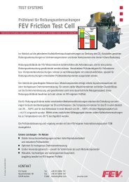
<strong>Variable</strong> compression ratio is the key to realize a higher<br />
degree of downsizing by turbo-charging. The variability allows<br />
high compression ratios in part load with improved efficiency<br />
and low compression ratios at high loads avoiding<br />
knocking and high peak pressures. Starting from a naturally<br />
aspirated 4-Cyl.-1.6 l (56 kW/l) engine the CO2 reduction<br />
potential by downsizing to a direct injected 3-Cyl.-1.0l<br />
engine (90 kW/l) with turbocharger, <strong>variable</strong> cam phasing<br />
(intake and exhaust) and cooled exhaust manifold is approximately<br />
12 %. <strong>Variable</strong> compression ratio in combination<br />
with continuously <strong>variable</strong> valve lift can improve CO2<br />
emission in the NEDC cycle by additional 9 %, resulting in<br />
a total CO2 reduction of 20 % compared to the base engine.<br />
Ethanol E85 fuel is especially adequate for downsizing<br />
in combination with high compression ratios due to its<br />
higher octane number of approx. 110 RON and a strong<br />
cooling effect through three times higher vaporization energy.<br />
The conversion to E85 improves the medium part<br />
and high load and thus achieves a better fuel consumption<br />
in emission test relevant area and in practical driving. A<br />
further 2.5 % CO2 saving is possible by the conversion of<br />
the engine to Flex Fuel E85 with adapted compression ratios.<br />
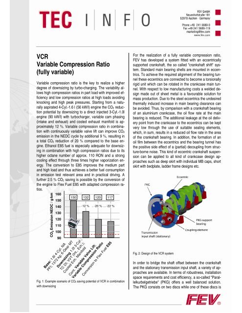
160<br />
CO 2 Emission NEDC / g/km<br />
150<br />
140<br />
130<br />
120<br />
110<br />
100<br />
90<br />
Base: 1.6l 4-Cyl. NA<br />
PFI; 1372 kg; 6-Gear MT<br />
150 132 120<br />
-12 %<br />
Downsizing 1.0l 3-Cyl.;<br />
TC DI; VVT (Int., Exh.);<br />
Cooled Exh. Manifold<br />
-20 %<br />
Cont. <strong>Variable</strong> Valve Lift;<br />
<strong>Variable</strong> <strong>Compression</strong> <strong>Ratio</strong><br />
117<br />
-22 %<br />
Conversion to Flex Fuel E85<br />
Fig. 1: Example scenario of CO2 saving potential of <strong>VCR</strong> in combination<br />
with downsizing<br />
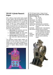
For the realization of a <strong>fully</strong> <strong>variable</strong> compression ratio,<br />
FEV has developed a system fitted with an eccentrically<br />
supported crankshaft, the so called "crankshaft shift" system.<br />
Standard main bearing shells are mounted in eccentrics.<br />
To achieve the required alignment of the bearing tunnel<br />
these eccentrics are connected to become a torsionally<br />
rigid unit which can be rotated in the crankcase main tunnel.<br />
With respect to low manufacturing costs a welded design<br />
made out of sheet metal is a favourable solution for<br />
mass production. Due to the steel eccentrics the undesired<br />
thermally induced increase in main bearing clearance can<br />
be avoided. Thus, by comparison with a crankshaft bearing<br />
of an aluminium crankcase, the oil flow rate at the main<br />
bearing is reduced. The additional leakage at the oil delivery<br />
point from the crankcase to the eccentrics can be kept<br />
very low through the use of suitable sealing elements,<br />
which, in sum, results in a reduced oil flow rate in the area<br />
of the crankshaft bearing. In addition, the formation of an<br />
oil film between the eccentrics and the bearing tunnel has<br />
the positive side effect of a (partial) decoupling from structure-borne<br />
noise. This kind of eccentric crankshaft suspension<br />
can be applied to all kind of crankcase design approaches<br />
such as deep skirt with individual MB caps, short<br />
skirt with bedplate, ladder frame designs etc.<br />
Fig. 2: Design of the <strong>VCR</strong> system<br />
In order to bridge the shaft offset between the crankshaft<br />
and the stationary transmission input shaft, a variety of approaches<br />
are available. In terms of robustness, installation<br />
space requirements and cost efficiency, a so-called "Parallelkurbelgetriebe"<br />
(PKG) offers a well balanced solution.<br />
The PKG consists on two discs while one of these discs is
olted to the crankshaft flange and the other disc is stationary<br />
suspended and is aligned to the transmission input<br />
shaft by means of a support bearing. The torque transmission<br />
from the moved to the stationary disc is realized by<br />
multiple coupling elements (eccentrics) equally spaced on<br />
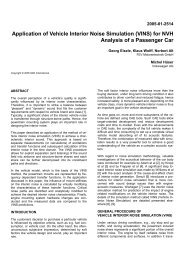
a circle. One of the main development goals is to reduce<br />
the frictional losses induced by the PKG and to achieve durability<br />
targets at the same time. By means of intensive<br />
component testing, it was possible to identify the major<br />
sources of friction losses, and an optimization of the PKG<br />
with regard to friction behaviour was success<strong>fully</strong> performed.<br />
Fig. 3: Progress in PKG friction reduction<br />
As a result the thermodynamic savings are reduced by<br />
only 1 % (example upper class vehicle in the NEDC) due<br />
to the remaining PKG friction. By means of a 500 h durability<br />
run under full load condition the robustness of the latest<br />
friction optimized PKG design was confirmed success<strong>fully</strong><br />
w/o facing any abnormal wear or fatigue problems.<br />
To realize a power take-off for the timing drive, the oil<br />
pump, the accessory drive and eventually a mass balance<br />
drive FEV has developed a variety of solutions such as a<br />
small PKG at the front end, a combined power take-off with<br />
the main PKG or a <strong>variable</strong> chain drive which is capable to<br />
handle a moving crankshaft position. The right concept depends<br />
on the given or intended engine architecture with its<br />
individual needs and constraints to be considered.<br />
For the actuation also different layouts were investigated.<br />
While in early prototype stages a support of the eccentric<br />
moment was realized by a pinion shaft being engaged with<br />
each eccentric, latest designs consist on a worm gear<br />
stage which is engaged only at one cylinder. Due to the<br />
self locking character of the worm gear stage no electric<br />
energy is needed to keep the position. The generation of<br />
the required actuation torque is realized by an electric DC-<br />
Motor with a reduction gear set.<br />
FEV has applied this <strong>VCR</strong> system to many different engine<br />
architectures of its customers within the last years. All the<br />
individual design solutions were confirmed by intensive<br />
CAE and testing activities. As a result this <strong>VCR</strong> system has<br />
reached a high level of maturity up to now and can be considered<br />
as a reliable basis for a series application.<br />
Contact: Dr.-Ing. Karsten Wittek<br />
FEV GmbH<br />
Neuenhofstraße 181<br />
52078 Aachen, Germany<br />
Phone: +49 241 5689-9984<br />
Fax: +49 241 5689-9950<br />
I-Fax: +49 241 5689-7-9984<br />
E-Mail: wittek@fev.com<br />
Internet: http://www.fev.com<br />
Status: 28.09.2010