
You also want an ePaper? Increase the reach of your titles
YUMPU automatically turns print PDFs into web optimized ePapers that Google loves.
SS<br />
S<br />
SS<br />
S<br />
III<br />
O OO<br />
N NN<br />
T TT<br />
III<br />
A AA<br />
N NN<br />
III<br />
M MM<br />
EE<br />
E<br />
DD<br />
D<br />
IM<br />
P<br />
R<br />
O<br />
V C<br />
E<br />
D P<br />
AP<br />
LI<br />
A<br />
T<br />
I<br />
O<br />
CC COL OL OLLL LECT ECT<br />
ECTION ION ION<br />
N<br />
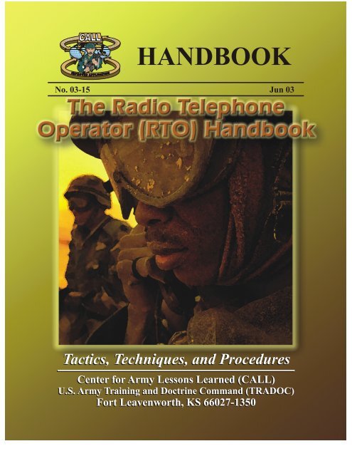
HANDBOOK<br />
No. 03-15 Jun 03<br />
Tactics, Techniques, and Procedures<br />
Center for Army Lessons Learned (CALL)<br />
U.S. Army Training and Doctrine Command (TRADOC)<br />
Fort Leavenworth, KS 66027-1350
FOREWORD<br />
The Joint Readiness Training Center (JRTC), Center for Army Lessons Learned (CALL) cell<br />
compiled this handbook from extracts of technical manuals, lesson outlines from the U.S. Army<br />
Signal School, and unit standing operating procedures (SOPs). Other references include, but are<br />
not limited to, field manuals, quick reference cards, manufacturers' web sites, and interviews<br />
with signal personnel. The purpose of the radio telephone handbook is to provide a quick<br />
reference guide for <strong>RTO</strong>s to support successful mission accomplishment. Supporting leaders<br />
with reliable communications is a direct result of detailed planning, Soldiers' lives hinge on our<br />
ability to plan tactical operations. Communications must support the scheme of maneuver and be<br />
synchronized and integrated to put maximum focus on a specific objective at a specific time to<br />
ensure the leader accomplishes the mission. Today's battlefield is three-dimensional and signal<br />
operations require the same application of thought. Soldiers must understand the requirements<br />
for success in a tactical environment and leaders must keep soldiers informed and updated on all<br />
key information.<br />
MICHAEL A. HIEMSTRA<br />
COL, FA<br />
Director, Center for Army Lessons Learned
Foreword<br />
The Radio Telephone Operator (<strong>RTO</strong>) <strong>Handbook</strong><br />
TABLE OF CONTENTS<br />
Chapter 1: User Information and References 1<br />
Chapter 2: Compromise Procedures 7<br />
Chapter 3: Operator Tasks 11<br />
Chapter 4: Net Control Station (NCS) Tasks 21<br />
Chapter 5: Precision Lightweight Global Positioning Receiver System<br />
(PLGR) Tasks<br />
Chapter 6: Automated Net Control Device (ANCD) Tasks 45<br />
Chapter 7: <strong>RTO</strong> Packing List and Checklist 51<br />
Chapter 8: Preventive Maintenance Checks and Services (PMCS) for<br />
Advanced Systems Improvement Program (ASIP) Radio<br />
Chapter 9: Troubleshooting Guide 57<br />
Chapter 10: Field Expedient Antennas 61<br />
Chapter 11: Advanced Systems Improvement Program (ASIP) Radio<br />
Ranges and Battery Usage<br />
Appendix A: Julian Date Calendar 67<br />
Appendix B: World Time Chart (Time Conversion Table) 69<br />
Appendix C: Radio Frequency Spectrum 71<br />
Appendix D: Glossary 73<br />
Conclusion 77<br />
Note: This handbook contains numerous acronyms tailored to <strong>RTO</strong><br />
procedures and equipment. Refer to the Glossary for a definition of the<br />
acronyms.<br />
<strong>RTO</strong> HANDBOOK<br />
33<br />
53<br />
63<br />
i
CENTER FOR ARMY LESSONS LEARNED<br />
CENTER FOR ARMY LESSONS LEARNED<br />
Director Colonel Michael A. Hiemstra<br />
Managing Editor Mr. Ge<strong>org</strong>e Mordica<br />
Editor, Layout, and Design Valerie Tystad<br />
Graphics and Cover Catherine Elliott<br />
Project Manager/Author Sergeant First Class Robert Ehrlich<br />
Project Analysts Mr. Ralph Nichols<br />
Mr. Tom Odom<br />
The Secretary of the Army has determined that the publication of this periodical is<br />
necessary in the transaction of the public business as required by law of the Department.<br />
Use of funds for printing this publication has been approved by Commander, U.S. Army<br />
Training and Doctrine Command, IAW AR 25-30.<br />
Unless otherwise stated, whenever the masculine or feminine gender is used, both are<br />
intended.<br />
ii<br />
LOCAL REPRODUCTION OF THIS NEWSLETTER IS AUTHORIZED AND<br />
ENCOURAGED.
CHAPTER 1<br />
USER INFORMATION AND REFERENCES<br />
This chapter provides a compendium of basic user information and references necessary for all<br />
<strong>RTO</strong>s. It is not a complete guide to SINCGARS or <strong>RTO</strong> duties. Rather it is a start point and a<br />
handy reference for any soldier who may be tasked with <strong>RTO</strong> duties. Because the <strong>RTO</strong> is the<br />
small unit leader’s walking, talking tactical operations center, this chapter also provides a similar<br />
start point for unit leaders, from team to battalion, who need to be familiar with the SINCGARS<br />
and <strong>RTO</strong> duties.<br />
1. REFERENCES.<br />
a. TM 11-5820-890-10-8, Operators Manual, SINCGARS Ground Combat Net Radio,<br />
ICOM.<br />
b. TM 11-5820-890-10-6, SINCGARS ICOM Ground Radios Operator’s Pocket Guide.<br />
c. TM 11-5820-890-10-7, SINCGARS ICOM Ground Radios NCS Pocket Guide.<br />
d. FM 11-32, Combat Net Radio Operations.<br />
e. TM 11-5825-291-13, Satellite Signals Navigation Sets.<br />
f. TB 11-5825-291-10-3, The PLGR Made Simple.<br />
g. TB 380-41 (Change 1), Procedures for Safeguarding, Accounting and Supply<br />
Control of COMSEC Material.<br />
2. PURPOSE. This guide establishes procedures, guidelines, and information on operating the<br />
SINCGARS radio system. It is designed to supplement unit level <strong>RTO</strong> training and certification<br />
and act as a quick reference for <strong>RTO</strong>s when faced with a communications problem.<br />
3. GENERAL.<br />
<strong>RTO</strong> HANDBOOK<br />
a. SINCGARS ASIP is a “user owned and operated” solid-state frequency modulated<br />
(FM) combat net radio (CNR), that operates in the 30.000 to 87.995 MHZ frequency<br />
range in the single channel (SC) or frequency hopping (FH) mode. The ASIP replaces the<br />
RT-1523A and RT-1523B model SINCGARS. The ASIP is compatible with the older<br />
SINCGARS and with NATO forces in SC, squelch off mode. It provides electronic<br />
warfare (EW) protection and a reduced electromagnetic signature in the FH mode.<br />
b. The AN/CYZ-10 automated net control device (ANCD) is a hand-held device capable<br />
of receiving, storing, and transferring data between ANCDs, or between ANCD and an<br />
ASIP radio. The primary application for this device is to fill the ASIP with FH data, time,<br />
communications security (COMSEC), and loadset information. ANCDs are<br />
non-repairable controlled cryptographic items (CCI) and must be stored IAW TB 340-1<br />
(change 1). Loaded ANCD with “Secret” information must be stored in a 3-combination<br />
safe. ANCDs that are not loaded must be secured with no less than two barrier protection,<br />
i.e. a locked door and wall locker using a 200 series lock.<br />
1
CENTER FOR ARMY LESSONS LEARNED<br />
c. The AN/PSN-11 precision lightweight global positioning system receiver (PLGR) is a<br />
hand-held Global Positioning System (GPS). The primary application for this device is<br />
precision position location and land navigation via programmable waypoints. The<br />
secondary application for this device is to update and verify the date and time in the ASIP<br />
radio. The PLGR is a high dollar item and should be safeguarded accordingly.<br />
d. The ASIP and ANCD are CCI and require double-barrier protection IAW DA PAM<br />
25-380-2. All unattended ASIP radios will be zeroed. Radios will be reloaded when<br />
required using the ANCD.<br />
e. Maintenance procedures are the same for the older SINCGARS radio. The ASIP is<br />
accountable by serial number. When the RT-1523E has been determined non-mission<br />
capable (NMC) by unit-level maintenance personnel, it will be turned in to the forward<br />
support battalion (FSB), direct support unit (DSU) for repairs. The DSU will then<br />
determine if the radio will be replaced or held for repair in the shop. A property book<br />
transaction (lateral transfer) is required should the radio be exchanged for a working<br />
RT-1523F. Only company communications chiefs and/or <strong>RTO</strong>s will turn-in equipment to<br />
the battalion communications section.<br />
4. OPERATING PROCEDURES.<br />
2<br />
a. Net synchronization time (NET).<br />
(1) The ASIP has an internal master clock. Each channel (1 through 6) also has<br />
the ability to maintain separate time. Time is primarily loaded into the ASIP via<br />
the ANCD and alternately the PLGR. If the ANCD is used, ensure the time in the<br />
ANCD has accurate ZULU time stored. GPS ZULU time is the standard time<br />
zone used for all division radios.<br />
(2) The ZULU time stored in an ANCD will drift significantly over time and if<br />
loaded into the ASIP will not allow communications with other net members. All<br />
<strong>RTO</strong>s must verify accurate time in the ASIP after loading their radios. All <strong>RTO</strong>s<br />
must also maintain accurate time (hour, minute, and seconds) on a digital watch to<br />
quickly verify time. Time must be within + or – 4 seconds to communicate with<br />
other ASIPs. Accurate ZULU time can be obtained by the following methods:<br />
(a) Calling the atomic clock – DSN 763-1401 Commercial (202) 763-1401<br />
(b) Via PLGR (must be + or – 1 second)<br />
(c) Top of the hour on any 5 kHz frequency via HF radios (PRC-104).<br />
(3) Julian date (JD). The ASIP JD is the last two digits of the full Julian date. See<br />
Appendix A (Julian date calendar) for the correct Julian date. The JD is also<br />
automatically loaded via the ANCD. If a net member loads the incorrect JD or<br />
accidentally changes the JD, all communications with other net members will be<br />
lost.<br />
(4) During FH operations, the net control station (NCS) will always maintain<br />
accurate time and will operate a radio in the frequency hop master (FH-M) mode.<br />
The NCS for each net is the only radio authorized to operate in the FH-M mode.<br />
This will ensure time accuracy throughout the net. Should the NCS radio fail
during any part of the mission, the alternate NCS will switch his radio to the<br />
FH-M mode.<br />
b. Initial net opening. The battalion standard is Hot Start net opening procedure. The<br />
procedure is covered in Chapter 3 (Operator Tasks).<br />
c. Passive late net entry. This procedure allows a radio with correct hop set and<br />
COMSEC information but inaccurate time (+ or – 59 seconds) to enter a net. The<br />
procedures are covered in Chapter 3 (Operator Tasks).<br />
d. Loadset.<br />
(1) Loadsets are made up of the following components:<br />
(a) TranSec key (TSK) – frequency hop data<br />
(b) Esets – net IDs (example F302)<br />
(c) COMSEC keys (TEK and KEK) – transmission encryption keys<br />
(d) Lockout sets – restricted frequencies within the frequency hop data.<br />
(2) The ANCD transfers a loadset to an ASIP radio. This loadset is transferred by<br />
a menu-driven procedure during normal loading procedures of the ASIP with the<br />
ANCD.<br />
(3) Net IDs are normally fixed and will follow the numbering scheme listed<br />
below. Specific net IDs within the below listed ranges are designated in the signal<br />
operating instructions (SOI).<br />
Note: These are sample division standards only and may change for real<br />
world contingencies or deployments<br />
FH000-099 Theater/Joint<br />
FH100-299 Corps/Service<br />
FH300-399 (1st BDE)<br />
FH400-499 (2nd BDE)<br />
FH500-599 (3rd BDE)<br />
FH600-699 (AVN BDE)<br />
FH700-799 (DIVARTY)<br />
FH800-899 (DISCOM)<br />
FH900-999 (DIV HQs)<br />
<strong>RTO</strong> HANDBOOK<br />
e. Operational security (OPSEC). OPSEC is defined as any measure an operator takes in<br />
order to safeguard information from the enemy. OPSEC can be anything from<br />
3
CENTER FOR ARMY LESSONS LEARNED<br />
4<br />
minimizing the number of net IDs loaded into a radio, to zeroing an ANCD or radio if<br />
capture by the enemy is imminent, thereby denying the enemy the ability to exploit the<br />
ANCD or radio for intelligence against U.S. Forces. All personnel assigned to, attached<br />
to, or under the operational control of the battalion will follow these procedures to<br />
maximize OPSEC.<br />
(1) Loadsets contain only the primary net used by the operator. If the <strong>RTO</strong><br />
requires additional nets he will manually load the ASIP with the required net.<br />
Minimize the number of channels used.<br />
(2) ANCDs only contain the loadset and COMSEC required by the operator.<br />
(3) New editions of the signal operating instructions (SOI) and COMSEC should<br />
not be distributed below the battalion level until authorized by the brigade signal<br />
officer (SIGO).<br />
(4) All <strong>RTO</strong>s must know all compromise procedures and codewords prescribed in<br />
Chapter 2 (Compromise Procedures) and understand the steps for each<br />
procedure.<br />
(5) Safeguard any radio cheat sheets that list call signs and net IDs and account<br />
for cheat sheets according to classification (for official use only [FOUO],<br />
classified, secret, etc.). Whenever possible, memorize this information.<br />
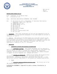
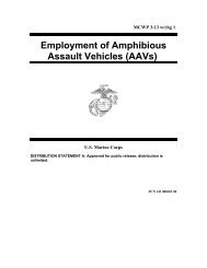
Battery<br />
Latches<br />
SINCGARS Receiver/Transmitter<br />
RT<br />
SINCGARS MANPACK System<br />
Battery<br />
Box<br />
Binding Post<br />
Connector<br />
P1 RT System<br />
Connector<br />
Holding Battery<br />
Decal (Bottom of RT)<br />
Figure 1<br />
SINCGARS Rucksack has<br />
slots in the top flap.<br />
Rucksack Manpack<br />
Antenna<br />
Handset
f. Common prowords: Common prowords are those words that are used on a regular basis<br />
while conducting radio operations. They are NOT interchangeable as the meanings are<br />
specific and clear to the receiver. An example is “Say Again” versus “Repeat.” “Say<br />
Again” means to repeat the last transmission, while “Repeat” is in reference to fire<br />
support to fire the last mission again.<br />
Proword Meaning<br />
ALL AFTER I refer to the entire message that follows…<br />
ALL BEFORE I refer to the entire message that proceeds…<br />
BREAK I now separate the text from other parts of the message.<br />
CORRECTION There is an error in this transmission. Transmission will<br />
continue with the last word correctly transmitted.<br />
GROUPS This message contains the number of groups indicated by the<br />
numeral following.<br />
I SAY AGAIN I am repeating transmission or part indicated.<br />
I SPELL I shall spell the next word phonetically.<br />
MESSAGE<br />
MORE TO FOLLOW<br />
OUT<br />
OVER<br />
A message that requires recording is about to follow.<br />
(Transmitted immediately after the call.) This proword is not<br />
used on nets primarily employed for conveying messages. It is<br />
intended for use when messages are passed on tactical or<br />
reporting net.<br />
Transmitting station has additional traffic for the receiving<br />
station.<br />
This is the end of my transmission to you and no answer is<br />
required or expected.<br />
This is the end of my transmission to you and a response is<br />
necessary. Go ahead: transmit.<br />
RADIO CHECK What is my signal strength and readability, i.e. How do you hear<br />
me?<br />
ROGER<br />
<strong>RTO</strong> HANDBOOK<br />
I have received your last transmission satisfactorily, radio check<br />
is loud and clear.<br />
SAY AGAIN Repeat all of your last transmission. Followed by identification<br />
data means “repeat - (portion indicated).”<br />
5
CENTER FOR ARMY LESSONS LEARNED<br />
THIS IS This transmission is from the station whose designator immediately<br />
follows.<br />
6<br />
TIME That which immediately follows is the time or date-time group of the<br />
message.<br />
WAIT I must pause for a few seconds.<br />
WAIT-OUT I must pause longer than a few seconds.<br />
WILCO I have received your transmission, understand it, and will comply, to<br />
be used only by the addressee. Since the meaning of ROGER is<br />
included in that of WILCO, the two prowords are never used together.<br />
WORD AFTER I refer to the word of the message that follows.<br />
WORD BEFORE I refer to the word of the message that precedes.
CHAPTER 2<br />
COMPROMISE PROCEDURES<br />
Compromise of sensitive signal information, like death and taxes, is inevitable and always<br />
unwelcome. Still the effects of compromise can be minimized through common sense<br />
precautions and standardized corrective measures embedded in unit SOPs. The operative word in<br />
dealing with compromise is a common understanding of those procedures based on repetitive<br />
drills. This chapter offers a possible template for units in establishing compromise procedures.<br />
But remember like all such standardized procedures, this SOP is absolutely worthless if not<br />
practiced and understood by all in a unit.<br />
1. PURPOSE. This chapter establishes procedures, guidelines, and information on compromise<br />
procedures. It is designed to standardize the process for executing compromise procedures. The<br />
compromise procedures reflect the steps used by the division and brigade.<br />
2. GENERAL. A compromise is defined as any COMSEC fill device or COMSEC-filled and<br />
functioning radio that falls into enemy hands before the operator can zero the device. The<br />
procedures listed below detail actions to take to minimize compromises, actions to take if a<br />
compromise is imminent, and actions to take after a net becomes compromised.<br />
3. PROCEDURES.<br />
a. Minimizing compromise<br />
(1) ANCDs are not distributed below the infantry company headquarters or below<br />
antitank platoon headquarters level. Combat multipliers will not deploy with<br />
ANCDs and will receive all radio fills from the maneuver element they are<br />
supporting. Ensure all CCI is properly accounted for and secured at all times.<br />
(2) Signal operation instructions (SOI) data is not distributed below battalion<br />
level. The new challenge and password is announced over a secure command net<br />
daily at 0001 hours (ZULU).<br />
(3) All command vehicles leaving the tactical operation center (TOC) or<br />
headquarters command post secure their ANCDs at that TOC or command post<br />
(CP).<br />
(4) Excess ANCDs within a deployed unit are zeroed.<br />
b. If compromise is imminent<br />
<strong>RTO</strong> HANDBOOK<br />
(1) If carrying an ANCD, the operator immediately zeroes the ANCD by hitting<br />
the red zero key four times, then removes the COMSEC encryption key (CIK)<br />
and destroys it. By destroying the ANCD’s CIK, the ANCD is inoperable.<br />
(2) Operators announce on the radio, “ALL STATIONS THIS NET, THIS IS<br />
(call sign) WATERGATE, WATERGATE, WATERGATE!” and then<br />
immediately zero the COMSEC by turning the function knob to “Z.” This<br />
message alerts other net members that you have zeroed your radio’s COMSEC<br />
7
CENTER FOR ARMY LESSONS LEARNED<br />
8<br />
because you are being captured. You may still use the radio, but only in a<br />
non-secure mode, until you can receive another ANCD fill.<br />
c. After a compromise<br />
(1) If you suspect a net is compromised DO NOT announce over the net, “THIS<br />
NET IS COMPROMISED!” Use an alternate secure net to notify your higher<br />
headquarters and/or announce over the net, “ALL STATIONS THIS NET, THIS<br />
IS (call sign) RED EYE, RED EYE, RED EYE!” This message alerts other net<br />
members that you suspect the net is compromised and all classified traffic must<br />
come to a halt.<br />
(2) Compromised nets continue to operate on the compromised traffic encryption<br />
key (TEK) until the net control station (NCS) directs a change of the TEK or net<br />
ID. The directive will only come from the battalion signal officer.<br />
(3) Once the mission allows, the NCS directs a net ID or TEK change using the<br />
following codewords:<br />
Net ID<br />
RATTLESNAKE 1: Change to STRIKE NET 1<br />
RATTLESNAKE 2: Change to STRIKE NET 2<br />
RATTLESNAKE 3: Change to original NET ID<br />
An alternate method is to change the Julian date (JD) on the radio net using<br />
codewords and leaving the net ID alone. Example:<br />
Julian Date<br />
WARRIOR SPIRIT 1: Change JD + 3<br />
WARRIOR SPIRIT 2: Change JD + 5<br />
WARRIOR SPIRIT 3: Change JD + 7<br />
(4) The NCS directs over-the-air-rekey (OTAR) using either the automatic remote<br />
keying (AK) method or manual remote keying (MK) method. The procedures for<br />
both tasks are covered in Chapter 4 (NCS Tasks). Once either method is executed,<br />
the NCS makes a radio check with all net members. An alternate NCS acts as a<br />
“sweeper” and remains on the old net ID or TEK until all members are notified<br />
and comply with the change.<br />
(5) Actual STRIKE net IDs are found in the SOI and must be memorized.<br />
STRIKE net IDs WILL NOT BE WRITTEN DOWN ANYWHERE.<br />
(6) Once the new net is established, it is clear for classified traffic again.
(7) Codewords used to initiate change of SOI editions are as follows:<br />
SOI<br />
COBRA: Change to B edition TEK/SOI<br />
PYTHON: Change to C edition TEK/SOI<br />
COTTONMOUTH: Change to original TEK/SOI<br />
(8) The battalion has the capability to send new SOI information electronically<br />
via the ASIP and ANCD using the broadcast method. The battalion will only use<br />
this method as a last resort if other means of disseminating the SOI information<br />
proves impossible or impractical. The broadcast method is a very time intensive<br />
process because the ANCD will only process data at a 16 kb/s rate and normally<br />
allows units to receive one time period at a time. The procedure includes a polling<br />
feature which allows the NCS to determine by automatic query if up to 16 net<br />
members (designated by special ID numbers) did or did not receive the SOI<br />
information sent by broadcast.<br />
(a) The following list assigns polling ID numbers for each net member:<br />
Unit/Section Polling #<br />
A Co 1<br />
B Co 2<br />
C Co 3<br />
D Co 4<br />
ALOC 5<br />
CBT TRNS 6<br />
Retrans 7<br />
<strong>RTO</strong> HANDBOOK<br />
(b) SOI broadcast can handle up to 16 polling numbers. Polling numbers<br />
8-16 will only be assigned when required.<br />
9
CHAPTER 3<br />
OPERATOR TASKS<br />
<strong>RTO</strong> HANDBOOK<br />
The <strong>RTO</strong>, like any other soldier, has a standard set of tasks to accomplish in training and actual<br />
operations. For the practiced <strong>RTO</strong>, such tasks become almost second nature, especially those<br />
tasks that are daily requirements. On occasion even an experienced operator may need to refresh<br />
his/her memory when a less practiced requirement pops up. For less experienced <strong>RTO</strong>s, the need<br />
for a standard list of tasks is self-evident. This chapter offers all <strong>RTO</strong>s, both experienced and<br />
novice, a standard list of tasks and a quick guide on how they are accomplished.<br />
PURPOSE. To provide operators of ASIP radios with a quick reference to assist in task<br />
performance during training and operations. Using this <strong>RTO</strong> handbook, the properly trained<br />
ASIP operator should be able to perform, without assistance, all operator tasks.<br />
Task 1 (Load SC Frequency into ASIP): The ASIP operator is required to perform this<br />
task in preparation for the employment of single channel communications, use of the<br />
CUE (key the radio) and ERF (electronic remote fill) methods of late net entry, and for<br />
single channel frequency updates. The operator determines the required frequencies from<br />
the ANCD or another source. These frequencies are then loaded into the radio by use of<br />
the receiver-transmitter (RT) keyboard.<br />
Task 2 (Load COMSEC/FH Data/Sync Time using the ANCD): This task is required<br />
in preparation for a Hot Start net opening and, without sync time, for COMSEC/FH data<br />
updates. Performance of this task involves the use of an ANCD as a source of COMSEC<br />
keys, FH data (hopset, TSK, and net ID), and sync time. By use of the ICOM fill<br />
procedure, COMSEC, FH data, and sync time are simultaneously loaded into all six<br />
channels of the ASIP radio. Upon completion of the ICOM fill, the radio is fully prepared<br />
for secure, frequency hopping communications.<br />
Task 3 (Perform Hot Start Net Opening): This task is required when the net has been<br />
down for any reason and is to become operational at a prescribed time. This task involves<br />
loading the radio with COMSEC keys, FH data, and sync time by use of the ICOM fill<br />
procedure (See Operator Task 2) and calling the NCS in secure frequency hopping mode<br />
to request net entry.<br />
Task 4 (Perform Passive Late Net Entry): This task is required when the sync time in<br />
your radio becomes more than 4 seconds (plus or minus), but less than one minute,<br />
different from net sync time. Passive late net entry enables an individual operator to<br />
re-enter the net without action on the part of the NCS or other net operators. This task<br />
makes use of a feature built into the ASIP radio and involves two steps: placing the RT in<br />
passive late net entry mode and waiting for the radio to adjust its sync time to that of the<br />
net. When this method of late net entry does not work, the Hot Start procedure or CUE<br />
and ERF method of late net entry should be used.<br />
Task 5 (Receive Net Update ERF from NCS): This task is performed when there is a<br />
requirement to change or update some element of FH data and the operational situation<br />
makes it impossible or impractical to disseminate the new data by physical connection of<br />
ANCD to ANCD. In such cases, the NCS alerts net operators that they are to receive a<br />
net update ERF. Operators then change the RT FCTN from SQ ON to LD, remaining on<br />
the operational channel. The NCS sends the ERF on the operational channel (not on<br />
11
CENTER FOR ARMY LESSONS LEARNED<br />
12<br />
MAN as during a Cold Start net opening). Once the net update ERF has been sent, the<br />
new data may be made effective immediately or stored for later implementation. (ERF,<br />
broadcast, and OTAR communications).<br />
Task 6 (Perform CUE and ERF Late Net Entry (LNE): This task may be required<br />
when a radio has been out of the net for some period or has lost its sync time. The<br />
preferred action is to try passive late net entry first (See Operator Task 4). This method<br />
requires the operator to load CUE and MAN frequencies, “cue” the NCS in plain text<br />
(PT), repeat the “cue” until a response is received, switch COMSEC to cipher text (CT)<br />
to receive the NCS response, use single channel mode, and receive and store an ERF<br />
when it is sent. (A simpler method of re-entering the net when the passive method does<br />
not work is the Hot Start procedures (See Operator Task 3).<br />
Task 7 (Change Net ID): This operator task is performed when there is a requirement to<br />
communicate with a net or station that is not a part of the operational loadset or loadsets,<br />
if more than one radio is being used. Commanders, staff officers, drivers, and others who<br />
frequently move about the battlefield should be able to perform this task without<br />
assistance. Use of this procedure enables the operator to contact virtually any<br />
SINCGARS net within division.
PREPARATION TASK 1: Preparation Settings from MENU<br />
SUBTASKS ACTION RESULT<br />
a. Set RT Volume 1. Press MENU<br />
2. Press Digit (1-9) for VOL<br />
Setting (0) for Whisper Mode<br />
b. Set RTChannel 1. Press MENU (until<br />
CHAN)<br />
2. Press Digit (1-6) for<br />
Channel desired: (0) for<br />
MAN, (7) for CUE<br />
c. Set RT Mode 1. Press MENU (until PWR)<br />
2. Press CHG for desired<br />
PRW setting<br />
d. Set RT Mode 1. Press MENU (until<br />
MODE)<br />
2. Press CHG for desired<br />
MODE<br />
e. Set COMSEC 1. Press MENU (until CMSC)<br />
2. Press CHG for desired<br />
CMSC setting<br />
f. Set Backlight 1. Place RT in SQ ON<br />
2. Press FREQ/Backlight<br />
3. Press CHG until desired<br />
setting<br />
Press MENU to display VOL<br />
level<br />
Display reads WHSP if 0<br />
selected<br />
Display reads (1-6), (Q) for<br />
CUE, (M) for Manual<br />
Display reads (LO, M, HI,<br />
PA)<br />
Display reads (SC, FH, FHM)<br />
Display reads (PT, CT, TD,<br />
RV)<br />
Backlight lights (4 settings<br />
Low to High, then OFF)<br />
Default settings are: VOL (5), CHAN (1), PWR (LO), MODE (FH), COMSEC (CT).<br />
<strong>RTO</strong> HANDBOOK<br />
13
CENTER FOR ARMY LESSONS LEARNED<br />
OPERATOR TASK 1: Load Single Channel Freq into ASIP<br />
SUBTASKS ACTION RESULT<br />
a. Prepare to perform task 1. Obtain proper freq from<br />
ANCD<br />
2. Set RT controls:**<br />
COMSEC to PT<br />
Mode to SC<br />
FCTN to Z-FH, TST, and<br />
then to LD<br />
CHAN to MAN, CUE, or<br />
1 - 6<br />
(Load CUE freq only if<br />
directed) *<br />
RT display shows "GOOD"<br />
(or see unit maintainer)<br />
b. Load SC Freq 1. Press: [FREQ] Display shows [00000] or<br />
[30000]<br />
2. Press: [CLR] Display shows [_____]<br />
3. Enter 5-digits SC freq. Display shows SC [XXXXX]<br />
c. Store SC freq. Press STO (within 7 sec) Display blinks once (data is<br />
stored)<br />
d. Prepare to communicate 1. Repeat: Step b-1 for each<br />
freq needed<br />
*Only NCS and Alt NCS will load a CUE frequency.<br />
**RT settings for ASIP are set via MENU.<br />
14<br />
(As directed by NCS or unit<br />
SOP)<br />
2. Set: FCTN to SQ ON Loading of SC freq is<br />
complete
OPERATOR TASK 2: Load COMSEC/FH Data/Synch Time using the ANCD*<br />
1. Select: SOI Radio Supervisor<br />
2. Send Receive Database; set up COMSEC Time<br />
3. Send to: Radio ANCD Stu Pc<br />
4. Select: iCom Nonicom Abn Rcu Haveq<br />
5. Connect to RT AUD/FILL Connector [ ]<br />
6. Set FCTN switch to LD on RT [ ]<br />
7. Do you want to include time? (Y/N)<br />
8. Press [LOAD] on RT<br />
9. Transfer in progress/Transfer successful<br />
• The ICOM fill procedure loads the radio with COMSEC keys, FH data, and synch time<br />
for all six ASIP channels.<br />
• Select “RCU” to fill an RCU with COMSEC keys. Procedure is the same as that<br />
shown for “ICOM”.<br />
• Throughout this manual, when [ ] appears in the lower right corner of a screen, you<br />
must press the down arrow on ANCD to proceed.<br />
• Load time as part of ICOM fill during net openings and Hot Start late net entry only,<br />
not net updates.<br />
• RT settings for ASIP are set via MENU.<br />
<strong>RTO</strong> HANDBOOK<br />
15
CENTER FOR ARMY LESSONS LEARNED<br />
OPERATOR TASK 3: Perform Hot Start Net opening<br />
SUBTASKS ACTION RESULT<br />
Load RT with COMSEC/FH,<br />
date, and time*<br />
(See Operator Task 2 for<br />
ICOM fill)<br />
Enter net Call NCS in CT, FH and<br />
request to enter net<br />
COMSEC/FH data and time<br />
load into all 6 channels of the<br />
RT<br />
Hot Start net opening is<br />
complete*<br />
*All ASIP radios will accept time from an ANCD as part of a load set and from a PLGR as a<br />
separate loading of time.<br />
OPERATOR TASK 4: Perform Passive Late Net Entry (LNE)<br />
SUBTASKS ACTION RESULT<br />
Use passive method of late<br />
net entry<br />
(1) Press:<br />
FREQ<br />
SYNC<br />
(2) Wait for radio traffic to be<br />
heard<br />
(Do not press PTT)<br />
Display shows [F XXX]<br />
Display shows [LF XXX]<br />
Display shows [F XXX] (“L”<br />
is dropped)<br />
(3) Call NCS and re-enter net Passive LNE is complete*<br />
*If traffic is not heard for three minutes or more after using passive late net entry method, use<br />
the Hot Start procedure or CUE and ERF method. DO NOT KEY THE HANDSET WHILE IN<br />
THE PASSIVE LATE NET ENTRY MODE, IT WILL THROW YOUR SYNC TIME OFF.<br />
16
OPERATOR TASK 5: Receive Net Update ERF from NCS<br />
SUBTASKS ACTION RESULT<br />
Prepare to receive net update<br />
operational channel<br />
(1) Stay on net N/A<br />
(2) Set: FCTN to LD N/A<br />
Receive and store net update (1) Standby for NCS to send<br />
ERF<br />
(2) Note Signal Display<br />
Activation<br />
Check communications 1) Set: CHAN to X<br />
N/A<br />
Display shows [HF XXX]<br />
Press: STO Display shows [STO ]<br />
Enter: X (1 – 6)* Display shows [STO X];<br />
blinks<br />
FCTN to SQ ON<br />
N/A<br />
(2) Call or respond to NCS Net update ERF is<br />
complete**<br />
<strong>RTO</strong> HANDBOOK<br />
*NCS will direct the channel for storage of ERF. When update becomes effective, this channel<br />
becomes new net operational channel.<br />
**It is assumed that the operator had the same COMSEC key loaded in channels 1 thru 5.<br />
17
CENTER FOR ARMY LESSONS LEARNED<br />
OPERATOR TASK 6: Perform CUE and ERF Late Net Entry<br />
SUBTASKS ACTION RESULT<br />
Use CUE and ERF Method of<br />
LNE*<br />
1. Load CUE freq (and MAN<br />
if not loaded<br />
See Operator Task 1<br />
2. Set COMSEC to PT RT must be in PT to send<br />
CUE<br />
3. Press PTT (4-5 sec) Press PTT, but do not talk<br />
4. Set (at once ) COMSEC to<br />
CT<br />
5. Wait for answer N/A<br />
6. Repeat every 15 seconds<br />
until NCS answers<br />
7. Request NCS send you an<br />
ERF<br />
8. Receive & store ERF<br />
when sent<br />
NCS/Alt NCS will answer in<br />
CT<br />
CUE goes through only if net<br />
is quiet<br />
Go to MAN when NCS<br />
directs<br />
See Operator Task 4<br />
9. Re-enter: net CUE & ERF LNE is<br />
complete<br />
*An operator having a loaded ANCD and access to GPS time may elect to re-enter the net by use<br />
of the Hot Start procedure.<br />
18
OPERATOR TASK 7: Change Net ID<br />
SUBTASKS ACTION RESULT<br />
Set proper RT controls Set * FCTN to LD<br />
CHAN to 1-6 (channel in<br />
which data is stored)<br />
Enter new net ID in RT Press:<br />
Resume normal<br />
communications<br />
FREQ<br />
CLR<br />
ID numbers (3)<br />
STO<br />
Set FCTN to SQ ON<br />
CHAN to 1-6 (as desired)<br />
<strong>RTO</strong> HANDBOOK<br />
Display shows: [F XXX]<br />
Display shows: [F ___]<br />
Display shows: [F XXX]<br />
Display blinks; net ID is<br />
stored<br />
New net ID is now available<br />
for use<br />
*The ASIP radio allows a change of all three digits of a net ID with the MODE switch set to FH<br />
or FH-M.<br />
19
CHAPTER 4<br />
NET CONTROL STATION (NCS) TASKS<br />
<strong>RTO</strong> HANDBOOK<br />
Without an effective net control station, a radio net will degenerate rapidly into chaos under the<br />
stress of training. Actual combat only accelerates that process. It is up to NCS to maintain net<br />
procedures and discipline. As in the case with operator tasks, the experienced NCS will know the<br />
routine tasks and be able to perform them without hesitation. For non-routine tasks, the standard<br />
task list provided here should help. Novice NCS personnel will also find this list and “how to”<br />
guide useful.<br />
PURPOSE. To provide net control station (NCS) personnel with quick reference to assist in task<br />
performance during training and operations. Using this <strong>RTO</strong> <strong>Handbook</strong>, properly trained NCS<br />
personnel should be able to perform, without assistance, all NCS tasks.<br />
Task 1 (Conduct Hot Start Net Opening): This task represents a basic NCS<br />
requirement, to open the SINCGARS secure, frequency hopping net. During use of the<br />
Hot Start net opening procedure, NCS responsibilities are primarily supervisory. Each<br />
operator loads the radio with COMSEC keys, FH data, and sync time in preparation for<br />
the net opening. Upon completing the ICOM fill, the operator merely calls the NCS in<br />
secure, FH mode and requests permission to enter the net. NCS requirements are limited<br />
to ensuring that operations are provided the required data for net opening and respond to<br />
operator requests for net entry.<br />
Task 2 (Respond to CUE Calls): An important feature of the SINCGARS radio is its<br />
ability to be contacted by a non-frequency hopping radio, or an HF radio lacking data or<br />
sync time, through a process known as “CUEing.” To CUE, set the calling radio on the<br />
prescribed CUE frequency, press the push-to-talk switch, and wait for a response. This<br />
action causes a “CUE” message to appear in the RT display of the NCS and alternate<br />
NCS radio.<br />
Task 3 (Transmit Updated FH Data Via Net Update ERF): This task enables the<br />
NCS to electronically transmit new FH data to net operators when distribution by<br />
physical connection of ANCD to ANCD is impossible or impractical. This procedure<br />
may be used to update (change) hopsets, TSKs, net Ids, and sync time. The task involves<br />
alerting net operators, sending the ERF using the net operational channel, confirming<br />
receipt of the ERF, and making a communications check when the changed FH data is<br />
put into effect.<br />
Task 4 (Transfer SOI Information Using Broadcast Mode): This procedure enables<br />
an NCS to send SOI information electronically to net members wherever updating by<br />
physical connection of ANCD to ANCD proves to be impossible or impractical. The<br />
Broadcast mode requires approximately two minutes to transmit one time period of a<br />
battalion SOI extract. The procedure includes a polling feature that allows the NCS to<br />
determine by automatic query if up to 16 net operators (designated by special ID<br />
numbers) did or did not receive the SOI information sent by Broadcast mode.<br />
Task 5 (Send TEK to other NCSs Using MK Method of OTAR): This procedure<br />
allows an NCS to transfer a TEK (not a KEK) electronically, over-the-air-rekey (OTAR)<br />
to other NCSs. This capability is useful when the tactical situation or terrain makes it<br />
impossible or impractical to pass new TEK by physical connection of ANCD to ANCD.<br />
21
CENTER FOR ARMY LESSONS LEARNED<br />
Receiving NCSs store the new TEK in their ANCDs. The new TEK can then be passed<br />
to operators by physical transfer. NCS Tasks 5 and 7 are performed together by Source<br />
and Target NCSs, respectively.<br />
Task 6 (Receive and Store TEK Sent by MK Method OTAR): This task is performed<br />
by target NCSs when a source NCS electronically transmits a TEK using the MK method<br />
of OTAR. This procedure allows target NCSs to store the new TEK in their ANCDs for<br />
physical distribution to net operators when required. The sending NCS directs receiving<br />
NCSs to perform this task as an integral part of the MK OTAR process. This task<br />
supplements NCS Task 5 above.<br />
Task 7 (Send TEK to Net Operators Using the AK Method of OTAR): This<br />
procedure enables an NCS to transfer electronically a TEK (not a KEK) directly from the<br />
NCS ANCD to net member radios. In the AK method, the TEK transferred to net<br />
member radios automatically, and instantaneously replaces the TEK being used. Also,<br />
the KEK in the net member radio is automatically updated (changed) during the AK<br />
procedure. After sending a TEK by AK OTAR, the source NCS must load the new TEK.<br />
While the AK method of OTAR requires no action on the part of the receiving net<br />
members, it is quite demanding of the source NCS.<br />
NCS TASK 1: Conduct Hot Start Net Opening.<br />
SUBTASKS ACTION RESULT<br />
Load NCS RT with<br />
COMSEC/FH data and time<br />
Load net RTs with<br />
COMSEC/FH data and time<br />
See Operator Task 2 or<br />
ICOM fill procedure<br />
Direct net members to<br />
perform Operator Task 3 (Hot<br />
Start)<br />
Admit members to net Respond to call in FH, CT<br />
mode<br />
*ANCD converts current date to two-digit Julian date.<br />
22<br />
COMSEC/FH data and time<br />
are loaded into all 6 RT<br />
channels*<br />
Net member RTs are prepared<br />
to enter FH, CT net upon<br />
request
NCS TASK 2: Respond to CUE calls.<br />
SUBTASKS ACTION RESULT<br />
Note “CUE" in RT display 1. Switch to CUE channel Caller CUEs in PT, listens in<br />
CT<br />
3. Call CUE caller on CUE<br />
freq, in CT<br />
3. Direct CUEer go to<br />
MAN/CT<br />
4. Determine CUE caller’s<br />
need<br />
5. Provide ERF if appropriate<br />
(NCS Task 3)<br />
6. Return to operational<br />
channel<br />
7. Displace if enemy has DF<br />
capability<br />
<strong>RTO</strong> HANDBOOK<br />
CUE caller gets response<br />
Must have MAN FREQ<br />
loaded in MAN CHAN<br />
If CUEer wishes to enter net<br />
CUE & MAN freq. can be<br />
DF’d<br />
23
CENTER FOR ARMY LESSONS LEARNED<br />
NCS TASK 3: Transmit Updated FH Data Via Net Update ERF.<br />
SUBTASKS ACTION RESULT<br />
Prepare to send net update<br />
ERF<br />
Prepare net operations for net<br />
update ERF<br />
Send net update ERF<br />
Press for 3 sec.<br />
24<br />
1. Obtain updated FH Data;<br />
and effective time<br />
Obtain from SIGO, ANCD,<br />
or SOI as appropriate<br />
2. Load new FH Perform ICOM fill or data<br />
into NCS radio change ESET<br />
in one channel<br />
1. Alert net, update ERF is to<br />
be sent<br />
2. Inform operators what<br />
channel to store ERF<br />
3. Advise operators when<br />
new FH data is effective<br />
Wait until the net is clear of<br />
operational traffic<br />
Facilitates channel change<br />
when data is to store ERF<br />
effective<br />
May be immediate or at later<br />
specified time<br />
1. Set FTCN to LD If NCS RT is not in F-M, set<br />
it there for sending ERF<br />
2. Press [LOAD] on RT RT display shows [HLD]<br />
3. Enter channel where ERF<br />
date is stored<br />
RT display shows [HFXXX],<br />
blinks, and beeps<br />
4. Press [ERF] on RT keypad RT display shows [SEND],<br />
beeps, and shows [HFXXX]<br />
5. Change FCTN from LD<br />
back to SQ ON<br />
N/A
NCS TASK 4: Transfer SOI information using Broadcast Mode.<br />
SUBTASKS ACTION RESULT<br />
Prepare NCS radio to send SOI<br />
by Broadcast<br />
Prepare ANCD for SOI data<br />
Broadcast # This screen will<br />
appear only in QREF file is<br />
stored in ANCD<br />
1. Ensure RT is set to SQ<br />
ON, CT, and FH-M<br />
2. Change DATA from OFF<br />
to 1200<br />
N/A (Normal NCS RT<br />
settings)<br />
Broadcast (uses date mode<br />
set to 1200 bps)<br />
1. Turn ANCD on Select:<br />
SOI Radio Supervisor<br />
2. Enter SOI qRef Group Net sufX Pyro<br />
Tmpd Set C/s Find Memo<br />
3. Enter SET Select: Choose Send<br />
Receive<br />
4. Enter SEND Scroll ( / ) & press ENTR to<br />
Select SOI set [ ]<br />
5. Press down arrow SOI Set: (name) Edn:<br />
(name)<br />
6. Press ( / ) to display; and<br />
press ENTR to select<br />
Do you want to transfer<br />
QREF? # (Y/N)<br />
7. Respond NO Do you want to specify<br />
groups to send? (Y/N)<br />
8. Respond YES Scroll ( / ) & press ENTR to<br />
select groups [ ]<br />
9. Press ( / ) to display; and<br />
press ENTR<br />
10. Enter YES to continue;<br />
NO to quit<br />
1 group selected —keep<br />
selecting (Y/N)<br />
Do you want to specify a<br />
time pd to send? (Y/N)<br />
11. Respond YES Enter Time Pd ( # - #)<br />
= ># #<br />
12. Enter Time Period; and<br />
press ENTR<br />
<strong>RTO</strong> HANDBOOK<br />
Include Suffix &<br />
Smoke/Pyro data? (Y/N)<br />
25
CENTER FOR ARMY LESSONS LEARNED<br />
NCS TASK 4: Transfer SOI information using Broadcast Mode. (Cont.)<br />
Prepare net operator for receipt<br />
of SOI Broadcast<br />
26<br />
13. Respond YES to<br />
include; respond NO to<br />
exclude<br />
Send to: Ancd Pc<br />
Broadcast Stu<br />
14. Enter BROADCAST Enter ID for each polled<br />
ANCD and 0 when done*<br />
[ ]<br />
15. Press down arrow Polled :<br />
1234567890123456 = > # #<br />
16. Enter IDs for polling<br />
(see example); press ENTR Polled:<br />
12*456**901*34*6= > # #<br />
17. Enter “0” to quit Do you want to save this<br />
SOI set? (Y/N)<br />
18. Respond YES (to save<br />
SOI data)<br />
19. Enter SOI set name and<br />
press ENTR<br />
New SOI set name:<br />
= > ? ? ? ? ? ? ? ? ? ?<br />
Connect ANCD to RT<br />
AUD/DATA [ ]<br />
20. Press down arrow Press SEND to<br />
send(WAIT)<br />
1. Say: Standby for<br />
Broadcast follow my<br />
instruction/ACK<br />
2. After ACK, say Go to SQ<br />
ON, FH, CT, DATA-1200<br />
Alerts net members to an<br />
immediate requirement<br />
Ensures net radios and<br />
ANCDs are properly<br />
prepared<br />
3. Say: Turn ANCD ON Select:<br />
SOI Radio Supervisor<br />
4. Say: Enter SOI qRef Group Net sufX<br />
Pyro Tmpd Set C/s Find<br />
Memo<br />
5. Say: Enter SET Select:<br />
Choose Send Receive<br />
6. Say: Enter RECEIVE Receive from:<br />
Ancd Pc Broadcast Stu
NCS TASK 4: Transfer SOI information using Broadcast Mode. (Cont.)<br />
Send SOI info by Broadcast<br />
Mode<br />
7. Say: Enter<br />
BROADCAST<br />
8. Say: Enter SOP broadcast<br />
ID and press ENTR<br />
Enter broadcast ID (1 – 16):<br />
= > # #<br />
Broadcast ID set to X<br />
Polling: ON/OFF [ ]<br />
9. Say: Press down arrow Connect ANCD to RT<br />
AUD/DATA [ ]<br />
10. Say: Connect ANCD to<br />
RT AUD/DATA and<br />
handset to AUD/FILL*<br />
11. Say: When ready, press<br />
down arrow and ACK<br />
1. Say: Standby; broadcast<br />
will now be sent; press<br />
RCV now; send now<br />
2. Press [SEND] on NCS<br />
ANCD<br />
*ANCD connects to bottom fill port and handset is connected to top fill port<br />
<strong>RTO</strong> HANDBOOK<br />
Emphasize AUD/DATA for<br />
ANCD connection<br />
Press RCV to receive<br />
(WAIT)<br />
Alerts operators that<br />
broadcast is about to be<br />
sent; coordinates pressing of<br />
SEND and RCV<br />
Processing. Please wait.<br />
Sending of SOI data<br />
completed<br />
27
CENTER FOR ARMY LESSONS LEARNED<br />
NCS TASK 5: Send TEK to other NCSs Using MK Method of OTAR.<br />
SUBTASKS ACTION RESULT<br />
Prepare Source NCS radio to<br />
send MK OTAR<br />
Prepare Source ANCD to<br />
send MK OTAR<br />
Prepare Target NCSs to<br />
receive MK OTAR<br />
28<br />
1. Set FCTN to SQ ON N/A<br />
2. Set MODE to FH-M N/A<br />
3. Set COMSEC to CT N/A<br />
4. Set DATA to OFF N/A<br />
1. Turn ANCD on Select: SOI Radio Supervisor<br />
2. Enter RADIO Send Receive Database<br />
Setup Comsec Time<br />
3. Enter COMSEC Vg Ld Rv Ak Mk vU<br />
4. Enter MK Select key Quit<br />
(name/number)<br />
5. Press PgDn to display; and<br />
ENTR to select<br />
6. Connect Source ANCD to<br />
RT using fill cable<br />
1. Say: Standby for MK<br />
OTAR Acknowledge<br />
2. After ACK, say: Make<br />
NCS Task 6 preparations;<br />
ACK when ready to receive<br />
MK OTAR<br />
3. After ACK, say: OTAR<br />
will now be sent; after receipt<br />
of OTAR return to chan 1<br />
Connect to RT and press<br />
[SEND] (WAIT)<br />
N/A<br />
Target NCSs are alerted; CT<br />
contact is confirmed<br />
Readies Target NCSs to<br />
receive MK OTAR<br />
Provides final coordination<br />
guidance for MK OTAR
NCS TASK 5: Send TEK to other NCSs Using MK Method of OTAR. (Cont.)<br />
Send TEK by MK OTAR 1. Say: Go to chan 6 now;<br />
press [RCV] now<br />
2. Go to chan 6 and press<br />
[SEND] now<br />
N/A<br />
Transfer in Progress/1 Keys<br />
Transferred<br />
3. Return to chan 1 Prepares Source NCS radio<br />
for comm with Target NCSs<br />
4. Wait 30 sec. after sending;<br />
say: OTAR completed; TEK<br />
ID is XXXXXXXX; effective<br />
at (DTG), ACK<br />
NCS TASK 6: Receive and Store TEK Sent by MK Method of OTAR.<br />
Informs Target NCSs of TEK<br />
ID and effective time; advises<br />
Source NCS which stations<br />
did and did not receive<br />
OTAR<br />
SUBTASKS ACTION RESULT<br />
Prepare radio for receipt of<br />
MK OTAR<br />
Prepare Source ANCD to<br />
send MK OTAR<br />
1. Set FCTN to SQ ON N/A<br />
2. Set COMSEC to CT N/A<br />
3. Set DATA to OFF N/A<br />
1. Turn ANCD on Select:<br />
SOI Radio Supervisor<br />
2. Enter RADIO Send Receive Database<br />
Setup Comsec Time<br />
3. Enter COMSEC Vg Ld Rv<br />
Ak Mk vU<br />
4. Enter RV Connect to RT<br />
press [RCV] (WAIT)<br />
5. Connect ANCD to RT<br />
AUD/FILL port<br />
6. ACK to Source NCS when<br />
ready to receive OTAR<br />
<strong>RTO</strong> HANDBOOK<br />
N/A<br />
(Responds to Source NCS’s<br />
MK OTAR instructions)<br />
29
CENTER FOR ARMY LESSONS LEARNED<br />
NCS TASK 7: Send TEK to Net Operators using AK Method of OTAR.<br />
SUBTASKS ACTION RESULT<br />
Prepare Source NCS radio to<br />
send AK OTAR<br />
Prepare Source ANCD to send<br />
MK OTAR<br />
1. Set FCTN to LD N/A<br />
2. Set MODE to FH-M N/A<br />
3. Set COMSEC to CT N/A<br />
4. Set DATA to OFF N/A<br />
1. Turn ANCD on Select:<br />
SOI Radio Supervisor<br />
2. Enter RADIO Send Receive Database<br />
Setup Comsec Time<br />
3. Enter COMSEC Vg Ld Rv<br />
Ak Mk vU<br />
4. Enter AK Select key Quit<br />
(name/number)<br />
5. Press PgUp/PgDn to KEK<br />
desired; press ENTR<br />
Select key Quit<br />
(name/number) KEK<br />
6. Enter QUIT Select key Quit<br />
(name/number)<br />
7. Press PgDn to TEK<br />
desired; press enter<br />
Send AK OTAR 1. Say: Standby for MK<br />
OTAR Acknowledge<br />
Load TEK sent by AK OTAR<br />
in NCS radio<br />
30<br />
Connect to RT and press<br />
[SEND] (Wait)<br />
Target operatiors are alerted<br />
CT contact is confirmed<br />
2. Press [SEND] on ANCD Transfer in progress/1 Keys<br />
Transferred<br />
Vg Ld Rv<br />
Ak Mk vU<br />
1. Enter LD Select:<br />
Tek Kek<br />
2. Enter TEK Select key Quit<br />
(name/number) XMT
NCS TASK 7: Send TEK to Net Operators using AK Method of OTAR. (Cont.)<br />
3. Press PgDn to display and<br />
ENTR to select<br />
Connect ANCD to RT<br />
4. Enter Quit Press [LOAD] on RT<br />
5. Connect ANCD to RT<br />
AUD/FILL; press [ ]<br />
6. Press [LOAD]/[STO]/and<br />
[X]<br />
1 Keys Transferred<br />
Vg Ld Rv<br />
Ak Mk vU<br />
<strong>RTO</strong> HANDBOOK<br />
31
CHAPTER 5<br />
PRECISION LIGHTWEIGHT GLOBAL POSITIONING SYSTEM RECEIVER<br />
(PLGR) TASKS<br />
The ability for soldiers to accurately determine their location has always been a major problem.<br />
The Global Positioning System (GPS) has revolutionized land navigation. Ideally, soldiers<br />
should be able to determine their position accurately to within 10 meters. But before such a<br />
standard can be achieved, soldiers, and particularly <strong>RTO</strong>s, must be proficient in the use of GPS.<br />
1. DEFINITION: The GPS is a satellite-based, radio navigational system. It consists of a<br />
constellation with 24 active satellites that interface with a ground-, air-, or sea-based receiver.<br />
Each satellite transmits data that enables the GPS receiver to provide precise position and time to<br />
the user. The GPS receivers come in several configurations, hand-held, vehicular-mounted,<br />
aircraft-mounted, and water craft-mounted.<br />
2. OPERATION: The GPS is based on satellite ranging. It calculates the user’s position on<br />
earth by measuring the distance from a group of satellites in space to the user’s location. For<br />
accurate three-dimensional data, the receiver must track four or more satellites. Most GPS<br />
receivers provide the user with the number of satellites that it is tracking, and whether or not the<br />
signals are good. Some receivers can be manually switched to track only three satellites if the<br />
user knows his altitude. This method provides the user with accurate data much faster than that<br />
provided by tracking four or more satellites. Each type receiver has a number of mode keys that<br />
have a variety of functions. To better understand how the GPS receiver operates, refer to the<br />
operators’ manual (TB 11-5825-291-10-2, Soldier’s Guide for the PLGR (Precision<br />
Lightweight GPS Receiver)<br />
3. CAPABILITIES: The GPS provides worldwide, 24-hour, all weather, day or night coverage<br />
when the satellite constellation is complete. The GPS can locate the position of the user<br />
accurately to within 21 meters—95 percent of the time. However, the GPS has been known to<br />
accurately locate the position of the user within 8 to 10 meters. It can determine the distance and<br />
direction from the user to a programmed location or the distance between two programmed<br />
locations called waypoints. It provides exact date and time for the time zone in which the user is<br />
located. The data supplied by the GPS is helpful for missions that require soldiers to know their<br />
exact location including:<br />
• Sighting<br />
• Surveying<br />
• Tactical reconnaissance<br />
• Sensor emplacement.<br />
• Artillery forward observing<br />
• Close air support<br />
<strong>RTO</strong> HANDBOOK<br />
33
CENTER FOR ARMY LESSONS LEARNED<br />
• General navigation<br />
• Mechanized maneuvers<br />
• Engineer surveying<br />
• Amphibious operations<br />
• Parachute operations<br />
• Signal intelligence<br />
• Electronic warfare<br />
• Ground-based forward air control<br />
This data is displayed on the AN/PSN-11 and is also available from a serial data port.<br />
4. LIMITATIONS: A constellation of 24 satellites broadcasts precise signals for use by<br />
navigational sets. The satellites are arranged in six rings that orbit the earth twice each day. The<br />
GPS navigational signals are similar to light rays, so anything that blocks the light will reduce or<br />
block the effectiveness of the signals. The more unobstructed the view of the sky, the better the<br />
system performs.<br />
5. COMPATIBILITY: All GPS receivers have primarily the same function, but the input and<br />
control keys vary between the different receivers. The GPS can reference and format position<br />
coordinates in any of the following systems:<br />
• Degrees, minutes, seconds (DMS): Latitude/longitude-based system with position<br />
expressed in degrees, minutes, and seconds.<br />
• Degrees, minutes (DM): Latitude/longitude-based system with position expressed in<br />
degrees and minutes.<br />
• Universal traverse mercator (UTM): Grid zone system with the northing and easting<br />
position expressed in meters.<br />
• Military grid reference system (MGRS): Grid zone/grid square system with<br />
coordinates of position expressed in meters.<br />
The following is a list of land navigation subjects from other sections in which the GPS can be<br />
used to assist soldiers in navigating and map reading:<br />
34<br />
• Grid coordinates. GPS makes determining a 4-, 6-, 8-, and 10-digit grid coordinate of a<br />
location easy. On most GPS receivers, the position mode will give the user a 10-digit<br />
grid coordinate to their present location.<br />
• Distance and direction. The mode for determining distance and direction depends on<br />
the GPS receiver being used. One thing the different types of receivers have in<br />
common is that to determine direction and distance, the user must enter at least<br />
one-way point (WPT). When the receiver measures direction and distance from the
<strong>RTO</strong> HANDBOOK<br />
present location or from waypoint to waypoint, the distance is measured in straight line<br />
only. Distance can be measured in miles, yards, feet, kilometers, meters, or nautical<br />
knots or feet. For determining direction, the user can select degrees, mils, or rads.<br />
Depending on the receiver, the user can select true north, magnetic north, or grid north.<br />
• Navigational equipment and methods. Unlike the compass, the GPS receiver when set<br />
on navigation mode (NAV) will guide the user to a selected way point by actually<br />
telling the user how far left or right the user has drifted from the desired azimuth. With<br />
this option, the user can take the most expeditious route possible, moving around an<br />
obstacle or area without replotting and reorienting.<br />
• Mounted land navigation. While in the NAV mode, the user can navigate to a way<br />
point using steering and distance, and the receiver will tell the user how far he has yet<br />
to travel, and at the current speed, how long it will take to get to the way point.<br />
• Navigation in different types of terrain. The GPS is capable of being used in any<br />
terrain; especially more open terrain like the desert.<br />
• Unit sustainment. The GPS can be used to read coordinates to quickly and accurately<br />
establish and verify land navigation courses.<br />
6. CONCEPT OF OPERATION: The precision lightweight global positioning system receiver<br />
(PLGR) is a highly accurate satellite signal navigation set (referred to as AN/PSN-11).<br />
The AN/PSN-11 is designed for battlefield use anywhere in the world. It is sealed watertight for<br />
all weather day or night operation. The AN/PSN-11 is held in the left hand and operated with the<br />
thumb of the left hand. Capability is included for installation in ground facilities and air, sea, and<br />
land vehicles. The AN/PSN-11 is operated stand-alone using prime battery power and integral<br />
antenna. It can be used with an external power source and external antenna.<br />
The AN/PSN-11 provides the user with position coordinates, time, and navigation information if<br />
no obstructions block the line-of-sight satellite signal from reaching the antenna. Valid crypto<br />
keys are used to protect the AN/PSN-11 from intentionally degraded satellite signals.<br />
Many data fields, such as elevation, display units of information. The format of the units can be<br />
changed to the most familiar format.<br />
Map coordinates are entered as a waypoint. When a waypoint is selected as a destination, the<br />
AN/PSN-11 provides steering indications, azimuth, and range information to the destination. A<br />
desired course to a waypoint is entered. Offset distance from this course line is shown.<br />
Up to 999 waypoints can be entered, stored, and selected as a destination. A route is defined for<br />
navigation either start-to-end or end-to-start. The route consists of up to nine legs (10 way<br />
points) linked together.<br />
7. CHARACTERISTICS: The AN/PSN-11 is less than 9.5 inches long, 4.1 inches wide, and<br />
2.6 inches deep. It weighs 2.75 pounds with all batteries in place. The small size and light weight<br />
make the set easy to carry and use. The durable plastic case is sealed for all-weather use. The<br />
35
CENTER FOR ARMY LESSONS LEARNED<br />
AN/PSN-11 features make it easy to use. (These features are highlighted in the physical<br />
description.)<br />
36<br />
Power Battery Cover<br />
Twists off for easy field<br />
replacement of power<br />
battery.<br />
Display<br />
4-line x 16-character<br />
alphanumeric mode<br />
dependent, variable<br />
format.<br />
Flashing field selection<br />
Figure 1<br />
8. SETUP AND CONTROL: Setting up the operation parameters of the PLGR is critical. This<br />
section describes the display, procedures, and principles used in setting the AN/PSN-11 displays<br />
to suit the needs of the user. This display consists of seven pages that allows the user to control<br />
the following parameters:<br />
• Operating mode<br />
• Type of satellites to use<br />
SINCGARS Physical Features<br />
KYK-13/KOI-18/SINCGARS<br />
Connector (J1)/Cover<br />
Mates with ON199138<br />
Pop-off operation<br />
Protects connector<br />
Rear Panel Connectors<br />
(J2, J3, & J4)<br />
Provides access for serial<br />
data ports, external<br />
antenna, external power.<br />
Integral Antenna<br />
Flip-up swivel compact<br />
storage facilitates optimum<br />
view angle while receiving<br />
Handle<br />
satellite signals.<br />
Easy one-handed operation<br />
Adjustable<br />
Facilitates thumb keying Memory Battery Cover<br />
Screws out for easy replacement<br />
Keypad<br />
of memory battery.<br />
Oversized keys for ease of operation<br />
Dual Modes:<br />
– Control - for one-handed use<br />
– Numeric - for quick two-handed data entry
• Coordinate system<br />
• Units<br />
• Magnetic variation<br />
• Display customization<br />
• Navigation display mode<br />
• Elevation hold mode<br />
• Time and error formats<br />
• Datum<br />
• Automatic off timer<br />
• Datum port configuration<br />
• AutoMark mode<br />
To set the PLGR up for continuous operation:<br />
Turn the PLGR ON. Once it has completed its built-in-test (BIT) press the MENU key and move<br />
the cursor to SETUP. Activate the SETUP function.<br />
select<br />
STATUS SETUP<br />
INIT TEST<br />
HELP P<br />
Figure 2. Setup<br />
The first screen allows the operator to set the operating mode and SV-Type. Scroll through the<br />
operating modes and select CONT and mixed for the SV-Type.<br />
SETUP MODE: CONT<br />
Continuous POS<br />
and VEL update<br />
SV-TYPE: mixed P<br />
Figure 3. Operating mode and SV-type<br />
<strong>RTO</strong> HANDBOOK<br />
The second screen allows the operator to setup the units. Scroll through the available coordinates<br />
and select MGRS-New and Metric. For the elevation (Elev) select meter and MSL and for the<br />
angle (ANGL) select degrees (Deg) and magnetic (Mag).<br />
37
CENTER FOR ARMY LESSONS LEARNED<br />
SETUP UNITS<br />
MGRS-New Metric<br />
Elev: meter MSL<br />
ANGL: Deg Mag P<br />
Figure 4. Set up the units<br />
The third screen should be set for the MAGVAR (Magnetic variation or GM angle for your<br />
area). The operator can select calculate (Calc) the degree or manually enter degrees as an<br />
easterly or westerly GM angle; for example, E00Figure 6. Magnetic variation or GM angle<br />
setup.4.0 for the Fort Polk map sheet.<br />
SETUP MAGVAR<br />
TYPE: Calc deg<br />
WWm 1995<br />
P<br />
Figure 5. Magnetic variation or GM angle setup<br />
The fourth screen of setup allows the operator to set the elevation hold (ELHold), TIME, and<br />
error (ER). The operator should set the ELHold to automatic. As for time, the operator needs to<br />
know from their present location how many hours they are ahead of or behind Greenwich Mean<br />
Time. For example, during daylight savings time, Fort Polk, LA. is Loc=Z-0500. To set the<br />
ERR, the operator selects -+m to let him know in meters how accurate the PLGR is operating.<br />
SETUP<br />
ELHold: automatic<br />
TIME: Loc=Z-0400<br />
ERR:=+-m P<br />
Figure 6. Set elevation, time, hold, and error<br />
The fifth screen of setup allows the operator to set the PLGR datum (DTM) to their area of<br />
operation and to set the Automatic Off Timer. The PLGR has fifty-two map datum sets available.<br />
The operator should set the PLGR datum to their area of operation. For example, if your map<br />
datum is WGS-84, the operator sets the PLGR to WGS-84. If the map is 1927 North America<br />
datum, the operator sets the datum to NAS-C. The automatic timer off is used to turn the PLGR<br />
off after a prescribed time once it has acquired a fixed position. The operator should set this<br />
mode to off.<br />
38
SETUP DTM: NAS-C<br />
NA27CONUS /Clk66<br />
AUTOMATIC OFF<br />
TIMER: off P<br />
Figure 7. Set the PLGR datum<br />
The sixth screen in setup is the in/out (I/O) port screen. This page allows the operator to control<br />
serial communications, HAVEQUICK and 1PPS options. Select Standard unless otherwise<br />
directed and select Off for HAVEQUICK and 1PPS.<br />
SETUP I/O<br />
SERIAL: Standard<br />
HAVEQUICK: Off<br />
1PPS: Off P<br />
Figure 8. In/out port screen<br />
The seventh screen is setup AUTOMARK. This feature allows the operator to have the PLGR<br />
periodically wake-up, acquire a position fix, store the position as a waypoint, or return to the<br />
mode of operation it was previously in. The operator should set this mode to off. The remaining<br />
pages for SETUP are for advanced GPS users.<br />
SETUP AUTOMARK<br />
MODE: off WP002<br />
26-04-01 0935L<br />
REPEAT 00h00m P<br />
Figure 9. AUTOMARK setup<br />
Once the PLGR is set up, the operator can obtain a position. This procedure is accomplished by<br />
activating the position (POS) key. The position displayed is “old” information until the receiver<br />
collects and calculates satellite data and displays the current position. The receiver must be<br />
tracking three satellites to obtain a two-dimensional fix position and four or more satellites for a<br />
three-dimensional fix position. The third dimension is elevation.<br />
9. WAYPOINT OPERATIONS: A waypoint is the location of a point on a desired course<br />
described by coordinates or a physical location. A normal mission consists of a series of<br />
waypoints. The waypoints available on the AN/PSN-11 are 999 (numbered 01 through 999).<br />
This paragraph describes the AN/PSN-11 waypoint displays and waypoint operations. The<br />
waypoint display pages are used to perform the following operations:<br />
• Enter, edit, or review waypoints<br />
<strong>RTO</strong> HANDBOOK<br />
39
CENTER FOR ARMY LESSONS LEARNED<br />
• Copy waypoints<br />
• Determine the distance between waypoints<br />
• Calculate a new waypoint<br />
• Clear waypoints<br />
• Define a mission route<br />
To enter a waypoint, the operator needs to press the waypoint (WP) key. When the waypoint<br />
menu appears, the ENTER function flashes. The operator presses the down arrow key to activate<br />
this field. Now the operator enters a waypoint name, grid zone designator, 100,000-meter grid<br />
square identifier, 10-digit grid coordinate, and elevation.<br />
WP sel<br />
ENTER EDIT COPY<br />
SR-CALC RNG CALC<br />
DIST CLEAR ROUTE<br />
Figure 10. Enter a waypoint<br />
To enter a waypoint name, the operator presses the right arrow key until the first letter of the<br />
word UNUSED (WP#) is flashing. Scroll up or down through the alphabet changing the letter U<br />
to whatever is desired. For example, if the operator wanted to name their waypoint NORTH<br />
STAR, the operator scrolls down the alphabet until the letter U is changed to the letter N. The<br />
operator repeats this process for the remaining letters.<br />
WP002 UNUSED002<br />
B MGRS-New<br />
AN 00000e 00000n<br />
No EL CLR P<br />
Figure 11. Unused<br />
WP002 NORTHSTAR<br />
10T MGRS-New<br />
EG 13130e 95750n<br />
No EL CLR N<br />
Figure 12. Change a name<br />
Second line, the operator enters the grid zone designator for their area of operation. For example,<br />
the Fort Polk area falls in the 15R zone.<br />
40
Third line, the operator must enter a 10-digit grid coordinate with its 100,000-meter grid square<br />
identifier. For example, if the waypoint location is Carnis Village, Fort Polk map sheet, the<br />
100,000-meter grid square identifier is WQ. Then, the operator plots the grid coordinates on the<br />
map and enters it into the PLGR.<br />
Note: Operator plots 8-digit grid coordinates, however a 10-digit coordinate is entered.<br />
Therefore, the 5th and 10th digit entered is a zero (0).<br />
For the fourth line, if the elevation of the waypoint is known, the operator can enter it. If the<br />
elevation is not known the operator can just leave the data as zero or No EL. The operator moves<br />
the cursor until the Up and Down arrow symbol appears before the letter P or N in bottom right<br />
corner. When activating the down arrow key the operator stores the waypoint into the PLGR’s<br />
memory. The PLGR notifies the operator that the waypoint has been stored.<br />
Note: When entering numbers, the number lock (NUM LOCK) can be activated. The letter N<br />
appears in the bottom right corner allowing the operator to use the numbers on the keypad rather<br />
then scrolling up/down.<br />
10. NAVIGATION: Navigation (NAV) is using the AN/PSN-11 to find your present position,<br />
relative to other points. The AN/PSN-11 provides azimuth, range, and steering information in a<br />
variety of formats. There are four navigation display modes that may be accessed and selected.<br />
The navigation display mode selected determines the type of information shown on the<br />
navigation displays. These navigation displays give the user the most useful information for a<br />
certain mission profile: SLOW, 2D FAST, 3D FAST, or CUSTOM.<br />
In SLOW NAV mode, the AN/PSN-11 performs two-dimensional (2D) NAV. Slow NAV mode<br />
is used for land or sea, when the user cannot maintain the minimum speed necessary (about 1.5<br />
kmph).<br />
In 2D FAST NAV mode, the AN/PSN-11 performs two-dimensional (2D) NAV. 2D fast NAV<br />
mode is used for land or sea, when the user can maintain the minimum speed necessary for GPS<br />
to compute navigation parameters based on velocity.<br />
In 3D FAST NAV mode, the AN/PSN-11 performs three-dimensional (3D) NAV. 3D fast NAV<br />
mode has an APPROACH sub-mode. 3D fast NAV mode is used for air, when the user can<br />
travel in three dimensions and can maintain the minimum speed necessary for GPS to compute<br />
navigation parameters based on velocity.<br />
In CUSTOM NAV mode, the AN/PSN-11 displays users’ navigational pages as desired. It can<br />
be set up to support the individual user’s performance or mission requirements. The following<br />
custom display modes are available:<br />
• Direct<br />
• Course to<br />
<strong>RTO</strong> HANDBOOK<br />
41
CENTER FOR ARMY LESSONS LEARNED<br />
• Course from<br />
• Route<br />
• Approach<br />
To navigate with the PLGR on land in a dead-reckoning method, the PLGR NAV mode is<br />
accomplished as follows:<br />
The operator presses the NAV key activating the NAV function. The first screen that appears is<br />
the NAV mode. For example, SLOW, 2D FAST, 3D FAST, CUSTOM, DIRECT, CRS (course)<br />
TO, and CRS (course) FROM.<br />
2D FAST DIRECT<br />
WP002 NORTHSTAR002<br />
Figure 13. Navigation mode<br />
The operator selects the 2D FAST and DIRECT. The second line is the waypoint to be<br />
navigated. (To choose the desired waypoint, scroll through the waypoints that are stored.)<br />
To see the azimuth that the navigator should be traveling, go to the next page by pressing the<br />
down arrow key. This page tells the navigator their current azimuth (TRK=tracking) and the<br />
correct azimuth (AZ). The fourth line tells the navigator steering (STR), a direction (< >), and<br />
the number of degrees the navigator needs to move to travel on the correct azimuth.<br />
42<br />
NORTHSTAR002 +-30m<br />
TRK 305.3M<br />
AZ 311.3M<br />
STR >6 P<br />
Figure 14. Azimuth<br />
P
The third screen tells the navigator the range or distance to their waypoint and how much time<br />
(TTG2) it will take them to get to their waypoint. This page also lets the navigator know what<br />
the elevation difference is from their present location to the waypoint and by how much they will<br />
miss their waypoint (MMD).<br />
RNG 3598.55km<br />
TTG2AN 0036:05<br />
ELD -00050m<br />
MMD2 30m P<br />
Figure 15. Range or distance<br />
<strong>RTO</strong> HANDBOOK<br />
43
CHAPTER 6<br />
AUTOMATED NET CONTROL DEVICE (ANCD) TASKS<br />
The ANCD system replaced the paper version SOI, the KYK 13, and MX 18290 Hopset Device.<br />
The ANCD was designed with the capability of loading the SINCGARS radio with COMSEC<br />
and frequency hopping data without the use of the KYK 13 and the MX 18290 (Hopset Device).<br />
The ANCD also provides the operators with frequencies, call signs, suffixes, expanders, and<br />
other SOI information, except Authentication Table. This chapter provides the knowledge <strong>RTO</strong>s<br />
need to transfer COMSEC/FH data and SOI information from ANCD to ANCD, extract SOI<br />
information from an ANCD, and load SINCGARS radio using Mode 2 fill. The chapter also<br />
describes how to store data sent by over the air rekeying (OTAR) and Broadcast mode<br />
Characteristics of the ANCD<br />
Main Menu<br />
1. Size: 6.3" x 4.4" x 2.0"<br />
2. Weight: Approximately 2 pounds with batteries<br />
3. Power Source: 3 3 volt lithium batteries<br />
4. Purpose: Used to transfer and store COMSEC keys, frequency hop (FH) data and<br />
display, transfer and store SOI information.<br />
5. The ANCD eliminates the use of the KYK 13, KYX 15, KOI 18, MX 18290, and the<br />
paper SOI.<br />
1. The main menu consists of 3 areas:<br />
a. SOI pertains to SOI Information.<br />
b. Radio pertains to COMSEC keys/FH data to be loaded into the radio.<br />
c. Supervisor pertains to areas performed by the supervisor “only.”<br />
2. Selection of main menu areas:<br />
a. Use the ARROW key function by pressing either the left or right arrow keys<br />
then press the ENTER key.<br />
b. Press the corresponding capital letter on the keyboard to take you directly to a<br />
specific topic. For example:<br />
S - for signal operating instructions<br />
R - for radio<br />
U - for supervisor<br />
<strong>RTO</strong> HANDBOOK<br />
45
CENTER FOR ARMY LESSONS LEARNED<br />
Transfer COMSEC keys/FH data (controlled PE)<br />
1. To transfer COMSEC keys/FH data, one ANCD must be selected as the SOURCE<br />
ANCD and the other as the TARGET ANCD.<br />
2. Turn on ANCD.<br />
3. Enter RADIO.<br />
4. Sub menu will display:<br />
a. SEND used to send COMSEC keys/FH data to a radio, ANCD, STU (secure<br />
telephone unit), and PC (personal computer).<br />
b. RECEIVE used to receive COMSEC keys/FH data from ANCD, CFD<br />
(COMSEC fill device), STU, PC, and MX (ECCM fill device MX 18290)<br />
c. DATABASE used to display, modify, remove, copy, and build COMSEC<br />
keys/FH data.<br />
d. SETUP used to set up ANCD to operate either on ICOM or NONICOM.<br />
e. COMSEC used to generate variables (VG), load (LD), receive variables (RV),<br />
automatic key (AK), manual key (MK), and variable update (VU).<br />
f. TIME used to set the Julian date and the hours and minutes (24 hour) manually<br />
into the radio.<br />
To transfer COMSEC keys/FH data one ANCD must be set up as the SOURCE ANCD.<br />
46<br />
1. Press the ON/OFF key to turn on the ANCD of the Source ANCD.<br />
2. Select RADIO: Depress the cursor on the keyboard then press ENTER or press “R” for<br />
radio.<br />
3. Enter SEND.<br />
4. Select ANCD and press ENTER.<br />
5. Select DATABASE and press ENTER.<br />
6. ANCD will ask: Do you want to include TIME? Y/N? ENTER “Y” for yes.<br />
7. Connect both ANCDs with fill cable (W4) and press SEND on the ANCD keyboard.<br />
Note: The receiving ANCD must press RECEIVE on the ANCD Keyboard within 20<br />
seconds.<br />
8. Display screen on the sending ANCD will show preparing to transfer time and then<br />
both ANCDs will show TRANSFER IN PROGRESS. Once the transfer has been<br />
completed, the display screen will show TRANSFER SUCCESSFUL.
To receive COMSEC/HF data one ANCD must be set up as the TARGET ANCD.<br />
1. Turn on the ANCD.<br />
2. Select RADIO and press ENTER.<br />
3. Select RECEIVE and press ENTER.<br />
4. Receive From: Select ANCD and press ENTER.<br />
5. Select DATABASE and press ENTER.<br />
6. Do you want to delete FH and COMSEC data? YES must be selected in order to<br />
proceed.<br />
7. Connect to ANCD and press receive (RCV).<br />
Notes: DO NOT press RCV until the SOURCE ANCD is ready.<br />
Receive must be pressed within 20 seconds after SOURCE ANCD sends data.<br />
8. The TARGET ANCD display screen will show: TRANSFER IN PROGRESS. Once<br />
transfer is complete, display screen will show: TRANSFER SUCCESSFUL.<br />
To perform before operations preventive maintenance checks and services (PMCS) on<br />
SINCGARS radio and load the radio with required data the following steps must be<br />
accomplished in the exact order:<br />
1. Obtain the required single channel frequencies from the ANCD when you are<br />
operating in the division support command (DISCOM)<br />
NET Time Period 01:<br />
a. MAN<br />
b. CUE<br />
Note: The MAN channel is normally loaded but NOT the CUE channel. Channels 1<br />
through 6 are loaded only if required by unit SOP.<br />
2. Set RT controls.<br />
a. FCTN to LD<br />
b. MODE to SC<br />
c. COMSEC to PT/CT<br />
d. CHAN to CUE/MAN/1 6<br />
3. Press FREQ.<br />
<strong>RTO</strong> HANDBOOK<br />
47
CENTER FOR ARMY LESSONS LEARNED<br />
4. Press CLR.<br />
5. Load Frequency obtained from ANCD.<br />
6. Press STO.<br />
7. Repeat steps “C” through “F” for each single channel frequency required to be loaded.<br />
8. Set FCTN to SQ.<br />
Load COMSEC keys and frequency hopping data using Mode 2 fill.<br />
48<br />
1. Preparation of ANCD for Mode 2 fill.<br />
a. Turn on ANCD and SINCGARS radio.<br />
b. Set SINCGARS radio up to load COMSEC keys and frequency hopping (FH)<br />
data:<br />
• COMSEC to CT<br />
• FCTN to LD<br />
• MODE to FH<br />
• CHAN to MAN<br />
• DATA to OFF<br />
c. Select: RADIO on ANCD and press ENTER.<br />
d. Select: SEND and press ENTER.<br />
e. Select: RADIO and press ENTER.<br />
f. Select: ICOM and press ENTER.<br />
g. Connect to RT AUD/Fill connector using the (W4) fill cable..<br />
h. Set FCTN control knob on radio to LD.<br />
i. Display will show: Do you want to include TIME? Y/N? ENTER “N” for no.<br />
Note: Time must be entered manually. The RT is not set up to receive the clock<br />
from the ANCD, however for an accurate time you can use the GPS (Global<br />
Positioning System) to load the time into the RT.<br />
j. Press LOAD on radio.<br />
k. Display screen on ANCD will show “TRANSFER IN PROGRESS,” then<br />
“ICOM TRANSFER SUCCESSFUL.”
Note: The Mode 2 fill procedure loads the radio with one load set, containing<br />
COMSEC keys and FH data for all six (6) channels. If there is more than one load<br />
set stored in the ANCD, the one shown as “Default Identification” (DI) will be<br />
loaded into the radio when the Mode 2 fill procedure is used.<br />
Enter secure, frequency hopping net using Hot Start net opening procedures.<br />
1. Julian date calendar<br />
a. Obtained from NCS<br />
b. Located in TM 11 5820 890 10 8 (SINCGARS) Operator’s Manual page A 3<br />
(Appendix A)<br />
2. Procedure for loading Julian date into SINCGARS radio<br />
a. Set: FCTN to LD.<br />
b. Press: TIME (display shows “DD”).<br />
c. Press: CLR (display shows “_ _”).<br />
d. Enter: JULIAN DATE.<br />
e. Press: STO (Julian date loaded into RT).<br />
3. Procedure for loading SYNC time into SINCGARS radio<br />
a. Turn on ANCD.<br />
b. Enter: RADIO (display will show HH:MM:SS).<br />
c. Press: TIME (display shows HHMM).<br />
d. Press: CLR (display shows “_ _ _ _”).<br />
e. Enter: HOUR (same as ANCD).<br />
f. Enter: MINUTES (add 1 minute to clock on RT).<br />
g. Press: STO (store time when clock on ANCD shows 60 or 00 seconds).<br />
h. Set Channel Selector Switch to net ID IAW SOI.<br />
4. Requirement to call NCS once data and SYNC time have been loaded into the<br />
SINCGARS radio.<br />
“NCS, THIS IS STATION (NR), OVER.”<br />
Following the Hot Start net opening procedure, the SINCGARS radio in now ready to<br />
communicate in the FH mode. CT net and net opening is completed for the operator.<br />
<strong>RTO</strong> HANDBOOK<br />
49
CENTER FOR ARMY LESSONS LEARNED<br />
Quick and Dirty Loading<br />
50<br />
1. Install SINCGARS radio:<br />
a. Install battery into battery box and connect to RT.<br />
b. Connect whip antenna-to-antenna base hand tight.<br />
c. Connect antenna base RT ANT hand tight.<br />
d. Connect handset (H-250) to AUDIO DAT1.<br />
2. Prepare RT to be loaded using ANCD:<br />
a. Set FCTN knob to TST. Wait for GOOD on display.<br />
b. Set FCTN knob to LD.<br />
c. Set COMSEC knob to CT.<br />
d. Set MODE knob to FH.<br />
e. Clear audio alarm in handset to solid tone (press handset twice).<br />
3. Prepare ANCD and load RT:<br />
a. Turn on ANCD and enter RADIO at the main menu.<br />
b. At next three screens SEND, RADIO, and ICOM press ENTER.<br />
c. Follow guidance for next two steps by pressing down arrow.<br />
d. Enter Y at the next menu (TIME), then press LOAD on the RT.<br />
4. Load single channel frequency:<br />
a. Set MODE knob to S3.<br />
b. Set CHAN knob to desired position.<br />
c. On the keypad press FREQ+CLR.<br />
d. On the keypad enter the frequency given and press STO.<br />
5. Set RF PWR to desired setting (LO, M, HI).<br />
6. Set FCTN knob to SQ ON and conduct a radio check using proper procedures and<br />
prowords.
CHAPTER 7<br />
<strong>RTO</strong> PACKING LIST AND CHECKLIST<br />
Radio telephone operators (<strong>RTO</strong>s) are required to understand their respective radio systems as<br />
well as the tactical maneuver plan. <strong>RTO</strong>s are the commander’s ears and, as such, will<br />
continuously monitor radio transmissions and report any tactical developments to their<br />
commander ASAP. <strong>RTO</strong>s should not only carry the radio, but also take an active role in<br />
monitoring and controlling the operation with minimal guidance. As stated earlier, the <strong>RTO</strong> is<br />
the walking, talking tactical operations center for the small unit leader.<br />
Each <strong>RTO</strong> should have as a minimum:<br />
• Appropriate radio system with 2 handsets, long-whip, and short whip antennas<br />
• Appropriate COMSEC in the radio<br />
• COMMEX time and place<br />
• Challenge/password and number combination<br />
• Effective change over time<br />
• Task force net IDs/call sign quick reference (CMD, O/I, A/L)<br />
• Retrans plan (If applicable)<br />
• Tactical plan/execution checklist<br />
• Late net entry procedures<br />
• Pen, pencil, and water proof paper or laminated reporting log sheets<br />
• Digital watch (continuously updated with plugger time)<br />
• Pre-made field expedient 292 antenna<br />
• Flashlight<br />
• Poncho<br />
• Extra batteries<br />
• Map<br />
• Extra BNC or barrel connectors (connects antenna to radio)<br />
<strong>RTO</strong> HANDBOOK<br />
51
CHAPTER 8<br />
PREVENTATIVE MAINTENANCE CHECKS AND SERVICES (PMCS)<br />
FOR ADVANCED SYSTEMS IMPROVEMENT PROGRAM (ASIP)<br />
RADIOS<br />
Just as any soldier checks and maintains his weapon, the <strong>RTO</strong> checks and maintains his<br />
equipment. The welfare of the entire unit rides on the shoulders of the <strong>RTO</strong>. If the <strong>RTO</strong> does not<br />
maintain his equipment, he and his unit will not be able to communicate. The unit that cannot<br />
communicate when necessary, will not survive, much less accomplish its mission.<br />
Item # When<br />
1 Before<br />
During<br />
After<br />
2 Before<br />
During<br />
After<br />
Item to<br />
Check/Service<br />
Operator Procedure<br />
CONTROLS a. Check for cracked or<br />
broken controls<br />
CABLES:<br />
RF (W2)<br />
RF (CG-3855)<br />
RF (CG-3856)<br />
Audio/Data<br />
(W4)<br />
PA Power (CX<br />
13303)<br />
b. Check for loose<br />
controls<br />
c. Check for frozen<br />
controls<br />
d. Check for missing<br />
control knobs<br />
a. Check for missing<br />
cables<br />
b. Check for proper<br />
installation<br />
c. Check for tightness of<br />
connectors<br />
d. Check for obvious<br />
damage to cables<br />
Not Fully Mission Capable<br />
If:<br />
Broken control does not<br />
function properly*<br />
Loose control does not<br />
function properly*<br />
Frozen control does not<br />
function properly*<br />
Knob missing and control<br />
does not function properly*<br />
Cable missing<br />
<strong>RTO</strong> HANDBOOK<br />
Cable is damaged and<br />
cannot be used**<br />
53
CENTER FOR ARMY LESSONS LEARNED<br />
Checklist (Cont.)<br />
54<br />
3 Before<br />
During<br />
After<br />
ANTENNAS:<br />
AS-3683<br />
AS-3900<br />
AS-3916<br />
AS-4266<br />
4 Before Power:<br />
Manpack<br />
Vehicular<br />
Either Radio<br />
a. Check for proper<br />
installation<br />
b. Check for proper<br />
grounding (vehicular<br />
radios)<br />
c. Check for broken<br />
antenna parts<br />
d. Check for tie-downs<br />
and antenna tips<br />
a. Check for presence of<br />
main battery<br />
b. Check for availability<br />
of vehicular power<br />
c. Move COMSEC from<br />
Z to PT, adjust DIM,<br />
move FCTN from OFF<br />
to Z-FH, check that RT<br />
display lights<br />
5 Before SELF-TEST a. With FCTN in Z-FH,<br />
check that display shows<br />
"GOOD"<br />
b. Move FCTN to TST<br />
and check that RT<br />
display shows "GOOD"<br />
at end<br />
Antenna is not properly<br />
grounded<br />
Antenna part is broken and<br />
cannot be used<br />
Antenna part is missing<br />
RT display does not show<br />
"GOOD"<br />
Self-test ends with other<br />
than "GOOD"<br />
RT display does not show<br />
"GOOD"<br />
Self-test ends with other<br />
than "GOOD"
Checklist (Cont.)<br />
6 Before KEYPAD With RT set to CT, SC,<br />
LD, and channel shown;<br />
7 Before DATA<br />
LOADING:<br />
SC freq<br />
COMSEC key<br />
FH data<br />
Sync time<br />
8 Before COMM<br />
Check:****<br />
Voice/data<br />
SC mode<br />
FH mode<br />
Plain text<br />
Cypher text<br />
RXMT mode<br />
a. Press FRQ, CLR, and<br />
enter test frequency:<br />
CUE: 31000<br />
MAN: 32000<br />
CHAN 1: 43000<br />
CHAN 2: 54000<br />
CHAN 3: 65000<br />
CHAN 4: 76000<br />
CHAN 5: 87000<br />
CHAN 6: 87975<br />
b. Press STO for each<br />
entry.<br />
a. Load SC freq<br />
b. Load COMSEC key<br />
c. Load FH data<br />
d. Load sync time***<br />
a. Check for side tone.<br />
b. Check voice comm in<br />
SC-PT and FH-CT<br />
(check SQ OFF while in<br />
SC mode.)<br />
c. If data comm<br />
mission-required, check<br />
data comm in FH-CT,<br />
using mission-related<br />
data device. *****<br />
d. If RXMT is mission<br />
-required, check RXMT<br />
in all mission-related<br />
modes<br />
<strong>RTO</strong> HANDBOOK<br />
Any test frequency (0 -9)<br />
cannot be entered in the RT<br />
Any test frequency cannot<br />
be stored in RT.<br />
SC Freq will not load<br />
COMSEC key will not load<br />
FH data will not load<br />
Sync time will not load<br />
Side tone is not heard<br />
Cannot communicate in<br />
SC-PT or FH-CT voice<br />
modes<br />
Cannot communicate in<br />
mission-required data mode<br />
using mission-related data<br />
device.<br />
Cannot retransmit in<br />
mission-related modes.<br />
* “Does not function properly” means that a control will not do what it is intended to do, for<br />
example, turning the FCTN knob does not change the radio’s function. It may be necessary to<br />
55
CENTER FOR ARMY LESSONS LEARNED<br />
wait until Item 8 (Communications Check) to determine for sure that some controls do or do not<br />
function properly.<br />
** "Damaged and cannot be used” means that after visual inspection or operational check, you<br />
determine that a piece of equipment is faulty and, therefore, will not support your mission<br />
requirements or presents a safety hazard.<br />
*** Use of the ICOM fill procedure is appropriate here, but separate checks of COMSEC keys,<br />
FH data, and sync time elements are required.<br />
**** Operators with special requirements (NCS for example) should check those functions that<br />
are important to mission operations (ERF for example). Skip this step if tactical situation<br />
prohibits transmitting.<br />
***** Unless your mission is likely to require use of data mode or retransmission operations,<br />
you do not need to perform these two checks.<br />
56
CHAPTER 9<br />
TROUBLESHOOTING GUIDE<br />
Even with the most dedicated maintenance, “Murphy’s Law” affects the daily lives of all <strong>RTO</strong>s.<br />
The difference between an excellent <strong>RTO</strong> and a poor one is his/her ability to figure out what is<br />
wrong and then fix it. This chapter offers a short guide on troubleshooting common problems.<br />
Consider these tips as “Immediate Action Drills” for the <strong>RTO</strong>.<br />
OPERATOR TROUBLESHOOTING GUIDE 1<br />
STEPS CHECKS ACTIONS<br />
1. Verify correct RT control<br />
settings<br />
1. Does ANCD indicate that<br />
data is being transferred?<br />
2. Does RT indicate that data<br />
has been received?<br />
YES: Go to step 2<br />
NO: Continue<br />
YES: Problem is solved<br />
NO: Go to step 2<br />
2. Verify ANCD data storage Does ANCD contain loadset? YES: Continue<br />
NO: Load/replace ANCD*,<br />
cont.<br />
3. Ensure ANCD is functional 1. Is battery light low? YES: Replace battery, cont.<br />
NO: Go to step 4<br />
4. Ensure fill cable is<br />
serviceable<br />
5. Re-run SINCGARS radio<br />
PMS<br />
2. Does ICOM fill now load<br />
RT?<br />
1. Is cable damaged, cut, or<br />
broken?<br />
2. Is fill cable properly<br />
connected to ANCD &RT?<br />
3. Does ICOM fill now load<br />
RT?<br />
1. Does RT pass all checks<br />
and tests?<br />
2. Does ICOM fill now load<br />
RT?<br />
<strong>RTO</strong> HANDBOOK<br />
YES: Problem is solved<br />
NO: Go to step 4<br />
NO: Continue<br />
YES: Replace cable*, cont.<br />
YES: Continue<br />
NO: reconnect, cont.<br />
YES: Problem solved<br />
NO: Go to step 5<br />
YES: Continue<br />
NO: See unit maintenance<br />
YES: Problem solved<br />
NO: See unit maintenance<br />
* Where action is to "replace"ANCD and fill cable ,it is anticipated that the operator will<br />
borrow such an item for the purpose of troubleshooting. If borrowing is not feasible, it will be<br />
necessary for the operator to contact unit maintenance to obtain a substitute item or request<br />
assistance with the problem.<br />
57
CENTER FOR ARMY LESSONS LEARNED<br />
OPERATOR TROUBLESHOOTING GUIDE 2<br />
Operator is unable to Contact the Net NCS*<br />
STEPS CHECKS ACTIONS<br />
Verify correct RT control<br />
settings<br />
1. Is FCTN switch set to SQ<br />
ON?<br />
2. IS CHAN switch set to net<br />
operational channel?<br />
3. Is COMSEC set to CT (or<br />
PT if in use)?<br />
4. Is MODE set to FH (or SC<br />
if in use)?<br />
5. Is RF PWR set properly for<br />
NCS location?<br />
6. Is VOL set to hear NCS or<br />
net traffic<br />
Verify ANCD data storage 1. Is TEK loaded in<br />
operational channel?<br />
2. Can NCS now be<br />
contacted?<br />
Ensure ANCD is functional 1. Is correct net ID loaded in<br />
operational channel?<br />
Ensure fill cable is<br />
serviceable<br />
Re-run SINCGARS radio<br />
PMS<br />
58<br />
YES: Continue<br />
NO: GO to SQ ON, cont.<br />
YES: Continue<br />
NO: Change CHAN, cont.<br />
YES: Continue<br />
NO: Reset COMSEC, cont.<br />
YES: Continue<br />
NO: Change MODE, cont.<br />
YES: Continue<br />
NO: Change RF PWR, cont.<br />
YES: Go to step 2<br />
NO: Reset VOL, go to step 2<br />
YES: Continue<br />
NO: Reconnect, cont.<br />
YES: Problem is solved<br />
NO: Go to step 5<br />
YES: Continue<br />
NO: See unit maintenance<br />
2. Can NCS now be contacted YES: Problem is solved<br />
NO: See unit maintenance<br />
1. Are ANCD and RT times<br />
within +/- 2 seconds?<br />
2. Can NCS now be<br />
contacted?<br />
1. Does RT pass all checks<br />
and tests?<br />
2. Can NCS now be<br />
contacted?<br />
YES: Continue<br />
NO: Use passive LNE***,<br />
cont<br />
YES: Problem is solved<br />
NO: Go to step 5<br />
YES: Continue<br />
NO: See unit maintenance<br />
YES: Problem is solved<br />
NO: See unit maintenance
* If other traffic can be heard on the net, problem is assumed to rest with the NCS station.<br />
** ANCD time may not be valid if it has been more that 24 hours since ICOM fill of radio<br />
*** Passive late net entry (LNE)<br />
OPERATOR TROUBLESHOOTING GUIDE 3<br />
STEPS CHECKS ACTIONS<br />
Perform passive late net entry<br />
(LNE)<br />
1. Does RT display show:<br />
"LF XXX"?<br />
2. Is traffic heard and "L"<br />
dropped from display?<br />
Check VOL control setting 1. Is VOL set high enough to<br />
hear traffic?<br />
Ensure that handset is<br />
working<br />
Verify sync time* 1. Are ANCD and RT times<br />
within +/- 2 seconds?<br />
<strong>RTO</strong> HANDBOOK<br />
YES: Wait for traffic on net,<br />
cont<br />
NO: Adjust dim switch, cont.<br />
YES: Problem is solved<br />
NO: Go to step 2<br />
YES: Go to step 3<br />
NO: Adjust VOL, cont.<br />
2. Is traffic now heard? YES: Problem is solved<br />
NO: Go to step 3<br />
1. Is handset operational? YES: Go to step 4<br />
NO: Replace item, cont.<br />
2. Is traffic now heard? YES: Problem is solved<br />
NO: Go to step 4<br />
YES: Go to step 5<br />
NO: Reload sync time, cont.<br />
2. Is traffic now heard? YES: Problem is solved<br />
NO: Go to step 5<br />
59
CENTER FOR ARMY LESSONS LEARNED<br />
Verify FH data 1. Is there FH data loaded in<br />
the operational channel?<br />
YES: Continue<br />
NO: Reload RT, cont.<br />
2. Is traffic now heard? YES: Problem is solved<br />
NO: Continue<br />
3. Is correct net ID loaded in<br />
operational channel<br />
OPERATOR TROUBLESHOOTING GUIDE 3 (Cont.)<br />
Manpack only** - check<br />
main battery<br />
YES: Go to step 6<br />
NO: Change net ID, cont.<br />
4. Is traffic now heard? YES: Problem is solved<br />
NO: Go to step 6<br />
1. Does main battery need to<br />
be changed?<br />
YES: Replace battery, cont.<br />
NO: Go to step 7<br />
2. Is traffic now heard? YES: Problem is solved<br />
NO: Go to step 7<br />
Perform Hot Start net entry 1. Do COMSEC/FH data load<br />
in RT?<br />
YES: Continue<br />
NO: Go to TS Guide 1<br />
2. Is traffic now heard? YES: Problem is solved<br />
NO: Continue ****<br />
3. Can NCS be contacted? YES: Problem is solved<br />
NO: See unit maintenance<br />
* ANCD time may not be valid if it has been more than 24 hours since ICOM fill of radio.|<br />
** For vehicular radios, skip this step and continue with Step 7. Placing RF PWR in HI and<br />
pressing PTT can check battery power. Signal display of 2 or less indicates your battery is weak.<br />
*** Operator has option of using CUE and ERF method of late net entry in lieu of the Hot Start<br />
procedure if desired.<br />
**** The possibility that there is no traffic on the net must be considered. Try to contact your<br />
NCS to check serviceability of your radio<br />
.<br />
60
CHAPTER 10<br />
FIELD EXPEDIENT ANTENNAS<br />
Communications are affected by a host of variables. Range sought, weather, terrain, or<br />
atmospherics can affect signal strength without warning. Standard whip antennas may not be up<br />
to the task, especially when transmitting under difficult conditions. Field expedient antennas can<br />
dramatically improve both transmission and reception ranges. The effective <strong>RTO</strong> knows how to<br />
set up such an antenna and has the material needed to do so.<br />
Parts List:<br />
A) 65 feet of gutted 550 cord<br />
B) 5 insulators<br />
Construction:<br />
GRA-50 or other<br />
un-insulated wire<br />
A B<br />
Insulated copper<br />
wire (i.e. WF-16)<br />
D<br />
Figure 1<br />
C) Four 6.5 feet lengths of antenna elements (16 gauge copper wire, see note 2).<br />
D) Three 1 foot long gutted 550 cord (see note 3).<br />
E) 50 feet of coax cable (RG-58 or RH-174<br />
B<br />
C<br />
B<br />
Field Expedient RC-292<br />
C<br />
E<br />
F<br />
<strong>RTO</strong> HANDBOOK<br />
Center-Core<br />
Conductor<br />
Core Insulator<br />
Outer Insulator<br />
Outer-Braid<br />
Conductor<br />
Coax Cable<br />
Connection Blowup<br />
(See note 4)<br />
61
CENTER FOR ARMY LESSONS LEARNED<br />
F) Solderless BNC connector (see note 4).<br />
Notes:<br />
1) Insulators should be made of a semi-flexible plastic (i.e., spoons, flashlight lenses, etc.).<br />
2) Use wire from GRA-50 dipole antenna for the radiator element.<br />
3) 550 cord end is tied in a loop to create a slip knot to put ends of sticks through during<br />
execution.<br />
4) Once coax is connected, use electrical tape to secure and cover bare wires.<br />
62<br />
Tree limb<br />
20-30 feet high<br />
Radiator<br />
Ground Plane<br />
4-6 foot sticks<br />
Field Expedient Antenna Erection<br />
Radio<br />
Figure 2<br />
Canteen or rock to<br />
throw over limb
CHAPTER 11<br />
ADVANCED SYSTEMS IMPROVEMENT PROGRAM (ASIP)<br />
RADIO RANGES AND BATTERY USAGE<br />
As indicated in the previous chapter, there are numerous factors that affect the range of a radio.<br />
This chapter examines the effects of two such factors: the radios themselves and their batteries.<br />
Power settings and modes affect the ranges offered by most radios. Battery life not only affects<br />
the length of time a radio will work but also how much power it can generate. Lower power<br />
settings obviously extend battery life. Heavy transmission activity shortens battery life. An<br />
excellent <strong>RTO</strong> knows from experience how long he can expect his batteries to last in any<br />
operation. He also knows which mode offers the best balance between transmission power and<br />
durability.<br />
1. PURPOSE. Provide operators a guide to use as a planning tool for range capabilities of the<br />
ASIP. Also, provide operators of the ASIP radios and associated equipment general guidelines<br />
regarding the number of hours a particular type battery is expected to remain serviceable.<br />
2. GENERAL.<br />
a. Planning ranges. The planning ranges for the ASIP are based on line-of-sight (LOS)<br />
and are average for normal conditions. Ranges depend upon location, sighting, weather,<br />
and antenna used. Use of the OE-254 will increase ranges.<br />
b. Battery usage. It is important to understand that the times presented are the result of<br />
computations as well as experience. Hours of service will vary depending on how long<br />
the battery was in storage prior to use, temperature when being used, and other factors<br />
that cannot be clearly defined. Even so, these times offer the <strong>RTO</strong> a basis for planning<br />
battery requirements.<br />
3. PLANNING RANGES FOR THE ASIP.<br />
TYPE COMM RF PWR RANGE<br />
VOICE LOW (LO) 200 M TO 400 M<br />
VOICE MEDIUM (M) 400 M TO 5 KM<br />
VOICE HIGH (H) 5 KM TO 10 KM<br />
VOICE PWR AMP (PA) 10 KM TO 40 KM<br />
DATA 600-4800 BPS<br />
16000 BPS<br />
3 KM TO 5 KM<br />
1 KM TO 3 KM<br />
<strong>RTO</strong> HANDBOOK<br />
63
CENTER FOR ARMY LESSONS LEARNED<br />
4. EXPECTED BATTERY LIFE.<br />
64<br />
MANPACK RADIO MAIN POWER<br />
(BA5590 with RF set to HI)<br />
VOICE/DATA (FH & CT) ASIP<br />
Normal (Operator) 33 hours<br />
Heavy (NCS) TBD<br />
Standby (STBY) 3 months<br />
REMOTE CONTROL UNIT (RCU)<br />
(BA5590 with RF set to HI)<br />
VOICE/DATA (FH & CT) ASIP<br />
Normal (Operator) TBD<br />
Heavy (NCS) TBD<br />
Standby (STBY) 3 months<br />
HOLD-UP BATTERY (HUB)<br />
(BA5372)<br />
USE ASIP<br />
Back-up 6 months<br />
Continuous or extended use Monthly
TYPE OF USE<br />
Normal (primary SOI<br />
reference)<br />
Heavy (NCS-frequent data<br />
transfers)<br />
ANCD MAIN POWER<br />
LOADED WITH 3<br />
BA5123s<br />
30 hrs 10 hrs<br />
10 hrs 5 hrs<br />
Loaded in OFF position 2+ months 1+ month<br />
PLGR BATTERY<br />
LOADED WITH 1 9-volt<br />
BATTERY TYPE NOMEN Continuous Use<br />
Lithium (main) BA5800 20 hrs<br />
AA-alkaline BA30588 8 hrs<br />
Lithium (memory) LS6 1 year<br />
<strong>RTO</strong> HANDBOOK<br />
65
APPENDIX A<br />
JULIAN DATE CALENDAR<br />
Julian Date Calendar (Regular Year)<br />
<strong>RTO</strong> HANDBOOK<br />
Day/Mo JAN FEB MAR APR MAY JUN JUL AUG SEP OCT NOV DEC<br />
1 01 32 60 91 21 52 82 13 44 74 05 35<br />
2 02 33 62 92 22 53 83 14 45 75 06 36<br />
3 03 34 63 93 23 54 84 15 46 76 07 37<br />
4 04 35 63 94 24 55 85 16 47 77 08 38<br />
5 05 36 64 95 25 56 86 17 48 78 09 39<br />
6 06 37 65 96 26 57 87 18 49 79 10 40<br />
7 07 38 66 97 27 58 88 19 50 80 11 41<br />
8 08 39 67 98 28 59 89 20 51 81 12 42<br />
9 09 40 68 99 29 60 90 21 52 82 13 43<br />
10 10 41 69 00 30 62 91 22 53 83 14 44<br />
11 11 42 70 01 31 63 92 23 54 84 15 45<br />
12 12 43 71 02 32 63 93 24 55 85 16 46<br />
13 13 44 72 03 33 64 94 25 56 86 17 47<br />
14 14 45 73 04 34 65 95 26 57 87 18 48<br />
15 15 46 74 05 35 66 96 27 58 88 19 49<br />
16 16 47 75 06 36 67 97 28 59 89 20 50<br />
17 17 48 76 07 37 68 98 29 60 90 21 51<br />
18 18 49 77 08 38 69 99 30 62 91 22 52<br />
19 19 50 78 09 39 70 00 31 63 92 23 53<br />
20 20 51 79 10 40 71 01 32 63 93 24 54<br />
21 21 52 80 11 41 72 02 33 64 94 25 55<br />
22 22 53 81 12 42 73 03 34 65 95 26 56<br />
23 23 54 82 13 43 74 04 35 66 96 27 57<br />
24 24 55 83 14 44 75 05 36 67 97 28 58<br />
25 25 56 84 15 45 76 06 37 68 98 29 59<br />
26 26 57 85 16 46 77 07 38 69 99 30 60<br />
27 27 58 86 17 47 78 08 39 70 00 31 62<br />
28 28 59 87 18 48 79 09 40 71 01 32 63<br />
29 29 88 19 49 80 10 41 72 02 33 63<br />
30 30 89 20 50 81 11 42 73 03 34 64<br />
31 31 90 51 12 43 04 65<br />
67
CENTER FOR ARMY LESSONS LEARNED<br />
68<br />
Julian Date (Leap Year)<br />
Day/Mo JAN FEB MAR APR MAY JUN JUL AUG SEP OCT NOV DEC<br />
1 01 32 61 92 22 53 83 14 45 75 06 36<br />
2 02 33 62 93 23 54 84 15 46 76 07 37<br />
3 03 34 63 94 24 55 85 16 47 77 08 38<br />
4 04 35 64 95 25 56 86 17 48 78 09 39<br />
5 05 36 65 96 26 57 87 18 49 79 10 40<br />
6 06 37 66 97 27 58 88 19 50 80 11 41<br />
7 07 38 67 98 28 59 89 20 51 81 12 42<br />
8 08 39 68 99 29 60 90 21 52 82 13 43<br />
9 09 40 69 00 30 61 91 22 53 83 14 44<br />
10 10 41 70 01 31 62 92 23 54 84 15 45<br />
11 11 42 71 02 32 63 93 24 55 85 16 46<br />
12 12 43 72 03 33 64 94 25 56 86 17 47<br />
13 13 44 73 04 34 65 95 26 57 87 18 48<br />
14 14 45 74 05 35 66 96 27 58 88 19 49<br />
15 15 46 75 06 36 67 97 28 59 89 20 50<br />
16 16 47 76 07 37 68 98 29 60 90 21 51<br />
17 17 48 77 08 38 69 99 30 61 91 22 52<br />
18 18 49 78 09 39 70 00 31 62 92 23 53<br />
19 19 50 79 10 40 71 01 32 63 93 24 54<br />
20 20 51 80 11 41 72 02 33 64 94 25 55<br />
21 21 52 81 12 42 73 03 34 65 95 26 56<br />
22 22 53 82 13 43 74 04 35 66 96 27 57<br />
23 23 54 83 14 44 75 05 36 67 97 28 58<br />
24 24 55 84 15 45 76 06 37 68 98 29 59<br />
25 25 56 85 16 46 77 07 38 69 99 30 60<br />
26 26 57 86 17 47 78 08 39 70 00 31 61<br />
27 27 58 87 18 48 79 09 40 71 01 32 62<br />
28 28 59 88 19 49 80 10 41 72 02 33 63<br />
29 29 60 89 20 50 81 11 42 73 03 34 64<br />
30 30 90 21 51 82 12 43 74 04 35 65<br />
31 31 91 52 13 44 05 66
APPENDIX B<br />
WORLD TIME CHART (TIME CONVERSION TABLE)<br />
GMT Zone Cities or Areas<br />
GMT Greenwich Mean Time (GMT), Dakar, Dublin, London, Reykjavik<br />
GMT-1 Cape Verde GMT+1 Algiers, Berlin, Danderyd, Madrid, Milano,<br />
Paris, Rome, Vienna<br />
GMT-2 Mid-Atlantic GMT+2 Cairo, Damascus, Holargos, Israel<br />
GMT-3 Brazilia, Buenos Aires GMT+3 Kuwait, Moscow, Qatar, Riyadh<br />
GMT-4 Antigua, Atlantica, Grenada GMT+4 Abu Dhabi, Muscat<br />
GMT-5 Eastern United States (EST), Lima, Montreal GMT+5 Islamabad, Karachi<br />
GMT-6 Belize, Central United States (CST), Houston,<br />
Mexico City<br />
GMT+6 Almaty, Dhaka<br />
GMT-7 Mountain United States (MST) GMT+7 Bangkok, Jakarta<br />
GMT-8 Pacific United States (PST), Vancouver GMT+8 Beijing, Hong Kong, Singapore, Manila<br />
GMT-9 Alaska GMT+9 Osaka, Tokyo<br />
GMT-10 Hawaii GMT+1- Brisbane, Guam, Melbourne, Sydney<br />
GMT-11 Samoa GMT+11 Magadan, Solomon Islands<br />
GMT-12 Eniwetok GMT+12 Auckland, Fiji, Wellington<br />
<strong>RTO</strong> HANDBOOK<br />
69
CENTER FOR ARMY LESSONS LEARNED<br />
70<br />
World Time Chart<br />
(Time Conversion Table)<br />
-12 -11 -10 -9 -8 -7 -6 -5 -4 -3 -2 -1 GMT +1 +2 +3 +4 +5 +6 +7 +8 +9 +10 +11 +12<br />
NN 1p 2 3 4 5 6 7 8 9 10 11 MN 1a 2 3 4 5 6 7 8 9 10 11 NN<br />
1p 2 3 4 5 6 7 8 9 10 11 MN 1a 2 3 4 5 6 7 8 9 10 11 NN 1<br />
2 3 4 5 6 7 8 9 10 11 MN 1a 2 3 4 5 6 7 8 9 10 11 NN 1 2<br />
3 4 5 6 7 8 9 10 11 MN 1a 2 3 4 5 6 7 8 9 10 11 NN 1 2 3<br />
4 5 6 7 8 9 10 11 MN 1a 2 3 4 5 6 7 8 9 10 11 NN 1 2 3 4<br />
5 6 7 8 9 10 11 MN 1a 2 3 4 5 6 7 8 9 10 11 NN 1 2 3 4 5<br />
6 7 8 9 10 11 MN 1a 2 3 4 5 6 7 8 9 10 11 NN 1 2 3 4 5 6<br />
7 8 9 10 11 MN 1a 2 3 4 5 6 7 8 9 10 11 NN 1 2 3 4 5 6 7<br />
8 9 10 11 MN 1a 2 3 4 5 6 7 8 9 10 11 NN 1 2 3 4 5 6 7 6<br />
9 10 11 MN 1a 2 3 4 5 6 7 8 9 10 11 NN 1 2 3 4 5 6 7 8 9<br />
10 11 MN 1a 2 3 4 5 6 7 8 9 10 11 NN 1 2 3 4 5 6 7 8 9 10<br />
11 MN 1a 2 3 4 5 6 7 8 9 10 11 NN 1 2 3 4 5 6 7 8 9 10 11<br />
MN 1a 2 3 4 5 6 7 8 9 10 11 NN 1 2 3 4 5 6 7 8 9 10 11 MN<br />
1a 2 3 4 5 6 7 8 9 10 11 NN 1 2 3 4 5 6 7 8 9 10 11 MN 1<br />
2 3 4 5 6 7 8 9 10 11 NN 1 2 3 4 5 6 7 8 9 10 11 MN 1 2<br />
3 4 5 6 7 8 9 10 11 NN 1 2 3 4 5 6 7 8 9 10 11 MN 1 2 3<br />
4 5 6 7 8 9 10 11 NN 1 2 3 4 5 6 7 8 9 10 11 MN 1 2 3 4<br />
5 6 7 8 9 10 11 NN 1 2 3 4 5 6 7 8 9 10 11 MN 1 2 3 4 5<br />
6 7 8 9 10 11 NN 1 2 3 4 5 6 7 8 9 10 11 MN 1 2 3 4 5 6<br />
7 8 9 10 11 NN 1 2 3 4 5 6 7 8 9 10 11 MN 1 2 3 4 5 6 7<br />
8 9 10 11 NN 1 2 3 4 5 6 7 8 9 10 11 MN 1 2 3 4 5 6 7 8<br />
9 10 11 NN 1 2 3 4 5 6 7 8 9 10 11 MN 1 2 3 4 5 6 7 8 9<br />
10 11 NN 1 2 3 4 5 6 7 8 9 10 11 MN 1 2 3 4 5 6 7 8 9 10<br />
11 NN 1 2 3 4 5 6 7 8 9 10 11 MN 1 2 3 4 5 6 7 8 9 10 11<br />
Legend<br />
Yesterday PM Today AM Today PM Tomorrow AM MN = Midnight NN = Noon
APPENDIX C<br />
RADIO FREQUENCY (RF) SPECTRUM<br />
The Army uses several types of single-channel radios, that operate in different frequencies across<br />
the RF spectrum as shown.<br />
RF Spectrum Chart<br />
Figure 1<br />
The Army uses the following single-channel radios:<br />
<strong>RTO</strong> HANDBOOK<br />
.1MHz .3MHz 1MHz 3MHz 10MHz 30MHz 100MHz 300MHz 1GHz 3GHz<br />
surface wave<br />
AM<br />
Broadcast<br />
Tactical HF<br />
(AM) Radio<br />
sky wave<br />
Tactical<br />
FM<br />
Radio<br />
Tactical<br />
Satellite<br />
Radio<br />
line-of-sight radio<br />
tropospheric scatter<br />
LF MF HF VHF UHF<br />
FM Radio. The FM radio has a range of approximately 35 to 40 kilometers, which covers a<br />
brigade/battalion maneuver area. FM radio transmissions are normally line-of-sight (LOS) and<br />
large terrain features can block transmission. FM radios can transmit data.<br />
HF Radio. HF radio’s longer range overcomes terrain limitations for users with greater<br />
dispersion. Using the improved high frequency radio (IHFR) provides a versatile capability for<br />
short- and long-range communications. HF is the only tactical communications asset that may<br />
achieve long-range communications independent of terrestrial or satellite relays. HF<br />
communications may be either voice or secure data. HF is also useful where LOS cannot be<br />
achieved. The capabilities of the single-channel radio make it flexible, securable, mobile, and<br />
reliable. However, the radio is the most detectable means of electronic communications and is<br />
subject to intentional and unintentional electronic interference. Good electronic protection and<br />
remoting techniques are highly recommended.<br />
71
CENTER FOR ARMY LESSONS LEARNED<br />
TACSAT Radio. The use of satellite communications gives the commander the greatest range.<br />
It is useful when users are separated by long distances, such as rapid deployment forces and<br />
special operations units. The single channel tactical satellite (TACSAT) radio transmits in the<br />
UHF/VHF range that requires the antenna to have LOS with the satellite. Satellite access time<br />
must be requested in advance. This radio has a narrow and wide bandwidth and can transmit<br />
data. These radios are used in functional networks such as command, administrative, logistical,<br />
fire support, and intelligence nets.<br />
72
APPENDIX D<br />
GLOSSARY<br />
ANCD automated net control device<br />
ASIP Advanced Systems Improvement Program<br />
CCI commander's critical information<br />
CIK communication security encryption key<br />
<strong>RTO</strong> HANDBOOK<br />
CODEWORD one-word notice that refers to other information<br />
COMMEX communications exercise<br />
COMSEC communications security<br />
CT cypher text<br />
CUE to key the radio net<br />
ERF electronic remote fill<br />
FM frequency modulated<br />
GMT Greenwich Mean Time (ZULU)<br />
GPS Global Positioning System<br />
ICOM integrated COMSEC<br />
73
CENTER FOR ARMY LESSONS LEARNED<br />
JD Julian date<br />
MANPACK man portable radio set<br />
NCS net control station<br />
NET net synchronization time, also refers to a network<br />
NET ID network identification<br />
OTAR over the air rekey<br />
PLGR precision lightweight GPS receiver<br />
Polling radio transmitting priority<br />
Prowords proper words for radio transmission (not slang)<br />
PT plain text<br />
RCU remote control unit<br />
RETRANS re-transmisson of a radio broadcast<br />
RF radio frequency<br />
RT receiver transmitter<br />
SINCGARS Single Channel Ground and Air Radio System<br />
SOI signal operating instructions<br />
74
SOP standing operating procedures<br />
TEK transmission encryption key<br />
<strong>RTO</strong> HANDBOOK<br />
75
CENTER FOR ARMY LESSONS LEARNED<br />
76
CONCLUSION<br />
<strong>RTO</strong> HANDBOOK<br />
Although this handbook’s primary audience is the radio telephone operator, it must be stressed<br />
and clearly understood that a communications problem is everyone’s concern until it is solved!<br />
As highly qualified representatives of the Signal Corps, signal soldiers are all trainers. When a<br />
user has a communications problem, we try to educate them so they become self-reliant. If we<br />
fail to train properly, we must not only do our work, but we must also do someone else’s work.<br />
We must train as if we are going to war. This means we cannot accept the training standard that<br />
communications assets go unescorted into threat areas days in advance just to ensure<br />
communications are ready. Once in a tactical situation, specific channels for accurate and timely<br />
intelligence, battle tracking, and environmental and situational awareness must be developed.<br />
This information must be disseminated to the lowest levels possible. All teams must get this<br />
information promptly. The information ensures the teams understand and can support the<br />
maneuver schemes and are synchronized with other battlefield functional areas (BFAs) across<br />
the battlefield. Awareness of the enemy or threat enables the soldier to feel secure in their<br />
surroundings. As a radio telephone operator, you are tasked with great responsibility. Plan for<br />
success and win the information war.<br />
77