EMC-compatible enclosure assembly - Rittal
EMC-compatible enclosure assembly - Rittal
EMC-compatible enclosure assembly - Rittal
Create successful ePaper yourself
Turn your PDF publications into a flip-book with our unique Google optimized e-Paper software.
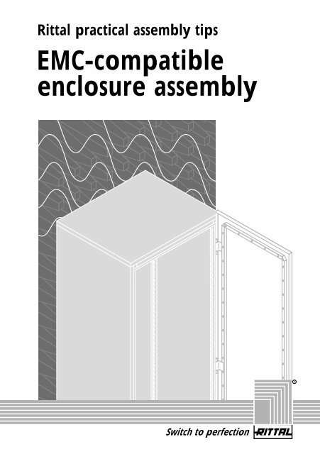
<strong>Rittal</strong> practical <strong>assembly</strong> tips<br />
<strong>EMC</strong>-<strong>compatible</strong><br />
<strong>enclosure</strong> <strong>assembly</strong><br />
Switch to perfection<br />
R
The <strong>Rittal</strong><br />
<strong>EMC</strong> concept<br />
The definition of electromagnetic<br />
compatibility (<strong>EMC</strong>) is<br />
the ability of an electrical<br />
device to function satisfactorily<br />
in its electromagnetic<br />
environment without adversely<br />
affecting this environment,<br />
which may include<br />
other equipment.<br />
On the basis of this, the<br />
essential requirements of<br />
<strong>EMC</strong> are: To prevent/reduce<br />
interference emission and<br />
to offer defined resistance<br />
against interference.<br />
<strong>EMC</strong> is an indispensable element<br />
of quality, and the protection<br />
requirements regulated<br />
by law, along with the<br />
technical risks, <strong>EMC</strong> must be<br />
taken into account at the<br />
planning stage when developing<br />
equipment.<br />
With the <strong>enclosure</strong>, as a<br />
housing for electrical/electronic<br />
controls and systems,<br />
the following points must be<br />
observed:<br />
2<br />
– These days, the intelligence<br />
contained inside<br />
<strong>enclosure</strong>s is becoming<br />
ever faster, i.e. shorter<br />
switching times and<br />
steeper pulse edges,<br />
leading to ever higher<br />
frequencies of voltages<br />
and currents.<br />
– Ever lower energy consumption,<br />
i.e. lower voltage/current<br />
levels,<br />
means that components<br />
are more readily influenced<br />
by interference.<br />
– The siting of controls<br />
in ever more confined<br />
spaces, i.e. smaller<br />
distances between<br />
components and cables,<br />
causing ever more frequent<br />
interference on<br />
different paths.<br />
– Technical progress will<br />
exacerbate these risks<br />
even further.<br />
A standard <strong>enclosure</strong> made<br />
of coated sheet steel can<br />
make a significant contribution<br />
towards the <strong>EMC</strong> of<br />
controls for machinery and<br />
systems, provided some<br />
simple population rules are<br />
taken into account.<br />
In applications with highfrequency<br />
field-bound<br />
interference, the use of an<br />
RF-shielded <strong>enclosure</strong> with<br />
a superior shielding effect<br />
may be required. The only<br />
way to draw definite conclusions<br />
about the type of<br />
<strong>enclosure</strong> which is necessary<br />
or adequate to comply<br />
with certain standard limits<br />
is by conducting measurements.<br />
This brochure is intended to<br />
provide recommendations<br />
for <strong>EMC</strong>-<strong>compatible</strong> <strong>enclosure</strong><br />
<strong>assembly</strong> and usage in<br />
machinery and systems for<br />
daily workshop practice.
This section contains valuable tips and<br />
information on comprehensive potential<br />
equalisation.<br />
This section contains practical suggestions<br />
for <strong>EMC</strong> measures within the<br />
<strong>enclosure</strong>.<br />
This section tells you the points you<br />
should take into account with cabling.<br />
Explanation of symbols<br />
The following symbols have been used in<br />
this manual for illustrative purposes.<br />
Effectiveness<br />
of the <strong>EMC</strong><br />
measures<br />
Immunity<br />
to interference<br />
Strip<br />
paint<br />
Comprehensive<br />
potential equalisation<br />
Measures within the <strong>enclosure</strong><br />
Cabling rules<br />
We have also assigned system accessories<br />
to the drawings, to make ordering easier.<br />
very good good poor<br />
very poor<br />
very<br />
sensitive sensitive<br />
Interference<br />
emission<br />
Paint surface<br />
with contact<br />
paint<br />
high low<br />
Paint<br />
SZ 2415.000<br />
3
Comprehensive<br />
potential equalisation<br />
4<br />
For <strong>EMC</strong> purposes, ideally there should be low and<br />
high-frequency potential equalisation between all metalic<br />
masses, <strong>enclosure</strong>s, machine and system components,<br />
which should be meshed as closely as possible.<br />
Enclosure for<br />
control and<br />
measurement<br />
technology<br />
Steel reinforcement<br />
in concrete<br />
ceilings, metallic bases<br />
in false ceilings<br />
Earth connections<br />
5m<br />
Enclosure for<br />
power distribution<br />
Duct for<br />
power cable<br />
Duct for<br />
low-power<br />
cable
Comprehensive<br />
potential equalisation<br />
Cable routing in<br />
machinery and equipment<br />
Basic principle: Avoid large cable loops; lay currentcarrying<br />
cables as close as possible to the reference<br />
potential.<br />
Enclosure 1<br />
Enclosure<br />
1 Power supply<br />
2 Data/control connection<br />
1<br />
Cable<br />
Earth connection<br />
Cable<br />
Reference potential<br />
1 2<br />
Measuring<br />
device<br />
Enclosure 2<br />
Machine<br />
Enclosure 1<br />
Enclosure<br />
1<br />
Cable<br />
Loop<br />
Reference potential<br />
1<br />
Measuring<br />
device<br />
Enclosure 2<br />
2<br />
Machine<br />
5
Comprehensive<br />
potential equalisation<br />
6<br />
Potential equalisation<br />
connections<br />
Potential<br />
equalisation<br />
rail<br />
Earthing<br />
straps<br />
SZ 2412.210 –<br />
SZ 2412.325<br />
L<br />
B<br />
Ideally:<br />
L<br />
< 3<br />
B<br />
In practice: Maximum<br />
possible cross section,<br />
large-area conductive<br />
mounting, low-inductive<br />
(therefore, a rectangle<br />
is better than a round<br />
conductor)<br />
Greenand-yellow<br />
PE conductor
Comprehensive<br />
potential equalisation<br />
Potential equalisation<br />
connections<br />
How to attach earthing straps<br />
Preparation<br />
of the contact points<br />
How to screw-fix metallic parts<br />
Contact cutter<br />
for frame section<br />
SZ 2414.000<br />
Plain washer<br />
and spring lock<br />
washer<br />
Screw connection<br />
Spring<br />
lock<br />
washer<br />
Screw connection<br />
Paint<br />
SZ 2415.000<br />
Contact cutter<br />
for earthing bolts<br />
SZ 2414.500<br />
Paint<br />
SZ 2415.000<br />
7
Comprehensive<br />
potential equalisation<br />
8<br />
Potential equalisation<br />
between <strong>enclosure</strong>s via a<br />
metallic cable duct<br />
Green-and-yellow<br />
conductor
Comprehensive<br />
potential equalisation<br />
How to connect<br />
metallic cable ducts<br />
to the <strong>enclosure</strong><br />
2 Paint<br />
SZ 2415.000<br />
1 Conductive connection<br />
2 Contact paint provides protection against corrosion<br />
1<br />
9
Comprehensive<br />
potential equalisation<br />
Conductive connection<br />
of metallic cable ducts<br />
10<br />
Paint<br />
SZ 2415.000<br />
Paint<br />
SZ 2415.000
Comprehensive<br />
potential equalisation<br />
Conductive connection<br />
of metallic cable ducts<br />
11
Comprehensive<br />
potential equalisation<br />
Conductive attachment<br />
of metallic cable ducts<br />
12
Comprehensive<br />
potential equalisation<br />
Conductive connection<br />
between machine<br />
and system components<br />
Welded earthing strap<br />
13
Measures<br />
within the <strong>enclosure</strong><br />
Functional <strong>enclosure</strong><br />
layout / spatial division<br />
14<br />
High outputs Low outputs<br />
Input Low outputs High outputs
Measures<br />
within the <strong>enclosure</strong><br />
Functional <strong>enclosure</strong> layout,<br />
division via internal partitions<br />
More powerful<br />
components<br />
Protect sensitive assemblies<br />
by means of encapsulation,<br />
shielded case/subrack within<br />
the <strong>enclosure</strong><br />
High outputs Low outputs<br />
Dividing area<br />
Mains Actuators Transducers, probes,<br />
detectors<br />
15
Measures<br />
within the <strong>enclosure</strong><br />
For optimum<br />
shielding effect:<br />
16<br />
Enclosure within an <strong>enclosure</strong><br />
Potential equalisation<br />
via suitable rails or<br />
conductive mounting plate<br />
Air-conditioning apertures<br />
with RF filters<br />
Mains filter/overvoltage<br />
protection at the point of entry,<br />
with large-area contact<br />
Conductive seal<br />
between the <strong>enclosure</strong> and<br />
removable <strong>enclosure</strong> panels<br />
Unshielded control cables<br />
via filter openings conductively<br />
connected to the <strong>enclosure</strong><br />
entry point<br />
Shielded viewing window,<br />
as small as possible<br />
Shielded cables via <strong>EMC</strong> PG<br />
screwed cable glands
Measures<br />
within the <strong>enclosure</strong><br />
Improve the shielding effect<br />
via optimum potential equalisation<br />
of the <strong>enclosure</strong> surfaces<br />
SZ 2412.210 –<br />
SZ 2412.325<br />
<strong>EMC</strong> earthing straps<br />
Earth straps<br />
SZ 2412.210 –<br />
SZ 2412.325<br />
17
Measures<br />
within the <strong>enclosure</strong><br />
The mounting plate as a potential equalisation<br />
surface: all components with a conductive<br />
housing can be conductively mounted with a<br />
large contact area.<br />
18<br />
Conductive mounting plate<br />
Long PE conductor<br />
Painted sheet metal
Measures<br />
within the <strong>enclosure</strong><br />
Cable shields should be contacted<br />
directly at the point of cable entry,<br />
where possible<br />
Ideally: All-round contact<br />
<strong>EMC</strong> cable glands<br />
SZ 2411.090 -<br />
SZ 2411.360<br />
<strong>EMC</strong> shield bus<br />
SZ 2413.375 and<br />
SZ 2367.060 - SZ 2367.120<br />
Soldered<br />
ring terminal<br />
<strong>EMC</strong> gland plates<br />
PS 4314.060 -<br />
PS 4314.080<br />
Potential equalisation<br />
on the mounting plate<br />
SZ 2367.060 -<br />
SZ 2367.120<br />
Tin-plated<br />
braiding<br />
19
Measures<br />
within the <strong>enclosure</strong><br />
Conductive arrangement of mains<br />
filters on gland plates or mounting plate,<br />
cable shield contacting on<br />
gland plates or mounting plate<br />
20<br />
Paint =<br />
insulation<br />
Important: Spatially separate input<br />
and output cables from one another;<br />
use as shielded cables<br />
Output:<br />
To actuator<br />
or to<br />
machine<br />
Power supply<br />
SZ 2367.060-<br />
SZ 2367.120<br />
CA<br />
Filter<br />
CA<br />
Output:<br />
To actuator or to machine<br />
Power supply<br />
CA<br />
Filter<br />
Power<br />
supply<br />
Output: To actuator<br />
or to machine<br />
Filter<br />
CA =<br />
control<br />
<strong>assembly</strong>
Measures<br />
within the <strong>enclosure</strong><br />
Position filters directly at<br />
the point of <strong>enclosure</strong> entry/exit,<br />
where possible<br />
Filter<br />
Power supply<br />
Important: Ensure there is<br />
large-area conductive connection<br />
between the filter housing and<br />
the mounting surface;<br />
avoid cable loops to the reference<br />
potential<br />
Paint =<br />
insulation<br />
Paint<br />
SZ 2415.000<br />
Filter<br />
Filter<br />
Power supply<br />
21
Measures<br />
within the <strong>enclosure</strong><br />
Position transformers on gland plates<br />
with large-area conduction,<br />
conductive connection of the shield<br />
22<br />
Metallic earth
Cabling rules<br />
Cable selection/routing<br />
Immunity to<br />
interference<br />
Interference<br />
emission<br />
Shielded,<br />
twisted<br />
cable pair<br />
Multi-wire cable<br />
Multi-wire cable,<br />
unshielded<br />
Multi-wire cable,<br />
shielded,<br />
in metal tube<br />
Unused conductor<br />
Shielded, twisted<br />
cable pair with<br />
extra shielding<br />
Unshielded,<br />
twisted cable pair<br />
Multi-wire cable,<br />
shielded<br />
or in metallic<br />
cable duct<br />
23
Cabling rules<br />
Cable routing between<br />
<strong>enclosure</strong>s and machine/system parts<br />
24<br />
Steel conduit<br />
Steel<br />
cable duct<br />
Cable trays<br />
or sheet<br />
steel supports<br />
Sheathings,<br />
open laying<br />
of bus cables<br />
etc.<br />
Surface<br />
cabling<br />
with cable<br />
clamps or<br />
other fixing<br />
components<br />
C cable tube,<br />
surfacemounted
Cabling rules<br />
Routing of cables in the cable duct<br />
Selection/population of cable ducts<br />
Solid<br />
metallic cable duct<br />
Open metallic cable duct Open mounting angle<br />
Areas with effective shielding<br />
against electromagnetic fields<br />
Plastic<br />
cable duct<br />
25
Cabling rules<br />
How to route cables with different<br />
interference emission and interference<br />
sensitivity in cable ducts<br />
26<br />
Unshielded cable<br />
Unshielded cable<br />
D as large as possible<br />
Unshielded cable<br />
D<br />
Unshielded cable<br />
Immunity to<br />
interference<br />
Very sensitive High<br />
Sensitive Low<br />
Interference<br />
emission
Cabling rules<br />
Shield contacting<br />
to potential equalisation<br />
Reference potential<br />
(machine chassis<br />
or separate rail)<br />
L ≈ 10 m<br />
L ≤ 10 m<br />
Cable shield with<br />
potential equalisation on one side<br />
Reference potential or<br />
potential equalisation rail<br />
with connection to chassis<br />
= lambda: wavelength<br />
of the maximum frequency<br />
occurring in the vicinity<br />
Cable shield without<br />
potential equalisation contact<br />
27
Cabling rules<br />
Cable routing<br />
28<br />
Connect unused conductor to reference potential<br />
90°<br />
Output<br />
90°<br />
Control<br />
Signals<br />
> 20 cm<br />
Use right-angled cable cross-overs wherever possible, and ensure adequate<br />
distance between interference-emitting and sensitive cables<br />
< 20 cm
Fix it by fax:<br />
Simply copy and complete this form, and fax it us!<br />
From:<br />
Surname First name<br />
Company Department<br />
Road<br />
Town/post code<br />
Telephone Fax<br />
Request for information:<br />
Please send me more information about:<br />
<strong>EMC</strong> subracks<br />
<strong>EMC</strong> instruments cases<br />
<strong>EMC</strong> wall-mounted <strong>enclosure</strong>s<br />
<strong>EMC</strong> <strong>enclosure</strong> systems<br />
<strong>EMC</strong> fan-and-filter units<br />
Please telephone me to arrange an appointment.<br />
My extension is:<br />
Please send me …… additional copies of this brochure.
Reliable protection against interference<br />
New! Ripac Microcomputer<br />
Packaging System:<br />
The complete subrack<br />
solution with the comprehensive<br />
<strong>EMC</strong> concept.<br />
Play it safe with the <strong>Rittal</strong> <strong>EMC</strong> range.<br />
Sophisticated standard products for <strong>EMC</strong>-<strong>compatible</strong><br />
packaging of electrics, electronics and data communications<br />
provide reliable protection against electromagnetic<br />
interference. <strong>Rittal</strong> <strong>EMC</strong> solutions are available as:<br />
• <strong>EMC</strong> subracks<br />
• <strong>EMC</strong> instrument cases<br />
• <strong>EMC</strong> wall mounted <strong>enclosure</strong>s<br />
• <strong>EMC</strong> <strong>enclosure</strong> systems<br />
• <strong>EMC</strong> fan-and filter units<br />
• and a wide range of <strong>EMC</strong> accessories.<br />
Switch to perfection<br />
R
<strong>Rittal</strong>-Werk � Rudolf Loh GmbH & Co. KG � P.O. Box 16 62 � D-35726 Herborn<br />
Telephone (0 27 72) 5 05-0 � Telefax (0 27 72) 5 05-23 19<br />
eMail: Info@rittal.de � Internet: http://www.rittal.com<br />
Switch to perfection<br />
R<br />
12/97


