Rittal – RiLine NH The new generation of isolators
Rittal – RiLine NH The new generation of isolators
Rittal – RiLine NH The new generation of isolators

You also want an ePaper? Increase the reach of your titles
YUMPU automatically turns print PDFs into web optimized ePapers that Google loves.
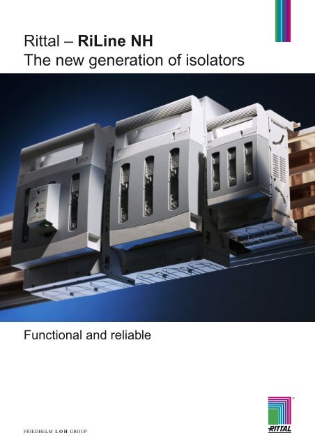
<strong>Rittal</strong> <strong>–</strong> <strong>RiLine</strong> <strong>NH</strong><br />
<strong>The</strong> <strong>new</strong> <strong>generation</strong> <strong>of</strong> <strong>isolators</strong><br />
Functional and reliable<br />
R
Easy to use,<br />
with added benefits<br />
Contents<br />
<strong>NH</strong> bus-mounting on-load isolator<br />
for <strong>Rittal</strong> <strong>RiLine</strong>60 busbar systems...................................6 <strong>–</strong> 9<br />
<strong>NH</strong> on-load <strong>isolators</strong><br />
for mounting plate assembly........................................10 <strong>–</strong> 13<br />
Accessories ........................................................................ 14<br />
Busbar adaptor .................................................................. 15<br />
Technical information ..................................................16 <strong>–</strong> 22<br />
List <strong>of</strong> model numbers/Index ............................................. 23<br />
One isolator for top or bottom entry<br />
In just a few seconds, you can swap the cable outlet from<br />
the top to the bottom using the same device: Simply rotate<br />
the mounting hook, and it's done!<br />
This function <strong>of</strong>fers a clear benefit for customers, because<br />
warehousing costs can be slashed by 50 %.<br />
2 <strong>Rittal</strong> <strong>RiLine</strong> <strong>NH</strong>
<strong>The</strong> continual advancement <strong>of</strong> the <strong>Rittal</strong> <strong>NH</strong> isolator family combines optimum functionality with outstanding looks. <strong>The</strong>se<br />
design properties support system-compatible integration into the <strong>RiLine</strong>60 contact hazard protection concept with<br />
base tray. <strong>Rittal</strong> has continued its strategy <strong>of</strong> maximising user benefits in the power distribution segment with the <strong>RiLine</strong> <strong>NH</strong>.<br />
Innovations with outstanding user benefits!<br />
Reliable contact<br />
<strong>The</strong> tried-and-trusted<br />
screw terminal system<br />
allows simple alignment<br />
<strong>of</strong> the <strong>NH</strong> units<br />
from the side, as well as<br />
reliable, low heat-loss<br />
contact on the busbars.<br />
<strong>Rittal</strong> <strong>RiLine</strong> <strong>NH</strong><br />
Connection systems to suit your<br />
requirements<br />
Customers can choose between<br />
user-friendly<br />
● Box terminals or<br />
● Screw terminals.<br />
All <strong>NH</strong> <strong>isolators</strong> with screw<br />
terminals may be retro-fitted<br />
with prism clamps.<br />
3
Added value with<br />
protective functions<br />
Ultra-reliable<br />
In two variants:<br />
Fuse monitoring, optionally available<br />
as an<br />
● electronic or<br />
● electromechanical version.<br />
This helps to increase plant<br />
availability and process reliability.<br />
Simply latch and seal<br />
Operational safety is further enhanced by the<br />
easy-to-use lid lock, which prevents unintentional<br />
opening <strong>of</strong> the isolator lid and is also<br />
sealable.<br />
Service-friendling monitoring<br />
Voltage test holes are automatically covered<br />
once testing is complete.<br />
Hands-on safety<br />
Comprehensive contact hazard<br />
protection and the ultimate in user<br />
comfort, thanks to an ergonomically<br />
designed isolator lid with a convenient<br />
actuator handle.<br />
4 <strong>Rittal</strong> <strong>RiLine</strong> <strong>NH</strong>
As everyone knows, it is <strong>of</strong>ten the “little things” which truly add value. For example, the <strong>new</strong> <strong>RiLine</strong> <strong>NH</strong> <strong>isolators</strong> <strong>of</strong>fer<br />
decisive assembly advantages in terms <strong>of</strong> time, cost, reliability and user-friendliness. Exceptional user benefits in a practical<br />
yet stylish design.<br />
Top-mounting means efficiency<br />
Space-saving configuration <strong>of</strong> all<br />
<strong>RiLine</strong> <strong>NH</strong> <strong>isolators</strong> because all<br />
<strong>RiLine</strong>60 busbar supports are suitable<br />
for top mounting <strong>–</strong> even the flat<br />
bar support! <strong>The</strong> super-slimline<br />
design <strong>of</strong>fers additional space<br />
efficiency.<br />
Clear labelling<br />
Visible, generously proportioned<br />
labelling space on all <strong>NH</strong> <strong>isolators</strong>.<br />
<strong>Rittal</strong> <strong>RiLine</strong> <strong>NH</strong><br />
Signals to the control centre<br />
Micro-switches indicate the switching position<br />
<strong>of</strong> the isolator lid to the control desk. Convenient<br />
routing <strong>of</strong> the control cables is another<br />
key feature.<br />
Outstanding design<br />
Assembly, installation, control and<br />
monitoring <strong>–</strong> each function has been<br />
carefully designed to <strong>of</strong>fer maximum<br />
user benefits. This combination<br />
<strong>of</strong> practicality and style is<br />
reflected in all model sizes.<br />
5
<strong>Rittal</strong> <strong>RiLine</strong> <strong>NH</strong><br />
<strong>NH</strong> bus-mounting on-load isolator, size 00<br />
1 2 3 106<br />
For direct mounting on <strong>RiLine</strong>60<br />
busbar systems (60 mm bar<br />
centre distance).<br />
Material:<br />
Chassis, lid, contact hazard<br />
protection: Polyamide PA6<br />
Contact tracks:<br />
Electrolytic copper, silver-plated<br />
Supply includes:<br />
Top and bottom covers.<br />
Technical information,<br />
see page 16 <strong>–</strong> 21.<br />
6 <strong>Rittal</strong> <strong>RiLine</strong> <strong>NH</strong><br />
194<br />
33 33<br />
104<br />
194<br />
106<br />
33 33<br />
1 2 3<br />
Size Packs <strong>of</strong> Size 00 Page<br />
Rated current 160 A<br />
Rated operating voltage 690 V~/500 V~ 1)<br />
Cable outlet top/bottom<br />
Type <strong>of</strong> connection Box terminal Screw M8<br />
Connection <strong>of</strong> round conductors 4 <strong>–</strong> 70 mm2 up to 95 mm2 Clamping area for laminated copper bars<br />
Tightening torque<br />
13 x 13 mm 20 x 5 mm<br />
● Assembly screw<br />
6 Nm<br />
6 Nm<br />
● Terminal screw<br />
4.5 Nm<br />
12 Nm<br />
For bar thickness 5/10 mm 5/10 mm<br />
Model No. SV 9343.000 9343.010<br />
with electronic fuse monitoring1) 1<br />
2<br />
Model No. SV<br />
1 9343.020 9343.030<br />
3<br />
with electromechanical fuse monitoring<br />
Model No. SV<br />
1 9343.040 9343.050<br />
Accessories<br />
Micro-switch 5 3071.000 3071.000 14<br />
Connection space cover 2 9344.520 9344.520 14<br />
Prism terminal 3 <strong>–</strong> 9344.600 14<br />
1) Rated operating voltage 500 V~ for <strong>NH</strong> <strong>isolators</strong> with electronic fuse monitoring.<br />
28<br />
104<br />
194<br />
106<br />
33 33<br />
104<br />
69
For mounting on <strong>RiLine</strong>60<br />
busbar systems (60 mm bar<br />
centre distance).<br />
Material:<br />
Chassis, lid, contact hazard<br />
protection: Polyamide PA6<br />
Contact tracks:<br />
Electrolytic copper, silver-plated<br />
<strong>Rittal</strong> <strong>RiLine</strong> <strong>NH</strong><br />
1 2 3<br />
Supply includes:<br />
Top and bottom covers.<br />
Technical information,<br />
see page 16 <strong>–</strong> 21.<br />
<strong>Rittal</strong> <strong>RiLine</strong> <strong>NH</strong><br />
<strong>NH</strong> bus-mounting on-load <strong>isolators</strong>, size 1<br />
298<br />
298<br />
184<br />
57 57<br />
184<br />
57 57<br />
69<br />
110<br />
1 2<br />
Size Packs <strong>of</strong> Size 1 Page<br />
Rated current 250 A<br />
Rated operating voltage 690 V~/500 V~ 1)<br />
Cable outlet top/bottom<br />
Type <strong>of</strong> connection Box terminal Screw M10<br />
Connection <strong>of</strong> round conductors 35 <strong>–</strong> 150 mm2 2) up to 150 mm2 Clamping area for laminated copper bars<br />
Tightening torque<br />
20 x 14 mm 32 x 10 mm<br />
● Assembly screw<br />
6 Nm<br />
6 Nm<br />
● Terminal screw<br />
12 Nm<br />
20 Nm<br />
For bar thickness 5/10 mm 5/10 mm<br />
Model No. SV 9343.100 9343.110<br />
with electronic fuse monitoring1) 1<br />
2<br />
Model No. SV<br />
1 9343.120 9343.130<br />
3<br />
with electromechanical fuse monitoring<br />
Model No. SV<br />
1 9343.140 9343.150<br />
Accessories<br />
Micro-switch 2 9344.510 9344.510 14<br />
Connection space cover 2 9344.530 9344.530 14<br />
Box terminal 3 <strong>–</strong> 9344.610 14<br />
Arcing chamber 3 9344.680 9344.680 14<br />
1) Rated operating voltage 500 V~ for <strong>NH</strong> <strong>isolators</strong> with electronic fuse monitoring.<br />
2) Connection <strong>of</strong> sector-shaped conductors 50 <strong>–</strong> 150 mm2 .<br />
3<br />
110<br />
298<br />
184<br />
57 57<br />
28<br />
110<br />
7
<strong>Rittal</strong> <strong>RiLine</strong> <strong>NH</strong><br />
<strong>NH</strong> bus-mounting on-load <strong>isolators</strong>, size 2<br />
For direct mounting on <strong>RiLine</strong>60<br />
busbar systems (60 mm bar<br />
centre distance).<br />
Material:<br />
Chassis, lid, contact hazard<br />
protection: Polyamide PA6<br />
Contact tracks:<br />
Electrolytic copper, silver-plated<br />
1 2 3<br />
Supply includes:<br />
Top and bottom covers.<br />
Technical information,<br />
see page 16 <strong>–</strong> 21.<br />
8 <strong>Rittal</strong> <strong>RiLine</strong> <strong>NH</strong><br />
298<br />
298<br />
210<br />
65 65<br />
210<br />
65 65<br />
69<br />
130<br />
1 2<br />
Size Packs <strong>of</strong> Size 2 Page<br />
Rated current 400 A<br />
Rated operating voltage 690 V~/500 V~ 1)<br />
Cable outlet top/bottom<br />
Type <strong>of</strong> connection Box terminal Screw M10<br />
Connection <strong>of</strong> round conductors 95 <strong>–</strong> 300 mm2 2) up to 240 mm2 Clamping area for laminated copper bars<br />
Tightening torque<br />
32 x 20 mm 50 x 10 mm<br />
● Assembly screw<br />
8 Nm<br />
8 Nm<br />
● Terminal screw<br />
20 Nm<br />
20 Nm<br />
For bar thickness 5/10 mm 5/10 mm<br />
Model No. SV 9343.200 9343.210<br />
with electronic fuse monitoring1) 1<br />
2<br />
Model No. SV<br />
1 9343.220 9343.230<br />
3<br />
with electromechanical fuse monitoring<br />
Model No. SV<br />
1 9343.240 9343.250<br />
Accessories<br />
Micro-switch 2 9344.510 9344.510 14<br />
Connection space cover 2 9344.540 9344.540 14<br />
Box terminal 3 <strong>–</strong> 9344.620 14<br />
Arcing chamber 3 9344.680 9344.680 14<br />
1) Rated operating voltage 500 V~ for <strong>NH</strong> <strong>isolators</strong> with electronic fuse monitoring.<br />
2) Connection <strong>of</strong> sector-shaped conductors 120 <strong>–</strong> 300 mm2 .<br />
3<br />
130<br />
298<br />
210<br />
65 65<br />
28<br />
130
For mounting on <strong>RiLine</strong>60<br />
busbar systems (60 mm bar<br />
centre distance).<br />
Material:<br />
Chassis, lid, contact hazard<br />
protection: Polyamide PA6<br />
Contact tracks:<br />
Electrolytic copper, silver-plated<br />
<strong>Rittal</strong> <strong>RiLine</strong> <strong>NH</strong><br />
1 2 3<br />
Supply includes:<br />
Top and bottom covers.<br />
Technical information,<br />
see page 16 <strong>–</strong> 21.<br />
<strong>Rittal</strong> <strong>RiLine</strong> <strong>NH</strong><br />
<strong>NH</strong> bus-mounting on-load isolator, size 3<br />
298<br />
298<br />
250<br />
80<br />
250<br />
80<br />
80<br />
80<br />
69<br />
130<br />
1 2<br />
Size Packs <strong>of</strong> Size 3 Page<br />
Rated current 630 A<br />
Rated operating voltage 690 V~/500 V~ 1)<br />
Cable outlet top/bottom<br />
Type <strong>of</strong> connection Box terminal Screw M10<br />
Connection <strong>of</strong> round conductors 95 <strong>–</strong> 300 mm2 2) up to 300 mm2 Clamping area for laminated copper bars<br />
Tightening torque<br />
32 x 20 mm 50 x 10 mm<br />
● Assembly screw<br />
8 Nm<br />
8 Nm<br />
● Terminal screw<br />
20 Nm<br />
20 Nm<br />
For bar thickness 5/10 mm 5/10 mm<br />
Model No. SV 9343.300 9343.310<br />
with electronic fuse monitoring1) 1<br />
2<br />
Model No. SV<br />
1 9343.320 9343.330<br />
3<br />
with electromechanical fuse monitoring<br />
Model No. SV<br />
1 9343.340 9343.350<br />
Accessories<br />
Micro-switch 2 9344.510 9344.510 14<br />
Connection space cover 2 9344.550 9344.550 14<br />
Box terminal 3 <strong>–</strong> 9344.620 14<br />
Arcing chamber 3 9344.680 9344.680 14<br />
1) Rated operating voltage 500 V~ for <strong>NH</strong> <strong>isolators</strong> with electronic fuse monitoring.<br />
2) Connection <strong>of</strong> sector-shaped conductors 120 <strong>–</strong> 300 mm2 .<br />
3<br />
130<br />
298<br />
250<br />
80<br />
80<br />
28<br />
130<br />
9
<strong>Rittal</strong> <strong>RiLine</strong> <strong>NH</strong><br />
<strong>NH</strong> on-load <strong>isolators</strong> size 00<br />
1 2 3 106<br />
For mounting plate assembly.<br />
Material:<br />
Chassis, lid, contact hazard<br />
protection: Polyamide PA6<br />
Contact tracks:<br />
Electrolytic copper, silver-plated<br />
Technical information,<br />
see page 16 <strong>–</strong> 21.<br />
Hole sizes,<br />
see page 22.<br />
10 <strong>Rittal</strong> <strong>RiLine</strong> <strong>NH</strong><br />
194<br />
33 33<br />
80<br />
194<br />
106<br />
33 33<br />
1 2 3<br />
Size Packs <strong>of</strong> Size 00 Page<br />
Rated current 160 A<br />
Rated operating voltage 690 V~/500 V~ 1)<br />
Cable outlet top/bottom<br />
Type <strong>of</strong> connection Box terminal Screw M8<br />
Connection <strong>of</strong> round conductors 4 <strong>–</strong> 70 mm2 up to 95 mm2 Clamping area for laminated copper bars 13 x 13 mm 20 x 5 mm<br />
Tightening torque<br />
Terminal screw<br />
4.5 Nm 12 Nm<br />
Model No. SV 9344.000 9344.010<br />
with electronic fuse monitoring1) 1<br />
2<br />
Model No. SV<br />
1 9344.020 9344.030<br />
3<br />
with electromechanical fuse monitoring<br />
Model No. SV<br />
1 9344.040 9344.050<br />
Accessories<br />
Micro-switch 5 3071.000 3071.000 14<br />
Connection space cover 2 9344.520 9344.520 14<br />
Prism terminal 3 <strong>–</strong> 9344.600 14<br />
1) Rated operating voltage 500 V~ for <strong>NH</strong> <strong>isolators</strong> with electronic fuse monitoring.<br />
28<br />
80<br />
194<br />
106<br />
33 33<br />
69<br />
80
<strong>Rittal</strong> <strong>RiLine</strong> <strong>NH</strong><br />
1 2 3<br />
For mounting plate assembly.<br />
Material:<br />
Chassis, lid, contact hazard<br />
protection: Polyamide PA6<br />
Contact tracks:<br />
Electrolytic copper, silver-plated<br />
Technical information,<br />
see page 16 <strong>–</strong> 21.<br />
Hole sizes,<br />
see page 22.<br />
298<br />
298<br />
184<br />
57 57<br />
184<br />
57 57<br />
69<br />
110<br />
1 2<br />
3<br />
110<br />
<strong>Rittal</strong> <strong>RiLine</strong> <strong>NH</strong><br />
<strong>NH</strong> on-load isolator, size 1<br />
Size Packs <strong>of</strong> Size 1 Page<br />
Rated current 250 A<br />
Rated operating voltage 690 V~/500 V~ 1)<br />
Cable outlet top/bottom<br />
Type <strong>of</strong> connection Box terminal Screw M10<br />
Connection <strong>of</strong> round conductors 35 <strong>–</strong> 150 mm2 2) up to 150 mm2 Clamping area for laminated copper bars 20 x 14 mm 32 x 10 mm<br />
Tightening torque<br />
Terminal screw<br />
12 Nm 20 Nm<br />
Model No. SV 9344.100 9344.110<br />
with electronic fuse monitoring1) 1<br />
2<br />
Model No. SV<br />
1 9344.120 9344.130<br />
3<br />
with electromechanical fuse monitoring<br />
Model No. SV<br />
1 9344.140 9344.150<br />
Accessories<br />
Micro-switch 2 9344.510 9344.510 14<br />
Connection space cover 2 9344.530 9344.530 14<br />
Box terminal 3 <strong>–</strong> 9344.610 14<br />
Arcing chamber 3 9344.680 9344.680 14<br />
1) Rated operating voltage 500 V~ for <strong>NH</strong> <strong>isolators</strong> with electronic fuse monitoring.<br />
2) Connection <strong>of</strong> sector-shaped conductors 50 <strong>–</strong> 150 mm2 .<br />
298<br />
184<br />
57 57<br />
28<br />
110<br />
11
<strong>Rittal</strong> <strong>RiLine</strong> <strong>NH</strong><br />
<strong>NH</strong> on-load isolator size 2<br />
1 2 3<br />
For mounting plate assembly.<br />
Material:<br />
Chassis, lid, contact hazard<br />
protection: Polyamide PA6<br />
Contact tracks:<br />
Electrolytic copper, silver-plated<br />
Technical information,<br />
see page 16 <strong>–</strong> 21.<br />
Hole sizes,<br />
see page 22.<br />
12 <strong>Rittal</strong> <strong>RiLine</strong> <strong>NH</strong><br />
298<br />
298<br />
210<br />
65 65<br />
210<br />
65 65<br />
69<br />
130<br />
1 2<br />
Size Packs <strong>of</strong> Size 2 Page<br />
Rated current 400 A<br />
Rated operating voltage 690 V~/500 V~ 1)<br />
Cable outlet top/bottom<br />
Type <strong>of</strong> connection Box terminal Screw M10<br />
Connection <strong>of</strong> round conductors 95 <strong>–</strong> 300 mm2 2) up to 240 mm2 Clamping area for laminated copper bars 32 x 20 mm 50 x 10 mm<br />
Tightening torque<br />
Terminal screw<br />
20 Nm 20 Nm<br />
Model No. SV 9344.200 9344.210<br />
with electronic fuse monitoring1) 1<br />
2<br />
Model No. SV<br />
1 9344.220 9344.230<br />
3<br />
with electromechanical fuse monitoring<br />
Model No. SV<br />
1 9344.240 9344.250<br />
Accessories<br />
Micro-switch 2 9344.510 9344.510 14<br />
Connection space cover 2 9344.540 9344.540 14<br />
Box terminal 3 <strong>–</strong> 9344.620 14<br />
Arcing chamber 3 9344.680 9344.680 14<br />
1) Rated operating voltage 500 V~ for <strong>NH</strong> <strong>isolators</strong> with electronic fuse monitoring.<br />
2) Connection <strong>of</strong> sector-shaped conductors 120 <strong>–</strong> 300 mm2 .<br />
3<br />
130<br />
298<br />
210<br />
65 65<br />
28<br />
130
<strong>Rittal</strong> <strong>RiLine</strong> <strong>NH</strong><br />
1 2 3<br />
For mounting plate assembly.<br />
Material:<br />
Chassis, lid, contact hazard<br />
protection: Polyamide PA6<br />
Contact tracks:<br />
Electrolytic copper, silver-plated<br />
Technical information,<br />
see page 16 <strong>–</strong> 21.<br />
Hole sizes,<br />
see page 22.<br />
298<br />
298<br />
250<br />
80<br />
250<br />
80<br />
80<br />
80<br />
69<br />
130<br />
1 2<br />
3<br />
130<br />
<strong>Rittal</strong> <strong>RiLine</strong> <strong>NH</strong><br />
<strong>NH</strong> on-load isolator, size 3<br />
Size Packs <strong>of</strong> Size 3 Page<br />
Rated current 630 A<br />
Rated operating voltage 690 V~/500 V~ 1)<br />
Cable outlet top/bottom<br />
Type <strong>of</strong> connection Box terminal Screw M10<br />
Connection <strong>of</strong> round conductors 95 <strong>–</strong> 300 mm2 2) up to 300 mm2 Clamping area for laminated copper bars 32 x 20 mm 50 x 10 mm<br />
Tightening torque<br />
Terminal screw<br />
20 Nm 20 Nm<br />
Model No. SV 9344.300 9344.310<br />
with electronic fuse monitoring1) 1<br />
2<br />
Model No. SV<br />
1 9344.320 9344.330<br />
3<br />
with electromechanical fuse monitoring<br />
Model No. SV<br />
1 9344.340 9344.350<br />
Accessories<br />
Micro-switch 2 9344.510 9344.510 14<br />
Connection space cover 2 9344.550 9344.550 14<br />
Box terminal 3 <strong>–</strong> 9344.620 14<br />
Arcing chamber 3 9344.680 9344.680 14<br />
1) Rated operating voltage 500 V~ for <strong>NH</strong> <strong>isolators</strong> with electronic fuse monitoring.<br />
2) Connection <strong>of</strong> sector-shaped conductors 120 <strong>–</strong> 300 mm2 .<br />
298<br />
250<br />
80<br />
80<br />
28<br />
130<br />
13
<strong>Rittal</strong> <strong>RiLine</strong> <strong>NH</strong><br />
Accessories for <strong>NH</strong> <strong>isolators</strong>, size 00 to 3<br />
1<br />
2<br />
1<br />
2<br />
Micro-switch<br />
To indicate the position <strong>of</strong> the <strong>NH</strong> cover.<br />
Connection space cover<br />
● For extending the contact hazard protection<br />
cover plate, e.g. when using ring terminals with<br />
a long collar.<br />
● Bayable as required at the top and bottom.<br />
Material:<br />
Polyamide PA6<br />
B = Width<br />
T = Depth<br />
T<br />
Prism terminals/<br />
box terminals<br />
for <strong>NH</strong> <strong>isolators</strong>, sizes 00 to 3<br />
with screw terminal<br />
For direct connection <strong>of</strong> round and sector-shaped<br />
conductors.<br />
Design<br />
B<br />
For<br />
<strong>NH</strong> <strong>isolators</strong><br />
Packs <strong>of</strong> Model No. SV<br />
Size 00 5 3071.000<br />
Size 1 <strong>–</strong> 3 2 9344.5101) 1) Including plastic lug for attaching the<br />
microswitch to the isolator chassis.<br />
14 <strong>Rittal</strong> <strong>RiLine</strong> <strong>NH</strong><br />
H<br />
For<br />
<strong>NH</strong> <strong>isolators</strong><br />
Round<br />
conductors<br />
1<br />
2<br />
For<br />
<strong>NH</strong> <strong>isolators</strong><br />
Packs <strong>of</strong> Model No. SV<br />
Size 00 2 9344.520<br />
Size 1 2 9344.530<br />
Size 2 2 9344.540<br />
Size 3 2 9344.550<br />
Model No. SV<br />
Connection<br />
B<br />
mm<br />
H<br />
mm<br />
T<br />
mm<br />
9344.520 106 46 37<br />
9344.530 184 70 42<br />
9344.540 210 70 42<br />
9344.550 250 70 42<br />
Sector-shaped<br />
conductors<br />
Tightening<br />
torque<br />
Packs<br />
<strong>of</strong><br />
Model No. SV<br />
Prism terminals Size 00 10 <strong>–</strong> 70 mm2 10 <strong>–</strong> 70 mm2 1<br />
3 Nm 3 9344.600<br />
2 Box terminals<br />
Arc chambers<br />
for <strong>NH</strong> <strong>isolators</strong>, sizes 1 to 3<br />
To increase switching capacity.<br />
Technical specifications:<br />
See table “<strong>NH</strong> <strong>isolators</strong><br />
(utilisation category)”,<br />
page 16.<br />
Size 1 35 <strong>–</strong> 150 mm2 50 <strong>–</strong> 150 mm2 20 Nm 3 9344.610<br />
Size 2/3 95 <strong>–</strong> 300 mm2 120 <strong>–</strong> 300 mm2 20 Nm 3 9344.620<br />
Packs <strong>of</strong> Model No. SV<br />
3 9344.680
<strong>Rittal</strong> <strong>RiLine</strong> <strong>NH</strong><br />
<strong>Rittal</strong> <strong>RiLine</strong> <strong>NH</strong><br />
Busbar adaptor/<strong>NH</strong> fused isolator, size 00 (100 mm)<br />
Busbar adaptor<br />
for <strong>NH</strong> on-load <strong>isolators</strong><br />
For mounting <strong>NH</strong> <strong>isolators</strong> for mounting plate<br />
assembly (see page 11 <strong>–</strong> 13) on 100 mm busbar<br />
systems.<br />
Outlet top/bottom.<br />
Technical information<br />
For assembly instructions, see page 22.<br />
<strong>NH</strong> fused isolator, size 00<br />
For direct mounting on 100 mm busbar systems,<br />
no drilling required.<br />
Note:<br />
For further information and technical<br />
specifications,<br />
see Catalogue 31, pages 349, 1134.<br />
For<br />
<strong>NH</strong> <strong>isolators</strong><br />
Size 1<br />
(SV 9344.1XX)<br />
Size 2<br />
(SV 9344.2XX)<br />
Size 3<br />
(SV 9344.3XX)<br />
Packs <strong>of</strong> Model No. SV<br />
1 9344.810<br />
1 9344.820<br />
1 9344.830<br />
Size 00<br />
Rated current 160 A<br />
Rated operating voltage 690 V~<br />
Cable outlet top/bottom<br />
Type <strong>of</strong> connection<br />
Tightening torque<br />
Screw M8<br />
● Assembly screw<br />
6 Nm<br />
● Terminal screw<br />
14 Nm<br />
Packs <strong>of</strong> 1<br />
Model No. SV 3591.010<br />
15
<strong>Rittal</strong> <strong>RiLine</strong> <strong>NH</strong><br />
Technical information<br />
<strong>NH</strong> isolator, sizes 00 to 3<br />
Technical specifications<br />
IEC 60 947-3<br />
Size<br />
(<strong>NH</strong> fuse inserts to VDE 0636-201)<br />
Size 00 Size 1 Size 2 Size 3<br />
Rated operating current Ie 160 A 250 A 400 A 630 A<br />
Rated operating voltage Ue 690 V AC1) 690 V AC1) 690 V AC1) 690 V AC1) Rated insulation voltage Ui 1000 V 1000 V 1000 V 1000 V<br />
Rated surge voltage resistance Uimp 8 kV1) 8 kV1) 8 kV1) 8 kV1) Rated frequency 50/60 Hz 50/60 Hz 50/60 Hz 50/60 Hz<br />
Conditional rated short-circuit current<br />
at 690 V AC 80 kA 80 kA 50 kA 80 kA<br />
(when protected with fuses)<br />
at 500 V AC 80 kA 80 kA 80 kA 80 kA<br />
400 V AC AC-23B AC-23B (AC-23B<br />
Utilisation category<br />
2) ) AC-23B (AC-23B2) ) AC-23B (AC-23B2) )<br />
500 V AC AC-22B AC-23B (AC-23B2) ) AC-22B (AC-23B2) ) AC-22B (AC-23B2) )<br />
690 V AC AC-21B AC-22B (AC-23B2) ) AC-21B (AC-23B2) ) AC-21B (AC-23B2) )<br />
220 V DC3) DC-22B2) DC-21B (DC-22B2) ) DC-21B (DC-22B2) ) DC-21B (DC-22B2) )<br />
440 V DC3) <strong>–</strong> DC-22B2) DC-22B2) DC-22B2) Mechanical life (switching cycles) 1400 1400 800 800<br />
Electrical life (switching cycles) 200 200 200 200<br />
Permissible ambient temperature <strong>–</strong>20°C to +60°C <strong>–</strong>20°C to +60°C <strong>–</strong>20°C to +60°C <strong>–</strong>20°C to +60°C<br />
Pv max./ fuse insert 12 W 23 W 34 W 48 W<br />
1) When using <strong>NH</strong> <strong>isolators</strong> with electronic or electromechanical fuse monitoring, the rating data in the following table will apply.<br />
2) With arcing chambers (Model No. SV 9344.680) for increased switching capacity.<br />
3) DC application with population <strong>of</strong> phase L1 and L3.<br />
Electronic and electromechanical fuse monitoring<br />
Technical specifications<br />
Rated operating voltage Ue<br />
Electronic<br />
fuse monitoring<br />
AC 400 V to AC 500 V (50/60 Hz)<br />
Electromechanical<br />
fuse monitoring<br />
AC 24 V to AC 690 V (50/60 Hz)<br />
DC 24 V to DC 250 V<br />
Rated surge voltage resistance Uimp 3.5 kV 6 kV<br />
Response time < 0.5 s < 2 s<br />
Auxiliary contacts 1 NO, 1 NC 1 NO, 1 NC<br />
Load capacity <strong>of</strong> auxiliary contacts 5 A 4 A<br />
Permissible ambient temperature <strong>–</strong>20°C to +60°C <strong>–</strong>20°C to +60°C<br />
Display<br />
LED constantly green (operational)<br />
13/14: open<br />
11/12: closed<br />
LED flashing red (error message)<br />
13/14: closed<br />
11/12: open<br />
Rocker switch position “1” (operational)<br />
13/14: closed<br />
21/22: open<br />
Rocker switch position “0” (error message)<br />
13/14: open<br />
21/22: closed<br />
Connection <strong>of</strong> auxiliary contacts Terminal up to 1.5 mm2 Terminal up to 1.5 mm2 <strong>NH</strong> fuse inserts With contacted, live puller lugs<br />
Wiring diagram<br />
Function<br />
block<br />
LED LED<br />
13<br />
11<br />
12<br />
14<br />
L1 L2 L3<br />
22 21 13 14<br />
1 L1 3 L2 5 L3 22 13<br />
21 14<br />
2 T1 4 T2 6 T3<br />
Electronic fuse monitoring Electromechanical fuse monitoring<br />
16 <strong>Rittal</strong> <strong>RiLine</strong> <strong>NH</strong>
Simple busbar assembly<br />
For all sizes <strong>of</strong> <strong>RiLine</strong> <strong>NH</strong> bus-mounting onload<br />
<strong>isolators</strong>, the inner contact hazard protection<br />
cover plates are easily removed with<br />
just one release unit for device installation.<br />
Easy changeover <strong>of</strong> the cable outlet<br />
<strong>The</strong> uniform design <strong>of</strong> the <strong>RiLine</strong> <strong>NH</strong> <strong>generation</strong><br />
<strong>of</strong> <strong>isolators</strong> combines optimum functionality<br />
with an attractive design. This feature<br />
supports system-compatible integration into<br />
the <strong>RiLine</strong>60 contact hazard protection<br />
concept with base tray.<br />
<strong>Rittal</strong> <strong>RiLine</strong> <strong>NH</strong><br />
<strong>The</strong>re is one uniform tool size for mounting<br />
the <strong>NH</strong> units on the busbar system. All the<br />
required torque information is shown directly<br />
on the unit chassis.<br />
In just 3 seconds, the same device may be<br />
used to swap the cable outlet from top to<br />
bottom for all <strong>RiLine</strong> <strong>NH</strong> bus-mounting<br />
on-load <strong>isolators</strong> by simply rotating the<br />
mounting hook.<br />
<strong>Rittal</strong> <strong>RiLine</strong> <strong>NH</strong><br />
Technical information<br />
In this way, there is no need to decide<br />
whether the cable outlet will go at the top or<br />
bottom until immediately prior to assembly.<br />
This function <strong>of</strong>fers a clear benefit for<br />
customers, by halving the required<br />
warehousing and associated costs.<br />
Cable outlet at the bottom Rotating the mounting hook Cable outlet at the top<br />
17
<strong>Rittal</strong> <strong>RiLine</strong> <strong>NH</strong><br />
Technical information<br />
Tried-and-tested clamping screw system for contact<br />
<strong>The</strong> tried-and-trusted clamping screw system,<br />
as well as providing low-loss contact,<br />
is also much easier to assemble and dismantle<br />
than the snap-mounting system,<br />
particularly in the higher current range. Prior<br />
to attachment, the <strong>NH</strong> <strong>isolators</strong> are easily<br />
aligned at the sides.<br />
User-friendly box terminal for all sizes as standard<br />
In addition to the current market standard<br />
connection using screws or bolts, the <strong>new</strong><br />
<strong>Rittal</strong> <strong>RiLine</strong> <strong>NH</strong> isolator range alternatively<br />
<strong>of</strong>fers all sizes as standard with a userfriendly<br />
box terminal for inexpensive, timesaving<br />
connection <strong>of</strong> round and sectorshaped<br />
conductors. This saves the expensive<br />
labour costs for preparing the wire ends<br />
as well as the material costs <strong>of</strong> ring terminals.<br />
Lid lock and seal<br />
All designs have a screwdriver-operated<br />
lock as standard, to prevent unintentional<br />
opening <strong>of</strong> the isolator lid. In addition, the<br />
lock position may also be sealed with sealing<br />
wire.<br />
Lid lock Lid seal<br />
Service-friendly sliding windows<br />
with reclosable voltage testing holes<br />
<strong>The</strong> sliding windows integrated into the isolator<br />
lid have a special spring mechanism<br />
which automatically closes the holes after<br />
voltage testing.<br />
All <strong>RiLine</strong> <strong>NH</strong> <strong>isolators</strong> with screw connection<br />
may optionally be retro-fitted with box or<br />
prism terminals. Here too, all torques are<br />
directly visible either on the unit itself or on<br />
the terminals. All <strong>RiLine</strong> <strong>NH</strong> <strong>isolators</strong> size 1<br />
or above and all box and prism terminals<br />
from the accessory range still support the<br />
connection <strong>of</strong> round and sector-shape conductors<br />
made from Cu or Al (aluminium conductor<br />
connections must be checked at regular<br />
intervals).<br />
Safe voltage testing with a meter is also<br />
possible on the input side at the puller lug.<br />
Conductor<br />
version<br />
18 <strong>Rittal</strong> <strong>RiLine</strong> <strong>NH</strong><br />
Code<br />
Standard<br />
designation<br />
Single-wire e sol (solid)<br />
Multi-wire m s (stranded)<br />
Round<br />
Single-wire<br />
re sol<br />
Round<br />
Multi-wire<br />
rm s<br />
Sector<br />
Single-wire<br />
enclosures sol<br />
Sector<br />
Multi-wire<br />
sm s<br />
Fine-wire f f (flexible)
<strong>NH</strong> isolator with fuse monitoring<br />
As an alternative to the isolator version without<br />
fuse monitoring, all sizes are also optionally<br />
available with electronic fuse monitoring<br />
and electromechanical fuse monitoring. Both<br />
versions serve to increase plant availability<br />
and process reliability. Thanks to the floating<br />
contacts, the current device status may<br />
be readily forwarded to a superordinate<br />
control system. Outgoing signal tracks are<br />
conveniently connected using connectors.<br />
<strong>Rittal</strong> <strong>RiLine</strong> <strong>NH</strong><br />
<strong>The</strong> fuses used MUST be designed with live<br />
puller lugs, otherwise no alerts will be given<br />
by the electromechanical fuse monitoring in<br />
the event <strong>of</strong> a malfunction. By contrast, electronic<br />
fuse monitoring will emit a continuous<br />
error message in such cases.<br />
Technical specifications:<br />
See page 16.<br />
<strong>NH</strong> isolator with electronic fuse monitoring <strong>NH</strong> isolator with electromechanical fuse<br />
monitoring<br />
Electronic fuse monitoring<br />
Electronic fuse monitoring has a test button<br />
for easy simulation <strong>of</strong> a defective fuse during<br />
commissioning. <strong>The</strong> auxiliary power for<br />
the electronics is generated from the input<br />
side <strong>of</strong> the three-phase network. For technical<br />
reasons, the rated frequency <strong>of</strong> the supplying<br />
network (see technical specifications<br />
on page 16) must not be exceeded, otherwise<br />
the electronic fuse monitor will be<br />
damaged.<br />
Electromechanical fuse monitoring<br />
<strong>The</strong> isolator lids may be removed by simply<br />
loosening the connection. Unlike electronic<br />
monitoring, this system operates without<br />
auxiliary power, yet still performs the same<br />
functions. <strong>The</strong> rocker switch on the operating<br />
housing additionally provides a visual<br />
display <strong>of</strong> the operating status.<br />
Use in conjunction with motors in frequency<br />
converter mode is one such example. In<br />
such cases, electronic fuse monitoring must<br />
only be used as rotary current fusing for the<br />
frequency converter on the input side, and<br />
not in the frequency-modulated motor supply<br />
leads.<br />
A green and a red LED display indicate<br />
the operating status <strong>of</strong> the electronic fuse<br />
monitor.<br />
<strong>Rittal</strong> <strong>RiLine</strong> <strong>NH</strong><br />
Technical information<br />
Details <strong>of</strong> how to evaluate the LEDs and the<br />
floating alarm contacts may be found in the<br />
technical specifications. In the event <strong>of</strong> a<br />
mains failure or if the isolator lid is opened,<br />
the current operating status <strong>of</strong> the alarm<br />
contacts is retained.<br />
Note:<br />
In order to ensure fault-free operation,<br />
all fuses must be properly installed in<br />
accordance with the above conditions,<br />
since all the required measuring signals<br />
are measured from the puller lugs.<br />
19
<strong>Rittal</strong> <strong>RiLine</strong> <strong>NH</strong><br />
Technical information<br />
Simple signalling <strong>of</strong> the switching position with micro-switches<br />
All sizes have the option <strong>of</strong> accommodating<br />
micro-switches to indicate the switching<br />
position. <strong>The</strong> micro-switch simply clips into<br />
the relevant position in the isolator chassis.<br />
Two microswitch locators are available as<br />
standard for each device. This allows the<br />
switching position <strong>of</strong> the isolator lid to be<br />
communicated to a PLC, while using the<br />
second micro-switch to operate the load<br />
contactor at the same time. <strong>The</strong> microswitch<br />
wiring is routed through the device to the<br />
rear or through the pre-punched knock-out<br />
<strong>of</strong> the contact hazard protection cover<br />
plates.<br />
Size 00 Sizes 1 to 3 Cable gland<br />
Optimum labelling options<br />
Readily accessible and highly visible, the<br />
<strong>new</strong> <strong>generation</strong> <strong>of</strong> <strong>isolators</strong> <strong>of</strong>fers the option<br />
<strong>of</strong> labelling the units individually according<br />
to the wiring plan designation. <strong>The</strong> inter-<br />
changeable label is protected from dirt by a<br />
transparent film.<br />
Arc chambers to increase switching capacity<br />
for <strong>NH</strong> <strong>isolators</strong>, size 1 <strong>–</strong> 3<br />
Technical specifications:<br />
See table “<strong>NH</strong> <strong>isolators</strong><br />
(utilisation category)”, page 16.<br />
1. Removing the plastic bar 2. Clipping the arc chambers into position<br />
20 <strong>Rittal</strong> <strong>RiLine</strong> <strong>NH</strong>
Compact dimensions and ergonomic design<br />
● Same frame size from 00 to <strong>NH</strong>3.<br />
● Ergonomic isolator lid with user-friendly<br />
actuator handle, even for size 00 with an<br />
overall width <strong>of</strong> just 106 mm.<br />
Comprehensive contact hazard protection<br />
Comprehensive contact hazard protection<br />
ensures the highest standards <strong>of</strong> safety,<br />
coupled with superior user-friendliness.<br />
● Safe switching with integral hand<br />
protection.<br />
● Optional plug-in connection space covers<br />
(see accessories) to enlarge the<br />
connection space e.g. when using ring<br />
terminals with a long press sleeve.<br />
● Versatile cut-out options in the cable entry<br />
area.<br />
<strong>Rittal</strong> <strong>RiLine</strong> <strong>NH</strong><br />
● All versions <strong>of</strong>fer 3 defined positions for:<br />
1. Lid open (removal position)<br />
2. Lid switch-ready<br />
3. Lid closed<br />
● Perfect all-round protection in conjunction<br />
with the <strong>Rittal</strong> <strong>RiLine</strong>60 base tray.<br />
Top-mounting <strong>of</strong> supports even with flat bars<br />
<strong>The</strong> panels (removable at the side) allow<br />
top-mounting <strong>of</strong> <strong>Rittal</strong> <strong>RiLine</strong>60 busbar supports<br />
for all flat bars, enabling very compact<br />
configuration <strong>of</strong> the units. In conjunction with<br />
the super-slimline design, this allows a<br />
space-saving configuration.<br />
<strong>Rittal</strong> <strong>RiLine</strong> <strong>NH</strong><br />
Technical information<br />
Design<br />
Front<br />
with lid closed<br />
Front<br />
with lid open<br />
IP protection<br />
category<br />
IP 20<br />
IP 10<br />
21
<strong>Rittal</strong> <strong>RiLine</strong> <strong>NH</strong><br />
Technical information<br />
<strong>NH</strong> on-load isolator<br />
Page 10 <strong>–</strong> 13<br />
Hole size<br />
Size 00 (SV 9344.000 <strong>–</strong> 9344.050) Size 1 (SV 9344.100 <strong>–</strong> 9344.150)<br />
Size 2 (SV 9344.200 <strong>–</strong> 9344.250)<br />
Size 3 (SV 9344.300 <strong>–</strong> 9344.350)<br />
25<br />
12.5<br />
ø7<br />
66<br />
40<br />
75<br />
13<br />
97<br />
Busbar adaptor 100 mm<br />
for <strong>NH</strong> on-load isolator sizes 1 to 3, for mounting plate assembly<br />
Page 15<br />
100<br />
100<br />
Gr. A<br />
1 57 mm<br />
2 65 mm<br />
3 80 mm<br />
A A<br />
3<br />
4<br />
1<br />
164<br />
ø 5,5<br />
25<br />
25<br />
5<br />
ø11<br />
6<br />
A<br />
17 20 Nm<br />
19 30 Nm<br />
2,5 Nm TX 25<br />
Size A<br />
1 150<br />
2 166<br />
3 195<br />
Assembly instructions Note:<br />
For mounting <strong>NH</strong> on-load <strong>isolators</strong> size 1 to 3<br />
17/19<br />
(see page 11 <strong>–</strong> 13) on busbar systems with<br />
100 mm bar centre distance, an additional<br />
TX 25<br />
mounting hole (d = 5.5 mm) must be drilled in<br />
the respective isolator chassis as shown in the<br />
assembly instructions, stage 1 opposite. <strong>The</strong><br />
busbar adaptor is then mounted on the busbar<br />
using M10 screws, see stages 2 and 3, and the<br />
isolator is secured onto the adaptor as shown in<br />
2 M10<br />
stages 4 to 6.<br />
4<br />
22 <strong>Rittal</strong> <strong>RiLine</strong> <strong>NH</strong>
Model No. Page<br />
3071.000 14<br />
3591.010 15<br />
9343.000 6<br />
9343.010 6<br />
9343.020 6<br />
9343.030 6<br />
9343.040 6<br />
9343.050 6<br />
9343.100 7<br />
9343.110 7<br />
9343.120 7<br />
9343.130 7<br />
9343.140 7<br />
9343.150 7<br />
A<br />
<strong>Rittal</strong> <strong>RiLine</strong> <strong>NH</strong><br />
Model No. Page<br />
9343.200 8<br />
9343.210 8<br />
9343.220 8<br />
9343.230 8<br />
9343.240 8<br />
9343.250 8<br />
9343.300 9<br />
9343.310 9<br />
9343.320 9<br />
9343.330 9<br />
9343.340 9<br />
9343.350 9<br />
9344.000 10<br />
9344.010 10<br />
Adaptor 100 mm<br />
<strong>–</strong> for <strong>NH</strong> on-load isolator, size 1 <strong>–</strong> 3 15<br />
Arc chambers 14<br />
B<br />
Box terminals 14<br />
Busbar adaptor 100 mm<br />
<strong>–</strong> for <strong>NH</strong> on-load isolator, size 1 <strong>–</strong> 3 15<br />
C<br />
Connection space cover 14<br />
F<br />
Fused isolator, size 00 15<br />
H<br />
Hole sizes for <strong>NH</strong> on-load <strong>isolators</strong> 22<br />
List <strong>of</strong> model numbers, Index<br />
Model No. Page<br />
9344.020 10<br />
9344.030 10<br />
9344.040 10<br />
9344.050 10<br />
9344.100 11<br />
9344.110 11<br />
9344.120 11<br />
9344.130 11<br />
9344.140 11<br />
9344.150 11<br />
9344.200 12<br />
9344.210 12<br />
9344.220 12<br />
9344.230 12<br />
I<br />
Isolators<br />
<strong>–</strong> Size 00 6, 10<br />
<strong>–</strong> Size 1 7, 11<br />
<strong>–</strong> Size 2 8, 12<br />
<strong>–</strong> Size 3 9, 13<br />
M<br />
Micro-switch 14<br />
N<br />
<strong>NH</strong> bus-mounting on-load isolator<br />
<strong>–</strong> Size 00 6<br />
<strong>–</strong> Size 1 7<br />
<strong>–</strong> Size 2 8<br />
<strong>–</strong> Size 3 9<br />
<strong>NH</strong> fused isolator, size 00<br />
<strong>NH</strong> on-load <strong>isolators</strong><br />
15<br />
<strong>–</strong> Size 00 10<br />
<strong>–</strong> Size 1 11<br />
<strong>–</strong> Size 2 12<br />
<strong>–</strong> Size 3 13<br />
Model No. Page<br />
9344.240 12<br />
9344.250 12<br />
9344.300 13<br />
9344.310 13<br />
9344.320 13<br />
9344.330 13<br />
9344.340 13<br />
9344.350 13<br />
9344.510 14<br />
9344.520 14<br />
9344.530 14<br />
9344.540 14<br />
9344.550 14<br />
9344.600 14<br />
Model No. Page<br />
9344.610 14<br />
9344.620 14<br />
9344.680 14<br />
9344.810 15<br />
9344.820 15<br />
9344.830 15<br />
O<br />
On-load <strong>isolators</strong><br />
<strong>–</strong> Size 00 6, 10<br />
<strong>–</strong> Size 1 7, 11<br />
<strong>–</strong> Size 2 8, 12<br />
<strong>–</strong> Size 3 9, 13<br />
P<br />
Prism terminals 14<br />
T<br />
Technical information 16 <strong>–</strong> 22<br />
Terminals 14<br />
23
All in all <strong>–</strong> solutions from <strong>Rittal</strong><br />
Industrial Enclosures<br />
Power Distribution<br />
Electronic Packaging<br />
System Climate Control<br />
IT Solutions<br />
Communication Systems<br />
<strong>Rittal</strong> has one <strong>of</strong> the largest ranges <strong>of</strong> enclosures available<br />
for immediate delivery. However, <strong>Rittal</strong> also supplies integrated<br />
solutions <strong>–</strong> up to Level 4. This comprises mechanical<br />
installation, power supply, electronic components, climate<br />
control and central monitoring. For all <strong>of</strong> your requirements.<br />
Mini-PLS/PLS busbar systems<br />
Busbar systems 40/60/100/150/185 mm<br />
Components for mounting plate installation<br />
<strong>Rittal</strong> Maxi-PLS low voltage distributors<br />
ISV installation distribution enclosures<br />
Fully assembled and functional. Wherever in the world you<br />
develop and implement solutions for yourself and your customers,<br />
we are close at hand. <strong>The</strong> global alliance between<br />
production, distribution and service guarantees closeness<br />
to the customer. Worldwide!<br />
<strong>Rittal</strong> GmbH & Co. KG � Postfach 1662 � D-35726 Herborn<br />
Telephone: +49(0)2772 505-0 � Telefax: +49(0)2772 505-2319 � eMail: info@rittal.de � www.rittal.com<br />
Switch to perfection<br />
03/07 � E462<br />
R